Embed Size (px)
Citation preview

1
CHAPTER 1
INTRODUCTION
1.1 PROBLEM DEFINITION
Lighting plays a significant role in airports as they help pilots locate the start
of a runway when the aeroplane is prepared for landing, especially during
the nighttimes. As such, lighting is not just done by anybody but by skilled
professionals that specialise in lighting fixtures. This requires that the
approach end of the runway must meet certain international standards like
transverse crossbars of lights at standard distances from the threshold for roll
and position guidance, with longitudinal rows of lights to show the runway
outline. To know where the runway starts, colours are chosen for easy
guidance; two-way lights at the runway ends show green in the direction of
approach and red in the direction of runway. They come in pair of four lights
positioned along the runway width. Along the edges are white lights, which
change to amber near the take-off end of runway. The lights form a circuit
and to give increased integrity, substations positioned at both ends of the
runway are interconnected for ease in servicing (Figure 1.1).
An example of where such lighting can be viewed is at the runway end of
the Murtala Mohammed International Airport, Lagos, Nigeria situated close
to the start of the Lagos-Abeokuta expressway, Ikeja. Most times, probably
2
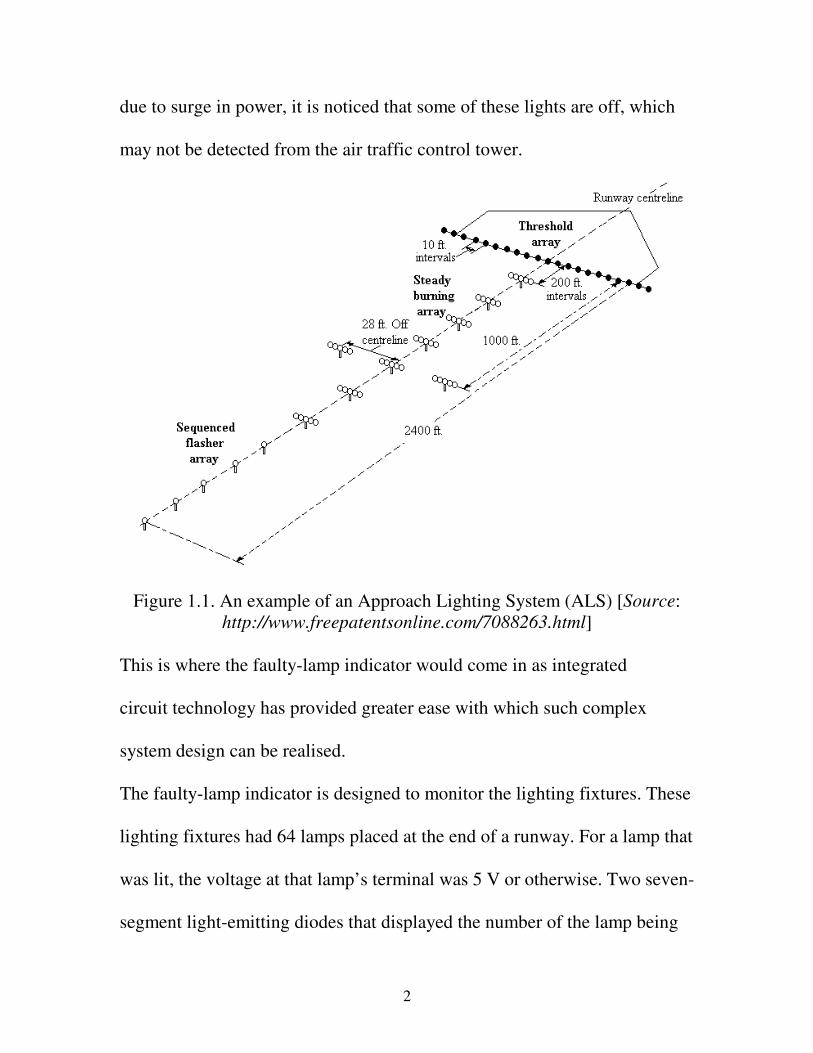
due to surge in power, it is noticed that some of these lights are off, which
may not be detected from the air traffic control tower.
Figure 1.1. An example of an Approach Lighting System (ALS) [Source:
http://www.freepatentsonline.com/7088263.html]
This is where the faulty-lamp indicator would come in as integrated
circuit technology has provided greater ease with which such complex
system design can be realised.
The faulty-lamp indicator is designed to monitor the lighting fixtures. These
lighting fixtures had 64 lamps placed at the end of a runway. For a lamp that
was lit, the voltage at that lamp’s terminal was 5 V or otherwise. Two seven-
segment light-emitting diodes that displayed the number of the lamp being

3
tested acted as the indicator output (0 to 63). If a lamp was faulty, an LED lit
up to show that number position. The timing was set for one minute for each
lamp that was being tested, using the 50 Hz, 220 V a.c. power line for each
64-minute cycle.
4
CHAPTER 2
2.1 SYSTEM REQUIREMENTS AND SOLUTION PLAN
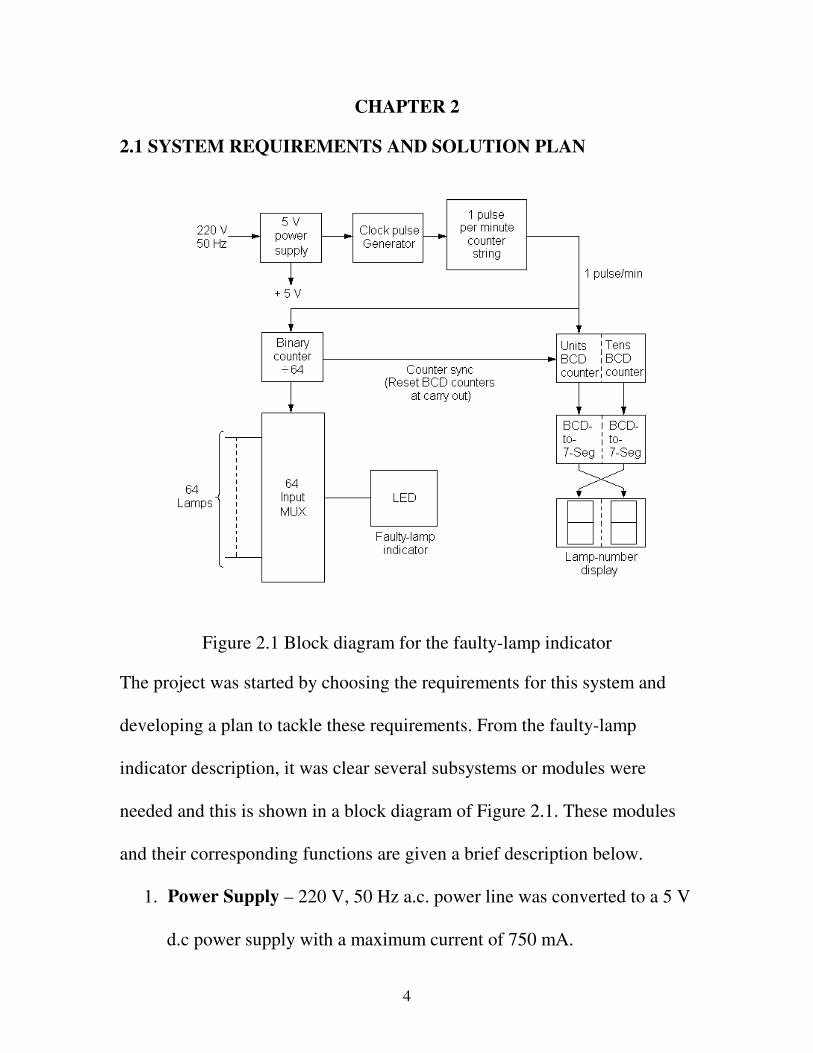
Figure 2.1 Block diagram for the faulty-lamp indicator
The project was started by choosing the requirements for this system and
developing a plan to tackle these requirements. From the faulty-lamp
indicator description, it was clear several subsystems or modules were
needed and this is shown in a block diagram of Figure 2.1. These modules
and their corresponding functions are given a brief description below.
1. Power Supply – 220 V, 50 Hz a.c. power line was converted to a 5 V
d.c power supply with a maximum current of 750 mA.

5
2. Clock Pulse Generator – This unit generated a 50 Hz clock pulse
from the a.c. power line to feed the counter string.
3. 1 Pulse per Minute Counter String – This counter string was used to
provide a pulse per minute using the 50 Hz clock pulse output and the
divide-by-3000 counter.
4. Divide-by-64 Binary Counter – This was used to generate the
addresses for the 64- and 4-input multiplexers.
5. Counter Sync – Here, the count of the BCD decade counter was
made to match with the count of the divide-by-64 counter.
6. BCD Decade Counter – The set of BCD decade counters was used to
count from 0 to 63.
7. Lamp-number Display – The decade counter drove a set of BCD-to-
seven-segment decoders and displayed the count on two digit seven-
segment displays.
8. 64-input Multiplexer – This unit had 64 lamp resistors fed in as
inputs to four 16-input multiplexers (addressed concurrently) and their
outputs were combined where they were addressed into a 4-input
multiplexer as inputs.
9. Lamp Indicator – The LOW output of the 4-input multiplexer caused
a light-emitting diode to energise and light up if one of the chosen

6
inputs (1 of 64) was LOW showing that the lamp of the runway being
checked was having a fault.
7
CHAPTER 3
3.1 SCHEMATIC DIAGRAM
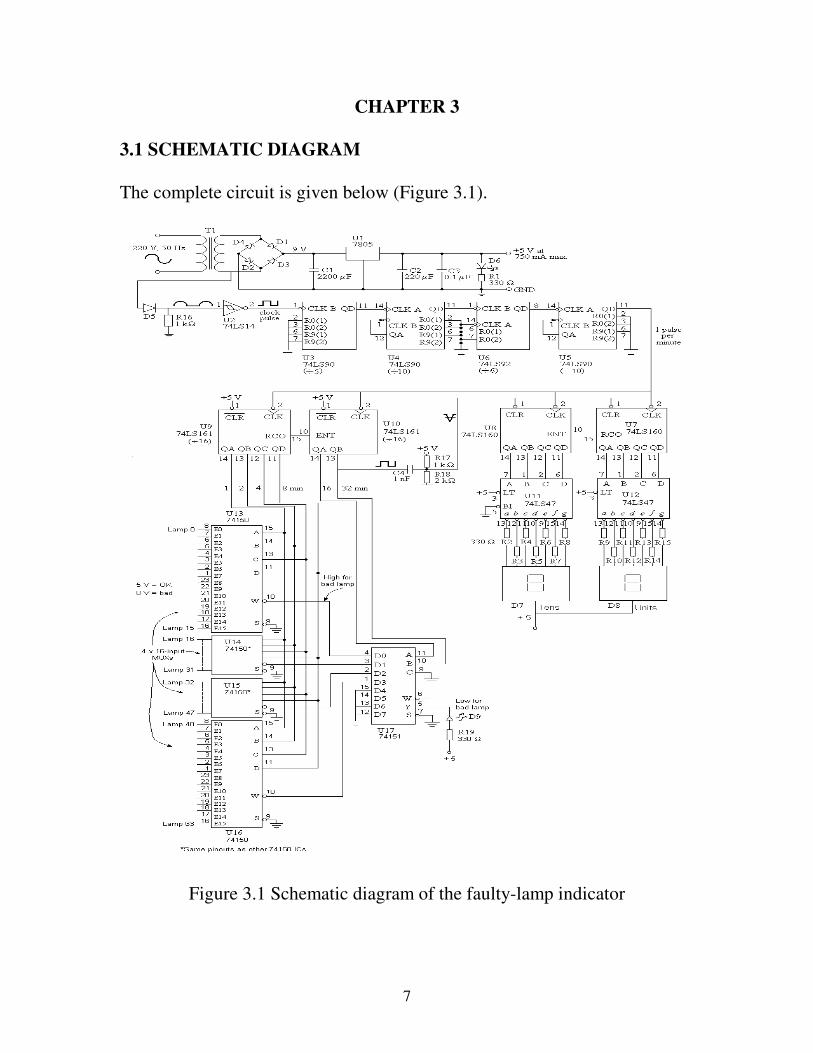
The complete circuit is given below (Figure 3.1).
Figure 3.1 Schematic diagram of the faulty-lamp indicator
8
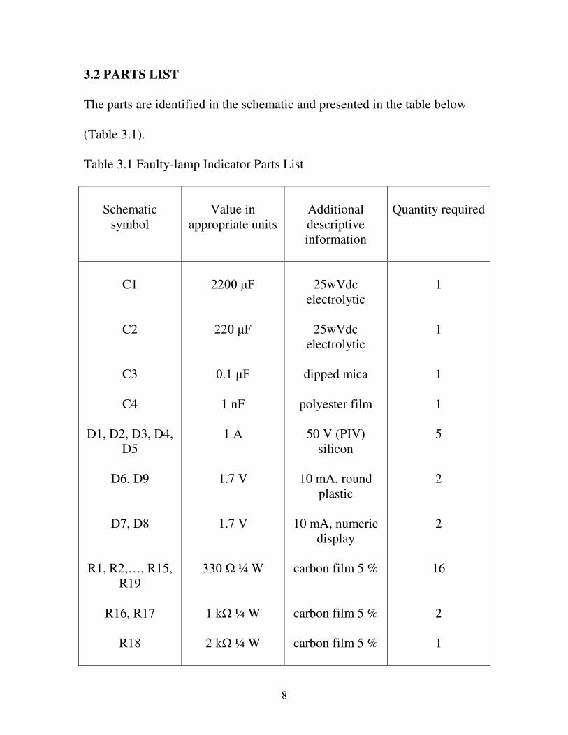
3.2 PARTS LIST
The parts are identified in the schematic and presented in the table below
(Table 3.1).
Table 3.1 Faulty-lamp Indicator Parts List
Schematic
symbol
Value in
appropriate units
Additional
descriptive
information
Quantity required
C1
C2
C3
C4
D1, D2, D3, D4,
D5
D6, D9
D7, D8
R1, R2,…, R15,
R19
R16, R17
R18
������)
�����)
�����)
1 nF
1 A
1.7 V
1.7 V
���� �¼ W
��N �¼ W
��N �¼ W
25wVdc
electrolytic
25wVdc
electrolytic
dipped mica
polyester film
50 V (PIV)
silicon
10 mA, round
plastic
10 mA, numeric
display
carbon film 5 %
carbon film 5 %
carbon film 5 %
1
1
1
1
5
2
2
16
2
1

9
T1
U1
U2
U3, U4, U6
U5
U7, U8
U9, U10
U11, U12
U13, U14, U15,
U16
U17
240-9 V
5 V
5 ± 0.25 V
5 ± 0.25 V
5 ± 0.25 V
5 ± 0.25 V
5 ± 0.25 V
5 ± 0.25 V
5 ± 0.25 V
5 ± 0.25 V
500 mA, iron-
core
TO-220 package
14-pin DIP
plastic
14-pin DIP
plastic
14-pin DIP
plastic
16-pin DIP
plastic
16-pin DIP
plastic
16-pin DIP
plastic
24-pin fat DIP
plastic
16-pin DIP
plastic
1
1
1
3
1
2
2
2
4
1

10
CHAPTER 4
4.1 CIRCUIT (LOGIC DESIGN) DESCRIPTION
4.1.1 POWER SUPPLY
A 5 V power supply was used to convert the 220 V, 50 Hz a.c. power line to
a 5 V d.c. regulated power, with a maximum current of 750 mA. This d.c.
power supply was obtained with T1 to provide the stepped down a.c.
voltage. D1, D2, D3 and D4 were then used to make a bridge rectifier for
producing the pulsating d.c. output, which was in turn fed into C1 combined
with the input resistance to U1. C2 was then used to improve the transient
response and kept the impedance low at high frequencies at the output. An
additional C3 with R1 and D6 were used in verifying that the connections
were correct, as the D6 lit up when T1 was connected to the mains and
switched on. The implementation of the regulated power supply is shown in
Figure 4.1.1.
Figure 4.1.1 Regulated Power Supply

11
4.1.2 CLOCK PULSE GENERATOR
This unit generated the 50 Hz clock pulse extracted from the a.c. power line,
which was used in feeding a counter string. The 50 Hz power line was used
as it has a very high accuracy of 0.1 % compared with the 555 timer, which
has just an accuracy of 1.0 % and the 555 astable is best suited to holding a
particular frequency rather than operating at a certain frequency. The power
company in maintaining the grid ensures that the 50 Hz power line
frequency is very precise. This frequency is speeded up or slowed down as
needed during peak periods and in a given day is 4,320,000 cycles (= 50 Hz
x 86 400 s). Therefore, it is very accurate over a long period when used in
digital application. The signal input from the a.c. power line through T1 was
half-wave rectified using D5 and R16 used to reference the clock signal to
the ground. It was then processed through U2 to produce a clean 0 to 5 V
pulse train so that it was compatible with the digital TTL circuitry.
The logic design is as shown in Figure 4.1.2.
Figure 4.1.2 Clock pulse generator

12
4.1.3 ONE PULSE PER MINUTE COUNTER STRING
The counter string was used to provide a pulse per minute using the 50 Hz
clock pulse output and a divide-by-3000 counter. There was a sequence of
counters, which was fed with the 50 Hz clock pulse that was obtained from
the pulse generator. U4 was used to get tens of seconds (or minutes) from a
one second (or one minute) count pulse while U3 was used to generate the
sequence of one-minute pulse from ‘tens of seconds’ signal. Since the pulses
from the power line via the pulse generator were being produced at a rate of
50 per second, the start/ signal was used to apply (or inhibit) the count
pulses. A modulo-3000 counter was therefore used. The first modulo-50
counter was used to reduce the pulse frequency to one per second and this
was implemented by cascading U3 with U4. The second additional modulo-
60 counter using U6 and U5, was used to produce the one pulse per minute.
The logic design of the divide-by-3000 for a pulse per minute counter
string is shown in Figure 4.1.3.
Figure 4.1.3 One pulse per minute Counter String

13
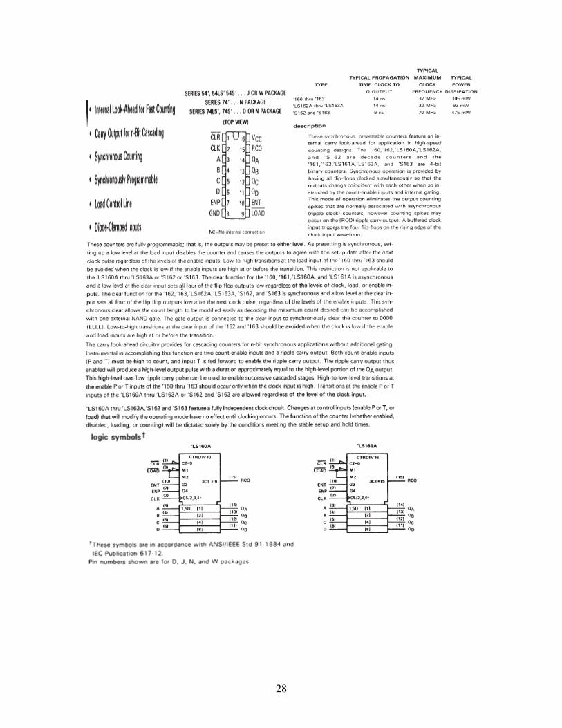
4.1.4 DIVIDE-BY-64 BINARY COUNTER
This was used to generate the addresses for 64- and 4-input multiplexers,
counting 0 to 63 in binary. As 4-bit counters can count from 0 to 15, the
module was made a long count with the use of U9 and U10 cascaded
together. The divide-by-64 counter was synchronously loaded with value 0
after it had reached a count of 63. This meant for it to RESET back to 0 after
counting to 63, the reset was made active-low, that is set HIGH (+VCC) for
normal operation so as to produce a low output at the desired count. This is
because the RESET function ( ) must normally occur immediately and
should reset on the next count above the maximum that is required. The
clock inputs were linked from the pulse per minute counter string and the
carry-out of the lower-bit counter, U9 was used to feed the carry-in of the
next higher-bit counter, U10. This was to ensure that the entire counter chain
was synchronous with every output changing at the same time. The outputs
that were generated were addressed as inputs to the 64-input multiplexer and
lamp indicator module.
The logic design is shown in Figure 4.1.4.

14
Figure 4.1.4 Divide-by-64 counter
4.1.5 COUNTER SYNC
Here, the count of the BCD decade counter was made to match with the
count of the divide-by-64 counter. The divide-by-64 counter was set to send
a signal to the BCD decade counter to recognise when it had reached 64th
count after which the BCD decade counter starts from count 0. To make sure
there were no interfacing problems between both counters, the counter sync
module was to provide for a narrow input pulse in response to the above
event. This could be done in several ways and they included using the
monostable, the comparator, or the RC differentiator. To keep the project
simple and manageable, the RC differentiator was utilised.
As the RC differentiator is useful for detecting leading and trailing edges in
pulse signals, trigger pulses were to be generated at either the leading or
trailing edges of the pulse train. This required that the differentiating circuit
provided a narrow output pulse for every input-level transition by
15
differentiating the inputs, that is, it would generate spikes at the transitions
of the input signal. It should be noted that the positive output spike of
amplitude 5 V followed each positive input transition and vice versa. It
would therefore act as a square-to-pulse converter. Since the counters were
working with discrete time signals, timing was of great significance and
transitions were to occur at carefully controlled points in time. The BCD
decade counter needed a generated trigger pulse to control the timing for
reset.
As the differentiator was to have a very short time constant, its effectiveness
relied very much upon the ratio of time constant, 2�( = RC ) to periodic time,
t ( = f –1
) as 2 << t.
In order to get this, the time constant was made small, taking care not to load
the input by making R too small (at the transition, the voltage change across
the capacitor was zero as it blocked the constant d.c. voltage in the BCD
decade counter from reaching the divide-by-64 counter so that R was the
load as seen by the input). To get the values that was to be used by the BCD
decade counter circuit, the condition 2 < 0.0001t was used. For C4, value of
1 nF was used (any value between 1 to 10nF was adequate) and since the
frequency is 50 Hz, R18 value was calculated using the equation 2 = 0.001t.
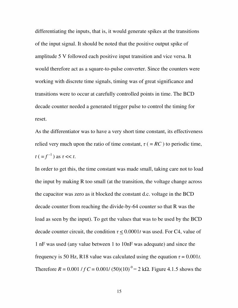
Therefore R = 0.001 / f C = 0.001/ (50)(10)-9 ���N ��)LJXUH�������VKRZV�WKH�
16
RC circuit’s output with the input.
Figure 4.1.5 RC differentiator
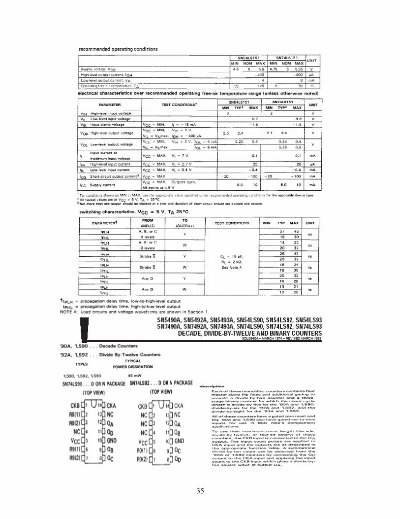
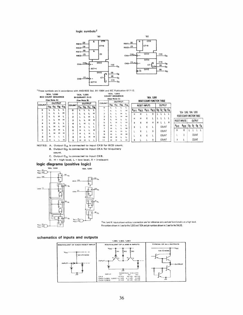
4.1.6 BCD DECADE COUNTER
This module was to count the number of pulses that entered via the input
circuit and output this number to the decoder circuitry. The counter was
started, stopped and reset by the clock so provision was made for a start,
stop and reset input. The BCD (binary-coded decimal) decade counter was
made to behave like a binary counter until state 63 was reached. At this
point, the control circuitry was to prepare the next flip-flop inputs so that the
next clock pulse would force the counter back to state 0 instead of allowing
the next binary count, state 64 to be reached. This resetting was done with
the use of the trigger pulse fed from the RC differentiator, which ensured
that the count was well matched with that of the divide-by-64 counter.
Because the counting ranged from 0 to 63, U7 and U8 were cascaded
together by connecting the ripple carry-out pin of the lower-bit of U7 to the
enable T (or carry-in) pin of the higher-bit counter, U8. Figure 4.1.6 shows

17
the module design.
Figure 4.1.6 BCD decade counter
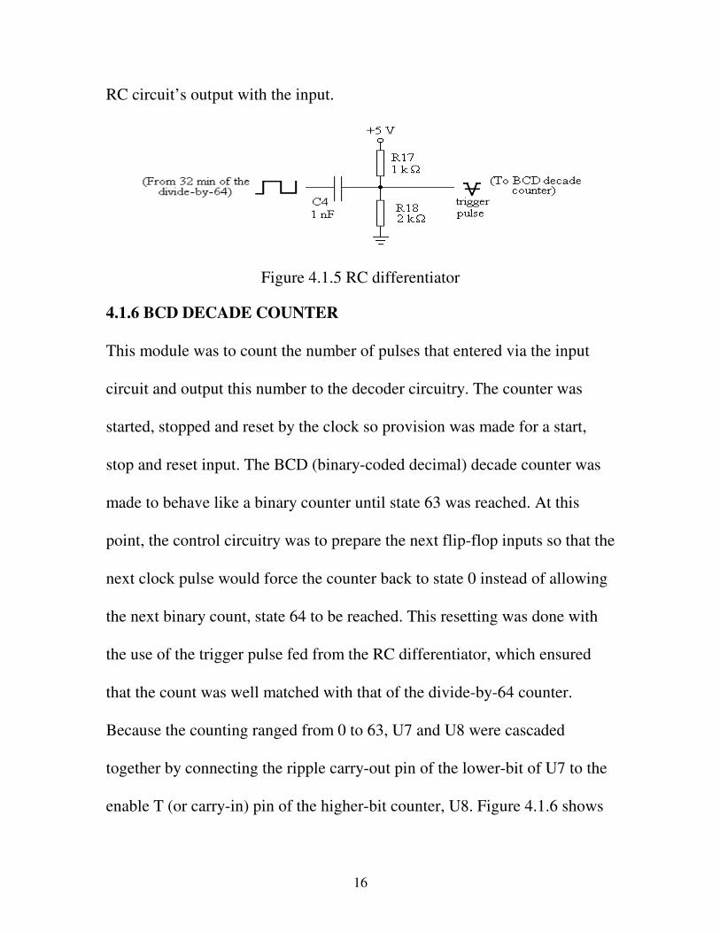
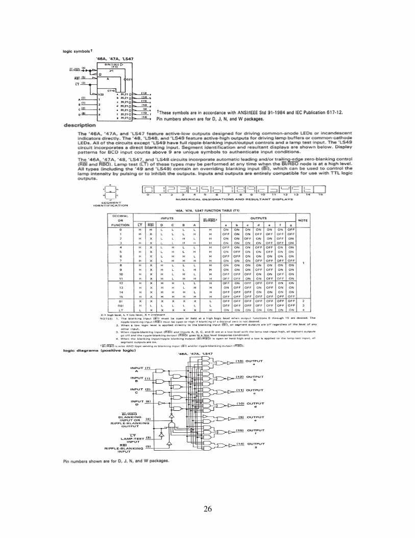
4.1.7 LAMP-NUMBER DISPLAY
As the output of the BCD decade counter was in binary, a decoding
application was required, which allowed for reading on the lamp-number
display. The outputs of the BCD decade counter were fed into U11 and U12.
U11 and U12 were used with D7 and D8 as the decoder circuit was made
to work with a series of voltages and currents. For D7 and D8, R2, R3,…,
R15 were required between U11’s and U12’s open collector outputs and the
display inputs to the VCC = +5 V source through each segment of the LED
drivers as inputs (Figure 4.1.7). The blanking input of the U11 was set on
active-high (that is, it was grounded). This caused the binary value 0 not to
be displayed while the lamp test of the decoder was set on active-low during
operation.
18
Figure 4.1.7 Lamp-number display
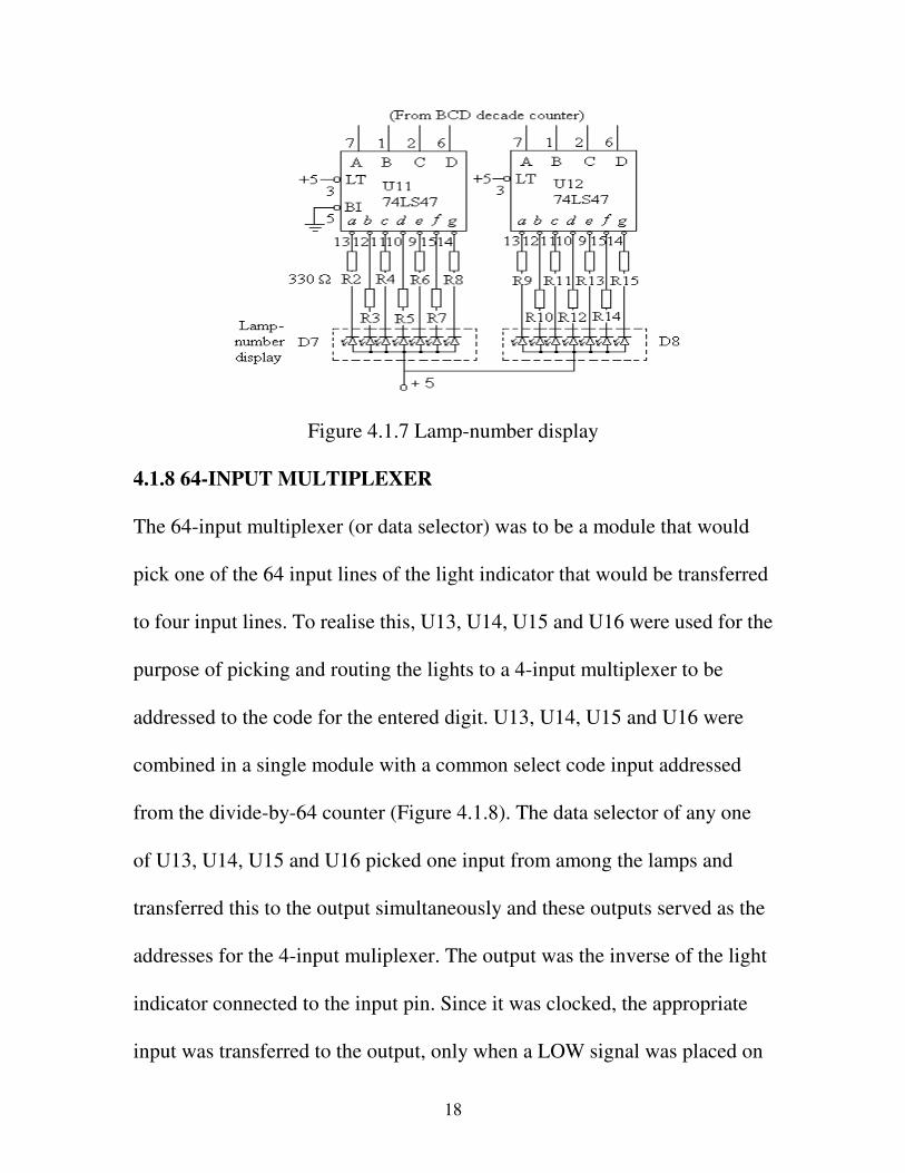
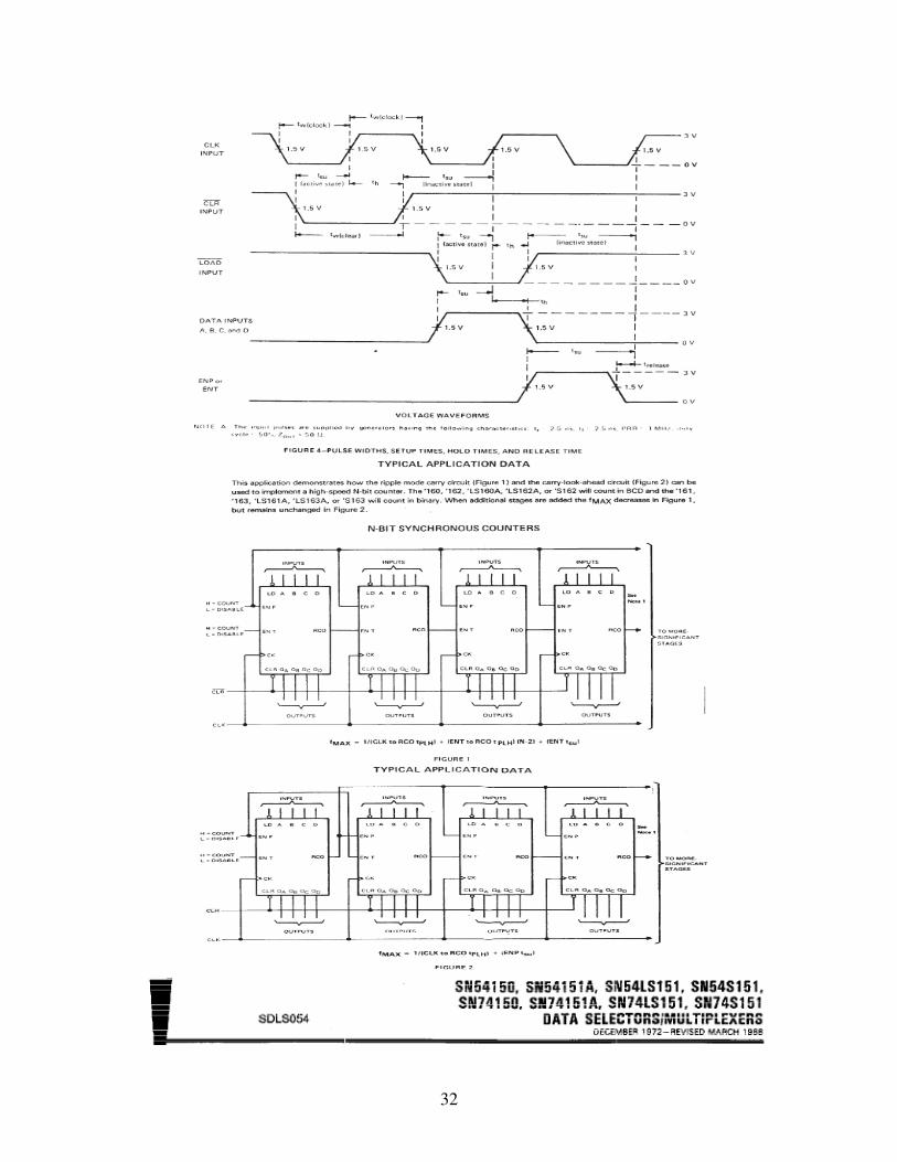
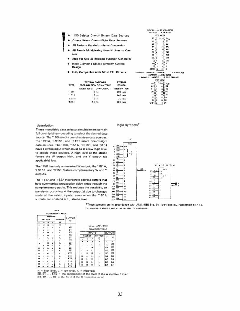
4.1.8 64-INPUT MULTIPLEXER
The 64-input multiplexer (or data selector) was to be a module that would
pick one of the 64 input lines of the light indicator that would be transferred
to four input lines. To realise this, U13, U14, U15 and U16 were used for the
purpose of picking and routing the lights to a 4-input multiplexer to be
addressed to the code for the entered digit. U13, U14, U15 and U16 were
combined in a single module with a common select code input addressed
from the divide-by-64 counter (Figure 4.1.8). The data selector of any one
of U13, U14, U15 and U16 picked one input from among the lamps and
transferred this to the output simultaneously and these outputs served as the
addresses for the 4-input muliplexer. The output was the inverse of the light
indicator connected to the input pin. Since it was clocked, the appropriate
input was transferred to the output, only when a LOW signal was placed on
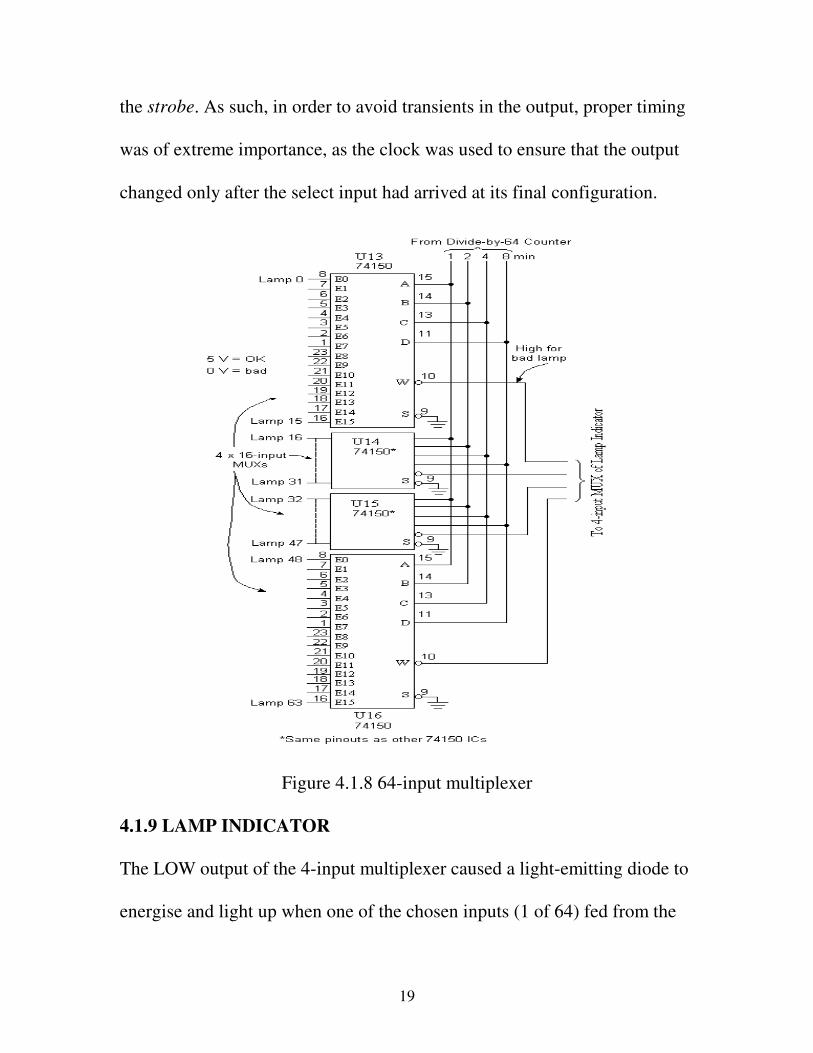
19
the strobe. As such, in order to avoid transients in the output, proper timing
was of extreme importance, as the clock was used to ensure that the output
changed only after the select input had arrived at its final configuration.
Figure 4.1.8 64-input multiplexer
4.1.9 LAMP INDICATOR
The LOW output of the 4-input multiplexer caused a light-emitting diode to
energise and light up when one of the chosen inputs (1 of 64) fed from the
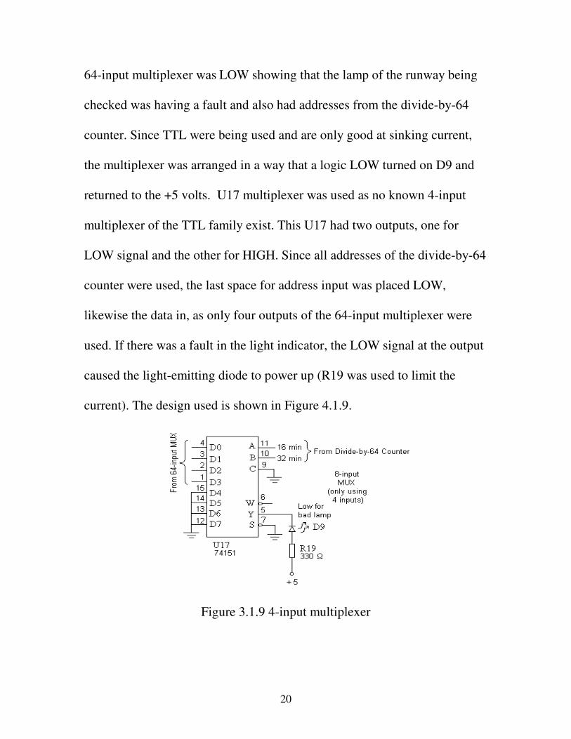
20
64-input multiplexer was LOW showing that the lamp of the runway being
checked was having a fault and also had addresses from the divide-by-64
counter. Since TTL were being used and are only good at sinking current,
the multiplexer was arranged in a way that a logic LOW turned on D9 and
returned to the +5 volts. U17 multiplexer was used as no known 4-input
multiplexer of the TTL family exist. This U17 had two outputs, one for
LOW signal and the other for HIGH. Since all addresses of the divide-by-64
counter were used, the last space for address input was placed LOW,
likewise the data in, as only four outputs of the 64-input multiplexer were
used. If there was a fault in the light indicator, the LOW signal at the output
caused the light-emitting diode to power up (R19 was used to limit the
current). The design used is shown in Figure 4.1.9.
Figure 3.1.9 4-input multiplexer

21
CHAPTER 5
CONCLUSION AND RECOMMENDATION
5.1 CONCLUSION
The realisation of the faulty-lamp indicator shows that this working
prototype can be effectively utilised in airports, as the workers, who usually
rely on sight at the control tower unit, are responsible for movements around
an airport. As it is continuously operative, undesirable downtime of the
lighting system is avoided.
5.2 RECOMMENDATION
The design of the faulty-lamp indicator can be improved upon by
incorporating a piezo transducer on a fault monitor with the runway lighting
system. The piezo transducer, which is an output transducer, would convert
directly the output of the electrical signal of the faulty-lamp indicator to
sound. As it requires a small current, usually less than 10mA, it would be
ideal for buzzes and beeps.
22
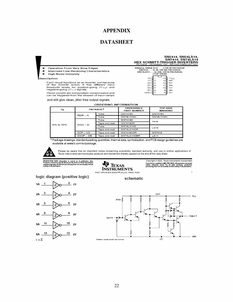
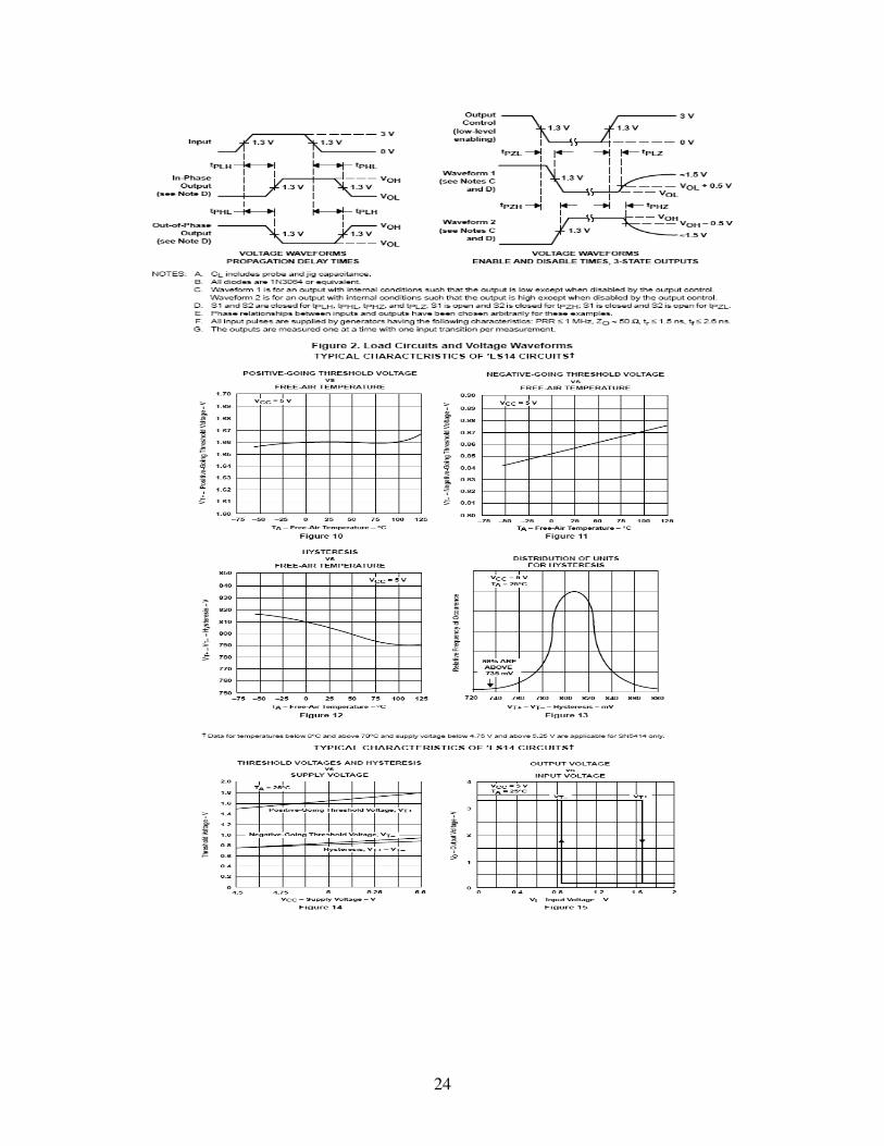
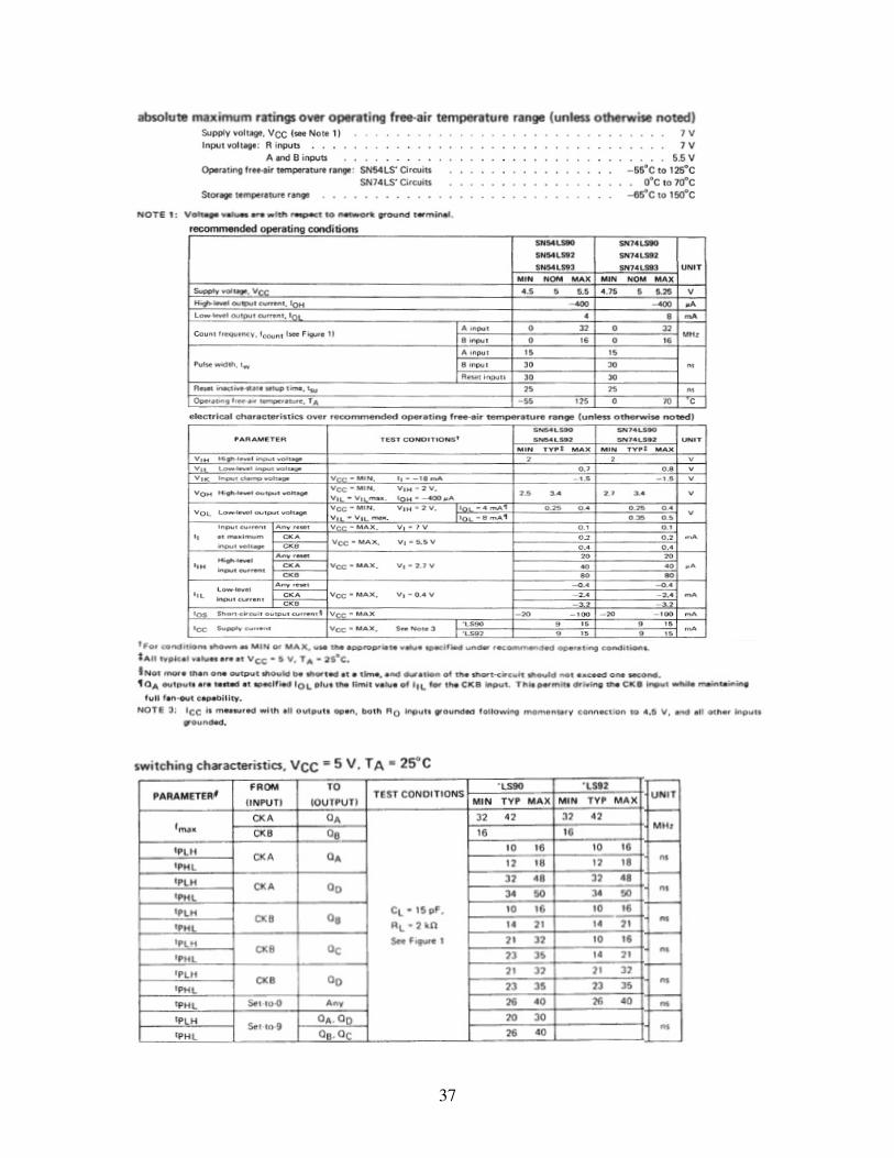
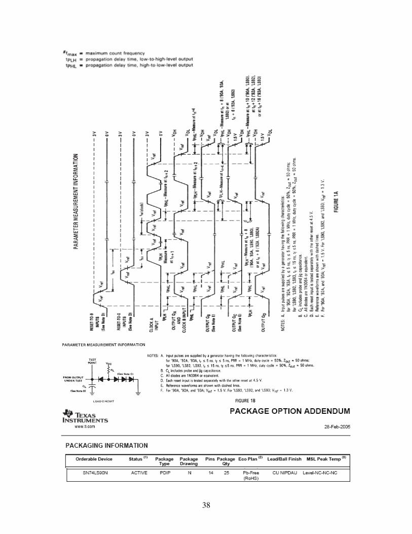
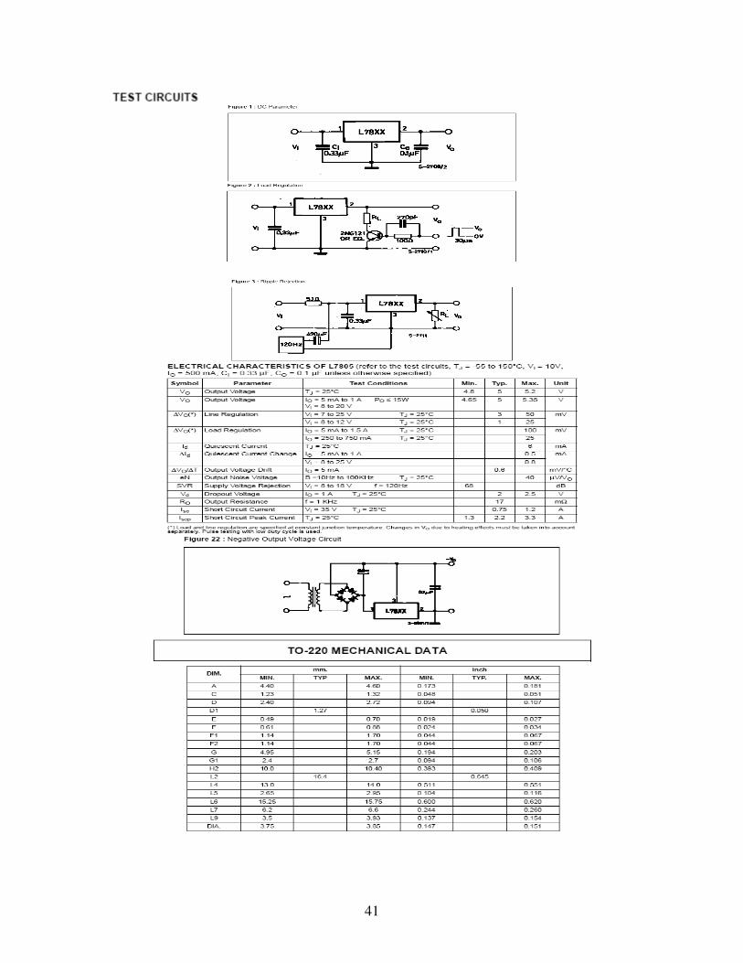
APPENDIX
DATASHEET

23
24

25
26

27
28

29
30
31
32
33

34
35
36
37
38

39

40
41

42

43

44
REFERENCES
1. Ashford, N. and Wright, P. (1979) Airport Engineering, John Wiley
and Sons, Inc., New Jersey, 130-140.
2. Bignell, J. and Donovan, R. (1994) Digital Electronics, 3rd
Edition,
Delmar Publishers, Inc., New York, 42, 232, 369, 372, 387, 462-
463, 468-471, 544-546.
3. Esser, D. (2007) Airport Lights and Markings,
www.erau.edu/er/newsmedia/articles/cont12.html, (Embry-
Riddle).
4. Fowler, R. J. (1999) Electricity: Principles and Applications, 5th
Edition, Glencoe McGraw-Hill Columbus, Ohio, 67-68.
5. Horowitz, P. and Hill, W. (1989) The Art of Electronics, 2nd
Edition,
Cambridge University Press, Cambridge, 26, 57.
6. Hopkinson, R. G. (1983) Lighting and Lighting Devices. In:
Encyclopaedia Britannica, Macropedia, Vol. 10, 15th
Edition, Preece,
W. E. (Editor), Encyclopaedia Britannica Inc., Chicago, 962.
7. Nelson, P. V. et al. (1995) Digital Logic Circuit Analysis and Design,
Prentice-Hall, Inc., New Jersey, 258-259, 270, 272-274, 464-467,
471-475.
8. Olatinsu, O. B. (1996) Traffic Control Signals for Cross Roads. B. Sc

45
physics project, Physics Department, Science Faculty, University of
Lagos.
9. Savant, C. J. et al. (1991) Electronic Design: Circuits and System, 2nd
Edition, The Benjamin/Cummings Publishing Company, Inc.,
California, 59-61, 271-273, 627-628, 657-658, 668, 728-730, 733-
735, 748-750, 754, 799-803.
10. Sinclair, I. And Lewis, G. (2002) Electronic and Electrical Servicing:
Level 2, 4th
Edition, Newnes Publications, Oxford, 122, 139.
11. Tooley, M. (1995) Electronic Circuits: Fundamentals and
Application, Newnes Publications, Oxford, 57-58, 75-77, 84, 88-90,
101, 105, 114, 173.
12. Datasheet catalog for integrated circuits, diodes, triacs and other
semiconductors (2006) www.datasheetcatalog.com,
(DatasheetCatalog).