Embed Size (px)
Citation preview
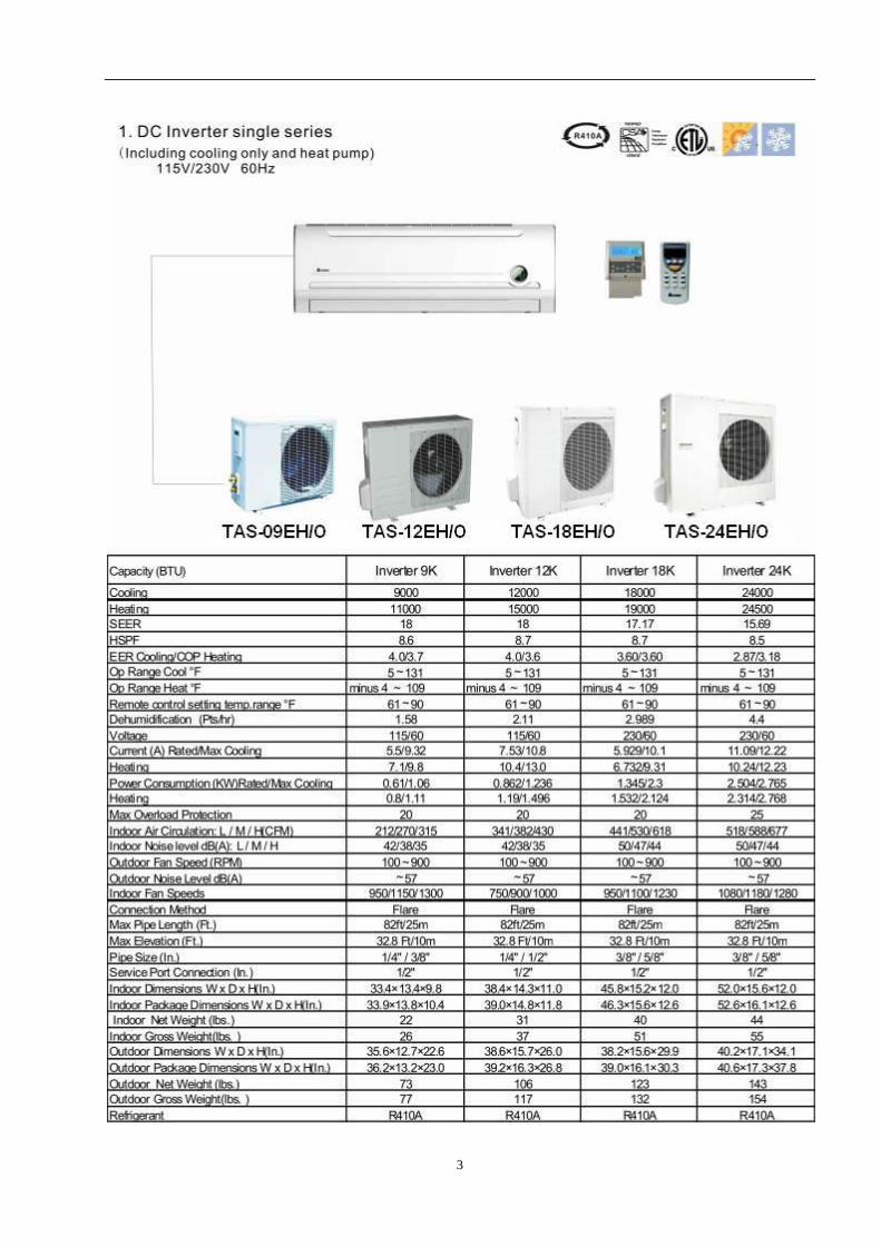
DC Inverter Split Air-Condition Unit
SERVICE MANUAL
2
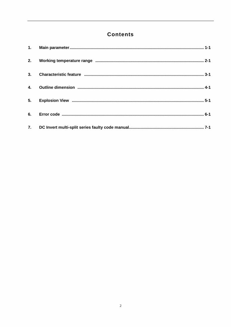
Contents
1. Main parameter........................................................................................................................ 1-1
2. Working temperature range ................................................................................................. 2-1
3. Characteristic feature ........................................................................................................... 3-1
4. Outline dimension ................................................................................................................. 4-1
5. Explosion View ...................................................................................................................... 5-1
6. Error code ............................................................................................................................... 6-1
7. DC Invert multi-split series faulty code manual................................................................... 7-1
3
4
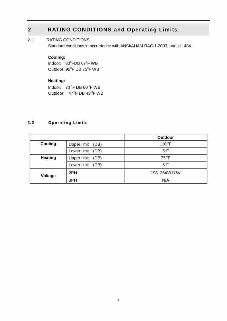
2 RATING CONDITIONS and Operating Limits
2.1 RATING CONDITIONS Standard conditions in accordance with ANSI/AHAM RAC-1-2003, and UL 484.
Cooling: Indoor: 80oFDB 67oF WB Outdoor: 95oF DB 75oF WB
Heating: Indoor: 70 oF DB 60 oF WB Outdoor: 47 oF DB 43 oF WB
2.2 Operat ing L imits
Outdoor Upper limit (DB) 110 oF Cooling Lower limit (DB) 5oF Upper limit (DB) 75 oF Heating Lower limit (DB) 5oF
2PH 198–264V/115V Voltage
3PH N/A
5
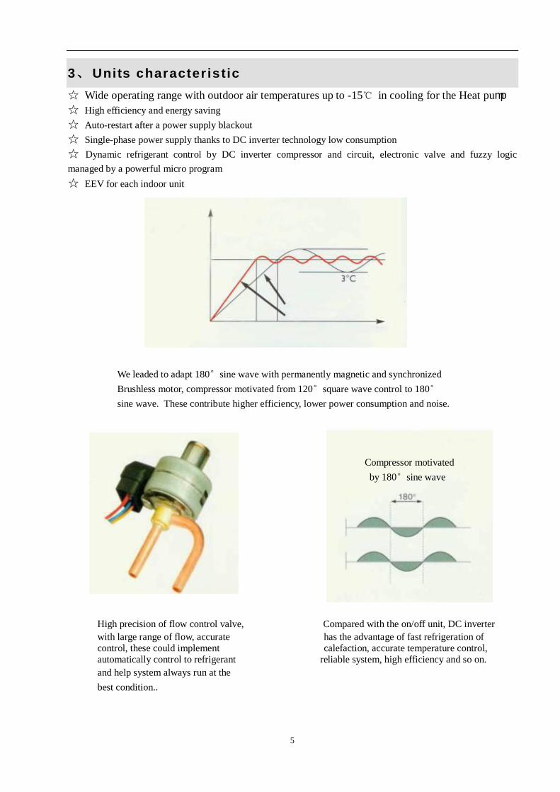
3、 Units character istic ☆ Wide operating range with outdoor air temperatures up to -15℃ in cooling for the Heat pump ☆ High efficiency and energy saving ☆ Auto-restart after a power supply blackout ☆ Single-phase power supply thanks to DC inverter technology low consumption ☆ Dynamic refrigerant control by DC inverter compressor and circuit, electronic valve and fuzzy logic managed by a powerful micro program ☆ EEV for each indoor unit
We leaded to adapt 180°sine wave with permanently magnetic and synchronized Brushless motor, compressor motivated from 120°square wave control to 180° sine wave. These contribute higher efficiency, lower power consumption and noise.
Compressor motivated by 180°sine wave
High precision of flow control valve, Compared with the on/off unit, DC inverter with large range of flow, accurate has the advantage of fast refrigeration of control, these could implement calefaction, accurate temperature control, automatically control to refrigerant reliable system, high efficiency and so on. and help system always run at the best condition..
6
7
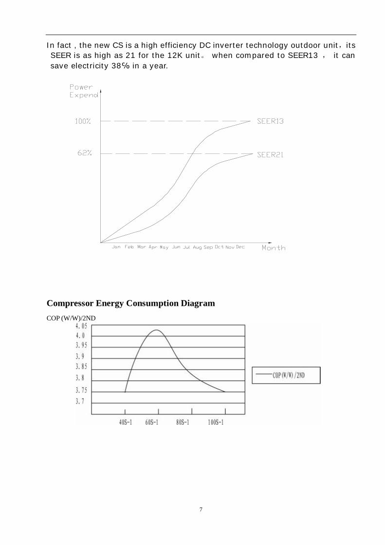
In fact , the new CS is a high efficiency DC inverter technology outdoor unit,its SEER is as high as 21 for the 12K unit。 when compared to SEER13 , it can save electricity 38℅ in a year.
Compressor Energy Consumption Diagram COP (W/W)/2ND
8
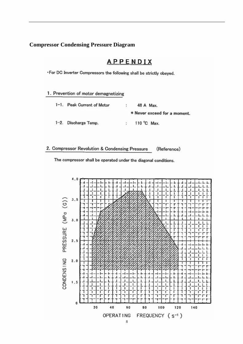
Compressor Condensing Pressure Diagram
9
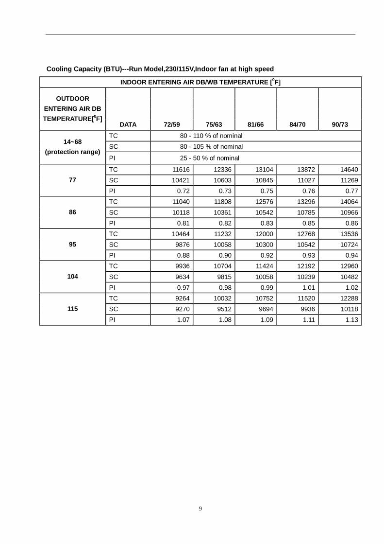
Cooling Capacity (BTU)---Run Model,230/115V,Indoor fan at high speed
INDOOR ENTERING AIR DB/WB TEMPERATURE [0F]
OUTDOOR ENTERING AIR DB TEMPERATURE[0F]
DATA 72/59 75/63 81/66 84/70 90/73 TC 80 - 110 % of nominal
SC 80 - 105 % of nominal 14~68
(protection range) PI 25 - 50 % of nominal
TC 11616 12336 13104 13872 14640 SC 10421 10603 10845 11027 11269 77 PI 0.72 0.73 0.75 0.76 0.77 TC 11040 11808 12576 13296 14064
SC 10118 10361 10542 10785 10966 86 PI 0.81 0.82 0.83 0.85 0.86 TC 10464 11232 12000 12768 13536 SC 9876 10058 10300 10542 10724 95 PI 0.88 0.90 0.92 0.93 0.94 TC 9936 10704 11424 12192 12960
SC 9634 9815 10058 10239 10482 104 PI 0.97 0.98 0.99 1.01 1.02 TC 9264 10032 10752 11520 12288 SC 9270 9512 9694 9936 10118 115 PI 1.07 1.08 1.09 1.11 1.13
10
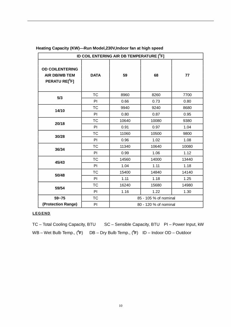
Heating Capacity (KW)---Run Model,230V,Indoor fan at high speed
ID COIL ENTERING AIR DB TEMPERATURE [0F]
OD COILENTERING AIR DB/WB TEM PERATU RE[0F]
DATA 59 68 77
TC 8960 8260 7700 5/3
PI 0.66 0.73 0.80 TC 9940 9240 8680
14/10 PI 0.80 0.87 0.95 TC 10640 10080 9380
20/18 PI 0.91 0.97 1.04 TC 11060 10500 9800
30/28 PI 0.96 1.02 1.08 TC 11340 10640 10080
36/34 PI 0.99 1.06 1.12 TC 14560 14000 13440
45/43 PI 1.04 1.11 1.18 TC 15400 14840 14140
50/48 PI 1.11 1.18 1.25 TC 16240 15680 14980
59/54 PI 1.16 1.22 1.30 TC 85 - 105 % of nominal 59~75
(Protection Range) PI 80 - 120 % of nominal
L E G E N D
TC – Total Cooling Capacity, BTU SC – Sensible Capacity, BTU PI – Power Input, kW
WB – Wet Bulb Temp., (0F) DB – Dry Bulb Temp., (0F) ID – Indoor OD – Outdoor
11
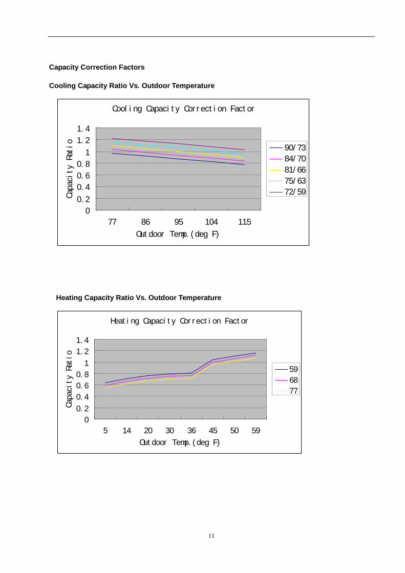
Capacity Correction Factors
Cooling Capacity Ratio Vs. Outdoor Temperature
Heating Capacity Ratio Vs. Outdoor Temperature
Cooling Capacity Correction Factor
0
0.2
0.4
0.6
0.8
1
1.2
1.4
77 86 95 104 115
Outdoor Temp.(deg F)
Capacity Ratio
90/73
84/70
81/66
75/63
72/59
Heating Capacity Correction Factor
0
0.2
0.4
0.6
0.8
1
1.2
1.4
5 14 20 30 36 45 50 59
Outdoor Temp.(deg F)
Capacity Ratio
59
68
77
12
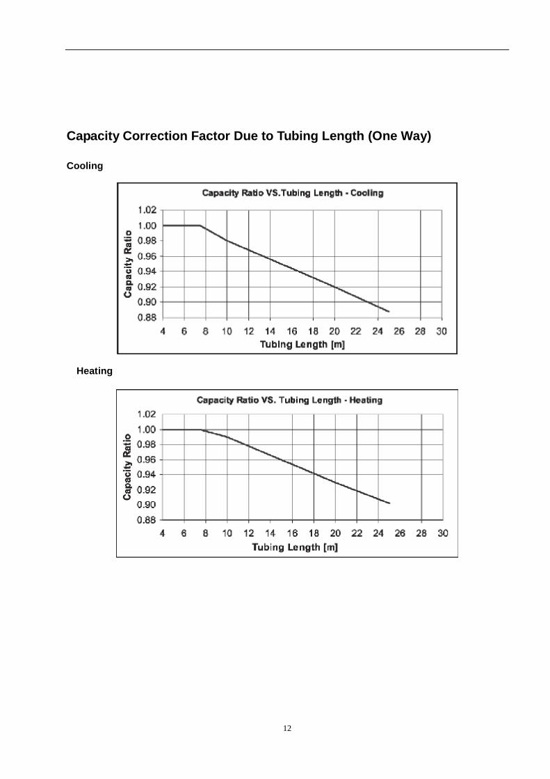
Capacity Correction Factor Due to Tubing Length (One Way)
Cooling
Heating
13
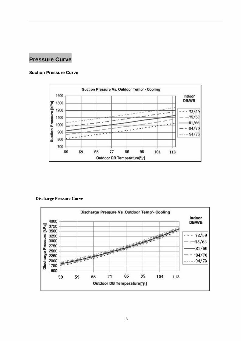
Pressure Curve
Suction Pressure Curve
Discharge Pressure Curve
14
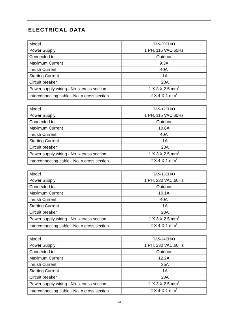
ELECTRICAL DATA
Model TAS-09EH/O Power Supply 1 PH, 115 VAC,60Hz Connected to Outdoor Maximum Current 9.3A Inrush Current 40A Starting Current 1A Circuit breaker 20A Power supply wiring - No. x cross section 1 X 3 X 2.5 mm2 Interconnecting cable - No. x cross section 2 X 4 X 1 mm2
Model TAS-12EH/O Power Supply 1 PH, 115 VAC,60Hz Connected to Outdoor Maximum Current 10.8A Inrush Current 40A Starting Current 1A Circuit breaker 20A Power supply wiring - No. x cross section 1 X 3 X 2.5 mm2 Interconnecting cable - No. x cross section 2 X 4 X 1 mm2
Model TAS-18EH/O Power Supply 1 PH, 230 VAC,60Hz Connected to Outdoor Maximum Current 10.1A Inrush Current 40A Starting Current 1A Circuit breaker 20A Power supply wiring - No. x cross section 1 X 3 X 2.5 mm2 Interconnecting cable - No. x cross section 2 X 4 X 1 mm2
Model TAS-24EH/O Power Supply 1 PH, 230 VAC,60Hz Connected to Outdoor Maximum Current 12.2A Inrush Current 35A Starting Current 1A Circuit breaker 20A Power supply wiring - No. x cross section 1 X 3 X 2.5 mm2
Interconnecting cable - No. x cross section 2 X 4 X 1 mm2
15
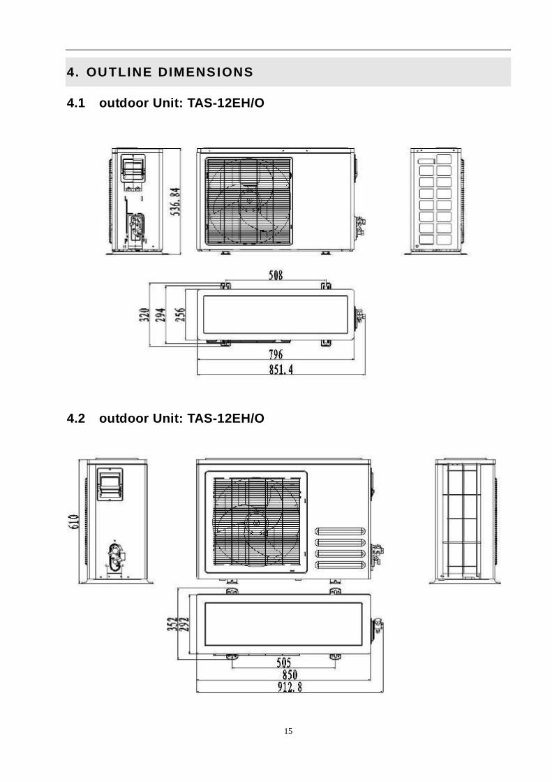
4. OUTLINE DIMENSIONS
4.1 outdoor Unit: TAS-12EH/O
4.2 outdoor Unit: TAS-12EH/O
16
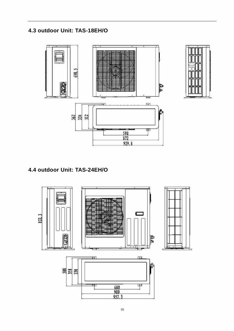
4.3 outdoor Unit: TAS-18EH/O
4.4 outdoor Unit: TAS-24EH/O
17
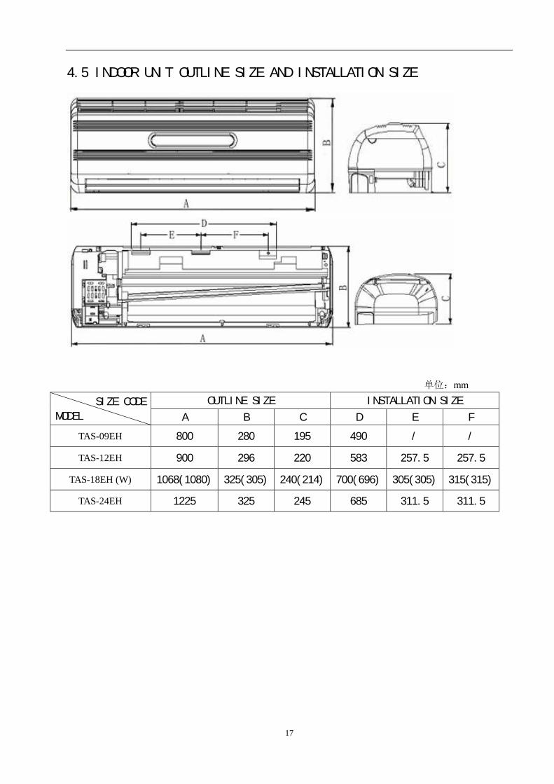
4.5 INDOOR UNIT OUTLINE SIZE AND INSTALLATION SIZE
单位:mm
OUTLINE SIZE INSTALLATION SIZE SIZE CODE
MODEL A B C D E F
TAS-09EH 800 280 195 490 / /
TAS-12EH 900 296 220 583 257.5 257.5
TAS-18EH (W) 1068(1080) 325(305) 240(214) 700(696) 305(305) 315(315)
TAS-24EH 1225 325 245 685 311.5 311.5
18
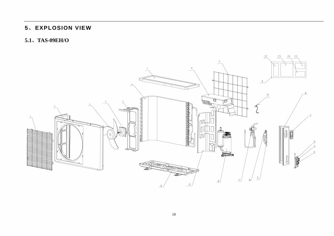
5、 EXPLOSION VIEW
5.1、TAS-09EH/O
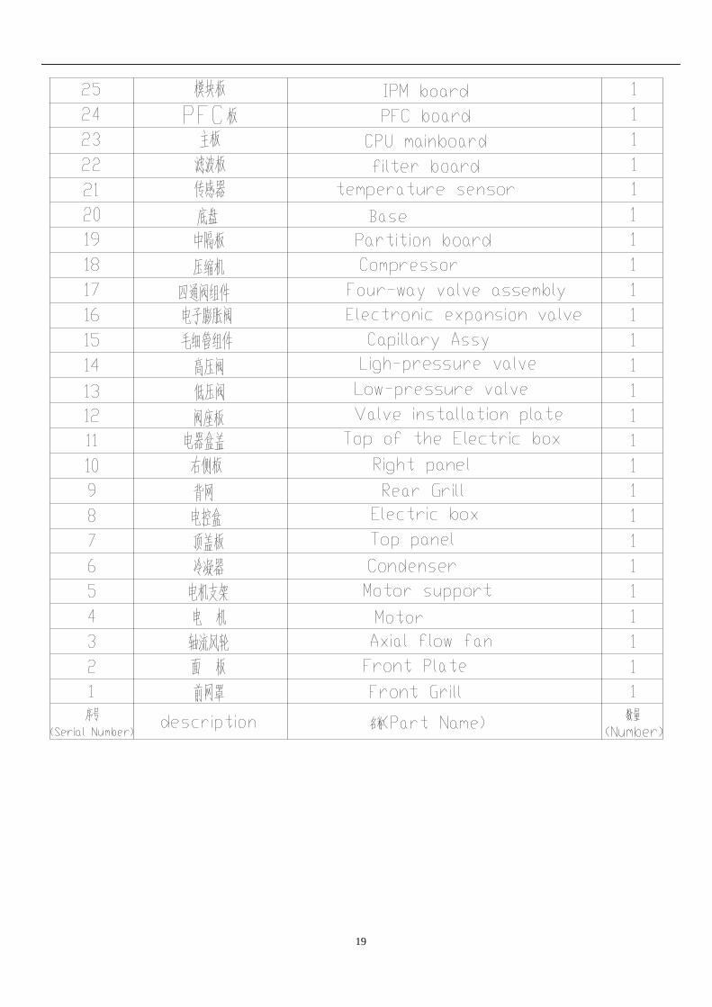
19
20
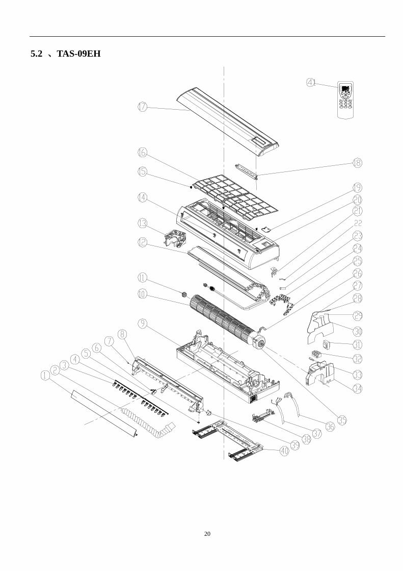
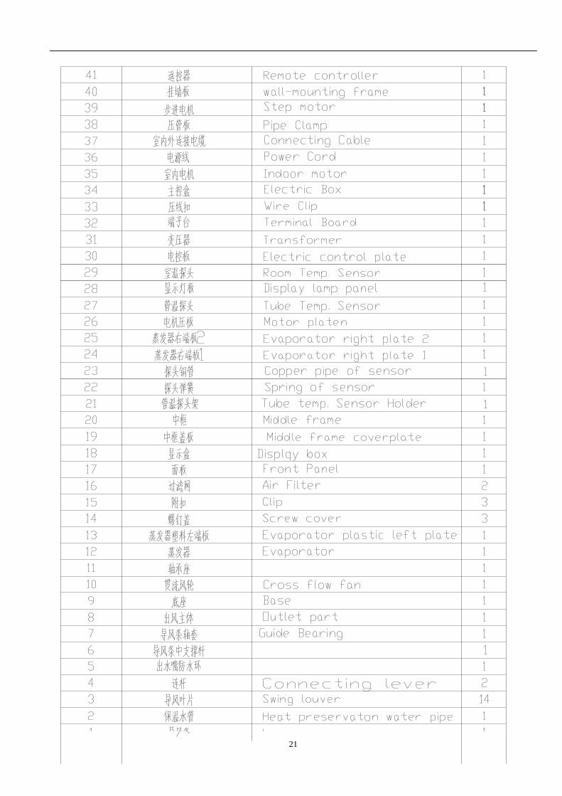
5.2 、TAS-09EH
ONO FF
21
22
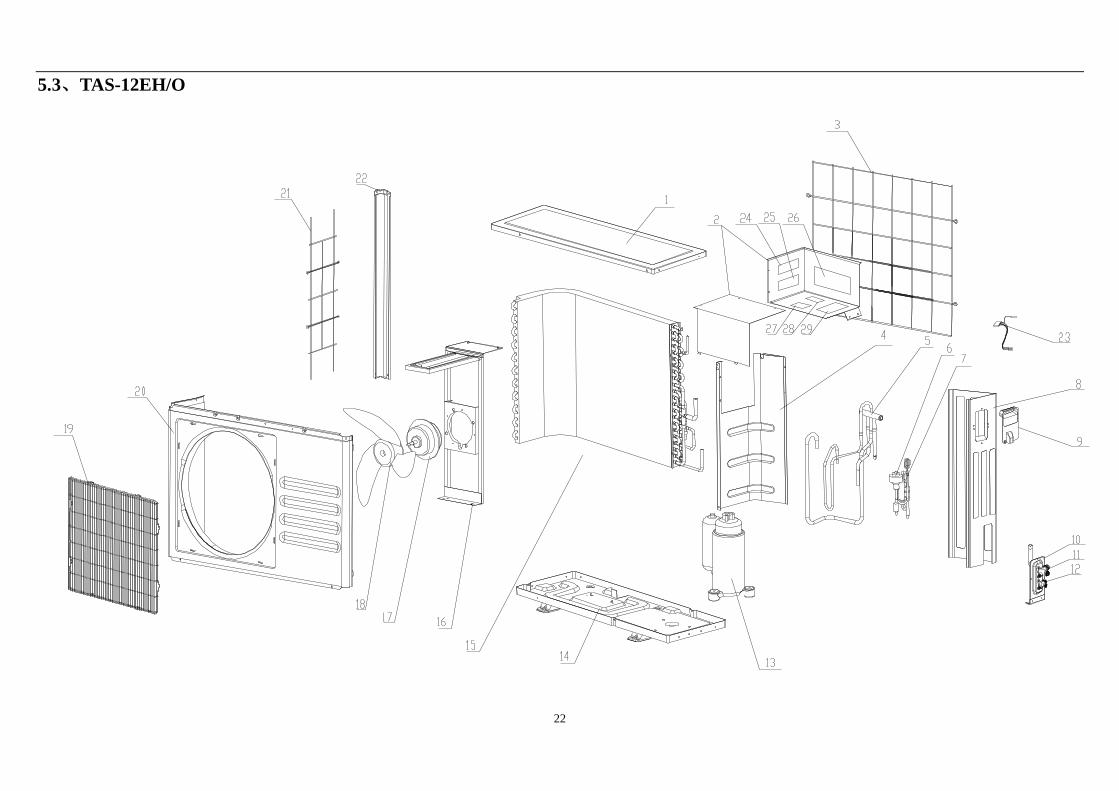
5.3、TAS-12EH/O
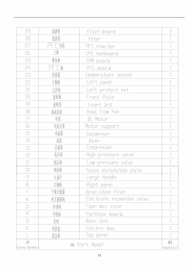
23
24
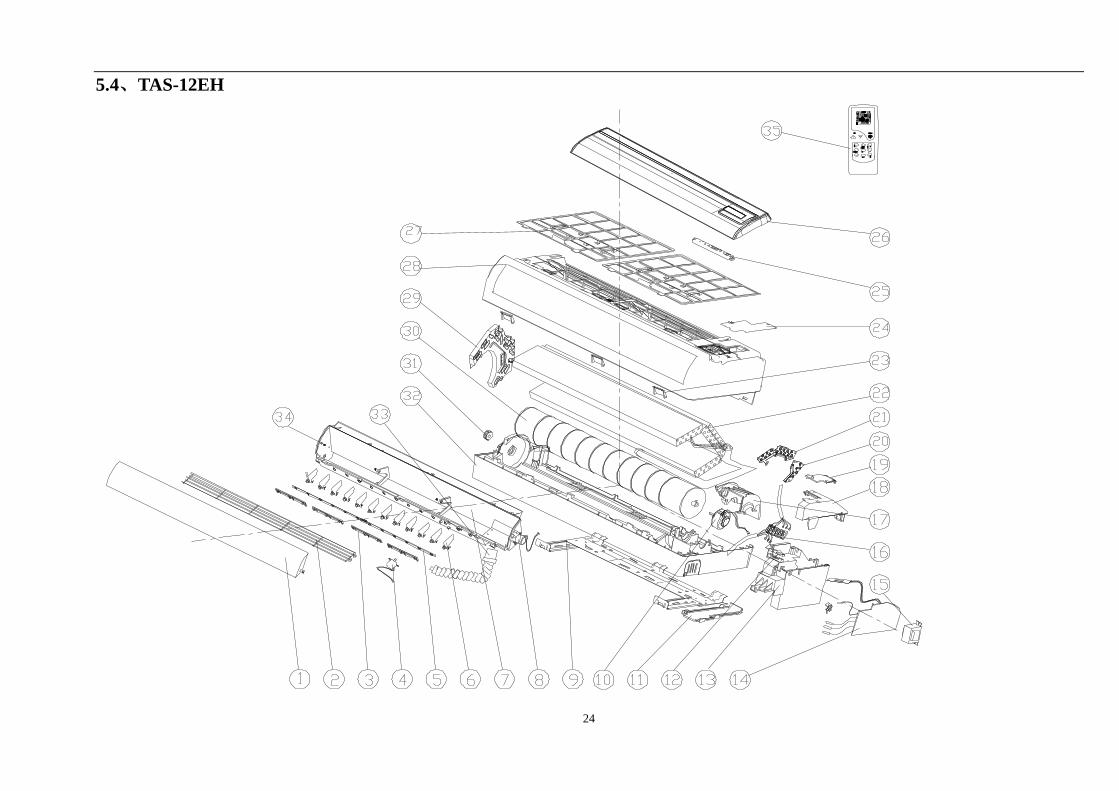
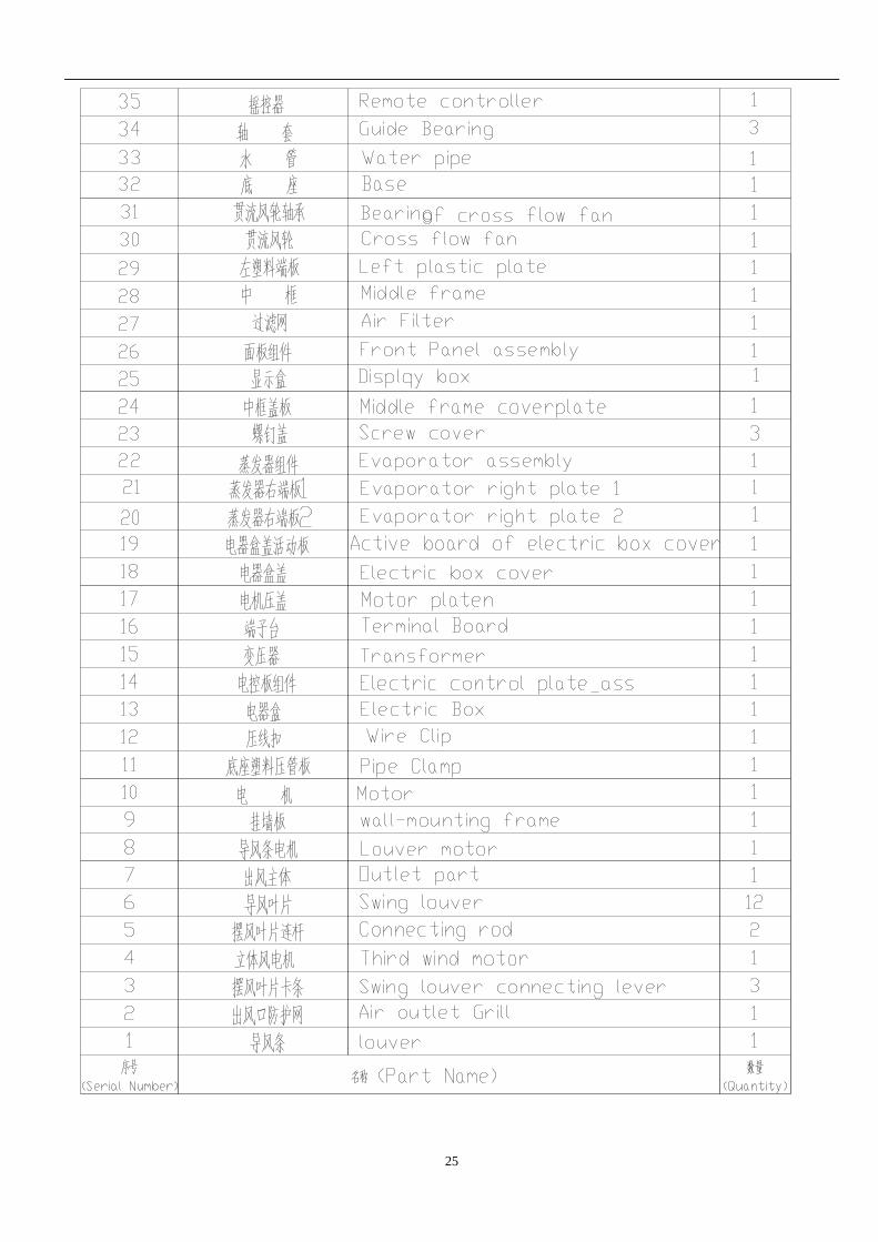
5.4、TAS-12EH
ON
0F F
F
25
26
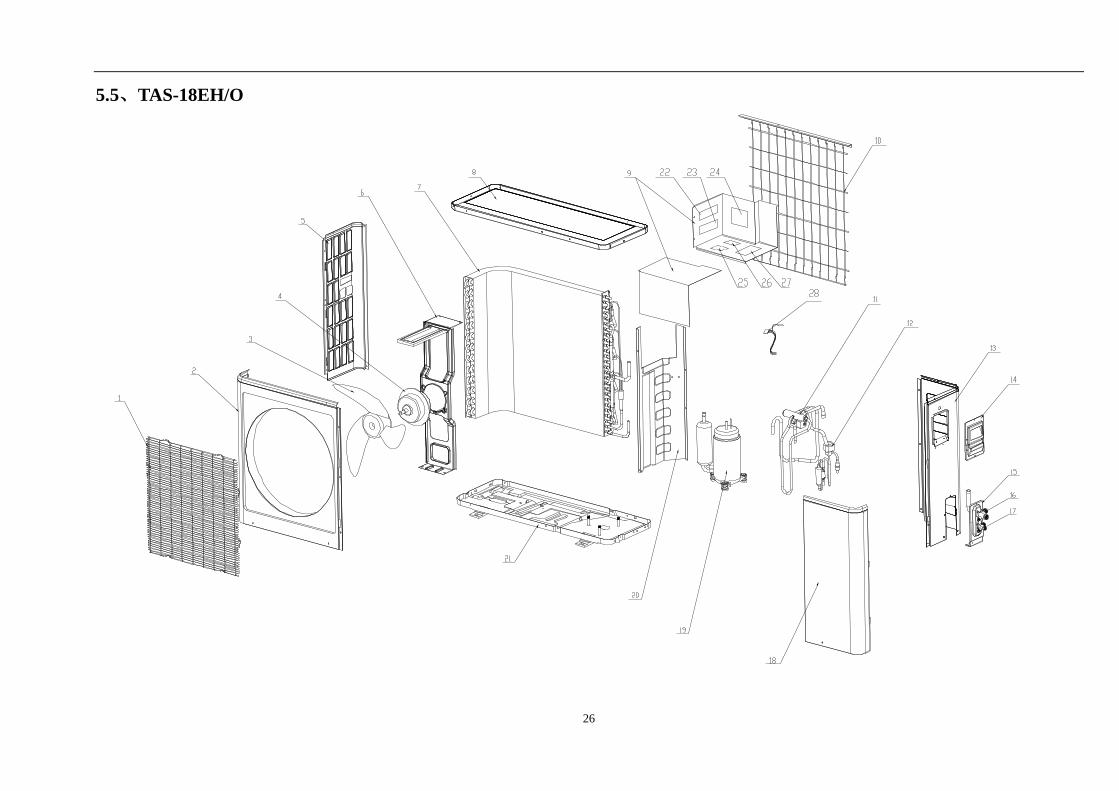
5.5、TAS-18EH/O
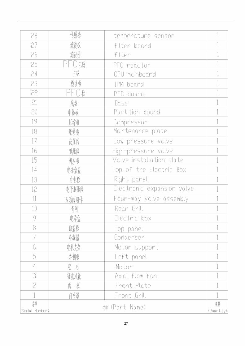
27
28
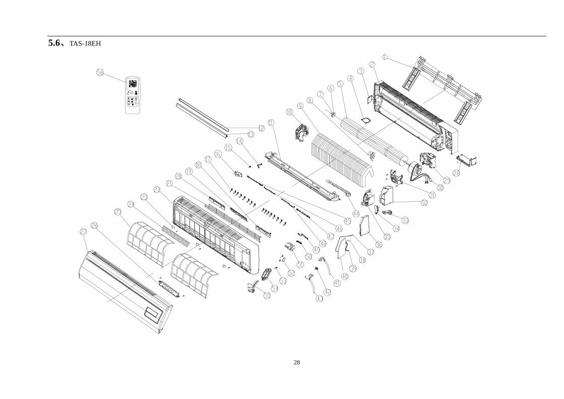
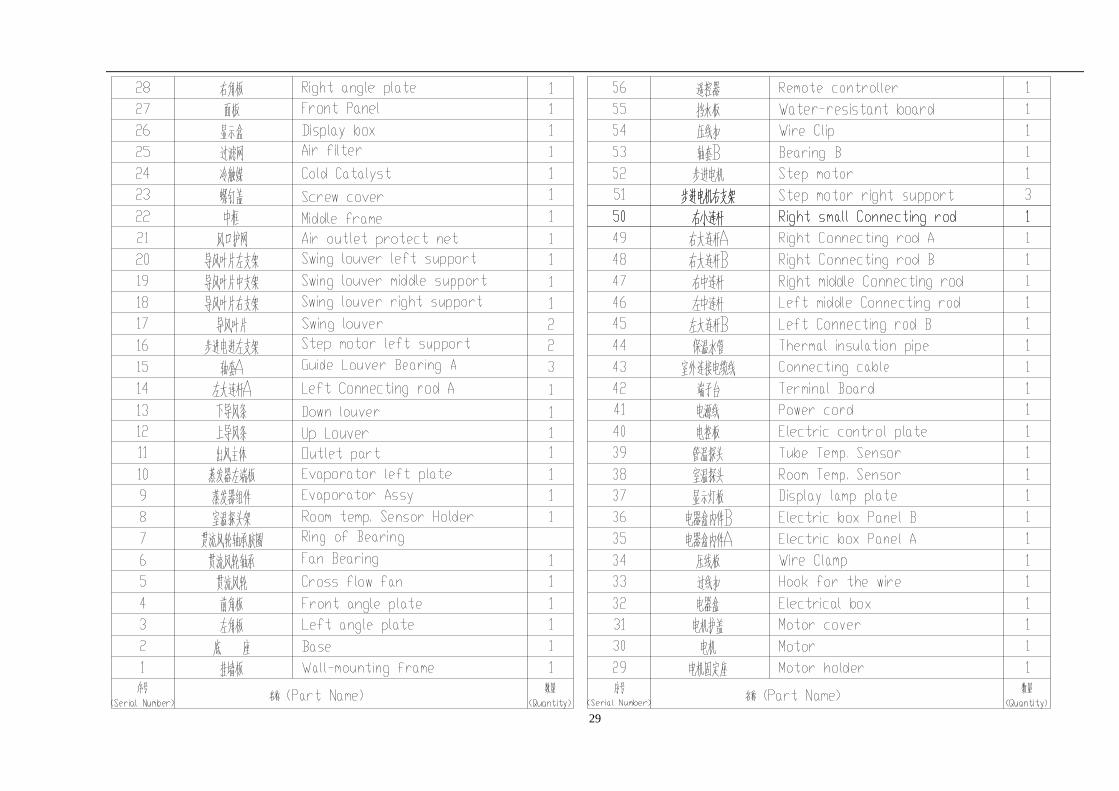
5.6、TAS-18EH
O N
0 FF
F
29
30
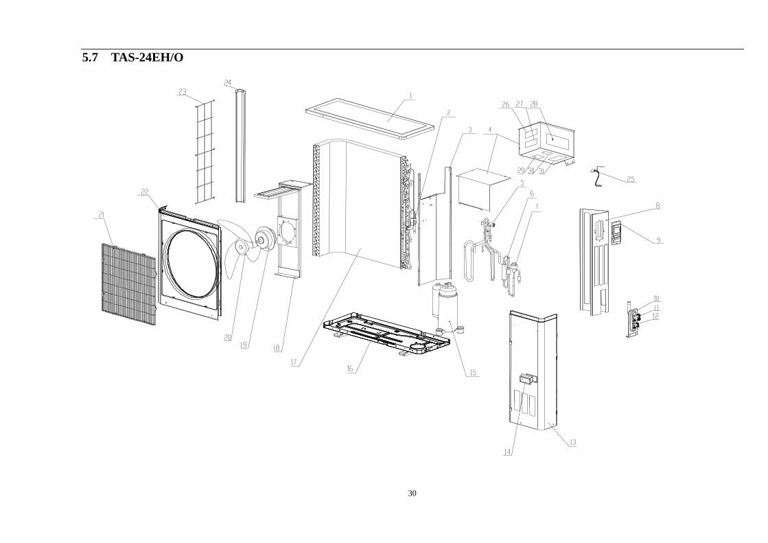
5.7 TAS-24EH/O
31
32
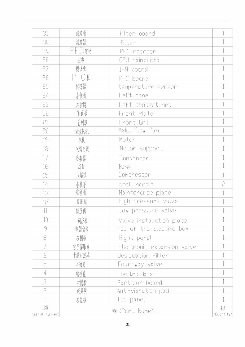
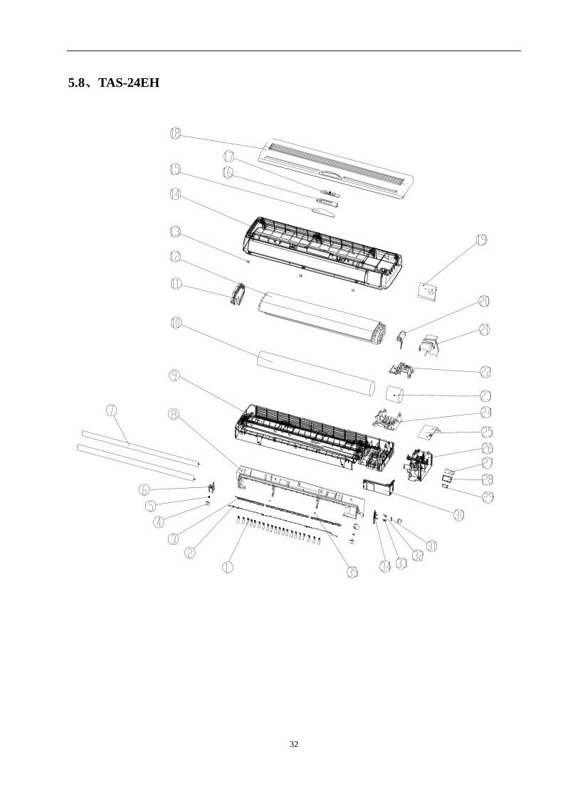
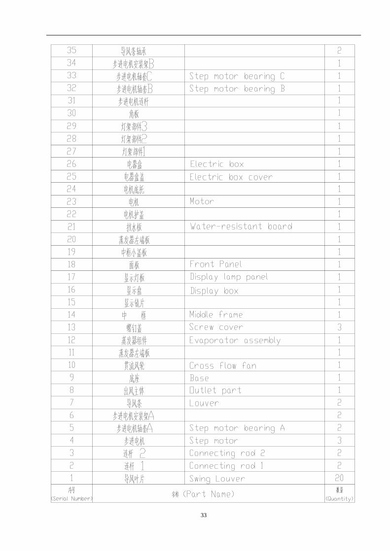
5.8、TAS-24EH
33
34
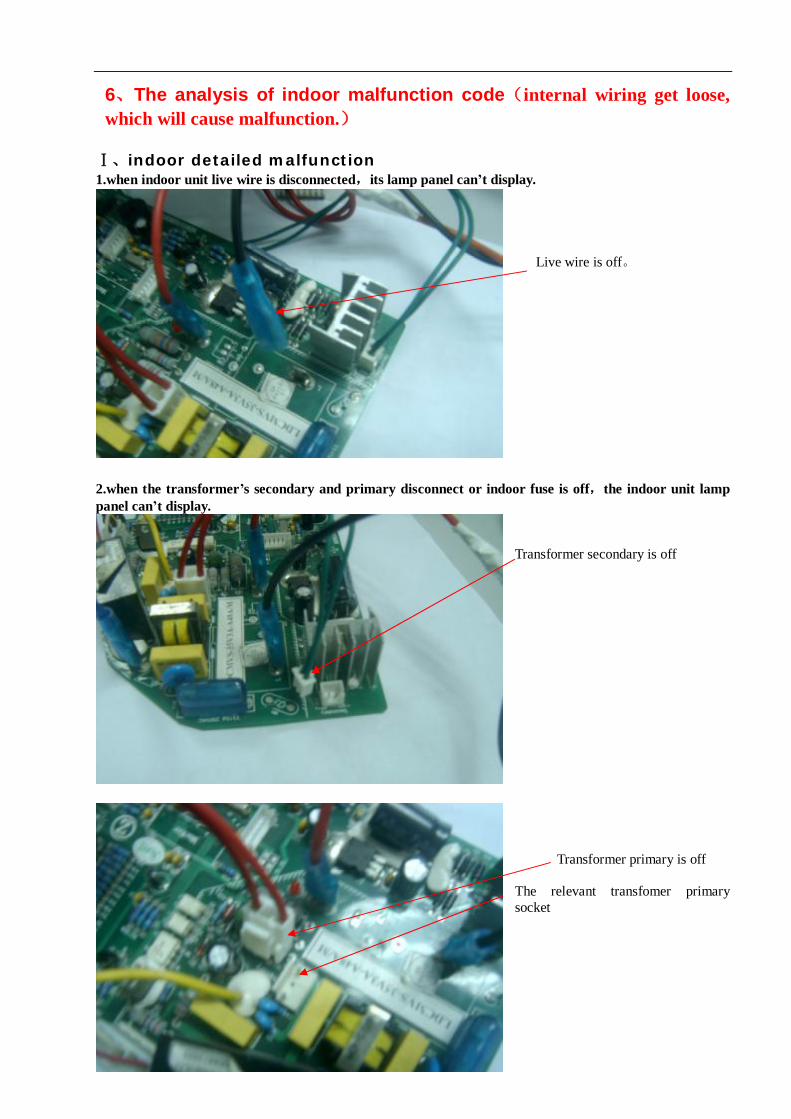
6、The analysis of indoor malfunction code(internal wiring get loose, which will cause malfunction.)
Ⅰ、indoor detailed malfunction 1.when indoor unit live wire is disconnected,its lamp panel can’t display.
Live wire is off。
2.when the transformer’s secondary and primary disconnect or indoor fuse is off,the indoor unit lamp panel can’t display.
Transformer secondary is off Transformer primary is off The relevant transfomer primary socket
35
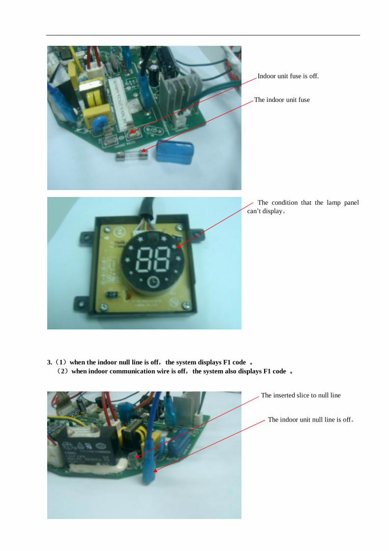
Indoor unit fuse is off. The indoor unit fuse The condition that the lamp panel can’t display。
3.(1)when the indoor null line is off,the system displays F1 code 。 (2)when indoor communication wire is off,the system also displays F1 code 。
The inserted slice to null line The indoor unit null line is off。
36
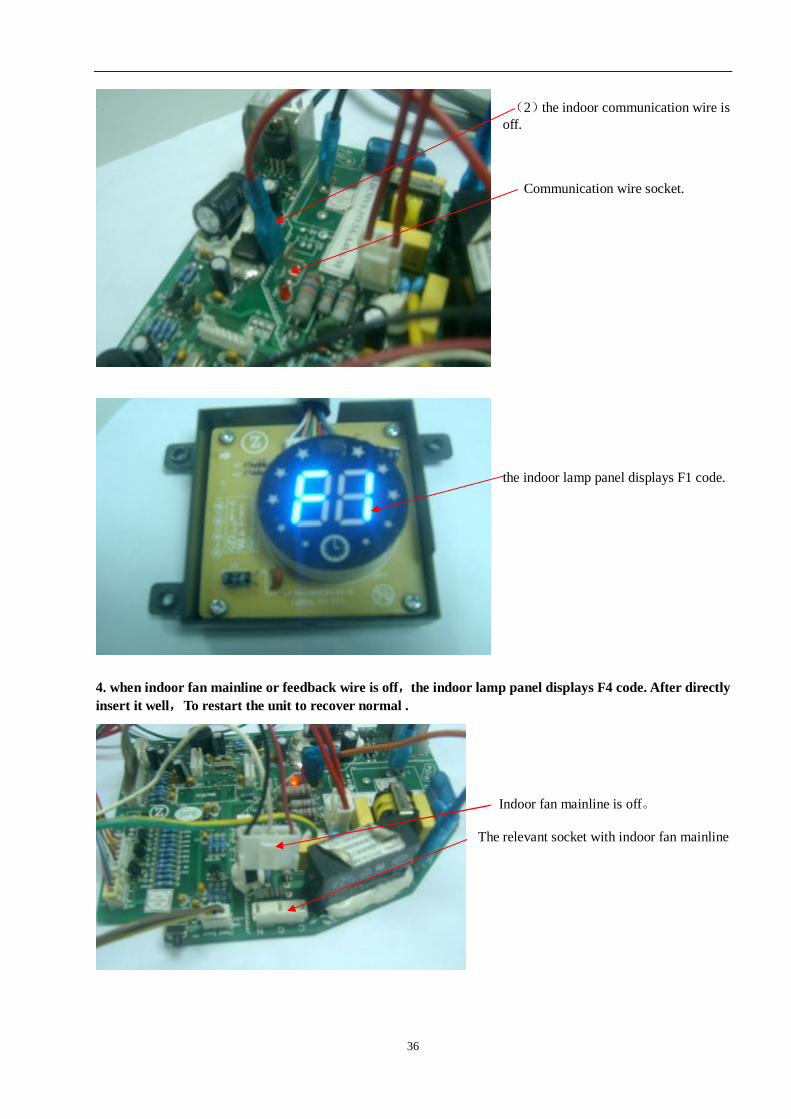
(2)the indoor communication wire is off. Communication wire socket.
the indoor lamp panel displays F1 code.
4. when indoor fan mainline or feedback wire is off,the indoor lamp panel displays F4 code. After directly insert it well,To restart the unit to recover normal .
Indoor fan mainline is off。 The relevant socket with indoor fan mainline
37
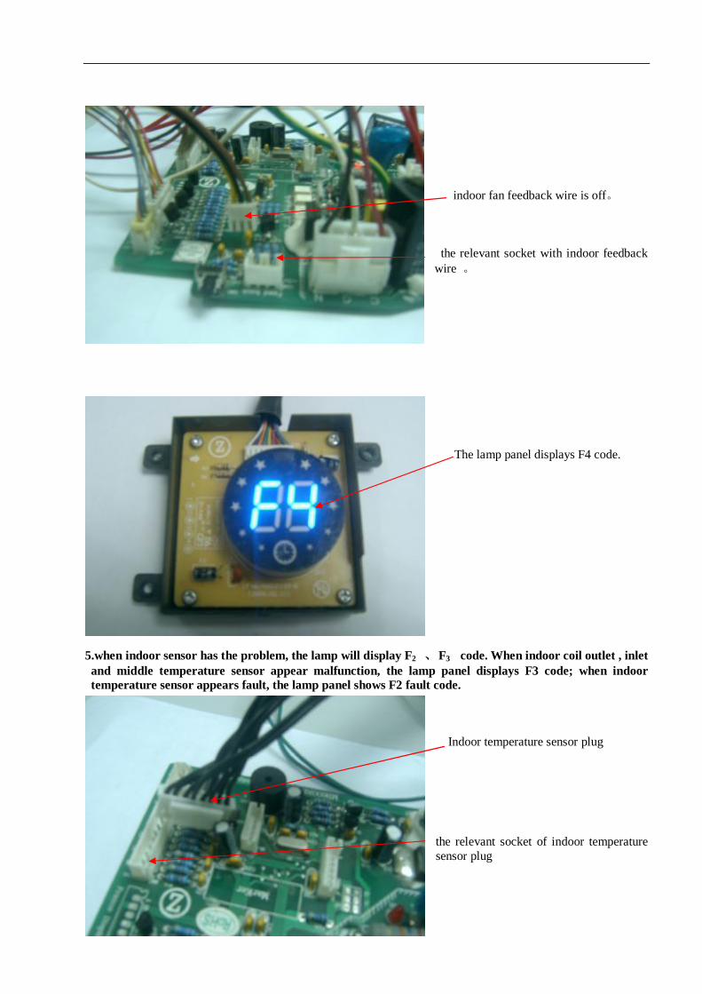
indoor fan feedback wire is off。 the relevant socket with indoor feedback wire 。
The lamp panel displays F4 code.
5.when indoor sensor has the problem, the lamp will display F2 、 F3 code. When indoor coil outlet , inlet and middle temperature sensor appear malfunction, the lamp panel displays F3 code; when indoor temperature sensor appears fault, the lamp panel shows F2 fault code.
Indoor temperature sensor plug
the relevant socket of indoor temperature sensor plug
38
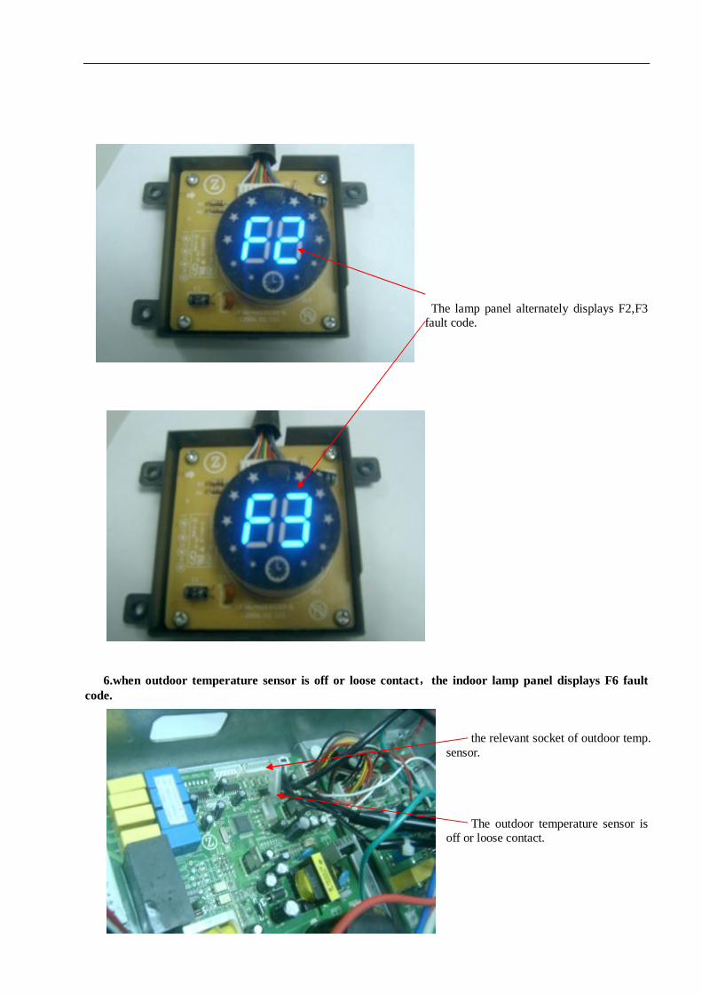
The lamp panel alternately displays F2,F3 fault code.
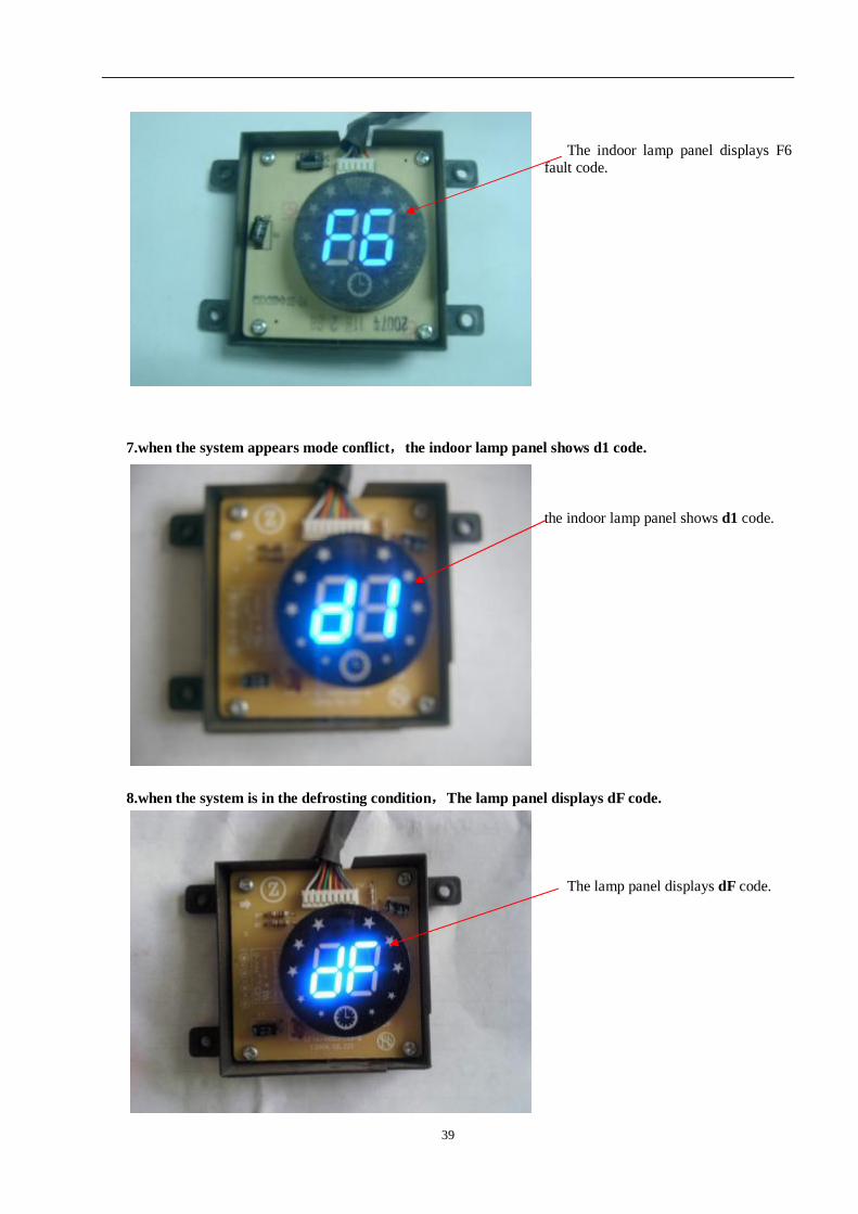
6.when outdoor temperature sensor is off or loose contact,the indoor lamp panel displays F6 fault code.
the relevant socket of outdoor temp. sensor. The outdoor temperature sensor is off or loose contact.
39
The indoor lamp panel displays F6 fault code.
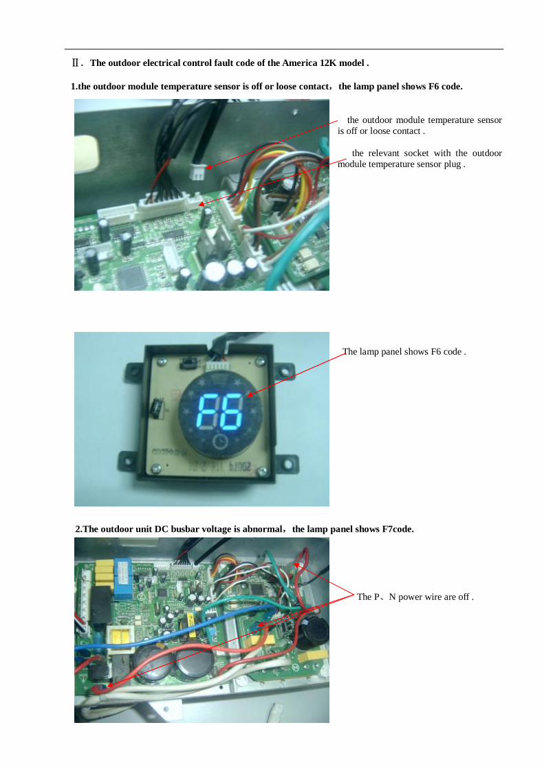
7.when the system appears mode conflict,the indoor lamp panel shows d1 code. the indoor lamp panel shows d1 code.
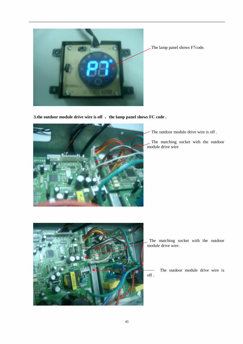
8.when the system is in the defrosting condition,The lamp panel displays dF code.
The lamp panel displays dF code.
40
Ⅱ.The outdoor electrical control fault code of the America 12K model . 1.the outdoor module temperature sensor is off or loose contact,the lamp panel shows F6 code.
the outdoor module temperature sensor is off or loose contact . the relevant socket with the outdoor module temperature sensor plug .
The lamp panel shows F6 code .
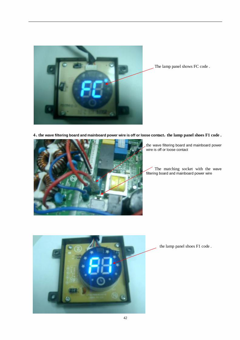
2.The outdoor unit DC busbar voltage is abnormal,the lamp panel shows F7code.
The P、N power wire are off .
41
The lamp panel shows F7code.
3.the outdoor module drive wire is off ,the lamp panel shows FC code .
The outdoor module drive wire is off . The matching socket with the outdoor module drive wire
The matching socket with the outdoor module drive wire .
The outdoor module drive wire is
off .
42
The lamp panel shows FC code .
4、the wave filtering board and mainboard power wire is off or loose contact,the lamp panel shoes F1 code .
the wave filtering board and mainboard power wire is off or loose contact
The matching socket with the wave filtering board and mainboard power wire
the lamp panel shoes F1 code .
43
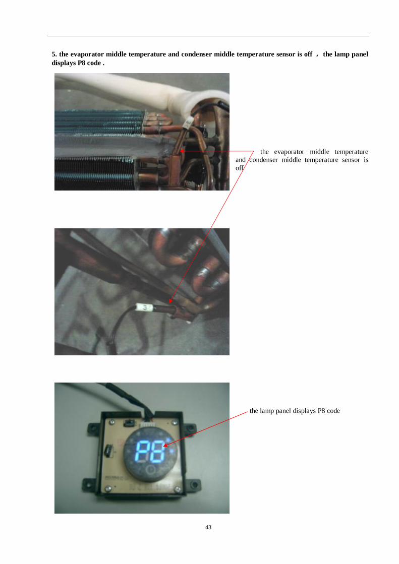
5. the evaporator middle temperature and condenser middle temperature sensor is off ,the lamp panel displays P8 code .
the evaporator middle temperature
and condenser middle temperature sensor is off
the lamp panel displays P8 code
44
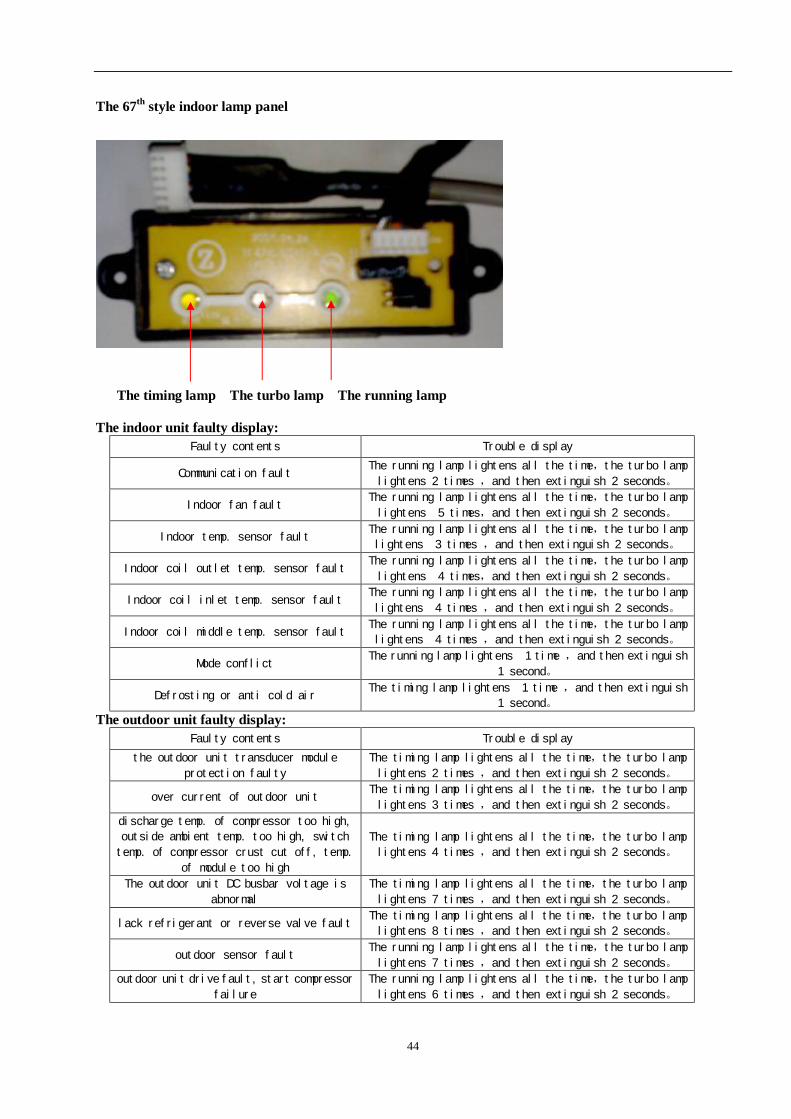
The 67th style indoor lamp panel
The timing lamp The turbo lamp The running lamp The indoor unit faulty display:
Faulty contents Trouble display
Communication fault The running lamp lightens all the time,the turbo lamp
lightens 2 times ,and then extinguish 2 seconds。
Indoor fan fault The running lamp lightens all the time,the turbo lamp
lightens 5 times,and then extinguish 2 seconds。
Indoor temp. sensor fault The running lamp lightens all the time,the turbo lamp
lightens 3 times ,and then extinguish 2 seconds。
Indoor coil outlet temp. sensor fault The running lamp lightens all the time,the turbo lamp
lightens 4 times,and then extinguish 2 seconds。
Indoor coil inlet temp. sensor fault The running lamp lightens all the time,the turbo lamp
lightens 4 times ,and then extinguish 2 seconds。
Indoor coil middle temp. sensor fault The running lamp lightens all the time,the turbo lamp
lightens 4 times ,and then extinguish 2 seconds。
Mode conflict The running lamp lightens 1 time ,and then extinguish
1 second。
Defrosting or anti cold air The timing lamp lightens 1 time ,and then extinguish
1 second。
The outdoor unit faulty display: Faulty contents Trouble display
the outdoor unit transducer module
protection faulty
The timing lamp lightens all the time,the turbo lamp
lightens 2 times ,and then extinguish 2 seconds。
over current of outdoor unit The timing lamp lightens all the time,the turbo lamp
lightens 3 times ,and then extinguish 2 seconds。
discharge temp. of compressor too high,
outside ambient temp. too high, switch
temp. of compressor crust cut off, temp.
of module too high
The timing lamp lightens all the time,the turbo lamp
lightens 4 times ,and then extinguish 2 seconds。
The outdoor unit DC busbar voltage is
abnormal
The timing lamp lightens all the time,the turbo lamp
lightens 7 times ,and then extinguish 2 seconds。
lack refrigerant or reverse valve fault The timing lamp lightens all the time,the turbo lamp
lightens 8 times ,and then extinguish 2 seconds。
outdoor sensor fault The running lamp lightens all the time,the turbo lamp
lightens 7 times ,and then extinguish 2 seconds。
outdoor unit drive fault, start compressor
failure
The running lamp lightens all the time,the turbo lamp
lightens 6 times ,and then extinguish 2 seconds。
45
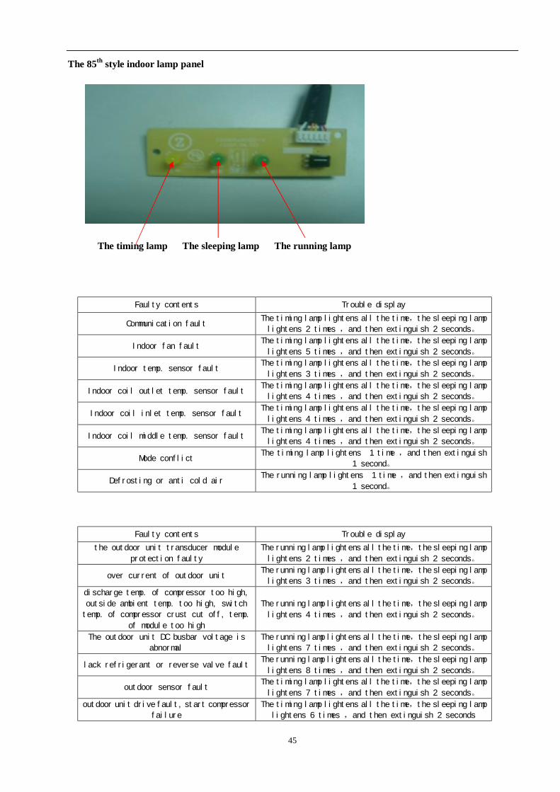
The 85th style indoor lamp panel
The timing lamp The sleeping lamp The running lamp
Faulty contents Trouble display
Communication fault The timing lamp lightens all the time,the sleeping lamp
lightens 2 times ,and then extinguish 2 seconds。
Indoor fan fault The timing lamp lightens all the time,the sleeping lamp
lightens 5 times ,and then extinguish 2 seconds。
Indoor temp. sensor fault The timing lamp lightens all the time,the sleeping lamp
lightens 3 times ,and then extinguish 2 seconds。
Indoor coil outlet temp. sensor fault The timing lamp lightens all the time,the sleeping lamp
lightens 4 times ,and then extinguish 2 seconds。
Indoor coil inlet temp. sensor fault The timing lamp lightens all the time,the sleeping lamp
lightens 4 times ,and then extinguish 2 seconds。
Indoor coil middle temp. sensor fault The timing lamp lightens all the time,the sleeping lamp
lightens 4 times ,and then extinguish 2 seconds。
Mode conflict The timing lamp lightens 1 time ,and then extinguish
1 second。
Defrosting or anti cold air The running lamp lightens 1 time ,and then extinguish
1 second。
Faulty contents Trouble display
the outdoor unit transducer module
protection faulty
The running lamp lightens all the time,the sleeping lamp
lightens 2 times ,and then extinguish 2 seconds。
over current of outdoor unit The running lamp lightens all the time,the sleeping lamp
lightens 3 times ,and then extinguish 2 seconds。
discharge temp. of compressor too high,
outside ambient temp. too high, switch
temp. of compressor crust cut off, temp.
of module too high
The running lamp lightens all the time,the sleeping lamp
lightens 4 times ,and then extinguish 2 seconds。
The outdoor unit DC busbar voltage is
abnormal
The running lamp lightens all the time,the sleeping lamp
lightens 7 times ,and then extinguish 2 seconds。
lack refrigerant or reverse valve fault The running lamp lightens all the time,the sleeping lamp
lightens 8 times ,and then extinguish 2 seconds。
outdoor sensor fault The timing lamp lightens all the time,the sleeping lamp
lightens 7 times ,and then extinguish 2 seconds。
outdoor unit drive fault, start compressor
failure
The timing lamp lightens all the time,the sleeping lamp
lightens 6 times ,and then extinguish 2 seconds
46
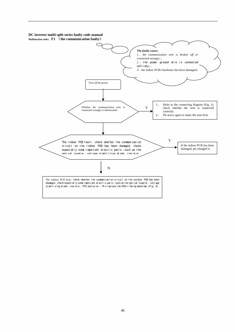
DC inverter multi-split series faulty code manual Malfunction code:F1 (the communication faulty)
Y
Turn off the power
1、 Refer to the connecting diagram (Fig. 1), check whether the wire is connected correctly.
2、 Pls screw again to make the wire firm.
Whether the communication wire is connected wrongly or disentwined.
N The indoor PCB fault,check whether the communication
circuit on the indoor PCB has been damaged, check
especially some important electric parts ,such as the
optical coupler、voltage stabilizing diode、resistor、
Y If the indoor PCB has been damaged, pls changed it.
N
The outdoor PCB fault,check whether the communication circuit on the outdoor PCB has been
damaged,check especially some important electric parts ,such as the optical coupler、voltage
stabilizing diode、resistor、PTC,and so on ;Pls replace the PCB if being abnormal (Fig. 3).
The faulty cause: 1、 the communication wire is broken off or connected wrongiy;、 2 、 the power ground wire is connected
unfirmly;、 3、the indoor PCB’s hardware has been damaged;
47
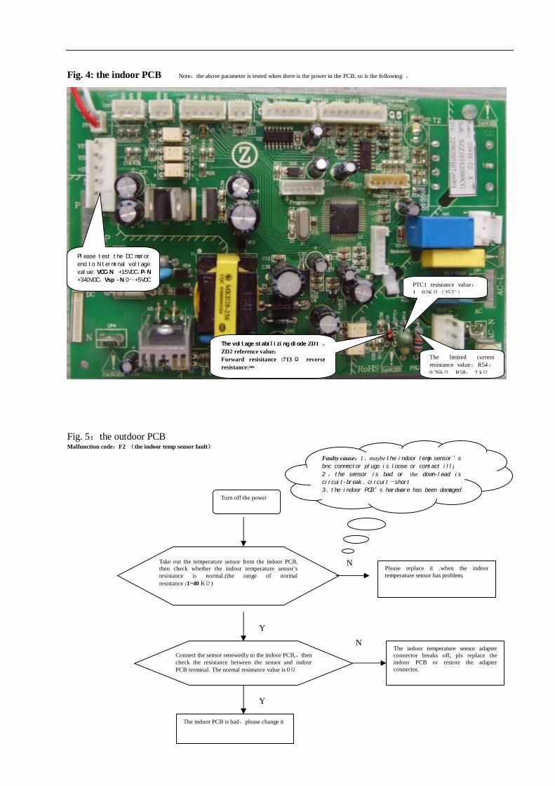
The voltage of the cross flow fan feedback end will be increased gradually from 0 to +2.4VDC when turning on the indoor unit
PTC1 resistance value:1.02KΩ(25℃)
The limited current resistance value:14.8 kΩ
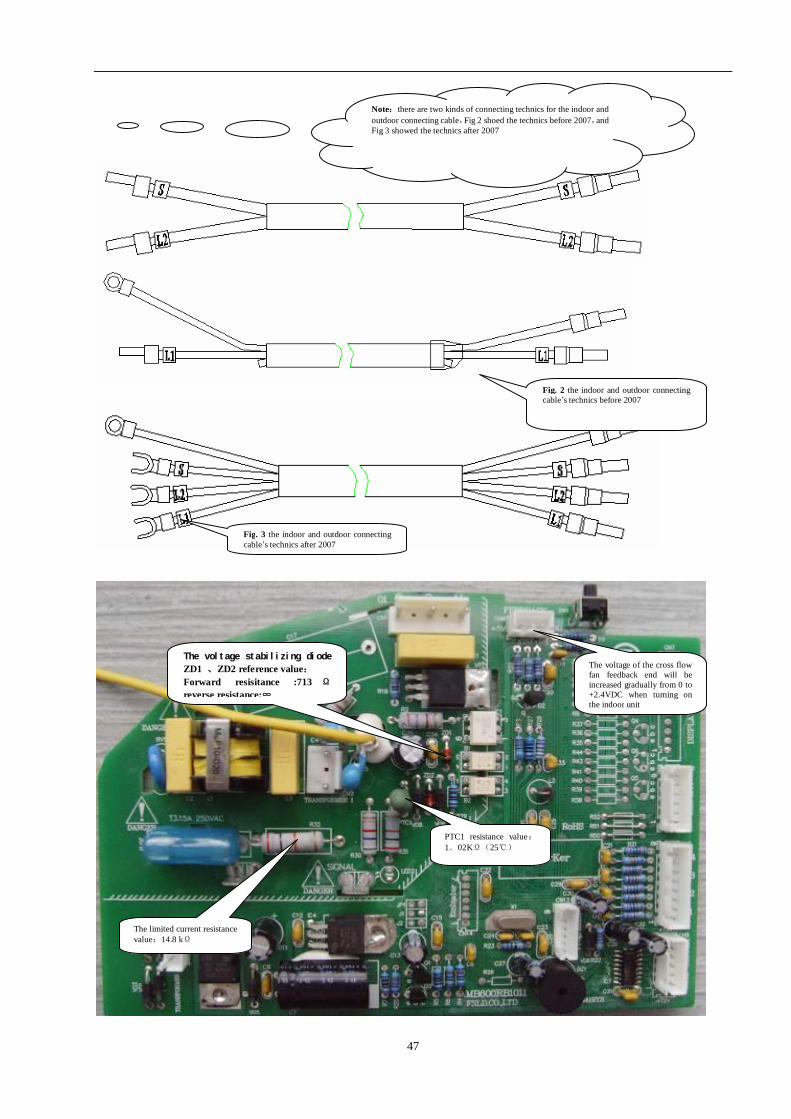
Note:there are two kinds of connecting technics for the indoor and outdoor connecting cable,Fig 2 shoed the technics before 2007,and Fig 3 showed the technics after 2007
Fig. 2 the indoor and outdoor connecting cable’s technics before 2007
Fig. 3 the indoor and outdoor connecting cable’s technics after 2007
The voltage stabilizing diode ZD1 、ZD2 reference value: Forward resisitance :713 Ω reverse resistance:∞
48
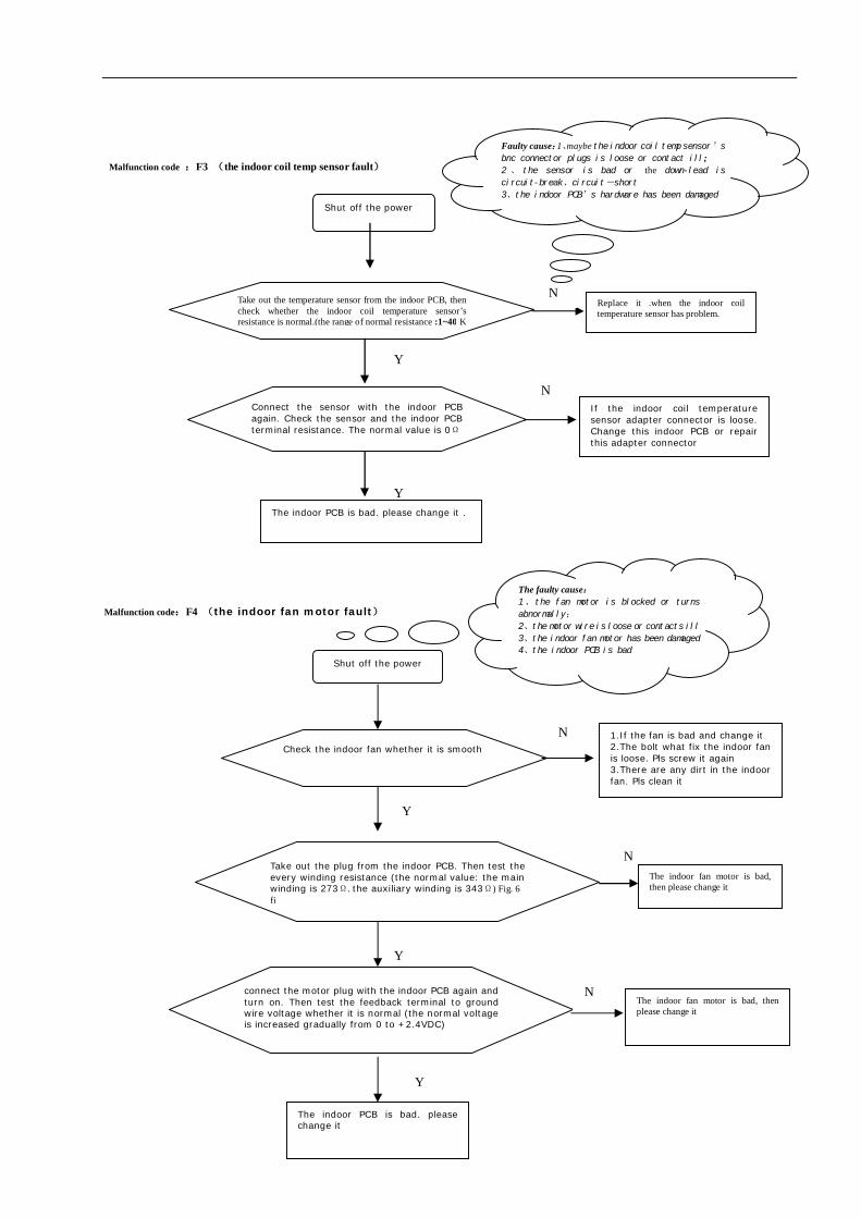
Fig. 4: the indoor PCB Note:the above parameter is tested when there is the power in the PCB, so is the following 。
Fig. 5:the outdoor PCB Malfunction code:F2 (the indoor temp sensor fault)
Turn off the power
Take out the temperature sensor from the indoor PCB, then check whether the indoor temperature sensor’s resistance is normal.(the range of normal resistance :1~40 KΩ)
N Please replace it .when the indoor temperature sensor has problem.
Y
Connect the sensor renewedly to the indoor PCB,,then check the resistance between the sensor and indoor PCB terminal. The normal resistance value is 0Ω
N The indoor temperature sensor adapter connector breaks off, pls replace the indoor PCB or restore the adapter connector.
Y
The indoor PCB is bad,please change it
PTC1 resistance value:1.02KΩ(25℃)
The limited current resistance value:R54: 0.76kΩ R58: 2 kΩ
Faulty cause:1、maybe the indoor temp sensor’s
bnc connector plugs is loose or contact ill; 2 、 the sensor is bad or the down-lead is
circuit-break、circuit-short
3、the indoor PCB’s hardware has been damaged
The voltage stabilizing diode ZD1 、ZD2 reference value: Forward resisitance :713Ω reverse resistance:∞
Please test the DC motor
end to N terminal voltage
value: VCC-N +15VDC、P-N
+340VDC、Vsp -N 0~+5VDC
49
Malfunction code :F3 (the indoor coil temp sensor fault) Malfunction code:F4 (the indoor fan motor fault)
Shut off the power
Take out the temperature sensor from the indoor PCB, then check whether the indoor coil temperature sensor’s resistance is normal.(the range of normal resistance :1~40 K
N Replace it .when the indoor coil temperature sensor has problem.
Y
Connect the sensor with the indoor PCB again. Check the sensor and the indoor PCB terminal resistance. The normal value is 0Ω
N If the indoor coil temperature sensor adapter connector is loose. Change this indoor PCB or repair this adapter connector
Y The indoor PCB is bad. please change it .
Shut off the power
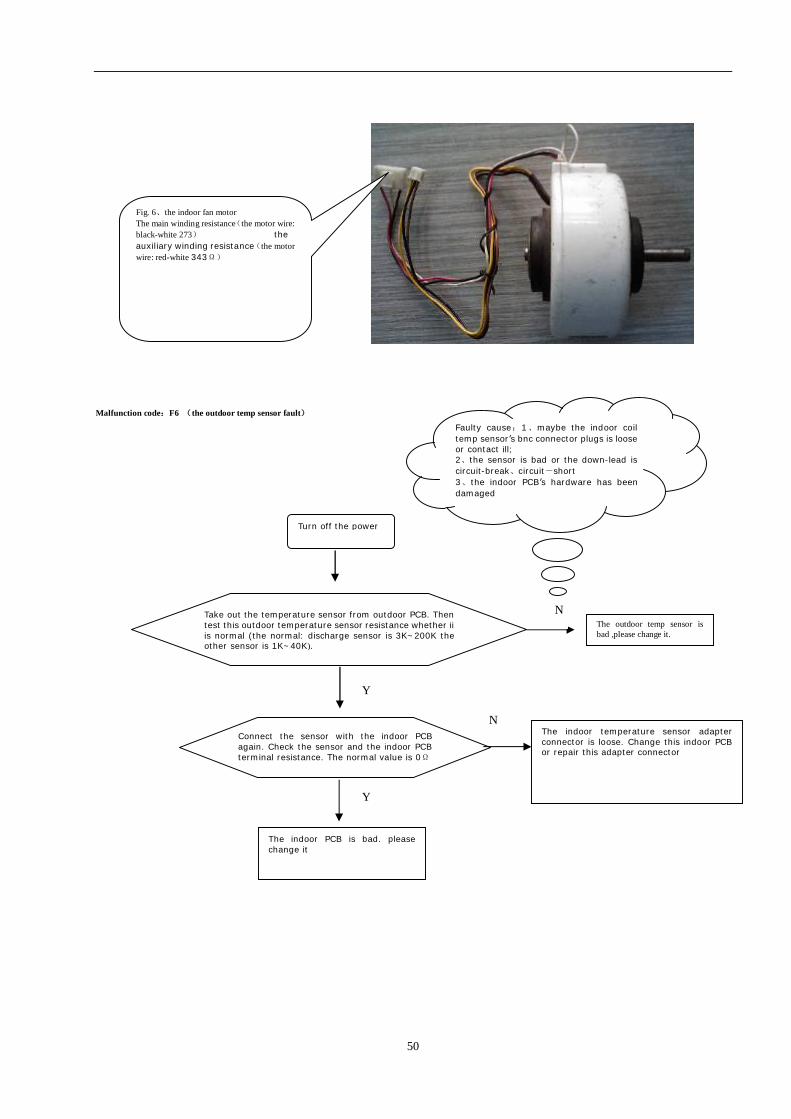
Take out the plug from the indoor PCB. Then test the every winding resistance (the normal value: the main winding is 273Ω. the auxiliary winding is 343Ω) Fig. 6 fi
N The indoor fan motor is bad, then please change it
Y
connect the motor plug with the indoor PCB again and turn on. Then test the feedback terminal to ground wire voltage whether it is normal (the normal voltage is increased gradually from 0 to +2.4VDC)
N The indoor fan motor is bad, then please change it
Y
The indoor PCB is bad. please change it
Check the indoor fan whether it is smooth
N 1.If the fan is bad and change it 2.The bolt what fix the indoor fan is loose. Pls screw it again 3.There are any dirt in the indoor fan. Pls clean it
Y
Faulty cause:1、maybe the indoor coil temp sensor’s
bnc connector plugs is loose or contact ill; 2 、 the sensor is bad or the down-lead is
circuit-break、circuit-short
3、the indoor PCB’s hardware has been damaged
The faulty cause: 1、the fan motor is blocked or turns
abnormally;
2、the motor wire is loose or contacts ill
3、the indoor fan motor has been damaged
4、the indoor PCB is bad
50
Malfunction code:F6 (the outdoor temp sensor fault)
Turn off the power
Take out the temperature sensor from outdoor PCB. Then test this outdoor temperature sensor resistance whether ii is normal (the normal: discharge sensor is 3K~200K the other sensor is 1K~40K).
N The outdoor temp sensor is bad ,please change it.
Y
Connect the sensor with the indoor PCB again. Check the sensor and the indoor PCB terminal resistance. The normal value is 0Ω
N The indoor temperature sensor adapter connector is loose. Change this indoor PCB or repair this adapter connector
Y
The indoor PCB is bad. please change it
Faulty cause:1、maybe the indoor coil temp sensor’s bnc connector plugs is loose or contact ill; 2、the sensor is bad or the down-lead is circuit-break、circuit-short 3、the indoor PCB’s hardware has been damaged
Fig. 6、the indoor fan motor The main winding resistance(the motor wire: black-white 273) the auxiliary winding resistance(the motor wire: red-white 343Ω)
51
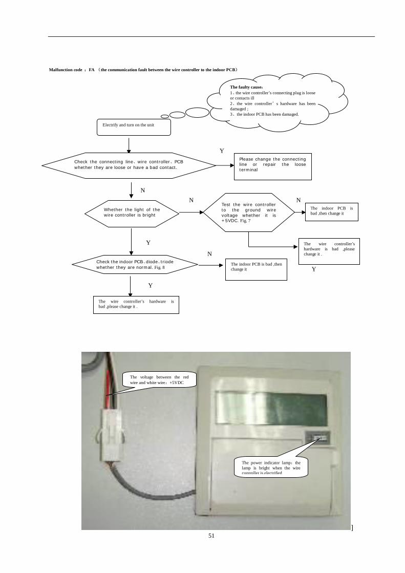
Malfunction code :FA (the communication fault between the wire controller to the indoor PCB)
]
Y
Y
N N
Y
N
N
Electrify and turn on the unit
Check the connecting line、wire controller、PCB whether they are loose or have a bad contact.
Please change the connecting line or repair the loose terminal
Check the indoor PCB、diode、triode whether they are normal. Fig. 8
The wire controller’s hardware is bad ,please change it .
The wire controller’s hardware is bad ,please change it .
Test the wire controller to the ground wire voltage whether it is +5VDC. Fig. 7
Whether the light of the wire controller is bright
The indoor PCB is bad ,then change it
The indoor PCB is bad ,then change it
The faulty cause: 1、the wire controller’s connecting plug is loose or contacts ill 2、the wire controller’s hardware has been damaged ; 3、the indoor PCB has been damaged.
Y
The voltage between the red wire and white wire:+5VDC
The power indicator lamp:the lamp is bright when the wire controller is electrified
52
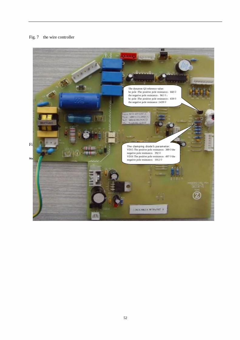
Fig. 7 the wire controller Fig.8 the indoor PCB Malfunction code:P2 (the outdoor unit transducer module protection faulty)
The dynatron Q3 reference value: be pole :The positive pole resistance:660Ω the negative pole resistance:961Ω; bc pole :The positive pole resistance:659Ω the negative pole resistance :1439Ω
The clamping diode’s parameter: VD15 The positive pole resistance:389Ωthe negative pole resistance:392Ω VD16 The positive pole resistance:497Ωthe negative pole resistance:1012Ω
53
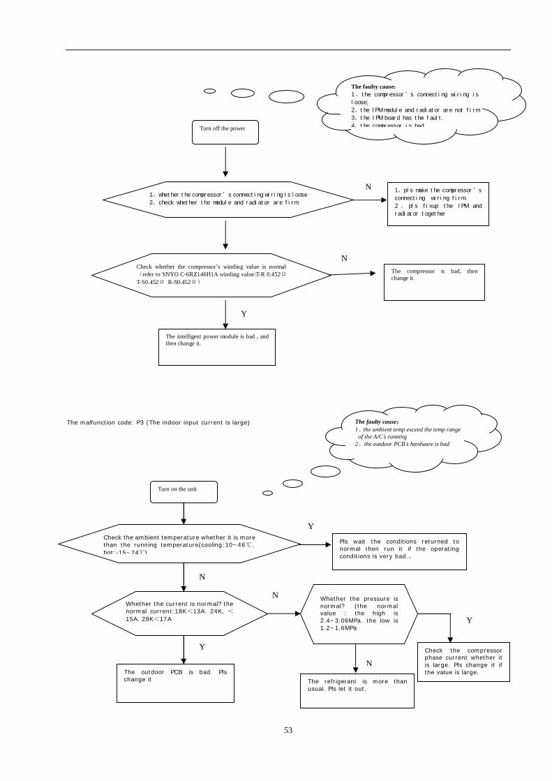
The malfunction code: P3 (The indoor input current is large)
Turn off the power
1、whether the compressor’s connecting wiring is loose
2、check whether the module and radiator are firm
N 1、pls make the compressor’s
connecting wiring firm。
2 、 pls fixup the IPM and
radiator together
Y Check whether the compressor’s winding value is normal(refer to SNYO C-6RZ146H1A winding value:T-R 0.452Ω T-S0.452Ω R-S0.452Ω)
N The compressor is bad, then change it.
The intelligent power module is bad , and then change it.
Y
Y
N
N
Y
N
Y
The faulty cause: 1、the compressor’s connecting wiring is
loose;
2、the IPM module and radiator are not firm
3、the IPM board has the fault.
4、the compressor is bad.
The faulty cause: 1、the ambient temp exceed the temp range
of the A/C’s running 2、the outdoor PCB’s hardware is bad
Turn on the unit
Check the ambient temperature whether it is more than the running temperature(cooling:10~46℃, hot:-15~24℃)
Pls wait the conditions returned to normal then run it if the operating conditions is very bad.。
Whether the current is normal? the normal current:18K<13A. 24K, <15A. 28K<17A
The refrigerant is more than usual. Pls let it out.
The outdoor PCB is bad. Pls change it
Whether the pressure is normal? (the normal value : the high is 2.4~3.06MPa. the low is 1.2~1.6MPa
Check the compressor phase current whether it is large. Pls change it if the value is large.
N
54
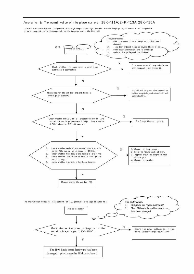
Annotation 1:The normal value of the phase current:18K<11A;24K<13A;28K<15A The malfunction code:P4 (compressor discharge temp is overhigh、outdoor ambient temp go beyond the limited、compressor
crustal temp switch is disconnected、module temp go beyond the limited)
The malfunction code: P7 (The outdoor unit DC generatrix voltage is abnormal)
Turn off the power
Check whether the compressor crustal temp
switch is disconnected.
YCompressor crustal temp switch has
been damaged,then change it。
N
Check whether the outdoor ambient temp is
overhigh or overlow.
Y The fault will disappear when the outdoor ambient temp is beyond minus 20℃ and under plus 55℃.
N Pls Charge the refrigerant.
N
Check whether the A/C units’ pressure is normal(the
normal value:high pressure 3.06Mpa low pressure
1.6Mpa)when the A/C unit operate
Y
2、 check whether module temp sensor’resistance is
normal (the normal value range:1~40KΩ);
3、 check whether the module and radiator are firm;
4、 check whether the disperse heat silica gel is
short or dry;
5、 check whether the module has been damaged.
N 1、Change the temp sensor;
2、Firm the module and radiator;
3、 Append anew the disperse heat
silica gel;
4、Change the module。
Y
Please change the outdoor PCB
Turn off the supply
Check whether the power voltage is in the
normal voltage range “150V~270V”。
N Ensure the power voltage is in the
normal voltage range“150V~270V”
Y
The IPM basic board hardware has been damaged,pls change the IPM basic board。
The faulty cause: 2、 the compressor crustal temp switch has been
damaged 3、 、outdoor ambient temp go beyond the limited 4、 compressor discharge temp is overhigh 5、 module temp go beyond the limited
The faulty cause: 1、 The power voltage is abnormal 2、 The IPM basic board hardware
has been damaged
55
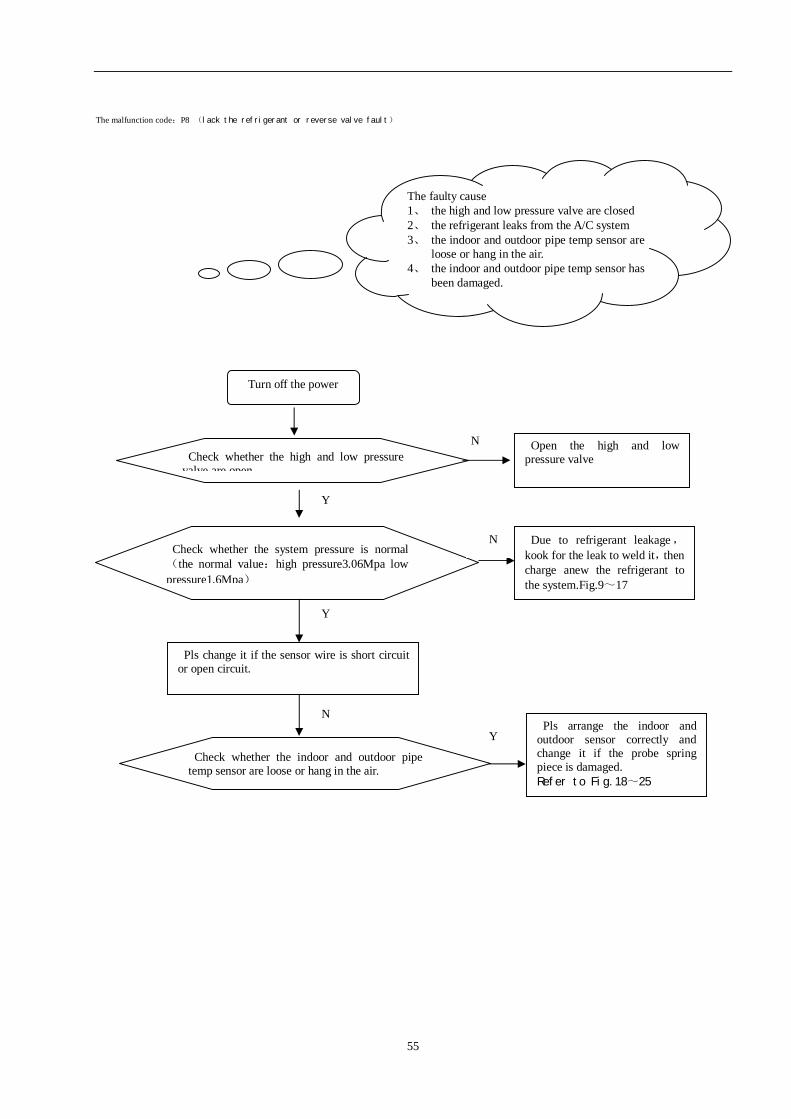
The malfunction code:P8 (lack the refrigerant or reverse valve fault)
Turn off the power
Check whether the high and low pressure valve are open
N Open the high and low pressure valve
正常
Check whether the system pressure is normal(the normal value:high pressure3.06Mpa low pressure1.6Mpa)
N Due to refrigerant leakage,kook for the leak to weld it,then charge anew the refrigerant to the system.Fig.9~17
Pls change it if the sensor wire is short circuit or open circuit.
N
Y
Check whether the indoor and outdoor pipe temp sensor are loose or hang in the air.
Y
Pls arrange the indoor and outdoor sensor correctly and change it if the probe spring piece is damaged. Refer to Fig.18~25
Y
The faulty cause 1、 the high and low pressure valve are closed 2、 the refrigerant leaks from the A/C system 3、 the indoor and outdoor pipe temp sensor are
loose or hang in the air. 4、 the indoor and outdoor pipe temp sensor has
been damaged.
56
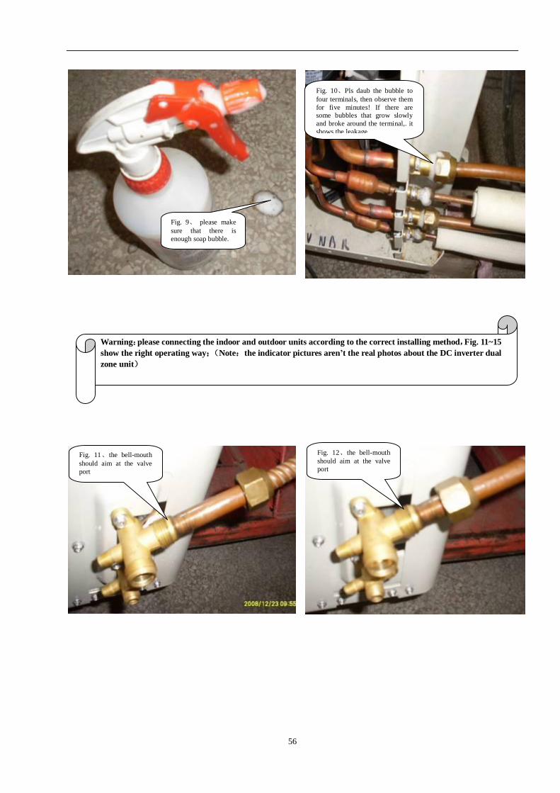
Fig. 11、the bell-mouth should aim at the valve port
Fig. 12、the bell-mouth should aim at the valve port
Fig. 9、 please make sure that there is enough soap bubble.
Warning:please connecting the indoor and outdoor units according to the correct installing method,Fig. 11~15 show the right operating way;(Note:the indicator pictures aren’t the real photos about the DC inverter dual zone unit)
Fig. 10、Pls daub the bubble to four terminals, then observe them for five minutes! If there are some bubbles that grow slowly and broke around the terminal,. it shows the leakage
57
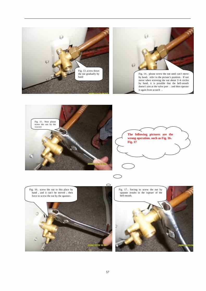
The following pictures are the wrong operation. such as Fig. 16、Fig. 17
Fig. 14、please screw the nut until can’t move by hand,refer to the picture’s position。If not move when screwing the nut about 3~4 circles by hand, it is possible that the bell-mouth doesn’t aim at the valve port ,and then operate it again from scratch 。
Fig. 13、screw down the nut gradually by hand
Fig. 15、Next please screw the nut by the spanner.
Fig. 16、screw the nut to this place by hand , and it can’t be moved ; then force to screw the nut by the spanner。
Fig. 17、forcing to screw the nut by spanner results in the rupture of the bell-mouth.
58
The spring gasket
The spring gasket
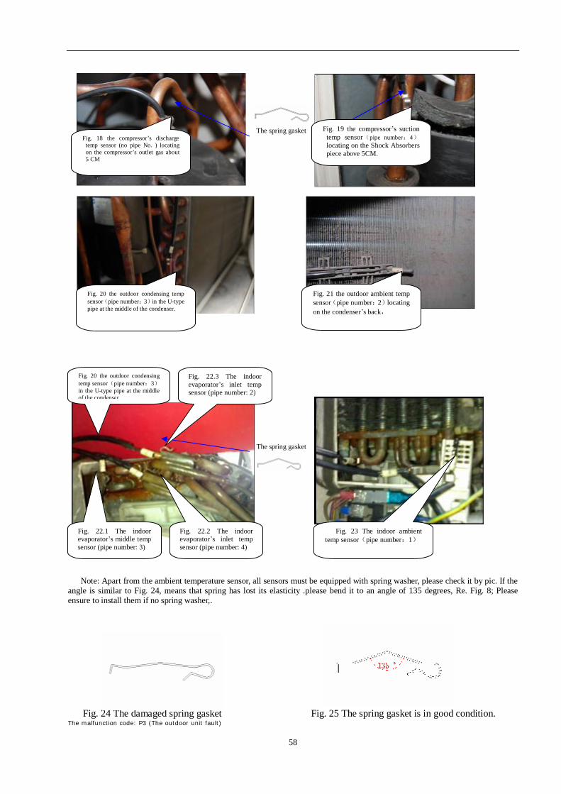
Note: Apart from the ambient temperature sensor, all sensors must be equipped with spring washer, please check it by pic. If the angle is similar to Fig. 24, means that spring has lost its elasticity .please bend it to an angle of 135 degrees, Re. Fig. 8; Please ensure to install them if no spring washer,.
Fig. 24 The damaged spring gasket Fig. 25 The spring gasket is in good condition.
The malfunction code: P3 (The outdoor unit fault)
Fig. 20 the outdoor condensing temp sensor(pipe number:3)in the U-type pipe at the middle of the condenser.
Fig. 21 the outdoor ambient temp sensor(pipe number:2)locating on the condenser’s back,
Fig. 18 the compressor’s discharge temp sensor (no pipe No. ) locating on the compressor’s outlet gas about 5 CM
Fig. 19 the compressor’s suction temp sensor(pipe number:4)locating on the Shock Absorbers piece above 5CM.
Fig. 20 the outdoor condensing temp sensor(pipe number:3)in the U-type pipe at the middle of the condenser.
Fig. 23 The indoor ambient temp sensor(pipe number:1)
Fig. 22.1 The indoor evaporator’s middle temp sensor (pipe number: 3)
Fig. 22.2 The indoor evaporator’s inlet temp sensor (pipe number: 4)
Fig. 22.3 The indoor evaporator’s inlet temp sensor (pipe number: 2)
59
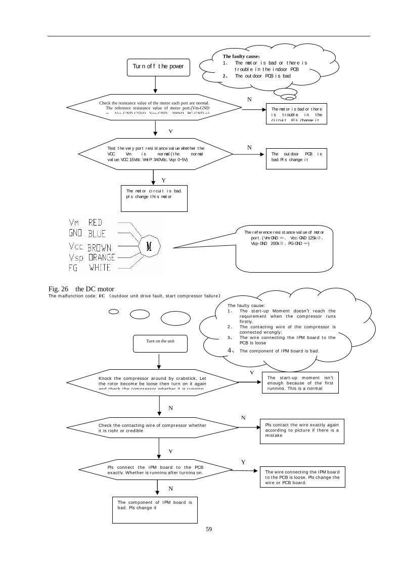
Fig. 26 the DC motor The malfunction code: FC (outdoor unit drive fault, start compressor failure)
Turn off the power
Check the resistance value of the motor each port are normal. The reference resistance value of motor port.(Vm-GND ∞、 Vcc-GND 125kΩ、Vsp-GND 200kΩ、PG-GND ∞)
N The motor is bad or there
is trouble in the
circuit. Pls change it
Y
Test the very port resistance value whether the
VCC Vm is normal(the normal
value:VCC:15Vdc.Vm/P:340Vdc.Vsp:0~5V)
Y
The outdoor PCB is
bad.Pls change it
The motor circuit is bad.
pls change this motor
Turn on the unit
Knock the compressor around by crabstick. Let the rotor become be loose then turn on it again and check the compressor whether it is running.
Y The start-up moment isn’t enough because of the first running. This is a normal
Y
Check the contacting wire of compressor whether it is right or credible
N
Pls contact the wire exactly again according to picture if there is a mistake
The component of IPM board is bad. Pls change it
N
Pls connect the IPM board to the PCB exactly. Whether is running after turning on.
Y The wire connecting the IPM board
to the PCB is loose. Pls change the wire or PCB board.
N
The faulty cause: 1、 The motor is bad or there is
trouble in the indoor PCB
2、 The outdoor PCB is bad
The faulty cause: 1、 The start-up Moment doesn’t reach the
requirement when the compressor runs firstly.
2、 The contacting wire of the compressor is connected wrongly;
3、 The wire connecting the IPM board to the PCB is loose
4、 The component of IPM board is bad.
The reference resistance value of motor
port.(Vm-GND ∞、 Vcc-GND 125kΩ、
Vsp-GND 200kΩ、PG-GND ∞)
N