Embed Size (px)
Citation preview
7/27/2019 Pu 10 4roy-Mayhew
http://slidepdf.com/reader/full/pu-10-4roy-mayhew 1/9
Functionalized Graphene as a CatalyticCounter Electrode in Dye-SensitizedSolar CellsJoseph D. Roy-Mayhew, David J. Bozym, Christian Punckt, and Ilhan A. Aksay*
Department of Chemical and Biological Engineering, Princeton University, Princeton, New Jersey 08544, United States
Dye-sensitized solar cells (DSSCs)
have received much attention as
an alternative to silicon-based so-
lar cells due to their potential low cost, easy
fabrication, and respectable energy conver-
sion efficiency (over 10%).1,2 In typical DSSC
architectures, the photon-induced oxida-
tion of a dye occurs at a TiO2 photoanode,
while the reduction of the redox species
used to regenerate the dye occurs at the
counter electrode. The standard redox
couple used for dye regeneration, iodide/
triiodide (IϪ /I3Ϫ), has unmatched perfor-
mance but typically requires a platinum
catalyst in DSSC operation.3Ϫ5 Platinum has
high catalytic activity toward I3Ϫ reduction
and is sufficiently corrosion-resistant to iodo
species present in the electrolyte.6Ϫ9 How-
ever, since platinum is a precious metal,
much incentive exists to develop DSSC
counter electrodes using cheaper, abun-
dant materials. Extensive research has, for
example, been performed on using carbon-
aceous materials for the counter electrode
because they are low cost, corrosion resis-
tant, and electrically conductive.9Ϫ18 While
graphite has poor catalytic activity toward
the reduction of I3Ϫ, its high surface area
analogs, such as carbon black and carbon
nanotubes, have been shown to be quite ef-
fective and in some cases even exceeded
the performance of platinum.18Ϫ20 Very re-
cently, graphene composites have emerged
as potential catalysts for DSSC cathodes,
due to graphene’s exceptional surface area
and conductivity.21Ϫ23 Hong et al ., for ex-
ample, have used a chemically reduced
graphite oxide derived graphene/poly(3,4-
ethylenedioxythiophene) poly(styrene-
sulfonate) (PEDOT:PSS) composite and
achieved efficiencies of 4.5%, comparable
to their platinum control cell at 6.3%. It has
been suggested that oxygen-containing
functional groups might be responsible for
the observed catalytic performance of car-
bonaceous electrode materials, while theimpact of the degree of material functional-
ization on apparent electrocatalytic perfor-
mance has not been studied in detail.16,24
In this paper, we provide a thorough
analysis of DSSC cathodes based on func-
tionalized graphene sheets (FGSs), a type of
defective graphene currently synthesized
at the industrial scale25 via the thermal exfo-
liation of graphite oxide (GO), detailed
elsewhere.26,27 FGSs have a large surface
area (up to 2630 m2 gϪ1) and contain lat-
tice defects and oxygen-containing func-tional groups, such as hydroxyls, carbonyls,
and epoxides, as shown in Figure 1.27Ϫ29 The
amount of oxygen-containing groups can
be tuned by thermal processing of the ma-
terial, thereby changing its carbon to oxy-
gen (C/O) ratio.26 Thermal treatment up to
ϳ1000 °C decreases the number of oxygen-
containing functional groups on the sur-
face of the sheets and increases the FGS
conductivity. Furthermore, annealing at
temperatures above ϳ1500 °C causes heal-
ing of lattice defects.28,30 An advantage of
*Address correspondence to
Received for review July 14, 2010
and accepted September 22, 2010.
Published onlineOctober 12, 2010.
10.1021/nn1016428
© 2010 American Chemical Society
ABSTRACT When applied on the counter electrode of a dye-sensitized solar cell, functionalized graphene
sheets with oxygen-containing sites perform comparably to platinum (conversion efficiencies of 5.0 and 5.5%,
respectively, at 100 mW cm 2 AM1.5G simulated light). To interpret the catalytic activity of functionalized
graphene sheets toward the reduction of triiodide, we propose a new electrochemical impedance spectroscopy
equivalent circuit that matches the observed spectra features to the appropriate phenomena. Using cyclic
voltammetry, we also show that tuning our material by increasing the amount of oxygen-containing functional
groups can improve its apparent catalytic activity. Furthermore, we demonstrate that a functionalized graphene
sheet based ink can serve as a catalytic, flexible, electrically conductive counter electrode material.
KEYWORDS: graphene · dye-sensitized solar cell · counter electrode ·iodide/triiodide catalyst · charge-transfer resistance · flexible
A R T
I C L E
www.acsnano.org VOL. 4 ▪ NO. 10 ▪ 6203–6211 ▪ 2010 6203
7/27/2019 Pu 10 4roy-Mayhew
http://slidepdf.com/reader/full/pu-10-4roy-mayhew 2/9
our material is that we can systematically adjust the
C/O ratio of the FGS to examine its effect on the cata-
lytic activity of the material. To distinguish the compo-
sitions of FGSs, we designate them as FGS x , where x de-notes the C/O ratio.
In the following, we first show that FGSs can func-
tion as the catalytic counter electrode material in a
fully assembled DSSC with a performance similar to
that of platinum. Based on these results and supple-
mentary electrochemical impedance spectroscopy (EIS)
measurements on the FGS counter electrode itself, in
which we vary the applied bias as well as electrolyte vis-
cosity and concentration, we propose a new approach
to interpret impedance spectra for porous carbon elec-
trodes. We use this interpretation to properly quantify
the charge-transfer resistance of FGS counter elec-trodes. To support our EIS data, we then investigate
the catalytic activity of FGSs in more detail using cyclic
voltammetry (CV). Although the optimization of FGS
counter electrodes is beyond the scope of this work,
we explore the effect of functionalization as measured
by C/O ratio as well as the effect of electrode morphol-
ogy on the apparent catalytic activity of FGSs. Finally,
we utilize the industrial scale production of the material
to demonstrate DSSC operation using a commercially
available25 FGS-based ink that can be cast on noncon-
ductive elastomeric surfaces as the counter electrode.
RESULTS AND DISCUSSION
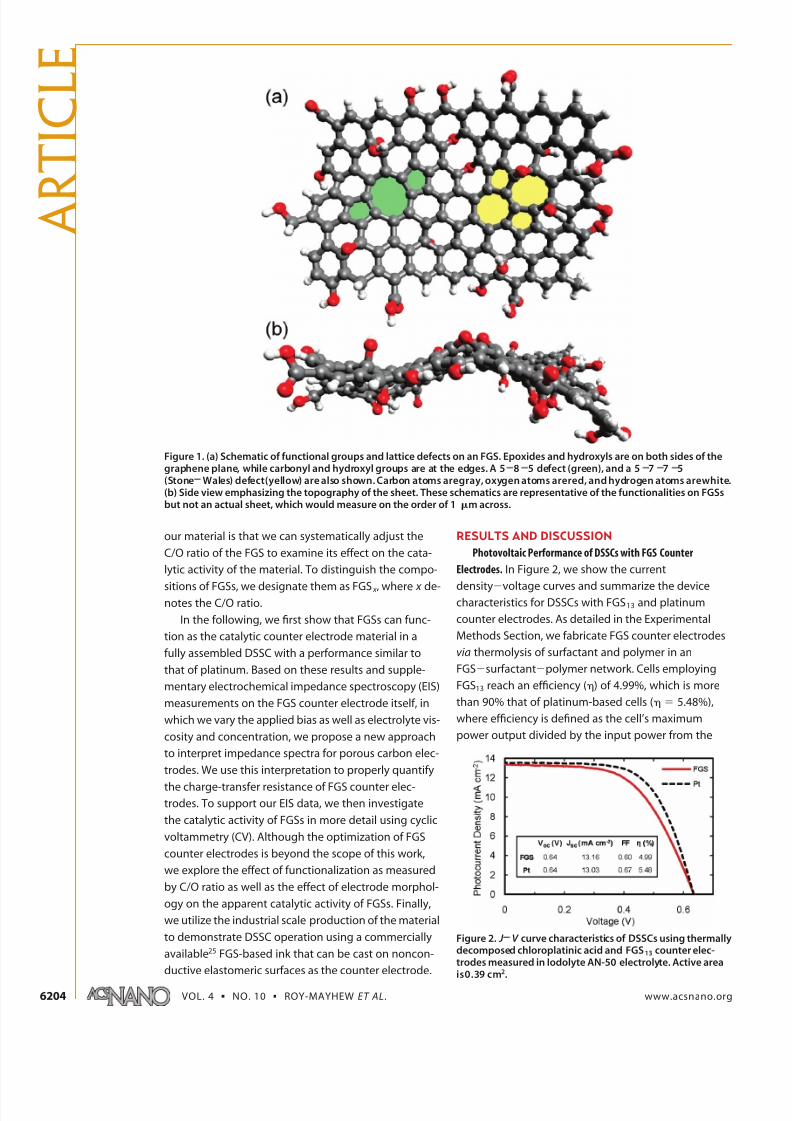
Photovoltaic Performance of DSSCs with FGS Counter
Electrodes. In Figure 2, we show the current
densityϪvoltage curves and summarize the devicecharacteristics for DSSCs with FGS13 and platinum
counter electrodes. As detailed in the Experimental
Methods Section, we fabricate FGS counter electrodes
via thermolysis of surfactant and polymer in an
FGSϪsurfactantϪpolymer network. Cells employing
FGS13 reach an efficiency () of 4.99%, which is more
than 90% that of platinum-based cells ( ϭ 5.48%),
where efficiency is defined as the cell’s maximum
power output divided by the input power from the
Figure 1. (a) Schematic of functional groups and lattice defects on an FGS. Epoxides and hydroxyls are on both sides of thegraphene plane, while carbonyl and hydroxyl groups are at the edges. A 5 8 5 defect (green), and a 5 7 7 5(Stone Wales) defect(yellow) are also shown. Carbon atoms aregray, oxygen atoms arered, and hydrogen atoms arewhite.(b) Side view emphasizing the topography of the sheet. These schematics are representative of the functionalities on FGSsbut not an actual sheet, which would measure on the order of 1 m across.
Figure 2. J V curve characteristics of DSSCs using thermallydecomposed chloroplatinic acid and FGS13 counter elec-trodes measured in Iodolyte AN-50 electrolyte. Active areais0.39 cm2.
A R
T I C L E
VOL. 4 ▪ NO. 10 ▪ ROY-MAYHEW ET AL. www.acsnano.org6204
7/27/2019 Pu 10 4roy-Mayhew
http://slidepdf.com/reader/full/pu-10-4roy-mayhew 3/9
light source. Both types exhibit an open circuit voltage
(V oc) of 0.64 V and a similar short circuit current density
( J sc) of about 13 mA cmϪ2. The fill factor (FF), the ratio of
the maximum power obtainable in the device to the
theoretical maximum power [FF ϭ ( J * ϫ V *)/( J sc ϫ V oc),
where J * and V * are the current density and voltage, re-
spectively, at the cell’s maximum power output] is
lower for the FGS13 cells accounting for their lower effi-
ciency. In view of these encouraging results with func-
tionalized graphene as the counter electrode, below,
we analyze our FGS electrodes electrochemically to
quantify their catalytic activity and determine how the
material could be processed or further modified to im-
prove device efficiency.
Quantifying FGS Catalytic Activity by EIS. EIS has been
widely used to study the reduction of I3Ϫ on platinum
electrodes.6Ϫ8,31 Specifically, a well-supported equiva-
lent circuit has proved a valuable tool in understand-
ing the platinum counter electrode in DSSC operation.
This equivalent circuit has also been applied to meas-
urements performed with carbon-based electrodes
without a robust understanding of its
appropriateness,9,24,32,33 as we demonstrate below with
our results on FGS-based counter electrodes.
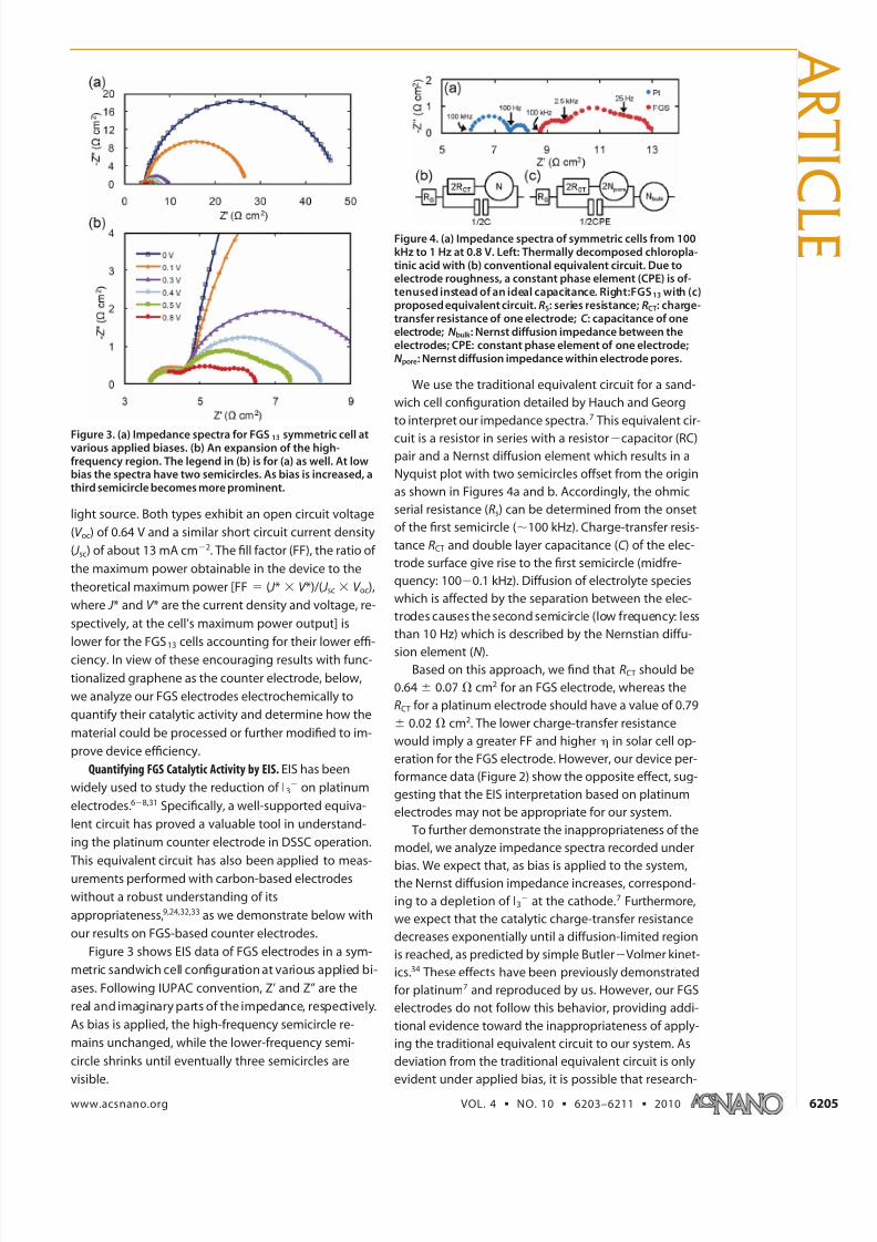
Figure 3 shows EIS data of FGS electrodes in a sym-
metric sandwich cell configuration at various applied bi-
ases. Following IUPAC convention, Z’ and Z” are the
real and imaginary parts of the impedance, respectively.
As bias is applied, the high-frequency semicircle re-
mains unchanged, while the lower-frequency semi-
circle shrinks until eventually three semicircles are
visible.
We use the traditional equivalent circuit for a sand-
wich cell configuration detailed by Hauch and Georg
to interpret our impedance spectra.7 This equivalent cir-
cuit is a resistor in series with a resistorϪcapacitor (RC)pair and a Nernst diffusion element which results in a
Nyquist plot with two semicircles offset from the origin
as shown in Figures 4a and b. Accordingly, the ohmic
serial resistance (Rs) can be determined from the onset
of the first semicircle (ϳ100 kHz). Charge-transfer resis-
tance RCT and double layer capacitance (C ) of the elec-
trode surface give rise to the first semicircle (midfre-
quency: 100Ϫ0.1 kHz). Diffusion of electrolyte species
which is affected by the separation between the elec-
trodes causes the second semicircle (low frequency: less
than 10 Hz) which is described by the Nernstian diffu-
sion element (N ).Based on this approach, we find that RCT should be
0.64 Ϯ 0.07 ⍀ cm2 for an FGS electrode, whereas the
RCT for a platinum electrode should have a value of 0.79
Ϯ 0.02 ⍀ cm2. The lower charge-transfer resistance
would imply a greater FF and higher in solar cell op-
eration for the FGS electrode. However, our device per-
formance data (Figure 2) show the opposite effect, sug-
gesting that the EIS interpretation based on platinum
electrodes may not be appropriate for our system.
To further demonstrate the inappropriateness of the
model, we analyze impedance spectra recorded under
bias. We expect that, as bias is applied to the system,the Nernst diffusion impedance increases, correspond-
ing to a depletion of I3Ϫ at the cathode.7 Furthermore,
we expect that the catalytic charge-transfer resistance
decreases exponentially until a diffusion-limited region
is reached, as predicted by simple ButlerϪVolmer kinet-
ics.34 These effects have been previously demonstrated
for platinum7 and reproduced by us. However, our FGS
electrodes do not follow this behavior, providing addi-
tional evidence toward the inappropriateness of apply-
ing the traditional equivalent circuit to our system. As
deviation from the traditional equivalent circuit is only
evident under applied bias, it is possible that research-
Figure 3. (a) Impedance spectra for FGS13 symmetric cell atvarious applied biases. (b) An expansion of the high-frequency region. The legend in (b) is for (a) as well. At lowbias the spectra have two semicircles. As bias is increased, athird semicircle becomes more prominent.
Figure 4. (a) Impedance spectra of symmetric cells from 100kHz to 1 Hz at 0.8 V. Left: Thermally decomposed chloropla-tinic acid with (b) conventional equivalent circuit. Due toelectrode roughness, a constant phase element (CPE) is of-tenused instead of an ideal capacitance. Right:FGS13 with (c)proposed equivalent circuit. RS: series resistance; RCT: charge-transfer resistance of one electrode; C : capacitance of oneelectrode; N bulk : Nernst diffusion impedance between theelectrodes; CPE: constant phase element of one electrode;N pore: Nernst diffusion impedance within electrode pores.
A R T I C
L E
www.acsnano.org VOL. 4 ▪ NO. 10 ▪ 6203–6211 ▪ 2010 6205
7/27/2019 Pu 10 4roy-Mayhew
http://slidepdf.com/reader/full/pu-10-4roy-mayhew 4/9
ers have misinterpreted their data in previous studies
and have underestimated the charge-transfer resis-
tance associated with their carbon electrodes. This mis-
interpretation could explain inconsistencies betweendevice performance and EIS charge-transfer resistance
data.
To more accurately explain our results, we propose
a model for porous FGS electrodes (and likely other po-
rous carbon electrodes) seen in Figure 4c in which we
attribute the high-frequency semicircle (100Ϫ2.5 kHz)
to a second Nernst diffusion impedance resulting from
diffusion through the electrode pores (N pore). The
middle semicircle (2500Ϫ25 Hz) represents the charge-
transfer resistance and the capacitance of the FGS/
electrolyte interface (RCT, CPE). As in the traditional ap-
proach, the low-frequency semicircle is determined bybulk Nernst diffusion (N bulk ), while the high-frequency
offset determines the serial resistance (Rs).
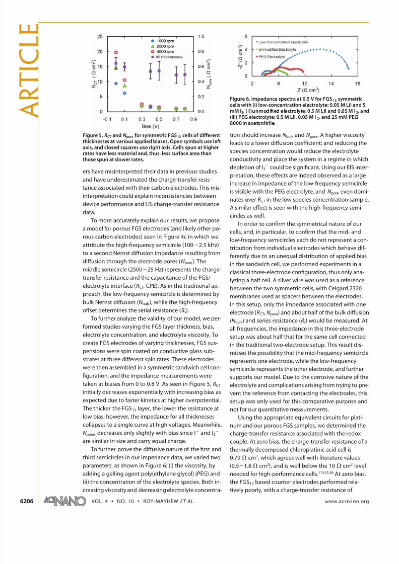
To further analyze the validity of our model, we per-
formed studies varying the FGS layer thickness, bias,
electrolyte concentration, and electrolyte viscosity. To
create FGS electrodes of varying thicknesses, FGS sus-
pensions were spin coated on conductive glass sub-
strates at three different spin rates. These electrodes
were then assembled in a symmetric sandwich cell con-
figuration, and the impedance measurements were
taken at biases from 0 to 0.8 V. As seen in Figure 5, RCT
initially decreases exponentially with increasing bias as
expected due to faster kinetics at higher overpotential.
The thicker the FGS13 layer, the lower the resistance at
low bias; however, the impedance for all thicknesses
collapses to a single curve at high voltages. Meanwhile,
N pores decreases only slightly with bias since IϪ and I3Ϫ
are similar in size and carry equal charge.
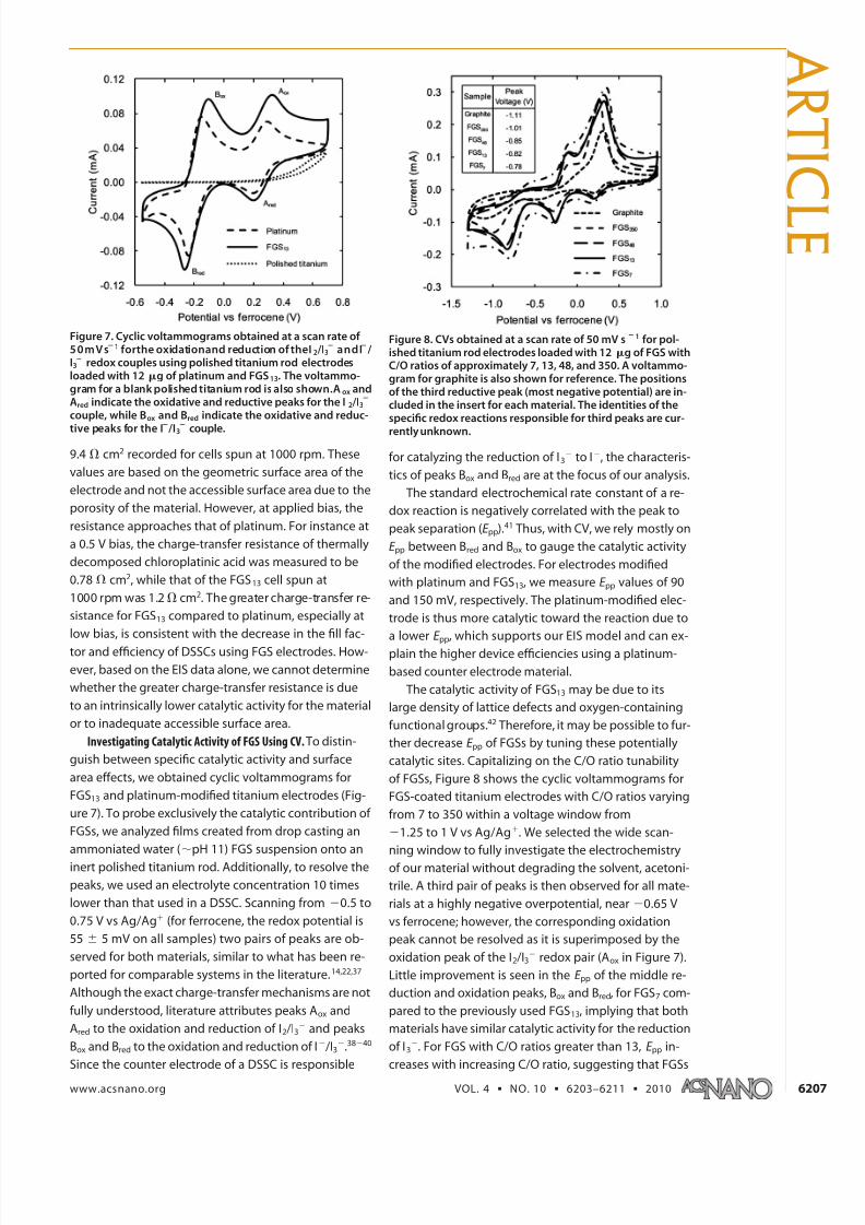
To further prove the diffusive nature of the first and
third semicircles in our impedance data, we varied two
parameters, as shown in Figure 6: (i) the viscosity, by
adding a gelling agent poly(ethylene glycol) (PEG) and
(ii) the concentration of the electrolyte species. Both in-
creasing viscosity and decreasing electrolyte concentra-
tion should increase N bulk and N pore. A higher viscosity
leads to a lower diffusion coefficient; and reducing the
species concentration would reduce the electrolyte
conductivity and place the system in a regime in which
depletion of I3Ϫ could be significant. Using our EIS inter-
pretation, these effects are indeed observed as a large
increase in impedance of the low-frequency semicircle
is visible with the PEG electrolyte, and N pore even domi-
nates over RCT in the low species concentration sample.
A similar effect is seen with the high-frequency semi-
circles as well.
In order to confirm the symmetrical nature of our
cells, and, in particular, to confirm that the mid- and
low-frequency semicircles each do not represent a con-
tribution from individual electrodes which behave dif-
ferently due to an unequal distribution of applied bias
in the sandwich cell, we performed experiments in a
classical three-electrode configuration, thus only ana-
lyzing a half cell. A silver wire was used as a reference
between the two symmetric cells, with Celgard 2320
membranes used as spacers between the electrodes.In this setup, only the impedance associated with one
electrode (RCT, N pore) and about half of the bulk diffusion
(N bulk ) and series resistance (Rs) would be measured. At
all frequencies, the impedance in this three-electrode
setup was about half that for the same cell connected
in the traditional two-electrode setup. This result dis-
misses the possibility that the mid-frequency semicircle
represents one electrode, while the low-frequency
semicircle represents the other electrode, and further
supports our model. Due to the corrosive nature of the
electrolyte and complications arising from trying to pre-
vent the reference from contacting the electrodes, thissetup was only used for this comparative purpose and
not for our quantitative measurements.
Using the appropriate equivalent circuits for plati-
num and our porous FGS samples, we determined the
charge-transfer resistance associated with the redox
couple. At zero bias, the charge-transfer resistance of a
thermally decomposed chloroplatinic acid cell is
0.79 ⍀ cm2, which agrees well with literature values
(0.5Ϫ1.8 ⍀ cm2), and is well below the 10 ⍀ cm2 level
needed for high-performance cells.7,9,35,36 At zero bias,
the FGS13 based counter electrodes performed rela-
tively poorly, with a charge-transfer resistance of
Figure 5. RCT and N pore for symmetric FGS13 cells of differentthicknesses at various applied biases. Open symbols use leftaxis, and closed squares use right axis. Cells spun at higherrates have less material and, thus, less surface area thanthose spun at slower rates.
Figure 6. Impedance spectra at 0.5 V for FGS13 symmetriccells with (i) low-concentration electrolyte: 0.05 M LiI and 5mM I2, (ii)unmodified electrolyte: 0.5 M LiI and 0.05 M I2, and(iii) PEG electrolyte: 0.5 M LiI, 0.05 M I2, and 25 mM PEG8000 in acetonitrile.
A R
T I C L E
VOL. 4 ▪ NO. 10 ▪ ROY-MAYHEW ET AL. www.acsnano.org6206
7/27/2019 Pu 10 4roy-Mayhew
http://slidepdf.com/reader/full/pu-10-4roy-mayhew 5/9
9.4 ⍀ cm2 recorded for cells spun at 1000 rpm. These
values are based on the geometric surface area of the
electrode and not the accessible surface area due to the
porosity of the material. However, at applied bias, the
resistance approaches that of platinum. For instance at
a 0.5 V bias, the charge-transfer resistance of thermally
decomposed chloroplatinic acid was measured to be
0.78 ⍀ cm2, while that of the FGS13 cell spun at
1000 rpm was 1.2⍀ cm2. The greater charge-transfer re-
sistance for FGS13 compared to platinum, especially at
low bias, is consistent with the decrease in the fill fac-
tor and efficiency of DSSCs using FGS electrodes. How-
ever, based on the EIS data alone, we cannot determine
whether the greater charge-transfer resistance is due
to an intrinsically lower catalytic activity for the material
or to inadequate accessible surface area.
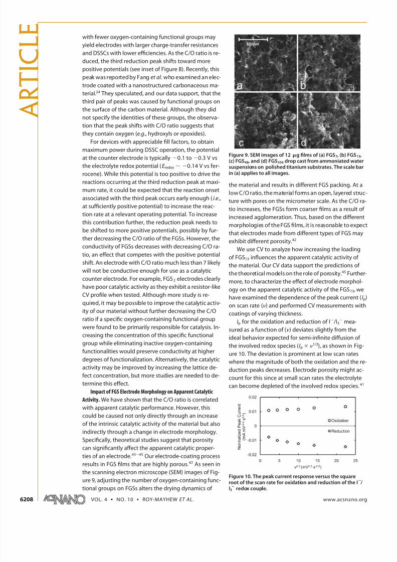
Investigating Catalytic Activity of FGS Using CV. To distin-
guish between specific catalytic activity and surface
area effects, we obtained cyclic voltammograms for
FGS13 and platinum-modified titanium electrodes (Fig-
ure 7). To probe exclusively the catalytic contribution of
FGSs, we analyzed films created from drop casting an
ammoniated water (ϳpH 11) FGS suspension onto an
inert polished titanium rod. Additionally, to resolve the
peaks, we used an electrolyte concentration 10 times
lower than that used in a DSSC. Scanning from Ϫ0.5 to
0.75 V vs Ag/Agϩ (for ferrocene, the redox potential is
55 Ϯ 5 mV on all samples) two pairs of peaks are ob-
served for both materials, similar to what has been re-
ported for comparable systems in the literature.14,22,37
Although the exact charge-transfer mechanisms are not
fully understood, literature attributes peaks Aox and
Ared to the oxidation and reduction of I2 /I3Ϫ and peaks
Box and Bred to the oxidation and reduction of IϪ /I3Ϫ.38Ϫ40
Since the counter electrode of a DSSC is responsible
for catalyzing the reduction of I3Ϫ to IϪ, the characteris-
tics of peaks Box and Bred are at the focus of our analysis.
The standard electrochemical rate constant of a re-
dox reaction is negatively correlated with the peak to
peak separation (E pp).41 Thus, with CV, we rely mostly on
E pp between Bred and Box to gauge the catalytic activity
of the modified electrodes. For electrodes modified
with platinum and FGS13, we measure E pp values of 90
and 150 mV, respectively. The platinum-modified elec-
trode is thus more catalytic toward the reaction due to
a lower E pp, which supports our EIS model and can ex-
plain the higher device efficiencies using a platinum-
based counter electrode material.
The catalytic activity of FGS13 may be due to its
large density of lattice defects and oxygen-containing
functional groups.42 Therefore, it may be possible to fur-
ther decrease E pp of FGSs by tuning these potentially
catalytic sites. Capitalizing on the C/O ratio tunability
of FGSs, Figure 8 shows the cyclic voltammograms for
FGS-coated titanium electrodes with C/O ratios varying
from 7 to 350 within a voltage window from
Ϫ1.25 to 1 V vs Ag/Agϩ. We selected the wide scan-
ning window to fully investigate the electrochemistry
of our material without degrading the solvent, acetoni-
trile. A third pair of peaks is then observed for all mate-
rials at a highly negative overpotential, near Ϫ0.65 V
vs ferrocene; however, the corresponding oxidation
peak cannot be resolved as it is superimposed by the
oxidation peak of the I2 /I3Ϫ redox pair (Aox in Figure 7).
Little improvement is seen in the E pp of the middle re-
duction and oxidation peaks, Box and Bred, for FGS7 com-
pared to the previously used FGS13, implying that both
materials have similar catalytic activity for the reduction
of I3Ϫ. For FGS with C/O ratios greater than 13, E pp in-
creases with increasing C/O ratio, suggesting that FGSs
Figure 7. Cyclic voltammograms obtained at a scan rate of 5 0 m V s 1 forthe oxidationand reduction of theI2/I3 andI /I3 redox couples using polished titanium rod electrodesloaded with 12 g of platinum and FGS13. The voltammo-gram for a blank polished titanium rod is also shown.Aox andAred indicate the oxidative and reductive peaks for the I 2/I3
couple, while Box and Bred indicate the oxidative and reduc-
tive peaks for the I /I3 couple.
Figure 8. CVs obtained at a scan rate of 50 mV s 1 for pol-ished titanium rod electrodes loaded with 12g of FGS withC/O ratios of approximately 7, 13, 48, and 350. A voltammo-gram for graphite is also shown for reference. The positionsof the third reductive peak (most negative potential) are in-cluded in the insert for each material. The identities of thespecific redox reactions responsible for third peaks are cur-
rently unknown.
A R T I C
L E
www.acsnano.org VOL. 4 ▪ NO. 10 ▪ 6203–6211 ▪ 2010 6207
7/27/2019 Pu 10 4roy-Mayhew
http://slidepdf.com/reader/full/pu-10-4roy-mayhew 6/9
with fewer oxygen-containing functional groups may
yield electrodes with larger charge-transfer resistances
and DSSCs with lower efficiencies. As the C/O ratio is re-
duced, the third reduction peak shifts toward more
positive potentials (see inset of Figure 8). Recently, this
peak was reported by Fang et al . who examined an elec-
trode coated with a nanostructured carbonaceous ma-
terial.24 They speculated, and our data support, that the
third pair of peaks was caused by functional groups on
the surface of the carbon material. Although they did
not specify the identities of these groups, the observa-
tion that the peak shifts with C/O ratio suggests that
they contain oxygen (e.g., hydroxyls or epoxides).
For devices with appreciable fill factors, to obtain
maximum power during DSSC operation, the potential
at the counter electrode is typically Ϫ0.1 to Ϫ0.3 V vs
the electrolyte redox potential (E redox ϳ Ϫ0.14 V vs fer-
rocene). While this potential is too positive to drive the
reactions occurring at the third reduction peak at maxi-
mum rate, it could be expected that the reaction onset
associated with the third peak occurs early enough ( i .e.,at sufficiently positive potential) to increase the reac-
tion rate at a relevant operating potential. To increase
this contribution further, the reduction peak needs to
be shifted to more positive potentials, possibly by fur-
ther decreasing the C/O ratio of the FGSs. However, the
conductivity of FGSs decreases with decreasing C/O ra-
tio, an effect that competes with the positive potential
shift. An electrode with C/O ratio much less than 7 likely
will not be conductive enough for use as a catalytic
counter electrode. For example, FGS2 electrodes clearly
have poor catalytic activity as they exhibit a resistor-like
CV profile when tested. Although more study is re-quired, it may be possible to improve the catalytic activ-
ity of our material without further decreasing the C/O
ratio if a specific oxygen-containing functional group
were found to be primarily responsible for catalysis. In-
creasing the concentration of this specific functional
group while eliminating inactive oxygen-containing
functionalities would preserve conductivity at higher
degrees of functionalization. Alternatively, the catalytic
activity may be improved by increasing the lattice de-
fect concentration, but more studies are needed to de-
termine this effect.
Impact of FGS Electrode Morphology on Apparent CatalyticActivity. We have shown that the C/O ratio is correlated
with apparent catalytic performance. However, this
could be caused not only directly through an increase
of the intrinsic catalytic activity of the material but also
indirectly through a change in electrode morphology.
Specifically, theoretical studies suggest that porosity
can significantly affect the apparent catalytic proper-
ties of an electrode.43Ϫ45 Our electrode-coating process
results in FGS films that are highly porous.42 As seen in
the scanning electron microscope (SEM) images of Fig-
ure 9, adjusting the number of oxygen-containing func-
tional groups on FGSs alters the drying dynamics of
the material and results in different FGS packing. At a
low C/O ratio, the material forms an open, layered struc-
ture with pores on the micrometer scale. As the C/O ra-
tio increases, the FGSs form coarser films as a result of
increased agglomeration. Thus, based on the different
morphologies of the FGS films, it is reasonable to expect
that electrodes made from different types of FGS may
exhibit different porosity.42
We use CV to analyze how increasing the loading
of FGS13 influences the apparent catalytic activity of
the material. Our CV data support the predictions of
the theoretical models on the role of porosity.45 Further-
more, to characterize the effect of electrode morphol-
ogy on the apparent catalytic activity of the FGS13, we
have examined the dependence of the peak current (I p)
on scan rate () and performed CV measurements with
coatings of varying thickness.
I p for the oxidation and reduction of IϪ /I3Ϫ mea-
sured as a function of () deviates slightly from the
ideal behavior expected for semi-infinite diffusion of
the involved redox species (I p ϰ 1/2), as shown in Fig-
ure 10. The deviation is prominent at low scan rates
where the magnitude of both the oxidation and the re-
duction peaks decreases. Electrode porosity might ac-
count for this since at small scan rates the electrolyte
can become depleted of the involved redox species.41
Figure 9. SEM images of 12 g films of (a) FGS7, (b) FGS13,(c) FGS48, and (d) FGS350 drop cast from ammoniated watersuspensions on polished titanium substrates. The scale barin (a) applies to all images.
Figure 10. The peak current response versus the squareroot of the scan rate for oxidation and reduction of the I /I3 redox couple.
A R
T I C L E
VOL. 4 ▪ NO. 10 ▪ ROY-MAYHEW ET AL. www.acsnano.org6208
7/27/2019 Pu 10 4roy-Mayhew
http://slidepdf.com/reader/full/pu-10-4roy-mayhew 7/9
The effect is more pronounced for the reduction peak
since the concentration of I3Ϫ is considerably lower thanthe concentration of IϪ.
An additional indication for an impact of electrode
morphology is the dependence of E pp and I p on the
thickness of the electrode coating (Figure 11). The geo-
metric areas of all tested electrodes are identical. There-
fore, higher loadings correspond to thicker films. As
seen in the insert of Figure 11, E pp of the IϪ /I3Ϫ redox re-
action is much larger for the electrode with 2 g FGS13
than for those with higher loadings. The reduction po-
tential (peak Bred) experiences a significant positive shift
as the FGS13 loading increases. At the same time, the
peak current (and also the capacitive background cur-rent) increases indicating a higher accessible surface
area. Since we do not know the exact relation between
electrode loading and accessible surface area, we can-
not analyze the data quantitatively. However, the ob-
served behavior is reminiscent of cyclic voltammo-
grams simulated for electrodes of varying porosity.45
We then conclude that the observed differences in the
apparent catalytic activity of the tested electrodes are
probably in part affected by differences in electrode
morphology. This is of particular importance when
comparing different electrode materials (see Figure 8)
as different materials may result in different electrodeporosity and, thus, different apparent catalytic activities.
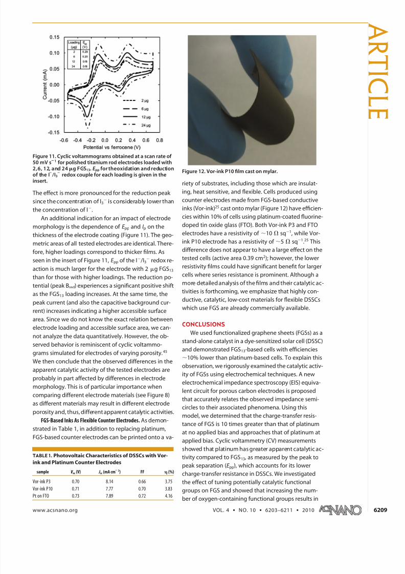
FGS-Based Inks As Flexible Counter Electrodes. As demon-
strated in Table 1, in addition to replacing platinum,
FGS-based counter electrodes can be printed onto a va-
riety of substrates, including those which are insulat-
ing, heat sensitive, and flexible. Cells produced using
counter electrodes made from FGS-based conductiveinks (Vor-ink)25 cast onto mylar (Figure 12) have efficien-
cies within 10% of cells using platinum-coated fluorine-
doped tin oxide glass (FTO). Both Vor-ink P3 and FTO
electrodes have a resistivity of ϳ10 ⍀ sqϪ1, while Vor-
ink P10 electrode has a resistivity of ϳ5 ⍀ sqϪ1.25 This
difference does not appear to have a large effect on the
tested cells (active area 0.39 cm2); however, the lower
resistivity films could have significant benefit for larger
cells where series resistance is prominent. Although a
more detailed analysis of the films and their catalytic ac-
tivities is forthcoming, we emphasize that highly con-
ductive, catalytic, low-cost materials for flexible DSSCswhich use FGS are already commercially available.
CONCLUSIONS
We used functionalized graphene sheets (FGSs) as a
stand-alone catalyst in a dye-sensitized solar cell (DSSC)
and demonstrated FGS13-based cells with efficiencies
ϳ10% lower than platinum-based cells. To explain this
observation, we rigorously examined the catalytic activ-
ity of FGSs using electrochemical techniques. A new
electrochemical impedance spectroscopy (EIS) equiva-
lent circuit for porous carbon electrodes is proposed
that accurately relates the observed impedance semi-circles to their associated phenomena. Using this
model, we determined that the charge-transfer resis-
tance of FGS is 10 times greater than that of platinum
at no applied bias and approaches that of platinum at
applied bias. Cyclic voltammetry (CV) measurements
showed that platinum has greater apparent catalytic ac-
tivity compared to FGS13, as measured by the peak to
peak separation (E pp), which accounts for its lower
charge-transfer resistance in DSSCs. We investigated
the effect of tuning potentially catalytic functional
groups on FGS and showed that increasing the num-
ber of oxygen-containing functional groups results in
Figure 11. Cyclic voltammograms obtained at a scan rate of 50 mV s 1 for polished titanium rod electrodes loaded with2,6, 12, and 24g FGS13. E pp for theoxidation and reductionof the I /I3 redox couple for each loading is given in theinsert.
TABLE 1. Photovoltaic Characteristics of DSSCs with Vor-
ink and Platinum Counter Electrodes
sample V oc (V) J sc (mA cm 2) FF (%)
Vor-ink P3 0.70 8.14 0.66 3.75
Vor-ink P10 0.71 7.77 0.70 3.83
Pt on FTO 0.73 7.89 0.72 4.16
Figure 12. Vor-ink P10 film cast on mylar.
A R T I C
L E
www.acsnano.org VOL. 4 ▪ NO. 10 ▪ 6203–6211 ▪ 2010 6209
7/27/2019 Pu 10 4roy-Mayhew
http://slidepdf.com/reader/full/pu-10-4roy-mayhew 8/9
an increase of the material’s apparent catalytic activity.
We also recognized how fabricating a more porous FGS
electrode could improve the apparent catalytic activ-
ity. Finally, we demonstrated that FGS-based inks cast
on a nonconductive plastic substrate can be effectively
used as a counter electrode, eliminating the need for a
conductive substrate. Cells employing this versatile
FGS-ink flexible counter electrode performed ϳ10%
less efficiently than cells using platinum on a rigid
fluorine-doped tin oxide glass (FTO) electrode. Tailor-
ing the functionalization or morphology of the FGS
electrodes could decrease their charge-transfer resis-
tance and facilitate the low-cost production of catalytic,
flexible, and conductive counter electrodes for DSSCs.
EXPERIMENTAL METHODS
Preparation of Counter Electrodes. For electrodes used in EIS andDSSCs, FGS counter electrodes were prepared on FTO (TEC8,
Hartford Glass). FGS-surfactant (poly(ethylene oxide)-poly(propylene oxide)-poly(ethylene oxide) triblock copolymer,
F127, Pluronic) suspension (1.66 wt % FGS, 1.66 wt % F127 in wa-ter) was mixed in a poly(ethylene oxide) (PEO, Mv 600 000) solu-
tion (0.6 g in 10 mL water, 10 mL ethanol) in a 1:4 FGS:PEOweight ratio and stirred overnight. The resulting suspension
was spin coated onto clean FTO substrates at given speeds for4 min. The resulting film was dried at room temperature, and
then the surfactants were thermally decomposed in an ashingfurnace at 350 °C in air for 2 h. Thermally treated chloroplatinic
acid electrodes were prepared as described previously.8 Briefly, 2L of 5 mM chloroplatinic acid in isopropanol was drop cast on
an FTO electrode with a 0.39 cm2 mask. The sample was thenheated to 380 °C for 20 min before use. FGS-based Vor-ink filmswere cast on mylar by Vorbeck Materials25 and used as received.
Electrodes for CV were prepared by drop casting an ϳpH 11aqueous suspension of FGS x (Vor-x BK86 from Vorbeck Materi-
als)25 on the tips of titanium rods (grade 2, diameter ϭ 1/8 inch,McMaster). Thermally treated chloroplatinic acid electrodes were
also prepared using titanium rods. Combustion-based chemicalanalysis (Atlantic Microlab Inc., GA) was used to determine the
C/O ratio of the FGS samples. Titanium was selected as the elec-trode bulk material due to its high electrical conductivity, highcorrosionresistance in the IϪ /I2 electrolyte solution, and low cata-
lytic activity for the redox reaction of interest.Preparation of DSSCs. DSSCs were constructed as described pre-
viously in the literature.3
In brief, 2 g of P25 titania nanoparti-cles (Evanonik) were suspended with 66 L of acetylacetone and
3.333 mL deionized water. Titania films, four layers thick, werecast on TiCl4 treated FTO glass using a scotch tape mask and aglass rod via the doctor blade technique. These films were then
heated to 485 °C for 30 min in air before being placed in a 0.2 M TiCl4 solution for 12 h and heated to 450 °C for 30 min. The re-
sulting electrode was immersed in a 0.3 mM N3 dye/ethanol(Acros) solutionfor 20 h to form thesensitizedphotoanode.Plati-
num and FGS counter electrodes were formed as describedabove. A 25 m Surlyn film (Solaronix) was used to separate
the photoanode and the counter electrode and to seal the cellafter electrolyte (Iodolyte AN-50 from Solaronix) was added. Forthe Vor-ink data series (Table 1), TiCl4 treatments were not per-
formed. Also, due to the flexible nature of the Vor-ink films, toprevent short circuiting of the cells, the electrodes were sepa-
rated by 100 m thick laboratory tape (Fisher) and clamped to-gether using binder clips. Cells were tested immediately after
fabrication.All chemicals were electrochemical grade from Sigma Ald-
rich and used as received, unless otherwise noted.
Measurements. CV and EIS were performed using a Biologic SP-150 potentiostat. The CV study was performed in a single com-
partment, three-electrode setup using an acetonitrile solutioncontaining 0.1 M LiClO4, 5 mM LiI, and 0.5 mM I2. A Ag/Agϩ ref-
erence electrode (0.01 M AgNO3 in acetonitrile) was used, andthe cells were normalized to an external ferrocene reference. EISwas performed using a sandwich cell configuration with sym-
metric films in an acetonitrile electrolyte containing 0.5 M LiI and0.05 M I2 unless otherwise noted. A 25 m Surlyn film was used
to separate the films and to seal the cells. EIS measurementswere taken from 0 to 0.8 V, the magnitude of the alternating sig-
nal was 10 mV, and the frequency range was 1 Hz to 400 kHz.
ZFit (Biologic), with the appropriate equivalent circuit, was used
to analyze the impendence spectra. CurrentϪvoltage character-
istics of DSSCs were taken under AM1.5G light, simulated at
100mW/cm2 with a 16S solar simulator (SolarLight) using the po-
tentiostat to apply various loads. Data values presented are the
average of 2Ϫ6 identically prepared samples, while figures are
representative of individual runs unless otherwise noted. The
morphology of the electrodes was investigated by SEM (model
5130MM, Tescan) under 20 kV accelerating voltage.
Acknowledgment. This work was supported by the Pacific
Northwest National Laboratory (operated for the United States
Department of Energy by Battelle) through Battelle grant no.
66354 and the Army Research Office (ARO)/Multidisciplinary Re-search Initiative (MURI) under grant no. W911NF-09-1-0476.
J.R-M. received stipend support through the National Science
Foundation Graduate Research Fellowship. The authors thank
A. Bocarsly for his helpful discussions on the electrochemical as-
pects of this project and J. Lettow of Vorbeck Materials Corpora-
tion for supplying Vor-x and Vor-ink.
REFERENCES AND NOTES
1. O’Regan, B.; Gratzel, M. A Low-Cost, High-Efficiency Solar
Cell Based on Dye-Sensitized Colloidal TiO2 Films. Nature
1991, 353, 737–740.
2. Gratzel, M. Solar Energy Conversion by Dye-Sensitized
Photovoltaic Cells. Inorg. Chem. 2005, 44, 6841–6851.
3. Nazeeruddin, M. K.; Kay, A.; Rodicio, I.; Humphry-Baker, R.;
Muller, E.; Liska, P.; Vlachopoulos, N.; Gratzel, M.Conversion of Light to Electricity by Cis-X2bis(2,2=-
Bipyridyl-4,4=-Dicarboxylate)Ruthenium(II) Charge-Transfer
Sensitizers (X ϭ ClϪ, BrϪ, IϪ, CNϪ, and SCNϪ) on
Nanocrystalline Titanium Dioxide Electrodes. J. Am. Chem.
Soc. 1993, 115, 6382–6390.
4. Chiba, Y.; Islam, A.; Watanabe, Y.; Komiya, R.; Koide, N.;
Han, L. Dye-Sensitized Solar Cells with Conversion
Efficiency of 11.1%. Jpn. J. Appl. Phys. 2006, 45, L638–L640.
5. Gao, F.; Wang, Y.; Zhang, J.; Shi, D.; Wang, M.; Humphry-
Baker, R.; Wang, P.; Zakeeruddin, S. M.; Gratzel, M. A New
Heteroleptic Ruthenium Sensitizer Enhances the
Absorptivity of Mesoporous Titania Film for a High
Efficiency Dye-Sensitized Solar Cell. Chem. Commun. 2008,
2635–2637.
6. Bonnemann, H.; Khelashvili, G.; Behrens, S.; Hinsch, A.;
Skupien, K.; Dinjus, E. Role of the Platinum Nanoclusters inthe Iodide/Triiodide Redox System of Dye Solar Cells. J.
Cluster Sci. 2007, 18, 141–155.
7. Hauch, A.; Georg, A. Diffusion in the Electrolyte and
Charge-Transfer Reaction at the Platinum Electrode in
Dye-Sensitized Solar Cells. Electrochim. Acta 2001, 46,
3457–3466.
8. Papageorgiou, N.; Maier, W. F.; Gratzel, M. An
Iodine/Triiodide Reduction Electrocatalyst for Aqueous
and Organic Media. J. Electrochem. Soc. 1997, 144,
876–884.
9. Lee, W. J.; Ramasamy, E.; Lee, D. Y.; Song, J. S. Performance
Variation of Carbon Counter Electrode Based Dye-
Sensitized Solar Cell. Sol. Energy Mater. Sol. Cells 2008, 92,
814–818.
10. Lindstrom, H.; Holmberg, A.; Magnusson, E.; Lindquist, S.-
A R
T I C L E
VOL. 4 ▪ NO. 10 ▪ ROY-MAYHEW ET AL. www.acsnano.org6210
7/27/2019 Pu 10 4roy-Mayhew
http://slidepdf.com/reader/full/pu-10-4roy-mayhew 9/9
E.; Malmqvist, L.; Hagfeldt, A. A New Method for
Manufacturing Nanostructured Electrodes on PlasticSubstrates. Nano Lett. 2001, 1, 97–100.
11. Kay, A.; Gratzel, M. Low Cost Photovoltaic Modules Based
on Dye Sensitized Nanocrystalline Titanium Dioxide and
Carbon Powder. Sol. Energy Mater. Sol. Cells 1996, 44,
99–117.12. Zhu, H.; Wei, J.; Wang, K.; Wu, D. Applications of Carbon
Materials in Photovoltaic Solar Cells. Sol. Energy Mater. Sol.
Cells 2009, 93, 1461–1470.
13. Chen, J.; Li, K.; Luo, Y.; Guo, X.; Li, D.; Deng, M.; Huang, S.;Meng, Q. A Flexible Carbon Counter Electrode for Dye-
Sensitized Solar Cells. Carbon 2009, 47 , 2704–2708.
14. Huang, Z.; Liu, X.; Li, K.; Li, D.; Luo, Y.; Li, H.; Song, W.; Chen,
L.; Meng, Q. Application of Carbon Materials as Counter
Electrodes of Dye-Sensitized Solar Cells. Electrochem.Commun. 2007, 9, 596–598.
15. Easwaramoorthi, R.; Won Jae, L.; Dong Yoon, L.; Jae Sung,
S. Nanocarbon Counterelectrode for Dye Sensitized Solar
Cells. Appl. Phys. Lett. 2007, 90, 173103.16. Trancik, J. E.; Barton, S. C.; Hone, J. Transparent and
Catalytic Carbon Nanotube Films. Nano Lett. 2008, 8, 982–
987.
17. Suzuki, K.; Yamaguchi, M.; Kumagai, M.; Yanagida, S.
Application of Carbon Nanotubes to Counter Electrodes of Dye-Sensitized Solar Cells. Chem. Lett. 2003, 32, 28–29.
18. Nam, J. G.; Park, Y. J.; Kim, B. S.; Lee, J. S. Enhancement of the Efficiency of Dye-Sensitized Solar Cell by Utilizing
Carbon Nanotube Counter Electrode. Scr. Mater. 2010, 62,
148–150.19. Murakami, T. N.; Gratzel, M. Counter Electrodes for Dsc:
Application of Functional Materials as Catalysts. Inorg.
Chim. Acta 2008, 361, 572–580.
20. Denaro, T.; Baglio, V.; Girolamo, M.; Antonucci, V.; Arico,A. S.; Matteucci, F.; Ornelas, R. Investigation of Low Cost
Carbonaceous Materials for Application as Counter
Electrode in Dye-Sensitized Solar Cells. J. Appl. Electrochem.
2009, 39, 2173–2179.
21. Xu, Y.; Bai, H.; Lu, G.; Li, C.; Shi, G. Flexible Graphene FilmsVia the Filtration of Water-Soluble Noncovalent
Functionalized Graphene Sheets. J. Am. Chem. Soc. 2008,
130, 5856–5857.
22. Hong, W. J.; Xu, Y. X.; Lu, G. W.; Li, C.; Shi, G. Q. TransparentGraphene/Pedot-Pss Composite Films as CounterElectrodes of Dye-Sensitized Solar Cells. Electrochem.
Commun. 2008, 10, 1555–1558.
23. Choi, H.; Kim, H.; Hwang, S.; Choi, W.; Jeon, M., Dye-
Sensitized Solar Cells Using Graphene-Based Carbon NanoComposite as Counter Electrode. Sol. Energy Mater. Sol.
Cells; DOI ϭ 10.1016/j.solmat.2010.04.044.
24. Fang, B.; Fan, S.-Q.; Kim, J. H.; Kim, M.-S.; Kim, M.;
Chaudhari, N. K.; Ko, J.; Yu, J.-S. Incorporating Hierarchical
Nanostructured Carbon Counter Electrode into Metal-FreeOrganic Dye-Sensitized Solar Cell. Langmuir 2010, 26,
11238–11243.
25. Manufactured by Vorbeck Materials Corporation, Jessup,
MD.
26. McAllister, M. J.; Li, J.-L.; Adamson, D. H.; Schniepp, H. C.;Abdala, A. A.; Liu, J.; Herrera-Alonso, M.; Milius, D. L.; Car,
R.; Prud’homme, R. K.; Aksay, I. A. Single Sheet
Functionalized Graphene by Oxidation and Thermal
Expansion of Graphite. Chem. Mater. 2007, 19, 4396–4404.27. Schniepp, H. C.; Li, J.-L.; McAllister, M. J.; Sai, H.; Herrera-
Alonso, M.; Adamson, D. H.; Prud’homme, R. K.; Car, R.;
Saville, D. A.; Aksay, I. A. Functionalized Single GrapheneSheets Derived from Splitting Graphite Oxide. J. Phys.
Chem. B 2006, 110, 8535–8539.
28. Kudin, K. N.; Ozbas, B.; Schniepp, H. C.; Prud’homme, R. K.;
Aksay, I. A.; Car, R. Raman Spectra of Graphite Oxide andFunctionalized Graphene Sheets. Nano Lett. 2007, 8,
36–41.
29. Schniepp, H. C.; Kudin, K. N.; Li, J.-L.; Prud’homme, R. K.;Car, R.; Saville, D. A.; Aksay, I. A. Bending Properties of
Single Functionalized Graphene Sheets Probed by Atomic
Force Microscopy. ACS Nano 2008, 2, 2577–2584.
30. Sato, K.; Saito, R.; Oyama, Y.; Jiang, J.; Cancado, L. G.;Pimenta, M. A.; Jorio, A.; Samsonidze, G. G.; Dresselhaus,G.; Dresselhaus, M. S. D-Band Raman Intensity of GraphiticMaterials as a Function of Laser Energy and Crystallite Size.Chem. Phys. Lett. 2006, 427 , 117–121.
31. Fang, X.; Ma, T.; Guan, G.; Akiyama, M.; Kida, T.; Abe, E.Effect of the Thickness of the Pt Film Coated on a CounterElectrode on the Performance of a Dye-Sensitized SolarCell. J. Electroanal. Chem. 2004, 570, 257–263.
32. Wang, G.; Xing, W.; Zhuo, S. Application of Mesoporous
Carbon to Counter Electrode for Dye-Sensitized Solar Cells. J. Power Sources 2009, 194, 568–573.
33. Peng, S.; Cheng, F.; Shi, J.; Liang, J.; Tao, Z.; Chen, J. High-Surface-Area Microporous Carbon as the EfficientPhotocathode of Dye-Sensitized Solar Cells. Solid State Sci.2009, 11, 2051–2055.
34. H Hamann, C. H.; Hamnett, A.; Vielstich, W.Electrochemistry ; Wiley-VCH: New York, 1998.
35. Wang, D.; Choi, D.; Li, J.; Yang, Z.; Nie, Z.; Kou, R.; Hu, D.;Wang, C.; Saraf, L. V.; Zhang, J.; et al. Self-Assembled TiO2-Graphene Hybrid Nanostructures for Enhanced Li-IonInsertion ACS Nano; 2009, 3, 907Ϫ914.
36. Murakami, T. N.; Ito, S.; Wang, Q.; Nazeeruddin, M. K.;Bessho, T.; Cesar, I.; Liska, P.; Humphry-Baker, R.; Comte, P.;Pechy, P.; Gratzel, M. Highly Efficient Dye-Sensitized SolarCells Based on Carbon Black Counter Electrodes. J.Electrochem. Soc. 2006, 153, A2255–A2261.
37. Li, P.; Wu, J.; Lin, J.; Huang, M.; Huang, Y.; Li, Q. High-Performance and Low Platinum Loading Pt/Carbon Black Counter Electrode for Dye-Sensitized Solar Cells. Sol.Energy 2009, 83, 845–849.
38. Popov, A. I.; Geske, D. H. Studies of the Chemistry of Halogen and of Polyhalides. Xiii. Voltammetry of IodineSpecies in Acetonitrile. J. Am. Chem. Soc. 1958, 80.
39. Baucke, F. G. K.; Bertram, R.; Cruse, K. The Iodide-IodineSystem in Acetonitrile: Evaluation of Standard Thermodynamic Data on the Association IϪϩI2 ¡ I3
Ϫ
from Potentiometric Measurements at 25 and 50°C. J.Electroanal. Chem. 1971, 32, 247–256.
40. Boschloo, G.; Hagfeldt, A. Characteristics of theIodide/Triiodide Redox Mediator in Dye-Sensitized SolarCells. Acc. Chem. Res. 2009, 42, 1819–1826.
41. Compton, R. G.; Banks, C. E. Understanding Voltammetry ;
World Scientific: Singapore, 2007.42. Punckt, C.; Pope, M. A.; Liu, J.; Lin, Y.; Aksay, I. A.,
Electrochemical Performance of Graphene as Effected byElectrode Porosity and Graphene Functionalization.Electroanalysis 2010, 26; in press.
43. Austin, L. G. Porous Electrodes. In Comprehensive Treatiseof Electrochemistry ; Yaeger, E., Bockris, J. O. M., Conway,B. E., Sarangapani, S., Eds.; Plenum Press: New York, 1964;Vol. 6.
44. Austin, L. G. Tafel Slopes for Flooded Diffusion Electrodes.Trans. Faraday Soc. 1964, 60, 1319–1324.
45. Menshykau, D.; Compton, R. G. The Influence of ElectrodePorosity on Diffusional Cyclic Voltammetry. Electroanalysis2008, 20, 2387–2394.
A R T I C
L E
www.acsnano.org VOL. 4 ▪ NO. 10 ▪ 6203–6211 ▪ 2010 6211