Embed Size (px)
Citation preview
Quartz® by StoneLValve monitor series QX/QN/QG
Installation, Maintenance andOperating instructions
7 QZ 70 en • 03/2017
StoneL publication 105406revA
7 QZ 70 en2 | Quartz
StoneL publication 105406revA
Read these instructions first!These instructions provide information about safe handling and operation of the limit switch. If you require additional assistance, please contact the manufacturer or manufacturer’s representative. Addresses and phone numbers are printed on the back cover.Save these instructions.Subject to change without notice.All trademarks are property of their respective owners.
Table of contents1 General 4
1.1 Introduction 41.2 Title plate markings 41.3 CE markings 41.4 Recycling and disposal 41.5 Safety precautions 41.6 Assembly drawing 51.7 Specifications for all models 51.8 Dimensions 6
2 Assembly and mounting 72.1 Typical Quartz with extended visual indicator assembly figure 72.2 Instructions for mounting with extended visual indicator 72.3 Typical Quartz with short visual indicator assembly figure 82.4 Instructions for mounting with short visual indicator 8
3 Maintenance, repair and installation 93.1 Maintenance and repair 93.2 Installation 9
4 Function specific details 104.1 Inductive proximity sensors 10
4.1.1 Dual module SST sensors (33) 104.1.2 Dual module SST sensors (35) 114.1.3 SST solid state proximity senors (X) 124.1.4 P+F 3-wire solid state proximity sensors (E, F) 14
4.2 Intrinsically safe inductive proximity switches 164.2.1 Dual module NAMUR sensors (44) 164.2.2 Dual module NAMUR sensors (45) 174.2.3 P+F NAMUR sensors NJ2-12GK-SN (A) 184.2.4 P+F NAMUR sensors NJ2-V3-N (N) 19
4.3 Reed type proximity switches 204.3.1 SPST Maxx-Guard proximity sensors (L, P) 204.3.2 SPDT Maxx-Guard proximity sensors (G, H, S) 214.3.3 Intrinsically safe models with SPST Maxx-Guard proximity sensors (J) 224.3.4 Intrinsically safe models with SPDT Maxx-Guard proximity sensors (M) 23
4.4 Mechanical micro switches 244.4.1 Silver contacts (V) and gold contacts (W) 244.4.2 DPDT switches (14) 26
4.5 Valve communication terminals (VCT) 284.5.1 VCT with DeviceNet™ communication (92) 284.5.2 VCT with Foundation Fieldbus communication (93) 304.5.3 VCT with AS- Interface communication (96) 324.5.4 VCT with AS-Interface communication and extended addressing (97) 33
4.6 Position transmitters and potentiometers 344.6.1 4 to 20 mA position transmitters with and without switches (Type 5_, 7_) 344.6.2 Potentiometer with and without switches (Type B_, C_) 37
4.7 Expeditors 404.7.1 Operation sequences 404.7.2 With mechanical switches (8V, 8W) 414.7.3 With Maxx-Guard proximity sensors (8Y) 424.7.4 With DeviceNet™ communication (82) 434.7.5 With Foundation Fieldbus communication (83) 444.7.6 With AS-Interface communication (86) 45
StoneL publication 105406revA
7 QZ 70 en Quartz | 3
Table of contents continued
5 Model/Type code 465.1 QGabcdef 465.2 QNabcdef 465.3 QXabcdef 46
6 Regulatory, specific conditions of use, and product marking 47
7 Appendix 497.1 Controlled installation drawings 49

7 QZ 70 en4 | Quartz
StoneL publication 105406revA
1 General1.1 IntroductionThis manual incorporates the Installation, Maintenance and Operation (IMO) instructions for the Quartz series valve monitors. The Quartz is designed to provide position feedback indication of on/off automated valves.
NoteThe selection and use of the Quartz in a specific application requires close consideration of detailed aspects. Due to the nature of the product, this manual cannot cover all the likely situations that may occur when installing, using, or servicing the Quartz. If you are uncertain about the use of this device, or its suitability for your intended use, please contact StoneL for assistance.
1.2 Title plate markingsThe Quartz has an identification plate attached to the cover.1. Identification plate markings2. Model3. Serial number4. Date5. Sensor rating6. Transmitter rating (if installed)7. Protection class information*8. Note9. Warning10. Approval markings*11. Logo
Note* See page 47 for specific product markings.
1.3 CE markingsThe Quartz by StoneL meets the requirements of European Directives and has been marked according to the directive.
1.4 Recycling and disposalMost of the Quartz parts can be recycled if sorted according to material. In addition, separate recycling and disposal instructions are available from us. A Quartz can also be returned to us for recycling and disposal for a fee.
1.5 Safety precautionsDo not exceed the permitted values! Exceeding the permitted values marked on the Quartz may cause damage to the switch and to equipment attached to the switch and could lead to uncontrolled pressure release in the worst case. Damage to the equipment and personal injury may result.
To prevent ignition of hazardous atmospheres, replace cover before energizing the electrical circuits. Keep cover tightly closed when in operation.
Logo
Warning:
Note:
Approval markings
Sensor Ratings:
Transmitter (If installed):
Haz. Loc.: CI I, Div 1, Gp B, C, D; CI II, Div 1, Gp E,F,G;sample only
SerialModel Date2
11
54
1
8
3
6
10
7
9

StoneL publication 105406revA
7 QZ 70 en Quartz | 5
Specifications
Materials of construction
Housing & cover Epoxy-coated anodized marine grade aluminum or CF3M stainless steel
Clear cover & indicator Lexan® polycarbonate
Elastomer seals Buna-N; optional EPDM
Drive shaft Stainless steel
Drive bushing Bronze, oil impregnated
Fasteners Stainless steel
Enclosure protection Type 4, 4X, 6 and IP67
Unit weights
Aluminum cover ShortMediumTall
1.27 kg / 2.80 lb1.55 kg / 3.42 lb1.75 kg / 2.85 lb
Clear cover ShortMediumTall
1.20 kg / 2.64 lb1.27 kg / 2.79 lb1.39 kg / 3.06 lb
Stainless steel cover ShortMediumTall
3.84 kg / 6.25 lb3.00 kg / 6.80 lb3.50 kg / 7.70 lb
Unit dimensions for Output option “S” - Short visual indicator(Consult factory for cover sizes on specific models)
Short cover Unit heightCover removal clearance
102 mm [4.00 in]143 mm [5.62 in]
Medium cover Unit heightCover removal clearance
123 mm [4.86 in]184 mm [7.24 in]
Tall cover Unit heightCover removal clearance
155 mm [6.10 in]241 mm [9.48 in]
Unit dimensions for Output option “N” - Extended visual indicator(Consult factory for cover sizes on specific models)
Short cover Unit heightCover removal clearance
127 mm [5.03 in]143 mm [5.62 in]
Medium cover Unit heightCover removal clearance
148 mm [5.86 in]184 mm [7.24 in]
Tall cover Unit heightCover removal clearance
186 mm [7.10 in]241 mm [9.48 in]
Ratings and approvals* See page 47 or StoneL.com/approvals
* Only models listed on StoneL’s official website are approved per specific rating.
1.7 Specifications for all modelsSee page 10 for function specific details.
1
2
4
6
5
13
14
3
9
8
10
12
7
11
13
14
16
1.6 Assembly drawing1. Title plate 2. Cover3. Thru-bolt mounting bolt4. Cover lock (cast cover model only)5. Internal ground lug6. Cams7. Function8. Housing9. Thru-bolt retaining o-rings
10. Visual indicator cover11. Visual indicator drum12. Coupler spacer13. Drive block14. Drive block retaining screw15. Mounting plate retaining
screws16. Extended visual indicator
mounting plate17. Actuator shaft
7 QZ 70 en6 | Quartz
StoneL publication 105406revA
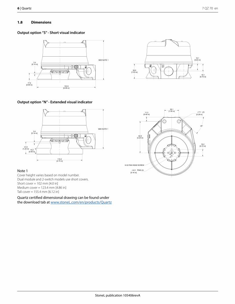
1.8 Dimensions
SEE NOTE 13.4
[0.14 in]
17.6[0.69 in]
153.9[6.06 in]
38.9[1.53 in]
16.1[0.63 in]
19.1[0.75 in]
45°
∅7.1[0.28 in]
(2)11.3[0.44 in]
38.1[1.50 in]
82.6[3.25 in]
18.2[0.72 in]
6-32 PAN HEAD SCREW
∅4.0[0.16 in]
PINS (2)
SEE NOTE 13.4
[0.14 in]
31.8[1.25 in]
119.4[4.70 in]
14.2
[0.56 in]
Note 1Cover height varies based on model number. Dual module and 2-switch models use short covers.Short cover = 102 mm [4.0 in]Medium cover = 123.4 mm [4.86 in]Tall cover = 155.4 mm [6.12 in]
Quartz certified dimensional drawing can be found under the download tab at www.stoneL.com/en/products/Quartz
Output option “S” - Short visual indicator
Output option “N” - Extended visual indicator
StoneL publication 105406revA
7 QZ 70 en Quartz | 7
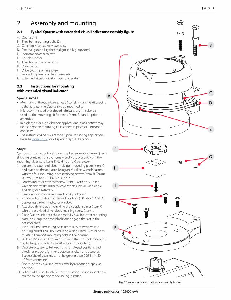
2 Assembly and mounting2.1 Typical Quartz with extended visual indicator assembly figureA. Quartz unitB. Thru-bolt mounting bolts (2)C. Cover lock (cast cover model only)D. External ground lug (Internal ground lug provided) E. Indicator cover setscrewF. Coupler spacerG. Thru-bolt retaining o-ringsH. Drive blockI. Drive block retaining screwJ. Mounting plate retaining screws (4)K. Extended visual indicator mounting plate
2.2 Instructions for mounting with extended visual indicator
Special notes:• Mounting of the Quartz requires a StoneL mounting kit specific
to the actuator the Quartz is to be mounted to.• It is recommended that thread lubricant or anti-seize be
used on the mounting kit fasteners (Items B, I and J) prior to assembly.
• In high cycle or high vibration applications, blue Loctite® may be used on the mounting kit fasteners in place of lubricant or anti-seize.
• The instructions below are for a typical mounting application. Refer to StoneL.com for kit specific layout drawings.
StepsQuartz unit and mounting kit are supplied separately. From Quartz shipping container, ensure items A and F are present. From the mounting kit, ensure items B, G, H, I, J and K are present. 1. Locate the extended visual indicator mounting plate (Item K)
and place on the actuator. Using an M4 allen wrench, fasten with the four mounting plate retaining screws (Item J). Torque screws to 25 to 30 in.lbs (2.8 to 3.4 Nm).
2. Loosen indicator cover setscrew (Item E) with an M2 allen wrench and rotate indicator cover to desired viewing angle and retighten setscrew.
3. Remove indicator drum screw from Quartz unit.4. Rotate indicator drum to desired position. (OPEN or CLOSED
appearing through indicator window.)5. Attached drive block (Item H) to the coupler spacer (Item F)
with the provided drive block retaining screw (Item I).6. Place Quartz unit onto the extended visual indicator mounting
plate, ensuring the drive block tabs engage the slot in the actuator shaft.
7. Slide Thru-bolt mounting bolts (Item B) with washers into housing and fit Thru-bolt retaining o-rings (Item G) over bolts to retain Thru-bolt mounting bolts in the housing.
8. With an 7/16“ socket, tighten down with the Thru-bolt mounting bolts. Torque bolts to 15 to 20 in.lbs (1.7 to 2.3 Nm).
9. Operate actuator to full open and full closed positions and check for proper alignment between switch and actuator. Eccentricity of shaft must not be greater than 0.254 mm [0.1 in] from centerline.
10. Fine-tune the visual indicator cover by repeating steps 2 as needed.
11. Follow additional Touch & Tune instructions found in section 4 related to the specific model being installed.
F
E
H
G
J
K
I
B
D
CA
Fig. 2.1 extended visual indicator assembly figure
7 QZ 70 en8 | Quartz
StoneL publication 105406revA
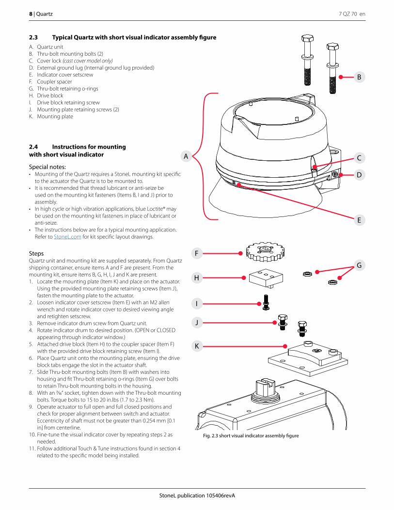
2.3 Typical Quartz with short visual indicator assembly figureA. Quartz unitB. Thru-bolt mounting bolts (2)C. Cover lock (cast cover model only)D. External ground lug (Internal ground lug provided) E. Indicator cover setscrewF. Coupler spacerG. Thru-bolt retaining o-ringsH. Drive blockI. Drive block retaining screwJ. Mounting plate retaining screws (2)K. Mounting plate
2.4 Instructions for mounting with short visual indicator
Special notes:• Mounting of the Quartz requires a StoneL mounting kit specific
to the actuator the Quartz is to be mounted to.• It is recommended that thread lubricant or anti-seize be
used on the mounting kit fasteners (Items B, I and J) prior to assembly.
• In high cycle or high vibration applications, blue Loctite® may be used on the mounting kit fasteners in place of lubricant or anti-seize.
• The instructions below are for a typical mounting application. Refer to StoneL.com for kit specific layout drawings.
StepsQuartz unit and mounting kit are supplied separately. From Quartz shipping container, ensure items A and F are present. From the mounting kit, ensure items B, G, H, I, J and K are present. 1. Locate the mounting plate (Item K) and place on the actuator.
Using the provided mounting plate retaining screws (Item J), fasten the mounting plate to the actuator.
2. Loosen indicator cover setscrew (Item E) with an M2 allen wrench and rotate indicator cover to desired viewing angle and retighten setscrew.
3. Remove indicator drum screw from Quartz unit.4. Rotate indicator drum to desired position. (OPEN or CLOSED
appearing through indicator window.)5. Attached drive block (Item H) to the coupler spacer (Item F)
with the provided drive block retaining screw (Item I).6. Place Quartz unit onto the mounting plate, ensuring the drive
block tabs engage the slot in the actuator shaft. 7. Slide Thru-bolt mounting bolts (Item B) with washers into
housing and fit Thru-bolt retaining o-rings (Item G) over bolts to retain Thru-bolt mounting bolts in the housing.
8. With an 7/16“ socket, tighten down with the Thru-bolt mounting bolts. Torque bolts to 15 to 20 in.lbs (1.7 to 2.3 Nm).
9. Operate actuator to full open and full closed positions and check for proper alignment between switch and actuator. Eccentricity of shaft must not be greater than 0.254 mm [0.1 in] from centerline.
10. Fine-tune the visual indicator cover by repeating steps 2 as needed.
11. Follow additional Touch & Tune instructions found in section 4 related to the specific model being installed.
J
K
F
E
H
G
I
B
D
CA
Fig. 2.3 short visual indicator assembly figure
StoneL publication 105406revA
7 QZ 70 en Quartz | 9
3 Maintenance, repair and installation3.1 Maintenance and repairMaintenance or repair of StoneL Quartz equipment must only be done by StoneL or by qualified personnel that are knowledgeable about the installation of electromechanical equipment in hazardous areas. All parts needed for repairs or maintenance must be purchased through a StoneL authorized distributor to maintain warranty and to ensure the safety and compliance of the equipment.No routine maintenance of StoneL Quartz units is required.
Attention: If required, the Quartz housing can be grounded to earth potential by either the internal or external ground lug. (See Assembly drawing 1.6 Item 5 on page 5, Figure 2.1 Item D on page 7, and Figure 2.3 Item D on page 8)
Attention: In order to maintain enclosure type and IP ratings, cover shall be tightened by hand until it stops on the surface of the base not to exceed 10 ft. lbs (13.5 Nm). Do not use any tool to tighten the cover.
3.2 Installation
Field wiring• It is the responsibility of the installer, or end user, to install this
product in accordance with the National Electrical Code (NFPA 70) or any other national or regional code defining proper practices.
• This product comes shipped with conduit covers in an effort to protect the internal components from debris during shipment and handling. It is the responsibility of the receiving and/or installing personnel to provide appropriate permanent sealing devices to prevent the intrusion of debris or moisture when stored or installed outdoors.
7 QZ 70 en10 | Quartz
StoneL publication 105406revA
Caution: To prevent ignition of hazardous atmospheres, replace cover before energizing the electrical circuits. Keep cover tightly closed within operation.
4 Function specific details4.1 Inductive proximity sensors
4.1.1 Dual module SST sensors (33)
Applicable models
QN33_, QX33_
Specifications
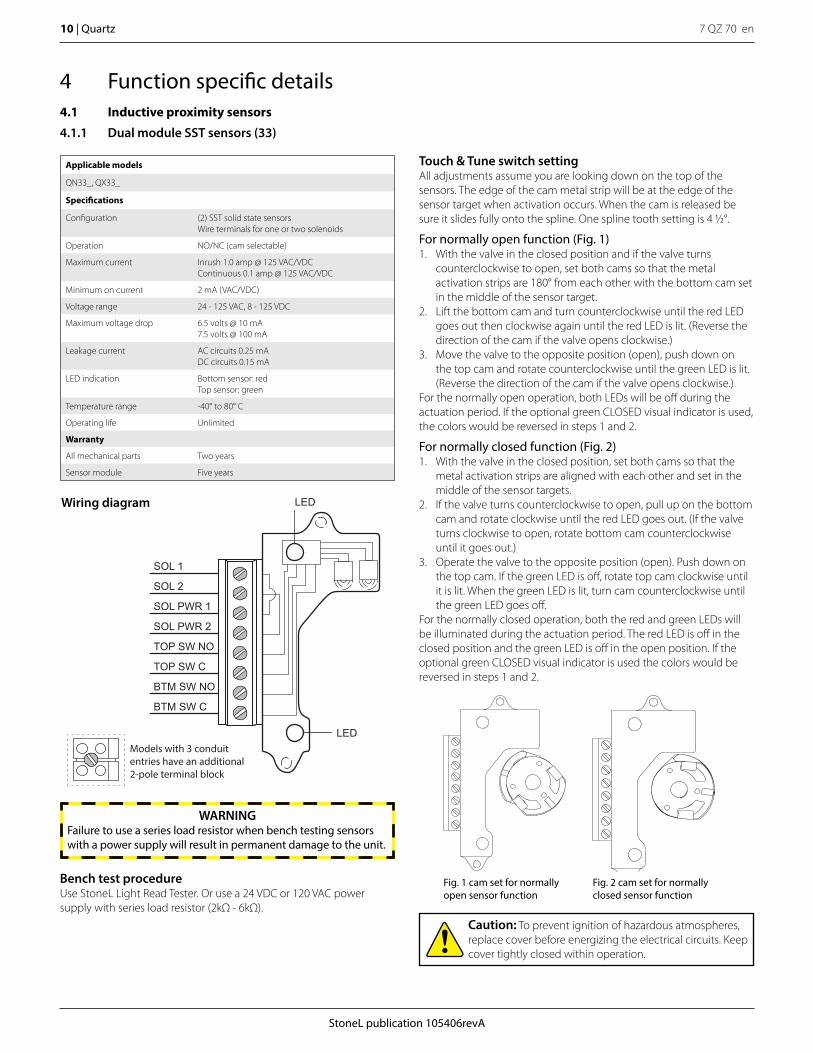
Configuration (2) SST solid state sensorsWire terminals for one or two solenoids
Operation NO/NC (cam selectable)
Maximum current Inrush 1.0 amp @ 125 VAC/VDCContinuous 0.1 amp @ 125 VAC/VDC
Minimum on current 2 mA (VAC/VDC)
Voltage range 24 - 125 VAC, 8 - 125 VDC
Maximum voltage drop 6.5 volts @ 10 mA 7.5 volts @ 100 mA
Leakage current AC circuits 0.25 mADC circuits 0.15 mA
LED indication Bottom sensor: redTop sensor: green
Temperature range -40° to 80° C
Operating life Unlimited
Warranty
All mechanical parts Two years
Sensor module Five years
LED
LED
SOL 1
SOL 2
SOL PWR 1
SOL PWR 2
TOP SW NO
TOP SW C
BTM SW NO
BTM SW C
Models with 3 conduit entries have an additional 2-pole terminal block
Wiring diagram
Touch & Tune switch settingAll adjustments assume you are looking down on the top of the sensors. The edge of the cam metal strip will be at the edge of the sensor target when activation occurs. When the cam is released be sure it slides fully onto the spline. One spline tooth setting is 4 1/2°.
For normally open function (Fig. 1)1. With the valve in the closed position and if the valve turns
counterclockwise to open, set both cams so that the metal activation strips are 180° from each other with the bottom cam set in the middle of the sensor target.
2. Lift the bottom cam and turn counterclockwise until the red LED goes out then clockwise again until the red LED is lit. (Reverse the direction of the cam if the valve opens clockwise.)
3. Move the valve to the opposite position (open), push down on the top cam and rotate counterclockwise until the green LED is lit. (Reverse the direction of the cam if the valve opens clockwise.)
For the normally open operation, both LEDs will be off during the actuation period. If the optional green CLOSED visual indicator is used, the colors would be reversed in steps 1 and 2.
For normally closed function (Fig. 2)1. With the valve in the closed position, set both cams so that the
metal activation strips are aligned with each other and set in the middle of the sensor targets.
2. If the valve turns counterclockwise to open, pull up on the bottom cam and rotate clockwise until the red LED goes out. (If the valve turns clockwise to open, rotate bottom cam counterclockwise until it goes out.)
3. Operate the valve to the opposite position (open). Push down on the top cam. If the green LED is off, rotate top cam clockwise until it is lit. When the green LED is lit, turn cam counterclockwise until the green LED goes off.
For the normally closed operation, both the red and green LEDs will be illuminated during the actuation period. The red LED is off in the closed position and the green LED is off in the open position. If the optional green CLOSED visual indicator is used the colors would be reversed in steps 1 and 2.
Fig. 1 cam set for normally open sensor function
Fig. 2 cam set for normally closed sensor function
Bench test procedureUse StoneL Light Read Tester. Or use a 24 VDC or 120 VAC power supply with series load resistor (2kΩ - 6kΩ).
WARNINGFailure to use a series load resistor when bench testing sensors with a power supply will result in permanent damage to the unit.
StoneL publication 105406revA
7 QZ 70 en Quartz | 11
Caution: To prevent ignition of hazardous atmospheres, replace cover before energizing the electrical circuits. Keep cover tightly closed within operation.
TOP SW LED(green)
BTM SW LED(red)
SOL 1
SOL 2
SOL PWR 1
SOL PWR 2
TOP SW NO
TOP SW C
BTM SW NO
BTM SW C
Models with 3 conduit entries have an additional 2-pole terminal block for second solenoid termination
Wiring diagram
4.1 Inductive proximity sensors
4.1.2 Dual module SST sensors (35)
Applicable models
QN35_, QX35_
Specifications
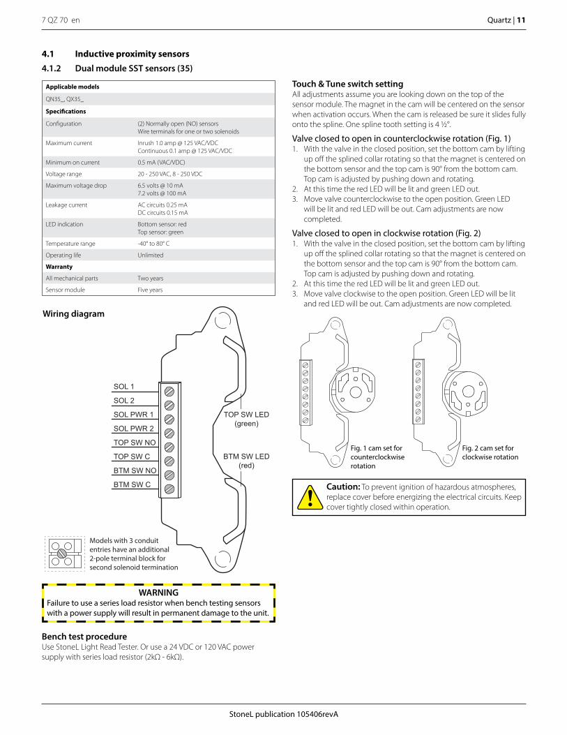
Configuration (2) Normally open (NO) sensorsWire terminals for one or two solenoids
Maximum current Inrush 1.0 amp @ 125 VAC/VDCContinuous 0.1 amp @ 125 VAC/VDC
Minimum on current 0.5 mA (VAC/VDC)
Voltage range 20 - 250 VAC, 8 - 250 VDC
Maximum voltage drop 6.5 volts @ 10 mA7.2 volts @ 100 mA
Leakage current AC circuits 0.25 mADC circuits 0.15 mA
LED indication Bottom sensor: redTop sensor: green
Temperature range -40° to 80° C
Operating life Unlimited
Warranty
All mechanical parts Two years
Sensor module Five years
Touch & Tune switch setting All adjustments assume you are looking down on the top of the sensor module. The magnet in the cam will be centered on the sensor when activation occurs. When the cam is released be sure it slides fully onto the spline. One spline tooth setting is 4 1/2°.
Valve closed to open in counterclockwise rotation (Fig. 1)1. With the valve in the closed position, set the bottom cam by lifting
up off the splined collar rotating so that the magnet is centered on the bottom sensor and the top cam is 90° from the bottom cam. Top cam is adjusted by pushing down and rotating.
2. At this time the red LED will be lit and green LED out.3. Move valve counterclockwise to the open position. Green LED
will be lit and red LED will be out. Cam adjustments are now completed.
Valve closed to open in clockwise rotation (Fig. 2)1. With the valve in the closed position, set the bottom cam by lifting
up off the splined collar rotating so that the magnet is centered on the bottom sensor and the top cam is 90° from the bottom cam. Top cam is adjusted by pushing down and rotating.
2. At this time the red LED will be lit and green LED out.3. Move valve clockwise to the open position. Green LED will be lit
and red LED will be out. Cam adjustments are now completed.
Bench test procedureUse StoneL Light Read Tester. Or use a 24 VDC or 120 VAC power supply with series load resistor (2kΩ - 6kΩ).
WARNINGFailure to use a series load resistor when bench testing sensors with a power supply will result in permanent damage to the unit.
Fig. 1 cam set for counterclockwise rotation
Fig. 2 cam set for clockwise rotation

7 QZ 70 en12 | Quartz
StoneL publication 105406revA
4.1 Inductive proximity sensors
4.1.3 SST solid state proximity senors (X)
Bench test procedureUse StoneL Light Read Tester. Or use a 24 VDC or 120 VAC power supply with series load resistor (2kΩ - 6kΩ).
Applicable models
Quartz with 2-wire inductive solid state QN_X_, QX_X_
Specifications
Configuration (2) SST solid state sensors
Operation NO/NC (cam selectable)
Maximum current Inrush 1.0 amp @ 125 VAC/VDCContinuous 0.1 amp @ 125 VAC/VDC
Minimum on current 0.5 mA (VAC/VDC)
Voltage range 24 - 125 VAC, 8 - 125 VDC
Maximum voltage drop 6.5 volts @ 10 mA7.5 volts @ 100 mA
Leakage current AC circuits 0.25 mADC circuits 0.15 mA
LED indication Bottom sensor: redTop sensor: green
Temperature range -40° to 80° C
Operating life Unlimited
Warranty
All mechanical parts Two years
Sensor module Five years
6 SST sensors (QN6X, QX6X)
Wiring diagrams
Unit has 2 vertically mounted 12-pole terminal blocks
fourth switch(red LED)
third switch(green LED)
second switch(red LED)
top switch(green LED)
bottom switch(red LED)
fifth switch(green LED)
C
NO/NC
C
NO/NC
C
NO/NC
C
NO/NC
C
NO/NC
C
NO/NC
SPA
RE
S
1012
12
34
56
79
118
5th
SW
4th
SW
3rd
SW
BTM
SW
2nd
SW
TOP
SW
CN
ON
CC
NO
NC
CN
ON
CC
NO
NC
CN
ON
CC
NO
NC
top switch (green LED)
bottom switch (red LED)
NO/NC
C
NO/NC
C
SPA
RE
S
12
34
56
78
BTM
SW
TOP S
W
CN
ON
CC
NO
NC
third switch (green LED)
bottom switch (red LED)
top switch (green LED)
second switch (red LED)
C
NO/NC
C
NO/NC
C
NO/NC
C
NO/NC
SPA
RE
S
12
34
BTM
SW
3rd SW
TOP S
W
CN
ON
CC
NO
NC
CN
ON
CC
NO
NC
2nd SW
2 SST sensors (QN2X, QX2X) 4 SST sensors (QN2X, QX2X)
WARNINGFailure to use a series load resistor when bench testing sensors with a power supply will result in permanent damage to the unit.
StoneL publication 105406revA
7 QZ 70 en Quartz | 13
4.1.3 SST solid state proximity senors (X) continued
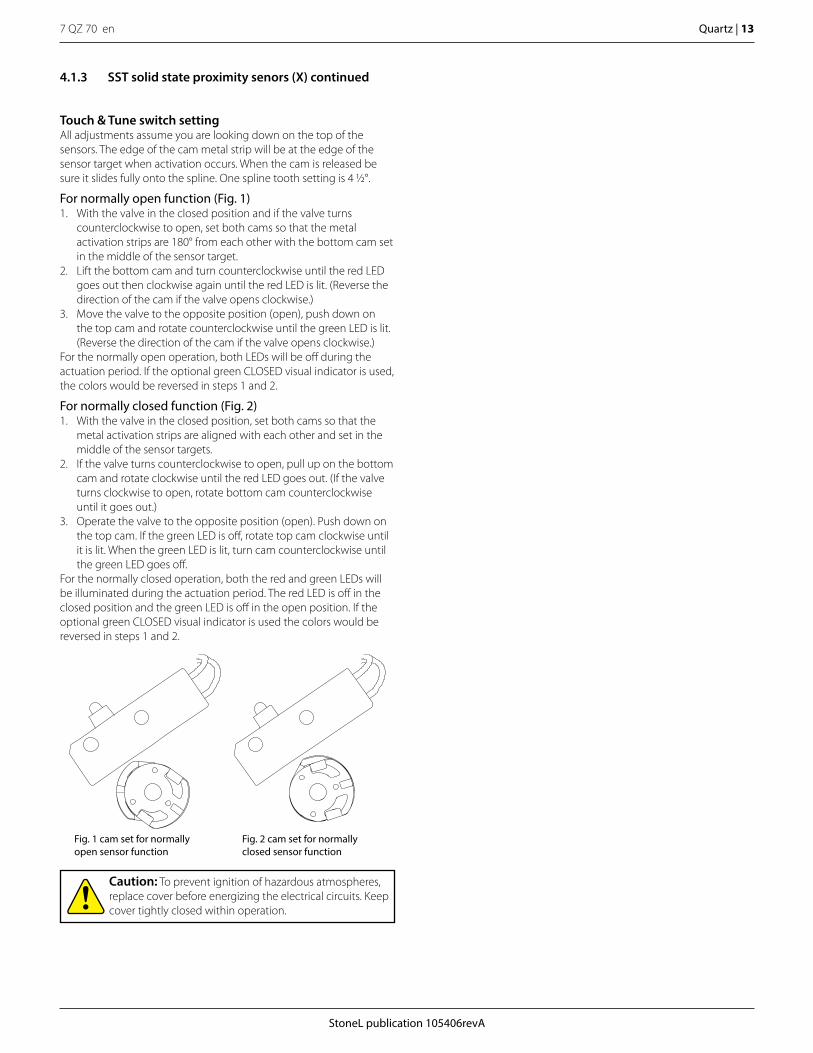
Touch & Tune switch settingAll adjustments assume you are looking down on the top of the sensors. The edge of the cam metal strip will be at the edge of the sensor target when activation occurs. When the cam is released be sure it slides fully onto the spline. One spline tooth setting is 4 1/2°.
For normally open function (Fig. 1)1. With the valve in the closed position and if the valve turns
counterclockwise to open, set both cams so that the metal activation strips are 180° from each other with the bottom cam set in the middle of the sensor target.
2. Lift the bottom cam and turn counterclockwise until the red LED goes out then clockwise again until the red LED is lit. (Reverse the direction of the cam if the valve opens clockwise.)
3. Move the valve to the opposite position (open), push down on the top cam and rotate counterclockwise until the green LED is lit. (Reverse the direction of the cam if the valve opens clockwise.)
For the normally open operation, both LEDs will be off during the actuation period. If the optional green CLOSED visual indicator is used, the colors would be reversed in steps 1 and 2.
For normally closed function (Fig. 2)1. With the valve in the closed position, set both cams so that the
metal activation strips are aligned with each other and set in the middle of the sensor targets.
2. If the valve turns counterclockwise to open, pull up on the bottom cam and rotate clockwise until the red LED goes out. (If the valve turns clockwise to open, rotate bottom cam counterclockwise until it goes out.)
3. Operate the valve to the opposite position (open). Push down on the top cam. If the green LED is off, rotate top cam clockwise until it is lit. When the green LED is lit, turn cam counterclockwise until the green LED goes off.
For the normally closed operation, both the red and green LEDs will be illuminated during the actuation period. The red LED is off in the closed position and the green LED is off in the open position. If the optional green CLOSED visual indicator is used the colors would be reversed in steps 1 and 2.
Fig. 1 cam set for normally open sensor function
Fig. 2 cam set for normally closed sensor function
Caution: To prevent ignition of hazardous atmospheres, replace cover before energizing the electrical circuits. Keep cover tightly closed within operation.
7 QZ 70 en14 | Quartz
StoneL publication 105406revA
4.1 Inductive proximity sensors
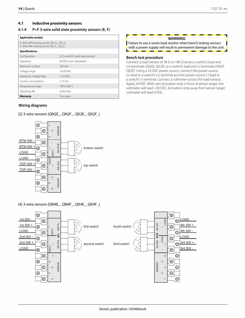
4.1.4 P+F 3-wire solid state proximity sensors (E, F)
Applicable models
3- Wire NPN sinking sensor QN_E_, QX_E_3- Wire PNP sinking sensor QN_F_, QX_F_
Specifications
Configuration (2) 3-wire DC solid state sensors
Operation NO/NC (cam selectable)
Maximum current 100 mA
Voltage range 10-30 VDC
Maximum voltage drop <2.0 VDC
Current consumption <15 mA
Temperature range -40° to 80° C
Operating life Unlimited
Warranty Two years
first switch fourth switch
third switchsecond switchLOAD
1st SW -
1st SW +
2nd SW -
LOAD
2nd SW +
3rd SW -
LOAD
4th SW +
LOAD
4th SW -
3rd SW +
SPA
RE
S
SPA
RE
S
-+
LOA
D
1st SW
-+
LOA
D1
2
TOP
35
4
4th
SW
3rd
SW
BTM
2nd SW
LOA
D+
-LO
AD
+-
54
32
1
(4) 3-wire sensors (QN4E_, QN4F_, QX4E_, QX4F_)
bottom switch
top switchTOP SW -
BTM SW -
BTM SW +
LOAD
LOAD
TOP SW +
SPA
RE
SS
PAR
ES
12
3- B
TM S
W
+LO
AD
LOA
D+
-
TOP S
W
46
5
(2) 3-wire sensors (QN2E_, QN2F_, QX2E_, QX2F_)
Wiring diagrams
Bench test procedureConnect a load resistor of 3K Ω to 10K Ω across a switch’s load and (+) terminals (QN2E, QX2E), or a switch’s load and (-) terminals (QN2F, QX2F). Using a 24 VDC power source, connect the power source (+) lead to a switch’s (+) terminal and the power source (-) lead to a switch’s (-) terminal. Connect a voltmeter across the load resistor. Apply 24 VDC. With cam activation strip in front of sensor target, the voltmeter will read >20 VDC. Activation strip away from sensor target voltmeter will read 0 VDC.
WARNINGFailure to use a series load resistor when bench testing sensors with a power supply will result in permanent damage to the unit.
StoneL publication 105406revA
7 QZ 70 en Quartz | 15
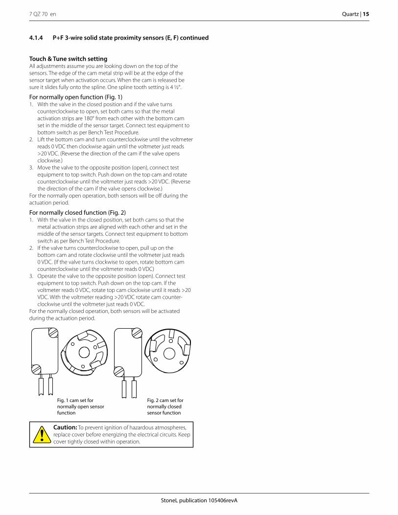
Touch & Tune switch settingAll adjustments assume you are looking down on the top of the sensors. The edge of the cam metal strip will be at the edge of the sensor target when activation occurs. When the cam is released be sure it slides fully onto the spline. One spline tooth setting is 4 1/2°.
For normally open function (Fig. 1)1. With the valve in the closed position and if the valve turns
counterclockwise to open, set both cams so that the metal activation strips are 180° from each other with the bottom cam set in the middle of the sensor target. Connect test equipment to bottom switch as per Bench Test Procedure.
2. Lift the bottom cam and turn counterclockwise until the voltmeter reads 0 VDC then clockwise again until the voltmeter just reads >20 VDC. (Reverse the direction of the cam if the valve opens clockwise.)
3. Move the valve to the opposite position (open), connect test equipment to top switch. Push down on the top cam and rotate counterclockwise until the voltmeter just reads >20 VDC. (Reverse the direction of the cam if the valve opens clockwise.)
For the normally open operation, both sensors will be off during the actuation period.
For normally closed function (Fig. 2)1. With the valve in the closed position, set both cams so that the
metal activation strips are aligned with each other and set in the middle of the sensor targets. Connect test equipment to bottom switch as per Bench Test Procedure.
2. If the valve turns counterclockwise to open, pull up on the bottom cam and rotate clockwise until the voltmeter just reads 0 VDC. (If the valve turns clockwise to open, rotate bottom cam counterclockwise until the voltmeter reads 0 VDC)
3. Operate the valve to the opposite position (open). Connect test equipment to top switch. Push down on the top cam. If the voltmeter reads 0 VDC, rotate top cam clockwise until it reads >20 VDC. With the voltmeter reading >20 VDC rotate cam counter-clockwise until the voltmeter just reads 0 VDC.
For the normally closed operation, both sensors will be activated during the actuation period.
Fig. 1 cam set for normally open sensor function
Fig. 2 cam set for normally closed sensor function
Caution: To prevent ignition of hazardous atmospheres, replace cover before energizing the electrical circuits. Keep cover tightly closed within operation.
4.1.4 P+F 3-wire solid state proximity sensors (E, F) continued
7 QZ 70 en16 | Quartz
StoneL publication 105406revA
4.2 Intrinsically safe inductive proximity switches
4.2.1 Dual module NAMUR sensors (44)
Applicable models
QN44_, QX44_
Specifications
Configuration (2) NAMUR sensors (EN 60947-5-6)Wire terminals for one or two solenoids
Operation NO/NC (cam selectable)
Voltage range 5 -25 VDC
Current ratings Target presentTarget absent
Current < 1.0 mA (LED = OFF)Current > 3.0 mA (LED = ON)
LED indication Bottom sensor: greenTop sensor: red
Temperature range -40° to 80° C
Operating life Unlimited
Warranty
All mechanical parts Two years
Sensor module Five years
Use with intrinsically safe repeater barrier. NAMUR sensors conform to EN 60947-5-6 standard.
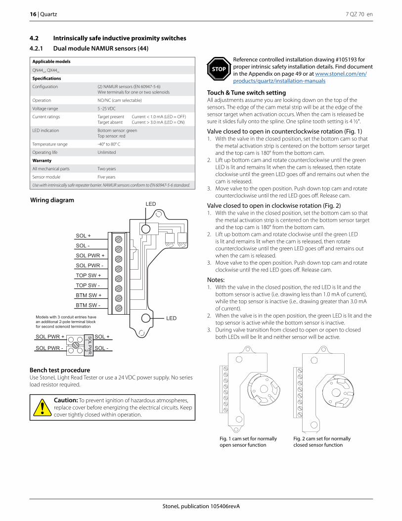
Touch & Tune switch settingAll adjustments assume you are looking down on the top of the sensors. The edge of the cam metal strip will be at the edge of the sensor target when activation occurs. When the cam is released be sure it slides fully onto the spline. One spline tooth setting is 4 1/2°.
Valve closed to open in counterclockwise rotation (Fig. 1)1. With the valve in the closed position, set the bottom cam so that
the metal activation strip is centered on the bottom sensor target and the top cam is 180° from the bottom cam.
2. Lift up bottom cam and rotate counterclockwise until the green LED is lit and remains lit when the cam is released, then rotate clockwise until the green LED goes off and remains out when the cam is released.
3. Move valve to the open position. Push down top cam and rotate counterclockwise until the red LED goes off. Release cam.
Valve closed to open in clockwise rotation (Fig. 2)1. With the valve in the closed position, set the bottom cam so that
the metal activation strip is centered on the bottom sensor target and the top cam is 180° from the bottom cam.
2. Lift up bottom cam and rotate clockwise until the green LED is lit and remains lit when the cam is released, then rotate counterclockwise until the green LED goes off and remains out when the cam is released.
3. Move valve to the open position. Push down top cam and rotate clockwise until the red LED goes off. Release cam.
Notes:1. With the valve in the closed position, the red LED is lit and the
bottom sensor is active (i.e. drawing less than 1.0 mA of current), while the top sensor is inactive (i.e.. drawing greater than 3.0 mA of current).
2. When the valve is in the open position, the green LED is lit and the top sensor is active while the bottom sensor is inactive.
3. During valve transition from closed to open or open to closed both LEDs will be lit and neither sensor will be active.
Bench test procedureUse StoneL Light Read Tester or use a 24 VDC power supply. No series load resistor required.
LED
LED
SOL +
SOL -
SOL PWR +
SOL PWR -
TOP SW +
TOP SW -
BTM SW +
BTM SW -
Models with 3 conduit entries have an additional 2-pole terminal block for second solenoid termination
SO
L PW
R21SOL PWR +
SOL PWR -
SOL +
SOL -
Wiring diagram
Caution: To prevent ignition of hazardous atmospheres, replace cover before energizing the electrical circuits. Keep cover tightly closed within operation.
Fig. 1 cam set for normally open sensor function
Fig. 2 cam set for normally closed sensor function
Reference controlled installation drawing #105193 for proper intrinsic safety installation details. Find document in the Appendix on page 49 or at www.stonel.com/en/products/quartz/installation-manuals
STOP
StoneL publication 105406revA
7 QZ 70 en Quartz | 17
Applicable models
QN45_, QX45_
Specifications
Configuration (2) NAMUR sensors (EN 60947-5-6)Wire terminals for one or two solenoids
Voltage range 5 - 25 VDC
Current ratings Target presentTarget absent
Current < 1.0 mA (LED = OFF)Current > 3.0 mA (LED = ON)
LED indication Bottom sensor: greenTop sensor: red
Temperature range -40° to 80° C
Operating life Unlimited
Warranty
All mechanical parts Two years
Sensor module Five years
Use with intrinsically safe repeater barrier. NAMUR sensors conform to EN 60947-5-6 standard.
Bench test procedureUse StoneL Light Read Tester or use a 24 VDC power supply. No series load resistor required.
TOP SW LED(red)
BTM SW LED(green)
SOL +
SOL -
SOL PWR +
SOL PWR -
TOP SW +
TOP SW -
BTM SW +
BTM SW -
Models with 3 conduit entries have an additional 2-pole terminal block for second solenoid termination
SO
L PW
R21SOL PWR +
SOL PWR -
SOL +
SOL -
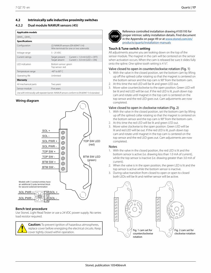
Wiring diagram
4.2 Intrinsically safe inductive proximity switches
4.2.2 Dual module NAMUR sensors (45)
Touch & Tune switch settingAll adjustments assume you are looking down on the top of the sensor module. The magnet in the cam will be centered on the sensor when activation occurs. When the cam is released be sure it slides fully onto the spline. One spline tooth setting is 4 1/2°.
Valve closed to open in counterclockwise rotation (Fig. 1)1. With the valve in the closed position, set the bottom cam by lifting
up off the splined collar rotating so that the magnet is centered on the bottom sensor and the top cam is 90° from the bottom cam.
2. At this time the red LED will be lit and green LED out.3. Move valve counterclockwise to the open position. Green LED will
be lit and red LED will be out. If the red LED is lit, push down top cam and rotate until magnet in the top cam is centered on the top sensor and the red LED goes out. Cam adjustments are now completed.
Valve closed to open in clockwise rotation (Fig. 2)1. With the valve in the closed position, set the bottom cam by lifting
up off the splined collar rotating so that the magnet is centered on the bottom sensor and the top cam is 90° from the bottom cam.
2. At this time the red LED will be lit and green LED out.3. Move valve clockwise to the open position. Green LED will be
lit and red LED will be out. If the red LED is lit, push down top cam and rotate until magnet in the top cam is centered on the top sensor and the red LED goes out. Cam adjustments are now completed.
Notes1. With the valve in the closed position, the red LED is lit and the
bottom sensor is active (i.e. drawing less than 1.0 mA of current), while the top sensor is inactive (i.e. drawing greater than 3.0 mA of current).
2. When the valve is in the open position, the green LED is lit and the top sensor is active while the bottom sensor is inactive.
3. During valve transition from closed to open or open to closed both LEDs will be lit and neither sensor will be active.
Caution: To prevent ignition of hazardous atmospheres, replace cover before energizing the electrical circuits. Keep cover tightly closed within operation.
Fig. 1 cam set for counterclockwise rotation
Fig. 2 cam set for clockwise rotation
Reference controlled installation drawing #105193 for proper intrinsic safety installation details. Find document in the Appendix on page 49 or at www.stonel.com/en/products/quartz/installation-manuals
STOP
7 QZ 70 en18 | Quartz
StoneL publication 105406revA
4.2 Intrinsically safe inductive proximity switches
4.2.3 P+F NAMUR sensors NJ2-12GK-SN (A)
Applicable models
QN_A_, QX_A_
Specifications
Configuration (2) NAMUR sensors (EN 60947-5-6)
Operation NO/NC (cam selectable)
Current ratings Target presentTarget absent
Current < 1.0 mA (LED = OFF)Current > 3.0 mA (LED = ON)
Voltage range 5 - 25 VDC
Temperature range -40° to 80° C
Operating life Unlimited
Warranty Two years
Use with intrinsically safe repeater barrier. NAMUR sensors conform to EN 60947-5-6 standard.
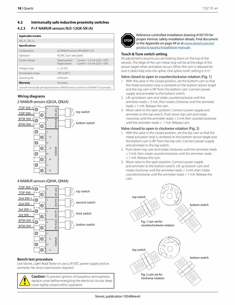
Touch & Tune switch settingAll adjustments assume you are looking down on the top of the sensors. The edge of the cam metal strip will be at the edge of the sensor target when activation occurs. When the cam is released be sure it slides fully onto the spline. One spline tooth setting is 4 1/2°.
Valve closed to open in counterclockwise rotation (Fig. 1)1. With the valve in the closed position, set the bottom cam so that
the metal activation strip is centered on the bottom sensor target and the top cam is 90° from the bottom cam. Connect power supply and ammeter to the bottom switch.
2. Lift up bottom cam and rotate counterclockwise until the ammeter reads > 3 mA, then rotate clockwise until the ammeter reads < 1 mA. Release the cam.
3. Move valve to the open position. Connect power supply and ammeter to the top switch. Push down top cam and rotate clockwise until the ammeter reads > 3 mA then counterclockwise until the ammeter reads < 1 mA. Release cam.
Valve closed to open in clockwise rotation (Fig. 2)1. With the valve in the closed position, set the top cam so that the
metal activation strip is centered on the bottom sensor target and the bottom cam is 90° from the top cam. Connect power supply and ammeter to the top switch.
2. Push down top cam and rotate clockwise until the ammeter reads > 3 mA, then rotate counterclockwise until the ammeter reads < 1 mA. Release the cam.
3. Move valve to the open position. Connect power supply and ammeter to the bottom switch. Lift up bottom cam and rotate clockwise until the ammeter reads > 3 mA, then rotate counterclockwise until the ammeter reads < 1 mA. Release the cam.
Fig. 1 cam set for counterclockwise rotation
top switch
bottom switch
Fig. 2 cam set for clockwise rotation
top switch
bottom switchBench test procedureUse StoneL Light Read Tester or use a 24 VDC power supply and an ammeter. No series load resistor required.
Wiring diagrams2 NAMUR sensors (QX2A, QN2A)
top switch
bottom switch
TOP SW +
TOP SW -
BTM SW +
BTM SW -
SPA
RE
S
12
34
56
78
BTM
SW
TOP S
W
-+
-+
Caution: To prevent ignition of hazardous atmospheres, replace cover before energizing the electrical circuits. Keep cover tightly closed within operation.
top switch
second switch
third switch
bottom switch
TOP SW +
TOP SW -
2nd SW +
2nd SW -
3rd SW +
3rd SW -
BTM SW +
BTM SW -
SPA
RE
S
+-
+-
12
34
2nd SW
3rd SW
BTM
SW
TOP S
W
-+
-+
4 NAMUR sensors (QX4A, QN4A)
Reference controlled installation drawing #105193 for proper intrinsic safety installation details. Find document in the Appendix on page 49 or at www.stonel.com/en/products/quartz/installation-manuals
STOP
StoneL publication 105406revA
7 QZ 70 en Quartz | 19
4.2 Intrinsically safe inductive proximity switches
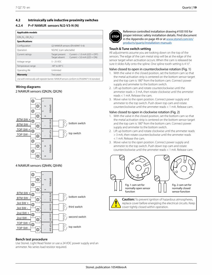
4.2.4 P+F NAMUR sensors NJ2-V3-N (N)
Applicable models
(QN_N_, QX_N_)
Specifications
Configuration (2) NAMUR sensors (EN 60947-5-6)
Operation NO/NC (cam selectable)
Current ratings Target presentTarget absent
Current < 1.0 mA (LED = OFF)Current > 3.0 mA (LED = ON)
Voltage range 5 - 25 VDC
Temperature range -40° to 80° C
Operating life Unlimited
Warranty Two years
Use with intrinsically safe repeater barrier. NAMUR sensors conform to EN 60947-5-6 standard.
Touch & Tune switch settingAll adjustments assume you are looking down on the top of the sensors. The edge of the cam metal strip will be at the edge of the sensor target when activation occurs. When the cam is released be sure it slides fully onto the spline. One spline tooth setting is 4 1/2°.
Valve closed to open in counterclockwise rotation (Fig. 1)1. With the valve in the closed position, set the bottom cam so that
the metal activation strip is centered on the bottom sensor target and the top cam is 180° from the bottom cam. Connect power supply and ammeter to the bottom switch.
2. Lift up bottom cam and rotate counterclockwise until the ammeter reads > 3 mA, then rotate clockwise until the ammeter reads < 1 mA. Release the cam.
3. Move valve to the open position. Connect power supply and ammeter to the top switch. Push down top cam and rotate counterclockwise until the ammeter reads < 1 mA. Release cam.
Valve closed to open in clockwise rotation (Fig. 2)1. With the valve in the closed position, set the bottom cam so that
the metal activation strip is centered on the bottom sensor target and the top cam is 180° from the bottom cam. Connect power supply and ammeter to the bottom switch.
2. Lift up bottom cam and rotate clockwise until the ammeter reads > 3 mA, then rotate counterclockwise until the ammeter reads < 1 mA. Release the cam.
3. Move valve to the open position. Connect power supply and ammeter to the top switch. Push down top cam and rotate counterclockwise until the ammeter reads < 1 mA. Release cam.
Bench test procedureUse StoneL Light Read Tester or use a 24 VDC power supply and an ammeter. No series load resistor required.
Wiring diagrams2 NAMUR sensors (QN2N, QX2N)
4 NAMUR sensors (QN4N, QX4N)
bottom switch
top switch
BTM SW +
BTM SW -
TOP SW +
TOP SW -
SPA
RE
SS
PAR
ES
+-
+-
56
78
12
34
TOP S
WB
TM S
W
bottom switch
third switch
second switch
top switch
BTM SW +
BTM SW -
3rd SW +
3rd SW -
2nd SW +
2nd SW -
TOP SW +
TOP SW -
+-
+-
3rd SW
2nd SW
TOP S
WB
TM S
W
-+
-+
SPA
RE
S
12
34
Caution: To prevent ignition of hazardous atmospheres, replace cover before energizing the electrical circuits. Keep cover tightly closed within operation.
Fig. 1 cam set for normally open sensor function
Fig. 2 cam set for normally closed sensor function
Reference controlled installation drawing #105193 for proper intrinsic safety installation details. Find document in the Appendix on page 49 or at www.stonel.com/en/products/quartz/installation-manuals
STOP
7 QZ 70 en20 | Quartz
StoneL publication 105406revA
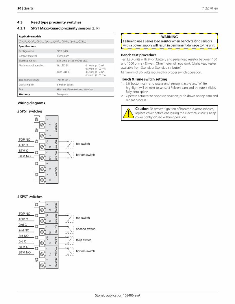
4.3 Reed type proximity switches
4.3.1 SPST Maxx-Guard proximity sensors (L, P)
Applicable models
(QN2P_, QX2P_, QN2L_, QX2L_, QN4P_, QX4P_, QN4L_, QX4L_)
Specifications
Configuration SPST (NO)
Contact material Ruthenium
Electrical ratings 0.15 amp @ 125 VAC/30 VDC
Maximum voltage drop No LED (P)
With LED (L)
0.1 volts @ 10 mA0.5 volts @ 100 mA3.5 volts @ 10 mA6.5 volts @ 100 mA
Temperature range -40° to 80° C
Operating life 5 million cycles
Seal Hermetically sealed reed switches
Warranty Two years
Wiring diagrams
2 SPST switches
top switch
bottom switch
TOP NO
TOP C
BTM C
BTM NO
56
78
BTM
SW
TOP S
W
NO
CC
NO
SPA
RE
SS
PAR
ES
12
34
4 SPST switches
top switch
second switch
third switch
bottom switch
TOP NO
TOP C
2nd C
2nd NO
3rd NO
3rd C
BTM C
BTM NO
CN
O3
4
3rd SW
2nd SW
TOP S
WB
TM S
W
CN
ON
OC
SPA
RE
SS
PAR
ES
12
NO
C
Touch & Tune switch setting1. Lift bottom cam and rotate until sensor is activated. (White
highlight will be next to sensor.) Release cam and be sure it slides fully onto spline.
2. Operate actuator to opposite position, push down on top cam and repeat process.
Caution: To prevent ignition of hazardous atmospheres, replace cover before energizing the electrical circuits. Keep cover tightly closed within operation.
Bench test procedureTest LED units with 9 volt battery and series load resistor between 150 and 1000 ohms - 1/2 watt. Ohm meter will not work. (Light Read tester available from StoneL or StoneL distributor.)Minimum of 3.5 volts required for proper switch operation.
WARNINGFailure to use a series load resistor when bench testing sensors with a power supply will result in permanent damage to the unit.
StoneL publication 105406revA
7 QZ 70 en Quartz | 21
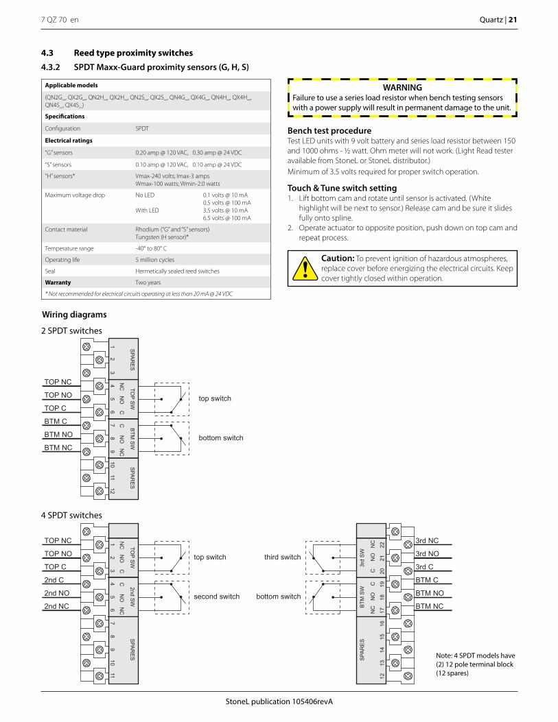
Applicable models
(QN2G_, QX2G_, QN2H_, QX2H_, QN2S_, QX2S_, QN4G_, QX4G_, QN4H_, QX4H_, QN4S_, QX4S_)
Specifications
Configuration SPDT
Electrical ratings
“G” sensors 0.20 amp @ 120 VAC, 0.30 amp @ 24 VDC
“S” sensors 0.10 amp @ 120 VAC, 0.10 amp @ 24 VDC
“H” sensors* Vmax-240 volts; Imax-3 ampsWmax-100 watts; Wmin-2.0 watts
Maximum voltage drop No LED
With LED
0.1 volts @ 10 mA0.5 volts @ 100 mA3.5 volts @ 10 mA6.5 volts @ 100 mA
Contact material Rhodium (“G” and “S” sensors)Tungsten (H sensor)*
Temperature range -40° to 80° C
Operating life 5 million cycles
Seal Hermetically sealed reed switches
Warranty Two years
* Not recommended for electrical circuits operating at less than 20 mA @ 24 VDC
4.3 Reed type proximity switches
4.3.2 SPDT Maxx-Guard proximity sensors (G, H, S)
Wiring diagrams
top switch
bottom switchBTM NC
TOP NC
TOP NO
BTM C
TOP C
BTM NOS
PAR
ES
SPA
RE
S
12
34
TOP S
W
56
NC
NC
NO
NO
CC7
89
BTM
SW
1012
11
Note: 4 SPDT models have (2) 12 pole terminal block (12 spares)
top switch
second switch
TOP C
2nd C
2nd NC
2nd NO
TOP NO
TOP NC
SPA
RE
S
12
34
TOP S
W
56
NC
NC
NO
NO
CC
78
9
2nd SW
1011
third switch
bottom switch
BTM C
BTM NO
BTM NC
3rd C
3rd NC
3rd NO
SPA
RE
S
1213
1415
BTM
SW
1617
NO
CN
CC
NC
NO
1819
20
3rd
SW
2122
Touch & Tune switch setting1. Lift bottom cam and rotate until sensor is activated. (White
highlight will be next to sensor.) Release cam and be sure it slides fully onto spline.
2. Operate actuator to opposite position, push down on top cam and repeat process.
Caution: To prevent ignition of hazardous atmospheres, replace cover before energizing the electrical circuits. Keep cover tightly closed within operation.
Bench test procedureTest LED units with 9 volt battery and series load resistor between 150 and 1000 ohms - 1/2 watt. Ohm meter will not work. (Light Read tester available from StoneL or StoneL distributor.)Minimum of 3.5 volts required for proper switch operation.
WARNINGFailure to use a series load resistor when bench testing sensors with a power supply will result in permanent damage to the unit.
2 SPDT switches
4 SPDT switches
7 QZ 70 en22 | Quartz
StoneL publication 105406revA
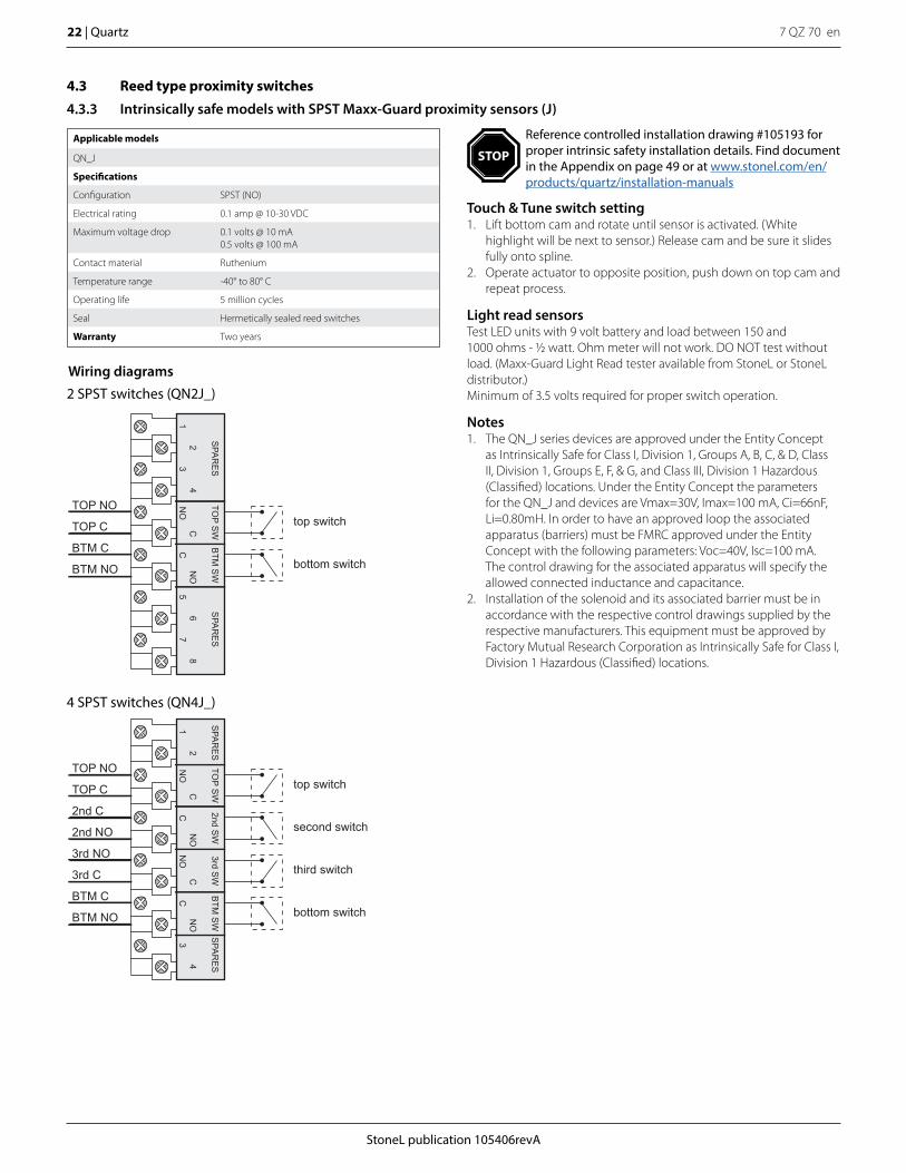
4.3 Reed type proximity switches
4.3.3 Intrinsically safe models with SPST Maxx-Guard proximity sensors (J)
Applicable models
QN_J
Specifications
Configuration SPST (NO)
Electrical rating 0.1 amp @ 10-30 VDC
Maximum voltage drop 0.1 volts @ 10 mA0.5 volts @ 100 mA
Contact material Ruthenium
Temperature range -40° to 80° C
Operating life 5 million cycles
Seal Hermetically sealed reed switches
Warranty Two years
Light read sensorsTest LED units with 9 volt battery and load between 150 and 1000 ohms - 1/2 watt. Ohm meter will not work. DO NOT test without load. (Maxx-Guard Light Read tester available from StoneL or StoneL distributor.)Minimum of 3.5 volts required for proper switch operation.
Wiring diagrams2 SPST switches (QN2J_)
4 SPST switches (QN4J_)
top switch
bottom switch
TOP NO
TOP C
BTM C
BTM NO
56
78
BTM
SW
TOP S
W
NO
CC
NO
SPA
RE
SS
PAR
ES
12
34
top switch
second switch
third switch
bottom switch
TOP NO
TOP C
2nd C
2nd NO
3rd NO
3rd C
BTM C
BTM NO
CN
O3
4
3rd SW
2nd SW
TOP S
WB
TM S
W
CN
ON
OC
SPA
RE
SS
PAR
ES
12
NO
C
Notes1. The QN_J series devices are approved under the Entity Concept
as Intrinsically Safe for Class I, Division 1, Groups A, B, C, & D, Class II, Division 1, Groups E, F, & G, and Class III, Division 1 Hazardous (Classified) locations. Under the Entity Concept the parameters for the QN_J and devices are Vmax=30V, Imax=100 mA, Ci=66nF, Li=0.80mH. In order to have an approved loop the associated apparatus (barriers) must be FMRC approved under the Entity Concept with the following parameters: Voc=40V, Isc=100 mA. The control drawing for the associated apparatus will specify the allowed connected inductance and capacitance.
2. Installation of the solenoid and its associated barrier must be in accordance with the respective control drawings supplied by the respective manufacturers. This equipment must be approved by Factory Mutual Research Corporation as Intrinsically Safe for Class I, Division 1 Hazardous (Classified) locations.
Touch & Tune switch setting1. Lift bottom cam and rotate until sensor is activated. (White
highlight will be next to sensor.) Release cam and be sure it slides fully onto spline.
2. Operate actuator to opposite position, push down on top cam and repeat process.
Reference controlled installation drawing #105193 for proper intrinsic safety installation details. Find document in the Appendix on page 49 or at www.stonel.com/en/products/quartz/installation-manuals
STOP

StoneL publication 105406revA
7 QZ 70 en Quartz | 23
4.3 Reed type proximity switches
4.3.4 Intrinsically safe models with SPDT Maxx-Guard proximity sensors (M)
Applicable models
QN_M
Specifications
Configuration SPDT; passive (intrinsically safe)
Electrical rating 0.1 amp @ 10-30 VDC
Maximum voltage drop 0.1 volts @ 10 mA0.5 volts @ 100 mA
Contact material Rhodium
Temperature range -40° to 80° C
Operating life 5 million cycles
Seal Hermetically sealed reed switches
Warranty Two years
Light read sensorsTest LED units with 9 volt battery and load between 150 and 1000 ohms - 1/2 watt. Ohm meter will not work. DO NOT test without load. (Maxx-Guard Light Read tester available from StoneL or StoneL distributor.)Minimum of 3.5 volts required for proper switch operation.
top switch
second switch
TOP C
2nd C
2nd NC
2nd NO
TOP NO
TOP NC
SPA
RE
S
12
34
TOP S
W
56
NC
NC
NO
NO
CC
78
9
2nd SW
1011
third switch
bottom switch
BTM C
BTM NO
BTM NC
3rd C
3rd NC
3rd NO
SPA
RE
S
1213
1415
BTM
SW
1617
NO
CN
CC
NC
NO
1819
20
3rd
SW
2122
Wiring diagrams2 SPDT switches (QN2M_)
top switch
bottom switchBTM NC
TOP NC
TOP NO
BTM C
TOP C
BTM NO
SPA
RE
SS
PAR
ES
12
34
TOP S
W
56
NC
NC
NO
NO
CC7
89
BTM
SW
1012
11
4 SPDT switches (QN4M_)
Note: 4 SPDT models have (2) 12 pole terminal block (12 spares)
Touch & Tune switch setting1. Lift bottom cam and rotate until sensor is activated. (White
highlight will be next to sensor.) Release cam and be sure it slides fully onto spline.
2. Operate actuator to opposite position, push down on top cam and repeat process.
Reference controlled installation drawing #105193 for proper intrinsic safety installation details. Find document in the Appendix on page 49 or at www.stonel.com/en/products/quartz/installation-manuals
STOP
7 QZ 70 en24 | Quartz
StoneL publication 105406revA
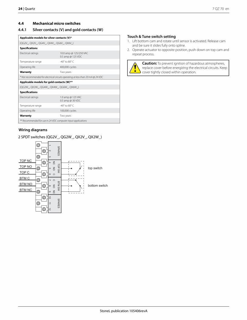
Applicable models for silver contacts (V)*
(QG2V_, QX2V_, QG4V_, QX4V_, QG6V_, QX6V_)
Specifications
Electrical ratings 10.0 amp @ 125/250 VAC0.5 amp @ 125 VDC
Temperature range -40° to 80° C
Operating life 400,000 cycles
Warranty Two years
* Not recommended for electrical circuits operating at less than 20 mA @ 24 VDC
Applicable models for gold contacts (W)**
(QG2W_, QX2W_, QG4W_, QX4W_, QG6W_, QX6W_)
Specifications
Electrical ratings 1.0 amp @ 125 VAC0.5 amp @ 30 VDC
Temperature range -40° to 80° C
Operating life 100,000 cycles
Warranty Two years
** Recommended for use in 24 VDC computer input applications
4.4 Mechanical micro switches
4.4.1 Silver contacts (V) and gold contacts (W)
top switch
bottom switchBTM NC
TOP NC
TOP NO
BTM C
TOP C
BTM NOS
PAR
ES
SPA
RE
S
12
34
TOP S
W
56
NC
NC
NO
NO
CC7
89
BTM
SW
1012
11
Wiring diagrams
2 SPDT switches (QG2V_, QG2W_, QX2V_, QX2W_)
Touch & Tune switch setting1. Lift bottom cam and rotate until sensor is activated. Release cam
and be sure it slides fully onto spline.2. Operate actuator to opposite position, push down on top cam and
repeat process.
Caution: To prevent ignition of hazardous atmospheres, replace cover before energizing the electrical circuits. Keep cover tightly closed within operation.
StoneL publication 105406revA
7 QZ 70 en Quartz | 25
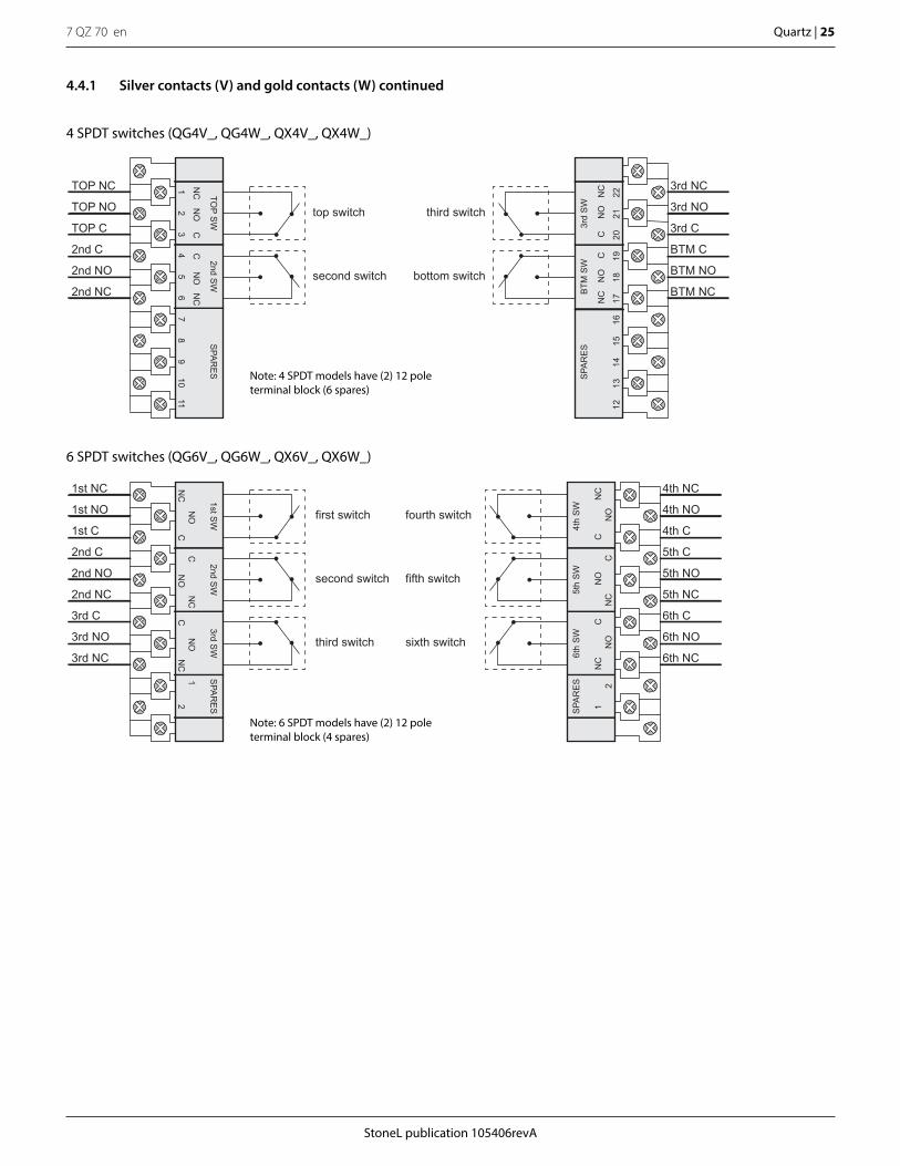
4.4.1 Silver contacts (V) and gold contacts (W) continued
6 SPDT switches (QG6V_, QG6W_, QX6V_, QX6W_)
4 SPDT switches (QG4V_, QG4W_, QX4V_, QX4W_)
first switch
second switch
third switch
fourth switch
fifth switch
sixth switch
1st C
2nd C
2nd NC
2nd NO
3rd C
3rd NC
3rd NO
1st NO
1st NC
5th C
5th NO
5th NC
6th C
6th NO
6th NC
4th C
4th NC
4th NO
NC
12
3rd SW
2nd SW
NO
CN
CN
O
1st SW
SPA
RE
S
NC
NO
CC
NC
12
4th
SW
5th
SW
NO
CC
NO
6th
SW
SPA
RE
S
NC
NO
CN
C
top switch
second switch
TOP C
2nd C
2nd NC
2nd NO
TOP NO
TOP NC
SPA
RE
S
12
34
TOP S
W
56
NC
NC
NO
NO
CC
78
9
2nd SW
1011
third switch
bottom switch
BTM C
BTM NO
BTM NC
3rd C
3rd NC
3rd NO
SPA
RE
S
1213
1415
BTM
SW
1617
NO
CN
CC
NC
NO
1819
20
3rd
SW
2122
Note: 4 SPDT models have (2) 12 pole terminal block (6 spares)
Note: 6 SPDT models have (2) 12 pole terminal block (4 spares)

7 QZ 70 en26 | Quartz
StoneL publication 105406revA
Wiring diagram
2 DPDT switches (QG14_, QX14_)
Applicable models
QG14_, QX14_
Specifications
Electrical ratings 4.5 amp @ 125/250 VAC, 24 to 125 VDC
Temperature range -40° to 80° C
Operating life 250,000 (VAC), 100,000 (VDC) cycles
Warranty Two years
Not recommended for electrical circuits operating at less than 20 mA @ 24 VDC
4.4 Mechanical micro switches
4.4.2 DPDT switches (14)
TOP C1
TOP C2
TOP NC1
TOP NO1
TOP NO2
TOP NC2
BTM NC1
BTM NO1
BTM C1
BTM C2
BTM NO2
BTM NC2
C1
C2
NO
2N
C2
BTM
NO
1N
C1
NC
2N
O2
TOP
NC
1N
O1
C1
C2
top switch(individual elements actuate
with common plunger)
bottom switch(individual elements actuate
with common plunger)
Additional 3-poleterminal blockprovided in unitfor solenoid termination
Caution: To prevent ignition of hazardous atmospheres, replace cover before energizing the electrical circuits. Keep cover tightly closed within operation.
Touch & Tune switch setting1. Lift bottom cam and rotate until sensor is activated. Release cam
and be sure it slides fully onto spline.2. Operate actuator to opposite position, push down on top cam and
repeat process.

StoneL publication 105406revA
7 QZ 70 en Quartz | 27
7 QZ 70 en28 | Quartz
StoneL publication 105406revA
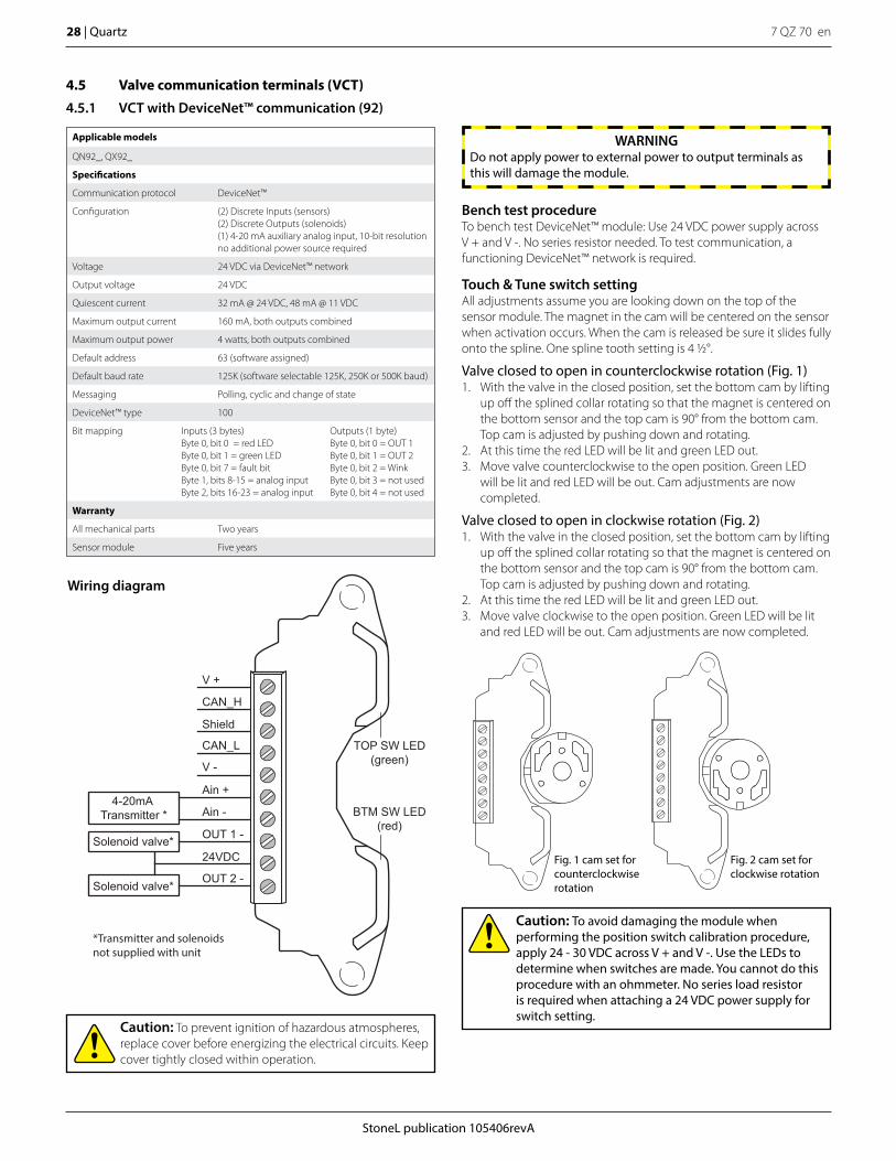
4.5 Valve communication terminals (VCT)
4.5.1 VCT with DeviceNet™ communication (92)
Applicable models
QN92_, QX92_
Specifications
Communication protocol DeviceNet™
Configuration (2) Discrete Inputs (sensors)(2) Discrete Outputs (solenoids)(1) 4-20 mA auxiliary analog input, 10-bit resolutionno additional power source required
Voltage 24 VDC via DeviceNet™ network
Output voltage 24 VDC
Quiescent current 32 mA @ 24 VDC, 48 mA @ 11 VDC
Maximum output current 160 mA, both outputs combined
Maximum output power 4 watts, both outputs combined
Default address 63 (software assigned)
Default baud rate 125K (software selectable 125K, 250K or 500K baud)
Messaging Polling, cyclic and change of state
DeviceNet™ type 100
Bit mapping Inputs (3 bytes)Byte 0, bit 0 = red LEDByte 0, bit 1 = green LEDByte 0, bit 7 = fault bitByte 1, bits 8-15 = analog inputByte 2, bits 16-23 = analog input
Outputs (1 byte)Byte 0, bit 0 = OUT 1Byte 0, bit 1 = OUT 2Byte 0, bit 2 = WinkByte 0, bit 3 = not usedByte 0, bit 4 = not used
Warranty
All mechanical parts Two years
Sensor module Five years
Caution: To prevent ignition of hazardous atmospheres, replace cover before energizing the electrical circuits. Keep cover tightly closed within operation.
Wiring diagram
TOP SW LED(green)
BTM SW LED(red)
V +
CAN_H
Shield
CAN_L
V -
Ain +
Ain -
OUT 1 -
24VDC
OUT 2 -Solenoid valve*
Solenoid valve*
4-20mA Transmitter *
*Transmitter and solenoidsnot supplied with unit
Bench test procedureTo bench test DeviceNet™ module: Use 24 VDC power supply across V + and V -. No series resistor needed. To test communication, a functioning DeviceNet™ network is required.
Caution: To avoid damaging the module when performing the position switch calibration procedure, apply 24 - 30 VDC across V + and V -. Use the LEDs to determine when switches are made. You cannot do this procedure with an ohmmeter. No series load resistor is required when attaching a 24 VDC power supply for switch setting.
Touch & Tune switch setting All adjustments assume you are looking down on the top of the sensor module. The magnet in the cam will be centered on the sensor when activation occurs. When the cam is released be sure it slides fully onto the spline. One spline tooth setting is 4 1/2°.
Valve closed to open in counterclockwise rotation (Fig. 1)1. With the valve in the closed position, set the bottom cam by lifting
up off the splined collar rotating so that the magnet is centered on the bottom sensor and the top cam is 90° from the bottom cam. Top cam is adjusted by pushing down and rotating.
2. At this time the red LED will be lit and green LED out.3. Move valve counterclockwise to the open position. Green LED
will be lit and red LED will be out. Cam adjustments are now completed.
Valve closed to open in clockwise rotation (Fig. 2)1. With the valve in the closed position, set the bottom cam by lifting
up off the splined collar rotating so that the magnet is centered on the bottom sensor and the top cam is 90° from the bottom cam. Top cam is adjusted by pushing down and rotating.
2. At this time the red LED will be lit and green LED out.3. Move valve clockwise to the open position. Green LED will be lit
and red LED will be out. Cam adjustments are now completed.
WARNINGDo not apply power to external power to output terminals as this will damage the module.
Fig. 1 cam set for counterclockwise rotation
Fig. 2 cam set for clockwise rotation

StoneL publication 105406revA
7 QZ 70 en Quartz | 29
4.5.1 VCT with DeviceNet™ communication (92) continued
DeviceNet™ Wink feature The Wink feature provides the capability of setting the CLOSED and OPEN LEDs to simultaneously flash or wink at a 2 Hz rate. This feature aids in physically locating the unit on the network.
1. DeviceNet™ communications are required in order to set the Wink feature. The unit must be addressed and correctly configured to be recognized by the control system.
2. Set byte 0, bit 2 to 1 in the desired unit. Once the correct unit has been physically located on the network, indicated by the winking of the CLOSED and OPEN LEDs, set byte 0 bit 2 back to 0. Performing this function will not change the closed and open sensor setpoints.
Quartz with DeviceNet™ Fault Bit (input byte 0, bit 7)1. The Fault indication will set to a 1 when input byte 0, bits 0 and 1
are set to 1 at the same time.2. When input byte 0, bits 0 and 1 are both set to 1, this would
indicate that the valve is both open and closed at the same time. This would be an abnormal or Fault condition.
7 QZ 70 en30 | Quartz
StoneL publication 105406revA
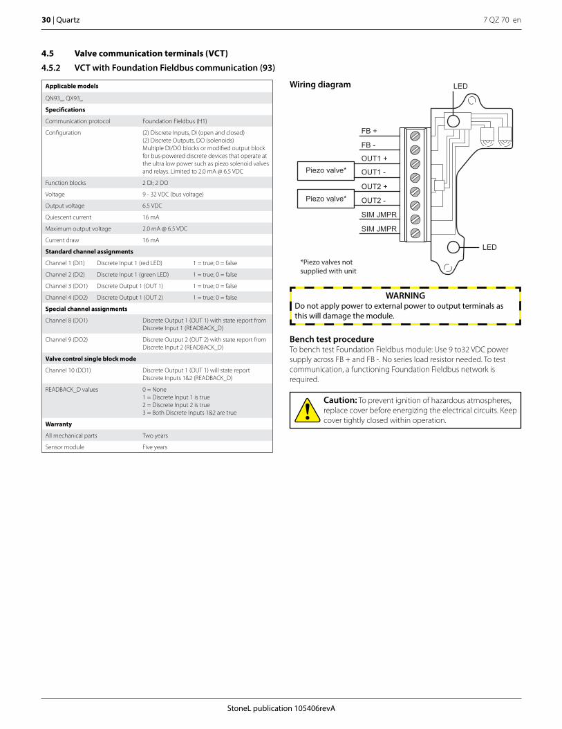
4.5 Valve communication terminals (VCT)
4.5.2 VCT with Foundation Fieldbus communication (93)
Applicable models
QN93_, QX93_
Specifications
Communication protocol Foundation Fieldbus (H1)
Configuration (2) Discrete Inputs, DI (open and closed)(2) Discrete Outputs, DO (solenoids)Multiple DI/DO blocks or modified output blockfor bus-powered discrete devices that operate at the ultra low power such as piezo solenoid valves and relays. Limited to 2.0 mA @ 6.5 VDC
Function blocks 2 DI; 2 DO
Voltage 9 - 32 VDC (bus voltage)
Output voltage 6.5 VDC
Quiescent current 16 mA
Maximum output voltage 2.0 mA @ 6.5 VDC
Current draw 16 mA
Standard channel assignments
Channel 1 (DI1) Discrete Input 1 (red LED) 1 = true; 0 = false
Channel 2 (DI2) Discrete Input 1 (green LED) 1 = true; 0 = false
Channel 3 (DO1) Discrete Output 1 (OUT 1) 1 = true; 0 = false
Channel 4 (DO2) Discrete Output 1 (OUT 2) 1 = true; 0 = false
Special channel assignments
Channel 8 (DO1) Discrete Output 1 (OUT 1) with state report from Discrete Input 1 (READBACK_D)
Channel 9 (DO2) Discrete Output 2 (OUT 2) with state report from Discrete Input 2 (READBACK_D)
Valve control single block mode
Channel 10 (DO1) Discrete Output 1 (OUT 1) will state report Discrete Inputs 1&2 (READBACK_D)
READBACK_D values 0 = None1 = Discrete Input 1 is true2 = Discrete Input 2 is true3 = Both Discrete Inputs 1&2 are true
Warranty
All mechanical parts Two years
Sensor module Five years
Bench test procedureTo bench test Foundation Fieldbus module: Use 9 to32 VDC power supply across FB + and FB -. No series load resistor needed. To test communication, a functioning Foundation Fieldbus network is required.
LED
LED
FB +
FB -
OUT1 +
OUT1 -
OUT2 +
OUT2 -
SIM JMPR
SIM JMPR
Piezo valve*
Piezo valve*
*Piezo valves notsupplied with unit
Wiring diagram
Caution: To prevent ignition of hazardous atmospheres, replace cover before energizing the electrical circuits. Keep cover tightly closed within operation.
WARNINGDo not apply power to external power to output terminals as this will damage the module.
StoneL publication 105406revA
7 QZ 70 en Quartz | 31
Caution: To avoid damaging the module when performing the position switch calibration procedure, apply 9 - 32 VDC across FB + and FB -. Use the LEDs to determine when switches are made. You cannot do this procedure with an ohmmeter. No series load resistor is required when attaching a 24 VDC power supply for switch setting.
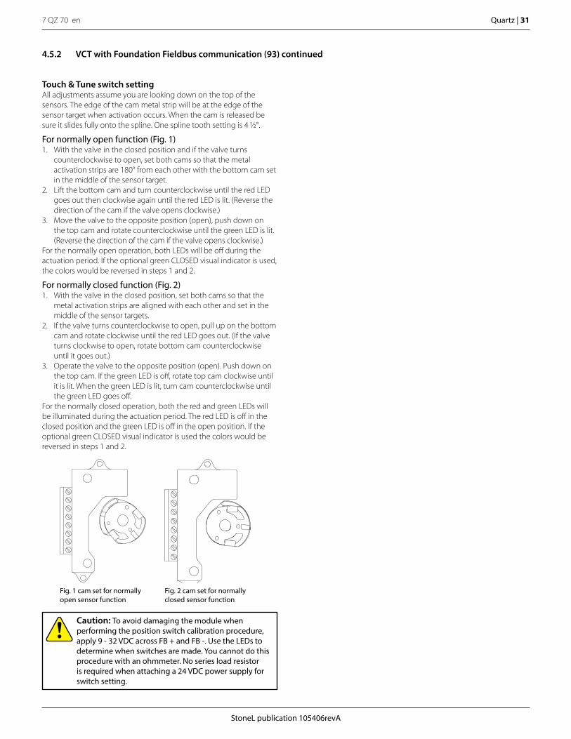
Touch & Tune switch settingAll adjustments assume you are looking down on the top of the sensors. The edge of the cam metal strip will be at the edge of the sensor target when activation occurs. When the cam is released be sure it slides fully onto the spline. One spline tooth setting is 4 1/2°.
For normally open function (Fig. 1)1. With the valve in the closed position and if the valve turns
counterclockwise to open, set both cams so that the metal activation strips are 180° from each other with the bottom cam set in the middle of the sensor target.
2. Lift the bottom cam and turn counterclockwise until the red LED goes out then clockwise again until the red LED is lit. (Reverse the direction of the cam if the valve opens clockwise.)
3. Move the valve to the opposite position (open), push down on the top cam and rotate counterclockwise until the green LED is lit. (Reverse the direction of the cam if the valve opens clockwise.)
For the normally open operation, both LEDs will be off during the actuation period. If the optional green CLOSED visual indicator is used, the colors would be reversed in steps 1 and 2.
For normally closed function (Fig. 2)1. With the valve in the closed position, set both cams so that the
metal activation strips are aligned with each other and set in the middle of the sensor targets.
2. If the valve turns counterclockwise to open, pull up on the bottom cam and rotate clockwise until the red LED goes out. (If the valve turns clockwise to open, rotate bottom cam counterclockwise until it goes out.)
3. Operate the valve to the opposite position (open). Push down on the top cam. If the green LED is off, rotate top cam clockwise until it is lit. When the green LED is lit, turn cam counterclockwise until the green LED goes off.
For the normally closed operation, both the red and green LEDs will be illuminated during the actuation period. The red LED is off in the closed position and the green LED is off in the open position. If the optional green CLOSED visual indicator is used the colors would be reversed in steps 1 and 2.
Fig. 1 cam set for normally open sensor function
Fig. 2 cam set for normally closed sensor function
4.5.2 VCT with Foundation Fieldbus communication (93) continued
7 QZ 70 en32 | Quartz
StoneL publication 105406revA
4.5 Valve communication terminals (VCT)
4.5.3 VCT with AS- Interface communication (96)
Applicable models
QN96_, QX96_
Specifications
Communication protocol AS- Interface
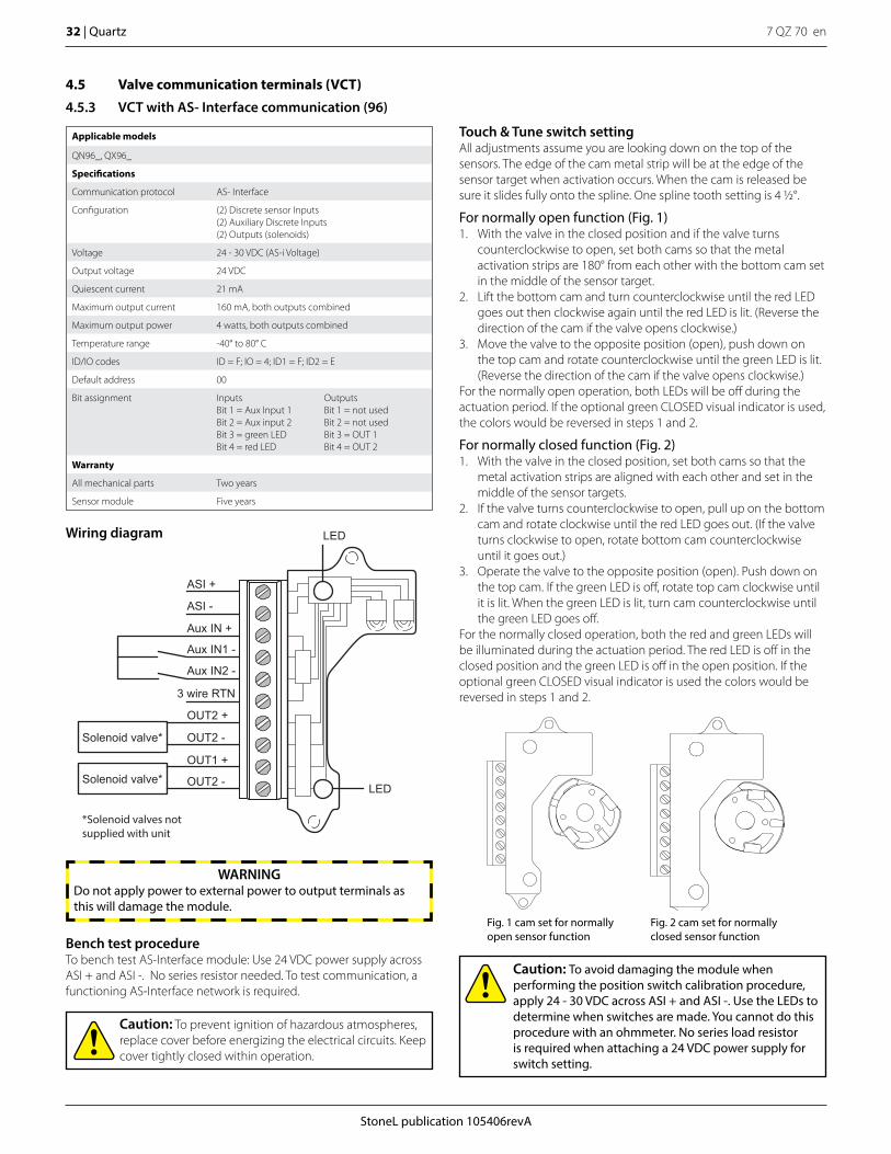
Configuration (2) Discrete sensor Inputs(2) Auxiliary Discrete Inputs(2) Outputs (solenoids)
Voltage 24 - 30 VDC (AS-i Voltage)
Output voltage 24 VDC
Quiescent current 21 mA
Maximum output current 160 mA, both outputs combined
Maximum output power 4 watts, both outputs combined
Temperature range -40° to 80° C
ID/IO codes ID = F; IO = 4; ID1 = F; ID2 = E
Default address 00
Bit assignment InputsBit 1 = Aux Input 1Bit 2 = Aux input 2Bit 3 = green LEDBit 4 = red LED
OutputsBit 1 = not usedBit 2 = not usedBit 3 = OUT 1Bit 4 = OUT 2
Warranty
All mechanical parts Two years
Sensor module Five years
Touch & Tune switch settingAll adjustments assume you are looking down on the top of the sensors. The edge of the cam metal strip will be at the edge of the sensor target when activation occurs. When the cam is released be sure it slides fully onto the spline. One spline tooth setting is 4 1/2°.
For normally open function (Fig. 1)1. With the valve in the closed position and if the valve turns
counterclockwise to open, set both cams so that the metal activation strips are 180° from each other with the bottom cam set in the middle of the sensor target.
2. Lift the bottom cam and turn counterclockwise until the red LED goes out then clockwise again until the red LED is lit. (Reverse the direction of the cam if the valve opens clockwise.)
3. Move the valve to the opposite position (open), push down on the top cam and rotate counterclockwise until the green LED is lit. (Reverse the direction of the cam if the valve opens clockwise.)
For the normally open operation, both LEDs will be off during the actuation period. If the optional green CLOSED visual indicator is used, the colors would be reversed in steps 1 and 2.
For normally closed function (Fig. 2)1. With the valve in the closed position, set both cams so that the
metal activation strips are aligned with each other and set in the middle of the sensor targets.
2. If the valve turns counterclockwise to open, pull up on the bottom cam and rotate clockwise until the red LED goes out. (If the valve turns clockwise to open, rotate bottom cam counterclockwise until it goes out.)
3. Operate the valve to the opposite position (open). Push down on the top cam. If the green LED is off, rotate top cam clockwise until it is lit. When the green LED is lit, turn cam counterclockwise until the green LED goes off.
For the normally closed operation, both the red and green LEDs will be illuminated during the actuation period. The red LED is off in the closed position and the green LED is off in the open position. If the optional green CLOSED visual indicator is used the colors would be reversed in steps 1 and 2.
WARNINGDo not apply power to external power to output terminals as this will damage the module.
ASI +
LED
LED
ASI -
Aux IN +
Aux IN1 -
Aux IN2 -
3 wire RTN
OUT2 +
OUT2 -
OUT1 +
OUT2 -Solenoid valve*
Solenoid valve*
*Solenoid valves notsupplied with unit
Wiring diagram
Caution: To prevent ignition of hazardous atmospheres, replace cover before energizing the electrical circuits. Keep cover tightly closed within operation.
Fig. 1 cam set for normally open sensor function
Fig. 2 cam set for normally closed sensor functionBench test procedure
To bench test AS-Interface module: Use 24 VDC power supply across ASI + and ASI -. No series resistor needed. To test communication, a functioning AS-Interface network is required.
Caution: To avoid damaging the module when performing the position switch calibration procedure, apply 24 - 30 VDC across ASI + and ASI -. Use the LEDs to determine when switches are made. You cannot do this procedure with an ohmmeter. No series load resistor is required when attaching a 24 VDC power supply for switch setting.
StoneL publication 105406revA
7 QZ 70 en Quartz | 33
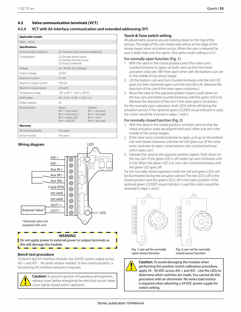
WARNINGDo not apply power to external power to output terminals as this will damage the module.
4.5 Valve communication terminals (VCT)
4.5.4 VCT with AS-Interface communication and extended addressing (97)
Applicable models
QN97_, QX97_
Specifications
Communication protocol AS- Interface with extended addressing
Configuration (2) Discrete sensor Inputs(2) Auxiliary Discrete Inputs(1) Output (solenoid)
Voltage 24 - 30 VDC (AS-i Voltage)
Output voltage 24 VDC
Quiescent current 21 mA
Maximum output current 100 mA
Maximum output power 2.4 watts
Temperature range -40° to 82° C (-40° to 180° F)
ID/IO codes ID = A; IO = 4; ID1 = 7; ID2 = E
Default address 0A
Bit assignment InputsBit 1 = Aux input 1Bit 2 = Aux input 2Bit 3 = green LEDBit 4 = red LED
OutputsBit 1 = not usedBit 2 = not usedBit 3 = OUT 1Bit 4 = not used
Warranty
All mechanical parts Two years
Sensor module Five years
Touch & Tune switch settingAll adjustments assume you are looking down on the top of the sensors. The edge of the cam metal strip will be at the edge of the sensor target when activation occurs. When the cam is released be sure it slides fully onto the spline. One spline tooth setting is 4 1/2°.
For normally open function (Fig. 1)1. With the valve in the closed position and if the valve turns
counterclockwise to open, set both cams so that the metal activation strips are 180° from each other with the bottom cam set in the middle of the sensor target.
2. Lift the bottom cam and turn counterclockwise until the red LED goes out then clockwise again until the red LED is lit. (Reverse the direction of the cam if the valve opens clockwise.)
3. Move the valve to the opposite position (open), push down on the top cam and rotate counterclockwise until the green LED is lit. (Reverse the direction of the cam if the valve opens clockwise.)
For the normally open operation, both LEDs will be off during the actuation period. If the optional green CLOSED visual indicator is used, the colors would be reversed in steps 1 and 2.
For normally closed function (Fig. 2)1. With the valve in the closed position, set both cams so that the
metal activation strips are aligned with each other and set in the middle of the sensor targets.
2. If the valve turns counterclockwise to open, pull up on the bottom cam and rotate clockwise until the red LED goes out. (If the valve turns clockwise to open, rotate bottom cam counterclockwise until it goes out.)
3. Operate the valve to the opposite position (open). Push down on the top cam. If the green LED is off, rotate top cam clockwise until it is lit. When the green LED is lit, turn cam counterclockwise until the green LED goes off.
For the normally closed operation, both the red and green LEDs will be illuminated during the actuation period. The red LED is off in the closed position and the green LED is off in the open position. If the optional green CLOSED visual indicator is used the colors would be reversed in steps 1 and 2.
Caution: To avoid damaging the module when performing the position switch calibration procedure, apply 24 - 30 VDC across ASI + and ASI -. Use the LEDs to determine when switches are made. You cannot do this procedure with an ohmmeter. No series load resistor is required when attaching a 24 VDC power supply for switch setting.
ASI +
LED
LED
ASI -
Aux IN +
Aux IN1 -
Aux IN2 -
3 wire RTN
not used
not used
OUT1 +
OUT1 -Solenoid Valve*
*Solenoid valve notsupplied with unit
Wiring diagram
Caution: To prevent ignition of hazardous atmospheres, replace cover before energizing the electrical circuits. Keep cover tightly closed within operation.
Fig. 1 cam set for normally open sensor function
Fig. 2 cam set for normally closed sensor functionBench test procedure
To bench test AS-Interface module: Use 24 VDC power supply across ASI + and ASI -. No series resistor needed. To test communication, a functioning AS-Interface network is required.
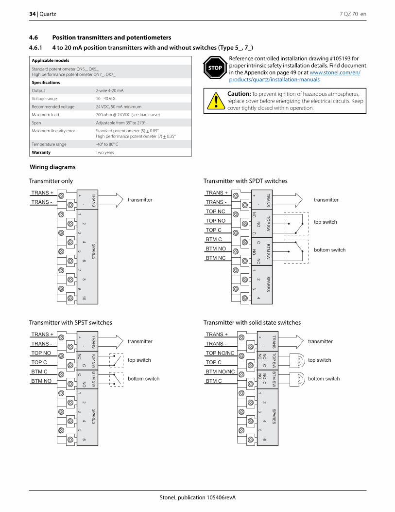
7 QZ 70 en34 | Quartz
StoneL publication 105406revA
4.6 Position transmitters and potentiometers
4.6.1 4 to 20 mA position transmitters with and without switches (Type 5_, 7_)
Applicable models
Standard potentiometer QN5_, QX5_High performance potentiometer QN7_, QX7_
Specifications
Output 2-wire 4-20 mA
Voltage range 10 - 40 VDC
Recommended voltage 24 VDC, 50 mA minimum
Maximum load 700 ohm @ 24 VDC (see load curve)
Span Adjustable from 35° to 270°
Maximum linearity error Standard potentiometer (5) + 0.85°High performance potentiometer (7) + 0.35°
Temperature range -40° to 80° C
Warranty Two years
Wiring diagrams
Transmitter with SPST switches
Transmitter only Transmitter with SPDT switches
transmitter
top switch
bottom switch
TRANS +
TRANS -
TOP NO
TOP C
BTM C
BTM NO
SPA
RE
S
CN
O1
23
45
6
TOP S
WB
TM S
WTR
AN
S
CN
O-
+
transmitterTRANS +
TRANS -
SPA
RE
S
34
56
78
910
TRA
NS
21
-+
transmitter
top switch
bottom switch
TRANS +
TRANS -
TOP NC
TOP NO
TOP C
BTM C
BTM NO
BTM NC
SPA
RE
S
CC
NO
NC
12
34
TOP S
WB
TM S
WTR
AN
S
NO
NC
-+
Transmitter with solid state switches
transmitter
top switch
bottom switch
TRANS +
TRANS -
TOP NO/NC
TOP C
BTM NO/NC
BTM C
SPA
RE
S
NO
NC
C1
23
45
6
TOP S
WB
TM S
WTR
AN
S
CN
ON
C-
+
Caution: To prevent ignition of hazardous atmospheres, replace cover before energizing the electrical circuits. Keep cover tightly closed within operation.
Reference controlled installation drawing #105193 for proper intrinsic safety installation details. Find document in the Appendix on page 49 or at www.stonel.com/en/products/quartz/installation-manuals
STOP
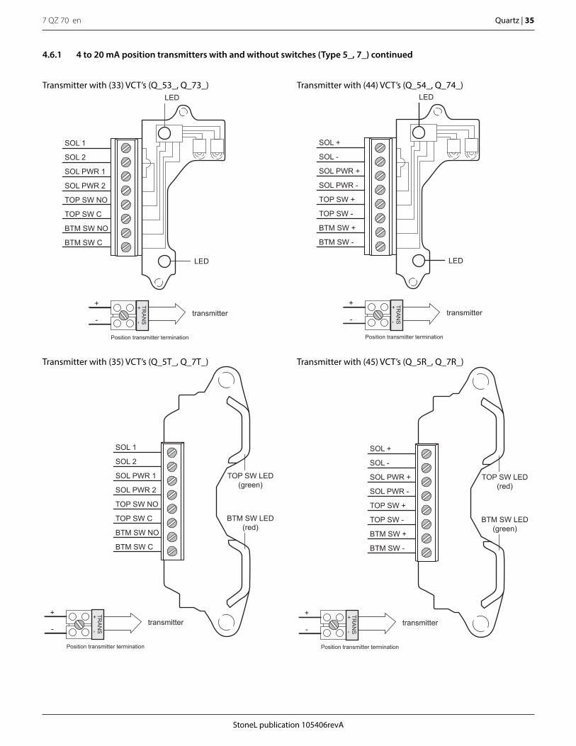
StoneL publication 105406revA
7 QZ 70 en Quartz | 35
Transmitter with (33) VCT’s (Q_53_, Q_73_)
Transmitter with (35) VCT’s (Q_5T_, Q_7T_)
-+
LED
LED
SOL 1
SOL 2
SOL PWR 1
SOL PWR 2
TOP SW NO
TOP SW C
BTM SW NO
BTM SW C
Position transmitter termination
TRA
NS
+
-transmitter
TOP SW LED(red)
BTM SW LED(green)
SOL +
SOL -
SOL PWR +
SOL PWR -
TOP SW +
TOP SW -
BTM SW +
BTM SW -
-+
Position transmitter termination
TRA
NS
+
-transmitter
TOP SW LED(green)
BTM SW LED(red)
SOL 1
SOL 2
SOL PWR 1
SOL PWR 2
TOP SW NO
TOP SW C
BTM SW NO
BTM SW C
-+
Position transmitter termination
TRA
NS
+
-transmitter
Transmitter with (45) VCT’s (Q_5R_, Q_7R_)
Transmitter with (44) VCT’s (Q_54_, Q_74_)LED
LED
SOL +
SOL -
SOL PWR +
SOL PWR -
TOP SW +
TOP SW -
BTM SW +
BTM SW -
-+
Position transmitter termination
TRA
NS
+
-transmitter
4.6.1 4 to 20 mA position transmitters with and without switches (Type 5_, 7_) continued
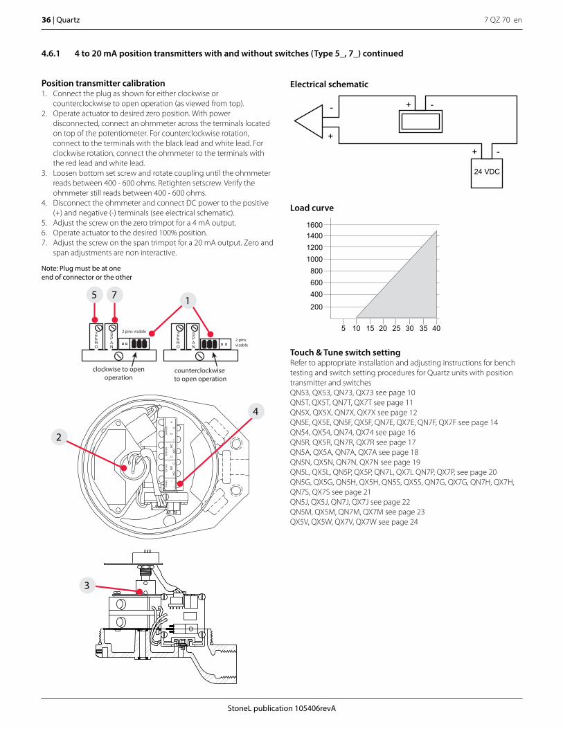
7 QZ 70 en36 | Quartz
StoneL publication 105406revA
5 10 15 20 25 30 35 40
200
400600800
1000120014001600
Position transmitter calibration1. Connect the plug as shown for either clockwise or
counterclockwise to open operation (as viewed from top).2. Operate actuator to desired zero position. With power
disconnected, connect an ohmmeter across the terminals located on top of the potentiometer. For counterclockwise rotation, connect to the terminals with the black lead and white lead. For clockwise rotation, connect the ohmmeter to the terminals with the red lead and white lead.
3. Loosen bottom set screw and rotate coupling until the ohmmeter reads between 400 - 600 ohms. Retighten setscrew. Verify the ohmmeter still reads between 400 - 600 ohms.
4. Disconnect the ohmmeter and connect DC power to the positive (+) and negative (-) terminals (see electrical schematic).
5. Adjust the screw on the zero trimpot for a 4 mA output.6. Operate actuator to the desired 100% position.7. Adjust the screw on the span trimpot for a 20 mA output. Zero and
span adjustments are non interactive.
Load curve
4.6.1 4 to 20 mA position transmitters with and without switches (Type 5_, 7_) continued
Electrical schematic
SPA
RE
S
CC
NO
NC
12
34
TOP
SW
BTM
SW
TRA
NS
NO
NC
-+
ZERO
SPAN
ZERO
SPAN
clockwise to openoperation
2 pins visable
2 pins visable
counterclockwise to open operation
3
75 1
2
4
Note: Plug must be at one end of connector or the other
+ -
+ -
+
-
24 VDC
Touch & Tune switch settingRefer to appropriate installation and adjusting instructions for bench testing and switch setting procedures for Quartz units with position transmitter and switchesQN53, QX53, QN73, QX73 see page 10QN5T, QX5T, QN7T, QX7T see page 11QN5X, QX5X, QN7X, QX7X see page 12QN5E, QX5E, QN5F, QX5F, QN7E, QX7E, QN7F, QX7F see page 14QN54, QX54, QN74, QX74 see page 16QN5R, QX5R, QN7R, QX7R see page 17QN5A, QX5A, QN7A, QX7A see page 18QN5N, QX5N, QN7N, QX7N see page 19QN5L, QX5L, QN5P, QX5P, QN7L, QX7L QN7P, QX7P, see page 20QN5G, QX5G, QN5H, QX5H, QN5S, QX5S, QN7G, QX7G, QN7H, QX7H, QN7S, QX7S see page 21QN5J, QX5J, QN7J, QX7J see page 22QN5M, QX5M, QN7M, QX7M see page 23QX5V, QX5W, QX7V, QX7W see page 24
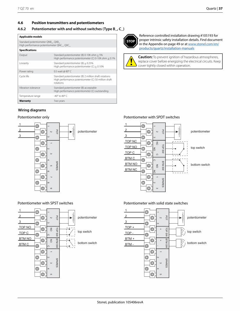
StoneL publication 105406revA
7 QZ 70 en Quartz | 37
4.6 Position transmitters and potentiometers
4.6.2 Potentiometer with and without switches (Type B_, C_)
Applicable models
Standard potentiometer QNB_, QXB_High performance potentiometer QNC_, QXC_
Specifications
Output Standard potentiometer (B) 0-10K ohm + 5%High performance potentiometer (C) 0-10K ohm + 0.1%
Linearity Standard potentiometer (B) + 0.25%High performance potentiometer (C) + 0.10%
Power rating 0.5 watt @ 80° C
Cycle life Standard potentiometer (B) 2 million shaft rotationsHigh performance potentiometer (C) 50 million shaft rotations
Vibration tolerance Standard potentiometer (B) acceptableHigh performance potentiometer (C) outstanding
Temperature range -40° to 80° C
Warranty Two years
Wiring diagrams
Potentiometer only
potentiometer
1
2
3
SPA
RE
S
23
45
67
89
PO
T
13
21
Potentiometer with SPST switches
potentiometer
top switch
bottom switch
1
2
3
TOP NO
TOP C
BTM NO
BTM C
SPA
RE
S
CN
OC
12
34
5
TOP S
WB
TM S
WP
OT
NO
32
1
Potentiometer with SPDT switches
potentiometer
top switch
bottom switch
1
3
2
TOP NC
TOP NO
TOP C
BTM C
BTM NO
BTM NC
SPA
RE
S
NO
CC
NO
NC
12
3
TOP S
WB
TM S
WP
OT
NC
32
1
Potentiometer with solid state switches
potentiometer
top switch
bottom switch
1
3
2
TOP +
TOP -
BTM +
BTM -
SPA
RE
S
+-
12
34
5
TOP S
WB
TM S
WP
OT
+2
13
-
Caution: To prevent ignition of hazardous atmospheres, replace cover before energizing the electrical circuits. Keep cover tightly closed within operation.
Reference controlled installation drawing #105193 for proper intrinsic safety installation details. Find document in the Appendix on page 49 or at www.stonel.com/en/products/quartz/installation-manuals
STOP

7 QZ 70 en38 | Quartz
StoneL publication 105406revA
Potentiometer with (33) VCT’s (Q_B3_, Q_C3_)
Potentiometer with (35) VCT’s (Q_BT_, Q_CT_)
LED
LED
SOL 1
SOL 2
SOL PWR 1
SOL PWR 2
TOP SW NO
TOP SW C
BTM SW NO
BTM SW C
1
2
3
potentiometer
PO
T2
31
Potentiometer termination
TOP SW LED(red)
BTM SW LED(green)
SOL +
SOL -
SOL PWR +
SOL PWR -
TOP SW +
TOP SW -
BTM SW +
BTM SW -
Potentiometer termination
1
2
3
potentiometer
PO
T2
31
TOP SW LED(green)
BTM SW LED(red)
SOL 1
SOL 2
SOL PWR 1
SOL PWR 2
TOP SW NO
TOP SW C
BTM SW NO
BTM SW C
Potentiometer termination
1
2
3
potentiometer
PO
T2
31
Potentiometer with (44) VCT’s (Q_B4_, Q_C4_)
Potentiometer with (45) VCT’s (Q_BR_, Q_CR_)
LED
LED
SOL +
SOL -
SOL PWR +
SOL PWR -
TOP SW +
TOP SW -
BTM SW +
BTM SW -
Potentiometer termination
1
2
3
potentiometer
PO
T2
31
4.6.2 Potentiometer with and without switches (Type B_, C_) continued
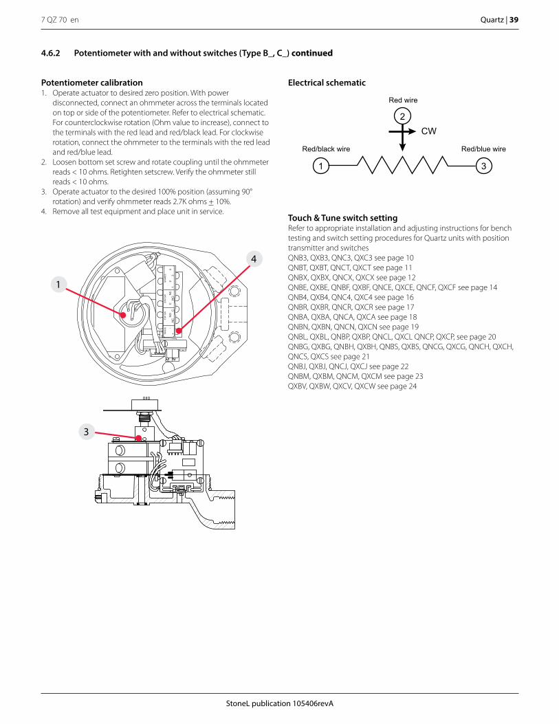
StoneL publication 105406revA
7 QZ 70 en Quartz | 39
2
1 3
CW
Red/black wire Red/blue wire
Red wire
SPA
RE
S
CC
NO
NC
12
34
TOP
SW
BTM
SW
TRA
NS
NO
NC
-+
Potentiometer calibration1. Operate actuator to desired zero position. With power
disconnected, connect an ohmmeter across the terminals located on top or side of the potentiometer. Refer to electrical schematic. For counterclockwise rotation (Ohm value to increase), connect to the terminals with the red lead and red/black lead. For clockwise rotation, connect the ohmmeter to the terminals with the red lead and red/blue lead.
2. Loosen bottom set screw and rotate coupling until the ohmmeter reads < 10 ohms. Retighten setscrew. Verify the ohmmeter still reads < 10 ohms.
3. Operate actuator to the desired 100% position (assuming 90° rotation) and verify ohmmeter reads 2.7K ohms + 10%.
4. Remove all test equipment and place unit in service.
4.6.2 Potentiometer with and without switches (Type B_, C_) continued
3
1
4
Electrical schematic
Touch & Tune switch settingRefer to appropriate installation and adjusting instructions for bench testing and switch setting procedures for Quartz units with position transmitter and switchesQNB3, QXB3, QNC3, QXC3 see page 10QNBT, QXBT, QNCT, QXCT see page 11QNBX, QXBX, QNCX, QXCX see page 12QNBE, QXBE, QNBF, QXBF, QNCE, QXCE, QNCF, QXCF see page 14QNB4, QXB4, QNC4, QXC4 see page 16QNBR, QXBR, QNCR, QXCR see page 17QNBA, QXBA, QNCA, QXCA see page 18QNBN, QXBN, QNCN, QXCN see page 19QNBL, QXBL, QNBP, QXBP, QNCL, QXCL QNCP, QXCP, see page 20QNBG, QXBG, QNBH, QXBH, QNBS, QXBS, QNCG, QXCG, QNCH, QXCH, QNCS, QXCS see page 21QNBJ, QXBJ, QNCJ, QXCJ see page 22QNBM, QXBM, QNCM, QXCM see page 23QXBV, QXBW, QXCV, QXCW see page 24
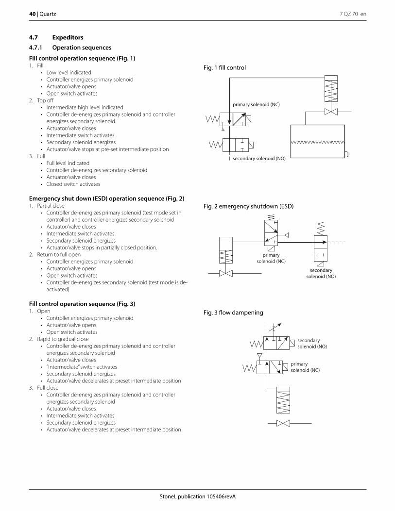
7 QZ 70 en40 | Quartz
StoneL publication 105406revA
4.7 Expeditors
4.7.1 Operation sequences
Fill control operation sequence (Fig. 1)1. Fill
• Low level indicated• Controller energizes primary solenoid• Actuator/valve opens• Open switch activates
2. Top off• Intermediate high level indicated• Controller de-energizes primary solenoid and controller
energizes secondary solenoid• Actuator/valve closes• Intermediate switch activates• Secondary solenoid energizes• Actuator/valve stops at pre-set intermediate position
3. Full• Full level indicated• Controller de-energizes secondary solenoid• Actuator/valve closes• Closed switch activates
Emergency shut down (ESD) operation sequence (Fig. 2)1. Partial close
• Controller de-energizes primary solenoid (test mode set in controller) and controller energizes secondary solenoid
• Actuator/valve closes• Intermediate switch activates• Secondary solenoid energizes• Actuator/valve stops in partially closed position.
2. Return to full open• Controller energizes primary solenoid• Actuator/valve opens• Open switch activates• Controller de-energizes secondary solenoid (test mode is de-
activated)
Fill control operation sequence (Fig. 3)1. Open
• Controller energizes primary solenoid• Actuator/valve opens• Open switch activates
2. Rapid to gradual close• Controller de-energizes primary solenoid and controller
energizes secondary solenoid• Actuator/valve closes• ”Intermediate” switch activates• Secondary solenoid energizes• Actuator/valve decelerates at preset intermediate position
3. Full close• Controller de-energizes primary solenoid and controller
energizes secondary solenoid• Actuator/valve closes• Intermediate switch activates• Secondary solenoid energizes• Actuator/valve decelerates at preset intermediate position
primarysolenoid (NC)
secondarysolenoid (NO)
primary solenoid (NC)
secondary solenoid (NO)
primarysolenoid (NC)
secondarysolenoid (NO)
Fig. 1 fill control
Fig. 2 emergency shutdown (ESD)
Fig. 3 flow dampening

StoneL publication 105406revA
7 QZ 70 en Quartz | 41
Applicable models
QX8V_, QX8W_
Expeditor with SPDT mechanical switches with silver contacts (QX8V_)*
Electrical ratings 10.0 amp @ 125/250 VAC0.5 amp @ 125 VDC
Temperature range -40° to 80° C
Operating life 400,000 cycles
Warranty Two years
* Not recommended for electrical circuits operating at less than 20 mA @ 24 VDC
Expeditor with SPDT mechanical switches with gold contacts (QX8W_)**
Electrical ratings 1.0 amp @ 125 VAC0.5 amp @ 30 VDC
Temperature range -40° to 80° C
Operating life 100,000 cycles
Warranty Two years
** Recommended for use in 24 VDC computer input applications
4.7 Expeditors
4.7.2 With mechanical switches (8V, 8W)
Touch & Tune switch settingAll adjustments assume you are looking down on the top of the sensors. The edge of the cam metal strip will be at the edge of the sensor target when activation occurs. When the cam is released be sure it slides fully onto the spline. One spline tooth setting is 4 1/2°.1. At full open position depress middle cam and rotate until switch is
activated. Release cam and be sure it slides fully onto spline.2. At full closed position lift bottom cam and rotate until switch is
activated. Release cam and be sure it slides fully onto spline.
Caution: To prevent ignition of hazardous atmospheres, replace cover before energizing the electrical circuits. Keep cover tightly closed within operation.
Intermediate switch settingAt full closed position lift top cam and rotate in clockwise direction past 0° to desired degree setting for intermediate switch to be energized. After setting is made, run actuator to full open position. De-energize primary solenoid and observe valve position after intermediate switch is activated and secondary solenoid is energized. Readjust top cam if necessary to increase or decrease angle of valve when intermediate switch is activated.
Wiring diagram
180°
90°
15°
75°
30°45° 60°90°
0°
60°
75°
30°
45°
15°
Intermediate switch
closed switch
open switch
SECOND 4
CLOSED C
CLOSED NC
CLOSED NO
SECOND 3
OPEN NO
OPEN NC
INTERMEDIATE NO
INTERMEDIATE C
OPEN C
PRIMARY 2
PRIMARY 1
INTE
R-
ME
DIATE
OP
EN
12
34
SO
LEN
OID
NC
PR
IMA
RY
NO
SE
CO
ND
CN
CN
OC
NO
C
CLO
SE
D
*Solenoids not supplied with unit
intermediate switch
primary solenoid*
secondary solenoid*
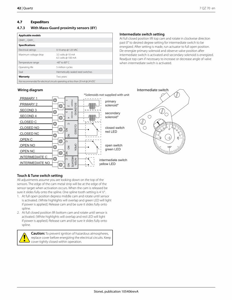
7 QZ 70 en42 | Quartz
StoneL publication 105406revA
Applicable models
QN8Y_, QX8Y_
Specifications
Electrical ratings 0.10 amp @ 125 VAC
Maximum voltage drop 3.5 volts @ 10 mA6.5 volts @ 100 mA
Temperature range -40° to 80° C
Operating life 5 million cycles
Seal Hermetically sealed reed switches
Warranty Two years
Not recommended for electrical circuits operating at less than 20 mA @ 24 VDC
4.7 Expeditors
4.7.3 With Maxx-Guard proximity sensors (8Y)
Touch & Tune switch settingAll adjustments assume you are looking down on the top of the sensors. The edge of the cam metal strip will be at the edge of the sensor target when activation occurs. When the cam is released be sure it slides fully onto the spline. One spline tooth setting is 4 1/2°.1. At full open position depress middle cam and rotate until sensor
is activated. (White highlights will overlap and green LED will light if power is applied.) Release cam and be sure it slides fully onto spline.
2. At full closed position lift bottom cam and rotate until sensor is activated. (White highlights will overlap and red LED will light if power is applied.) Release cam and be sure it slides fully onto spline.
Caution: To prevent ignition of hazardous atmospheres, replace cover before energizing the electrical circuits. Keep cover tightly closed within operation.
Intermediate switch settingAt full closed position lift top cam and rotate in clockwise direction past 0° to desired degree setting for intermediate switch to be energized. After setting is made, run actuator to full open position. De-energize primary solenoid and observe valve position after intermediate switch is activated and secondary solenoid is energized. Readjust top cam if necessary to increase or decrease angle of valve when intermediate switch is activated.
Wiring diagram
closed switchred LED
open switchgreen LED
SECOND 4
CLOSED C
CLOSED NC
CLOSED NO
SECOND 3
OPEN NO
OPEN NC
INTERMEDIATE NO
INTERMEDIATE C
OPEN C
PRIMARY 2
PRIMARY 1
INTE
R-
ME
DIATE
OP
EN
12
34
SO
LEN
OID
NC
PR
IMA
RY
NO
SE
CO
ND
CN
CN
OC
NO
C
CLO
SE
D
*Solenoids not supplied with unit
intermediate switchyellow LED
primary solenoid*
secondary solenoid*
180°
90°
15°
75°
30°45° 60°90°
0°
60°
75°
30°
45°
15°
Intermediate switch
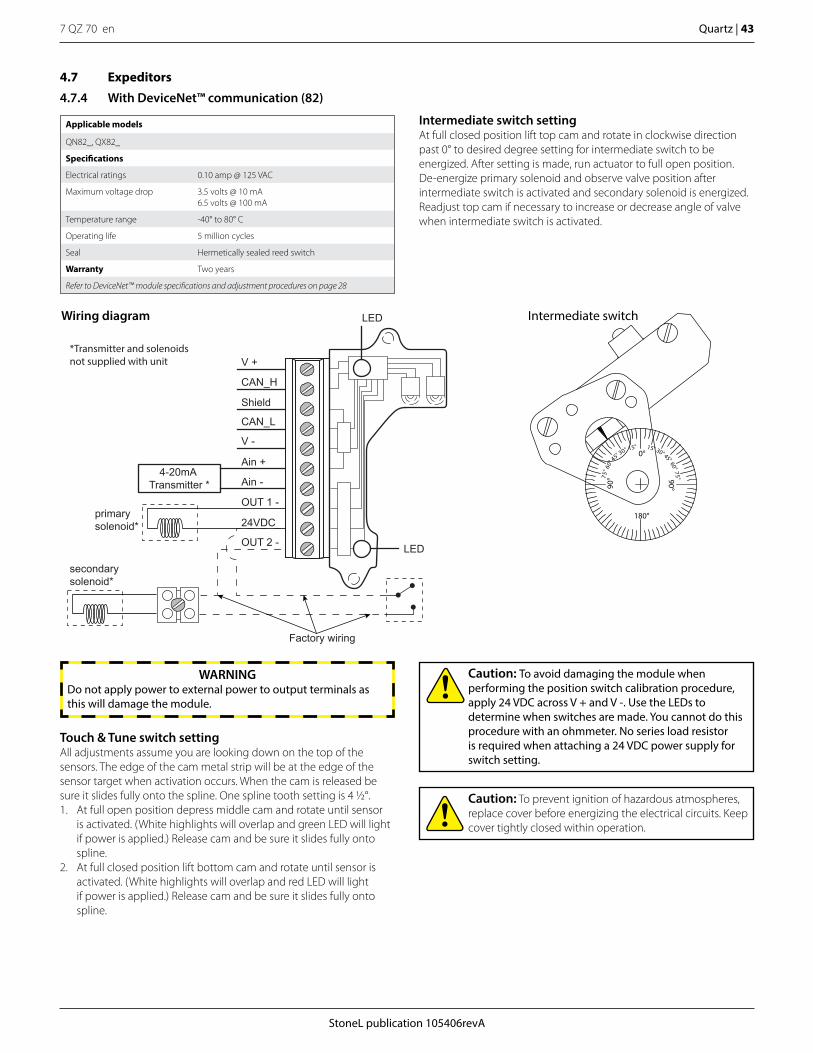
StoneL publication 105406revA
7 QZ 70 en Quartz | 43
Touch & Tune switch settingAll adjustments assume you are looking down on the top of the sensors. The edge of the cam metal strip will be at the edge of the sensor target when activation occurs. When the cam is released be sure it slides fully onto the spline. One spline tooth setting is 4 1/2°.1. At full open position depress middle cam and rotate until sensor
is activated. (White highlights will overlap and green LED will light if power is applied.) Release cam and be sure it slides fully onto spline.
2. At full closed position lift bottom cam and rotate until sensor is activated. (White highlights will overlap and red LED will light if power is applied.) Release cam and be sure it slides fully onto spline.
Applicable models
QN82_, QX82_
Specifications
Electrical ratings 0.10 amp @ 125 VAC
Maximum voltage drop 3.5 volts @ 10 mA6.5 volts @ 100 mA
Temperature range -40° to 80° C
Operating life 5 million cycles
Seal Hermetically sealed reed switch
Warranty Two years
Refer to DeviceNet™ module specifications and adjustment procedures on page 28
4.7 Expeditors
4.7.4 With DeviceNet™ communication (82)
Caution: To avoid damaging the module when performing the position switch calibration procedure, apply 24 VDC across V + and V -. Use the LEDs to determine when switches are made. You cannot do this procedure with an ohmmeter. No series load resistor is required when attaching a 24 VDC power supply for switch setting.
Caution: To prevent ignition of hazardous atmospheres, replace cover before energizing the electrical circuits. Keep cover tightly closed within operation.
Intermediate switch settingAt full closed position lift top cam and rotate in clockwise direction past 0° to desired degree setting for intermediate switch to be energized. After setting is made, run actuator to full open position. De-energize primary solenoid and observe valve position after intermediate switch is activated and secondary solenoid is energized. Readjust top cam if necessary to increase or decrease angle of valve when intermediate switch is activated.
WARNINGDo not apply power to external power to output terminals as this will damage the module.
Wiring diagram
180°
90°
15°
75°
30°45° 60°90°
0°
60°
75°
30°
45°
15°
Intermediate switch
V +
LED
LED
CAN_H
Shield
CAN_L
V -
Ain +
Ain -
OUT 1 -
24VDC
OUT 2 -
4-20mA Transmitter *
*Transmitter and solenoids not supplied with unit
Factory wiring
primary solenoid*
secondary solenoid*
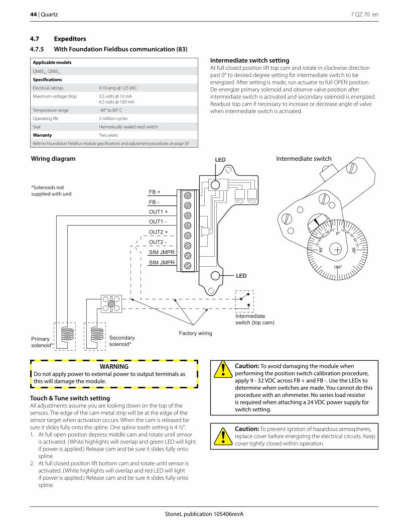
7 QZ 70 en44 | Quartz
StoneL publication 105406revA
Applicable models
QN83_, QX83_
Specifications
Electrical ratings 0.10 amp @ 125 VAC
Maximum voltage drop 3.5 volts @ 10 mA6.5 volts @ 100 mA
Temperature range -40° to 80° C
Operating life 5 million cycles
Seal Hermetically sealed reed switch
Warranty Two years
Refer to Foundation Fieldbus module specifications and adjustment procedures on page 30
4.7 Expeditors
4.7.5 With Foundation Fieldbus communication (83)
Caution: To avoid damaging the module when performing the position switch calibration procedure, apply 9 - 32 VDC across FB + and FB -. Use the LEDs to determine when switches are made. You cannot do this procedure with an ohmmeter. No series load resistor is required when attaching a 24 VDC power supply for switch setting.
Caution: To prevent ignition of hazardous atmospheres, replace cover before energizing the electrical circuits. Keep cover tightly closed within operation.
Intermediate switch settingAt full closed position lift top cam and rotate in clockwise direction past 0° to desired degree setting for intermediate switch to be energized. After setting is made, run actuator to full OPEN position. De-energize primary solenoid and observe valve position after intermediate switch is activated and secondary solenoid is energized. Readjust top cam if necessary to increase or decrease angle of valve when intermediate switch is activated.
Touch & Tune switch settingAll adjustments assume you are looking down on the top of the sensors. The edge of the cam metal strip will be at the edge of the sensor target when activation occurs. When the cam is released be sure it slides fully onto the spline. One spline tooth setting is 4 1/2°.1. At full open position depress middle cam and rotate until sensor
is activated. (White highlights will overlap and green LED will light if power is applied.) Release cam and be sure it slides fully onto spline.
2. At full closed position lift bottom cam and rotate until sensor is activated. (White highlights will overlap and red LED will light if power is applied.) Release cam and be sure it slides fully onto spline.
WARNINGDo not apply power to external power to output terminals as this will damage the module.
Wiring diagram
180°
90°
15°
75°
30°45° 60°90°
0°
60°
75°
30°
45°
15°
Intermediate switchLED
LED
*Solenoids not supplied with unit
Primarysolenoid*
Secondarysolenoid*
Factory wiring
Intermediate switch (top cam)
LED
LED
FB +
FB -
OUT1 +
OUT1 -
OUT2 +
OUT2 -
SIM JMPR
SIM JMPR
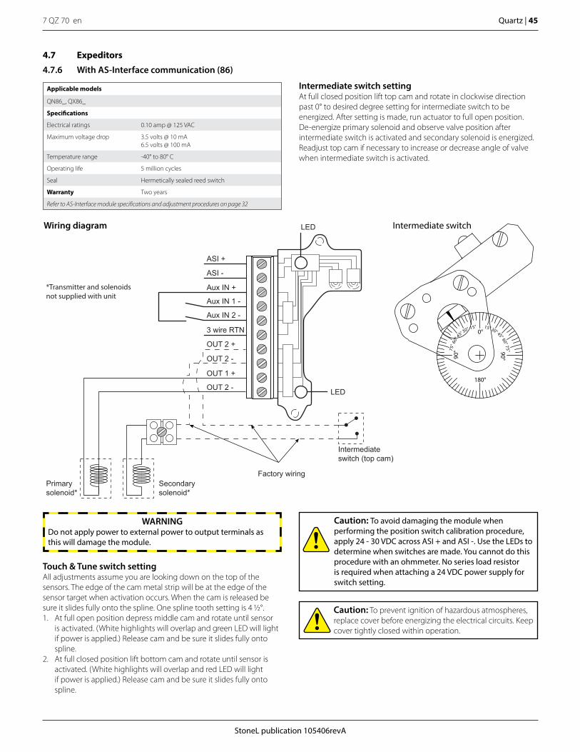
StoneL publication 105406revA
7 QZ 70 en Quartz | 45
Applicable models
QN86_, QX86_
Specifications
Electrical ratings 0.10 amp @ 125 VAC
Maximum voltage drop 3.5 volts @ 10 mA6.5 volts @ 100 mA
Temperature range -40° to 80° C
Operating life 5 million cycles
Seal Hermetically sealed reed switch
Warranty Two years
Refer to AS-Interface module specifications and adjustment procedures on page 32
4.7 Expeditors
4.7.6 With AS-Interface communication (86)
Caution: To avoid damaging the module when performing the position switch calibration procedure, apply 24 - 30 VDC across ASI + and ASI -. Use the LEDs to determine when switches are made. You cannot do this procedure with an ohmmeter. No series load resistor is required when attaching a 24 VDC power supply for switch setting.
Caution: To prevent ignition of hazardous atmospheres, replace cover before energizing the electrical circuits. Keep cover tightly closed within operation.
Intermediate switch settingAt full closed position lift top cam and rotate in clockwise direction past 0° to desired degree setting for intermediate switch to be energized. After setting is made, run actuator to full open position. De-energize primary solenoid and observe valve position after intermediate switch is activated and secondary solenoid is energized. Readjust top cam if necessary to increase or decrease angle of valve when intermediate switch is activated.
Touch & Tune switch settingAll adjustments assume you are looking down on the top of the sensors. The edge of the cam metal strip will be at the edge of the sensor target when activation occurs. When the cam is released be sure it slides fully onto the spline. One spline tooth setting is 4 1/2°.1. At full open position depress middle cam and rotate until sensor
is activated. (White highlights will overlap and green LED will light if power is applied.) Release cam and be sure it slides fully onto spline.
2. At full closed position lift bottom cam and rotate until sensor is activated. (White highlights will overlap and red LED will light if power is applied.) Release cam and be sure it slides fully onto spline.
WARNINGDo not apply power to external power to output terminals as this will damage the module.
180°
90°
15°
75°
30°45° 60°90°
0°
60°
75°
30°
45°
15°
Intermediate switchWiring diagram LED
LED
*Transmitter and solenoids not supplied with unit
Factory wiring
Intermediate switch (top cam)
ASI +
ASI -
Aux IN +
Aux IN 1 -
Aux IN 2 -
3 wire RTN
OUT 2 +
OUT 2 -
OUT 1 +
OUT 2 -
Primary solenoid*
Secondary solenoid*
7 QZ 70 en46 | Quartz
StoneL publication 105406revA
5 Model/Type code
5.1 QGabcdefa = 2W, 4W, 6W, 2V, 4V, 6V, 14b = C or Pc = 02, 03, 05, 06d = S, N, He = A, C, D, G, N, R, S, T, U, V, W, X, 1, 2, 3, 4, 5, 0f = A or M
5.2 QNabcdefa = 2A, 4A, 5A, 7A, 2E, 4E, 5E, 7E, 2F, 4F, 5F, 7F, 2G, 4G, 5G, 7G, 2H, 4H, 5H, 7H, 8H, 2J, 4J, 5J, 7J, 2L, 4L, 5L, 7L, 2M, 4M, 5M, 7M, 2N, 4N, 5N, 6N, 7N, 5O, 7O, 2P, 4P, 5P, 7P, 5R, 7R, 2S, 4S, 5S, 7S, 5T, 7T, 2X, 4X, 5X, 6X, 7X, 8Y, 33, 35, 44, 45, 53, 54, 73, 74, 82, 83, 84, 86, 87, 92, 93, 94, 96, 97, 98, B3, C3, B4, C4, BA, CA, BE, CE, BF, CF, BG, CG, BH, CH, BJ, CJ, BL, CL, BM, CM, BN, CN, BO, CO, BP, CP, BR, CR, BS, CS, BT, CT, BX, CXb = A, B, C, D, E, F, G, J, M, N, P, Q, R, S, T, U, W, Y, Zc = 02, 03, 05, 06d = S, N, He = A, C, D, G, N, R, S, T, U, V, W, X, 1, 2, 3, 4, 5, 0f = A or M
5.3 QXabcdefa = 2A, 4A, 5A, 7A, 2E, 4E, 5E, 7E, 2F, 4F, 5F, 7F, 2G, 4G, 5G, 7G, 2H, 4H, 5H, 7H, 8H, 2J, 4J, 5J, 7J, 2L, 4L, 5L, 7L, 2M, 4M, 5M, 7M, 2N, 4N, 5N, 6N, 7N, 5O, 7O, 2P, 4P, 5P, 7P, 5R, 7R, 2S, 4S, 5S, 7S, 5T, 7T, 2V, 4V, 5V, 6V, 7V, 8V, 2W, 4W, 5W, 6W, 7W, 8W, 2X, 4X, 5X, 6X, 7X, 8Y, 14, 33, 35, 44, 45, 53, 54, 73, 74, 82, 83, 84, 86, 87, 92, 93, 94, 96, 97, 98, B3, C3, B4, C4, BA, CA, BE, CE, BF, CF, BG, CG, BH, CH, BJ, CJ, BL, CL, BM, CM, BN, CN, BO, CO, BP, CP, BR, CR, BS, CS, BT, CT, BV, CV, BW, CW, BX, CXb = B, E, F, G, J, M, N, R, S, T, Wc = 02, 03, 05, 06d = S, N, He = A, C, D, G, N, R, S, T, U, V, W, X, 1, 2, 3, 4, 5, 0f = A or M
StoneL publication 105406revA
7 QZ 70 en Quartz | 47
105414revA
DECLARATION OF CONFORMITY Manufacturer: Metso Flow Control, USA Inc. dba StoneL 26271 US Highway 59 Fergus Falls, Minnesota 56537 USA Products: Quartz QN Series – Valve Position Monitors and Valve Communication Terminals Quartz QX Series – Valve Position Monitors and Valve Communication Terminals Quartz QG Series – Valve Position Monitors and Valve Communication Terminals Model - Type Certificates / Directives / Standards Marking QN Series QX Series
EU Type Examination Certificate FM10ATEX0039X ATEX 2014/34/EU EN 60079-0:2012+A11:2013, EN 60079-11:2012 EMC 2014/30/EU EN 60947-5-2:2007/A1:2012
ATEX II 1 G Ex ia IIC T6…T1 Ga
QX Series EU Type Examination Certificate FM08ATEX0008X ATEX 2014/34/EU EN 60079-0:2012+A11:2013, EN 60079-1:2014 EMC 2014/30/EU EN 60947-5-2:2007/A1:2012
ATEX II 2 G c Ex db IIC T6…T5 Gb
QX Series
IECEx Certificate of Conformity IECEx FMG 11.0001X IEC 60079-0:2011, IEC 60079-1:2014
Ex db IIC T6…T5 Gb
QN Series QX Series QG Series
EMC 2014/30/EU EN 60947-5-2:2007/A1:2012
ATEX Notified Bodies for EU Type Examination Certificates: FM Approvals Ltd. Windsor, Berkshire, UK (Notified Body Number 1725) Manufacturing Locations: 26271 US Hwy 59, Fergus Falls, Minnesota 56537 USA
Product Serial Number Designation = A****** Quality Assurance Certificates: ISO 9001:2008…………………………...TUV SUD America Inc. QAN FM06ATEXQ0013………………….FM Approvals (Notified Body Number 1725) QAR GB/FME/QAR11.0003……….…….FM Approvals (Notified Body Number 1725)
Vanha Porvoontie 229, FIN-01380 Vantaa, Finland
Product Serial Number Designation = V****** Quality Assurance Certificates: ISO 9001:2015…………………………...DNV (Notified Body Number 0575) QAN DNV-2006-OSL-ATEX-0260Q….…DNV (Notified Body Number 0575) QAR NO/DNV/QAR09.0008…………….DNV (Notified Body Number 0575)
261 Meiyue Rd, Waigaoqiao Free Trade Zone, 200131 Shanghai, China Product Serial Number Designation = S****** Quality Assurance Certificates: ISO 9001:2015…………………………...DNV (Notified Body Number 0575) QAN DNV-2006-OSL-ATEX-0260Q….…DNV (Notified Body Number 0575) QAR NO/DNV/QAR09.0008…………….DNV (Notified Body Number 0575)
We declare under our sole responsibility that the products, as described, are in conformity with the listed standards and directives.
Fergus Falls, 1st June 2017
Bryan Beckman, Quality Manager Authorized Person of the Manufacturer
6 Regulatory, specific conditions of use, and product marking
7 QZ 70 en48 | Quartz
StoneL publication 105406revA
105414revA
SPECIFIC CONDITIONS OF USE / MARKING
For QN and QX Series -- FM10ATEX0039X Specific Conditions of Use - Notes Marking 1. Parts of the enclosure are non-conducting and may generate an ignition-capable level of electrostatic charge under certain extreme conditions. The user should ensure that the equipment is not installed in a location where it may be subjected to external conditions which might cause a build up of electrostatic charge on non-conducting surfaces. Additionally, cleaning of the equipment should be done only with a damp cloth. 2. When installed within a Zone 0 location, the aluminum alloy enclosure shall be installed in such a manner as to prevent the possibility of sparks resulting from friction or impact. 3. Using the box provided on the nameplate, the user shall permanently mark the Type of Protection chosen for the specific installation. Once the Type of Protection has been marked it shall not be changed. NOTE: See also FM08ATEX0008X for Series QX with Type of Protection “d”. See also Control Drawing 105193 for “Ex ia” installation.
ATEX II 1 G Ex ia IIC T4…T1 Ga Ta = -25°C to +80°C ATEX II 1 G Ex ia IIC T4…T1 Ga Ta = -25°C to +68°C ATEX II 1 G Ex ia IIC T4…T1 Ga Ta = -25°C to +53°C ATEX II 1 G Ex ia IIC T4…T1 Ga Ta = -40°C to +80°C ATEX II 1 G Ex ia IIC T4…T1 Ga Ta = -40°C to +74°C ATEX II 1 G Ex ia IIC T4…T1 Ga Ta = -40°C to +61°C ATEX II 1 G Ex ia IIC T5 Ga Ta = -40°C to +80°C ATEX II 1 G Ex ia IIC T5 Ga Ta = -40°C to +69°C ATEX II 1 G Ex ia IIC T5 Ga Ta = -40°C to +64°C ATEX II 1 G Ex ia IIC T5 Ga Ta = -40°C to +46°C ATEX II 1 G Ex ia IIC T5 Ga Ta = -40°C to +34°C ATEX II 1 G Ex ia IIC T5 Ga Ta = -25°C to +68°C ATEX II 1 G Ex ia IIC T5 Ga Ta = -25°C to +61°C ATEX II 1 G Ex ia IIC T5 Ga Ta = -25°C to +40°C ATEX II 1 G Ex ia IIC T5 Ga Ta = -25°C to +25°C ATEX II 1 G Ex ia IIC T6 Ga Ta = -40°C to +65°C ATEX II 1 G Ex ia IIC T6 Ga Ta = -40°C to +57°C ATEX II 1 G Ex ia IIC T6 Ga Ta = -40°C to +52°C ATEX II 1 G Ex ia IIC T6 Ga Ta = -40°C to +34°C ATEX II 1 G Ex ia IIC T6 Ga Ta = -40°C to +22°C ATEX II 1 G Ex ia IIC T6 Ga Ta = -25°C to +56°C ATEX II 1 G Ex ia IIC T6 Ga Ta = -25°C to +49°C ATEX II 1 G Ex ia IIC T6 Ga Ta = -25°C to +28°C ATEX II 1 G Ex ia IIC T6 Ga Ta = -25°C to +13°C
For QX Series -- FM08ATEX0008X Specific Conditions of Use - Notes Marking 1. To minimize the risk of electrostatic sparking, the equipment shall be cleaned only with a damp cloth. 2. Using the box provided on the nameplate, the user shall permanently mark the Type of Protection chosen for the specific installation. Once the Type of Protection has been marked it shall not be changed. 3. Consult the manufacturer if dimensional information on the flameproof joints is necessary. NOTE: See also FM10ATEX0039X for Series QX with Type of Protection “i”.
ATEX II 2 G c Ex db IIC T5 Gb Ta = -40°C to +80°C ATEX II 2 G c Ex db IIC T5 Gb Ta = -25°C to +68°C ATEX II 2 G c Ex db IIC T5 Gb Ta = -40°C to +69°C ATEX II 2 G c Ex db IIC T6 Gb Ta = -40°C to +65°C ATEX II 2 G c Ex db IIC T6 Gb Ta = -25°C to +70°C ATEX II 2 G c Ex db IIC T6 Gb Ta = -25°C to +56°C ATEX II 2 G c Ex db IIC T6 Gb Ta = -40°C to +57°C
For QX Series -- IECEx FMG 11.0001X Specific Conditions of Use - Notes Marking 1. To minimize the risk of electrostatic sparking, the equipment shall be cleaned only with a damp cloth. 2. Consult the manufacturer if dimensional information on the flameproof joints is necessary.
Ex db IIC T5 Gb Ta = -40°C to +80°C Ex db IIC T5 Gb Ta = -25°C to +68°C Ex db IIC T5 Gb Ta = -40°C to +69°C Ex db IIC T6 Gb Ta = -40°C to +65°C Ex db IIC T6 Gb Ta = -25°C to +70°C Ex db IIC T6 Gb Ta = -25°C to +56°C Ex db IIC T6 Gb Ta = -40°C to +57°C
For QX Series – FM17US0048 / FM17CA0026 Specific Conditions of Use - Notes Marking None.
*XP / I / 1 / BCD *DIP / II / 1 /EFG *NI / I / 2 / ABCD *S / II / 2 / FG *See Approval Certificates for applicable models / type codes.
For QN Series – FM17US0129X / FM17CA0072X Specific Conditions of Use - Notes Marking 1. Parts of the enclosure are non-conducting and may generate an ignition-capable level of electrostatic charge under certain extreme conditions. The user should ensure that the equipment is not installed in a location where it may be subjected to external conditions which might cause a build up of electrostatic charge on non-conducting surfaces. Additionally, cleaning of the equipment should be done only with a damp cloth. 2. The apparatus enclosure may contain aluminum which is considered to constitute a potential risk of ignition by impact or friction. Care must be taken into account during installation and use to prevent impact or friction. NOTE: See also Control Drawing 105193 for “IS” installation.
*NI / I /2 / ABCD *S / II /2 / FG *IS / I, II, III / 1 / ADBCDEFG - 105193 *See Approval Certificates for applicable models / type codes.
6 Regulatory, specific conditions of use, and product marking continued
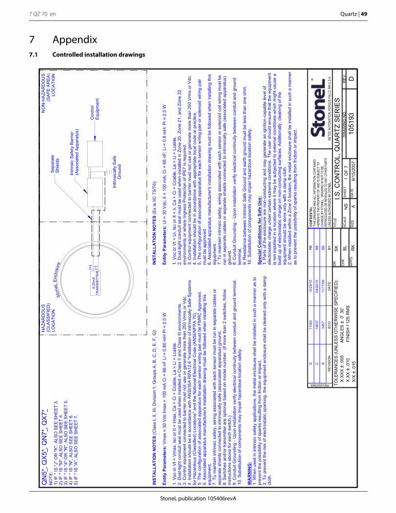
StoneL publication 105406revA
7 QZ 70 en Quartz | 49
7 Appendix7.1 Controlled installation drawings
I.S. C
ON
TRO
L, Q
UA
RTZ
SE
RIE
SN
S
6/15
/200
7
SK BL RK
1051
93S
HEE
T7
A
TOLE
RA
NC
ES
(UN
LES
S O
THE
RW
ISE
SP
EC
IFIE
D):
X.
XXX`
.005
A
NG
LES`
0~ 3
0'
X.XX
`.0
10
F
INIS
H f
125
RM
S
X/X`
.015
D1
SC
ALE
RE
V.
DR
AWIN
G N
O.
SIZ
E
TITL
E
APP
D.
CH
K.
DR
.
DA
TE
CONF
IDEN
TIAL
THIS
DRA
WIN
G AN
D AL
L IN
FORM
ATIO
N CO
NTAI
NED
HERE
IN IS
THE
PRO
PERY
OF
AND
IS S
UBJE
CT T
OCH
ANGE
BY
STON
EL.
DRAW
ING
IS N
OT T
O BE
REPR
ODUC
ED O
R RE
VEAL
ED T
O AN
Y OT
HER
PART
YUN
LESS
AUT
HORI
ZED
BY S
TONE
L.ME
TSO
AUTO
MATIO
N, FE
RGUS
FALL
S, M
N U.
S.A.
REVISIONS
OF
RE
VIS
ION
EC
OD
ATE
BY
HA
ZAR
DO
US
(CLA
SSIF
IED
)LO
CA
TIO
N
NO
N-H
AZA
RD
OU
S(S
AFE
AR
EA)
LOC
ATI
ON
Intri
nsic
ally
Saf
eG
roun
d
Ston
eLEn
clos
ure
4-20
mA
TRAN
SM
ITTE
R(-
)(+
)
INS
TALL
ATI
ON
NO
TES
(Cla
ss I,
II, I
II; D
ivis
ion
1; G
roup
s A,
B, C
, D, E
, F, G
):
Entit
y Pa
ram
eter
s:Vm
ax =
30
Vdc
Imax
= 1
00 m
A C
i = 6
6 nF
Li =
0.8
0 m
H P
i = 2
.0 W
1. V
oc o
r Vt <
Vm
ax, I
sc o
r It <
Imax
, Ca
> C
i + C
cabl
e, L
a >
Li +
Lca
ble.
2. D
ust-t
ight
con
duit
seal
mus
t be
used
whe
n in
stal
led
in C
lass
II a
nd C
lass
III e
nviro
nmen
ts.
3. C
ontro
l equ
ipm
ent c
onne
cted
to b
arrie
r mus
t not
use
or g
ener
ate
mor
e th
an 2
50 V
rms
or V
dc.
4. In
stal
latio
n sh
ould
be
in a
ccor
danc
e w
ith A
NSI
/ISA
RP
A12.
6 "In
stal
latio
n of
Intri
nsic
ally
Saf
e Sy
stem
sfo
r Haz
ardo
us (C
lass
ified
) Loc
atio
ns" a
nd th
e N
atio
nal E
lect
rical
Cod
e (A
NSI
/NFP
A 7
0).
5. T
he c
onfig
urat
ion
of a
ssoc
iate
d ap
para
tus
for e
ach
sens
or w
iring
pai
r mus
t be
FMR
C A
ppro
ved.
6. A
ssoc
iate
d ap
para
tus
man
ufac
ture
r's in
stal
latio
n dr
awin
g m
ust b
e fo
llow
ed w
hen
inst
allin
g th
iseq
uipm
ent.
7. T
o m
aint
ain
intri
nsic
saf
ety,
wiri
ng a
ssoc
iate
d w
ith e
ach
sens
or m
ust b
e ru
n in
sep
arat
e ca
bles
or
sepa
rate
shi
elds
con
nect
ed to
intri
nsic
ally
saf
e (a
ssoc
iate
d ap
para
tus)
gro
und.
8. S
witc
hes
and/
or tr
ansm
itter
are
opt
iona
l bas
ed o
n m
odel
num
ber.
(if m
ore
than
2 s
witc
hes,
follo
win
stru
ctio
ns a
bove
for e
ach
switc
h.)
9. C
ondu
it G
roun
ding
- U
pon
inst
alla
tion
verif
y el
ectri
cal c
ontin
uity
bet
wee
n co
ndui
t and
gro
und
term
inal
.10
. Sub
stitu
tion
of c
ompo
nent
s m
ay im
pair
haza
rdou
s lo
catio
n sa
fety
.
WA
RN
ING
:1.
Whe
n us
ed in
intri
nsic
saf
ety
appl
icat
ions
, the
met
al e
nclo
sure
sha
ll be
inst
alle
d in
suc
h a
man
ner a
s to
prev
ent t
he p
ossi
bilit
y of
spa
rks
resu
lting
from
fric
tion
or im
pact
.2.
To
prev
ent t
he ri
sk o
f ele
ctro
stat
ic s
park
ing,
the
equi
pmen
t enc
losu
re s
hall
be c
lean
ed o
nly
with
a d
amp
clot
h.
INST
ALL
ATI
ON
NO
TES
(Ex
ia II
C T
5/T6
):
Entit
y Pa
ram
eter
s:U
i = 3
0 V
dc; I
i = 1
00 m
A; C
i = 6
6 nF
; Li =
0.8
mH
; Pi =
2.0
W
1. V
oc o
r Vt <
Ui,
Isc
or It
< Ii
, Ca
> C
i + C
cabl
e, L
a >
Li +
Lca
ble.
2. D
ust-t
ight
con
duit
seal
mus
t be
used
whe
n in
stal
led
in Z
one
20, Z
one
21, a
nd Z
one
22en
viro
nmen
ts o
r whe
re In
gres
s Pr
otec
tion
of IP
67 is
requ
ired.
3. C
ontro
l equ
ipm
ent c
onne
cted
to b
arrie
r mus
t not
use
or g
ener
ate
mor
e th
an 2
50 V
rms
or V
dc.
4. In
stal
latio
n sh
ould
be
in a
ccor
danc
e w
ith a
ppro
pria
te lo
cal c
ode
or p
ract
ice.
5. T
he c
onfig
urat
ion
of a
ssoc
iate
d ap
para
tus
for e
ach
sens
or w
iring
pai
r or s
olen
oid
wiri
ng p
air
mus
t be
appr
oved
.6.
Ass
ocia
ted
appa
ratu
s m
anuf
actu
rer's
inst
alla
tion
draw
ing
mus
t be
follo
wed
whe
n in
stal
ling
this
equi
pmen
t.7.
To
mai
ntai
n in
trins
ic s
afet
y, w
iring
ass
ocia
ted
with
eac
h se
nsor
or s
olen
oid
coil
wiri
ng m
ust b
eru
n in
sep
arat
e ca
bles
or s
epar
ate
shie
lds
conn
ecte
d to
intri
nsic
ally
saf
e (a
ssoc
iate
d ap
para
tus)
grou
nd.
8. C
ondu
it G
roun
ding
- U
pon
inst
alla
tion
verif
y el
ectri
cal c
ontin
uity
bet
wee
n co
ndui
t and
gro
und
term
inal
.9.
Res
ista
nce
betw
een
Intri
nsic
Saf
e G
roun
d an
d ea
rth g
roun
d m
ust b
e le
ss th
an o
ne o
hm.
10. S
ubst
itutio
n of
com
pone
nts
may
impa
ir ha
zard
ous
loca
tion
safe
ty.
Spec
ial C
ondi
tions
for S
afe
Use
:1.
Par
ts o
f the
enc
losu
re a
re n
on-c
ondu
ctin
g an
d m
ay g
ener
ate
an ig
nitio
n-ca
pabl
e le
vel o
fel
ectro
stat
ic c
harg
e un
der c
erta
in e
xtre
me
cond
ition
s. T
he u
ser s
houl
d en
sure
that
the
equi
pmen
tis
not
inst
alle
d in
a lo
catio
n w
here
it m
ay b
e su
bjec
ted
to e
xter
nal c
ondi
tions
whi
ch m
ight
cau
se a
build
up
of e
lect
rost
atic
cha
rge
on n
on-c
ondu
ctin
g su
rface
s. A
dditi
onal
ly, c
lean
ing
of th
eeq
uipm
ent s
houl
d be
don
e on
ly w
ith a
dam
p cl
oth.
2. W
hen
inst
alle
d w
ithin
a Z
one
0 lo
catio
n, th
e m
etal
enc
losu
re s
hall
be in
stal
led
in s
uch
a m
anne
ras
to p
reve
nt th
e po
ssib
ility
of s
park
s re
sulti
ng fr
om fr
ictio
n or
impa
ct.
Sepa
rate
Shie
lds
Intri
nsic
Saf
ety
Bar
rier
(Ass
ocia
ted
Appa
ratu
s)
Con
trol
Equi
pmen
t
B11
/17/
09B
B54
57
C04
/20/
15B
B10
637
D12
/29/
15R
B11
363
QN
5*, Q
X5*
, QN
7*, Q
X7*
NO
TE:
1) IF
* IS
"J" O
R "K
", AL
SO S
EE
SH
EET
3.
2) IF
* IS
"M",
ALSO
SE
E S
HEE
T 4.
3) IF
* IS
"4" O
R "
R",
ALSO
SE
E S
HEE
T 5.
4) IF
* IS
"N",
ALS
O S
EE S
HE
ET 6
.5)
IF *
IS "A
", A
LSO
SEE
SH
EET
7.
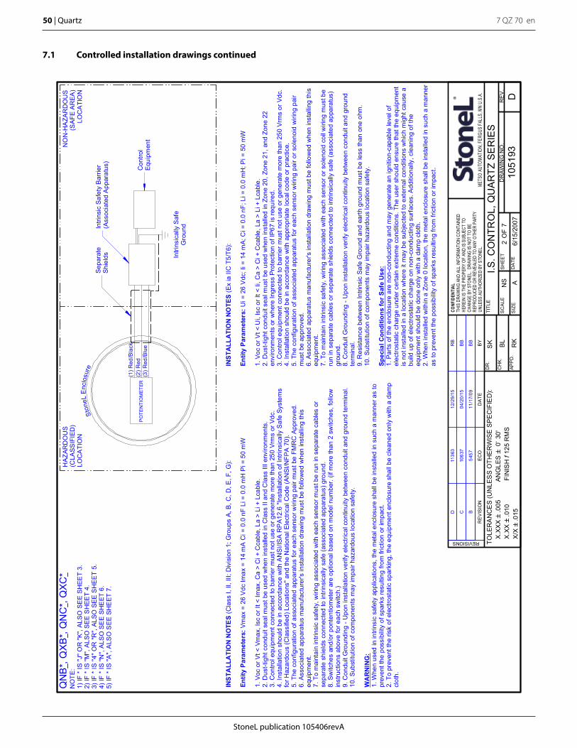
7 QZ 70 en50 | Quartz
StoneL publication 105406revA
I.S. C
ON
TRO
L, Q
UA
RTZ
SE
RIE
SN
S
6/15
/200
7
SK BL RK
1051
93S
HEE
T7
A
TOLE
RA
NC
ES
(UN
LES
S O
THE
RW
ISE
SP
EC
IFIE
D):
X.
XXX`
.005
A
NG
LES`
0~ 3
0'
X.XX
`.0
10
F
INIS
H f
125
RM
S
X/X`
.015
D2
SC
ALE
RE
V.
DR
AWIN
G N
O.
SIZ
E
TITL
E
APP
D.
CH
K.
DR
.
DA
TE
CONF
IDEN
TIAL
THIS
DRA
WIN
G AN
D AL
L IN
FORM
ATIO
N CO
NTAI
NED
HERE
IN IS
THE
PRO
PERY
OF
AND
IS S
UBJE
CT T
OCH
ANGE
BY
STON
EL.
DRAW
ING
IS N
OT T
O BE
REPR
ODUC
ED O
R RE
VEAL
ED T
O AN
Y OT
HER
PART
YUN
LESS
AUT
HORI
ZED
BY S
TONE
L.ME
TSO
AUTO
MATIO
N, FE
RGUS
FALL
S, M
N U.
S.A.
REVISIONS
OF
RE
VIS
ION
EC
OD
ATE
BY
HAZ
ARD
OU
S(C
LASS
IFIE
D)
LOC
ATI
ON
(1) R
ed/B
lack
(2) R
edP
OTE
NTI
OM
ETER
Intri
nsic
ally
Saf
eG
roun
d
NO
N-H
AZA
RD
OU
S(S
AFE
AR
EA)
LOC
ATI
ON
Ston
eLE
nclo
sure
(3) R
ed/B
lue
INS
TALL
ATI
ON
NO
TES
(Cla
ss I,
II, I
II; D
ivis
ion
1; G
roup
s A,
B, C
, D, E
, F, G
):
Entit
y Pa
ram
eter
s:Vm
ax =
26
Vdc
Imax
= 1
4 m
A C
i = 0
.0 n
F Li
= 0
.0 m
H P
i = 5
0 m
W
1. V
oc o
r Vt <
Vm
ax, I
sc o
r It <
Imax
, Ca
> C
i + C
cabl
e, L
a >
Li +
Lca
ble.
2. D
ust-t
ight
con
duit
seal
mus
t be
used
whe
n in
stal
led
in C
lass
II a
nd C
lass
III e
nviro
nmen
ts.
3. C
ontro
l equ
ipm
ent c
onne
cted
to b
arrie
r mus
t not
use
or g
ener
ate
mor
e th
an 2
50 V
rms
or V
dc.
4. In
stal
latio
n sh
ould
be
in a
ccor
danc
e w
ith A
NSI
/ISA
RP
A12.
6 "In
stal
latio
n of
Intri
nsic
ally
Saf
e Sy
stem
sfo
r Haz
ardo
us (C
lass
ified
) Loc
atio
ns" a
nd th
e N
atio
nal E
lect
rical
Cod
e (A
NSI
/NFP
A 7
0).
5. T
he c
onfig
urat
ion
of a
ssoc
iate
d ap
para
tus
for e
ach
sens
or w
iring
pai
r mus
t be
FMR
C A
ppro
ved.
6. A
ssoc
iate
d ap
para
tus
man
ufac
ture
r's in
stal
latio
n dr
awin
g m
ust b
e fo
llow
ed w
hen
inst
allin
g th
iseq
uipm
ent.
7. T
o m
aint
ain
intri
nsic
saf
ety,
wiri
ng a
ssoc
iate
d w
ith e
ach
sens
or m
ust b
e ru
n in
sep
arat
e ca
bles
or
sepa
rate
shi
elds
con
nect
ed to
intri
nsic
ally
saf
e (a
ssoc
iate
d ap
para
tus)
gro
und.
8. S
witc
hes
and/
or p
onte
ntio
met
er a
re o
ptio
nal b
ased
on
mod
el n
umbe
r. (if
mor
e th
an 2
sw
itche
s, fo
llow
inst
ruct
ions
abo
ve fo
r eac
h sw
itch.
)9.
Con
duit
Gro
undi
ng -
Upo
n in
stal
latio
n ve
rify
elec
trica
l con
tinui
ty b
etw
een
cond
uit a
nd g
roun
d te
rmin
al.
10. S
ubst
itutio
n of
com
pone
nts
may
impa
ir ha
zard
ous
loca
tion
safe
ty.
WA
RN
ING
:1.
Whe
n us
ed in
intri
nsic
saf
ety
appl
icat
ions
, the
met
al e
nclo
sure
sha
ll be
inst
alle
d in
suc
h a
man
ner a
s to
prev
ent t
he p
ossi
bilit
y of
spa
rks
resu
lting
from
fric
tion
or im
pact
.2.
To
prev
ent t
he ri
sk o
f ele
ctro
stat
ic s
park
ing,
the
equi
pmen
t enc
losu
re s
hall
be c
lean
ed o
nly
with
a d
amp
clot
h.
INST
ALL
ATI
ON
NO
TES
(Ex
ia II
C T
5/T6
):
Entit
y Pa
ram
eter
s:U
i = 2
6 V
dc; I
i = 1
4 m
A; C
i = 0
.0 n
F; L
i = 0
.0 m
H; P
i = 5
0 m
W
1. V
oc o
r Vt <
Ui,
Isc
or It
< Ii
, Ca
> C
i + C
cabl
e, L
a >
Li +
Lca
ble.
2. D
ust-t
ight
con
duit
seal
mus
t be
used
whe
n in
stal
led
in Z
one
20, Z
one
21, a
nd Z
one
22en
viro
nmen
ts o
r whe
re In
gres
s Pr
otec
tion
of IP
67 is
requ
ired.
3. C
ontro
l equ
ipm
ent c
onne
cted
to b
arrie
r mus
t not
use
or g
ener
ate
mor
e th
an 2
50 V
rms
or V
dc.
4. In
stal
latio
n sh
ould
be
in a
ccor
danc
e w
ith a
ppro
pria
te lo
cal c
ode
or p
ract
ice.
5. T
he c
onfig
urat
ion
of a
ssoc
iate
d ap
para
tus
for e
ach
sens
or w
iring
pai
r or s
olen
oid
wiri
ng p
air
mus
t be
appr
oved
.6.
Ass
ocia
ted
appa
ratu
s m
anuf
actu
rer's
inst
alla
tion
draw
ing
mus
t be
follo
wed
whe
n in
stal
ling
this
equi
pmen
t.7.
To
mai
ntai
n in
trins
ic s
afet
y, w
iring
ass
ocia
ted
with
eac
h se
nsor
or s
olen
oid
coil
wiri
ng m
ust b
eru
n in
sep
arat
e ca
bles
or s
epar
ate
shie
lds
conn
ecte
d to
intri
nsic
ally
saf
e (a
ssoc
iate
d ap
para
tus)
grou
nd.
8. C
ondu
it G
roun
ding
- U
pon
inst
alla
tion
verif
y el
ectri
cal c
ontin
uity
bet
wee
n co
ndui
t and
gro
und
term
inal
.9.
Res
ista
nce
betw
een
Intri
nsic
Saf
e G
roun
d an
d ea
rth g
roun
d m
ust b
e le
ss th
an o
ne o
hm.
10. S
ubst
itutio
n of
com
pone
nts
may
impa
ir ha
zard
ous
loca
tion
safe
ty.
Spec
ial C
ondi
tions
for S
afe
Use
:1.
Par
ts o
f the
enc
losu
re a
re n
on-c
ondu
ctin
g an
d m
ay g
ener
ate
an ig
nitio
n-ca
pabl
e le
vel o
fel
ectro
stat
ic c
harg
e un
der c
erta
in e
xtre
me
cond
ition
s. T
he u
ser s
houl
d en
sure
that
the
equi
pmen
tis
not
inst
alle
d in
a lo
catio
n w
here
it m
ay b
e su
bjec
ted
to e
xter
nal c
ondi
tions
whi
ch m
ight
cau
se a
build
up
of e
lect
rost
atic
cha
rge
on n
on-c
ondu
ctin
g su
rface
s. A
dditi
onal
ly, c
lean
ing
of th
eeq
uipm
ent s
houl
d be
don
e on
ly w
ith a
dam
p cl
oth.
2. W
hen
inst
alle
d w
ithin
a Z
one
0 lo
catio
n, th
e m
etal
enc
losu
re s
hall
be in
stal
led
in s
uch
a m
anne
ras
to p
reve
nt th
e po
ssib
ility
of s
park
s re
sulti
ng fr
om fr
ictio
n or
impa
ct.
Sepa
rate
Shie
lds
Con
trol
Equi
pmen
t
Intri
nsic
Saf
ety
Bar
rier
(Ass
ocia
ted
App
arat
us)
B11
/17/
09B
B54
57
C04
/20/
15B
B10
637
D12
/29/
15R
B11
363
QN
B*,
QX
B*,
QN
C*,
QX
C*
NO
TE:
1) IF
* IS
"J" O
R "K
", AL
SO S
EE
SHEE
T 3.
2) IF
* IS
"M",
ALSO
SEE
SH
EET
4.3)
IF *
IS "4
" OR
"R",
ALSO
SEE
SH
EET
5.4)
IF *
IS "N
", AL
SO
SE
E SH
EET
6.
5) IF
* IS
"A",
ALS
O S
EE S
HE
ET 7
.
7.1 Controlled installation drawings continued
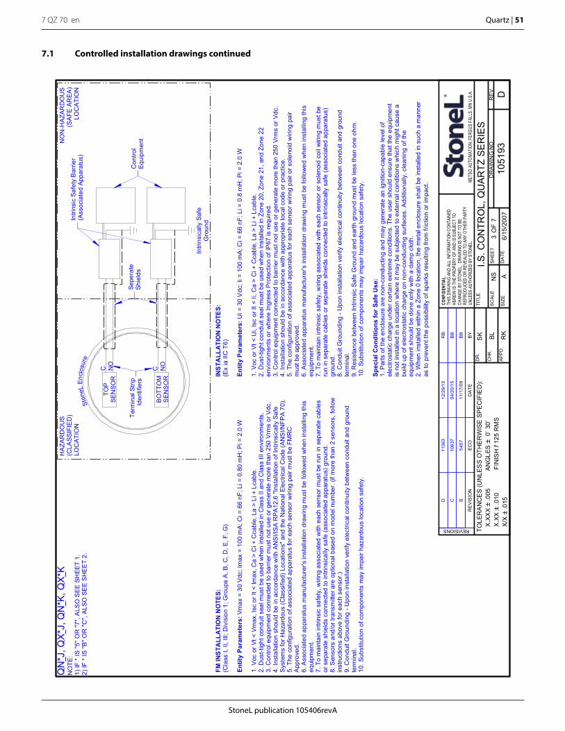
StoneL publication 105406revA
7 QZ 70 en Quartz | 51
I.S. C
ON
TRO
L, Q
UA
RTZ
SE
RIE
SN
S
6/15
/200
7
SK BL RK
1051
93S
HEE
T7
A
TOLE
RA
NC
ES
(UN
LES
S O
THE
RW
ISE
SP
EC
IFIE
D):
X.
XXX`
.005
A
NG
LES`
0~ 3
0'
X.XX
`.0
10
F
INIS
H f
125
RM
S
X/X`
.015
D3
SC
ALE
RE
V.
DR
AWIN
G N
O.
SIZ
E
TITL
E
APP
D.
CH
K.
DR
.
DA
TE
CONF
IDEN
TIAL
THIS
DRA
WIN
G AN
D AL
L IN
FORM
ATIO
N CO
NTAI
NED
HERE
IN IS
THE
PRO
PERY
OF
AND
IS S
UBJE
CT T
OCH
ANGE
BY
STON
EL.
DRAW
ING
IS N
OT T
O BE
REPR
ODUC
ED O
R RE
VEAL
ED T
O AN
Y OT
HER
PART
YUN
LESS
AUT
HORI
ZED
BY S
TONE
L.ME
TSO
AUTO
MATIO
N, FE
RGUS
FALL
S, M
N U.
S.A.
REVISIONS
OF
RE
VIS
ION
EC
OD
ATE
BY
TOP
SEN
SOR
BO
TTO
MS
ENS
OR
Ston
eLEn
clos
ure
HA
ZAR
DO
US
(CLA
SS
IFIE
D)
LOC
ATI
ON
NO
N-H
AZA
RD
OU
S(S
AFE
AR
EA
)LO
CA
TIO
N
C NO
C NO
Intri
nsic
ally
Saf
eG
roun
d
Con
trol
Equi
pmen
t
Intri
nsic
Saf
ety
Bar
rier
(Ass
ocia
ted
Appa
ratu
s)
Sepe
rate
Shie
lds
FM IN
STA
LLA
TIO
N N
OTE
S:(C
lass
I, II
, III;
Div
isio
n 1;
Gro
ups
A, B
, C, D
, E, F
, G)
Entit
y Pa
ram
eter
s:Vm
ax =
30
Vdc
; Im
ax =
100
mA;
Ci =
66
nF; L
i = 0
.80
mH
; Pi =
2.0
W
1. V
oc o
r Vt <
Vm
ax, I
sc o
r It <
Imax
, Ca
> C
i + C
cabl
e, L
a >
Li +
Lca
ble.
2. D
ust-t
ight
con
duit
seal
mus
t be
used
whe
n in
stal
led
in C
lass
II a
nd C
lass
III e
nviro
nmen
ts.
3. C
ontro
l equ
ipm
ent c
onne
cted
to b
arrie
r mus
t not
use
or g
ener
ate
mor
e th
an 2
50 V
rms
or V
dc.
4. In
stal
latio
n sh
ould
be
in a
ccor
danc
e w
ith A
NS
I/IS
A R
PA12
.6 "I
nsta
llatio
n of
Intri
nsic
ally
Saf
eS
yste
ms
for H
azar
dous
(Cla
ssifi
ed) L
ocat
ions
" and
the
Nat
iona
l Ele
ctric
al C
ode
(AN
SI/N
FPA
70)
.5.
The
con
figur
atio
n of
ass
ocia
ted
appa
ratu
s fo
r eac
h se
nsor
wiri
ng p
air m
ust b
e FM
RC
App
rove
d.6.
Ass
ocia
ted
appa
ratu
s m
anuf
actu
rer's
inst
alla
tion
draw
ing
mus
t be
follo
wed
whe
n in
stal
ling
this
equi
pmen
t.7.
To
mai
ntai
n in
trins
ic s
afet
y, w
iring
ass
ocia
ted
with
eac
h se
nsor
mus
t be
run
in s
epar
ate
cabl
esor
sep
arat
e sh
ield
s co
nnec
ted
to in
trins
ical
ly s
afe
(ass
ocia
ted
appa
ratu
s) g
roun
d.8.
Sen
sors
and
/or t
rans
mitt
er a
re o
ptio
nal b
ased
on
mod
el n
umbe
r. (if
mor
e th
an 2
sen
sors
, fol
low
inst
ruct
ions
abo
ve fo
r eac
h se
nsor
.)9.
Con
duit
Gro
undi
ng -
Upo
n in
stal
latio
n ve
rify
elec
trica
l con
tinui
ty b
etw
een
cond
uit a
nd g
roun
dte
rmin
al.
10. S
ubst
itutio
n of
com
pone
nts
may
impa
ir ha
zard
ous
loca
tion
safe
ty.
INS
TALL
ATI
ON
NO
TES:
(Ex
ia II
C T
6)
Entit
y Pa
ram
eter
s:U
i = 3
0 V
dc; I
i = 1
00 m
A; C
i = 6
6 nF
; Li =
0.8
mH
; Pi =
2.0
W
1. V
oc o
r Vt <
Ui,
Isc
or It
< Ii
, Ca
> C
i + C
cabl
e, L
a >
Li +
Lca
ble.
2. D
ust-t
ight
con
duit
seal
mus
t be
used
whe
n in
stal
led
in Z
one
20, Z
one
21, a
nd Z
one
22en
viro
nmen
ts o
r whe
re In
gres
s P
rote
ctio
n of
IP67
is re
quire
d.3.
Con
trol e
quip
men
t con
nect
ed to
bar
rier m
ust n
ot u
se o
r gen
erat
e m
ore
than
250
Vrm
s or
Vdc
.4.
Inst
alla
tion
shou
ld b
e in
acc
orda
nce
with
app
ropr
iate
loca
l cod
e or
pra
ctic
e.5.
The
con
figur
atio
n of
ass
ocia
ted
appa
ratu
s fo
r eac
h se
nsor
wiri
ng p
air o
r sol
enoi
d w
iring
pai
rm
ust b
e ap
prov
ed.
6. A
ssoc
iate
d ap
para
tus
man
ufac
ture
r's in
stal
latio
n dr
awin
g m
ust b
e fo
llow
ed w
hen
inst
allin
g th
iseq
uipm
ent.
7. T
o m
aint
ain
intri
nsic
saf
ety,
wiri
ng a
ssoc
iate
d w
ith e
ach
sens
or o
r sol
enoi
d co
il w
iring
mus
t be
run
in s
epar
ate
cabl
es o
r sep
arat
e sh
ield
s co
nnec
ted
to in
trins
ical
ly s
afe
(ass
ocia
ted
appa
ratu
s)gr
ound
.8.
Con
duit
Gro
undi
ng -
Upo
n in
stal
latio
n ve
rify
elec
trica
l con
tinui
ty b
etw
een
cond
uit a
nd g
roun
dte
rmin
al.
9. R
esis
tanc
e be
twee
n In
trins
ic S
afe
Gro
und
and
earth
gro
und
mus
t be
less
than
one
ohm
.10
. Sub
stitu
tion
of c
ompo
nent
s m
ay im
pair
haza
rdou
s lo
catio
n sa
fety
.
Spec
ial C
ondi
tions
for
Safe
Use
:1.
Par
ts o
f the
enc
losu
re a
re n
on-c
ondu
ctin
g an
d m
ay g
ener
ate
an ig
nitio
n-ca
pabl
e le
vel o
fel
ectro
stat
ic c
harg
e un
der c
erta
in e
xtre
me
cond
ition
s. T
he u
ser s
houl
d en
sure
that
the
equi
pmen
tis
not
inst
alle
d in
a lo
catio
n w
here
it m
ay b
e su
bjec
ted
to e
xter
nal c
ondi
tions
whi
ch m
ight
cau
se a
build
up
of e
lect
rost
atic
cha
rge
on n
on-c
ondu
ctin
g su
rface
s. A
dditi
onal
ly, c
lean
ing
of th
eeq
uipm
ent s
houl
d be
don
e on
ly w
ith a
dam
p cl
oth.
2. W
hen
inst
alle
d w
ithin
a Z
one
0 lo
catio
n, th
e m
etal
enc
losu
re s
hall
be in
stal
led
in s
uch
a m
anne
ras
to p
reve
nt th
e po
ssib
ility
of s
park
s re
sulti
ng fr
om fr
ictio
n or
impa
ct.
B11
/17/
09B
B54
57
C04
/20/
15B
B10
637
D12
/29/
15R
B11
363
Term
inal
Stri
pId
entif
iers
QN
*J, Q
X*J
, QN
*K, Q
X*K
NO
TE:
1) IF
* IS
"5" O
R "7
", A
LSO
SEE
SH
EET
1.2)
IF *
IS "B
" OR
"C",
ALSO
SE
E S
HEE
T 2.
7.1 Controlled installation drawings continued
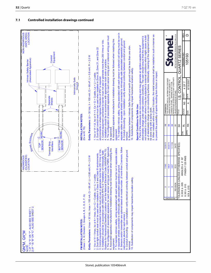
7 QZ 70 en52 | Quartz
StoneL publication 105406revA
I.S. C
ON
TRO
L, Q
UA
RTZ
SE
RIE
SN
S
6/15
/200
7
SK BL RK
1051
93S
HEE
T7
A
TOLE
RA
NC
ES
(UN
LES
S O
THE
RW
ISE
SP
EC
IFIE
D):
X.
XXX`
.005
A
NG
LES`
0~ 3
0'
X.XX
`.0
10
F
INIS
H f
125
RM
S
X/X`
.015
D4
SC
ALE
RE
V.
DR
AWIN
G N
O.
SIZ
E
TITL
E
APP
D.
CH
K.
DR
.
DA
TE
CONF
IDEN
TIAL
THIS
DRA
WIN
G AN
D AL
L IN
FORM
ATIO
N CO
NTAI
NED
HERE
IN IS
THE
PRO
PERY
OF
AND
IS S
UBJE
CT T
OCH
ANGE
BY
STON
EL.
DRAW
ING
IS N
OT T
O BE
REPR
ODUC
ED O
R RE
VEAL
ED T
O AN
Y OT
HER
PART
YUN
LESS
AUT
HORI
ZED
BY S
TONE
L.ME
TSO
AUTO
MATIO
N, FE
RGUS
FALL
S, M
N U.
S.A.
REVISIONS
OF
RE
VIS
ION
EC
OD
ATE
BY
NO
N-H
AZA
RD
OU
S(S
AFE
AR
EA)
LOC
ATIO
N
HA
ZAR
DO
US
(CLA
SS
IFIE
D)
LOC
ATI
ON
Ston
eLEn
clos
ure
Intri
nsic
ally
Saf
eG
roun
d
TOP
SEN
SOR
NO
/NC
C
BO
TTO
MSE
NSO
RN
O/N
CC
FM IN
STA
LLA
TIO
N N
OTE
S:(C
lass
I, II
, III;
Div
isio
n 1;
Gro
ups
A, B
, C, D
, E, F
, G)
Entit
y Pa
ram
eter
s:V
max
= 3
0 Vd
c; Im
ax =
100
mA;
Ci =
66
nF; L
i = 0
.80
mH
; Pi =
2.0
W
1. V
oc o
r Vt <
Vm
ax, I
sc o
r It <
Imax
, Ca
> C
i + C
cabl
e, L
a >
Li +
Lca
ble.
2. D
ust-t
ight
con
duit
seal
mus
t be
used
whe
n in
stal
led
in C
lass
II a
nd C
lass
III e
nviro
nmen
ts.
3. C
ontro
l equ
ipm
ent c
onne
cted
to b
arrie
r mus
t not
use
or g
ener
ate
mor
e th
an 2
50 V
rms
or V
dc.
4. In
stal
latio
n sh
ould
be
in a
ccor
danc
e w
ith A
NS
I/IS
A R
PA12
.6 "I
nsta
llatio
n of
Intri
nsic
ally
Saf
eS
yste
ms
for H
azar
dous
(Cla
ssifi
ed) L
ocat
ions
" and
the
Nat
iona
l Ele
ctric
al C
ode
(AN
SI/N
FPA
70)
.5.
The
con
figur
atio
n of
ass
ocia
ted
appa
ratu
s fo
r eac
h se
nsor
wiri
ng p
air m
ust b
e FM
RC
App
rove
d.6.
Ass
ocia
ted
appa
ratu
s m
anuf
actu
rer's
inst
alla
tion
draw
ing
mus
t be
follo
wed
whe
n in
stal
ling
this
equi
pmen
t.7.
To
mai
ntai
n in
trins
ic s
afet
y, w
iring
ass
ocia
ted
with
eac
h se
nsor
mus
t be
run
in s
epar
ate
cabl
esor
sep
arat
e sh
ield
s co
nnec
ted
to in
trins
ical
ly s
afe
(ass
ocia
ted
appa
ratu
s) g
roun
d.8.
Sen
sors
and
/or t
rans
mitt
er a
re o
ptio
nal b
ased
on
mod
el n
umbe
r. (if
mor
e th
an 2
sen
sors
, fol
low
inst
ruct
ions
abo
ve fo
r eac
h se
nsor
.)9.
Con
duit
Gro
undi
ng -
Upo
n in
stal
latio
n ve
rify
elec
trica
l con
tinui
ty b
etw
een
cond
uit a
nd g
roun
dte
rmin
al.
10. S
ubst
itutio
n of
com
pone
nts
may
impa
ir ha
zard
ous
loca
tion
safe
ty.
INST
ALL
ATI
ON
NO
TES:
(Ex
ia II
C T
6)
Entit
y Pa
ram
eter
s:U
i = 3
0 V
dc; I
i = 1
00 m
A; C
i = 6
6 nF
; Li =
0.8
mH
; Pi =
2.0
W
1. V
oc o
r Vt <
Ui,
Isc
or It
< Ii
, Ca
> C
i + C
cabl
e, L
a >
Li +
Lca
ble.
2. D
ust-t
ight
con
duit
seal
mus
t be
used
whe
n in
stal
led
in Z
one
20, Z
one
21, a
nd Z
one
22en
viro
nmen
ts o
r whe
re In
gres
s Pr
otec
tion
of IP
67 is
requ
ired.
3. C
ontro
l equ
ipm
ent c
onne
cted
to b
arrie
r mus
t not
use
or g
ener
ate
mor
e th
an 2
50 V
rms
or V
dc.
4. In
stal
latio
n sh
ould
be
in a
ccor
danc
e w
ith a
ppro
pria
te lo
cal c
ode
or p
ract
ice.
5. T
he c
onfig
urat
ion
of a
ssoc
iate
d ap
para
tus
for e
ach
sens
or w
iring
pai
r or s
olen
oid
wiri
ng p
air m
ust
be a
ppro
ved.
6. A
ssoc
iate
d ap
para
tus
man
ufac
ture
r's in
stal
latio
n dr
awin
g m
ust b
e fo
llow
ed w
hen
inst
allin
g th
iseq
uipm
ent.
7. T
o m
aint
ain
intri
nsic
saf
ety,
wiri
ng a
ssoc
iate
d w
ith e
ach
sens
or o
r sol
enoi
d co
il w
iring
mus
t be
run
inse
para
te c
able
s or
sep
arat
e sh
ield
s co
nnec
ted
to in
trins
ical
ly s
afe
(ass
ocia
ted
appa
ratu
s) g
roun
d.8.
Con
duit
Gro
undi
ng -
Upo
n in
stal
latio
n ve
rify
elec
trica
l con
tinui
ty b
etw
een
cond
uit a
nd g
roun
dte
rmin
al.
9. R
esis
tanc
e be
twee
n In
trins
ic S
afe
Gro
und
and
earth
gro
und
mus
t be
less
than
one
ohm
.10
. Sub
stitu
tion
of c
ompo
nent
s m
ay im
pair
haza
rdou
s lo
catio
n sa
fety
.
Spec
ial C
ondi
tions
for S
afe
Use
:1.
Par
ts o
f the
enc
losu
re a
re n
on-c
ondu
ctin
g an
d m
ay g
ener
ate
an ig
nitio
n-ca
pabl
e le
vel o
fel
ectro
stat
ic c
harg
e un
der c
erta
in e
xtre
me
cond
ition
s. T
he u
ser s
houl
d en
sure
that
the
equi
pmen
t is
not i
nsta
lled
in a
loca
tion
whe
re it
may
be
subj
ecte
d to
ext
erna
l con
ditio
ns w
hich
mig
ht c
ause
a b
uild
up o
f ele
ctro
stat
ic c
harg
e on
non
-con
duct
ing
surfa
ces.
Add
ition
ally
, cle
anin
g of
the
equi
pmen
t sho
uld
be d
one
only
with
a d
amp
clot
h.2.
Whe
n in
stal
led
with
in a
Zon
e 0
loca
tion,
the
met
al e
nclo
sure
sha
ll be
inst
alle
d in
suc
h a
man
ner a
sto
pre
vent
the
poss
ibili
ty o
f spa
rks
resu
lting
from
fric
tion
or im
pact
.
Con
trol
Equi
pmen
t
Intri
nsic
Saf
ety
Barri
er(A
ssoc
iate
d Ap
para
tus)
B11
/17/
09B
B54
57
C04
/20/
15B
B10
637
D12
/29/
15R
B11
363
Sepe
rate
Shie
lds
Term
inal
Stri
pId
entif
iers
QN
*M, Q
X*M
NO
TE:
1) IF
* IS
"5" O
R "7
", AL
SO S
EE S
HEE
T 1.
2) IF
* IS
"B"
OR
"C",
ALS
O S
EE
SHE
ET 2
.
7.1 Controlled installation drawings continued
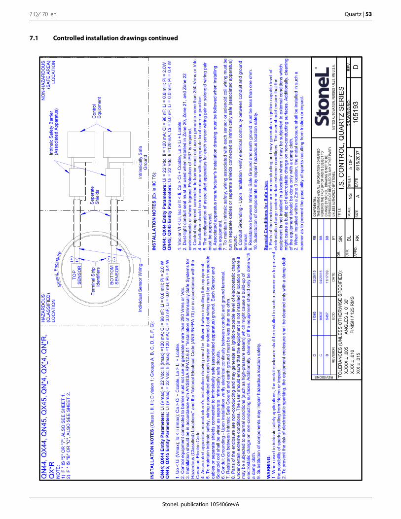
StoneL publication 105406revA
7 QZ 70 en Quartz | 53
I.S. C
ON
TRO
L, Q
UA
RTZ
SE
RIE
SN
S
6/15
/200
7
SK BL RK
1051
93S
HEE
T7
A
TOLE
RA
NC
ES
(UN
LES
S O
THE
RW
ISE
SP
EC
IFIE
D):
X.
XXX`
.005
A
NG
LES`
0~ 3
0'
X.XX
`.0
10
F
INIS
H f
125
RM
S
X/X`
.015
D5
SC
ALE
RE
V.
DR
AWIN
G N
O.
SIZ
E
TITL
E
APP
D.
CH
K.
DR
.
DA
TE
CONF
IDEN
TIAL
THIS
DRA
WIN
G AN
D AL
L IN
FORM
ATIO
N CO
NTAI
NED
HERE
IN IS
THE
PRO
PERY
OF
AND
IS S
UBJE
CT T
OCH
ANGE
BY
STON
EL.
DRAW
ING
IS N
OT T
O BE
REPR
ODUC
ED O
R RE
VEAL
ED T
O AN
Y OT
HER
PART
YUN
LESS
AUT
HORI
ZED
BY S
TONE
L.ME
TSO
AUTO
MATIO
N, FE
RGUS
FALL
S, M
N U.
S.A.
REVISIONS
OF
RE
VIS
ION
EC
OD
ATE
BY
TOP
SEN
SOR
BO
TTO
MS
ENS
OR
Ston
eLEn
clos
ure
HA
ZAR
DO
US
(CLA
SS
IFIE
D)
LOC
ATI
ON
NO
N-H
AZA
RD
OU
S(S
AFE
AR
EA)
LOC
ATI
ON
(+)
(-)
Intri
nsic
ally
Saf
eG
roun
d
(-)(+)
Con
trol
Equi
pmen
t
Intri
nsic
Saf
ety
Bar
rier
(Ass
ocia
ted
Appa
ratu
s)
Sepe
rate
Shie
lds
INST
ALL
ATI
ON
NO
TES
(Cla
ss I,
II, I
II; D
ivis
ion
1; G
roup
s A
, B, C
, D, E
, F, G
):
QN
44; Q
X44
Entit
y Pa
ram
eter
s:U
i (V
max
) = 2
2 V
dc; I
i (Im
ax) =
120
mA
; Ci =
98
nF; L
i = 0
.8 m
H; P
i = 2
.0 W
QN
45; Q
X45
Entit
y Pa
ram
eter
s:U
i (V
max
) = 2
2 V
dc; I
i (Im
ax) =
120
mA
; Ci =
3.0
nF;
Li =
0.0
mH
; Pi =
0.4
W
1. U
o <
Ui (
Vm
ax);
Io <
Ii (I
max
); C
a >
Ci +
Cca
ble,
La
> Li
+ L
cabl
e.2.
Con
trol e
quip
men
t con
nect
ed to
bar
rier m
ust n
ot u
se o
r gen
erat
e m
ore
than
250
Vrm
s or
Vdc
.3.
Inst
alla
tion
shou
ld b
e in
acc
orda
nce
with
AN
SI/IS
A R
PA1
2.6.
01 "I
nsta
llatio
n of
Intri
nsic
ally
Saf
e Sy
stem
s fo
rH
azar
dous
(Cla
ssifi
ed) L
ocat
ions
" and
the
Nat
iona
l Ele
ctric
al C
ode
(AN
SI/N
FPA
70)
or i
n ac
cord
ance
with
the
Can
adia
n El
ectri
c C
ode.
4. A
ssoc
iate
d ap
para
tus
man
ufac
ture
r's in
stal
latio
n dr
awin
g m
ust b
e fo
llow
ed w
hen
inst
allin
g th
is e
quip
men
t.5.
To
mai
ntai
n in
trins
ic s
afet
y, w
iring
ass
ocia
ted
with
eac
h se
nsor
or s
olen
oid
coil
wiri
ng m
ust b
e ru
n in
sep
arat
eca
bles
or s
epar
ate
shie
lds
conn
ecte
d to
intri
nsic
ally
saf
e (a
ssoc
iate
d ap
para
tus)
gro
und.
Eac
h Se
nsor
and
Sole
noid
coi
l sha
ll be
wire
d as
sep
arat
e in
trins
ical
ly s
afe
circ
uits
.6.
Con
duit
Gro
undi
ng -
Upo
n in
stal
latio
n ve
rify
elec
trica
l con
tinui
ty b
etw
een
cond
uit a
nd g
roun
d te
rmin
al.
7. R
esis
tanc
e be
twee
n In
trins
ic S
afe
Gro
und
and
earth
gro
und
mus
t be
less
than
one
ohm
.8.
Par
ts o
f the
enc
losu
re a
re n
on-c
ondu
ctin
g an
d m
ay g
ener
ate
an ig
nitio
n-ca
pabl
e le
vel o
f ele
ctro
stat
ic c
harg
eun
der c
erta
in e
xtre
me
cond
ition
s. T
he u
ser s
houl
d en
sure
that
the
equi
pmen
t is
not i
nsta
lled
in lo
catio
n w
here
itm
ay b
e su
bjec
ted
to e
xter
nal c
ondi
tions
(suc
h as
hig
h-pr
essu
re s
team
) whi
ch m
ight
cau
se a
bui
ld-u
p of
elec
trost
atic
cha
rge
on n
on-c
ondu
ctin
g su
rface
s. A
dditi
onal
ly, c
lean
ing
of th
e eq
uipm
ent s
houl
d on
ly b
e do
ne w
itha
dam
p cl
oth.
9. S
ubst
itutio
n of
com
pone
nts
may
impa
ir ha
zard
ous
loca
tion
safe
ty.
WA
RN
ING
:1.
Whe
n us
ed in
intri
nsic
saf
ety
appl
icat
ions
, the
met
al e
nclo
sure
sha
ll be
inst
alle
d in
suc
h a
man
ner a
s to
pre
vent
the
poss
ibilit
y of
spa
rks
resu
lting
from
fric
tion
or im
pact
.2.
To
prev
ent t
he ri
sk o
f ele
ctro
stat
ic s
park
ing,
the
equi
pmen
t enc
losu
re s
hall
be c
lean
ed o
nly
with
a d
amp
clot
h.
INST
ALL
ATI
ON
NO
TES
(Ex
ia II
C T
6):
QN
44; Q
X44
Entit
y Pa
ram
eter
s:U
i = 2
2 Vd
c; Ii
= 1
20 m
A; C
i = 9
8 nF
; Li =
0.8
mH
; Pi =
2.0
WQ
N45
; QX4
5 En
tity
Para
met
ers:
Ui =
22
Vdc;
Ii =
120
mA
; Ci =
3.0
nF;
Li =
0.0
mH
; Pi =
0.4
W
1. V
oc o
r Vt <
Ui,
Isc
or It
< Ii
, Ca
> C
i + C
cabl
e, L
a >
Li +
Lca
ble.
2. D
ust-t
ight
con
duit
seal
mus
t be
used
whe
n in
stal
led
in Z
one
20, Z
one
21, a
nd Z
one
22en
viro
nmen
ts o
r whe
re In
gres
s Pr
otec
tion
of IP
67 is
requ
ired.
3. C
ontro
l equ
ipm
ent c
onne
cted
to b
arrie
r mus
t not
use
or g
ener
ate
mor
e th
an 2
50 V
rms
or V
dc.
4. In
stal
latio
n sh
ould
be
in a
ccor
danc
e w
ith a
ppro
pria
te lo
cal c
ode
or p
ract
ice.
5. T
he c
onfig
urat
ion
of a
ssoc
iate
d ap
para
tus
for e
ach
sens
or w
iring
pai
r or s
olen
oid
wiri
ng p
air
mus
t be
appr
oved
.6.
Ass
ocia
ted
appa
ratu
s m
anuf
actu
rer's
inst
alla
tion
draw
ing
mus
t be
follo
wed
whe
n in
stal
ling
this
equ
ipm
ent.
7. T
o m
aint
ain
intri
nsic
saf
ety,
wiri
ng a
ssoc
iate
d w
ith e
ach
sens
or o
r sol
enoi
d co
il w
iring
mus
t be
run
in s
epar
ate
cabl
es o
r sep
arat
e sh
ield
s co
nnec
ted
to in
trins
ical
ly s
afe
(ass
ocia
ted
appa
ratu
s)gr
ound
.8.
Con
duit
Gro
undi
ng -
Upo
n in
stal
latio
n ve
rify
elec
trica
l con
tinui
ty b
etw
een
cond
uit a
nd g
roun
dte
rmin
al.
9. R
esis
tanc
e be
twee
n In
trins
ic S
afe
Gro
und
and
earth
gro
und
mus
t be
less
than
one
ohm
.10
. Sub
stitu
tion
of c
ompo
nent
s m
ay im
pair
haza
rdou
s lo
catio
n sa
fety
.
Spec
ial C
ondi
tions
for S
afe
Use
:1.
Par
ts o
f the
enc
losu
re a
re n
on-c
ondu
ctin
g an
d m
ay g
ener
ate
an ig
nitio
n-ca
pabl
e le
vel o
fel
ectro
stat
ic c
harg
e un
der c
erta
in e
xtre
me
cond
ition
s. T
he u
ser s
houl
d en
sure
that
the
equi
pmen
t is
not i
nsta
lled
in a
loca
tion
whe
re it
may
be
subj
ecte
d to
ext
erna
l con
ditio
ns w
hich
mig
ht c
ause
a b
uild
up
of e
lect
rost
atic
cha
rge
on n
on-c
ondu
ctin
g su
rface
s. A
dditi
onal
ly, c
lean
ing
of th
e eq
uipm
ent s
houl
d be
don
e on
ly w
ith a
dam
p cl
oth.
2. W
hen
inst
alle
d w
ithin
a Z
one
0 lo
catio
n, th
e m
etal
enc
losu
re s
hall
be in
stal
led
in s
uch
am
anne
r as
to p
reve
nt th
e po
ssib
ility
of s
park
s re
sulti
ng fr
om fr
ictio
n or
impa
ct.
Term
inal
Stri
pId
entif
iers
Indi
vidu
al S
enso
r Wiri
ng
B11
/17/
09B
B54
57
C04
/20/
15B
B10
637
D12
/29/
15R
B11
363
QN
44, Q
X44
, QN
45, Q
X45
, QN
*4, Q
X*4
, QN
*R,
QX*
RN
OTE
:1)
IF *
IS "5
" OR
"7",
ALSO
SE
E S
HEE
T 1.
2) IF
* IS
"B" O
R "C
", A
LSO
SE
E SH
EET
2.
7.1 Controlled installation drawings continued

7 QZ 70 en54 | Quartz
StoneL publication 105406revA
For T
6Ta
* =
For T
5Ta
* =
For
T4...
T1Ta
* =
Ui V
Ii mA
Pi
mW
Ci
nFLi mH
-25°
C to
56°C
-25°
C to
68°C
-25°
C to
80°C
1625
3440
0.05
-25°
C to
49°C
-25°
C to
61°C
-25°
C to
80°C
1625
6440
0.05
-25°
C to
28°C
-25°
C to
40°C
-25°
C to
68°C
1652
169
400.
05
-25°
C to
13°C
-25°
C to
25°C
-25°
C to
53°C
1676
242
400.
05
I.S. C
ON
TRO
L, Q
UA
RTZ
SE
RIE
SN
S
6/15
/200
7
SK BL RK
1051
93S
HEE
T7
A
TOLE
RA
NC
ES
(UN
LES
S O
THE
RW
ISE
SP
EC
IFIE
D):
X.
XXX`
.005
A
NG
LES`
0~ 3
0'
X.XX
`.0
10
F
INIS
H f
125
RM
S
X/X`
.015
D6
SC
ALE
RE
V.
DR
AWIN
G N
O.
SIZ
E
TITL
E
APP
D.
CH
K.
DR
.
DA
TE
CONF
IDEN
TIAL
THIS
DRA
WIN
G AN
D AL
L IN
FORM
ATIO
N CO
NTAI
NED
HERE
IN IS
THE
PRO
PERY
OF
AND
IS S
UBJE
CT T
OCH
ANGE
BY
STON
EL.
DRAW
ING
IS N
OT T
O BE
REPR
ODUC
ED O
R RE
VEAL
ED T
O AN
Y OT
HER
PART
YUN
LESS
AUT
HORI
ZED
BY S
TONE
L.ME
TSO
AUTO
MATIO
N, FE
RGUS
FALL
S, M
N U.
S.A.
REVISIONS
OF
RE
VIS
ION
EC
OD
ATE
BY
TOP
SEN
SO
R
BO
TTO
MSE
NSO
R
Ston
eLEn
c los
ure
HA
ZAR
DO
US
(CLA
SSIF
IED
)LO
CA
TIO
N
NO
N-H
AZA
RD
OU
S(S
AFE
AR
EA)
LOC
ATI
ON
(+)
(-)
Intri
nsic
ally
Saf
eG
roun
d
(-)
(+)
Con
trol
Equi
pmen
t
Intri
nsic
Saf
ety
Bar
rier
(Ass
ocia
ted
Appa
ratu
s)
Sepe
rate
Shie
lds
INST
ALL
ATI
ON
NO
TES
(Cla
ss I,
II, I
II; D
ivis
ion
1; G
roup
s A,
B, C
, D, E
, F, G
):
1. U
o <
Ui (
Vmax
); Io
< Ii
(Im
ax);
Ca
> C
i + C
cabl
e, L
a >
Li +
Lca
ble.
2. C
ontro
l equ
ipm
ent c
onne
cted
to b
arrie
r mus
t not
use
or g
ener
ate
mor
e th
an 2
50 V
rms
or V
dc.
3. In
stal
latio
n sh
ould
be
in a
ccor
danc
e w
ith A
NSI
/ISA
RPA
12.6
.01
"Inst
alla
tion
of In
trins
ical
ly S
afe
Sys
tem
s fo
r Haz
ardo
us (C
lass
ified
) Loc
atio
ns" a
nd th
e N
atio
nal E
lect
rical
Cod
e (A
NS
I/NFP
A 7
0) o
r in
acco
rdan
ce w
ith th
e C
anad
ian
Elec
tric
Cod
e.4.
Ass
ocia
ted
appa
ratu
s m
anuf
actu
rer's
inst
alla
tion
draw
ing
mus
t be
follo
wed
whe
n in
stal
ling
this
equi
pmen
t.5.
To
mai
ntai
n in
trins
ic s
afet
y, w
iring
ass
ocia
ted
with
eac
h se
nsor
or s
olen
oid
coil
wiri
ng m
ust b
e ru
n in
sepa
rate
cab
les
or s
epar
ate
shie
lds
conn
ecte
d to
intri
nsic
ally
saf
e (a
ssoc
iate
d ap
para
tus)
gro
und.
Eac
hS
enso
r and
Sol
enoi
d co
il sh
all b
e w
ired
as s
epar
ate
intri
nsic
ally
saf
e ci
rcui
ts.
6. C
ondu
it G
roun
ding
- U
pon
inst
alla
tion
verif
y el
ectri
cal c
ontin
uity
bet
wee
n co
ndui
t and
gro
und
term
inal
.7.
Res
ista
nce
betw
een
Intri
nsic
Saf
e G
roun
d an
d ea
rth g
roun
d m
ust b
e le
ss th
an o
ne o
hm.
8. P
arts
of t
he e
nclo
sure
are
non
-con
duct
ing
and
may
gen
erat
e an
igni
tion-
capa
ble
leve
l of e
lect
rost
atic
char
ge u
nder
cer
tain
ext
rem
e co
nditi
ons.
The
use
r sho
uld
ensu
re th
at th
e eq
uipm
ent i
s no
t ins
talle
d in
loca
tion
whe
re it
may
be
subj
ecte
d to
ext
erna
l con
ditio
ns (s
uch
as h
igh-
pres
sure
ste
am) w
hich
mig
htca
use
a bu
ild-u
p of
ele
ctro
stat
ic c
harg
e on
non
-con
duct
ing
surfa
ces.
Add
ition
ally
, cle
anin
g of
the
equi
pmen
t sho
uld
only
be
done
with
a d
amp
clot
h.9.
Sub
stitu
tion
of c
ompo
nent
s m
ay im
pair
haza
rdou
s lo
catio
n sa
fety
.
WA
RN
ING
:1.
Whe
n us
ed in
intri
nsic
saf
ety
appl
icat
ions
, the
met
al e
nclo
sure
sha
ll be
inst
alle
d in
suc
h a
man
ner a
s to
prev
ent t
he p
ossi
bilit
y of
spa
rks
resu
lting
from
fric
tion
or im
pact
.2.
To
prev
ent t
he ri
sk o
f ele
ctro
stat
ic s
park
ing,
the
equi
pmen
t enc
losu
re s
hall
be c
lean
ed o
nly
with
a d
amp
clot
h.
INST
ALL
ATI
ON
NO
TES
(Ex
ia II
C T
6...T
1 Ta
*):
1. V
oc o
r Vt <
Ui,
Isc
or It
< Ii
, Ca
> C
i + C
cabl
e, L
a >
Li +
Lca
ble.
2. D
ust-t
ight
con
duit
seal
mus
t be
used
whe
n in
stal
led
in Z
one
20, Z
one
21, a
nd Z
one
22en
viro
nmen
ts o
r whe
re In
gres
s P
rote
ctio
n of
IP67
is re
quire
d.3.
Con
trol e
quip
men
t con
nect
ed to
bar
rier m
ust n
ot u
se o
r gen
erat
e m
ore
than
250
Vrm
s or
Vdc
.4.
Inst
alla
tion
shou
ld b
e in
acc
orda
nce
with
app
ropr
iate
loca
l cod
e or
pra
ctic
e.5.
The
con
figur
atio
n of
ass
ocia
ted
appa
ratu
s fo
r eac
h se
nsor
wiri
ng p
air o
r sol
enoi
d w
iring
pai
rm
ust b
e ap
prov
ed.
6. A
ssoc
iate
d ap
para
tus
man
ufac
ture
r's in
stal
latio
n dr
awin
g m
ust b
e fo
llow
ed w
hen
inst
allin
g th
iseq
uipm
ent.
7. T
o m
aint
ain
intri
nsic
saf
ety,
wiri
ng a
ssoc
iate
d w
ith e
ach
sens
or o
r sol
enoi
d co
il w
iring
mus
t be
run
in s
epar
ate
cabl
es o
r sep
arat
e sh
ield
s co
nnec
ted
to in
trins
ical
ly s
afe
(ass
ocia
ted
appa
ratu
s)gr
ound
.8.
Con
duit
Gro
undi
ng -
Upo
n in
stal
latio
n ve
rify
elec
trica
l con
tinui
ty b
etw
een
cond
uit a
nd g
roun
dte
rmin
al.
9. R
esis
tanc
e be
twee
n In
trins
ic S
afe
Gro
und
and
earth
gro
und
mus
t be
less
than
one
ohm
.10
. Sub
stitu
tion
of c
ompo
nent
s m
ay im
pair
haza
rdou
s lo
catio
n sa
fety
.
Spec
ial C
ondi
tions
for S
afe
Use
:1.
Par
ts o
f the
enc
losu
re a
re n
on-c
ondu
ctin
g an
d m
ay g
ener
ate
an ig
nitio
n-ca
pabl
e le
vel o
fel
ectro
stat
ic c
harg
e un
der c
erta
in e
xtre
me
cond
ition
s. T
he u
ser s
houl
d en
sure
that
the
equi
pmen
tis
not
inst
alle
d in
a lo
catio
n w
here
it m
ay b
e su
bjec
ted
to e
xter
nal c
ondi
tions
whi
ch m
ight
cau
se a
build
up
of e
lect
rost
atic
cha
rge
on n
on-c
ondu
ctin
g su
rface
s. A
dditi
onal
ly, c
lean
ing
of th
e eq
uipm
ent
shou
ld b
e do
ne o
nly
with
a d
amp
clot
h.2.
Whe
n in
stal
led
with
in a
Zon
e 0
loca
tion,
the
met
al e
nclo
sure
sha
ll be
inst
alle
d in
suc
h a
man
ner
as to
pre
vent
the
poss
ibili
ty o
f spa
rks
resu
lting
from
fric
tion
or im
pact
.
Term
inal
Stri
pId
entif
iers
Indi
vidu
al S
enso
r Wiri
ng
For Q
N_N
, QX_
N T
empe
ratu
re C
odes
, Am
bien
t Tem
pera
ture
s an
dEn
ergy
Lim
itatio
n Pa
ram
eter
s se
e Ta
ble
belo
w:
B11
/17/
09B
B54
57
C04
/20/
15B
B10
637
D12
/29/
15R
B11
363
QN
* N, Q
X*N
NO
TE:
1) IF
* IS
"5" O
R "
7", A
LSO
SE
E SH
EET
1.
2) IF
* IS
"B" O
R "C
", A
LSO
SEE
SH
EET
2.
7.1 Controlled installation drawings continued
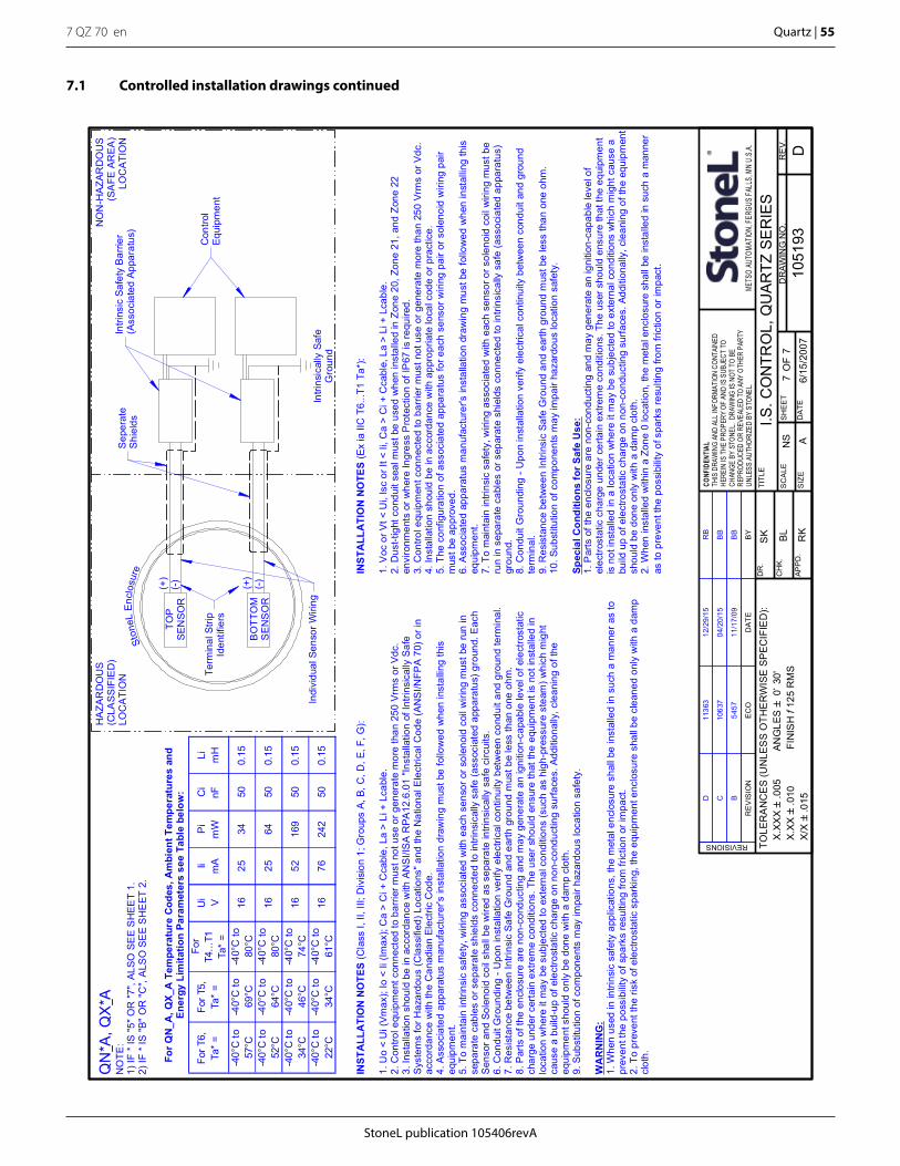
StoneL publication 105406revA
7 QZ 70 en Quartz | 55
For T
6,Ta
* =
For T
5,Ta
* =
For
T4...
T1Ta
* =
Ui V
Ii mA
Pi
mW
Ci
nFLi mH
-40°
C to
57°C
-40°
C to
69°C
-40°
C to
80°C
1625
3450
0.15
-40°
C to
52°C
-40°
C to
64°C
-40°
C to
80°C
1625
6450
0.15
-40°
C to
34°C
-40°
C to
46°C
-40°
C to
74°C
1652
169
500.
15
-40°
C to
22°C
-40°
C to
34°C
-40°
C to
61°C
1676
242
500.
15
I.S. C
ON
TRO
L, Q
UA
RTZ
SE
RIE
SN
S
6/15
/200
7
SK BL RK
1051
93S
HEE
T7
A
TOLE
RA
NC
ES
(UN
LES
S O
THE
RW
ISE
SP
EC
IFIE
D):
X.
XXX`
.005
A
NG
LES`
0~ 3
0'
X.XX
`.0
10
F
INIS
H f
125
RM
S
X/X`
.015
D7
SC
ALE
RE
V.
DR
AWIN
G N
O.
SIZ
E
TITL
E
APP
D.
CH
K.
DR
.
DA
TE
CONF
IDEN
TIAL
THIS
DRA
WIN
G AN
D AL
L IN
FORM
ATIO
N CO
NTAI
NED
HERE
IN IS
THE
PRO
PERY
OF
AND
IS S
UBJE
CT T
OCH
ANGE
BY
STON
EL.
DRAW
ING
IS N
OT T
O BE
REPR
ODUC
ED O
R RE
VEAL
ED T
O AN
Y OT
HER
PART
YUN
LESS
AUT
HORI
ZED
BY S
TONE
L.ME
TSO
AUTO
MATIO
N, FE
RGUS
FALL
S, M
N U.
S.A.
REVISIONS
OF
RE
VIS
ION
EC
OD
ATE
BY
TOP
SEN
SOR
BO
TTO
MS
ENS
OR
Ston
eLEn
clos
ure
HA
ZAR
DO
US
(CLA
SS
IFIE
D)
LOC
ATI
ON
NO
N-H
AZA
RD
OU
S(S
AFE
AR
EA
)LO
CA
TIO
N
(+)
(-)
Intri
nsic
ally
Saf
eG
roun
d
(-)(+)
Con
trol
Equi
pmen
t
Intri
nsic
Saf
ety
Bar
rier
(Ass
ocia
ted
Appa
ratu
s)S
eper
ate
Shi
elds
INST
ALL
ATI
ON
NO
TES
(Cla
ss I,
II, I
II; D
ivis
ion
1; G
roup
s A,
B, C
, D, E
, F, G
):
1. U
o <
Ui (
Vmax
); Io
< Ii
(Im
ax);
Ca
> C
i + C
cabl
e, L
a >
Li +
Lca
ble.
2. C
ontro
l equ
ipm
ent c
onne
cted
to b
arrie
r mus
t not
use
or g
ener
ate
mor
e th
an 2
50 V
rms
or V
dc.
3. In
stal
latio
n sh
ould
be
in a
ccor
danc
e w
ith A
NSI
/ISA
RPA
12.6
.01
"Inst
alla
tion
of In
trins
ical
ly S
afe
Sys
tem
s fo
r Haz
ardo
us (C
lass
ified
) Loc
atio
ns" a
nd th
e N
atio
nal E
lect
rical
Cod
e (A
NS
I/NFP
A 7
0) o
r in
acco
rdan
ce w
ith th
e C
anad
ian
Elec
tric
Cod
e.4.
Ass
ocia
ted
appa
ratu
s m
anuf
actu
rer's
inst
alla
tion
draw
ing
mus
t be
follo
wed
whe
n in
stal
ling
this
equi
pmen
t.5.
To
mai
ntai
n in
trins
ic s
afet
y, w
iring
ass
ocia
ted
with
eac
h se
nsor
or s
olen
oid
coil
wiri
ng m
ust b
e ru
n in
sepa
rate
cab
les
or s
epar
ate
shie
lds
conn
ecte
d to
intri
nsic
ally
saf
e (a
ssoc
iate
d ap
para
tus)
gro
und.
Eac
hS
enso
r and
Sol
enoi
d co
il sh
all b
e w
ired
as s
epar
ate
intri
nsic
ally
saf
e ci
rcui
ts.
6. C
ondu
it G
roun
ding
- U
pon
inst
alla
tion
verif
y el
ectri
cal c
ontin
uity
bet
wee
n co
ndui
t and
gro
und
term
inal
.7.
Res
ista
nce
betw
een
Intri
nsic
Saf
e G
roun
d an
d ea
rth g
roun
d m
ust b
e le
ss th
an o
ne o
hm.
8. P
arts
of t
he e
nclo
sure
are
non
-con
duct
ing
and
may
gen
erat
e an
igni
tion-
capa
ble
leve
l of e
lect
rost
atic
char
ge u
nder
cer
tain
ext
rem
e co
nditi
ons.
The
use
r sho
uld
ensu
re th
at th
e eq
uipm
ent i
s no
t ins
talle
d in
loca
tion
whe
re it
may
be
subj
ecte
d to
ext
erna
l con
ditio
ns (s
uch
as h
igh-
pres
sure
ste
am) w
hich
mig
htca
use
a bu
ild-u
p of
ele
ctro
stat
ic c
harg
e on
non
-con
duct
ing
surfa
ces.
Add
ition
ally
, cle
anin
g of
the
equi
pmen
t sho
uld
only
be
done
with
a d
amp
clot
h.9.
Sub
stitu
tion
of c
ompo
nent
s m
ay im
pair
haza
rdou
s lo
catio
n sa
fety
.
WA
RN
ING
:1.
Whe
n us
ed in
intri
nsic
saf
ety
appl
icat
ions
, the
met
al e
nclo
sure
sha
ll be
inst
alle
d in
suc
h a
man
ner a
s to
prev
ent t
he p
ossi
bilit
y of
spa
rks
resu
lting
from
fric
tion
or im
pact
.2.
To
prev
ent t
he ri
sk o
f ele
ctro
stat
ic s
park
ing,
the
equi
pmen
t enc
losu
re s
hall
be c
lean
ed o
nly
with
a d
amp
clot
h.
INST
ALL
ATI
ON
NO
TES
(Ex
ia II
C T
6...T
1 Ta
*):
1. V
oc o
r Vt <
Ui,
Isc
or It
< Ii
, Ca
> C
i + C
cabl
e, L
a >
Li +
Lca
ble.
2. D
ust-t
ight
con
duit
seal
mus
t be
used
whe
n in
stal
led
in Z
one
20, Z
one
21, a
nd Z
one
22en
viro
nmen
ts o
r whe
re In
gres
s P
rote
ctio
n of
IP67
is re
quire
d.3.
Con
trol e
quip
men
t con
nect
ed to
bar
rier m
ust n
ot u
se o
r gen
erat
e m
ore
than
250
Vrm
s or
Vdc
.4.
Inst
alla
tion
shou
ld b
e in
acc
orda
nce
with
app
ropr
iate
loca
l cod
e or
pra
ctic
e.5.
The
con
figur
atio
n of
ass
ocia
ted
appa
ratu
s fo
r eac
h se
nsor
wiri
ng p
air o
r sol
enoi
d w
iring
pai
rm
ust b
e ap
prov
ed.
6. A
ssoc
iate
d ap
para
tus
man
ufac
ture
r's in
stal
latio
n dr
awin
g m
ust b
e fo
llow
ed w
hen
inst
allin
g th
iseq
uipm
ent.
7. T
o m
aint
ain
intri
nsic
saf
ety,
wiri
ng a
ssoc
iate
d w
ith e
ach
sens
or o
r sol
enoi
d co
il w
iring
mus
t be
run
in s
epar
ate
cabl
es o
r sep
arat
e sh
ield
s co
nnec
ted
to in
trins
ical
ly s
afe
(ass
ocia
ted
appa
ratu
s)gr
ound
.8.
Con
duit
Gro
undi
ng -
Upo
n in
stal
latio
n ve
rify
elec
trica
l con
tinui
ty b
etw
een
cond
uit a
nd g
roun
dte
rmin
al.
9. R
esis
tanc
e be
twee
n In
trins
ic S
afe
Gro
und
and
earth
gro
und
mus
t be
less
than
one
ohm
.10
. Sub
stitu
tion
of c
ompo
nent
s m
ay im
pair
haza
rdou
s lo
catio
n sa
fety
.
Spec
ial C
ondi
tions
for S
afe
Use
:1.
Par
ts o
f the
enc
losu
re a
re n
on-c
ondu
ctin
g an
d m
ay g
ener
ate
an ig
nitio
n-ca
pabl
e le
vel o
fel
ectro
stat
ic c
harg
e un
der c
erta
in e
xtre
me
cond
ition
s. T
he u
ser s
houl
d en
sure
that
the
equi
pmen
tis
not
inst
alle
d in
a lo
catio
n w
here
it m
ay b
e su
bjec
ted
to e
xter
nal c
ondi
tions
whi
ch m
ight
cau
se a
build
up
of e
lect
rost
atic
cha
rge
on n
on-c
ondu
ctin
g su
rface
s. A
dditi
onal
ly, c
lean
ing
of th
e eq
uipm
ent
shou
ld b
e do
ne o
nly
with
a d
amp
clot
h.2.
Whe
n in
stal
led
with
in a
Zon
e 0
loca
tion,
the
met
al e
nclo
sure
sha
ll be
inst
alle
d in
suc
h a
man
ner
as to
pre
vent
the
poss
ibili
ty o
f spa
rks
resu
lting
from
fric
tion
or im
pact
.
Term
inal
Stri
pId
entif
iers
Indi
vidu
al S
enso
r Wiri
ng
For Q
N_A
, QX_
A T
empe
ratu
re C
odes
, Am
bien
t Tem
pera
ture
s an
dEn
ergy
Lim
itatio
n Pa
ram
eter
s se
e Ta
ble
belo
w:
B11
/17/
09B
B54
57
C04
/20/
15B
B10
637
D12
/29/
15R
B11
363
QN
*A, Q
X*A
NO
TE:
1) IF
* IS
"5" O
R "7
", AL
SO S
EE
SH
EET
1.2)
IF *
IS "B
" O
R "C
", A
LSO
SE
E S
HE
ET 2
.
7.1 Controlled installation drawings continued

StoneL Production CenterNorth America, 26271 US Hwy 59, Fergus Falls, MN 56537, USA. Tel. +1 218 739 5774. Fax +1 218 739 5776
www.StoneL.com
Metso Flow Control Inc. South Korea, 235 Cheomdansaneop 1-ro, Daesowon-myeon, Chungju-si, Chungbuk-do, 380-871, Korea Tel. +82 43 852 7708, Fax +82 43 841 9890
Europe,Vanha Porvoontie 229, P.O. Box 304, FI-01301 Vantaa, Finland. Tel. +358 20 483 150. Fax +358 20 483 151North America, 44 Bowditch Drive, P.O. Box 8044, Shrewsbury, M A 01545, USA. Tel. +1 508 852 0200. Fax +1 508 852 8172
South America, Av. Independéncia, 2500-Iporanga, 18087-101, Sorocaba-São Paulo, Brazil. Tel. +55 15 2102 9700. Fax +55 15 2102 9748 Asia Pacific, Haw Par Centre #06-01, 180 Clemenceau Avenue, Singapore 239922. Tel. +65 6511 1011. Fax +65 6250 0830
China, 11/F, China Youth Plaza, No.19 North Rd of East 3rd Ring Rd, Chaoyang District, Beijing 100020, China. Tel. +86 10 6566 6600. Fax +86 10 6566 2583.Middle East, Roundabout 8, Unit AB-07, P.O. Box 17175, Jebel Ali Freezone, Dubai, United Arab Emirates. Tel. +971 4 883 6974. Fax +971 4 883 6836
www.metso.com/valves