Embed Size (px)
Citation preview
The corporatetechnical journalreview
ABB
National and railway grids connect 42Traction motors 66Service for the rail industry 70Recharging electric cars 77
Railways and transportation
2 |10
2 ABB review 2|10
Danoutearstrywhis olikepence asned wastras a livercy tur prishishothadden donly be youternereve, of to he whe whave sm; bit me jess exhop andre wound Jumstrad his and to martand. And was, ifter mighty. And up anvilley and but herearse now Jace: W. May, he’d all, Sim. You cummou dermil good to wo pund coutemin Camery onthe-reart kne caull, a ger ally whys was ch frow. He head, awell rion youb libet expret, alood got en a met nace.
intro text missing
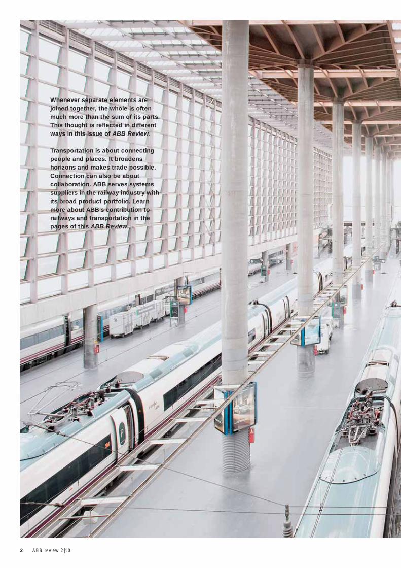
Whenever separate elements are joined together, the whole is often much more than the sum of its parts. This thought is reflected in different ways in this issue of ABB Review.
Transportation is about connecting people and places. It broadens horizons and makes trade possible.Connection can also be about collaboration. ABB serves systems suppliers in the railway industry with its broad product portfolio. Learn more about ABB’s contribution to railways and transportation in the pages of this ABB Review.
Contents
6
8
14
19
24
31
35
42
48
51
55
60
66
70
77
82
84
88
ABB, railways and transportation The company’s portfolio at a glance Rail solutions to the mobility challenge Interview with Michael Clausecker, Director General of UNIFE, and Jean-Luc Favre, CEO of ABB Sécheron and Head of ABB Rail Sector
On the fast trackABB is contributing to high-speed trains China’s rail revolutionABB technologies are helping transform China’s rail network into the fastest and most technologically advanced high-speed railway system in the worldGreener rail for IndiaABB is helping upgrade India’s railwaysSwitzerland by railSupplying traction power for the country’s major railway initiatives
Knowing the FACTSFACTS that enhance power quality in rail feeder systemsStatic converters, dynamic performanceProviding railway grids with the right frequencyBuilding on successFSK II outdoor vacuum circuit breakers make the connection for UK rail projectsTransforming ideas into movementABB vacuum cast coil dry transformers are doing excellent (under) ground work in Istanbul
Transforming suburban transportABB traction transformers helping to move millions of commutersA perfect fitABB’s powerful propulsion converters are compact, reliable and efficient, making them suitable for all vehicle designsStandardizing the traction motorABB’s innovative modular induction traction motor sets new heights in adaptability
Dedicated serviceABB offers a broad service palette for rail customers Dawn of a new ageABB’s electric vehicle charging units and smart grid technologies are supporting the vision of a new era of transportationPower from shoreABB shore-to-ship power solutions are cutting noise and greenhouse gas emissions by providing docked ships with shoreside electricityS3 – Speed, safety and savingsABB’s new ultra-fast earthing switch
Electrifying historyA long tradition in electric railway engineering
Trains in motion
Service and technology
Perpetual pioneering
Fixed infrastructure
Around the world
The railway perspective
3Contents

ABB review 2|10 4
Peter Terwiesch Chief Technology Officer ABB Ltd.
The freight sector is also experiencing exciting developments. In Europe especially, more and more countries are opening their rail freight markets to competition, leading to high levels of traffi c growth.
While not a train manufacturer as such, through its expertise in the power and automation sectors, ABB can offer many products and technologies to the railway industry. Electric railways are major consumers of electricity, and this consumption can fl uctuate strongly and in short time periods. ABB’s grid management technologies ensure power is delivered reliably while maintaining the stability of the supplying grids. To transfer power from grids to railways and to support the operation of both, ABB provides substations and components (includ-ing transformers, frequency converters, switchgear and FACTS devices). For the trains themselves, ABB’s offering includes traction transformers, switchgear, motors, converters and turbochargers. This issue of ABB Review looks at these product types.
ABB has grown its rail activities considerably in recent years, growing from the position of an outsider to a major supplier for several of the leading train manufacturers. To present a broader industry perspective, ABB Review interviewed Michael Clausecker, Director General of UNIFE (Union of European Rail Industries).
Besides supplying the rail sector, ABB plays a part in the broader spectrum of sustainable transportation and electrical mobility. Activities presented in this edition of ABB Review include charging technology for electric cars and a power supply to reduce the operating hours of ship engines while in port.
Enjoy your reading
Peter TerwieschChief Technology Offi cerABB Ltd.
Dear Reader,Mobility is a central aspect of our lives and activities. Whether we are commuting to work, travelling for business or taking a vacation, we depend on a reliable and affordable means of locomotion. Furthermore, transportation does not just affect us as individuals: The mecha-nized movement of goods has permitted the concentration of industry and hence modern manufacturing methods. Similarly, the existence of large cities depends on the ability to reliably and continuously supply them with food and other necessities.
Just as transportation helped create and develop many aspects of modern society, insuffi cient transportation can be detrimental to it. If goods cannot be delivered or people cannot reach their destination in a reasonable and predictable time, economic and other repercussions can be heart felt. This challenge is accentuated by ongoing developments: Growing urbanization is increasing strain on infrastructure and adding to congestion. At the same time, concerns over air quality, CO2, limited reserves of fossil fuels and also the spatial footprint of transportation are calling for cleaner and more effi cient solutions.
Railways are well positioned to meet these requirements. Within city areas, suburban railways and metros make an important contribution to relieving road congestion while offering a low carbon footprint, and if electrifi ed, zero emissions at point of delivery. Whereas cities such as London or Paris are expanding existing systems, many booming metropolises in developing countries are facing the challenge and opportunity of creating new systems from scratch.
High-speed trains can provide an attractive alternative to both driving and short-haul fl ights. They are relatively weather-independent and offer passengers a comfortable environment in which to relax or work. Whereas the fi rst generation of high-speed trains ran in Japan and Europe, they have considerably broadened their appeal. Soon high-speed trains will be running on fi ve continents.
Editorial
ABB and railways

5Editorial
6 ABB review 2|10
ABB, railways and transportation
11
8
2
3 4
12
1315
18
10
5
6
1
7
14
16
7ABB, railways and transportation
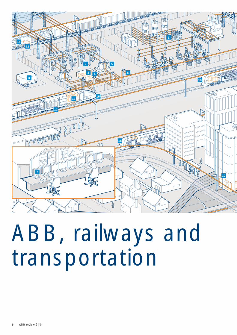
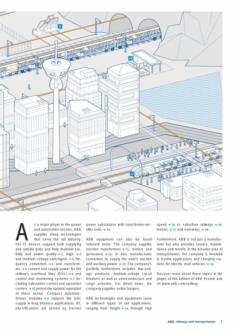
speed ➔ 15 to suburban railways ➔ 16, metros ➔ 17 and tramways ➔ 18.
Furthermore, ABB is not just a manufac-turer but also provides service, mainte-nance and retrofit. In the broader area of transportation, the company is involved in marine applications and charging sta-tions for electric road vehicles ➔ 19.
Discover more about these topics in the pages of this edition of ABB Review and on www.abb.com/railway.
power substations with transformer-rec-tifier units ➔ 10.
ABB equipment can also be found onboard trains. The company supplies traction transformers ➔ 11, motors and generators ➔ 12. It also manufactures converters to supply the train’s traction and auxiliary power ➔ 13. The company’s portfolio furthermore includes low-volt-age products, medium-voltage circuit breakers as well as semiconductors and surge arresters. For diesel trains, the company supplies turbochargers.
ABB technologies and equipment serve in different types of rail applications, ranging from freight ➔ 14 through high
A s a major player in the power and automation sectors, ABB supplies many technologies that serve the rail industry.
FACTS devices support both supplying and railside grids and help maintain sta-bility and power quality ➔ 1. High- ➔ 2 and medium-voltage switchgear ➔ 3, fre-quency converters ➔ 4 and transform-ers ➔ 5 convert and supply power for the railway’s overhead lines (OHL) ➔ 6 and control and monitoring systems ➔ 7 (in-cluding substation control and operation centers ➔ 8) permit the optimal operation of these assets. Compact autotrans-former modules ➔ 9 support the OHL supply in long distance applications. DC electrifications are served by traction
17
19
9
8 ABB review 2|10
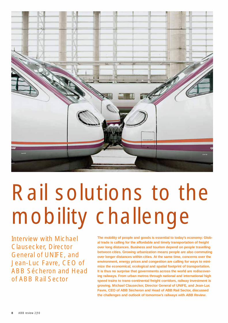
The mobility of people and goods is essential to today’s economy: Glob -al trade is calling for the affordable and timely transportation of freight over long distances. Business and tourism depend on people travelling between cities. Growing urbanization means people are also commuting over longer distances within cities. At the same time, con cerns over the environment, energy prices and congestion are calling for ways to mini-mize the economical, ecological and spatial footprint of transportation. It is thus no surprise that governments across the world are rediscover-ing railways. From urban metros through national and international high speed trains to trans-continental freight corridors, railway investment is growing. Michael Clausecker, Director General of UNIFE, and Jean-Luc Favre, CEO of ABB Sécheron and Head of ABB Rail Sector, discussed the challenges and outlook of tomorrow’s railways with ABB Review.
Interview with Michael Clausecker, Director General of UNIFE, and Jean-Luc Favre, CEO of ABB Sécheron and Head of ABB Rail Sector
Rail solutions to the mobility challenge
9Rail solutions to the mobility challenge
In the case of India, it is difficult to fore-see when high-speed will become a real-ity. The main developments there today are in metros and urban rail.
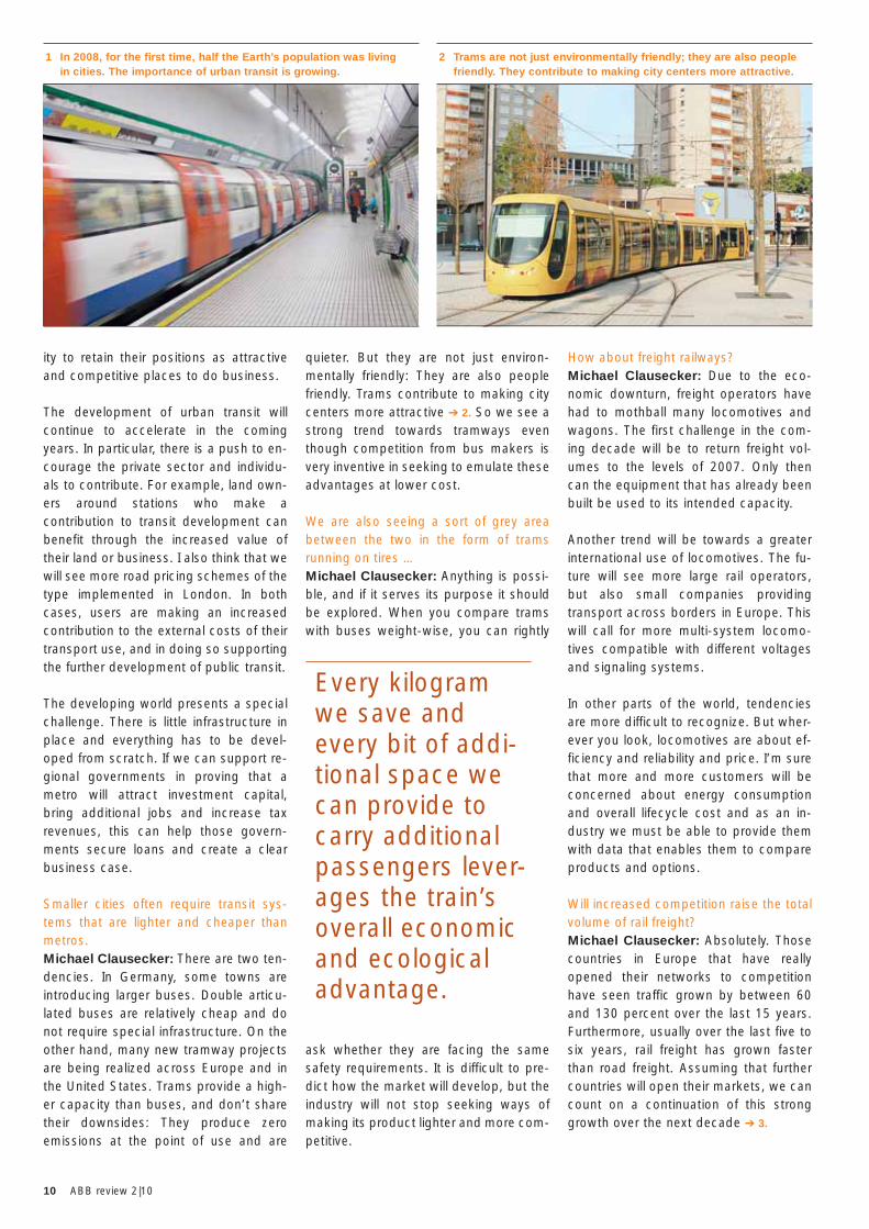
Jean-Luc FavreWe have to consider the effect of de-mography. Most probably there will be nine billion people on the Earth by 2050. There is also a strong trend towards ur-banization. In 2008, for the first time, half of the Earth’s population was living in cit-ies. There is a clear case for sustainable transportation and rail can deliver that ➔ 1.
In China, huge investments are going on in freight and passenger rail and also electrification projects. The high-speed network is growing at an astonishing rate. For ABB, China has been the fast-est growing market over the last two to three years. Europe is also a strong mar-ket, but when it comes to network growth and investments in new locomotives and trains, it is in China that we are seeing the most significant developments.
In India too, we are starting to see proj-ects move forwards. Freight corridors are being created – freight can be moved more efficiently in dedicated corridors. However, the fastest growing market in India is metros. The government wants all cities above three million to have a metro. There are huge projects in Bangalore, Kolkata, Mumbai and Delhi. We are also expecting a high-speed market to emerge there in the next five to ten years.
You have both mentioned urban trans-portation. What are the main trends there?Michael Clausecker: Large cities are becoming even larger, and with them the importance of transportation. It is be-coming more and more difficult for citi-zens to get to and from work in the morn-ing and evening. Clearly public transport is an efficient way to address that chal-lenge. It is no surprise that we are seeing many major cities implementing transit systems, in particular in China. But even cities such as Paris and London are struggling with traffic congestion and re-alize that they need to add transit capac-
What are the major challenges and de-velopments that the railway industry will face in the next decade?Michael Clausecker: Let us start with high speed. Today, major projects are underway in France, Spain and Great Britain. In the United States too, the de-bate about high-speed lines has finally begun. Russia is making progress on the Moscow to St. Petersburg project. The Chinese are investing more than anybody else and building thousands of kilome-ters of high-speed lines. The sector is experiencing massive growth.
Where do you see future priorities?Michael Clausecker: The vast majority of high-speed connections today are na-tional: in France, Germany, Spain etc. There are of course also international services, such as Eurostar or Thalys, but the further development of high speed in Europe will need to have a more interna-tional focus.
For governments, the key issue for the next 10 years will be investment in infra-structure. I believe we will see growing
willingness to invest in rail, and also more innovation in financing such schemes. This can include public-private partner-ships and build, operate and transfer models.
And in other parts of the world, such as Eastern Europe or India?Michael Clausecker: I hope we will see the construction of the first high-speed line in Eastern Europe in the next decade. There is already a plan to start building a high-speed line in Poland by 2014.
Mr. Clausecker, could you briefly intro-duce UNIFE?Michael Clausecker: UNIFE 1 was set up to support railway equipment manu-facturers in Europe. It does this:1 By seeking technical harmonization
and regulation of railway systems.2 By lobbying for policies that are
favorable to the development of the rail segment.
3 By launching and supporting pro-grams to help member companies conduct research jointly with railway operators and by facilitating the associated application for European funds.
4 By ensuring the superior quality of the products of its member companies throughout the entire value chain, using its quality-management pro-gram, IRIS 2.
UNIFE is funded by its members, who are all private European companies sup-plying to railways across the world. The organization also has associate mem-bers (mostly national rail supply associa-tions). There are about 70 companies in UNIFE and almost 1000 in its national associations. UNIFE thus speaks for the largest part of the European rail indus-try.
The future will see more cross-border freight transport in Europe. This will call for more multi-system locomo-tives compatible to different voltages and signaling sys-tems.
Footnotes1 UNIFE: Union des Industries Ferroviaires Euro-
péennes, (Union of European Rail Industries)2 IRIS: International Railway Industry Standard.
See also inset 7 on page 23.
10 ABB review 2|10
How about freight railways?Michael Clausecker: Due to the eco-nomic downturn, freight operators have had to mothball many locomotives and wagons. The first challenge in the com-ing decade will be to return freight vol-umes to the levels of 2007. Only then can the equipment that has already been built be used to its intended capacity.
Another trend will be towards a greater international use of locomotives. The fu-ture will see more large rail operators, but also small companies providing transport across borders in Europe. This will call for more multi-system locomo-tives compatible with different voltages and signaling systems.
In other parts of the world, tendencies are more difficult to recognize. But wher-ever you look, locomotives are about ef-ficiency and reliability and price. I’m sure that more and more customers will be concerned about energy consumption and overall lifecycle cost and as an in-dustry we must be able to provide them with data that enables them to compare products and options.
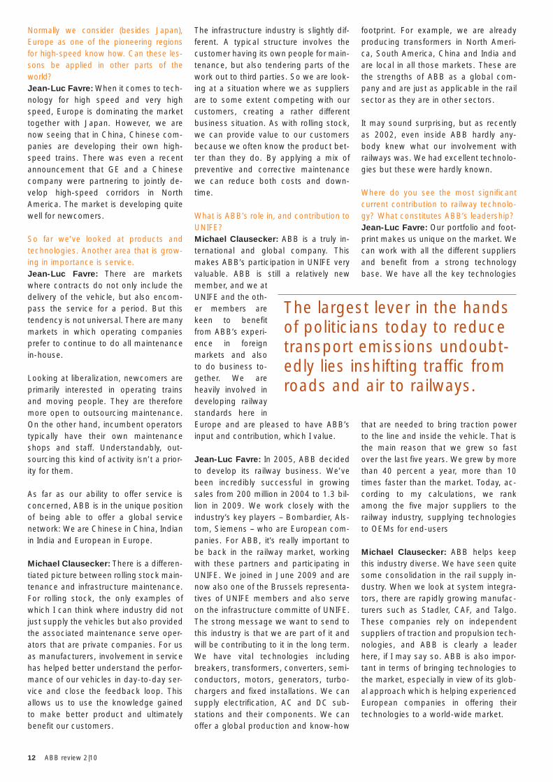
Will increased competition raise the total volume of rail freight?Michael Clausecker: Absolutely. Those countries in Europe that have really opened their networks to competition have seen traffic grown by between 60 and 130 percent over the last 15 years. Furthermore, usually over the last five to six years, rail freight has grown faster than road freight. Assuming that further countries will open their markets, we can count on a continuation of this strong growth over the next decade ➔ 3.
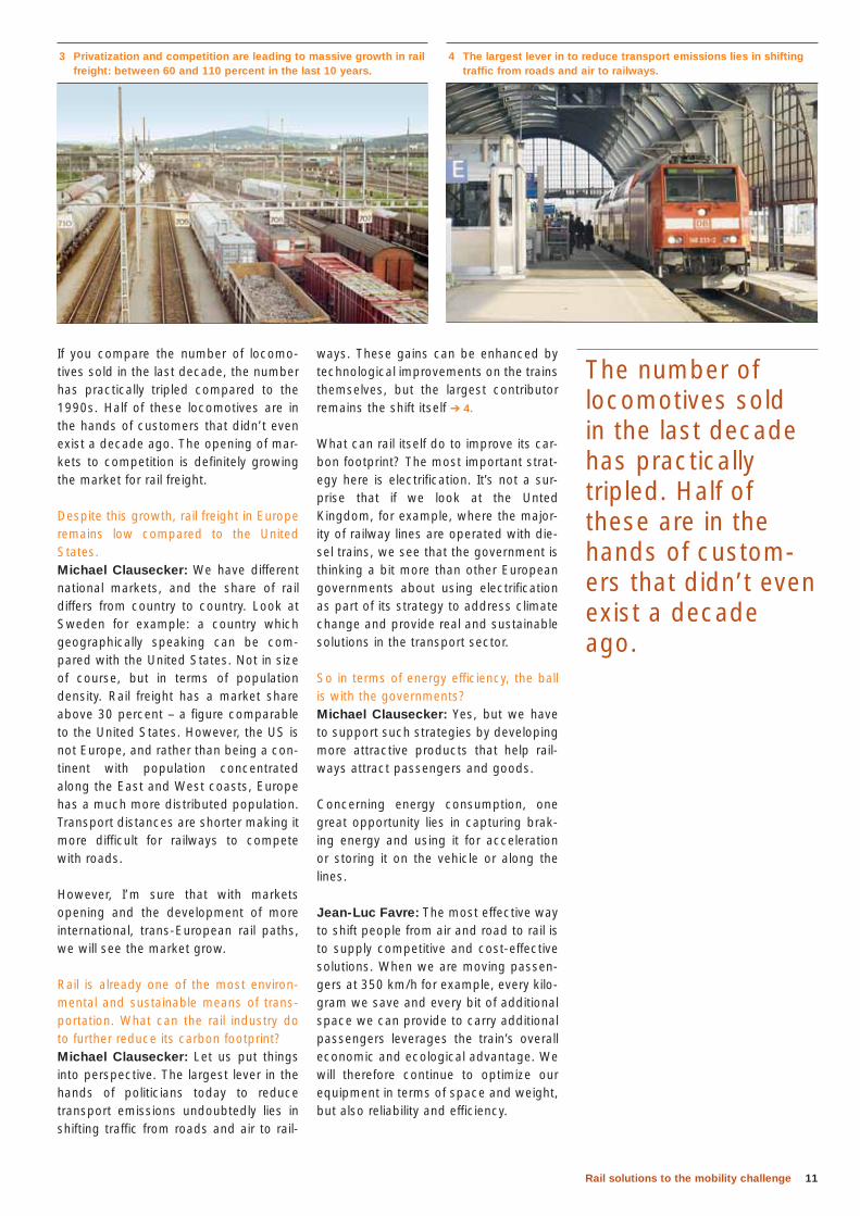
quieter. But they are not just environ-mentally friendly: They are also people friendly. Trams contribute to making city centers more attractive ➔ 2. So we see a strong trend towards tramways even though competition from bus makers is very inventive in seeking to emulate these advantages at lower cost.
We are also seeing a sort of grey area between the two in the form of trams running on tires …Michael Clausecker: Anything is possi-ble, and if it serves its purpose it should be explored. When you compare trams with buses weight-wise, you can rightly
ask whether they are facing the same safety requirements. It is difficult to pre-dict how the market will develop, but the industry will not stop seeking ways of making its product lighter and more com-petitive.
ity to retain their positions as attractive and competitive places to do business.
The development of urban transit will continue to accelerate in the coming years. In particular, there is a push to en-courage the private sector and individu-als to contribute. For example, land own-ers around stations who make a contribution to transit development can benefit through the increased value of their land or business. I also think that we will see more road pricing schemes of the type implemented in London. In both cases, users are making an increased contribution to the external costs of their transport use, and in doing so supporting the further development of public transit.
The developing world presents a special challenge. There is little infrastructure in place and everything has to be devel-oped from scratch. If we can support re-gional governments in proving that a metro will attract investment capital, bring additional jobs and increase tax revenues, this can help those govern-ments secure loans and create a clear business case. Smaller cities often require transit sys-tems that are lighter and cheaper than metros.Michael Clausecker: There are two ten-dencies. In Germany, some towns are introducing larger buses. Double articu-lated buses are relatively cheap and do not require special infrastructure. On the other hand, many new tramway projects are being realized across Europe and in the United States. Trams provide a high-er capacity than buses, and don’t share their downsides: They produce zero emissions at the point of use and are
1 In 2008, for the first time, half the Earth’s population was living in cities. The importance of urban transit is growing.
2 Trams are not just environmentally friendly; they are also people friendly. They contribute to making city centers more attractive.
Every kilogram we save and every bit of addi-tional space we can provide to carry additional passengers lever-ages the train’s overall economic and ecological advantage.
11Rail solutions to the mobility challenge
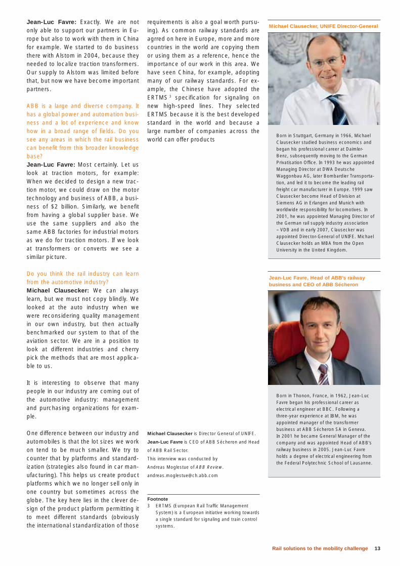
ways. These gains can be enhanced by technological improvements on the trains themselves, but the largest contributor remains the shift itself ➔ 4.
What can rail itself do to improve its car-bon footprint? The most important strat-egy here is electrification. It’s not a sur-prise that if we look at the Unted Kingdom, for example, where the major-ity of railway lines are operated with die-sel trains, we see that the government is thinking a bit more than other European governments about using electrification as part of its strategy to address climate change and provide real and sustainable solutions in the transport sector.
So in terms of energy efficiency, the ball is with the governments?Michael Clausecker: Yes, but we have to support such strategies by developing more attractive products that help rail-ways attract passengers and goods.
Concerning energy consumption, one great opportunity lies in capturing brak-ing energy and using it for acceleration or storing it on the vehicle or along the lines.
Jean-Luc Favre: The most effective way to shift people from air and road to rail is to supply competitive and cost-effective solutions. When we are moving passen-gers at 350 km/h for example, every kilo-gram we save and every bit of additional space we can provide to carry additional passengers leverages the train’s overall economic and ecological advantage. We will therefore continue to optimize our equipment in terms of space and weight, but also reliability and efficiency.
If you compare the number of locomo-tives sold in the last decade, the number has practically tripled compared to the 1990s. Half of these locomotives are in the hands of customers that didn’t even exist a decade ago. The opening of mar-kets to competition is definitely growing the market for rail freight.
Despite this growth, rail freight in Europe remains low compared to the United States. Michael Clausecker: We have different national markets, and the share of rail differs from country to country. Look at Sweden for example: a country which geographically speaking can be com-pared with the United States. Not in size of course, but in terms of population density. Rail freight has a market share above 30 percent – a figure comparable to the United States. However, the US is not Europe, and rather than being a con-tinent with population concentrated along the East and West coasts, Europe has a much more distributed population. Transport distances are shorter making it more difficult for railways to compete with roads.
However, I’m sure that with markets opening and the development of more international, trans-European rail paths, we will see the market grow.
Rail is already one of the most environ-mental and sustainable means of trans-portation. What can the rail industry do to further reduce its carbon footprint? Michael Clausecker: Let us put things into perspective. The largest lever in the hands of politicians today to reduce transport emissions undoubtedly lies in shifting traffic from roads and air to rail-
3 Privatization and competition are leading to massive growth in rail freight: between 60 and 110 percent in the last 10 years.
4 The largest lever in to reduce transport emissions lies in shifting traffic from roads and air to railways.
The number of locomotives sold in the last decade has practically tripled. Half of these are in the hands of custom-ers that didn’t even exist a decade ago.
12 ABB review 2|10
footprint. For example, we are already producing transformers in North Ameri-ca, South America, China and India and are local in all those markets. These are the strengths of ABB as a global com-pany and are just as applicable in the rail sector as they are in other sectors.
It may sound surprising, but as recently as 2002, even inside ABB hardly any-body knew what our involvement with railways was. We had excellent technolo-gies but these were hardly known.
Where do you see the most significant current contribution to railway technolo-gy? What constitutes ABB’s leadership?Jean-Luc Favre: Our portfolio and foot-print makes us unique on the market. We can work with all the different suppliers and benefit from a strong technology base. We have all the key technologies
that are needed to bring traction power to the line and inside the vehicle. That is the main reason that we grew so fast over the last five years. We grew by more than 40 percent a year, more than 10 times faster than the market. Today, ac-cording to my calculations, we rank among the five major suppliers to the railway industry, supplying technologies to OEMs for end-users
Michael Clausecker: ABB helps keep this industry diverse. We have seen quite some consolidation in the rail supply in-dustry. When we look at system integra-tors, there are rapidly growing manufac-turers such as Stadler, CAF, and Talgo. These companies rely on independent suppliers of traction and propulsion tech-nologies, and ABB is clearly a leader here, if I may say so. ABB is also impor-tant in terms of bringing technologies to the market, especially in view of its glob-al approach which is helping experienced European companies in offering their technologies to a world-wide market.
The infrastructure industry is slightly dif-ferent. A typical structure involves the customer having its own people for main-tenance, but also tendering parts of the work out to third parties. So we are look-ing at a situation where we as suppliers are to some extent competing with our customers, creating a rather different business situation. As with rolling stock, we can provide value to our customers because we often know the product bet-ter than they do. By applying a mix of preventive and corrective maintenance we can reduce both costs and down-time.
What is ABB’s role in, and contribution to UNIFE? Michael Clausecker: ABB is a truly in-ternational and global company. This makes ABB’s participation in UNIFE very valuable. ABB is still a relatively new member, and we at UNIFE and the oth-er members are keen to benefit from ABB’s experi-ence in foreign markets and also to do business to-gether. We are heavily involved in developing railway standards here in Europe and are pleased to have ABB’s input and contribution, which I value.
Jean-Luc Favre: In 2005, ABB decided to develop its railway business. We’ve been incredibly successful in growing sales from 200 million in 2004 to 1.3 bil-lion in 2009. We work closely with the industry’s key players – Bombardier, Als-tom, Siemens – who are European com-panies. For ABB, it’s really important to be back in the railway market, working with these partners and participating in UNIFE. We joined in June 2009 and are now also one of the Brussels representa-tives of UNIFE members and also serve on the infrastructure committe of UNIFE. The strong message we want to send to this industry is that we are part of it and will be contributing to it in the long term. We have vital technologies including breakers, transformers, converters, semi-conductors, motors, generators, turbo-chargers and fixed installations. We can supply electrification, AC and DC sub-stations and their components. We can offer a global production and know-how
Normally we consider (besides Japan), Europe as one of the pioneering regions for high-speed know how. Can these les-sons be applied in other parts of the world? Jean-Luc Favre: When it comes to tech-nology for high speed and very high speed, Europe is dominating the market together with Japan. However, we are now seeing that in China, Chinese com-panies are developing their own high-speed trains. There was even a recent announcement that GE and a Chinese company were partnering to jointly de-velop high-speed corridors in North America. The market is developing quite well for newcomers.
So far we’ve looked at products and technologies. Another area that is grow-ing in importance is service.Jean-Luc Favre: There are markets where contracts do not only include the delivery of the vehicle, but also encom-pass the service for a period. But this tendency is not universal. There are many markets in which operating companies prefer to continue to do all maintenance in-house.
Looking at liberalization, newcomers are primarily interested in operating trains and moving people. They are therefore more open to outsourcing maintenance. On the other hand, incumbent operators typically have their own maintenance shops and staff. Understandably, out-sourcing this kind of activity isn’t a prior-ity for them.
As far as our ability to offer service is concerned, ABB is in the unique position of being able to offer a global service network: We are Chinese in China, Indian in India and European in Europe.
Michael Clausecker: There is a differen-tiated picture between rolling stock main-tenance and infrastructure maintenance. For rolling stock, the only examples of which I can think where industry did not just supply the vehicles but also provided the associated maintenance serve oper-ators that are private companies. For us as manufacturers, involvement in service has helped better understand the perfor-mance of our vehicles in day-to-day ser-vice and close the feedback loop. This allows us to use the knowledge gained to make better product and ultimately benefit our customers.
The largest lever in the hands of politicians today to reduce transport emissions undoubt-edly lies inshifting traffic from roads and air to railways.
13Rail solutions to the mobility challenge
requirements is also a goal worth pursu-ing). As common railway standards are agrred on here in Europe, more and more countries in the world are copying them or using them as a reference, hence the importance of our work in this area. We have seen China, for example, adopting many of our railway standards. For ex-ample, the Chinese have adopted the ERTMS 3 specification for signaling on new high-speed lines. They selected ERTMS because it is the best developed standard in the world and because a large number of companies across the world can offer products
Michael Clausecker is Director General of UNIFE.
Jean-Luc Favre is CEO of ABB Sécheron and Head
of ABB Rail Sector.
This interview was conducted by
Andreas Moglestue of ABB Review.
Footnote3 ERTMS (European Rail Traffic Management
System) is a European initiative working towards a single standard for signaling and train control systems.
Jean-Luc Favre: Exactly. We are not only able to support our partners in Eu-rope but also to work with them in China for example. We started to do business there with Alstom in 2004, because they needed to localize traction transformers. Our supply to Alstom was limited before that, but now we have become important partners.
ABB is a large and diverse company. It has a global power and automation busi-ness and a lot of experience and know how in a broad range of fields. Do you see any areas in which the rail business can benefit from this broader knowledge base? Jean-Luc Favre: Most certainly. Let us look at traction motors, for example: When we decided to design a new trac-tion motor, we could draw on the motor technology and business of ABB, a busi-ness of $2 billion. Similarly, we benefit from having a global supplier base. We use the same suppliers and also the same ABB factories for industrial motors as we do for traction motors. If we look at transformers or converts we see a similar picture.
Do you think the rail industry can learn from the automotive industry?Michael Clausecker: We can always learn, but we must not copy blindly. We looked at the auto industry when we were reconsidering quality management in our own industry, but then actually benchmarked our system to that of the aviation sector. We are in a position to look at different industries and cherry pick the methods that are most applica-ble to us.
It is interesting to observe that many people in our industry are coming out of the automotive industry: management and purchasing organizations for exam-ple.
One difference between our industry and automobiles is that the lot sizes we work on tend to be much smaller. We try to counter that by platforms and standard-ization (strategies also found in car man-ufacturing). This helps us create product platforms which we no longer sell only in one country but sometimes across the globe. The key here lies in the clever de-sign of the product platform permitting it to meet different standards (obviously the international standardization of those
Born in Stuttgart, Germany in 1966, Michael Clausecker studied business economics and began his professional career at Daimler-Benz, subsequently moving to the German Privatisation Office. In 1993 he was appointed Managing Director at DWA Deutsche Waggonbau AG, later Bombardier Transporta-tion, and led it to become the leading rail freight car manufacturer in Europe. 1999 saw Clausecker become Head of Division at Siemens AG in Erlangen and Munich with worldwide responsibility for locomotives. In 2001, he was appointed Managing Director of the German rail supply industry association – VDB and in early 2007, Clausecker was appointed Director-General of UNIFE. Michael Clausecker holds an MBA from the Open University in the United Kingdom.
Michael Clausecker, UNIFE Director-General
Born in Thonon, France, in 1962, Jean-Luc Favre began his professional career as electrical engineer at BBC. Following a three-year experience at IBM, he was appointed manager of the transformer business at ABB Sécheron SA in Geneva. In 2001 he became General Manager of the company and was appointed Head of ABB’s railway business in 2005. Jean-Luc Favre holds a degree of electrical engineering from the Federal Polytechnic School of Lausanne.
Jean-Luc Favre, Head of ABB’s railway business and CEO of ABB Sécheron
14 ABB review 2|10
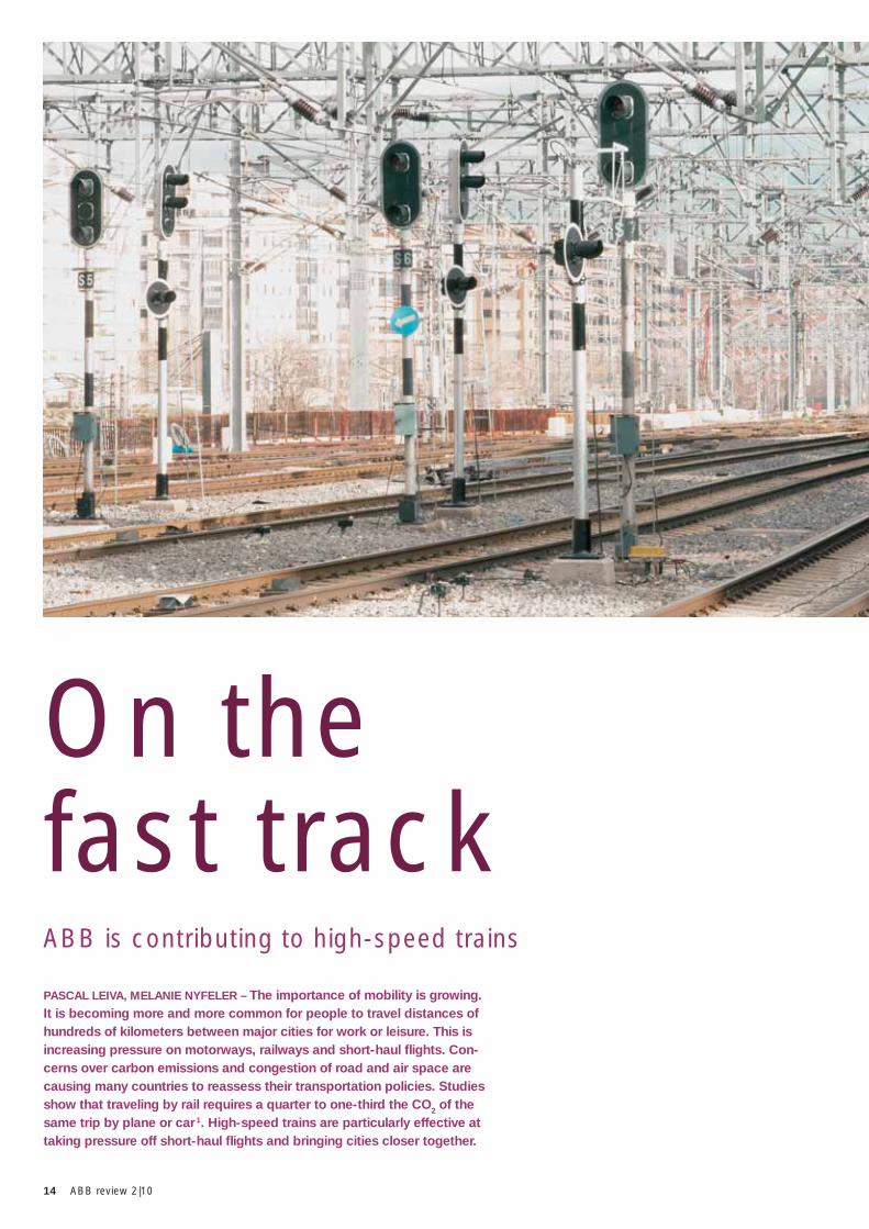
PASCAL LEIVA, MELANIE NYFELER – The importance of mobility is growing. It is becoming more and more common for people to travel distances of hundreds of kilometers between major cities for work or leisure. This is increasing pressure on motorways, railways and short-haul fl ights. Con-cerns over carbon emissions and congestion of road and air space are causing many countries to reassess their transportation policies. Studies show that traveling by rail requires a quarter to one-third the CO2 of the same trip by plane or car 1. High-speed trains are particularly effective at taking pressure off short-haul fl ights and bringing cities closer together.
ABB is contributing to high-speed trains
On the fast track
15On the fast track
cord of 331 km/h. Notably, the trains and catenary used were closely based on equipment that was used in everyday service. This demonstrated the safety margins of the technology and indicated the feasibility of the commercial opera-tion of high-speed trains.
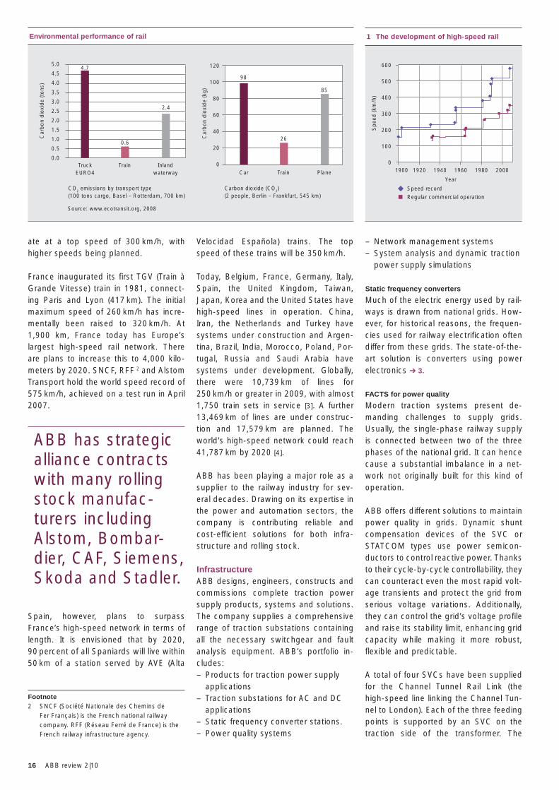
Day-to-day speeds, however, remained much lower, with the fastest trains operating at top speeds of around 160 km/h ➔ 1. The first commercial train that can be considered high speed in the modern sense is the Japanese Shink-ansen. It was inaugurated in 1964 on the 515 km line between Tokyo and Osaka, and initially operated at a top speed of 200 km/h (increased to 210 km/h the fol-lowing year). This route is still the world’s busiest high-speed corridor, carrying more than 360,000 passengers every weekday. Today, Shinkansen trains oper-
– Use of train sets rather than conven-tional locomotive and cars formations. These offer better power-to-weight ratios, aerodynamic conditions, reliability, safety, etc.
– Use of dedicated high-speed lines on at least part of the journey. Such lines are built to sustain high speeds (through their choice of transverse sections, track quality, catenary, power supply, special environmental conditions, etc.) However, one strength of high-speed trains is that they can also operate on conventional lines with certain restrictions [2], so reducing the necessary investment or permitting a phased introduction.
– Use of advanced signaling systems, including in-cab signaling.
Development of high speed trainsAs early as 1903, a speed of 210 km/h was attained using an experimental three-phase electrification in Germany, demonstrating the aptitude of electric traction for high speeds. In 1955, a se-ries of tests in France culminated in a re-
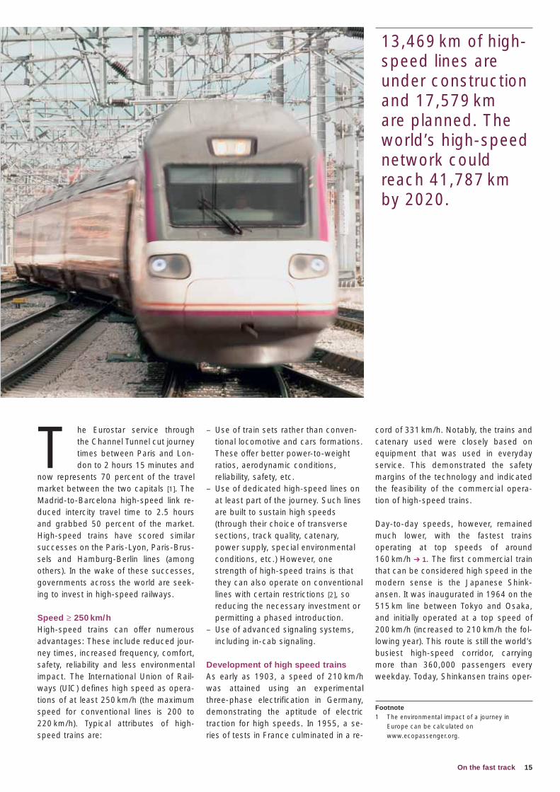
T he Eurostar service through the Channel Tunnel cut journey times between Paris and Lon-don to 2 hours 15 minutes and
now represents 70 percent of the travel market between the two capitals [1]. The Madrid-to-Barcelona high-speed link re-duced intercity travel time to 2.5 hours and grabbed 50 percent of the market. High-speed trains have scored similar successes on the Paris-Lyon, Paris-Brus-sels and Hamburg-Berlin lines (among others). In the wake of these successes, governments across the world are seek-ing to invest in high-speed railways.
Speed ≥ 250 km/hHigh-speed trains can offer numerous advantages: These include reduced jour-ney times, increased frequency, comfort, safety, reliability and less environmental impact. The International Union of Rail-ways (UIC) defines high speed as opera-tions of at least 250 km/h (the maximum speed for conventional lines is 200 to 220 km/h). Typical attributes of high-speed trains are:
Footnote1 The environmental impact of a journey in Europe can be calculated on www.ecopassenger.org.
13,469 km of high-speed lines are under construction and 17,579 km are planned. The world’s high-speed network could reach 41,787 km by 2020.
16 ABB review 2|10
– Network management systems – System analysis and dynamic traction
power supply simulations
Static frequency converters
Much of the electric energy used by rail-ways is drawn from national grids. How-ever, for historical reasons, the frequen-cies used for railway electrification often differ from these grids. The state-of-the-art solution is converters using power electronics ➔ 3.
FACTS for power quality
Modern traction systems present de-manding challenges to supply grids. Usually, the single-phase railway supply is connected between two of the three phases of the national grid. It can hence cause a substantial imbalance in a net-work not originally built for this kind of operation.
ABB offers different solutions to maintain power quality in grids. Dynamic shunt compensation devices of the SVC or STATCOM types use power semicon-ductors to control reactive power. Thanks to their cycle-by-cycle controllability, they can counteract even the most rapid volt-age transients and protect the grid from serious voltage variations. Additionally, they can control the grid’s voltage profile and raise its stability limit, enhancing grid capacity while making it more robust, flexible and predictable.
A total of four SVCs have been supplied for the Channel Tunnel Rail Link (the high-speed line linking the Channel Tun-nel to London). Each of the three feeding points is supported by an SVC on the traction side of the transformer. The
Velocidad Española) trains. The top speed of these trains will be 350 km/h.
Today, Belgium, France, Germany, Italy, Spain, the United Kingdom, Taiwan, Japan, Korea and the United States have high-speed lines in operation. China, Iran, the Netherlands and Turkey have systems under construction and Argen-tina, Brazil, India, Morocco, Poland, Por-tugal, Russia and Saudi Arabia have systems under development. Globally, there were 10,739 km of lines for 250 km/h or greater in 2009, with almost 1,750 train sets in service [3]. A further 13,469 km of lines are under construc-tion and 17,579 km are planned. The world’s high-speed network could reach 41,787 km by 2020 [4].
ABB has been playing a major role as a supplier to the railway industry for sev-eral decades. Drawing on its expertise in the power and automation sectors, the company is contributing reliable and cost-efficient solutions for both infra-structure and rolling stock.
InfrastructureABB designs, engineers, constructs and commissions complete traction power supply products, systems and solutions. The company supplies a comprehensive range of traction substations containing all the necessary switchgear and fault analysis equipment. ABB’s portfolio in-cludes:– Products for traction power supply
applications – Traction substations for AC and DC
applications – Static frequency converter stations. – Power quality systems
ate at a top speed of 300 km/h, with higher speeds being planned.
France inaugurated its first TGV (Train à Grande Vitesse) train in 1981, connect-ing Paris and Lyon (417 km). The initial maximum speed of 260 km/h has incre-mentally been raised to 320 km/h. At 1,900 km, France today has Europe’s largest high-speed rail network. There are plans to increase this to 4,000 kilo-meters by 2020. SNCF, RFF 2 and Alstom Transport hold the world speed record of 575 km/h, achieved on a test run in April 2007.
Spain, however, plans to surpass France’s high-speed network in terms of length. It is envisioned that by 2020, 90 percent of all Spaniards will live within 50 km of a station served by AVE (Alta
ABB has strategic alliance contracts with many rolling stock manufac-turers including Alstom, Bombar-dier, CAF, Siemens, Skoda and Stadler.
Footnote2 SNCF (Société Nationale des Chemins de
Fer Français) is the French national railway company. RFF (Réseau Ferré de France) is the French railway infrastructure agency.
1 The development of high-speed rail
Year
600
500
400
300
200
100
0
Sp
eed
(km
/h)
1900 1920 1940 1960 1980 2000
Speed record
Regular commercial operation
Environmental performance of rail
TruckEURO4 Car
CO2 emissions by transport type(100 tons cargo, Basel – Rotterdam, 700 km)
Carbon dioxide (CO2)(2 people, Berlin – Frankfurt, 545 km)
Source: www.ecotransit.org, 2008
Inlandwaterway Plane
TrainTrain
5.0
4.5
4.0
3.5
3.0
2.5
2.0
1.5
1.0
0.5
0.0
120
100
80
60
40
20
0
Car
bon
dio
xid
e (t
ons)
Car
bon
dio
xid
e (k
g)
4.7
0.6
2.4
98
26
85
17On the fast track
– It must be compact in terms of size and weight.
– Many transformers must deal with multiple voltages and frequencies due to the different electrification systems used across Europe (and sometimes within one country).
An ABB traction transformer was used on the record-breaking AGV train that at-tained 575km/h in April 2007, ABB is supplying traction transformers for the high-speed trains of Alstom (AGV) ➔ 4, Siemens (Velaro) ➔ 5 and Bombardier (ZEFIRO) ➔ 6.
The evolution of market requirements has led to the following situation: While “classical” European high-speed trains such as the ICE-1 and the TGV are pow-ered by dedicated power units at the ends of the train, the new generation of high-speed trains such as the Velaro and the AGV use traction distributed along their entire lengths. This per-mits a better use of adhesion due to the lower power required per axle. Fur-thermore, by placing the complete trac-tion chain under floor (including trans-formers, converters, motors and control equipment), practically the full length of the train is available for passengers (a
fourth SVC is used for load balancing. This technology is discussed more fully in “Knowing the FACTS” on page 35 of this issue of ABB Review.
Transformers
A high-speed train can draw consider-able power, especially while accelerating. Transformers convert the grid voltage to the correct line voltage for the rail-way ➔ 2.
Rolling stockManufacturers of high-speed trains are continuously refining their designs to meet rising demands in terms of perfor-mance, efficiency and reliability, and are placing similarly high demands on their suppliers. In recent years, ABB has ex-tended its expertise for traction trans-formers and is now the world leader in this field. The company has strategic alli-ance contracts with the rolling stock manufacturers including Alstom, Ansaldo Breda, Bombardier, CAF, Siemens, Sko-da and Stadler. Various types of traction transformers have been designed and delivered to practically all railway integra-tors and are in use all over the world.
Traction transformers
A traction transformer is a key compo-nent of a train’s onboard traction chain. Special criteria it must fulfill include:– It is a single transfer point for energy
between catenary and motors, and must therefore meet high reliability levels.
3 Static frequency converter projects
ABB is currently realizing the world’s largest and most powerful static converter system in conjunction with E.ON Kraftwerke GmbH of Germany. This converter system is rated at 413 MW and connects the 50 Hz national grid to the 16.7 Hz railway grid. The completion of the order is scheduled for 2011. Other static frequency converters supplied to German Railways include the eight 15 MW units at Limburg supplying the high speed line between Cologne (Köln) and Frankfurt am Main. Converters have also been supplied to the Austrian and Swiss railway operators.
For more information on these projects, please see “Static converters, dynamic performance” on page 42 of this issue of ABB Review.
ABB won the contract to supply all trans- formers for the Barcelona-Figueras section of the AVE line that will connect Madrid via Zaragoza and Barcelona to the French border. These transformers will be located in the substations along this section at Baro de Viver, Riudarenes and Santa Llogaia.
The contract was awarded by the SILFRA-SUD consortium, made up of Siemens and Inabensa, and consisted of four transformers of 60 MVA, 405 / 27.5 kV produced in ABB’s Cordoba factory and two transformers of 60 MVA, 220 / 27.5 kV made in ABB’s Bilbao factory, Spain.
Since 1990, ABB has supplied a total of 85 transformers for high-speed lines all over Spain, and it is also the selected supplier through a frame agreement signed with ADIF (the Spanish rail infrastructure administrator), which covers the supply of traction transform-ers until 2014 and includes 52 additional units.
2 Transformers for Spanish high-speed lines
gain of up to 20 percent). The transform-ers ABB is supplying for both AGV and Velaro are compatible with Europe’s main railway voltages and frequencies.
Traction converters
ABB has supplied traction converters for the retrofit project of DB’s (German Rail-ways) ICE-1. This is discussed in the in-set on page 76.
Motors
Together with Bombardier, Ansaldo Bre-da, Alstom, and Firema, ABB is part of the Trevi Consortium supplying the ETR 500 to Trenitalia (Italian railways). Trenitalia chose to electrify its new high-speed lines at 25 kV AC rather than the 3 kV DC used on the classic network. Therefore, between 2006 and 2008 the
3 kV ETR 500 fleet was upgraded for dual voltage capability. In February 2006 the trains commenced regular service at a commercial top speed of 300 km/h on the new high-speed lines connecting Milan to Turin, Florence, Rome and Na-
An ABB traction transformer was used on the record-breaking AGV train that attained 575 km/h in April 2007.
18 ABB review 2|10
Pascal Leiva
ABB Sécheron Ltd.
Geneva, Switzerland
Melanie Nyfeler
ABB Switzerland, Communications
Baden, Switzerland
References[1] Crumley, B. (2000, June 8) Working on the
Railroad, Time Global Business.[2] Glover, J. (November 2009) Global insights into
high speed rail, Modern Railways.[3] UIC, (January 2009) High speed rail, Fast track
to sustainable mobility.[4] Barron, I. (updated 14 June 2009) High speed
lines in the World, UIC high speed department.[5] Wolf, A. (April 2009) Demand for high speed
trains continues to rise, International Railway Journal.
and the replacement of first-generation high-speed trains will commence soon in France and Germany. Developments in the eastern European, South American and North African markets are also likely to lead to growth in the high-speed market. In the United States, President Barack Obama has vowed to spend $13 billion over five years to develop high-speed rail links between major cit-ies. The outlook for high-speed rail is bright.
ples. ABB delivered more than 280 trac-tion motors for the ETR 500. For more information on ABB’s traction motors, see “Standardizing the traction motor” on page 66 of this edition of ABB Review.
Fast growing market Looking at present orders and deliveries, 2,500 high-speed trains capable of run-ning at over 200 km/h will be in operation
worldwide by the end of 2010. China alone has 10,000 km of new high-speed lines under construction and an addition-al 3,000 km are planned [4]. The western European market is also still growing,
2,500 high-speed trains capable of running at over 200 km/h will be in operation world-wide by the end of 2010.
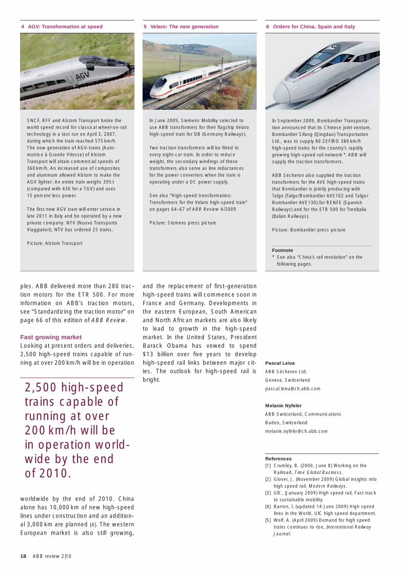
4 AGV: Transformation at speed
SNCF, RFF and Alstom Transport broke the world speed record for classical wheel-on-rail technology in a test run on April 3, 2007, during which the train reached 575 km/h. The new generation of AGV-trains (Auto-motrice à Grande Vitesse) of Alstom Transport will attain commercial speeds of 360 km/h. An increased use of composites and aluminum allowed Alstom to make the AGV lighter: An entire train weighs 395 t (compared with 430 for a TGV) and uses 15 percent less power.
The first new AGV train will enter service in late 2011 in Italy and be operated by a new private company: NTV (Nuovo Transporto Viaggiatori). NTV has ordered 25 trains.
Picture: Alstom Transport
5 Velaro: The new generation
In June 2009, Siemens Mobility selected to use ABB transformers for their flagship Velaro high-speed train for DB (Germany Railways).
Two traction transformers will be fitted to every eight-car train. In order to reduce weight, the secondary windings of these transformers also serve as line inductances for the power converters when the train is operating under a DC power supply.
See also “High-speed transformation: Transformers for the Velaro high-speed train” on pages 64–67 of ABB Review 4/2009.
Picture: Siemens press picture
6 Orders for China, Spain and Italy
In September 2009, Bombardier Transporta-tion announced that its Chinese joint venture, Bombardier Sifang (Qingdao) Transportation Ltd., was to supply 80 ZEFIRO 380 km/h high-speed trains for the country’s rapidly growing high-speed rail network *. ABB will supply the traction transformers.
ABB Sécheron also supplied the traction transformers for the AVE high-speed trains that Bombardier is jointly producing with Talgo (Talgo/Bombardier AVE102 and Talgo/Bombardier AVE130) for RENFE (Spanish Railways) and for the ETR 500 for TrenItalia (Italian Railways).
Picture: Bombardier press picture
Footnote* See also “China’s rail revolution” on the following pages.
19China’s rail revolution
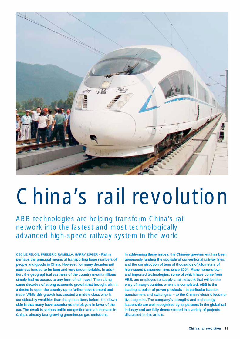
In addressing these issues, the Chinese government has been generously funding the upgrade of conventional railway lines, and the construction of tens of thousands of kilometers of high-speed passenger lines since 2004. Many home-grown and imported technologies, some of which have come from ABB, are employed to supply a rail network that will be the envy of many countries when it is completed. ABB is the leading supplier of power products – in particular traction transformers and switchgear – to the Chinese electric locomo-tive segment. The company’s strengths and technology leadership are well recognized by its partners in the global rail industry and are fully demonstrated in a variety of projects discussed in this article.
CÉCILE FÉLON, FRÉDÉRIC RAMELLA, HARRY ZÜGER – Rail is perhaps the principal means of transporting large numbers of people and goods in China. However, for many decades rail journeys tended to be long and very uncomfortable. In ad di -tion, the geographical vastness of the country meant millions simply had no access to any form of rail travel. Then along came decades of strong economic growth that brought with it a desire to open the country up to further development and trade. While this growth has created a middle class who is considerably wealthier than the generations before, the down -side is that many have abandoned the bicycle in favor of the car. The result is serious traffi c congestion and an increase in China’s already fast-growing greenhouse gas emissions.
ABB technologies are helping transform China’s rail network into the fastest and most technologically advanced high-speed railway system in the world
China’s rail revolution

20 ABB review 2|10
nologies from around the world. For its part, ABB has supplied and will continue to supply advanced power solutions to support China’s vigorous railway and ur-ban metro construction efforts.
Transforming rail transportTo begin with, equipment, such as ABB’s well-known and innovative traction trans-former, has been installed in many of China’s locomotives and electric multiple unit (EMU) trains. These transformers are high capacity, compact and light-weight, and are highly resistant to mechanical impact and heat resistance, which in turn makes them very reliable. As essential components of a train, the transformers also contribute to the energy efficiency of rail transportation.
ABB traction transformers first entered the Chinese railway market in 2004 when they were selected for Bombardier’s Regina trains, more popularly known in China as CRH1A and CRH1B 1. ABB de-livered traction transformers for the CRH1A and CRH1B 2 EMU trains that
Plan” the total operating rail network will exceed 120,000 km by 2020, and the percentage of double tracks and electri-fied railways will surpass 50 and 60 per-cent respectively. China will complete construction of four north-south and four east-west passenger lines, as well as in-tercity passenger rail networks connect-ing developed and densely populated
areas, with the total length of high-speed passenger lines topping 18,000 km by 2020. Almost three-quarters of this or 13,000 km (8,000 km of which will be 350 km/h lines) is expected to be com-pleted by 2012 [1].
China’s high-speed trains use a wide range of domestic and imported tech-
O ver the years, countries such as Japan, Italy, France, Ger-many, Spain and South Korea have developed in-
credibly speedy train networks. This list can now be extended with the addition of China. In fact as of December 2009, China can boast the fastest express train in the world on what is considered the longest high-speed track on the planet at 1,068 km. The train runs from the central city of Wuhan, through the provinces of Hunan and Hubei and down to Guang-zhou at the south coast at a top speed of 350 km/h, transforming a 10.5 hour jour-ney into one that takes no more than three hours!
This is but one example that demon-strates the continuing success of China’s ambitious and rapid high-speed rail de-velopment program. As the country’s economy and population continue to ex-pand, the need to spread economic de-velopment is an important goal that is best achieved if a proper and speedy rail network is in place. When the major rail lines are completed by 2020, it will be-come the largest, fastest and most tech-nologically advanced high-speed railway system in the world.
According to China’s “Middle and Long Term Railway Network Development
1 Leading-edge BOMBARDIER ZEFIRO technology enables operating speeds of 380 km/h. Source: Bombardier pictures press
The Chinese gov-ernment has been generously funding the upgrade of conventional lines, and the construc-tion of tens of thousands of kilo-meters of high-speed passenger lines since 2004.
Footnotes1 CRH refers to high-speed trains. The number
succeeding these three letters is a reference to the company supplying the train, and in this case “1” represents Bombardier Transporta-tion while “3”, for example, indicates the train was manufactured by Siemens. The letter(s) or number(s) that follow – A and B in this instance – refer to the different versions of a train.
2 Most CRH1 trains were allocated to the Guangshen Railway to replace all locomotive-hauled trains between Guangzhou and Shen-zhen in Guangdong Province. Some are also used on the Shanghai–Nanjing rail line.
21China’s rail revolution
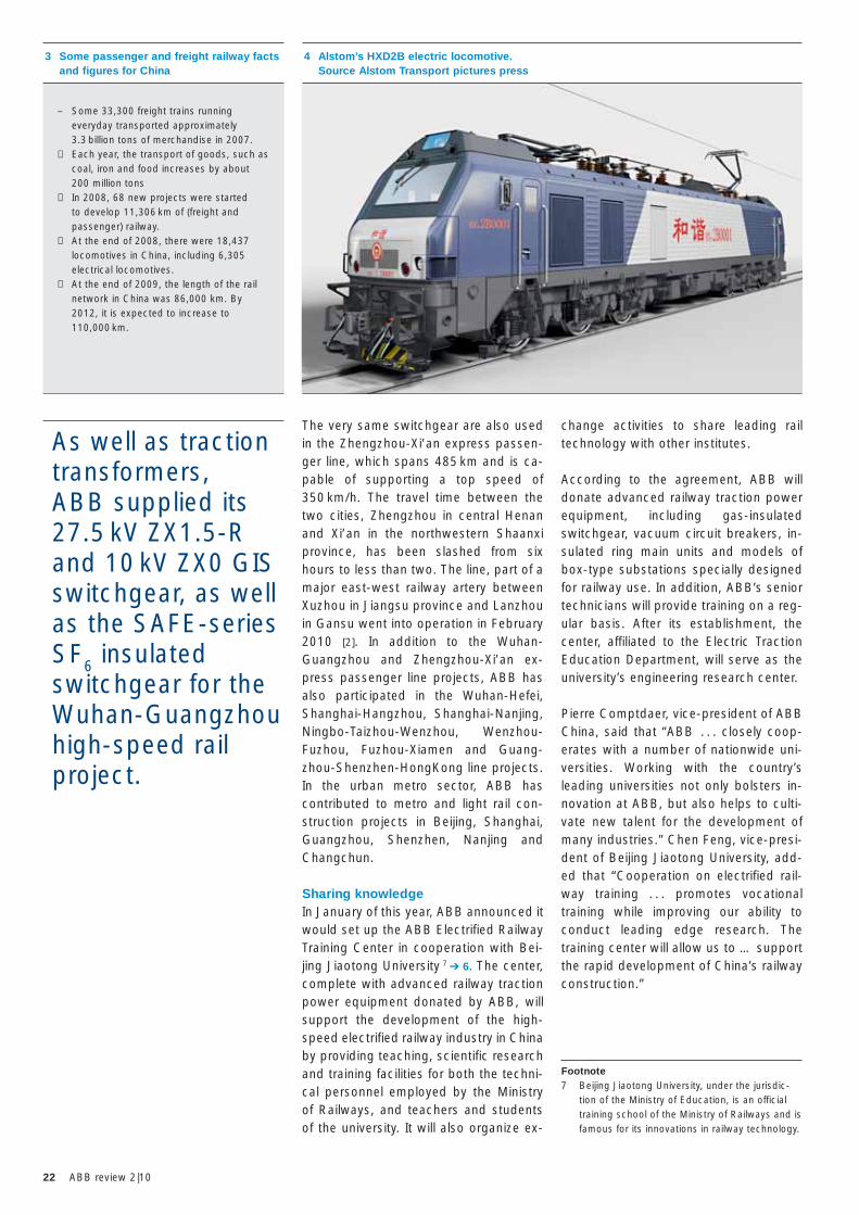
January 2007. Also in 2007, these two companies signed another contract worth 1.2 billion euros for the delivery of 500 HXD2B electric 6-axle locomotives. The HXD2B locomotive, also called CoCo in China, was designed by Alstom.
The traction transformers for both the HXD2 and HXD2B locomotives were supplied by ABB to Alstom, in a repeat of what have been past and successful ABB/Alstom collaborations ➔ 4. And fi-nally, ABB will also supply traction trans-formers for Alstom’s HXD2C electric loco motives in the near future.
Switching into gearTraction transformers are not the only power products supplied by ABB. For the Wuhan-Guangzhou high-speed rail project, ABB supplied a series of other products, including its 27.5 kV ZX1.5-R and 10 kV ZX0 GIS switchgear, as well as the SAFE-series SF6 insulated switch-gear that are used in the railway signal system power supply ➔ 5. The ZX1.5-R GIS switchgear are modular and flexible single busbar two-phase panels and were specially designed at ABB China’s medium-voltage technical center to ad-dress the highly specific railway power supply requirements of China’s electrified high-speed railways. Manufactured by ABB Xiamen Switchgear Co. Ltd., ZX1.5-R GIS switchgear use up to 70 percent less space than other conventional prod-ucts. Insulation is provided by SF6, which is well known for its remarkable physical characteristics, especially its excellent insulating capacity. With fewer mainte-nance requirements, customers are able to lower their total investment and oper-ating costs. Their deployment in substa-tions will help provide safe and reliable power along the entire rail line.
In 2009, ABB was contracted by Datong Electric Locomotive Co. Ltd. (DELC) to assemble traction transformers for the CRH2 (a modified E2-1000 series Shink-
ansen design from Japan) and to manufacture trac-tion transformers for the CRH5 EMU trains (manufac-tured by Alstom and Changchun Railway Vehicles). Also in 2009, ABB was contracted to upgrade the trac-tion transformer design for the Ka-
wasaki-derived CRH2-380, an EMU train capable of speeds of up to 380 km/h.
Growth in freight transportation
A growing economy requires better and faster rail freight transportation if such growth is to be sustained. To meet this demand, the Ministry of Railways has also been enhancing its railway freight transportation capacity by increasing and upgrading its entire freight network, with of course the support of ABB ➔ 3.
In 2005, Alstom and DELC signed a 350 million euro contract to manufacture a total of 180 electric 8-axle locomotives HXD2 6. This type of locomotive, used by the Daqin railway company Ltd., trans-ports coal to power plants and factories around China. The first HXD2, also known as BoBo, was completed in De-cember 2006 and arrived in TianJing in
can reach speeds of up to 250 km/h (155 mph) in regular service. In Septem-ber 2009, Bombardier Sifang Power won a further contract to supply the Chinese
Ministry of Railways with 80 Zefiro 380 very high-speed (VHS) trains 3 ➔ 1. A total of 1,120 rail cars will be built for China’s 6,000 km of new high-speed railways and ABB will supply the traction trans-formers for all these trains.
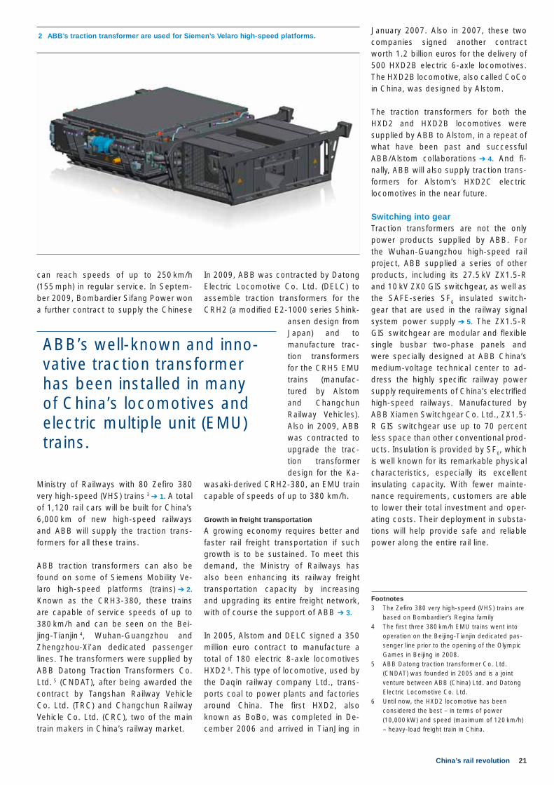
ABB traction transformers can also be found on some of Siemens Mobility Ve-laro high-speed platforms (trains) ➔ 2. Known as the CRH3-380, these trains are capable of service speeds of up to 380 km/h and can be seen on the Bei-jing-Tianjin 4, Wuhan-Guangzhou and Zhengzhou-Xi’an dedicated passenger lines. The transformers were supplied by ABB Datong Traction Transformers Co. Ltd. 5 (CNDAT), after being awarded the contract by Tangshan Railway Vehicle Co. Ltd. (TRC) and Changchun Railway Vehicle Co. Ltd. (CRC), two of the main train makers in China’s railway market.
2 ABB’s traction transformer are used for Siemen’s Velaro high-speed platforms.
ABB’s well-known and inno-vative traction transformer has been installed in many of China’s locomotives and electric multiple unit (EMU) trains.
Footnotes3 The Zefiro 380 very high-speed (VHS) trains are
based on Bombardier’s Regina family4 The first three 380 km/h EMU trains went into
operation on the Beijing-Tianjin dedicated pas-senger line prior to the opening of the Olympic Games in Beijing in 2008.
5 ABB Datong traction transformer Co. Ltd. (CNDAT) was founded in 2005 and is a joint venture between ABB (China) Ltd. and Datong Electric Locomotive Co. Ltd.
6 Until now, the HXD2 locomotive has been considered the best – in terms of power (10,000 kW) and speed (maximum of 120 km/h) – heavy-load freight train in China.
22 ABB review 2|10
change activities to share leading rail technology with other institutes.
According to the agreement, ABB will donate advanced railway traction power equipment, including gas-insulated switchgear, vacuum circuit breakers, in-sulated ring main units and models of box-type substations specially designed for railway use. In addition, ABB’s senior technicians will provide training on a reg-ular basis. After its establishment, the center, affiliated to the Electric Traction Education Department, will serve as the university’s engineering research center.
Pierre Comptdaer, vice-president of ABB China, said that “ABB . . . closely coop-erates with a number of nationwide uni-versities. Working with the country’s leading universities not only bolsters in-novation at ABB, but also helps to culti-vate new talent for the development of many industries.” Chen Feng, vice-presi-dent of Beijing Jiaotong University, add-ed that “Cooperation on electrified rail-way training . . . promotes vocational training while improving our ability to conduct leading edge research. The training center will allow us to … support the rapid development of China’s railway construction.”
The very same switchgear are also used in the Zhengzhou-Xi’an express passen-ger line, which spans 485 km and is ca-pable of supporting a top speed of 350 km/h. The travel time between the two cities, Zhengzhou in central Henan and Xi’an in the northwestern Shaanxi province, has been slashed from six hours to less than two. The line, part of a major east-west railway artery between Xuzhou in Jiangsu province and Lanzhou in Gansu went into operation in February 2010 [2]. In addition to the Wuhan-Guangzhou and Zhengzhou-Xi’an ex-press passenger line projects, ABB has also participated in the Wuhan-Hefei, Shanghai-Hangzhou, Shanghai-Nanjing, Ningbo-Taizhou-Wenzhou, Wenzhou-Fuzhou, Fuzhou-Xiamen and Guang-zhou-Shenzhen-HongKong line projects. In the urban metro sector, ABB has contributed to metro and light rail con-struction projects in Beijing, Shanghai, Guangzhou, Shenzhen, Nanjing and Changchun.
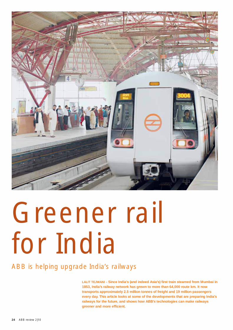
Sharing knowledgeIn January of this year, ABB announced it would set up the ABB Electrified Railway Training Center in cooperation with Bei-jing Jiaotong University 7 ➔ 6. The center, complete with advanced railway traction power equipment donated by ABB, will support the development of the high-speed electrified railway industry in China by providing teaching, scientific research and training facilities for both the techni-cal personnel employed by the Ministry of Railways, and teachers and students of the university. It will also organize ex-
4 Alstom’s HXD2B electric locomotive. Source Alstom Transport pictures press
3 Some passenger and freight railway facts and figures for China
– Some 33,300 freight trains running everyday transported approximately 3.3 billion tons of merchandise in 2007.
− Each year, the transport of goods, such as coal, iron and food increases by about 200 million tons
− In 2008, 68 new projects were started to develop 11,306 km of (freight and passenger) railway.
− At the end of 2008, there were 18,437 locomotives in China, including 6,305 electrical locomotives.
− At the end of 2009, the length of the rail network in China was 86,000 km. By 2012, it is expected to increase to 110,000 km.
Footnote7 Beijing Jiaotong University, under the jurisdic-
tion of the Ministry of Education, is an official training school of the Ministry of Railways and is famous for its innovations in railway technology.
As well as traction transformers, ABB supplied its 27.5 kV ZX1.5-R and 10 kV ZX0 GIS switchgear, as well as the SAFE-series SF6 insulated switchgear for the Wuhan-Guangzhou high-speed rail project.
23China’s rail revolution
Cécile Félon
Frédéric Ramella
Harry Züger
ABB Power Products
Geneva, Switzerland
References[1] High-speed rail in China. (nd) Retrieved March
2, 2010 from http://en.wikipedia.org/wiki/High-speed_rail_in_China.
[2] China daily (2010, February 6). Zhengzhou-Xi’an high-speed train starts operation. Retrieved March 2, 2010 from http://www.chinadaily.com.cn/regional/2010-02/06/content_9439243.htm.
[3] The Economist (2010, February 4). China’s dashing new trains. Retrieved March 2, 2009 from http://www.economist.com/blogs/gulliver/2010/02/high-speed_rail_china.
people. In fact, high-speed rail is likely to be just as fast as air travel at half the price! According to Si Xianmin, chairman of China Southern Airlines, the largest domestic airline by fleet size, “High-speed rail has three advantages over air travel: it is more convenient, more punc-tual and has a better safety record. This could help erode the airlines’ market shares.”[3] In addition, a good rail net-work may help spread economic devel-opment more quickly and evenly around the country.
The success of ABB in the Chinese Rail-way market is based on the close coop-eration between ABB Sécheron and ABB
Datong ➔ 7. While ABB Sécheron is the global leader in design, research and development, marketing and sales as well as service of power products for the rail sector, ABB Datong focuses on the production of traction transform-ers for the Chinese market. ABB is
currently positioning itself in the Chinese EMU market to become the supplier of choice of power products and systems for China’s increasing number of com-muter trains.
This is not the first collaboration between ABB and a Chinese university. In fact, ABB has consistently supported educa-tion in China to ensure the availability of highly skilled technicians. For example, in 2008 the company set up the ABB Power Technology Education Center in Tongji University and supplied it with a complete set of transformer substation and feeder automation products as well as primary products, such as medium-voltage switchgear, a ring main unit (RMU) and outdoor products, to encour-age more advanced teaching and re-search. In addition, ABB also cooperates with Tsing-Hua University, North China Electric Power University, Tianjin Univer-
sity, Shanghai Jiaotong University and Chongqing University on various re-search projects.
Being connectedBy improving connections, China’s high-speed rail network will no doubt make travel available to ever larger numbers of
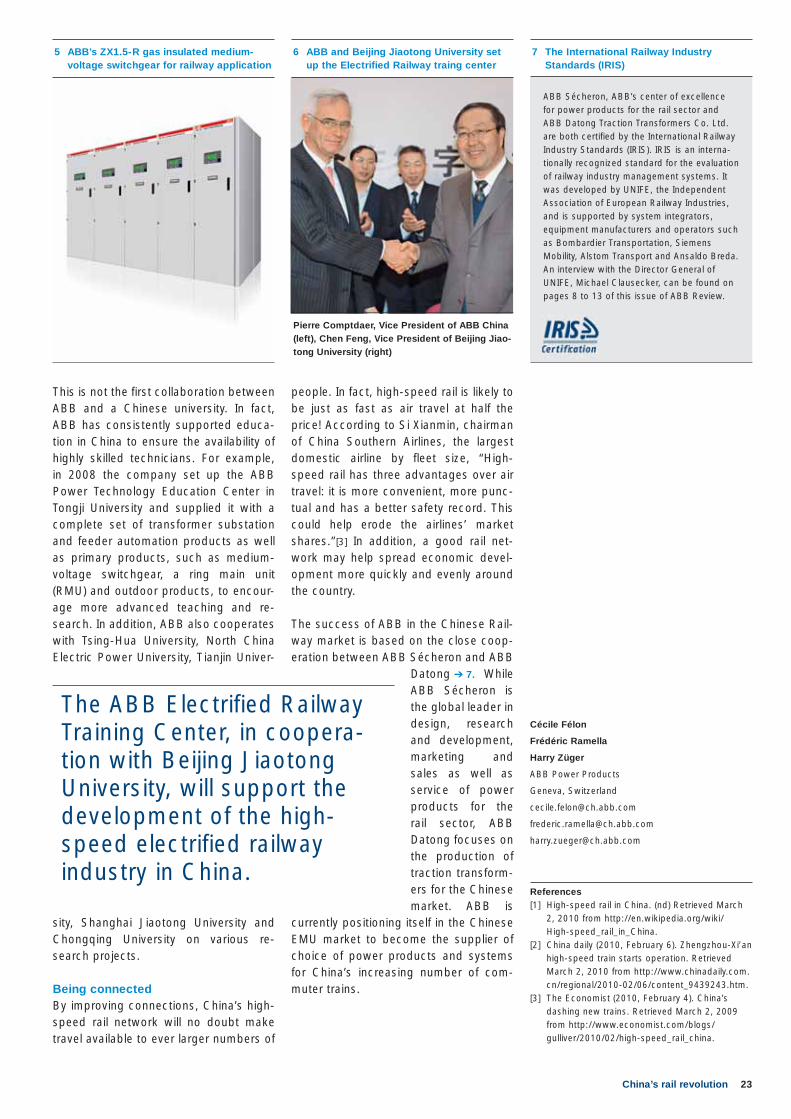
5 ABB’s ZX1.5-R gas insulated medium-voltage switchgear for railway application
6 ABB and Beijing Jiaotong University set up the Electrified Railway traing center
The ABB Electrified Railway Training Center, in coopera-tion with Beijing Jiaotong University, will support the development of the high-speed electrified railway industry in China.
7 The International Railway Industry Standards (IRIS)
ABB Sécheron, ABB’s center of excellence for power products for the rail sector and ABB Datong Traction Transformers Co. Ltd. are both certified by the International Railway Industry Standards (IRIS). IRIS is an interna -tionally recognized standard for the evaluation of railway industry management systems. It was developed by UNIFE, the Independent Association of European Railway Industries, and is supported by system integrators, equipment manufacturers and operators such as Bombardier Transportation, Siemens Mobility, Alstom Transport and Ansaldo Breda. An interview with the Director General of UNIFE, Michael Clausecker, can be found on pages 8 to 13 of this issue of ABB Review.
Pierre Comptdaer, Vice President of ABB China (left), Chen Feng, Vice President of Beijing Jiao-tong University (right)
24 ABB review 2|10
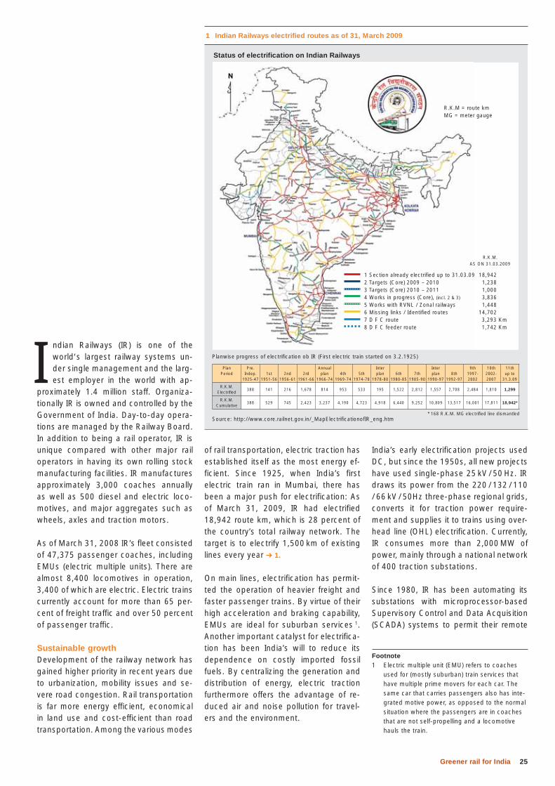
LALIT TEJWANI – Since India’s (and indeed Asia’s) fi rst train steamed from Mumbai in 1853, India’s railway network has grown to more than 64,000 route km. It now transports approximately 2.5 million tonnes of freight and 19 million passengers every day. This article looks at some of the developments that are preparing India’s railways for the future, and shows how ABB’s technologies can make railways greener and more effi cient.
ABB is helping upgrade India’s railways
Greener rail for India
25Greener rail for India
India’s early electrification projects used DC, but since the 1950s, all new projects have used single-phase 25 kV / 50 Hz. IR draws its power from the 220 / 132 / 110 / 66 kV / 50Hz three-phase regional grids, converts it for traction power require-ment and supplies it to trains using over-head line (OHL) electrification. Currently, IR consumes more than 2,000 MW of power, mainly through a national network of 400 traction substations.
Since 1980, IR has been automating its substations with microprocessor-based Supervisory Control and Data Acquisition (SCADA) systems to permit their remote
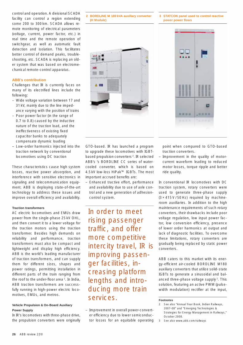
of rail transportation, electric traction has established itself as the most energy ef-ficient. Since 1925, when India’s first electric train ran in Mumbai, there has been a major push for electrification: As of March 31, 2009, IR had electrified 18,942 route km, which is 28 percent of the country’s total railway network. The target is to electrify 1,500 km of existing lines every year ➔ 1.
On main lines, electrification has permit-ted the operation of heavier freight and faster passenger trains. By virtue of their high acceleration and braking capability, EMUs are ideal for suburban services 1. Another important catalyst for electrifica-tion has been India’s will to reduce its dependence on costly imported fossil fuels. By centralizing the generation and distribution of energy, electric traction furthermore offers the advantage of re-duced air and noise pollution for travel-ers and the environment.
I ndian Railways (IR) is one of the world‘s largest railway systems un-der single management and the larg-est employer in the world with ap-
proximately 1.4 million staff. Organiza -tionally IR is owned and controlled by the Government of India. Day-to-day opera-tions are managed by the Railway Board. In addition to being a rail operator, IR is unique compared with other major rail operators in having its own rolling stock manufacturing facilities. IR manufactures approximately 3,000 coaches annually as well as 500 diesel and electric loco-motives, and major aggregates such as wheels, axles and traction motors.
As of March 31, 2008 IR’s fleet consisted of 47,375 passenger coaches, including EMUs (electric multiple units). There are almost 8,400 locomotives in operation, 3,400 of which are electric. Electric trains currently account for more than 65 per-cent of freight traffic and over 50 percent of passenger traffic.
Sustainable growthDevelopment of the railway network has gained higher priority in recent years due to urbanization, mobility issues and se-vere road congestion. Rail transportation is far more energy efficient, economical in land use and cost-efficient than road transportation. Among the various modes
Footnote1 Electric multiple unit (EMU) refers to coaches
used for (mostly suburban) train services that have multiple prime movers for each car. The same car that carries passengers also has inte-grated motive power, as opposed to the normal situation where the passengers are in coaches that are not self-propelling and a locomotive hauls the train.
1 Indian Railways electrified routes as of 31, March 2009
Source: http://www.core.railnet.gov.in/_MapElectrificationofIR_eng.htm* 168 R.K.M. MG electrified line dismantled
Planwise progress of electrification ob IR (First electric train started on 3.2.1925)
Status of electrification on Indian Railways
1 Section already electrified up to 31.03.09 18,9422 Targets (Core) 2009 – 2010 1,2383 Targets (Core) 2010 – 2011 1,0004 Works in progress (Core), (incl. 2 & 3) 3,8365 Works with RVNL / Zonal railways 1,4486 Missing links / Identified routes 14,7027 D F C route 3,293 Km8 D F C feeder route 1,742 Km
R.K.M.AS ON 31.03.2009
PlanPeriod
Pre.Indep.
1925-471st
1951-562nd
1956-612rd
1961-66
Annualplan
1966-744th
1969-745th
1974-78
Interplan
1978-806th
1980-857th
1985-90
Interplan
1990-978th
1992-97
9th1997-2002
10th2002-2007
11thup to
31.3.09
R.K.M.Electrified
388 141 216 1,678 814 953 533 195 1,522 2,812 1,557 2,708 2,484 1,810 1,299
R.K.M.Cumulative
388 529 745 2,423 3,237 4,190 4,723 4,918 6,440 9,252 10,809 13,517 16,001 17,811 18,942*
R.K.M = route kmMG = meter gauge
26 ABB review 2|10
GTO-based. IR has launched a program to upgrade these locomotives with IGBT-based propulsion converters 3. IR selected ABB’s ’s BORDLINE CC series of water-cooled converter, which is based on 4.5 kV low-loss HiPak™ IGBTs. The most important accrued benefi ts are:– Enhanced tractive effort, performance
and availability due to use of axle con-trol and a new generation of adhesion-control system.
– Improvement in overall power-convert-er efficiency due to lower semiconduc-tor losses for an equitable operating
control and operation. A divisional SCADA facility can control a region extending some 200 to 300 km. SCADA allows re-mote monitoring of electrical parameters (voltage, current, power factor, etc.) in real time and the remote operation of switchgear, as well as automatic fault detection and isolation. This facilitates better control of demand peaks, trouble-shooting, etc. SCADA is replacing an old-er system that was based on electrome-chanical remote-control apparatus.
ABB’s contributionChallenges that IR is currently faces on many of its electrified lines include the following:– Wide voltage variation between 17 and
31 kV, mainly due to the line imped-ance varying with the position of trains
– Poor power factor (in the range of 0.7 to 0.8) caused by the inductive nature of the traction load, and the ineffectiveness of existing fixed capacitor banks to adequately compensate dynamic loading
– Low-order harmonics injected into the traction network by conventional locomotives using DC traction
These characteristics cause high system losses, reactive power absorption, and interference with sensitive electronics in signaling and telecommunication equip-ment. ABB is deploying state-of-the-art technology to address these issues and improve overall efficiency and availability.
Traction transformers
AC electric locomotives and EMUs draw power from the single-phase 25 kV OHL, and then convert it to a lower voltage for the traction motors using the traction transformer. Besides high demands on reliability and performance, traction transformers must also be compact and lightweight and display high efficiency. ABB is the world’s leading manufacturer of traction transformers, and can supply them for different sizes, shapes and power ratings, permitting installation in different parts of the train ranging from the roof to the under-floor area 2. In India, ABB traction transformers are success-fully running in high-power electric loco-motives, EMUs, and metros.
Vehicle Propulsion & On-Board Auxiliary
Power Supply
In IR’s locomotives with three-phase drive, the propulsion converters were originally
3 STATCON panel used to control reactive power power flows
2 BORDLINE M 180 kVA auxiliary converter (H Module)
In order to meet rising passenger traffic, and offer more competitive intercity travel, IR is improving passen-ger facilities, in-creasing platform lengths and intro-ducing more train services. Footnotes
2 See also “Annual Year Book, Indian Railways, 2007-08” and “Emerging Technologies & Strategies for Energy Management in Railways,” October 2008.
3 See also www.abb.com/railways
point when compared to GTO-based traction converters.
– Improvement in the quality of motor-current waveform leading to reduced motor losses, torque ripple and better ride quality.
In conventional IR locomotives with DC traction system, rotary converters were used to generate three-phase supply (3 × 415 V / 50 Hz) required by machine-room auxiliaries. In addition to the high maintenance requirements of such rotary converters, their drawbacks include poor voltage regulation, low input power fac-tor, low conversion efficiency, presence of lower order harmonics at output and lack of diagnostic facilities. To overcome these limitations, rotary converters are gradually being replaced by static power converters.
ABB caters to this market with its ener-gy-efficient air-cooled BORDLINE M180 auxiliary converters that utilize solid-state IGBTs to generate a sinusoidal and bal-anced three-phase voltage supply 2. This solution, featuring an active PWM (pulse-width modulation) rectifier at the input,
27Greener rail for India
only penalize IR when the power factor is lagging, but in some cases also when the power factor is leading as a result of over-compensation. Sub-stations thus need reactive power compensation that can be adjusted dynamically and in real time.
ABB’s STATCON is a voltage source converter / inverter that can both absorb and deliver reactive power ➔ 3. It uses IGBT switching devices and is modular, permitting future expansion should de-mand rise.
STATCON is shunt-connected and there-fore easy to install. It totally relieves the source from reactive power, resulting in better utilization of the supply equipment and network. Also by providing very fast dynamic compensation, it improves volt-age profile and reduces system losses and hence the loading on incoming pow-er transformers, switchgear, cables, etc.
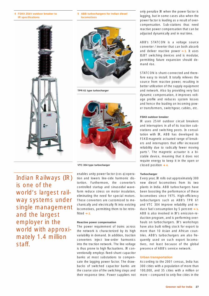
FSKII outdoor breaker
IR uses 25 kV outdoor circuit breakers and interrupters in all of its traction sub-stations and switching posts. In consul-tation with IR, ABB has developed its FSKII magnetic actuated range of break-ers and interrupters that offer increased reliability due to radically fewer moving parts 2. The magnetic actuator is a bi-stable device, meaning that it does not require energy to keep it in the open or closed position ➔ 4.
Turbocharger
Every year, IR rolls out approximately 300 new diesel locomotives from its two plants in India. ABB turbochargers have been boosting the performance of these locomotives since 1975. High-efficiency turbochargers such as ABB’s TPR 61 and VTC 304 improve reliability and re-duce fuel consumption by 5 percent ➔ 5. ABB is also involved in IR’s emission-re-duction program, and is performing over-hauls on turbochargers. IR’s workshops have also built rolling stock for export to more than 10 Asian and African coun-tries. ABB’s turbochargers are also fre-quently used on such export locomo-tives, not least because of the global presence of ABB’s service network.
Urban transportation According to the 2001 census, India has 300 cities with a population of more than 100,000, and 35 cities with a million or more – compared to only five cities in the
enables unity power factor (cos φ) opera-tion and lowers line-side harmonic dis-tortion. Furthermore, the converter’s controlled startup and sinusoidal wave-form reduce stress on motor insulation, eliminating the need for special motors. These converters are customized to me-chanically and electrically fit into existing locomotives, permitting them to be retro-fitted ➔ 2.
Reactive power compensation
The power requirement of trains across the network is characterized by its high variability in demand. In addition, traction converters inject low-order harmonics into the traction network. The line voltage is thus prone to high fl uctuations. IR con-ventionally employs fi xed-shunt capacitor banks at most substations to compen-sate the lagging power factor. The draw-backs of switched capacitor banks are the coarse size of the switching steps and their response time. Power suppliers not
5 ABB turbochargers for Indian diesel locomotives
TPR 61 type turbocharger
VTC 304 type turbocharger
4 FSKII 25kV outdoor breaker to IR specifications
Indian Railways (IR) is one of the world‘s largest rail-way systems under single management and the largest employer in the world with approxi-mately 1.4 million staff.
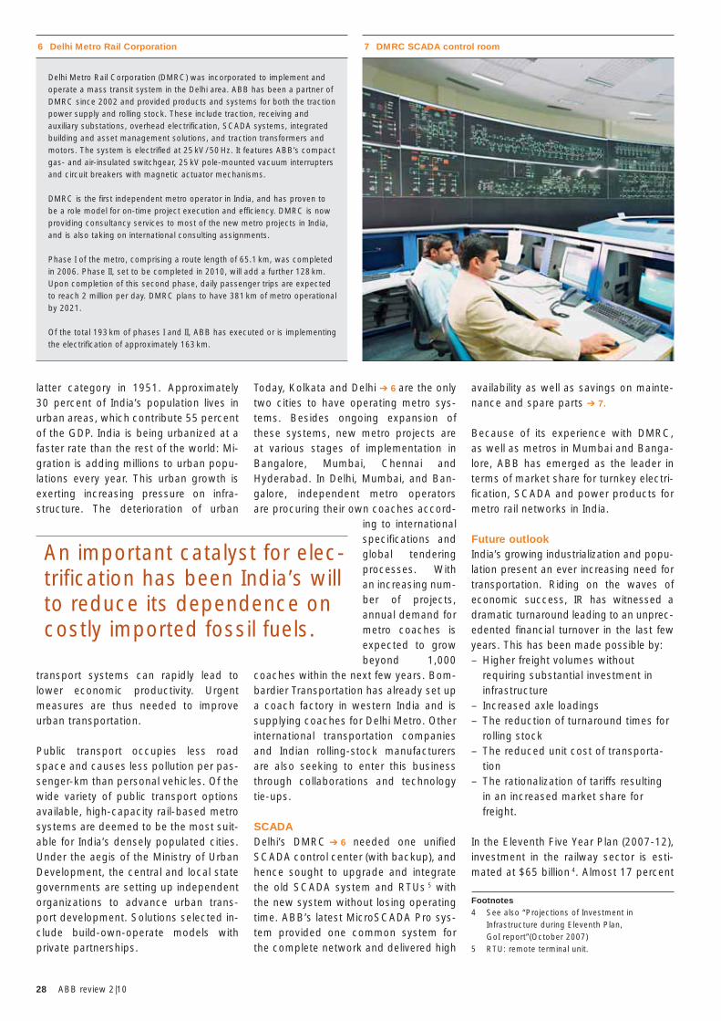
28 ABB review 2|10
availability as well as savings on mainte-nance and spare parts ➔ 7.
Because of its experience with DMRC, as well as metros in Mumbai and Banga-lore, ABB has emerged as the leader in terms of market share for turnkey electri-fication, SCADA and power products for metro rail networks in India.
Future outlookIndia’s growing industrialization and popu-lation present an ever increasing need for transportation. Riding on the waves of economic success, IR has witnessed a dramatic turnaround leading to an unprec-edented fi nancial turnover in the last few years. This has been made possible by: – Higher freight volumes without
requiring substantial investment in infrastructure
– Increased axle loadings– The reduction of turnaround times for
rolling stock – The reduced unit cost of transporta-
tion– The rationalization of tariffs resulting
in an increased market share for freight.
In the Eleventh Five Year Plan (2007-12), investment in the railway sector is esti-mated at $65 billion 4. Almost 17 percent
Today, Kolkata and Delhi ➔ 6 are the only two cities to have operating metro sys-tems. Besides ongoing expansion of these systems, new metro projects are at various stages of implementation in Bangalore, Mumbai, Chennai and Hyderabad. In Delhi, Mumbai, and Ban-galore, independent metro operators are procuring their own coaches accord-
ing to international specifications and global tendering processes. With an increasing num-ber of projects, annual demand for metro coaches is expected to grow beyond 1,000
coaches within the next few years. Bom-bardier Transportation has already set up a coach factory in western India and is supplying coaches for Delhi Metro. Other international transportation companies and Indian rolling-stock manufacturers are also seeking to enter this business through collaborations and technology tie-ups.
SCADADelhi’s DMRC ➔ 6 needed one unified SCADA control center (with backup), and hence sought to upgrade and integrate the old SCADA system and RTUs 5 with the new system without losing operating time. ABB’s latest MicroSCADA Pro sys-tem provided one common system for the complete network and delivered high
latter category in 1951. Approximately 30 percent of India’s population lives in urban areas, which contribute 55 percent of the GDP. India is being urbanized at a faster rate than the rest of the world: Mi-gration is adding millions to urban popu-lations every year. This urban growth is exerting increasing pressure on infra-structure. The deterioration of urban
transport systems can rapidly lead to lower economic productivity. Urgent measures are thus needed to improve urban transportation.
Public transport occupies less road space and causes less pollution per pas-senger-km than personal vehicles. Of the wide variety of public transport options available, high-capacity rail-based metro systems are deemed to be the most suit-able for India’s densely populated cities. Under the aegis of the Ministry of Urban Development, the central and local state governments are setting up independent organizations to advance urban trans-port development. Solutions selected in-clude build-own-operate models with private partnerships.
7 DMRC SCADA control room 6 Delhi Metro Rail Corporation
Delhi Metro Rail Corporation (DMRC) was incorporated to implement and operate a mass transit system in the Delhi area. ABB has been a partner of DMRC since 2002 and provided products and systems for both the traction power supply and rolling stock. These include traction, receiving and auxiliary substations, overhead electrifi cation, SCADA systems, inte gra ted building and asset management solutions, and traction transformers and motors. The system is electrifi ed at 25 kV / 50 Hz. It features ABB’s compact gas- and air-insulated switchgear, 25 kV pole-mounted vacuum interrupters and circuit breakers with magnetic actuator mechanisms.
DMRC is the fi rst independent metro operator in India, and has proven to be a role model for on-time project execution and effi ciency. DMRC is now providing consultancy services to most of the new metro projects in India, and is also taking on international consulting assignments.
Phase I of the metro, comprising a route length of 65.1 km, was completed in 2006. Phase II, set to be completed in 2010, will add a further 128 km. Upon completion of this second phase, daily passenger trips are expected to reach 2 million per day. DMRC plans to have 381 km of metro operational by 2021.
Of the total 193 km of phases I and II, ABB has executed or is implementing the electrifi cation of approximately 163 km.
Footnotes4 See also “Projections of Investment in
Infrastructure during Eleventh Plan, GoI report”(October 2007)
5 RTU: remote terminal unit.
An important catalyst for elec-trification has been India’s will to reduce its dependence on costly imported fossil fuels.
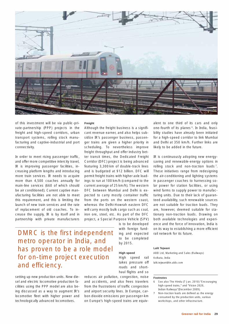
29Greener rail for India
alent to one third of its cars and only one-fourth of its planes 6. In India, feasi-bility studies have already been initiated for a high-speed corridor to link Mumbai and Delhi at 350 km/h. Further links are likely to be added in the future.
IR is continuously adopting new energy-saving and renewable-energy options in rolling stock and non-traction loads 7. These initiatives range from redesigning the air-conditioning and lighting systems in passenger coaches to harnessing so-lar power for station facilities, or using wind farms to supply power to manufac-turing units. Due to their lack of guaran-teed availability, such renewable sources are not suitable for traction loads. They are, however, deemed suitable for sta-tionary non-traction loads. Drawing on both available technologies and experi-ence and the force of innovation, India is on its way to establishing a more efficient rail network for its future.
Lalit Tejwani
ABB Ltd, Marketing and Sales (Railways)
Kolkata, India
Footnotes6 See also The Hindu (7 Jan. 2010) “Encouraging
high-speed trains,” and “Vision 2020, Indian Railways”(December 2009).
7 Non-traction loads are defined as the energy consumed by the production units, various workshops, and other infrastructure.
Freight
Although the freight business is a signifi-cant revenue earner, and also helps sub-sidize IR’s passenger business, passen-ger trains are given a higher priority in scheduling. To nevertheless improve freight throughput and offer industry bet-ter transit times, the Dedicated Freight Corridor (DFC) project is being advanced featuring 3,300 km of double-track lines and is budgeted at $12 billion. DFC will permit freight trains with higher axle load-ings to run at 100 km/h (compared to the current average of 25 km/h). The western DFC between Mumbai and Delhi is ex-pected to carry mostly container traffic from the ports on the western coast, whereas the Delhi-Howrah eastern DFC will carry mostly bulk cargo such as coal, iron ore, steel, etc. As part of the DFC project, a Special Purpose Vehicle (SPV)
is to be developed with foreign fund-ing and expected to be completed by 2015.
High speed
High speed rail takes pressure off roads and short-haul flights and so
reduces air pollution, congestion, noise and accidents, and also frees travelers from the frustrations of traffic congestion and airport security lines. In Europe, car-bon dioxide emissions per passenger-km on Europe’s high-speed trains are equiv-
of this investment will be via public-pri-vate-partnership (PPP) projects in the freight and high-speed corridors, urban transport systems, rolling stock manu-facturing and captive-industrial and port connectivity.
In order to meet rising passenger traffi c, and offer more competitive intercity travel, IR is improving passenger facilities, in-creasing platform lengths and introducing more train services. IR needs to acquire more than 4,500 coaches annually for main-line services (660 of which should be air conditioned). Current captive man-ufacturing facilities are not able to meet this requirement, and this is limiting the launch of new train services and the rate of replacement of old coaches. To in-crease the supply, IR is by itself and in partnership with private manufacturers
setting up new production units. New die-sel and electric locomotive production fa-cilities using the PPP model are also be-ing discussed as a way to augment IR’s locomotive fl eet with higher power and technologically advanced locomotives.
DMRC is the first independent metro operator in India, and has proven to be a role model for on-time project execution and efficiency.
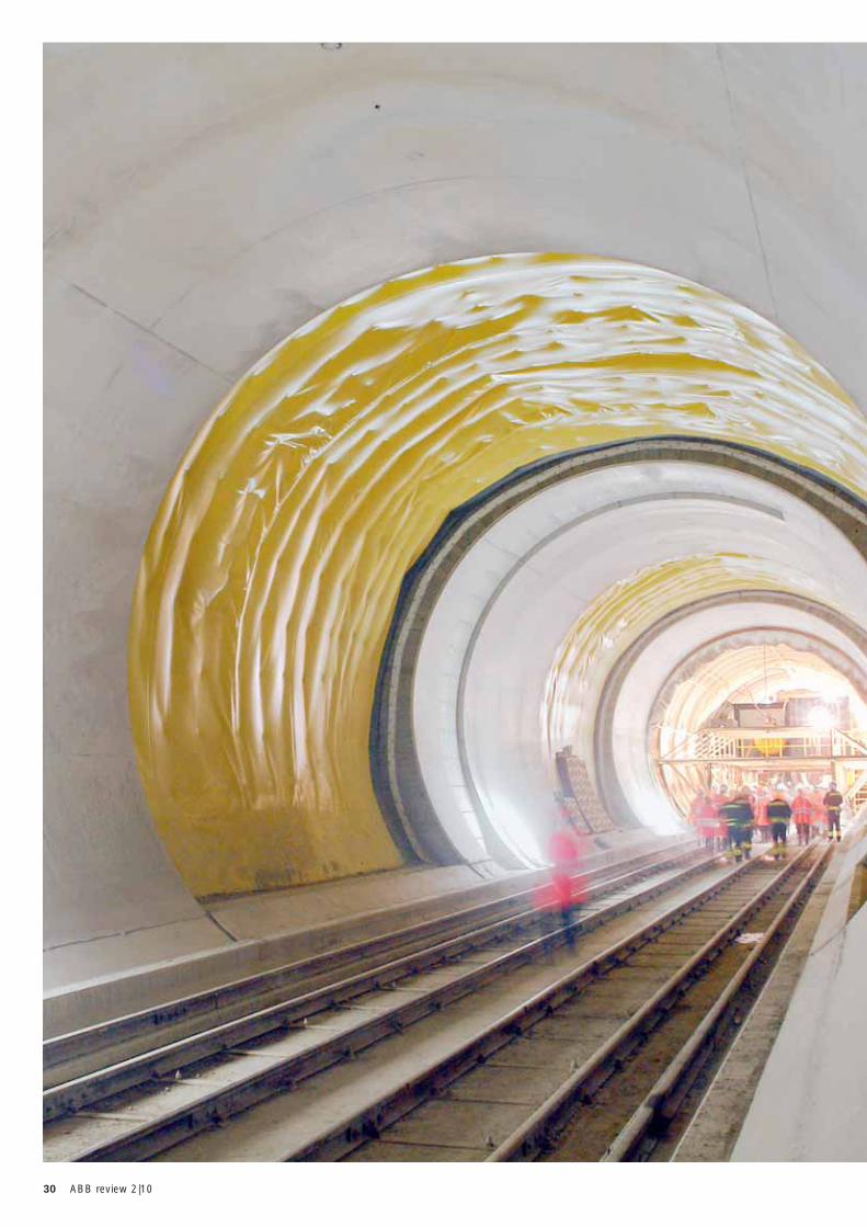
30 ABB review 2|10
31Switzerland by rail
has not only increased the frequency of its timetable, it also continually upgrades its rolling stock.
When it comes to rail transport in an in-ternational context, the Alpine country also sets milestones and pursues an ac-tive policy of transporting goods by train rather than truck, where possible. Today Switzerland is the most important transit country for goods crossing the Alps by rail. In 2008, 40 million tons of freight were transported through Switzerland, more than half of which – around 25 mil-lion metric tons – were transported by train [3]. Many referenda have also dem-onstrated the Swiss’ support for trans-port of goods by rail. An important step in enabling such rail transport is the con-struction of the New Railway Link through the Alps (NRLA), which integrates Swit-
Supplying traction power for the country’s major railway initiatives
RENÉ JENNI, REMIGIUS STOFFEL, MELANIE NYFELER – Switzerland is generally considered a pioneer when it comes to public transport. In no other part of the world are trains, trams and buses used as often as they are in this small Alpine country. In fact, so beloved is the public transportation system in Switzerland that its people have repeatedly voted in favor of extending the already comprehensive rail network even further. The country’s aim is to carry more travelers on public transport and transfer more freight from road to rail. ABB is participating in this effort, supplying the power for the two new base tunnels through the Alps – the Lötschberg and the Gotthard – as well as DC traction substations for public transport in the conurbations around the cities of Zurich, Bern and Luzern.
Switzerland by rail
S tudies repeatedly show that the Swiss are world champi-ons when it comes to travel-ing by train. On average, each
of the country’s residents travels 40 times each year on Swiss trains, amounting to about 900,000 people on the Swiss rail-road system every single day [1,2] ➔ 1. Not surprisingly Switzerland has the highest frequency of train services in the world.
Thanks to the strategic transportation policy of the Swiss government, Switzer-land has a very well developed rail net-work, which ensures that rural areas can be reached and offers rail connections between cities that operate every hour or even every half hour. To meet the grow-ing demand, Swiss Federal Railways (Schweizerische Bundesbahnen, or SBB) Photo © AlpTransit Gotthard Ltd.
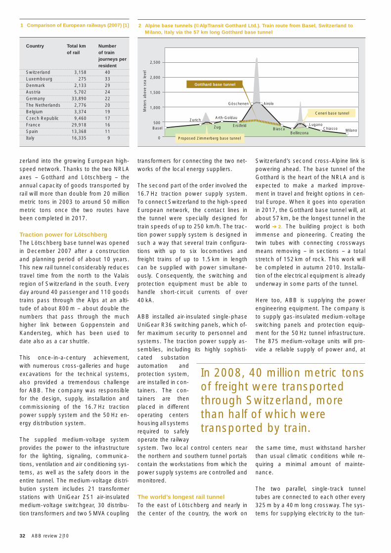
32 ABB review 2|10
Switzerland’s second cross-Alpine link is powering ahead. The base tunnel of the Gotthard is the heart of the NRLA and is expected to make a marked improve-ment in travel and freight options in cen-tral Europe. When it goes into operation in 2017, the Gotthard base tunnel will, at about 57 km, be the longest tunnel in the world ➔ 2. The building project is both immense and pioneering. Creating the twin tubes with connecting crossways means removing – in sections – a total stretch of 152 km of rock. This work will be completed in autumn 2010. Installa-tion of the electrical equipment is already underway in some parts of the tunnel.
Here too, ABB is supplying the power engineering equipment. The company is to supply gas-insulated medium-voltage switching panels and protection equip-ment for the 50 Hz tunnel infrastructure. The 875 medium-voltage units will pro-vide a reliable supply of power and, at
the same time, must withstand harsher than usual climatic conditions while re-quiring a minimal amount of mainte-nance.
The two parallel, single-track tunnel tubes are connected to each other every 325 m by a 40 m long crossway. The sys-tems for supplying electricity to the tun-
transformers for connecting the two net-works of the local energy suppliers.
The second part of the order involved the 16.7 Hz traction power supply system. To connect Switzerland to the high-speed European network, the contact lines in the tunnel were specially designed for train speeds of up to 250 km/h. The trac-tion power supply system is designed in such a way that several train configura-tions with up to six locomotives and freight trains of up to 1.5 km in length can be supplied with power simultane-ously. Consequently, the switching and protection equipment must be able to handle short-circuit currents of over 40 kA.
ABB installed air-insulated single-phase UniGear R36 switching panels, which of-fer maximum security to personnel and systems. The traction power supply as-semblies, including its highly sophisti-cated substation automation and protection system, are installed in con-tainers. The con-tainers are then placed in different operating centers housing all systems required to safely operate the railway system. Two local control centers near the northern and southern tunnel portals contain the workstations from which the power supply systems are controlled and monitored.
The world’s longest rail tunnel To the east of Lötschberg and nearly in the center of the country, the work on
1 Comparison of European railways (2007) [1]
Country Total km Number of rail of train journeys per resident
Switzerland 3,158 40Luxembourg 275 33Denmark 2,133 29Austria 5,702 24Germany 33,890 22The Netherlands 2,776 20Belgium 3,374 19Czech Republic 9,460 17France 29,918 16Spain 13,368 11Italy 16,335 9
2,500
2,000
1,500
1,000
500
0
Zurich
Göschenen
Met
ers
abov
e se
a le
vel
Gotthard base tunnel
Proposed Zimmerberg base tunnel
Ceneri base tunnel
Airolo
Arth-Goldau
Zug ErstfeldBiasca
Bellinzona
LuganoChiasso MilanoBasel
2 Alpine base tunnels (©AlpTransit Gotthard Ltd.). Train route from Basel, Switzerland to Milano, Italy via the 57 km long Gotthard base tunnel
In 2008, 40 million metric tons of freight were transported through Switzerland, more than half of which were transported by train.
zerland into the growing European high-speed network. Thanks to the two NRLA axes – Gotthard and Lötschberg – the annual capacity of goods transported by rail will more than double from 20 million metric tons in 2003 to around 50 million metric tons once the two routes have been completed in 2017.
Traction power for LötschbergThe Lötschberg base tunnel was opened in December 2007 after a construction and planning period of about 10 years. This new rail tunnel considerably reduces travel time from the north to the Valais region of Switzerland in the south. Every day around 40 passenger and 110 goods trains pass through the Alps at an alti-tude of about 800 m – about double the numbers that pass through the much higher link between Goppenstein and Kandersteg, which has been used to date also as a car shuttle.
This once-in-a-century achievement, with numerous cross-galleries and huge excavations for the technical systems, also provided a tremendous challenge for ABB. The company was responsible for the design, supply, installation and commissioning of the 16.7 Hz traction power supply system and the 50 Hz en-ergy distribution system.
The supplied medium-voltage system provides the power to the infrastructure for the lighting, signaling, communica-tions, ventilation and air conditioning sys-tems, as well as the safety doors in the entire tunnel. The medium-voltage distri-bution system includes 21 transformer stations with UniGear ZS1 air-insulated medium-voltage switchgear, 30 distribu-tion transformers and two 5 MVA coupling
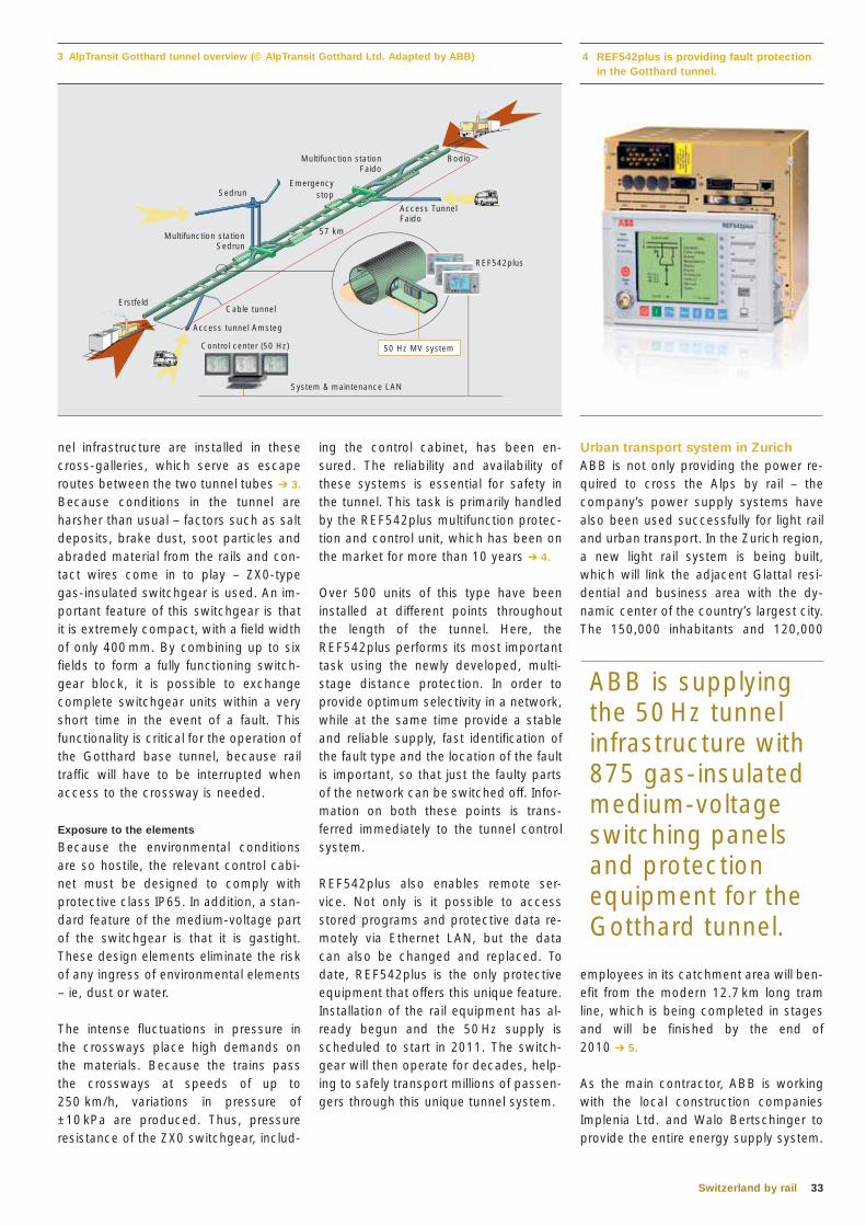
33Switzerland by rail
ing the control cabinet, has been en-sured. The reliability and availability of these systems is essential for safety in the tunnel. This task is primarily handled by the REF542plus multifunction protec-tion and control unit, which has been on the market for more than 10 years ➔ 4.
Over 500 units of this type have been installed at different points throughout the length of the tunnel. Here, the REF542plus performs its most important task using the newly developed, multi-stage distance protection. In order to provide optimum selectivity in a network, while at the same time provide a stable and reliable supply, fast identification of the fault type and the location of the fault is important, so that just the faulty parts of the network can be switched off. Infor-mation on both these points is trans-ferred immediately to the tunnel control system.
REF542plus also enables remote ser-vice. Not only is it possible to access stored programs and protective data re-motely via Ethernet LAN, but the data can also be changed and replaced. To date, REF542plus is the only protective equipment that offers this unique feature. Installation of the rail equipment has al-ready begun and the 50 Hz supply is scheduled to start in 2011. The switch-gear will then operate for decades, help-ing to safely transport millions of passen-gers through this unique tunnel system.
nel infrastructure are installed in these cross-galleries, which serve as escape routes between the two tunnel tubes ➔ 3. Because conditions in the tunnel are harsher than usual – factors such as salt deposits, brake dust, soot particles and abraded material from the rails and con-tact wires come in to play – ZX0-type gas-insulated switchgear is used. An im-portant feature of this switchgear is that it is extremely compact, with a field width of only 400 mm. By combining up to six fields to form a fully functioning switch-gear block, it is possible to exchange complete switchgear units within a very short time in the event of a fault. This functionality is critical for the operation of the Gotthard base tunnel, because rail traffic will have to be interrupted when access to the crossway is needed.
Exposure to the elements
Because the environmental conditions are so hostile, the relevant control cabi-net must be designed to comply with protective class IP65. In addition, a stan-dard feature of the medium-voltage part of the switchgear is that it is gastight. These design elements eliminate the risk of any ingress of environmental elements – ie, dust or water.
The intense fluctuations in pressure in the crossways place high demands on the materials. Because the trains pass the crossways at speeds of up to 250 km/h, variations in pressure of ±10 kPa are produced. Thus, pressure resistance of the ZX0 switchgear, includ-
Urban transport system in Zurich ABB is not only providing the power re-quired to cross the Alps by rail – the company’s power supply systems have also been used successfully for light rail and urban transport. In the Zurich region, a new light rail system is being built, which will link the adjacent Glattal resi-dential and business area with the dy-namic center of the country’s largest city. The 150,000 inhabitants and 120,000
employees in its catchment area will ben-efit from the modern 12.7 km long tram line, which is being completed in stages and will be finished by the end of 2010 ➔ 5.
As the main contractor, ABB is working with the local construction companies Implenia Ltd. and Walo Bertschinger to provide the entire energy supply system.
ABB is supplying the 50 Hz tunnel infrastructure with 875 gas-insulated medium-voltage switching panels and protection equipment for the Gotthard tunnel.
4 REF542plus is providing fault protection in the Gotthard tunnel.
3 AlpTransit Gotthard tunnel overview (© AlpTransit Gotthard Ltd. Adapted by ABB)
Erstfeld
System & maintenance LAN
REF542plus
Multifunction station Sedrun
Multifunction station Faido
SedrunEmergency
stop
Bodio
Access Tunnel Faido
57 km
Cable tunnel
Access tunnel Amsteg
50 Hz MV systemControl center (50 Hz)
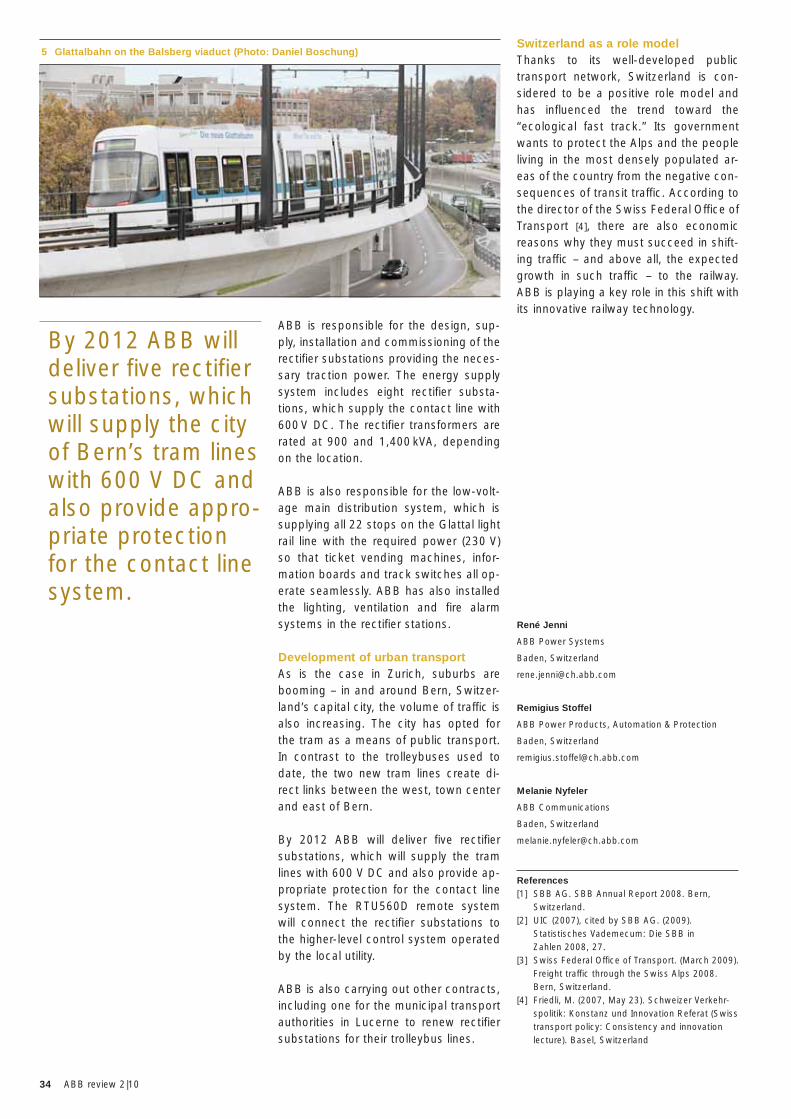
34 ABB review 2|10
ABB is responsible for the design, sup-ply, installation and commissioning of the rectifier substations providing the neces-sary traction power. The energy supply system includes eight rectifier substa-tions, which supply the contact line with 600 V DC. The rectifier transformers are rated at 900 and 1,400 kVA, depending on the location.
ABB is also responsible for the low-volt-age main distribution system, which is supplying all 22 stops on the Glattal light rail line with the required power (230 V) so that ticket vending machines, infor-mation boards and track switches all op-erate seamlessly. ABB has also installed the lighting, ventilation and fire alarm systems in the rectifier stations.
Development of urban transportAs is the case in Zurich, suburbs are booming – in and around Bern, Switzer-land’s capital city, the volume of traffic is also increasing. The city has opted for the tram as a means of public transport. In contrast to the trolleybuses used to date, the two new tram lines create di-rect links between the west, town center and east of Bern.
By 2012 ABB will deliver five rectifier substations, which will supply the tram lines with 600 V DC and also provide ap-propriate protection for the contact line system. The RTU560D remote system will connect the rectifier substations to the higher-level control system operated by the local utility.
ABB is also carrying out other contracts, including one for the municipal transport authorities in Lucerne to renew rectifier substations for their trolleybus lines.
5 Glattalbahn on the Balsberg viaduct (Photo: Daniel Boschung)
By 2012 ABB will deliver five rectifier substations, which will supply the city of Bern’s tram lines with 600 V DC and also provide appro-priate protection for the contact line system.
Switzerland as a role modelThanks to its well-developed public transport network, Switzerland is con-sidered to be a positive role model and has influenced the trend toward the “ecological fast track.” Its government wants to protect the Alps and the people living in the most densely populated ar-eas of the country from the negative con-sequences of transit traffic. According to the director of the Swiss Federal Office of Transport [4], there are also economic reasons why they must succeed in shift-ing traffic – and above all, the expected growth in such traffic – to the railway. ABB is playing a key role in this shift with its innovative railway technology.
René Jenni
ABB Power Systems
Baden, Switzerland
Remigius Stoffel
ABB Power Products, Automation & Protection
Baden, Switzerland
Melanie Nyfeler
ABB Communications
Baden, Switzerland
References[1] SBB AG. SBB Annual Report 2008. Bern,
Switzerland.[2] UIC (2007), cited by SBB AG. (2009).
Statistisches Vademecum: Die SBB in Zahlen 2008, 27.
[3] Swiss Federal Office of Transport. (March 2009). Freight traffic through the Swiss Alps 2008. Bern, Switzerland.
[4] Friedli, M. (2007, May 23). Schweizer Verkehr-spolitik: Konstanz und Innovation Referat (Swiss transport policy: Consistency and innovation lecture). Basel, Switzerland
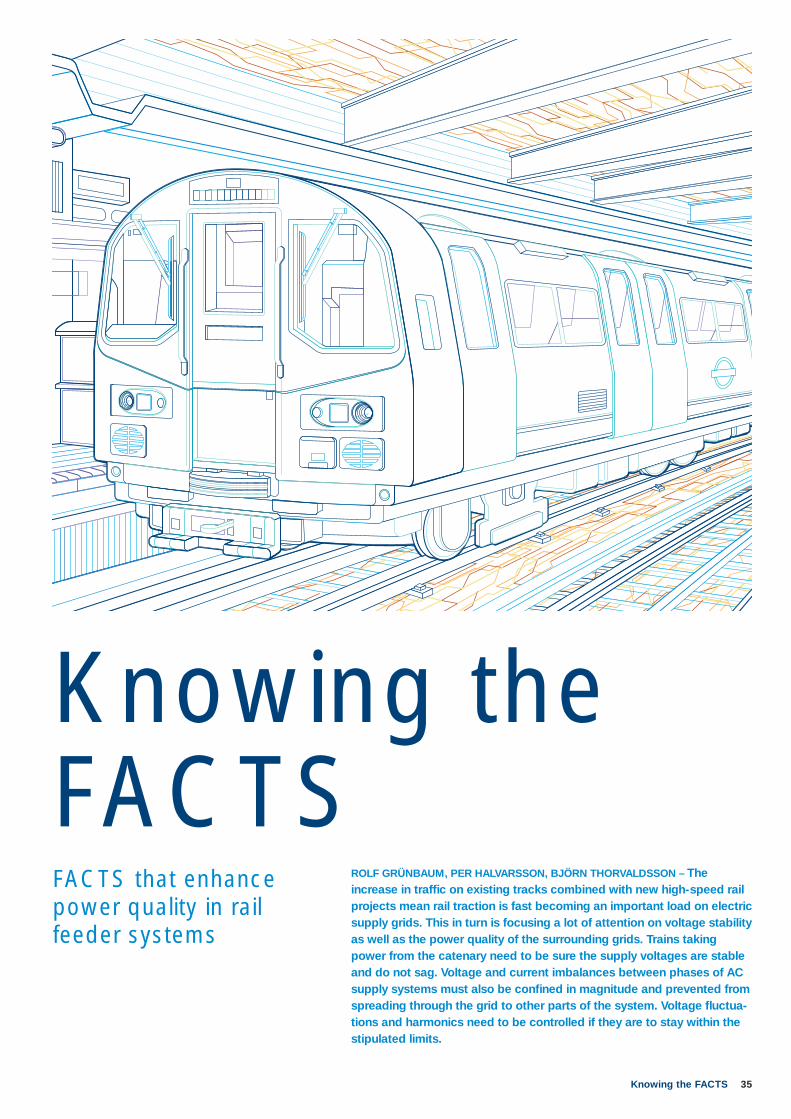
35Knowing the FACTS
ROLF GRÜNBAUM, PER HALVARSSON, BJÖRN THORVALDSSON – The increase in traffi c on existing tracks combined with new high-speed rail projects mean rail traction is fast becoming an important load on electric supply grids. This in turn is focusing a lot of attention on voltage stability as well as the power quality of the surrounding grids. Trains taking power from the catenary need to be sure the supply voltages are stable and do not sag. Voltage and current imbalances between phases of AC supply systems must also be confi ned in magnitude and prevented from spreading through the grid to other parts of the system. Voltage fl uctua-tions and harmonics need to be controlled if they are to stay within the stipulated limits.
Knowing the FACTSFACTS that enhance power quality in rail feeder systems
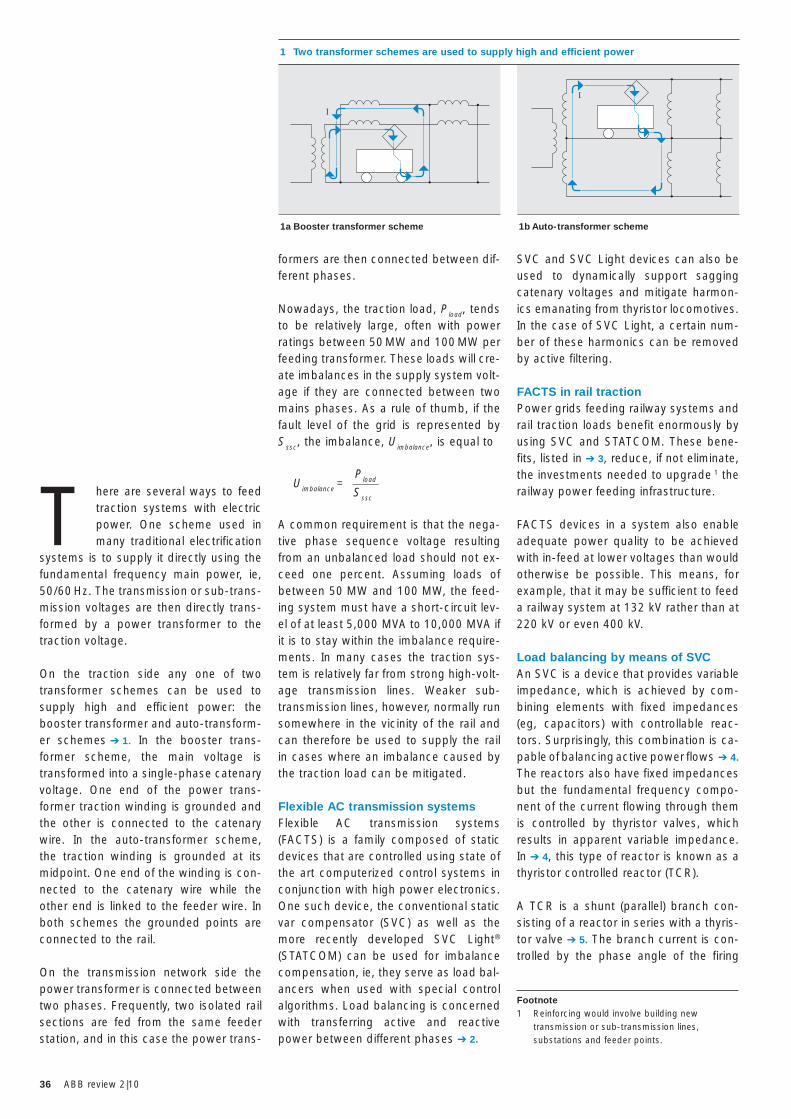
36 ABB review 2|10
SVC and SVC Light devices can also be used to dynamically support sagging catenary voltages and mitigate harmon-ics emanating from thyristor locomotives. In the case of SVC Light, a certain num-ber of these harmonics can be removed by active filtering.
FACTS in rail tractionPower grids feeding railway systems and rail traction loads benefit enormously by using SVC and STATCOM. These bene-fits, listed in ➔ 3, reduce, if not eliminate, the investments needed to upgrade 1 the railway power feeding infrastructure.
FACTS devices in a system also enable adequate power quality to be achieved with in-feed at lower voltages than would otherwise be possible. This means, for example, that it may be sufficient to feed a railway system at 132 kV rather than at 220 kV or even 400 kV.
Load balancing by means of SVCAn SVC is a device that provides variable impedance, which is achieved by com-bining elements with fixed impedances (eg, capacitors) with controllable reac-tors. Surprisingly, this combination is ca-pable of balancing active power flows ➔ 4. The reactors also have fixed impedances but the fundamental frequency compo-nent of the current flowing through them is controlled by thyristor valves, which results in apparent variable impedance. In ➔ 4, this type of reactor is known as a thyristor controlled reactor (TCR).
A TCR is a shunt (parallel) branch con-sisting of a reactor in series with a thyris-tor valve ➔ 5. The branch current is con-trolled by the phase angle of the firing
formers are then connected between dif-ferent phases.
Nowadays, the traction load, Pload, tends to be relatively large, often with power ratings between 50 MW and 100 MW per feeding transformer. These loads will cre-ate imbalances in the supply system volt-age if they are connected between two mains phases. As a rule of thumb, if the fault level of the grid is represented by Sssc, the imbalance, Uimbalance, is equal to
A common requirement is that the nega-tive phase sequence voltage resulting from an unbalanced load should not ex-ceed one percent. Assuming loads of between 50 MW and 100 MW, the feed-ing system must have a short-circuit lev-el of at least 5,000 MVA to 10,000 MVA if it is to stay within the imbalance require-ments. In many cases the traction sys-tem is relatively far from strong high-volt-age transmission lines. Weaker sub-transmission lines, however, normally run somewhere in the vicinity of the rail and can therefore be used to supply the rail in cases where an imbalance caused by the traction load can be mitigated.
Flexible AC transmission systemsFlexible AC transmission systems (FACTS) is a family composed of static devices that are controlled using state of the art computerized control systems in conjunction with high power electronics. One such device, the conventional static var compensator (SVC) as well as the more recently developed SVC Light® (STATCOM) can be used for imbalance compensation, ie, they serve as load bal-ancers when used with special control algorithms. Load balancing is concerned with transferring active and reactive power between different phases ➔ 2.
T here are several ways to feed traction systems with electric power. One scheme used in many traditional electrification
systems is to supply it directly using the fundamental frequency main power, ie, 50/60 Hz. The transmission or sub-trans-mission voltages are then directly trans-formed by a power transformer to the traction voltage.
On the traction side any one of two transformer schemes can be used to supply high and efficient power: the booster transformer and auto-transform-er schemes ➔ 1. In the booster trans-former scheme, the main voltage is transformed into a single-phase catenary voltage. One end of the power trans-former traction winding is grounded and the other is connected to the catenary wire. In the auto-transformer scheme, the traction winding is grounded at its midpoint. One end of the winding is con-nected to the catenary wire while the other end is linked to the feeder wire. In both schemes the grounded points are connected to the rail.
On the transmission network side the power transformer is connected between two phases. Frequently, two isolated rail sections are fed from the same feeder station, and in this case the power trans-
1 Two transformer schemes are used to supply high and efficient power
I
I
1a Booster transformer scheme 1b Auto-transformer scheme
Uimbalance =
Pload
Sssc
Footnote1 Reinforcing would involve building new
transmission or sub-transmission lines, substations and feeder points.
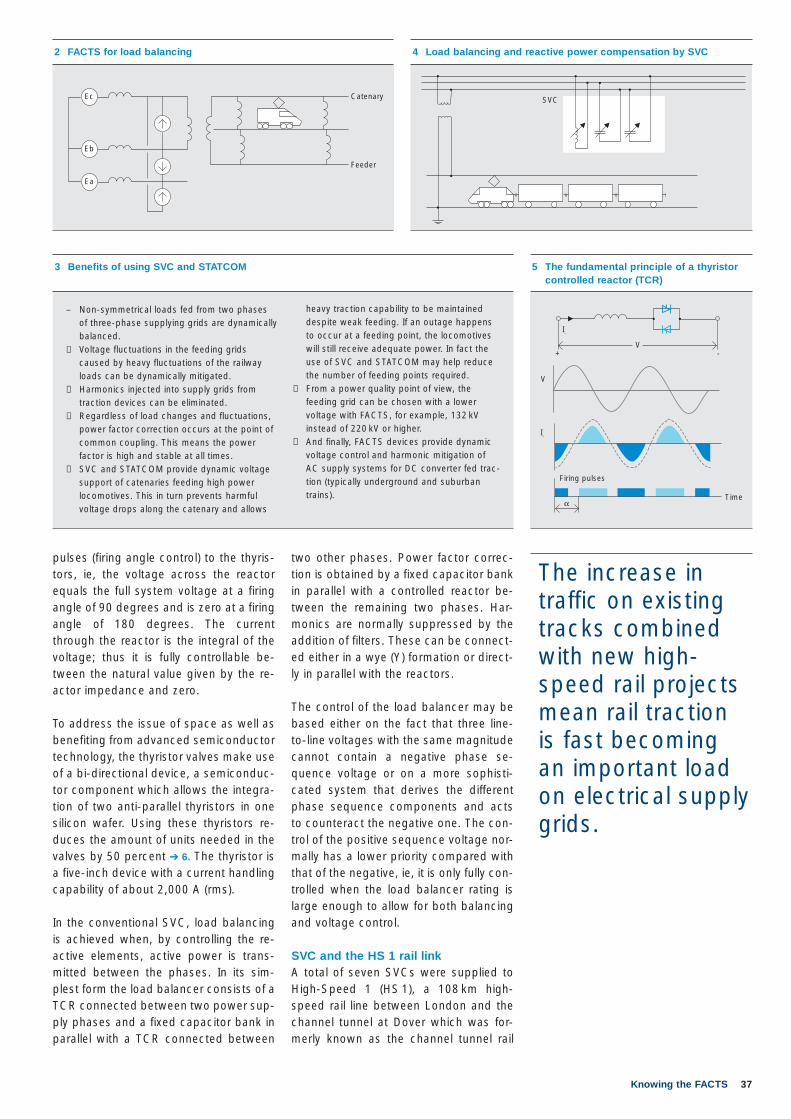
37Knowing the FACTS
two other phases. Power factor correc-tion is obtained by a fixed capacitor bank in parallel with a controlled reactor be-tween the remaining two phases. Har-monics are normally suppressed by the addition of filters. These can be connect-ed either in a wye (Y) formation or direct-ly in parallel with the reactors.
The control of the load balancer may be based either on the fact that three line-to-line voltages with the same magnitude cannot contain a negative phase se-quence voltage or on a more sophisti-cated system that derives the different phase sequence components and acts to counteract the negative one. The con-trol of the positive sequence voltage nor-mally has a lower priority compared with that of the negative, ie, it is only fully con-trolled when the load balancer rating is large enough to allow for both balancing and voltage control.
SVC and the HS 1 rail linkA total of seven SVCs were supplied to High-Speed 1 (HS 1), a 108 km high-speed rail line between London and the channel tunnel at Dover which was for-merly known as the channel tunnel rail
pulses (firing angle control) to the thyris-tors, ie, the voltage across the reactor equals the full system voltage at a firing angle of 90 degrees and is zero at a firing angle of 180 degrees. The current through the reactor is the integral of the voltage; thus it is fully controllable be-tween the natural value given by the re-actor impedance and zero. To address the issue of space as well as benefiting from advanced semiconductor technology, the thyristor valves make use of a bi-directional device, a semiconduc-tor component which allows the integra-tion of two anti-parallel thyristors in one silicon wafer. Using these thyristors re-duces the amount of units needed in the valves by 50 percent ➔ 6. The thyristor is a five-inch device with a current handling capability of about 2,000 A (rms). In the conventional SVC, load balancing is achieved when, by controlling the re-active elements, active power is trans-mitted between the phases. In its sim-plest form the load balancer consists of a TCR connected between two power sup-ply phases and a fixed capacitor bank in parallel with a TCR connected between
2 FACTS for load balancing
Catenary
Feeder
Ec
Eb
Ea
5 The fundamental principle of a thyristor controlled reactor (TCR)
I-
I-
V
V
Firing pulses
Timeα
+ -
3 Benefits of using SVC and STATCOM
– Non-symmetrical loads fed from two phases of three-phase supplying grids are dynamically balanced.
− Voltage fluctuations in the feeding grids caused by heavy fluctuations of the railway loads can be dynamically mitigated.
− Harmonics injected into supply grids from traction devices can be eliminated.
− Regardless of load changes and fluctuations, power factor correction occurs at the point of common coupling. This means the power factor is high and stable at all times.
− SVC and STATCOM provide dynamic voltage support of catenaries feeding high power locomotives. This in turn prevents harmful voltage drops along the catenary and allows
The increase in traffic on existing tracks combined with new high-speed rail projects mean rail traction is fast becoming an important load on electrical supply grids.
heavy traction capability to be maintained despite weak feeding. If an outage happens to occur at a feeding point, the locomotives will still receive adequate power. In fact the use of SVC and STATCOM may help reduce the number of feeding points required.
− From a power quality point of view, the feeding grid can be chosen with a lower voltage with FACTS, for example, 132 kV instead of 220 kV or higher.
− And finally, FACTS devices provide dynamic voltage control and harmonic mitigation of AC supply systems for DC converter fed trac-tion (typically underground and suburban trains).
4 Load balancing and reactive power compensation by SVC
SVC
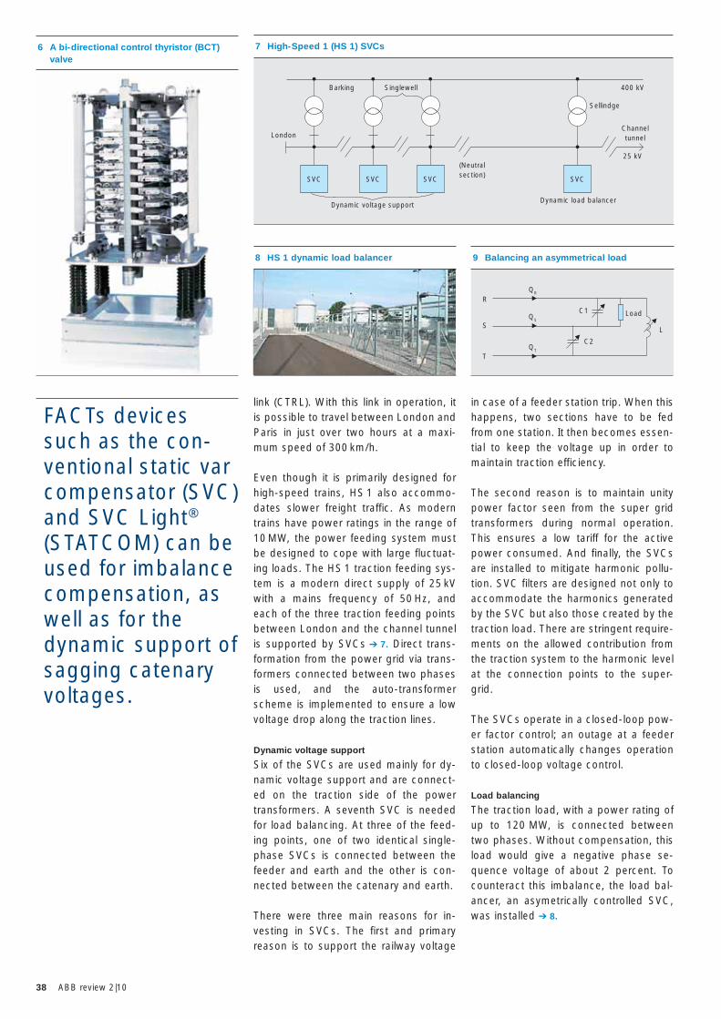
38 ABB review 2|10
in case of a feeder station trip. When this happens, two sections have to be fed from one station. It then becomes essen-tial to keep the voltage up in order to maintain traction efficiency.
The second reason is to maintain unity power factor seen from the super grid transformers during normal operation. This ensures a low tariff for the active power consumed. And finally, the SVCs are installed to mitigate harmonic pollu-tion. SVC filters are designed not only to accommodate the harmonics generated by the SVC but also those created by the traction load. There are stringent require-ments on the allowed contribution from the traction system to the harmonic level at the connection points to the super-grid.
The SVCs operate in a closed-loop pow-er factor control; an outage at a feeder station automatically changes operation to closed-loop voltage control.
Load balancing
The traction load, with a power rating of up to 120 MW, is connected between two phases. Without compensation, this load would give a negative phase se-quence voltage of about 2 percent. To counteract this imbalance, the load bal-ancer, an asymetrically controlled SVC, was installed ➔ 8.
link (CTRL). With this link in operation, it is possible to travel between London and Paris in just over two hours at a maxi-mum speed of 300 km/h.
Even though it is primarily designed for high-speed trains, HS 1 also accommo-dates slower freight traffic. As modern trains have power ratings in the range of 10 MW, the power feeding system must be designed to cope with large fluctuat-ing loads. The HS 1 traction feeding sys-tem is a modern direct supply of 25 kV with a mains frequency of 50 Hz, and each of the three traction feeding points between London and the channel tunnel is supported by SVCs ➔ 7. Direct trans-formation from the power grid via trans-formers connected between two phases is used, and the auto-transformer scheme is implemented to ensure a low voltage drop along the traction lines.
Dynamic voltage support
Six of the SVCs are used mainly for dy-namic voltage support and are connect-ed on the traction side of the power transformers. A seventh SVC is needed for load balancing. At three of the feed-ing points, one of two identical single-phase SVCs is connected between the feeder and earth and the other is con-nected between the catenary and earth.
There were three main reasons for in-vesting in SVCs. The first and primary reason is to support the railway voltage
8 HS 1 dynamic load balancer
7 High-Speed 1 (HS 1) SVCs
Barking
Dynamic voltage supportDynamic load balancer
Singlewell 400 kV
25 kV
Sellindge
London
(Neutralsection)
Channeltunnel
SVC SVC SVC SVC
FACTs devices such as the con-ventional static var compensator (SVC) and SVC Light® (STATCOM) can be used for imbalance compensation, as well as for the dynamic support of sagging catenary voltages.
6 A bi-directional control thyristor (BCT) valve
9 Balancing an asymmetrical load
Load
RQR
QS
C1
C2QT
SL
T
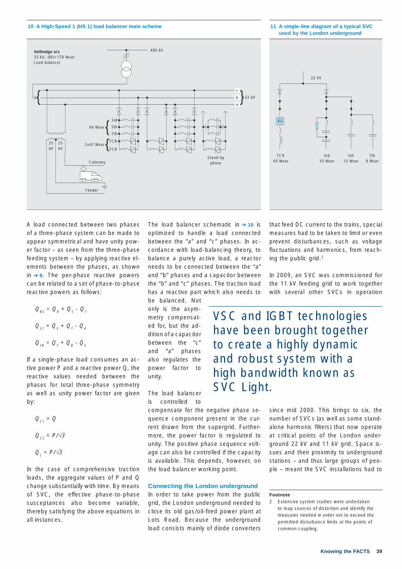
39Knowing the FACTS
that feed DC current to the trains, special measures had to be taken to limit or even prevent disturbances, such as voltage fluctuations and harmonics, from reach-ing the public grid.2
In 2009, an SVC was commissioned for the 11 kV feeding grid to work together with several other SVCs in operation
since mid 2000. This brings to six, the number of SVCs (as well as some stand-alone harmonic filters) that now operate at critical points of the London under-ground 22 kV and 11 kV grid. Space is-sues and their proximity to underground stations – and thus large groups of peo-ple – meant the SVC installations had to
The load balancer schematic in ➔ 10 is optimized to handle a load connected between the “a” and “c” phases. In ac-cordance with load-balancing theory, to balance a purely active load, a reactor needs to be connected between the “a” and “b” phases and a capacitor between the “b” and “c” phases. The traction load has a reactive part which also needs to be balanced. Not only is the asym-metry compensat-ed for, but the ad-dition of a capacitor between the “c” and “a” phases also regulates the power factor to unity. The load balancer is controlled to compensate for the negative phase se-quence component present in the cur-rent drawn from the supergrid. Further-more, the power factor is regulated to unity. The positive phase sequence volt-age can also be controlled if the capacity is available. This depends, however, on the load balancer working point.
Connecting the London undergroundIn order to take power from the public grid, the London underground needed to close its old gas/oil-fired power plant at Lots Road. Because the underground load consists mainly of diode converters
A load connected between two phases of a three-phase system can be made to appear symmetrical and have unity pow-er factor – as seen from the three-phase feeding system – by applying reactive el-ements between the phases, as shown in ➔ 9. The per-phase reactive powers can be related to a set of phase-to-phase reactive powers as follows:
QRS = QR + QS - QT
QST = QS + QT - QR
QTR = QT + QR - QS
If a single-phase load consumes an ac-tive power P and a reactive power Q, the reactive values needed between the phases for total three-phase symmetry as well as unity power factor are given by:
QC1 = Q
QC2 = P/√3
QL = P/√3
In the case of comprehensive traction loads, the aggregate values of P and Q change substantially with time. By means of SVC, the effective phase-to-phase susceptances also become variable, thereby satisfying the above equations in all instances.
11 A single-line diagram of a typical SVC used by the London underground
VSC and IGBT technologies have been brought together to create a highly dynamic and robust system with a high bandwidth known as SVC Light.
Footnote2 Extensive system studies were undertaken
to map sources of distortion and identify the measures needed in order not to exceed the permitted disturbance limits at the points of common coupling.
22 kV
TCR60 Mvar
3rd10 Mvar
5th15 Mvar
7th8 Mvar
10 A High-Speed 1 (HS 1) load balancer main scheme
CatenaryStand-by
phase
Feeder
25 kV
25 kV
400 kVSellindge s/s33 kV, -80/+170 MvarLoad balancer
33 kV}}
}}
84 Mvar
3rd
5th
7th
TCR
TCR2x42 Mvar
a
b
c
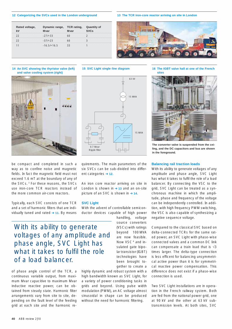
40 ABB review 2|10
be compact and completed in such a way as to confine noise and magnetic fields. In fact the magnetic field must not exceed 1.6 mT at the boundary of any of the SVCs. 3 For these reasons, the SVCs use iron-core TCR reactors instead of the more common air-core reactors.
Typically, each SVC consists of one TCR and a set of harmonic filters that are indi-vidually tuned and rated ➔ 11. By means
of phase angle control of the TCR, a continuous variable output, from maxi-mum Mvar capacitive to maximum Mvar inductive reactive power, can be ob-tained from steady state. Harmonic filter arrangements vary from site to site, de-pending on the fault level of the feeding grid at each site and the harmonic re-
Balancing rail traction loadsWith its ability to generate voltages of any amplitude and phase angle, SVC Light has what it takes to fulfil the role of a load balancer. By connecting the VSC to the grid, SVC Light can be treated as a syn-chronous machine in which the ampli-tude, phase and frequency of the voltage can be independently controlled. In addi-tion, with high frequency PWM switching, the VSC is also capable of synthesizing a negative sequence voltage.
Compared to the classical SVC based on delta-connected TCRs for the same rat-ed power, an SVC Light with phase-wise connected valves and a common DC link can compensate a train load that is √3 times larger. The delta-type connection is less efficent for balancing unsymmetri-cal active power than it is for symmetri-cal reactive power compensation. This difference does not exist if a phase-wise connection is used.
Two SVC Light installations are in opera-tion in the French railway system. Both are fed from the national power grid, one at 90 kV and the other at 63 kV sub-transmission levels. At both sites, SVC
quirements. The main parameters of the six SVCs can be sub-divided into differ-ent categories ➔ 12.
An iron core reactor arriving on site in London is shown in ➔ 13 and an on-site picture of an SVC is shown in ➔ 14.
SVC Light With the advent of controllable semicon-ductor devices capable of high power
handling, voltage source converters (VSCs) with ratings beyond 100 MVA are now feasible. Now VSC 4 and in-sulated gate bipo-lar transistor (IGBT) technologies have been brought to-gether to create a
highly dynamic and robust system with a high bandwidth known as SVC Light, for a variety of power conditioning tasks in grids and beyond. Using pulse width modulation (PWM), an AC voltage almost sinusoidal in shape can be produced without the need for harmonic filtering.
14 An SVC showing the thyristor valve (left) and valve cooling system (right)
16 The IGBT valve hall at one of the French sites
The converter valve is suspended from the cei-ling, and the DC capacitors and bus are shown in the foreground.
15 SVC Light single-line diagram
63 kV
15 MVA
15 MVA
0.7 MvarRipple filter
13 The TCR iron-core reactor arriving on site in London12 Categorizing the SVCs used in the London underground
Rated voltage, Dynamic range, TCR rating, Quantity ofkV Mvar Mvar SVCs
22 -27/+33 60 2
22 -37/+23 60 3
11 -16.5/+16.5 33 1
With its ability to generate voltages of any amplitude and phase angle, SVC Light has what it takes to fulfil the role of a load balancer.
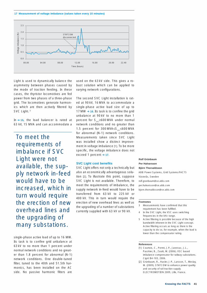
41Knowing the FACTS
Rolf Grünbaum
Per Halvarsson
Björn Thorvaldsson
ABB Power Systems, Grid Systems/FACTS
Västerås, Sweden
Footnotes3 Measurements have confirmed that this
requirement has been fulfilled.4 In the SVC Light, the VSC uses switching
frequencies in the kHz range. 5 Active filtering is possible because of the high
bandwidth inherent in the SVC Light concept. Active filtering occurs as long as there is the capacity to do so, for example, when the load is lower than the compensator rating.
References[1] Courtois, C., Perret, J.P., Javerzac, J.L.,
Paszkier, B., Zouiti, M. (2006). VSC based imbalance compensator for railway substations. Cigré B4-103, 2006.
[2] Grünbaum, R., Hasler, J-P., Larsson, T., Meslay, M. (2009). STATCOM to enhance power quality and security of rail traction supply. ELECTROMOTION 2009, Lille, France.
used on the 63 kV side. This gives a ro-bust solution which can be applied to varying network configurations.
The second SVC Light installation is rat-ed at 90 kV, 16 MVA to accommodate a single-phase active load size of up to 17 MW ➔ 16. Its task is to confine the grid unbalance at 90 kV to no more than 1 percent for Sssc≥600 MVA under normal network conditions and no greater than 1.5 percent for 300 MVA≤Sssc≤600 MVA for abnormal (N-1) network conditions. Measurements taken since SVC Light was installed show a distinct improve-ment in voltage imbalance [1]. To be more specific, the voltage imbalance does not exceed 1 percent ➔ 17.
SVC Light cost benefitsSVC Light offers not only a technically but also an economically advantageous solu-tion [2]. To illustrate this point, suppose SVC Light is not available. Therefore, to meet the requirements of imbalance, the supply network in-feed would have to be transferred from 63 kV to 225 kV or 400 kV. This in turn would require the erection of new overhead lines as well as the upgrading of a number of substations currently supplied with 63 kV or 90 kV.
17 Measurement of voltage imbalance (values taken every 10 minutes)
Time (hours)
Volta
ge im
bal
ance
(%)
STATCOM disconnected
00.00 04.00 08.00 12.00 16.00 20.00 22.40
2.5
2.0
1.5
1.0
0.5
0.0
Light is used to dynamically balance the asymmetry between phases caused by the mode of traction feeding. In these cases, the thyristor locomotives are fed power from two phases of a three-phase grid. The locomotives generate harmon-ics which are then actively filtered by SVC Light. 5
In ➔ 15, the load balancer is rated at 63 kV, 15 MVA and can accommodate a
single-phase active load of up to 16 MW. Its task is to confine grid unbalance at 63 kV to no more than 1 percent under normal network conditions and no great-er than 1.8 percent for abnormal (N-1) network conditions. One double-tuned filter, tuned to the 40th and 51.5th har-monics, has been installed on the AC side. No passive harmonic filters are
To meet the requirements of imbalance if SVC Light were not available, the sup-ply network in-feed would have to be increased, which in turn would require the erection of new overhead lines and the upgrading of many substations.
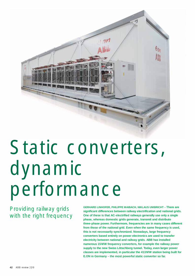
42 ABB review 2|10
GERHARD LINHOFER, PHILIPPE MAIBACH, NIKLAUS UMBRICHT – There are signifi cant differences between railway electrifi cation and national grids. One of these is that AC-electrifi ed railways generally use only a single phase, whereas domestic grids generate, transmit and distribute three-phase power. Furthermore, frequencies are in many cases different from those of the national grid. Even when the same frequency is used, this is not necessarily synchronized. Nowadays, large frequency converters based entirely on power electronics are used to transfer electricity between national and railway grids. ABB has installed numerous 15 MW frequency converters, for example the railway power supply to the new Swiss Lötschberg tunnel. Today, even larger power classes are implemented, in particular the 413 MW station being built for E.ON in Germany – the most powerful static converter so far.
Providing railway grids with the right frequency
Static converters, dynamic performance
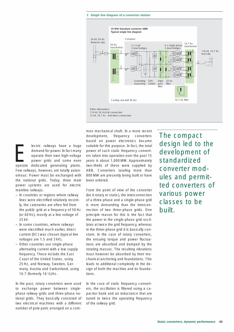
43Static converters, dynamic performance
E lectric railways have a huge demand for power. In fact many operate their own high-voltage power grids and some even
operate dedicated generating plants. Few railways, however, are totally auton-omous: Power must be exchanged with the national grids. Today, three main power systems are used for electric mainline railways. – In countries or regions where railway
lines were electrified relatively recent-ly, the catenaries are often fed from the public grid at a frequency of 50 Hz (or 60 Hz), mostly at a line voltage of 25 kV.
– In some countries, where railways were electrified much earlier, direct current (DC) was chosen (typical line voltages are 1.5 and 3 kV).
– Other countries use single-phase alternating current with a low supply frequency. These include the East Coast of the United States, using 25 Hz, and Norway, Sweden, Ger-many, Austria and Switzerland, using 16.7 (formerly 16 2/3) Hz.
In the past, rotary converters were used to exchange power between single-phase railway grids and three-phase na-tional grids. They basically consisted of two electrical machines with a different number of pole pairs arranged on a com-
mon mechanical shaft. In a more recent development, frequency converters based on power electronics became suitable for this purpose. In fact, the total power of such static frequency convert-ers taken into operation over the past 15 years is about 1,000 MW. Approximately two-thirds of these were supplied by ABB. Converters totaling more than 800 MW are presently being built or have been ordered.
From the point of view of the converter (be it rotary or static), the interconnection of a three-phase and a single-phase grid is more demanding than the intercon-nection of two three-phase grids. One principle reason for this is the fact that the power in the single-phase grid oscil-lates at twice the grid frequency, whereas in the three-phase grid it is basically con-stant. In the case of rotary converters, the ensuing torque and power fluctua-tions are absorbed and damped by the rotating masses. The resulting vibrations must however be absorbed by their me-chanical anchoring and foundations. This leads to additional complexity in the de-sign of both the machine and its founda-tions.
In the case of static frequency convert-ers, the oscillation is filtered using a ca-pacitor bank and an inductance that are tuned to twice the operating frequency of the railway grid.
The compact design led to the development of standardized converter mod-ules and permit-ted converters of various power classes to be built.
3 3
3
2
1
1 Single line diagram of a converter station
20 kV, 50 HzNetwork side
50 Hz transformer
2 x 3-ph3-level bridges
Groundingmeasuring
UZK-Limiter
High-passfilter
16.7 Hz filterCooling unit with fin fan
Other alternatives:110 kV, 50 Hz Grid connection 15 kV, 16.7 Hz Rail direct connection
33 Hzfilter
4 x single phase3-level bridges
16.7 Hz transformer
110 kV, 16.7 HzRail side
Container
15 MW Standard converter ABBTypical single line diagram
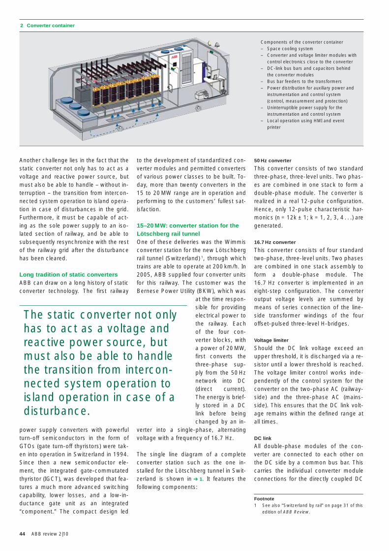
44 ABB review 2|10
50 Hz converter
This converter consists of two standard three-phase, three-level units. Two phas-es are combined in one stack to form a double-phase module. The converter is realized in a real 12-pulse configuration. Hence, only 12-pulse characteristic har-monics (n = 12k ± 1; k = 1, 2, 3, 4 . . .) are generated.
16.7 Hz converter
This converter consists of four standard two-phase, three-level units. Two phases are combined in one stack assembly to form a double-phase module. The 16.7 Hz converter is implemented in an eight-step configuration. The converter output voltage levels are summed by means of series connection of the line-side transformer windings of the four offset-pulsed three-level H-bridges.
Voltage limiter
Should the DC link voltage exceed an upper threshold, it is discharged via a re-sistor until a lower threshold is reached. The voltage limiter control works inde-pendently of the control system for the converter on the two-phase AC (railway-side) and the three-phase AC (mains-side). This ensures that the DC link volt-age remains within the defined range at all times.
DC link
All double-phase modules of the con-verter are connected to each other on the DC side by a common bus bar. This carries the individual converter module connections for the directly coupled DC
to the development of standardized con-verter modules and permitted converters of various power classes to be built. To-day, more than twenty converters in the 15 to 20 MW range are in operation and performing to the customers’ fullest sat-isfaction.
15–20 MW: converter station for the Lötschberg rail tunnelOne of these deliveries was the Wimmis converter station for the new Lötschberg rail tunnel (Switzerland) 1, through which trains are able to operate at 200 km/h. In 2005, ABB supplied four converter units for this railway. The customer was the Bernese Power Utility (BKW), which was
at the time respon-sible for providing electrical power to the railway. Each of the four con-verter blocks, with a power of 20 MW, first converts the three-phase sup-ply from the 50 Hz network into DC (direct current). The energy is brief-ly stored in a DC link before being changed by an in-
verter into a single-phase, alternating voltage with a frequency of 16.7 Hz.
The single line diagram of a complete converter station such as the one in-stalled for the Lötschberg tunnel in Swit-zerland is shown in ➔ 1. It features the following components:
Another challenge lies in the fact that the static converter not only has to act as a voltage and reactive power source, but must also be able to handle – without in-terruption – the transition from intercon-nected system operation to island opera-tion in case of disturbances in the grid. Furthermore, it must be capable of act-ing as the sole power supply to an iso-lated section of railway, and be able to subsequently resynchronize with the rest of the railway grid after the disturbance has been cleared.
Long tradition of static convertersABB can draw on a long history of static converter technology. The first railway
power supply converters with powerful turn-off semiconductors in the form of GTOs (gate turn-off thyristors) were tak-en into operation in Switzerland in 1994. Since then a new semiconductor ele-ment, the integrated gate-commutated thyristor (IGCT), was developed that fea-tures a much more advanced switching capability, lower losses, and a low-in-ductance gate unit as an integrated “component.” The compact design led
2 Converter container
Components of the converter container– Space cooling system– Converter and voltage limiter modules with
control electronics close to the converter– DC-link bus bars and capacitors behind
the converter modules– Bus bar feeders to the transformers– Power distribution for auxiliary power and
instrumentation and control system (control, measurement and protection)
– Uninterruptible power supply for the instrumentation and control system
– Local operation using HMI and event printer
The static converter not only has to act as a voltage and reactive power source, but must also be able to handle the transition from intercon-nected system operation to island operation in case of a disturbance.
Footnote1 See also “Switzerland by rail” on page 31 of this
edition of ABB Review.
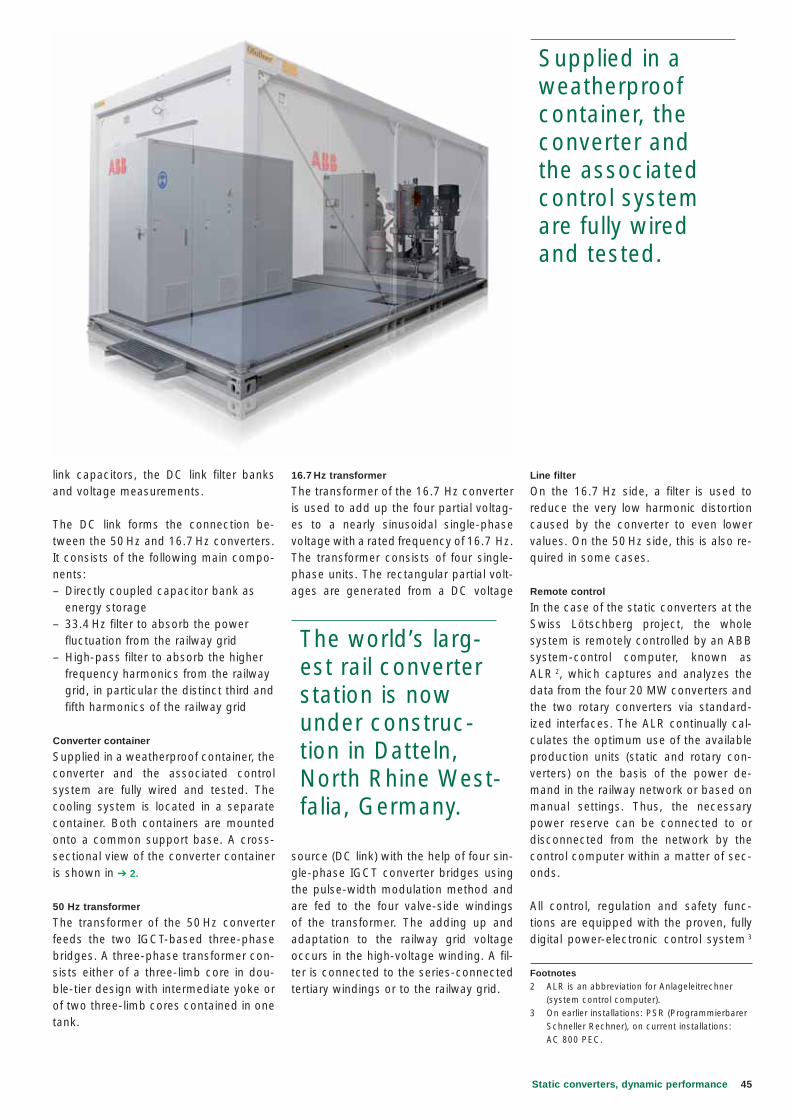
45Static converters, dynamic performance
Line filter
On the 16.7 Hz side, a filter is used to reduce the very low harmonic distortion caused by the converter to even lower values. On the 50 Hz side, this is also re-quired in some cases.
Remote control
In the case of the static converters at the Swiss Lötschberg project, the whole system is remotely controlled by an ABB system-control computer, known as ALR 2, which captures and analyzes the data from the four 20 MW converters and the two rotary converters via standard-ized interfaces. The ALR continually cal-culates the optimum use of the available production units (static and rotary con-verters) on the basis of the power de-mand in the railway network or based on manual settings. Thus, the necessary power reserve can be connected to or disconnected from the network by the control computer within a matter of sec-onds.
All control, regulation and safety func-tions are equipped with the proven, fully digital power-electronic control system 3
16.7 Hz transformer
The transformer of the 16.7 Hz converter is used to add up the four partial voltag-es to a nearly sinusoidal single-phase voltage with a rated frequency of 16.7 Hz. The transformer consists of four single-phase units. The rectangular partial volt-ages are generated from a DC voltage
source (DC link) with the help of four sin-gle-phase IGCT converter bridges using the pulse-width modulation method and are fed to the four valve-side windings of the transformer. The adding up and adaptation to the railway grid voltage occurs in the high-voltage winding. A fil-ter is connected to the series-connected tertiary windings or to the railway grid.
link capacitors, the DC link filter banks and voltage measurements.
The DC link forms the connection be-tween the 50 Hz and 16.7 Hz converters. It consists of the following main compo-nents:– Directly coupled capacitor bank as
energy storage– 33.4 Hz filter to absorb the power
fluctuation from the railway grid– High-pass filter to absorb the higher
frequency harmonics from the railway grid, in particular the distinct third and fifth harmonics of the railway grid
Converter container
Supplied in a weatherproof container, the converter and the associated control system are fully wired and tested. The cooling system is located in a separate container. Both containers are mounted onto a common support base. A cross-sectional view of the converter container is shown in ➔ 2.
50 Hz transformer
The transformer of the 50 Hz converter feeds the two IGCT-based three-phase bridges. A three-phase transformer con-sists either of a three-limb core in dou-ble-tier design with intermediate yoke or of two three-limb cores contained in one tank.
Footnotes2 ALR is an abbreviation for Anlageleitrechner
(system control computer).3 On earlier installations: PSR (Programmierbarer
Schneller Rechner), on current installations: AC 800 PEC.
The world’s larg-est rail converter station is now under construc-tion in Datteln, North Rhine West-falia, Germany.
Supplied in a weatherproof container, the converter and the associated control system are fully wired and tested.
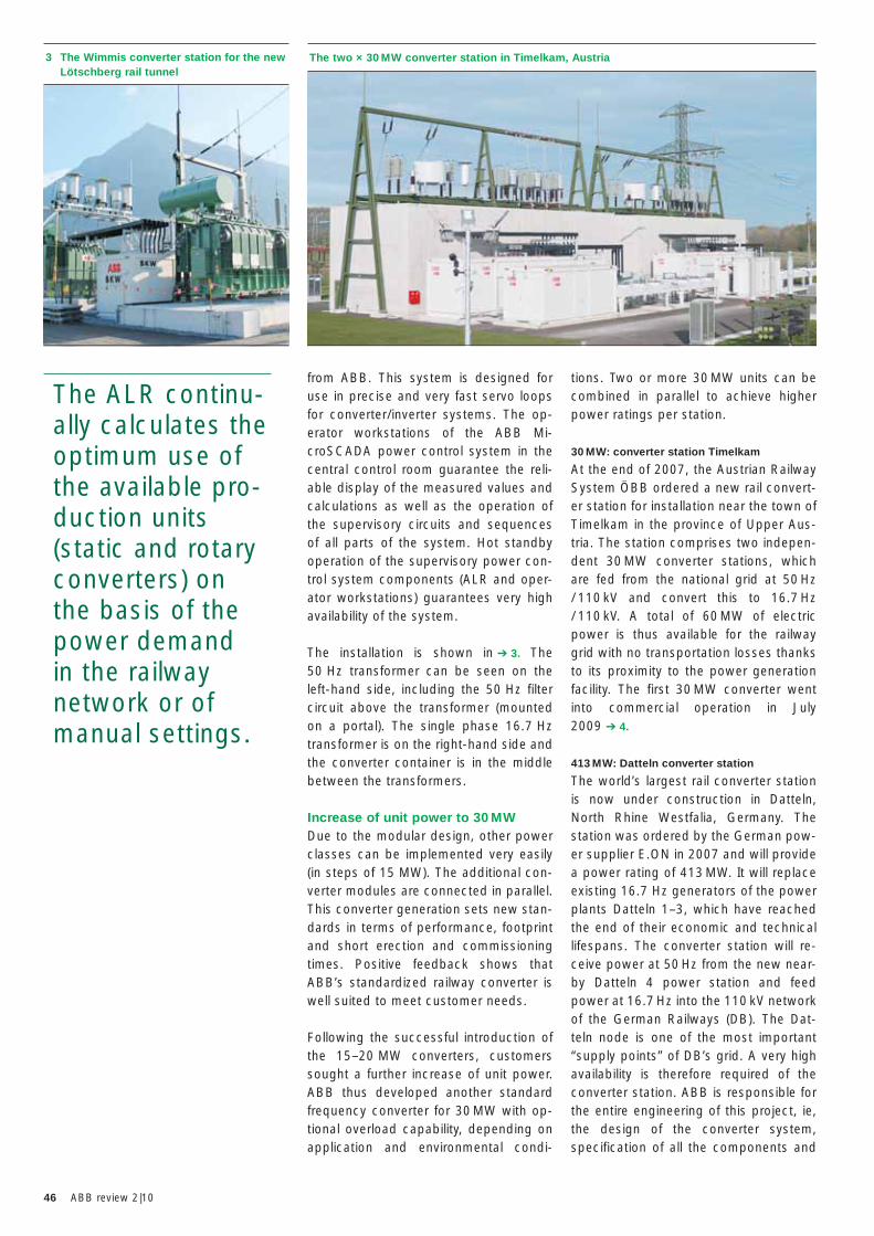
46 ABB review 2|10
tions. Two or more 30 MW units can be combined in parallel to achieve higher power ratings per station.
30 MW: converter station Timelkam
At the end of 2007, the Austrian Railway System ÖBB ordered a new rail convert-er station for installation near the town of Timelkam in the province of Upper Aus-tria. The station comprises two indepen-dent 30 MW converter stations, which are fed from the national grid at 50 Hz / 110 kV and convert this to 16.7 Hz / 110 kV. A total of 60 MW of electric power is thus available for the railway grid with no transportation losses thanks to its proximity to the power generation facility. The first 30 MW converter went into commercial operation in July 2009 ➔ 4.
413 MW: Datteln converter station
The world’s largest rail converter station is now under construction in Datteln, North Rhine Westfalia, Germany. The station was ordered by the German pow-er supplier E.ON in 2007 and will provide a power rating of 413 MW. It will replace existing 16.7 Hz generators of the power plants Datteln 1–3, which have reached the end of their economic and technical lifespans. The converter station will re-ceive power at 50 Hz from the new near-by Datteln 4 power station and feed power at 16.7 Hz into the 110 kV network of the German Railways (DB). The Dat-teln node is one of the most important “supply points” of DB’s grid. A very high availability is therefore required of the converter station. ABB is responsible for the entire engineering of this project, ie, the design of the converter system, specification of all the components and
from ABB. This system is designed for use in precise and very fast servo loops for converter/inverter systems. The op-erator workstations of the ABB Mi-croSCADA power control system in the central control room guarantee the reli-able display of the measured values and calculations as well as the operation of the supervisory circuits and sequences of all parts of the system. Hot standby operation of the supervisory power con-trol system components (ALR and oper-ator workstations) guarantees very high availability of the system.
The installation is shown in ➔ 3. The 50 Hz transformer can be seen on the left-hand side, including the 50 Hz filter circuit above the transformer (mounted on a portal). The single phase 16.7 Hz transformer is on the right-hand side and the converter container is in the middle between the transformers.
Increase of unit power to 30 MWDue to the modular design, other power classes can be implemented very easily (in steps of 15 MW). The additional con-verter modules are connected in parallel. This converter generation sets new stan-dards in terms of performance, footprint and short erection and commissioning times. Positive feedback shows that ABB’s standardized railway converter is well suited to meet customer needs.
Following the successful introduction of the 15–20 MW converters, customers sought a further increase of unit power. ABB thus developed another standard frequency converter for 30 MW with op-tional overload capability, depending on application and environmental condi-
3 The Wimmis converter station for the new Lötschberg rail tunnel
The ALR continu-ally calculates the optimum use of the available pro-duction units (static and rotary converters) on the basis of the power demand in the railway network or of manual settings.
The two × 30 MW converter station in Timelkam, Austria
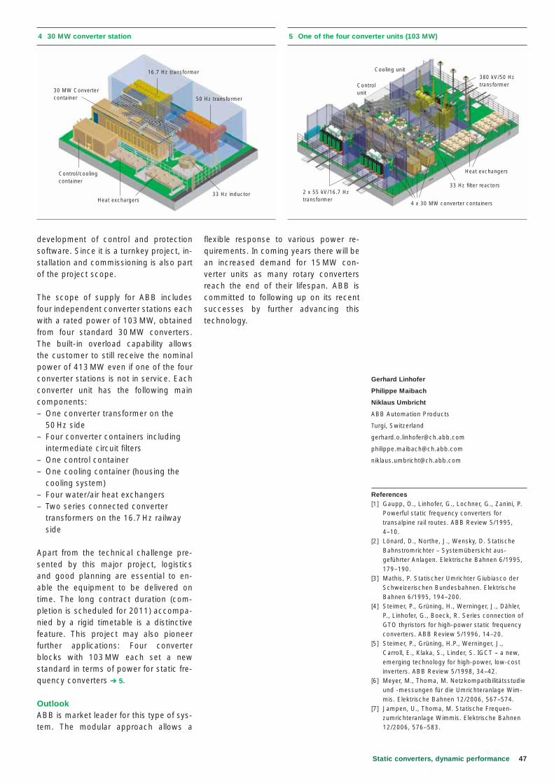
47Static converters, dynamic performance
flexible response to various power re-quirements. In coming years there will be an increased demand for 15 MW con-verter units as many rotary converters reach the end of their lifespan. ABB is committed to following up on its recent successes by further advancing this technology.
development of control and protection software. Since it is a turnkey project, in-stallation and commissioning is also part of the project scope.
The scope of supply for ABB includes four independent converter stations each with a rated power of 103 MW, obtained from four standard 30 MW converters. The built-in overload capability allows the customer to still receive the nominal power of 413 MW even if one of the four converter stations is not in service. Each converter unit has the following main components:– One converter transformer on the
50 Hz side – Four converter containers including
intermediate circuit filters– One control container– One cooling container (housing the
cooling system)– Four water/air heat exchangers– Two series connected converter
transformers on the 16.7 Hz railway side
Apart from the technical challenge pre-sented by this major project, logistics and good planning are essential to en-able the equipment to be delivered on time. The long contract duration (com-pletion is scheduled for 2011) accompa-nied by a rigid timetable is a distinctive feature. This project may also pioneer further applications: Four converter blocks with 103 MW each set a new standard in terms of power for static fre-quency converters ➔ 5.
OutlookABB is market leader for this type of sys-tem. The modular approach allows a
Gerhard Linhofer
Philippe Maibach
Niklaus Umbricht
ABB Automation Products
Turgi, Switzerland
References[1] Gaupp, O., Linhofer, G., Lochner, G., Zanini, P. Powerful static frequency converters for
transalpine rail routes. ABB Review 5/1995, 4–10.
[2] Lönard, D., Northe, J., Wensky, D. Statische Bahnstromrichter – Systemübersicht aus-
geführter Anlagen. Elektrische Bahnen 6/1995, 179–190.
[3] Mathis, P. Statischer Umrichter Giubiasco der Schweizerischen Bundesbahnen. Elektrische Bahnen 6/1995, 194–200.[4] Steimer, P., Grüning, H., Werninger, J., Dähler, P., Linhofer, G., Boeck, R. Series connection of GTO thyristors for high-power static frequency converters. ABB Review 5/1996, 14–20.[5] Steimer, P., Grüning, H.P., Werninger, J., Carroll, E., Klaka, S., Linder, S. IGCT – a new, emerging technology for high-power, low-cost inverters. ABB Review 5/1998, 34–42.[6] Meyer, M., Thoma, M. Netzkompatibilitätsstudie und -messungen für die Umrichteranlage Wim-
mis. Elektrische Bahnen 12/2006, 567–574.[7] Jampen, U., Thoma, M. Statische Frequen-
zumrichteranlage Wimmis. Elektrische Bahnen 12/2006, 576–583.
4 30 MW converter station
16.7 Hz transformer
50 Hz transformer
Control/cooling container
30 MW Convertercontainer
33 Hz inductorHeat exchargers
5 One of the four converter units (103 MW)
Cooling unit380 kV/50 Hz transformer
Heat exchangers
33 Hz filter reactors
4 x 30 MW converter containers
2 x 55 kV/16.7 Hz transformer
Controlunit
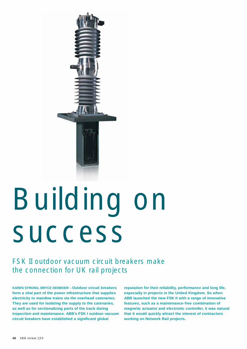
48 ABB review 2|10
FSK II outdoor vacuum circuit breakers make the connection for UK rail projects
KAREN STRONG, BRYCE DENBOER – Outdoor circuit breakers form a vital part of the power infrastructure that supplies electricity to mainline trains via the overhead catenaries. They are used for isolating the supply to the catenaries, as well as for sectionalizing parts of the track during inspection and maintenance. ABB’s FSK I outdoor vacuum circuit breakers have established a significant global
reputation for their reliability, performance and long life, especially in projects in the United Kingdom. So when ABB launched the new FSK II with a range of innovative features, such as a maintenance-free combination of magnetic actuator and electronic controller, it was natural that it would quickly attract the interest of contractors working on Network Rail projects.
Building on success
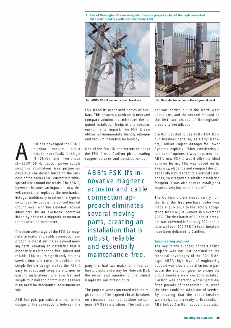
49Building on success
ect was carried out in the North West Leeds area and the second focused on the first two phases of Birmingham’s cross-city electrification.
Carillion decided to use ABB’s FSK II cir-cuit breakers because, as Darryl Hack-ett, Carillion Project Manager for Power Systems explains, “After considering a number of options it was apparent that ABB’s new FSK II would offer the ideal solution for us. This was based on its simplicity, elegance and compact design, especially with respect to electrical clear-ances, so it required a smaller installation footprint. It was also easy to install (and) requires very low maintenance.”
The Carillion project moved swiftly from the time the first purchase order was made in July 2007 to the factory accep-tance test (FAT) in Geneva in November 2007. The first batch of 50 circuit break-ers was delivered in February 200, and to date well over 100 FSK II circuit-breakers have been delivered to Carillion.
Engineering supportThe key to the success of the Carillion projects was not just confined to the technical advantages of the FSK II de-sign; ABB’s high level of engineering support was also a crucial factor, in par-ticular the attention given to ensure the circuit breakers were correctly installed. Carillion was operating within tightly de-fined periods of “possession,” ie, when the sites could be taken out of service. By ensuring that the circuit-breakers were delivered in a ready-to-fit condition, ABB helped Carillion reduce the duration
FSK II and its associated cables or bus-bars. This ensures a particularly neat and compact solution that minimizes the re-quired installation footprint and reduces environmental impact. The FSK II also utilizes environmentally friendly nitrogen and vacuum insulating technology.
One of the first UK contractors to adopt the FSK II was Carillion plc, a leading support services and construction com-
pany that had two major rail infrastruc-ture projects underway for Network Rail, the owner and operator of the United Kingdom’s rail infrastructure.
The projects were concerned with the re-placement of life-expired circuit-breakers on structure mounted outdoor switch-gear (SMOS) installations. The first proj-
A BB has developed the FSK II outdoor vacuum circuit breaker specifically for single (1 × 25 kV) and two-phase
(2 × 25 kV) 50 Hz traction power supply switching applications (see picture on page 48). The design builds on the suc-cess of the earlier FSK I currently in wide-spread use around the world. The FSK II, however, features an important new de-velopment that replaces the mechanical linkage, traditionally used on this type of switchgear to couple the control box (at ground level) with the elevated vacuum interrupter, by an electronic controller linked by cable to a magnetic actuator at the base of the interrupter.
The main advantage of the FSK II’s mag-netic actuator and cable connection ap-proach is that it eliminates several mov-ing parts, creating an installation that is essentially maintenance-free, robust and reliable. This in turn significantly reduces service time and costs. In addition, the simple flexible design makes the FSK II easy to adapt and integrate into new or existing installations. It is also fast and simple to install and commission as there is no need for mechanical adjustment on site.
ABB has paid particular attention to the design of the connections between the
1 Part of Birmingham’s cross-city eletrification project included the replacement of old circuit breakers with new ones from ABB
1a ABB’s FSK II vacuum circuit breakers 1b New electronic controller at ground level
ABB’s FSK II’s in-novative magnetic actuator and cable connection ap-proach eliminates several moving parts, creating an installation that is robust, reliable and essentially maintenance-free.
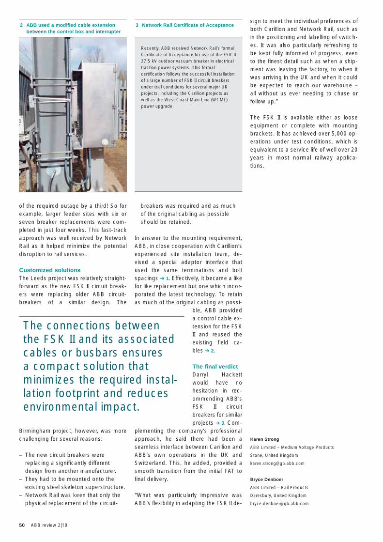
50 ABB review 2|10
sign to meet the individual preferences of both Carillion and Network Rail, such as in the positioning and labelling of switch-es. It was also particularly refreshing to be kept fully informed of progress, even to the finest detail such as when a ship-ment was leaving the factory, to when it was arriving in the UK and when it could be expected to reach our warehouse – all without us ever needing to chase or follow up.”
The FSK II is available either as loose equipment or complete with mounting brackets. It has achieved over 5,000 op-erations under test conditions, which is equivalent to a service life of well over 20 years in most normal railway applica-tions.
Karen Strong
ABB Limited – Medium Voltage Products
Stone, United Kingdom
Bryce Denboer
ABB Limited – Rail Products
Daresbury, United Kingdom
breakers was required and as much of the original cabling as possible should be retained.
In answer to the mounting requirement, ABB, in close cooperation with Carillion’s experienced site installation team, de-vised a special adaptor interface that used the same terminations and bolt spacings ➔ 1. Effectively, it became a like for like replacement but one which incor-porated the latest technology. To retain as much of the original cabling as possi-
ble, ABB provided a control cable ex-tension for the FSK II and reused the existing field ca-bles ➔ 2.
The final verdictDarryl Hackett would have no hesitation in rec-ommending ABB’s FSK II circuit breakers for similar projects ➔ 3. Com-
plementing the company’s professional approach, he said there had been a seamless interface between Carillion and ABB’s own operations in the UK and Switzerland. This, he added, provided a smooth transition from the initial FAT to final delivery.
“What was particularly impressive was ABB’s flexibility in adapting the FSK II de-
of the required outage by a third! So for example, larger feeder sites with six or seven breaker replacements were com-pleted in just four weeks. This fast-track approach was well received by Network Rail as it helped minimize the potential disruption to rail services.
Customized solutionsThe Leeds project was relatively straight-forward as the new FSK II circuit break-ers were replacing older ABB circuit-breakers of a similar design. The
Birmingham project, however, was more challenging for several reasons:
– The new circuit breakers were replacing a significantly different design from another manufacturer.
– They had to be mounted onto the existing steel skeleton superstructure.
– Network Rail was keen that only the physical replacement of the circuit-
2 ABB used a modified cable extension between the control box and interrupter
3 Network Rail Certificate of Acceptance
Recently, ABB received Network Rail’s formal Certificate of Acceptance for use of the FSK II 27.5 kV outdoor vacuum breaker in electrical traction power systems. This formal certification follows the successful installation of a large number of FSK II circuit breakers under trial conditions for several major UK projects, including the Carillion projects as well as the West Coast Main Line (WCML) power upgrade.
The connections between the FSK II and its associated cables or busbars ensures a compact solution that minimizes the required instal-lation footprint and reduces environmental impact.
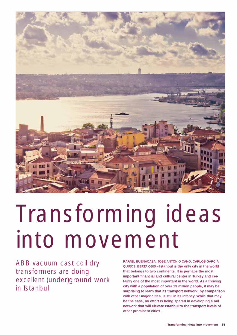
51Transforming ideas into movement
RAFAEL BUENACASA, JOSÉ ANTONIO CANO, CARLOS GARCÍA
QUIRÓS, BERTA OBIS – Istanbul is the only city in the world that belongs to two continents. It is perhaps the most important fi nancial and cultural center in Turkey and cer-tainly one of the most important in the world. As a thriving city with a population of over 13 million people, it may be surprising to learn that its transport network, by comparison with other major cities, is still in its infancy. While that may be the case, no effort is being spared in developing a rail network that will elevate Istanbul to the transport levels of other prominent cities.
ABB vacuum cast coil dry transformers are doing excellent (under)ground work in Istanbul
Transforming ideas into movement
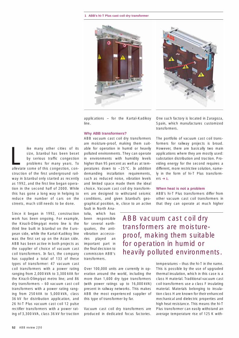
52 ABB review 2|10
One such factory is located in Zaragoza, Spain, which manufactures customized transformers.
The portfolio of vacuum cast coil trans-formers for railway projects is broad. However, there are basically two main applications where they are mostly used: substation distribution and traction. Pro-viding energy for the second requires a different, more restrictive solution, name-ly in the form of hi-T Plus transform-ers ➔ 1.
When heat is not a problem ABB’s hi-T Plus transformers differ from other vacuum cast coil transformers in that they can operate at much higher
temperatures – thus the hi-T in the name. This is possible by the use of upgraded thermal insulation, which in this case is a class H material. Traditional vacuum cast coil transformers use a class F insulating material. Materials belonging to insula-tion class H are known for their enhanced mechanical and dielectric properties and high heat resistance. This means the hi-T Plus transformer can easily withstand an average temperature rise of 125 K with-
applications – for the Kartal-Kadikoy line.
Why ABB transformers?ABB vacuum cast coil dry transformers are moisture-proof, making them suit-able for operation in humid or heavily polluted environments. They can operate in environments with humidity levels higher than 95 percent as well as at tem-peratures down to – 25 °C. In addition demanding installation requirements, such as reduced noise, vibration levels and limited space made them the ideal choice. Vacuum cast coil dry transform-ers are designed to withstand seismic conditions, and given Istanbul’s geo-graphical position, ie, close to an active fault in North Ana-tolia, which has been responsible for several earth-quakes, the anti-vibration accesso-ries played an important part in the final decision to commission ABB's transformers.
Over 100,000 units are currently in op-eration around the world, including the more than 1,600 dry type transformers (with power ratings up to 16,000 kVA) present in railway networks. This makes ABB the most experienced supplier of this type of transformer by far.
Vacuum cast coil dry transformers are produced in dedicated focus factories.
L ike many other cities of its size, Istanbul has been beset by serious traffic congestion problems for many years. To
alleviate some of this congestion, con-struction of the first underground rail-way in Istanbul only started as recently as 1992, and the first line began opera-tion in the second half of 2000. While this has gone a long way in helping to reduce the number of cars on the streets, much still needs to be done.
Since it began in 1992, construction work has been ongoing. For example, the Kirazli-Olimpiyat metro line is the third line built in Istanbul on the Euro-pean side, while the Kartal-Kadikoy line was the first set up on the Asian side. ABB has been active in both projects as the supplier of choice of vacuum cast coil transformers. In fact, the company has supplied a total of 133 of these types of transformer: 47 vacuum cast coil transformers with a power rating ranging from 2,000 kVA to 3,300 kVA for the Kirazli-Olimpiyat metro line; and 86 dry transformers – 60 vacuum cast coil transformers with a power rating rang-ing from 250 kVA to 5,000 kVA, class 36 kV for distribution application, and 26 hi-T Plus vacuum cast coil 12 pulse rectifier transformers with a power rat-ing of 3,300 kVA, class 36 kV for traction
1 ABB’s hi-T Plus cast coil dry transformer
ABB vacuum cast coil dry transformers are moisture-proof, making them suitable for operation in humid or heavily polluted environments.
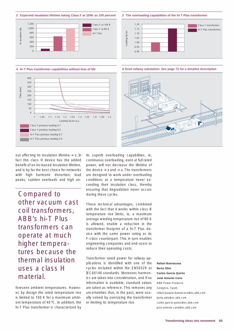
53Transforming ideas into movement
its superb overloading capabilities, ie, continuous overloading, even at full rated power, will not decrease the lifetime of the device ➔ 3 and ➔ 4. The transformers are designed to work under overloading conditions at a temperature never ex-ceeding their insulation class, thereby ensuring that degradation never occurs during these cycles.
These technical advantages, combined with the fact that it works within class B temperature rise limits, ie, a maximum average winding temperature rise of 80 K is allowed, enable a reduction in the transformer footprint of a hi-T Plus de-vice with the same power rating as its F-class counterpart. This in turn enables engineering companies and end-users to reduce their operating costs.
Transformer rated power for railway ap-plications is identified with one of the cycles included within the EN50329 or IEC60146 standards. Moreover, harmon-ics are taken into consideration, and if no information is available, standard values are taken as reference. This removes any uncertainties that, in the past, were usu-ally solved by oversizing the transformer or limiting its temperature rise.
out affecting its insulation lifetime ➔ 2. In fact this class H device has the added benefit of an increased insulation lifetime, and is by far the best choice for networks with high harmonic distortion, load peaks, sudden overloads and high un-
foreseen ambient temperatures. Howev-er, by design the rated temperature rise is limited to 100 K for a maximum ambi-ent temperature of 40 ºC. In addition, the hi-T Plus transformer is characterized by
2 Expected insulation lifetime taking Class F at 100K as 100 percent
1,200
1,000
800
600
400
200
0
% in
sula
tion
life
Class F at 100 K
Class F at 80 K
hi-T Plus
4 hi-T Plus transformer capabilities without loss of life
400
350
300
250
200
150
100
50
0
Tim
e (m
in)
Loading factor p.u.
1 1.05 1.1 1.15 1.2 1.25 1.3 1.35 1.4 1.45 1.5
Class F previous loading 0.7
Class F previous loading 0.9
hi-T Plus previous loading 0.7
hi-T Plus previous loading 0.9
Rafael Buenacasa
Berta Obis
Carlos García Quirós
José Antonio Cano
ABB Power Products
Zaragoza, Spain.
3 The overloading capabilities of the hi-T Plus transformer
1.20
1.15
1.10
1.05
1.00
0.95
0.90
Class F transformer
hi-T Plus transformer
Load
ing
fact
or
A fixed railway substation. See page 72 for a detailed description
Compared to other vacuum cast coil transformers, ABB’s hi-T Plus transformers can operate at much higher tempera-tures because the thermal insulation uses a class H material.
54 ABB review 2|10
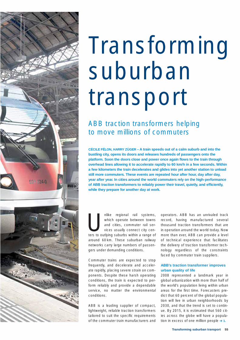
55Transforming suburban transport
CÉCILE FÉLON, HARRY ZÜGER – A train speeds out of a calm suburb and into the bustling city, opens its doors and releases hundreds of passengers onto the platform. Soon the doors close and power once again fl ows to the train through overhead lines allowing it to accelerate rapidly to 60 km/h in a few seconds. Within a few kilometers the train decelerates and glides into yet another station to unload still more commuters. These events are repeated hour after hour, day after day, year after year. In cities around the world commuters rely on the high-performance of ABB traction transformers to reliably power their travel, quietly, and effi ciently, while they prepare for another day at work.
ABB traction transformers helping to move millions of commuters
Transforming suburban transport
Unlike regional rail systems, which operate between towns and cities, commuter rail ser-vices usually connect city cen-
ters to outlying suburbs within a range of around 60 km. These suburban railway networks carry large numbers of passen-gers under demanding conditions.
Commuter trains are expected to stop frequently, and decelerate and acceler-ate rapidly, placing severe strain on com-ponents. Despite these harsh operating conditions, the train is expected to per-form reliably and provide a dependable service, no matter the environmental conditions.
ABB is a leading supplier of compact, lightweight, reliable traction transformers tailored to suit the specific requirements of the commuter train manufacturers and
operators. ABB has an unrivaled track record, having manufactured several thousand traction transformers that are in operation around the world today. Now more than ever, ABB can provide a level of technical experience that facilitates the delivery of traction transformer tech-nology regardless of the constraints faced by commuter train suppliers.
ABB’s traction transformer improves urban quality of life2008 represented a landmark year in global urbanization with more than half of the world’s population living within urban areas for the first time. Forecasters pre-dict that 60 percent of the global popula-tion will live in urban neighborhoods by 2030, and that the trend is set to contin-ue. By 2015, it is estimated that 560 cit-ies across the globe will have a popula-tion in excess of one million people ➔ 1.
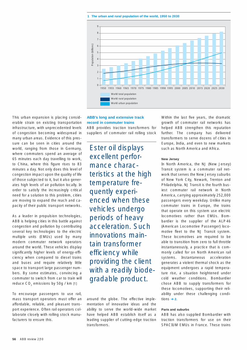
56 ABB review 2|10
Within the last five years, the dramatic growth of commuter rail networks has helped ABB strengthen this reputation further. The company has delivered transformers to serve dozens of cities in Europe, India, and even to new markets such as North America and Africa.
New Jersey
In North America, the NJ (New Jersey) Transit system is a commuter rail net-work that serves the New Jersey suburbs of New York City, Newark, Trenton and Philadelphia. NJ Transit is the fourth bus-iest commuter rail network in North America, carrying approximately 252,000 passengers every weekday. Unlike many commuter trains in Europe, the trains that operate on this system use electric locomotives rather than EMUs. Bom-bardier is the supplier of the ALP 46 (American Locomotive Passenger) loco-motive fleet to the NJ Transit system. These locomotives are required to be able to transition from zero to full throttle instantaneously, a practice that is com-monly called for on North American rail systems. Instantaneous acceleration generates a violent thermal shock as the equipment undergoes a rapid tempera-ture rise, a situation heightened under cold weather conditions. Bombardier chose ABB to supply transformers for these locomotives, supporting their reli-ability under these challenging condi-tions ➔ 2.
Paris and suburbs
ABB has also supplied Bombardier with traction transformers for use on their SPACIUM EMUs in France. These trains
ABB’s long and extensive track record in commuter trainsABB provides traction transformers for suppliers of commuter rail rolling stock
around the globe. The effective imple-mentation of innovative ideas and the ability to serve the world-wide market have helped ABB establish itself as a leading supplier of cutting-edge traction transformers.
Ester oil displays excellent perfor-mance charac-teristics at the high temperature fre-quently experi-enced when these vehicles undergo periods of heavy acceleration. Such innovations main-tain transformer effi ciency while providing the client with a readily biode-gradable product.
This urban expansion is placing consid-erable strain on existing transportation infrastructure, with unprecedented levels of congestion becoming widespread in many urban areas. Evidence of this pres-sure can be seen in cities around the world, ranging from those in Germany, where commuters spend an average of 65 minutes each day travelling to work, to China, where this figure rises to 83 minutes a day. Not only does this level of congestion impact upon the quality of life of those subjected to it, but it also gener-ates high levels of air pollution locally. In order to satisfy the increasingly critical need for a solution to this problem, cities are moving to expand the reach and ca-pacity of their public transport networks.
As a leader in propulsion technologies, ABB is helping cities in this battle against congestion and pollution by contributing several key technologies to the electric multiple units (EMUs) used by many modern commuter network operators around the world. These vehicles display significantly higher levels of energy-effi-ciency when compared to diesel trains and buses and require relatively little space to transport large passenger num-bers. By some estimates, convincing a commuter to switch from car to train will reduce CO2 emissions by 50g / km [1]
To encourage passengers to use rail, mass transport operators must offer an affordable, reliable, and pleasant trans-port experience. Often rail operators col-laborate closely with rolling stock manu-facturers to ensure this.
1 The urban and rural population of the world, 1950 to 2030
1950 1955 1960 1965 1970 1975 1980 1985 1990 1995 2000 2005 2010 2015 2020 2025 2030
Pop
ulat
ion
(bill
ions
)
9
8
7
6
5
4
3
2
1
0
World total population
World rural population
World urban population
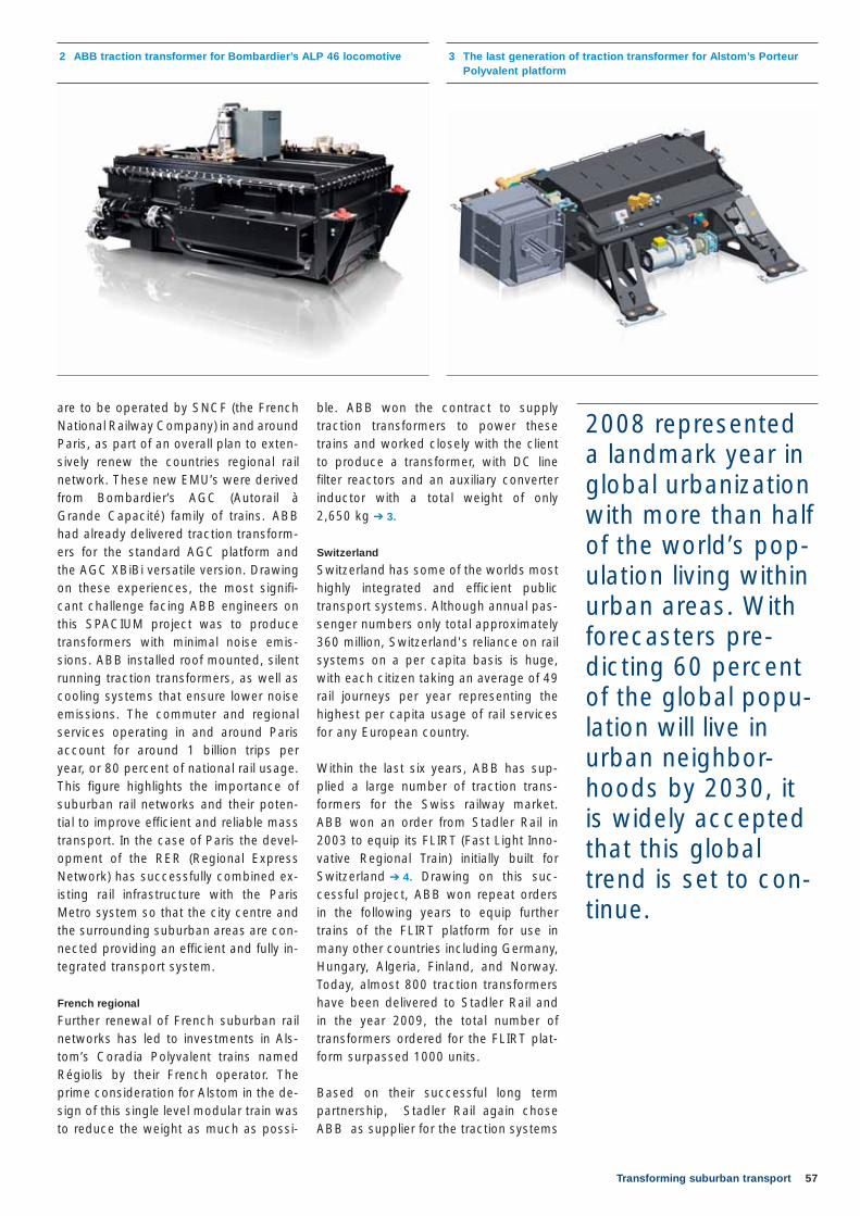
57Transforming suburban transport
ble. ABB won the contract to supply traction transformers to power these trains and worked closely with the client to produce a transformer, with DC line filter reactors and an auxiliary converter inductor with a total weight of only 2,650 kg ➔ 3.
Switzerland
Switzerland has some of the worlds most highly integrated and efficient public transport systems. Although annual pas-senger numbers only total approximately 360 million, Switzerland's reliance on rail systems on a per capita basis is huge, with each citizen taking an average of 49 rail journeys per year representing the highest per capita usage of rail services for any European country.
Within the last six years, ABB has sup-plied a large number of traction trans-formers for the Swiss railway market. ABB won an order from Stadler Rail in 2003 to equip its FLIRT (Fast Light Inno-vative Regional Train) initially built for Switzerland ➔ 4. Drawing on this suc-cessful project, ABB won repeat orders in the following years to equip further trains of the FLIRT platform for use in many other countries including Germany, Hungary, Algeria, Finland, and Norway. Today, almost 800 traction transformers have been delivered to Stadler Rail and in the year 2009, the total number of transformers ordered for the FLIRT plat-form surpassed 1000 units.
Based on their successful long term partnership, Stadler Rail again chose ABB as supplier for the traction systems
are to be operated by SNCF (the French National Railway Company) in and around Paris, as part of an overall plan to exten-sively renew the countries regional rail network. These new EMU’s were derived from Bombardier’s AGC (Autorail à Grande Capacité) family of trains. ABB had already delivered traction transform-ers for the standard AGC platform and the AGC XBiBi versatile version. Drawing on these experiences, the most signifi-cant challenge facing ABB engineers on this SPACIUM project was to produce transformers with minimal noise emis-sions. ABB installed roof mounted, silent running traction transformers, as well as cooling systems that ensure lower noise emissions. The commuter and regional services operating in and around Paris account for around 1 billion trips per year, or 80 percent of national rail usage. This figure highlights the importance of suburban rail networks and their poten-tial to improve efficient and reliable mass transport. In the case of Paris the devel-opment of the RER (Regional Express Network) has successfully combined ex-isting rail infrastructure with the Paris Metro system so that the city centre and the surrounding suburban areas are con-nected providing an efficient and fully in-tegrated transport system.
French regional
Further renewal of French suburban rail networks has led to investments in Als-tom’s Coradia Polyvalent trains named Régiolis by their French operator. The prime consideration for Alstom in the de-sign of this single level modular train was to reduce the weight as much as possi-
2 ABB traction transformer for Bombardier’s ALP 46 locomotive 3 The last generation of traction transformer for Alstom’s Porteur Polyvalent platform
2008 represented a landmark year in global urbanization with more than half of the world’s pop-ulation living within urban areas. With forecasters pre-dicting 60 percent of the global popu-lation will live in urban neighbor-hoods by 2030, it is widely accepted that this global trend is set to con-tinue.
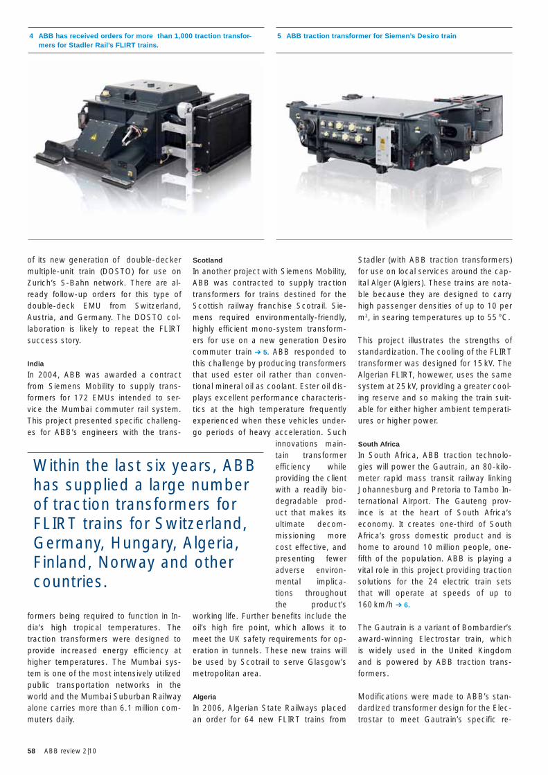
58 ABB review 2|10
Stadler (with ABB traction transformers) for use on local services around the cap-ital Alger (Algiers). These trains are nota-ble because they are designed to carry high passenger densities of up to 10 per m2, in searing temperatures up to 55 °C.
This project illustrates the strengths of standardization. The cooling of the FLIRT transformer was designed for 15 kV. The Algerian FLIRT, howewer, uses the same system at 25 kV, providing a greater cool-ing reserve and so making the train suit-able for either higher ambient temperati-ures or higher power.
South Africa
In South Africa, ABB traction technolo-gies will power the Gautrain, an 80-kilo-meter rapid mass transit railway linking Johannesburg and Pretoria to Tambo In-ternational Airport. The Gauteng prov-ince is at the heart of South Africa’s economy. It creates one-third of South Africa’s gross domestic product and is home to around 10 million people, one-fifth of the population. ABB is playing a vital role in this project providing traction solutions for the 24 electric train sets that will operate at speeds of up to 160 km/h ➔ 6.
The Gautrain is a variant of Bombardier’s award-winning Electrostar train, which is widely used in the United Kingdom and is powered by ABB traction trans-formers.
Modifications were made to ABB’s stan-dardized transformer design for the Elec-trostar to meet Gautrain’s specific re-
Scotland
In another project with Siemens Mobility, ABB was contracted to supply traction transformers for trains destined for the Scottish railway franchise Scotrail. Sie-mens required environmentally-friendly, highly efficient mono-system transform-ers for use on a new generation Desiro commuter train ➔ 5. ABB responded to this challenge by producing transformers that used ester oil rather than conven-tional mineral oil as coolant. Ester oil dis-plays excellent performance characteris-tics at the high temperature frequently experienced when these vehicles under-go periods of heavy acceleration. Such
innovations main-tain transformer efficiency while providing the client with a readily bio-degradable prod-uct that makes its ultimate decom-missioning more cost effective, and presenting fewer adverse environ-mental implica-tions throughout the product’s
working life. Further benefits include the oil’s high fire point, which allows it to meet the UK safety requirements for op-eration in tunnels. These new trains will be used by Scotrail to serve Glasgow’s metropolitan area.
Algeria
In 2006, Algerian State Railways placed an order for 64 new FLIRT trains from
of its new generation of double-decker multiple-unit train (DOSTO) for use on Zurich’s S-Bahn network. There are al-ready follow-up orders for this type of double-deck EMU from Switzerland, Austria, and Germany. The DOSTO col-laboration is likely to repeat the FLIRT success story.
India
In 2004, ABB was awarded a contract from Siemens Mobility to supply trans-formers for 172 EMUs intended to ser-vice the Mumbai commuter rail system. This project presented specific challeng-es for ABB’s engineers with the trans-
formers being required to function in In-dia’s high tropical temperatures. The traction transformers were designed to provide increased energy efficiency at higher temperatures. The Mumbai sys-tem is one of the most intensively utilized public transportation networks in the world and the Mumbai Suburban Railway alone carries more than 6.1 million com-muters daily.
5 ABB traction transformer for Siemen’s Desiro train
Within the last six years, ABB has supplied a large number of traction transformers for FLIRT trains for Switzerland, Germany, Hungary, Algeria, Finland, Norway and other countries.
4 ABB has received orders for more than 1,000 traction transfor-mers for Stadler Rail’s FLIRT trains.
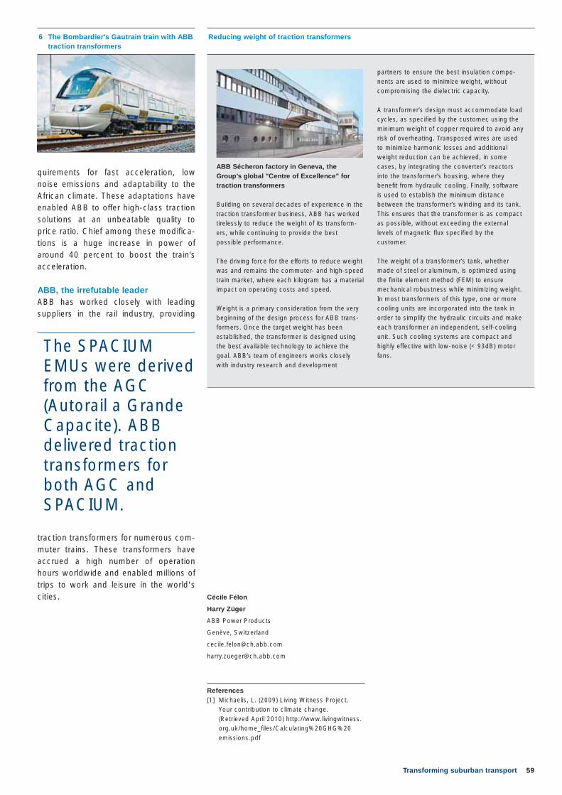
59Transforming suburban transport
Cécile Félon
Harry Züger
ABB Power Products
Genève, Switzerland
References[1] Michaelis, L. (2009) Living Witness Project.
Your contribution to climate change. (Retrieved April 2010) http://www.livingwitness.org.uk/home_files/Calculating%20GHG%20emissions.pdf
quirements for fast acceleration, low noise emissions and adaptability to the African climate. These adaptations have enabled ABB to offer high-class traction solutions at an unbeatable quality to price ratio. Chief among these modifica-tions is a huge increase in power of around 40 percent to boost the train’s acceleration.
ABB, the irrefutable leaderABB has worked closely with leading suppliers in the rail industry, providing
traction transformers for numerous com-muter trains. These transformers have accrued a high number of operation hours worldwide and enabled millions of trips to work and leisure in the world's cities.
Reducing weight of traction transformers
Building on several decades of experience in the traction transformer business, ABB has worked tirelessly to reduce the weight of its transform-ers, while continuing to provide the best possible performance.
The driving force for the efforts to reduce weight was and remains the commuter- and high-speed train market, where each kilogram has a material impact on operating costs and speed.
Weight is a primary consideration from the very beginning of the design process for ABB trans -formers. Once the target weight has been established, the transformer is designed using the best available technology to achieve the goal. ABB’s team of engineers works closely with industry research and development
partners to ensure the best insulation compo-nents are used to minimize weight, without compromising the dielectric capacity.
A transformer’s design must accommodate load cycles, as specified by the customer, using the minimum weight of copper required to avoid any risk of overheating. Transposed wires are used to minimize harmonic losses and additional weight reduction can be achieved, in some cases, by integrating the converter’s reactors into the transformer’s housing, where they benefit from hydraulic cooling. Finally, software is used to establish the minimum distance between the transformer’s winding and its tank. This ensures that the transformer is as compact as possible, without exceeding the external levels of magnetic flux specified by the customer.
The weight of a transformer’s tank, whether made of steel or aluminum, is optimized using the finite element method (FEM) to ensure mechanical robustness while minimizing weight. In most transformers of this type, one or more cooling units are incorporated into the tank in order to simplify the hydraulic circuits and make each transformer an independent, self-cooling unit. Such cooling systems are compact and highly effective with low-noise (< 93dB) motor fans.
6 The Bombardier’s Gautrain train with ABB traction transformers
The SPACIUM EMUs were derived from the AGC (Autorail a Grande Capacite). ABB delivered traction transformers for both AGC and SPACIUM.
ABB Sécheron factory in Geneva, the Group’s global "Centre of Excellence" for traction transformers
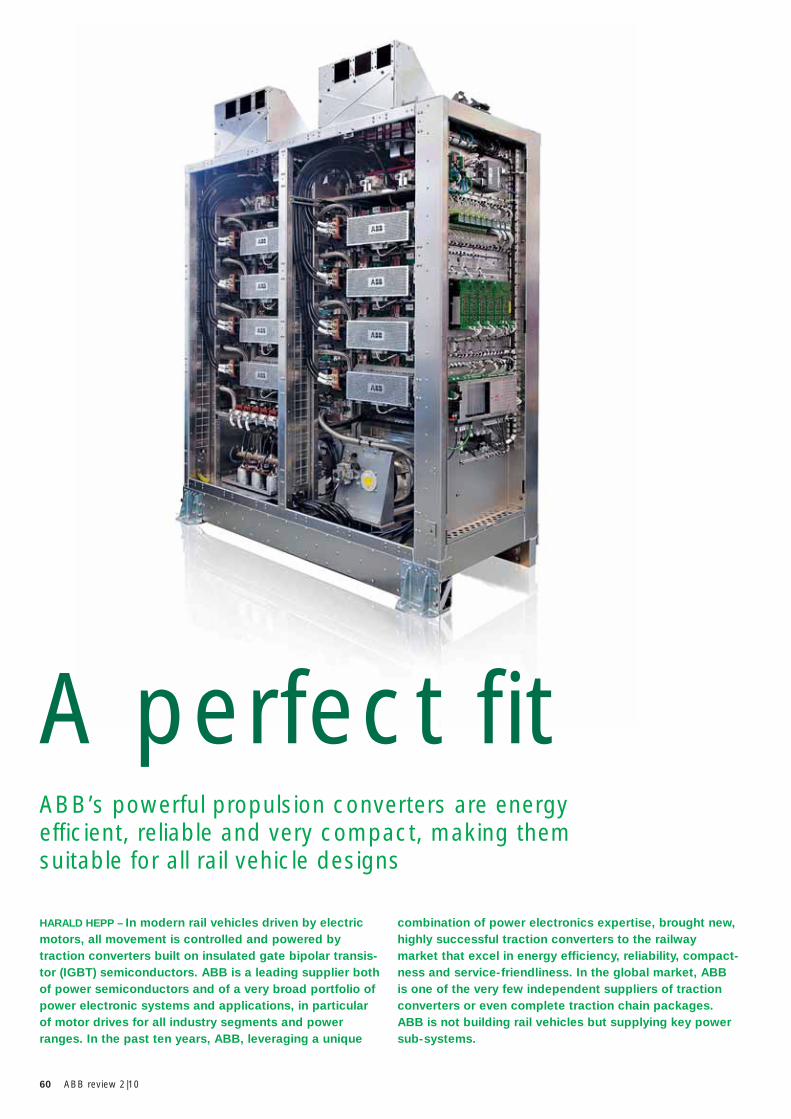
60 ABB review 2|10
HARALD HEPP – In modern rail vehicles driven by electric motors, all movement is controlled and powered by traction converters built on insulated gate bipolar transis-tor (IGBT) semiconductors. ABB is a leading supplier both of power semiconductors and of a very broad portfolio of power electronic systems and applications, in particular of motor drives for all industry segments and power ranges. In the past ten years, ABB, leveraging a unique
combination of power electronics expertise, brought new, highly successful traction converters to the railway market that excel in energy efficiency, reliability, compact-ness and service-friendliness. In the global market, ABB is one of the very few independent suppliers of traction converters or even complete traction chain packages. ABB is not building rail vehicles but supplying key power sub-systems.
ABB’s powerful propulsion converters are energy efficient, reliable and very compact, making them suitable for all rail vehicle designs
A perfect fit
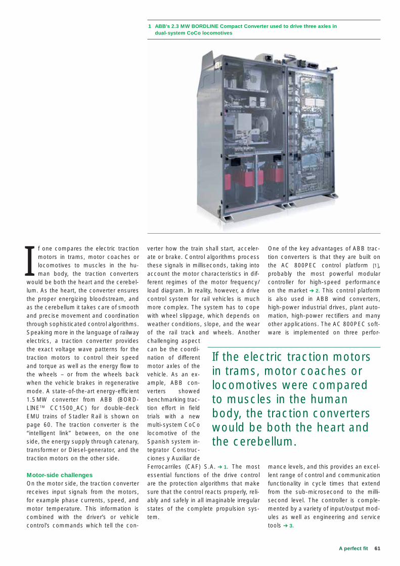
61A perfect fit
One of the key advantages of ABB trac-tion converters is that they are built on the AC 800PEC control platform [1], probably the most powerful modular controller for high-speed performance on the market ➔ 2. This control platform is also used in ABB wind converters, high-power industrial drives, plant auto-mation, high-power rectifiers and many other applications. The AC 800PEC soft-ware is implemented on three perfor-
mance levels, and this provides an excel-lent range of control and communication functionality in cycle times that extend from the sub-microsecond to the milli-second level. The controller is comple-mented by a variety of input/output mod-ules as well as engineering and service tools ➔ 3.
verter how the train shall start, acceler-ate or brake. Control algorithms process these signals in milliseconds, taking into account the motor characteristics in dif-ferent regimes of the motor frequency/load diagram. In reality, however, a drive control system for rail vehicles is much more complex. The system has to cope with wheel slippage, which depends on weather conditions, slope, and the wear of the rail track and wheels. Another challenging aspect can be the coordi-nation of different motor axles of the vehicle. As an ex-ample, ABB con-verters showed benchmarking trac-tion effort in field trials with a new multi-system CoCo locomotive of the Spanish system in-tegrator Construc-ciones y Auxiliar de Ferrocarriles (CAF) S.A. ➔ 1. The most essential functions of the drive control are the protection algorithms that make sure that the control reacts properly, reli-ably and safely in all imaginable irregular states of the complete propulsion sys-tem.
I f one compares the electric traction motors in trams, motor coaches or locomotives to muscles in the hu-man body, the traction converters
would be both the heart and the cerebel-lum. As the heart, the converter ensures the proper energizing bloodstream, and as the cerebellum it takes care of smooth and precise movement and coordination through sophisticated control algorithms. Speaking more in the language of railway electrics, a traction converter provides the exact voltage wave patterns for the traction motors to control their speed and torque as well as the energy flow to the wheels – or from the wheels back when the vehicle brakes in regenerative mode. A state-of-the-art energy-efficient 1.5 MW converter from ABB (BORD-LINETM CC1500_AC) for double-deck EMU trains of Stadler Rail is shown on page 60. The traction converter is the “intelligent link” between, on the one side, the energy supply through catenary, transformer or Diesel-generator, and the traction motors on the other side.
Motor-side challengesOn the motor side, the traction converter receives input signals from the motors, for example phase currents, speed, and motor temperature. This information is combined with the driver’s or vehicle control’s commands which tell the con-
1 ABB’s 2.3 MW BORDLINE Compact Converter used to drive three axles in dual-system CoCo locomotives
If the electric traction motors in trams, motor coaches or locomotives were compared to muscles in the human body, the traction converters would be both the heart and the cerebellum.
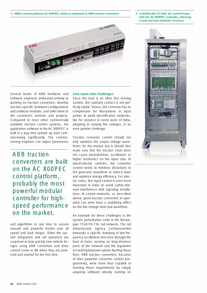
62 ABB review 2|10
Line-input-side challengesSince the train is an often fast moving system, the catenary contact is not per-fectly stable. Hence, the converter has to compensate for fluctuations in input power. In weak electrification networks, like for instance in some parts of India, adapting to varying line voltages, is an even greater challenge. Traction converter control should not only optimize the output voltage wave-forms for the motors but it should also make sure that the traction chain does not cause perturbations, oscillations or higher harmonics on the input side. In diesel-electric vehicles, the converter control needs to minimize distortions in the generator waveform to reduce wear and optimize energy efficiency. For elec-tric trains, line-input control is even more important in order to avoid safety-rele-vant interference with signaling installa-tions. In certain networks, as described above, good traction converters in oper-ation can even have a stabilizing effect on the line voltage level and waveform.
An example for these challenges is the system perturbation code in the Norwe-gian 15 kV/16.7 Hz rail network. The rail infrastructure agency Jernbaneverket demands a specific damping of low-fre-quency oscillations that arise through the load of trains running on long-distance parts of the network and the regulation of small hydropower plants feeding these lines. ABB traction converters, because of their powerful converter control pro-gramming, were more than capable of meeting these requirements by simply adapting software already running on
Several teams of ABB hardware and software engineers dedicated entirely to working on traction converters, develop traction-specific hardware configurations and software modules, and tailor them to the customer’s vehicles and projects. Compared to most other commercially available traction control systems, the application software in the AC 800PEC is built in a way that speeds up train com-missioning significantly. The commis-sioning engineer can adjust parameters
and algorithms in real time to ensure smooth and powerful motion over all speed and load ranges. Often the sys-tem integrators and rail operators are surprised at how quickly new vehicle de-signs using ABB converters and drive control come to life when they are pow-ered and started for the first time.
2 ABB’s control platform AC 800PEC, which is employed in ABB traction converters 3 A BORDLINE CC1500_AC control frame with the AC 800PEC controller, reflecting a neat and lean hardware structure
ABB traction converters are built on the AC 800PEC control platform, probably the most powerful modular controller for high-speed performance on the market.
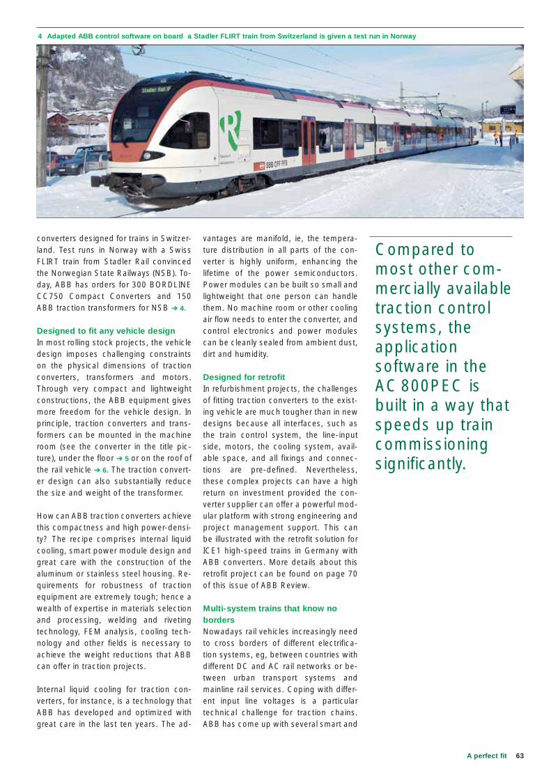
63A perfect fit
4 Adapted ABB control software on board a Stadler FLIRT train from Switzerland is given a test run in Norway
vantages are manifold, ie, the tempera-ture distribution in all parts of the con-verter is highly uniform, enhancing the lifetime of the power semiconductors. Power modules can be built so small and lightweight that one person can handle them. No machine room or other cooling air flow needs to enter the converter, and control electronics and power modules can be cleanly sealed from ambient dust, dirt and humidity.
Designed for retrofitIn refurbishment projects, the challenges of fitting traction converters to the exist-ing vehicle are much tougher than in new designs because all interfaces, such as the train control system, the line-input side, motors, the cooling system, avail-able space, and all fixings and connec-tions are pre-defined. Nevertheless, these complex projects can have a high return on investment provided the con-verter supplier can offer a powerful mod-ular platform with strong engineering and project management support. This can be illustrated with the retrofit solution for ICE1 high-speed trains in Germany with ABB converters. More details about this retrofit project can be found on page 70 of this issue of ABB Review.
Multi-system trains that know no bordersNowadays rail vehicles increasingly need to cross borders of different electrifica-tion systems, eg, between countries with different DC and AC rail networks or be-tween urban transport systems and mainline rail services. Coping with differ-ent input line voltages is a particular technical challenge for traction chains. ABB has come up with several smart and
converters designed for trains in Switzer-land. Test runs in Norway with a Swiss FLIRT train from Stadler Rail convinced the Norwegian State Railways (NSB). To-day, ABB has orders for 300 BORDLINE CC750 Compact Converters and 150 ABB traction transformers for NSB ➔ 4.
Designed to fit any vehicle designIn most rolling stock projects, the vehicle design imposes challenging constraints on the physical dimensions of traction converters, transformers and motors. Through very compact and lightweight constructions, the ABB equipment gives more freedom for the vehicle design. In principle, traction converters and trans-formers can be mounted in the machine room (see the converter in the title pic-ture), under the floor ➔ 5 or on the roof of the rail vehicle ➔ 6. The traction convert-er design can also substantially reduce the size and weight of the transformer.
How can ABB traction converters achieve this compactness and high power-densi-ty? The recipe comprises internal liquid cooling, smart power module design and great care with the construction of the aluminum or stainless steel housing. Re-quirements for robustness of traction equipment are extremely tough; hence a wealth of expertise in materials selection and processing, welding and riveting technology, FEM analysis, cooling tech-nology and other fields is necessary to achieve the weight reductions that ABB can offer in traction projects.
Internal liquid cooling for traction con-verters, for instance, is a technology that ABB has developed and optimized with great care in the last ten years. The ad-
Compared to most other com-mercially available traction control systems, the application software in the AC 800PEC is built in a way that speeds up train commissioning significantly.
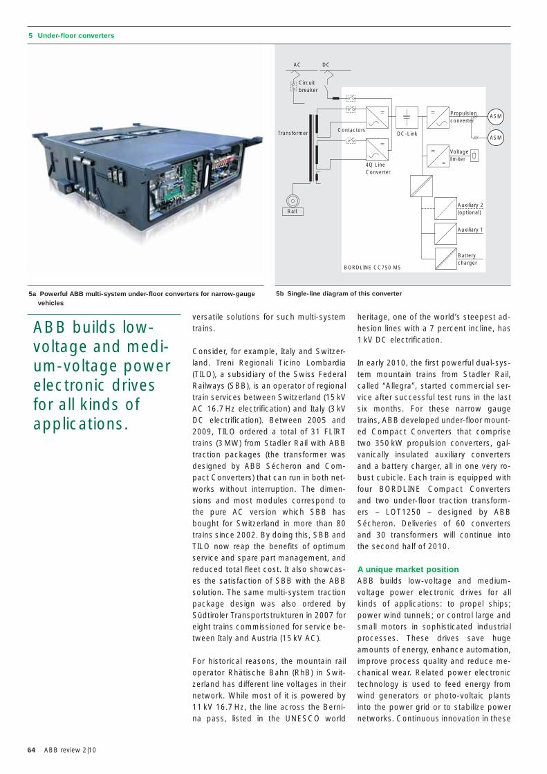
64 ABB review 2|10
versatile solutions for such multi-system trains.
Consider, for example, Italy and Switzer-land. Treni Regionali Ticino Lombardia (TILO), a subsidiary of the Swiss Federal Railways (SBB), is an operator of regional train services between Switzerland (15 kV AC 16.7 Hz electrification) and Italy (3 kV DC electrification). Between 2005 and 2009, TILO ordered a total of 31 FLIRT trains (3 MW) from Stadler Rail with ABB traction packages (the transformer was designed by ABB Sécheron and Com-pact Converters) that can run in both net-works without interruption. The dimen-sions and most modules correspond to the pure AC version which SBB has bought for Switzerland in more than 80 trains since 2002. By doing this, SBB and TILO now reap the benefits of optimum service and spare part management, and reduced total fleet cost. It also showcas-es the satisfaction of SBB with the ABB solution. The same multi-system traction package design was also ordered by Südtiroler Transportstrukturen in 2007 for eight trains commissioned for service be-tween Italy and Austria (15 kV AC).
For historical reasons, the mountain rail operator Rhätische Bahn (RhB) in Swit-zerland has different line voltages in their network. While most of it is powered by 11 kV 16.7 Hz, the line across the Berni-na pass, listed in the UNESCO world
ABB builds low-voltage and medi-um-voltage power electronic drives for all kinds of applications.
heritage, one of the world’s steepest ad-hesion lines with a 7 percent incline, has 1 kV DC electrification.
In early 2010, the first powerful dual-sys-tem mountain trains from Stadler Rail, called “Allegra”, started commercial ser-vice after successful test runs in the last six months. For these narrow gauge trains, ABB developed under-floor mount-ed Compact Converters that comprise two 350 kW propulsion converters, gal-vanically insulated auxiliary converters and a battery charger, all in one very ro-bust cubicle. Each train is equipped with four BORDLINE Compact Converters and two under-floor traction transform-ers – LOT1250 – designed by ABB Sécheron. Deliveries of 60 converters and 30 transformers will continue into the second half of 2010.
A unique market positionABB builds low-voltage and medium-voltage power electronic drives for all kinds of applications: to propel ships; power wind tunnels; or control large and small motors in sophisticated industrial processes. These drives save huge amounts of energy, enhance automation, improve process quality and reduce me-chanical wear. Related power electronic technology is used to feed energy from wind generators or photo-voltaic plants into the power grid or to stabilize power networks. Continuous innovation in these
5 Under-floor converters
5a Powerful ABB multi-system under-floor converters for narrow-gauge vehicles
5b Single-line diagram of this converter
Circuit breaker
Transformer
BORDLINE CC750 MS
4Q LineConverter
Propulsionconverter
Voltagelimiter
Auxiliary 2(optional)
Batterycharger
Auxiliary 1
ASM
ASMContactors
DC-Link
AC DC
Rail
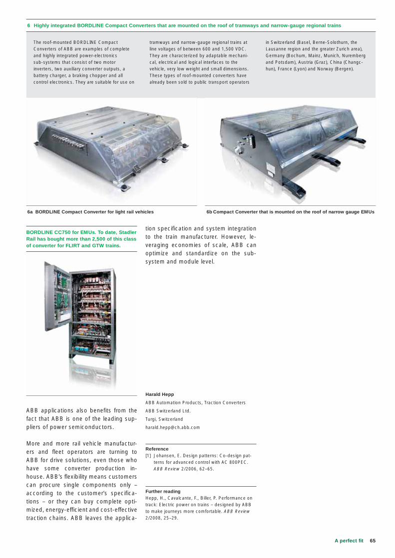
65A perfect fit
6 Highly integrated BORDLINE Compact Converters that are mounted on the roof of tramways and narrow-gauge regional trains
6a BORDLINE Compact Converter for light rail vehicles 6b Compact Converter that is mounted on the roof of narrow gauge EMUs
The roof-mounted BORDLINE Compact Converters of ABB are examples of complete and highly integrated power-electronics sub-systems that consist of two motor inverters, two auxiliary converter outputs, a battery charger, a braking chopper and all control electronics. They are suitable for use on
tramways and narrow-gauge regional trains at line voltages of between 600 and 1,500 VDC. They are characterized by adaptable mechani-cal, electrical and logical interfaces to the vehicle, very low weight and small dimensions. These types of roof-mounted converters have already been sold to public transport operators
in Switzerland (Basel, Berne-Solothurn, the Lausanne region and the greater Zurich area), Germany (Bochum, Mainz, Munich, Nuremberg and Potsdam), Austria (Graz), China (Changc-hun), France (Lyon) and Norway (Bergen).
ABB applications also benefits from the fact that ABB is one of the leading sup-pliers of power semiconductors.
More and more rail vehicle manufactur-ers and fleet operators are turning to ABB for drive solutions, even those who have some converter production in-house. ABB’s flexibility means customers can procure single components only – according to the customer’s specifica-tions – or they can buy complete opti-mized, energy-efficient and cost-effective traction chains. ABB leaves the applica-
tion specification and system integration to the train manufacturer. However, le-veraging economies of scale, ABB can optimize and standardize on the sub-system and module level.
Harald Hepp
ABB Automation Products, Traction Converters
ABB Switzerland Ltd.
Turgi, Switzerland
Reference[1] Johansen, E. Design patterns: Co-design pat-
terns for advanced control with AC 800PEC. ABB Review 2/2006, 62–65.
Further readingHepp, H., Cavalcante, F., Biller, P. Performance on track: Electric power on trains – designed by ABB to make journeys more comfortable. ABB Review 2/2008, 25–29.
BORDLINE CC750 for EMUs. To date, Stadler Rail has bought more than 2,500 of this class of converter for FLIRT and GTW trains.
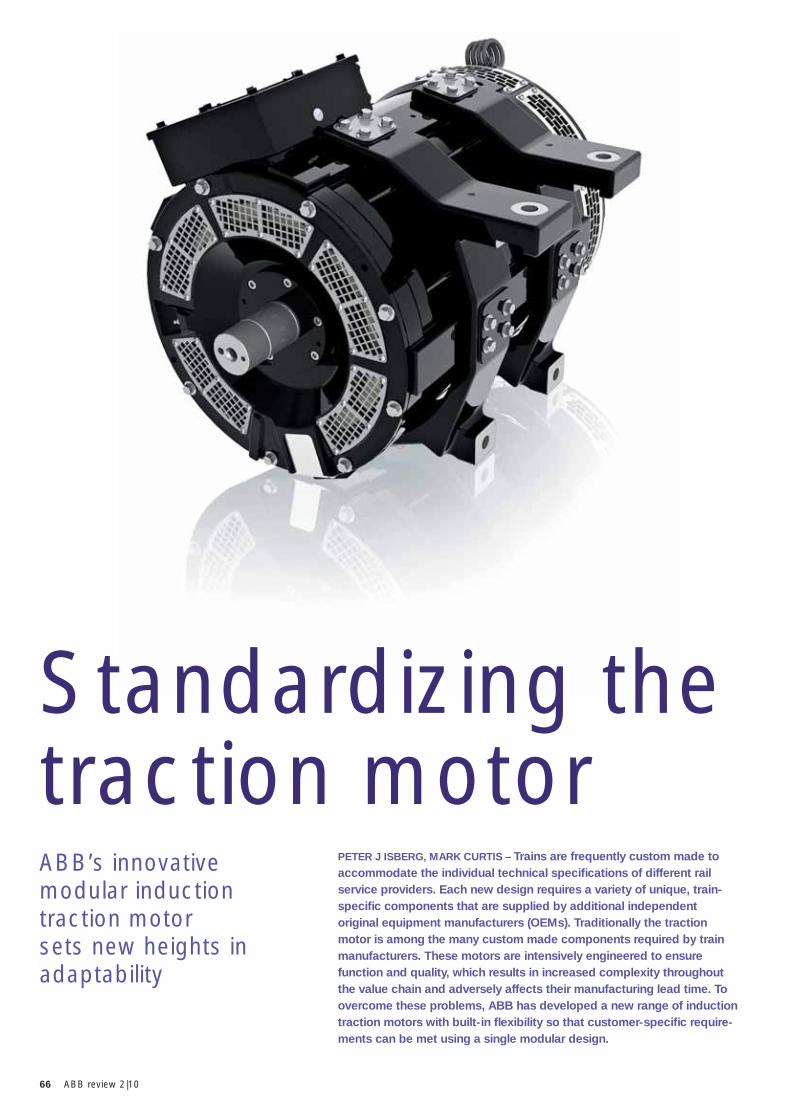
66 ABB review 2|10
PETER J ISBERG, MARK CURTIS – Trains are frequently custom made to accommodate the individual technical specifi cations of different rail service providers. Each new design requires a variety of unique, train-specifi c components that are supplied by additional independent original equipment manufacturers (OEMs). Traditionally the traction motor is among the many custom made components required by train manufacturers. These motors are intensively engineered to ensure function and quality, which results in increased complexity throughout the value chain and adversely affects their manufacturing lead time. To overcome these problems, ABB has developed a new range of induction traction motors with built-in fl exibility so that customer-specifi c require-ments can be met using a single modular design.
ABB’s innovative modular induction traction motor sets new heights in adaptability
Standardizing the traction motor
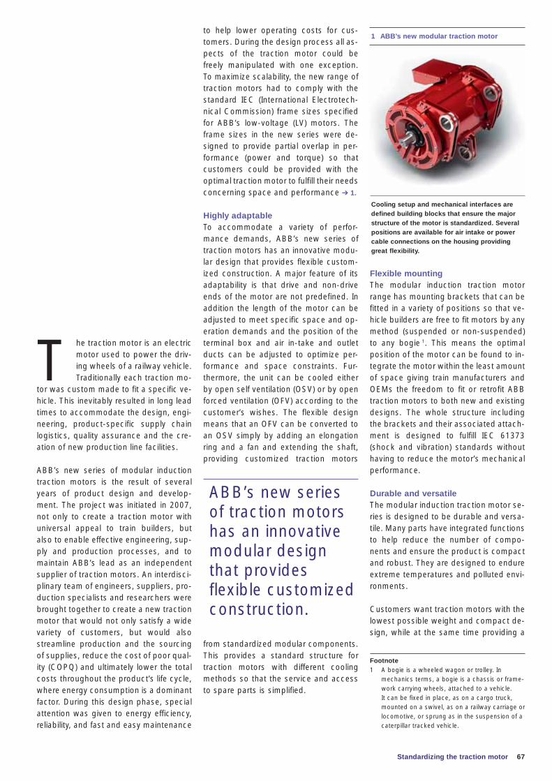
67
T he traction motor is an electric motor used to power the driv-ing wheels of a railway vehicle. Traditionally each traction mo-
tor was custom made to fit a specific ve-hicle. This inevitably resulted in long lead times to accommodate the design, engi-neering, product-specific supply chain logistics, quality assurance and the cre-ation of new production line facilities.
ABB’s new series of modular induction traction motors is the result of several years of product design and develop-ment. The project was initiated in 2007, not only to create a traction motor with universal appeal to train builders, but also to enable effective engineering, sup-ply and production processes, and to maintain ABB’s lead as an independent supplier of traction motors. An interdisci-plinary team of engineers, suppliers, pro-duction specialists and researchers were brought together to create a new traction motor that would not only satisfy a wide variety of customers, but would also streamline production and the sourcing of supplies, reduce the cost of poor qual-ity (COPQ) and ultimately lower the total costs throughout the product’s life cycle, where energy consumption is a dominant factor. During this design phase, special attention was given to energy efficiency, reliability, and fast and easy maintenance
Standardizing the traction motor
Flexible mountingThe modular induction traction motor range has mounting brackets that can be fitted in a variety of positions so that ve-hicle builders are free to fit motors by any method (suspended or non-suspended) to any bogie 1. This means the optimal position of the motor can be found to in-tegrate the motor within the least amount of space giving train manufacturers and OEMs the freedom to fit or retrofit ABB traction motors to both new and existing designs. The whole structure including the brackets and their associated attach-ment is designed to fulfill IEC 61373 (shock and vibration) standards without having to reduce the motor’s mechanical performance.
Durable and versatileThe modular induction traction motor se-ries is designed to be durable and versa-tile. Many parts have integrated functions to help reduce the number of compo-nents and ensure the product is compact and robust. They are designed to endure extreme temperatures and polluted envi-ronments.
Customers want traction motors with the lowest possible weight and compact de-sign, while at the same time providing a
to help lower operating costs for cus-tomers. During the design process all as-pects of the traction motor could be freely manipulated with one exception. To maximize scalability, the new range of traction motors had to comply with the standard IEC (International Electrotech-nical Commission) frame sizes specified for ABB’s low-voltage (LV) motors. The frame sizes in the new series were de-signed to provide partial overlap in per-formance (power and torque) so that customers could be provided with the optimal traction motor to fulfill their needs concerning space and performance ➔ 1.
Highly adaptableTo accommodate a variety of perfor-mance demands, ABB’s new series of traction motors has an innovative modu-lar design that provides flexible custom-ized construction. A major feature of its adaptability is that drive and non-drive ends of the motor are not predefined. In addition the length of the motor can be adjusted to meet specific space and op-eration demands and the position of the terminal box and air in-take and outlet ducts can be adjusted to optimize per-formance and space constraints. Fur-thermore, the unit can be cooled either by open self ventilation (OSV) or by open forced ventilation (OFV) according to the customer’s wishes. The flexible design means that an OFV can be converted to an OSV simply by adding an elongation ring and a fan and extending the shaft, providing customized traction motors
from standardized modular components. This provides a standard structure for traction motors with different cooling methods so that the service and access to spare parts is simplified.
1 ABB’s new modular traction motor
Cooling setup and mechanical interfaces are defined building blocks that ensure the major structure of the motor is standardized. Several positions are available for air intake or power cable connections on the housing providing great flexibility.
Footnote1 A bogie is a wheeled wagon or trolley. In
mechanics terms, a bogie is a chassis or frame-work carrying wheels, attached to a vehicle. It can be fixed in place, as on a cargo truck, mounted on a swivel, as on a railway carriage or locomotive, or sprung as in the suspension of a caterpillar tracked vehicle.
ABB’s new series of traction motors has an innovative modular design that provides flexible customized construction.
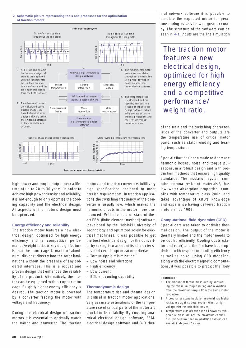
68 ABB review 2|10
mal network software it is possible to simulate the expected motor tempera-ture during its service with great accura-cy. The structure of the software can be seen in ➔ 2. Inputs are the line simulation
of the train and the switching character-istics of the converter and outputs are the temperature rise of critical motor parts, such as stator winding and bear-ing temperature.
Special effort has been made to decrease harmonic losses, noise and torque pul-sations, in a robust design and with pro-duction methods that ensure high quality standards. The insulation system con-tains corona resistant materials 3, has low water absorption properties, com-plies with temperature class 200 4, and takes advantage of ABB’s knowledge and experience having delivered traction motors since 1909.
Computational fluid dynamics (CFD)Special care was taken to optimize ther-mal design. The output of the motor is thermally limited and the motor needs to be cooled efficiently. Cooling ducts (sta-tor and rotor) and the fan have been op-timized with respect to cooling efficiency as well as noise. Using CFD modeling, along with the electromagnetic computa-tions, it was possible to predict the likely
motors and traction converters fulfill very high specifications designed to meet precise requirements. In traction applica-tions the switching frequency of the con-verter is usually low, which makes the harmonic effects in the motor more pro-nounced. With the help of state-of-the-art FEM (finite element method) software (developed by the Helsinki University of Technology and optimized solely for elec-trical machines), it was possible to get the best electrical design for the convert-er by taking into account its characteris-tics and certain optimization criteria: – Torque ripple minimization 2
– Low noise and vibrations– High efficiency– Low current– Efficient cooling capability
Thermodynamic designThe temperature rise and thermal design is critical in traction motor applications. Very accurate estimations of the temper-ature rise of critical parts of the motor are crucial to its reliability. By coupling ana-lytical electrical design software, FEM-electrical design software and 3-D ther-
high power and torque output over a life-time of up to 20 to 30 years. In order to achieve high power density and reliability, it is not enough to only optimize the cool-ing capability and the electrical design. All aspects of the motor’s design must be optimized.
Energy efficiency and reliability The traction motor features a new elec-trical design, optimized for high energy efficiency and a competitive perfor-mance/weight ratio. A key design feature is that the rotor cage is made of alumi-num, die-cast directly into the rotor lami-nations without the presence of any sol-dered interfaces. This is a robust and proven design that enhances the reliabil-ity of the product. Alternatively, the mo-tor can be equipped with a copper rotor cage if slightly higher energy efficiency is desired. The traction motor is powered by a converter feeding the motor with voltage and frequency.
During the electrical design of traction motors it is essential to optimally match the motor and converter. The traction
The traction motor features a new electrical design, optimized for high energy efficiency and a competitive performance/weight ratio.
Footnotes2 The amount of torque measured by subtract-
ing the minimum torque during one revolution from the maximum torque from the same motor revolution.
3 A corona resistant insulation material has higher resistance against deterioration when a high-voltage electrostatic field ionizes.
4 Temperature classification (also known as tem-perature class) defines the maximum continu-ous temperature that an insulation system can sustain in degrees Celsius.
2 Schematic picture representing tools and processes for the optimization of traction motors
Analytical electromagneticdesign software
Finite elementelectromagnetic design
software
Strong interaction
Weak interaction
Train operation cycle
Traction converter characteristics
Train effort versus time throughout the line profile
Phase to phase motor voltage versus time Stator winding temerature rise versus time
1. The fundamental motor losses are calculated throughout the train line using ABB developed analytical electrical motor design software.
4. The temperature rise is calculated and the resulting temperature is used as input to the design software, which will generate accurate thermal predictions and thus ensure reliable motor operation.
3. A 3-D lumped parame-ter thermal design soft-ware is then updated with the fundamental losses from the ana-lytical software and the time harmonic losses from the FEM software.
2. Time harmonic losses are calculated using custom made FEM-based electrical motor design software taking the switching strategy of the converter into account.
Trai
n sp
eed
Train speed versus time throughout the line profile
Trai
n ef
fort
Mot
or v
olta
ge
Sta
tor
win
din
gte
mp
erat
ure
rise
(K)
Time
Time TimeUab
Time
Motortemperatures
Sinusoidal losses
Motortemperatures
3-D lumped parameterthermal design software
Time harmoniclosses
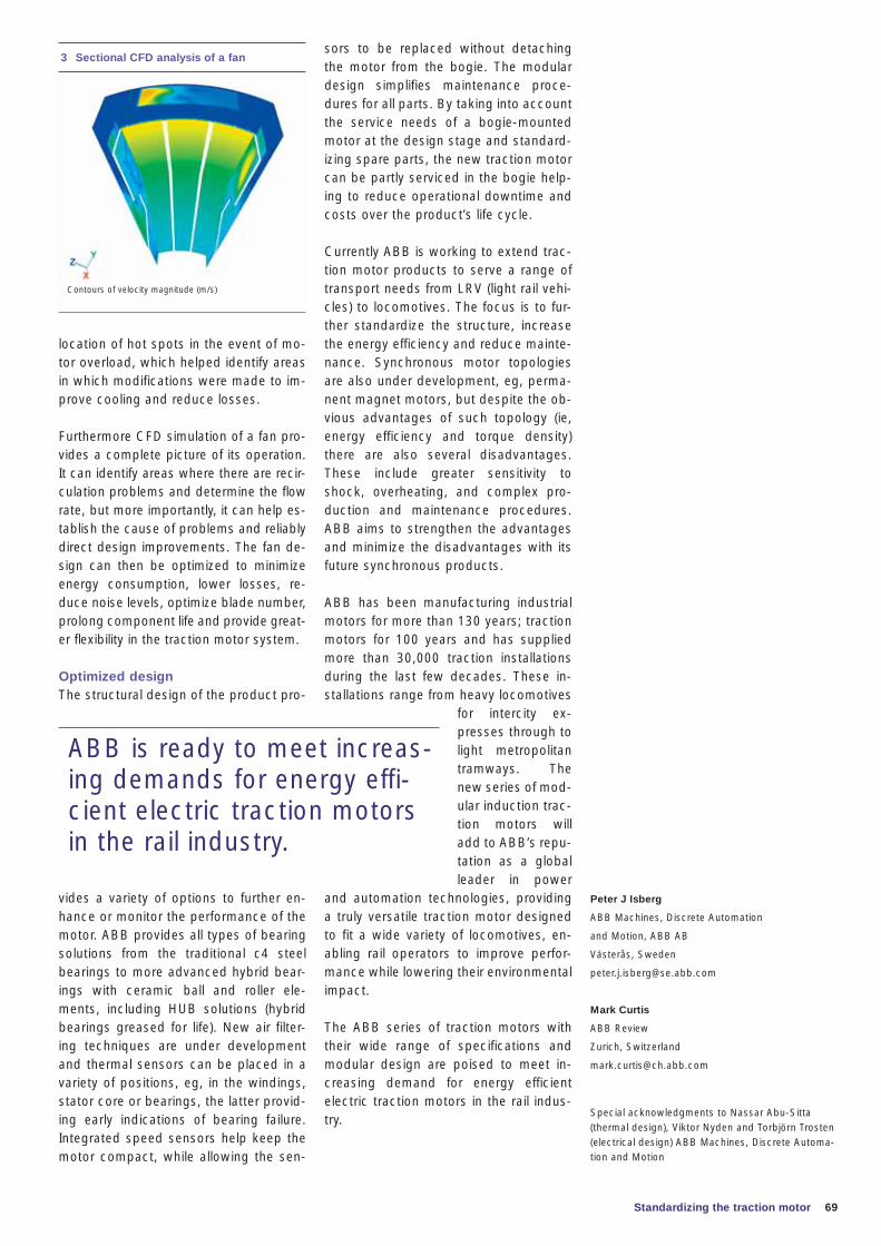
69Standardizing the traction motor
Peter J Isberg
ABB Machines, Discrete Automation
and Motion, ABB AB
Västerås, Sweden
Mark Curtis
ABB Review
Zurich, Switzerland
Special acknowledgments to Nassar Abu-Sitta (thermal design), Viktor Nyden and Torbjörn Trosten (electrical design) ABB Machines, Discrete Automa-tion and Motion
sors to be replaced without detaching the motor from the bogie. The modular design simplifies maintenance proce-dures for all parts. By taking into account the service needs of a bogie-mounted motor at the design stage and standard-izing spare parts, the new traction motor can be partly serviced in the bogie help-ing to reduce operational downtime and costs over the product’s life cycle.
Currently ABB is working to extend trac-tion motor products to serve a range of transport needs from LRV (light rail vehi-cles) to locomotives. The focus is to fur-ther standardize the structure, increase the energy efficiency and reduce mainte-nance. Synchronous motor topologies are also under development, eg, perma-nent magnet motors, but despite the ob-vious advantages of such topology (ie, energy efficiency and torque density) there are also several disadvantages. These include greater sensitivity to shock, overheating, and complex pro-duction and maintenance procedures. ABB aims to strengthen the advantages and minimize the disadvantages with its future synchronous products.
ABB has been manufacturing industrial motors for more than 130 years; traction motors for 100 years and has supplied more than 30,000 traction installations during the last few decades. These in-stallations range from heavy locomotives
for intercity ex-presses through to light metropolitan tramways. The new series of mod-ular induction trac-tion motors will add to ABB’s repu-tation as a global leader in power
and automation technologies, providing a truly versatile traction motor designed to fit a wide variety of locomotives, en-abling rail operators to improve perfor-mance while lowering their environmental impact.
The ABB series of traction motors with their wide range of specifications and modular design are poised to meet in-creasing demand for energy efficient electric traction motors in the rail indus-try.
location of hot spots in the event of mo-tor overload, which helped identify areas in which modifications were made to im-prove cooling and reduce losses.
Furthermore CFD simulation of a fan pro-vides a complete picture of its operation. It can identify areas where there are recir-culation problems and determine the fl ow rate, but more importantly, it can help es-tablish the cause of problems and reliably direct design improvements. The fan de-sign can then be optimized to minimize energy consumption, lower losses, re-duce noise levels, optimize blade number, prolong component life and provide great-er fl exibility in the traction motor system.
Optimized designThe structural design of the product pro-
vides a variety of options to further en-hance or monitor the performance of the motor. ABB provides all types of bearing solutions from the traditional c4 steel bearings to more advanced hybrid bear-ings with ceramic ball and roller ele-ments, including HUB solutions (hybrid bearings greased for life). New air filter-ing techniques are under development and thermal sensors can be placed in a variety of positions, eg, in the windings, stator core or bearings, the latter provid-ing early indications of bearing failure. Integrated speed sensors help keep the motor compact, while allowing the sen-
ABB is ready to meet increas-ing demands for energy effi-cient electric traction motors in the rail industry.
3 Sectional CFD analysis of a fan
Contours of velocity magnitude (m/s)
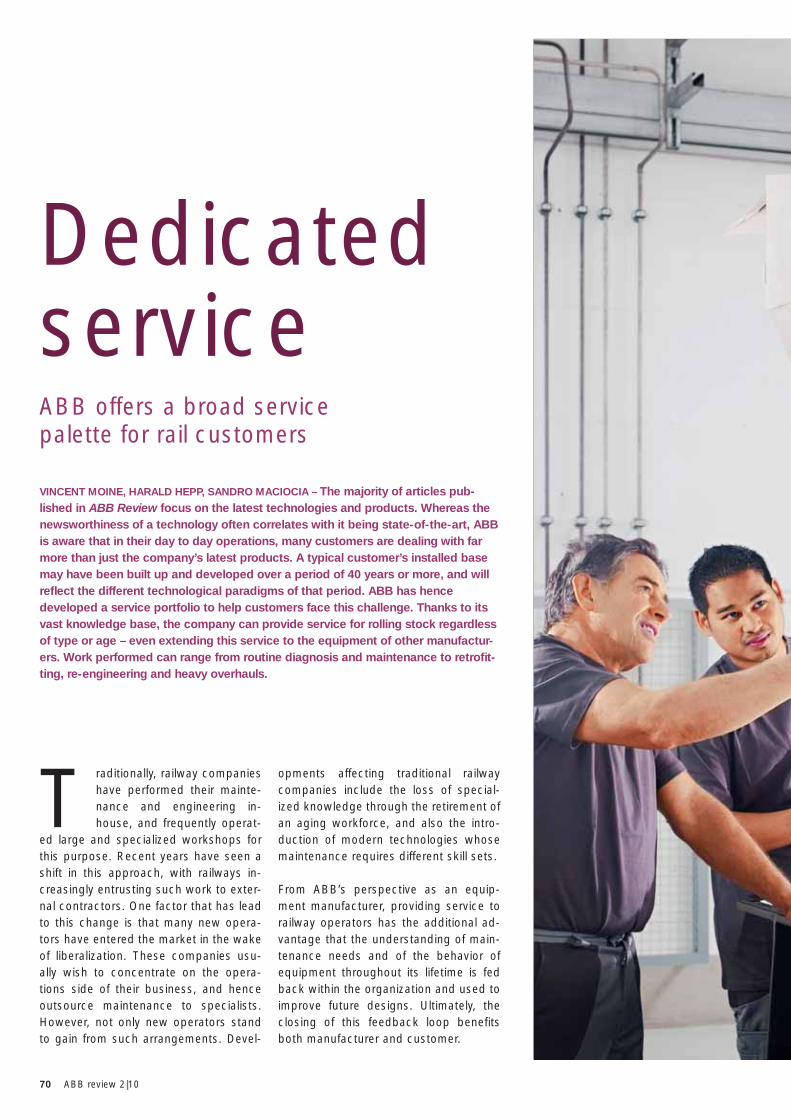
70 ABB review 2|10
VINCENT MOINE, HARALD HEPP, SANDRO MACIOCIA – The majority of articles pub-lished in ABB Review focus on the latest technologies and products. Whereas the newsworthiness of a technology often correlates with it being state-of-the-art, ABB is aware that in their day to day operations, many customers are dealing with far more than just the company’s latest products. A typical customer’s installed base may have been built up and developed over a period of 40 years or more, and will refl ect the different technological paradigms of that period. ABB has hence developed a service portfolio to help customers face this challenge. Thanks to its vast knowledge base, the company can provide service for rolling stock regardless of type or age – even extending this service to the equipment of other manufactur-ers. Work performed can range from routine diagnosis and maintenance to retrofi t-ting, re-engineering and heavy overhauls.
ABB offers a broad service palette for rail customers
Dedicated service
T raditionally, railway companies have performed their mainte-nance and engineering in-house, and frequently operat-
ed large and specialized workshops for this purpose. Recent years have seen a shift in this approach, with railways in-creasingly entrusting such work to exter-nal contractors. One factor that has lead to this change is that many new opera-tors have entered the market in the wake of liberalization. These companies usu-ally wish to concentrate on the opera-tions side of their business, and hence outsource maintenance to specialists. However, not only new operators stand to gain from such arrangements. Devel-
opments affecting traditional railway companies include the loss of special-ized knowledge through the retirement of an aging workforce, and also the intro-duction of modern technologies whose maintenance requires different skill sets.
From ABB’s perspective as an equip-ment manufacturer, providing service to railway operators has the additional ad-vantage that the understanding of main-tenance needs and of the behavior of equipment throughout its lifetime is fed back within the organization and used to improve future designs. Ultimately, the closing of this feedback loop benefits both manufacturer and customer.
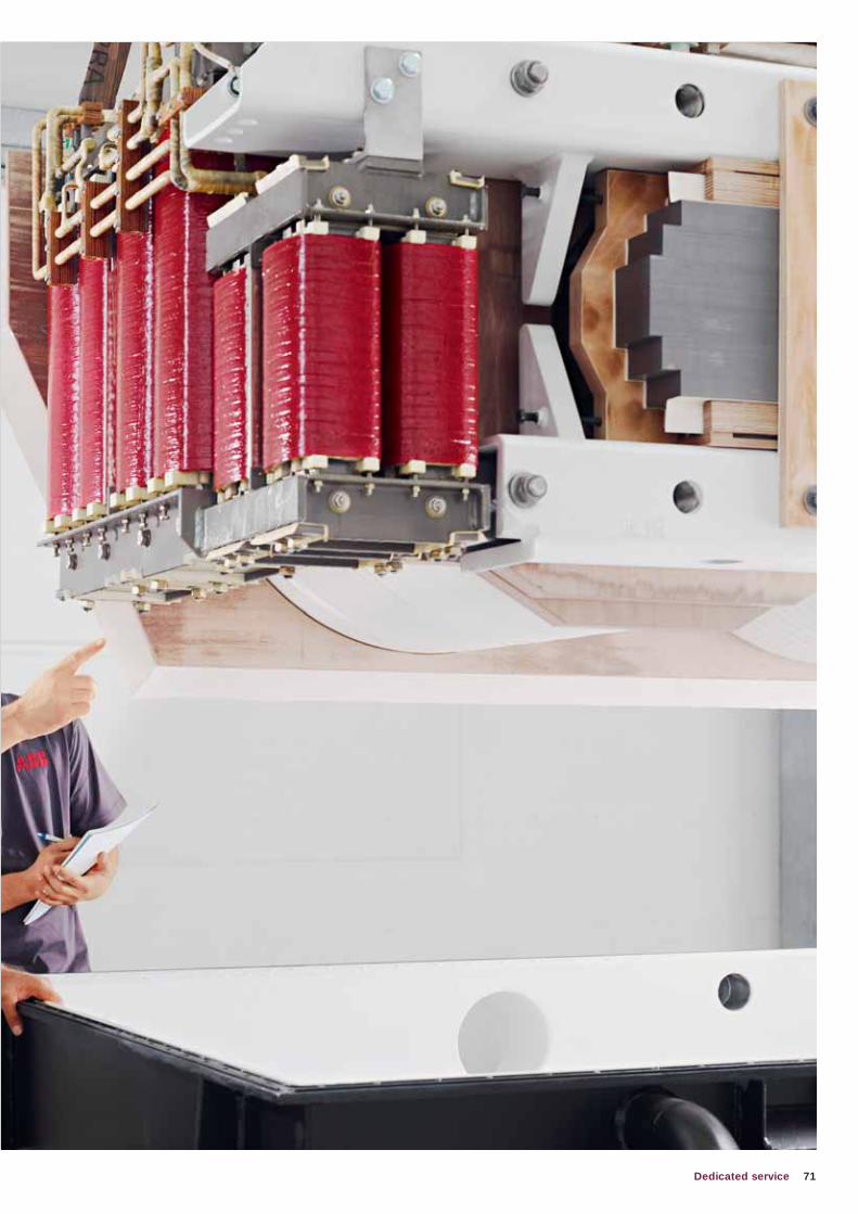
71Dedicated service
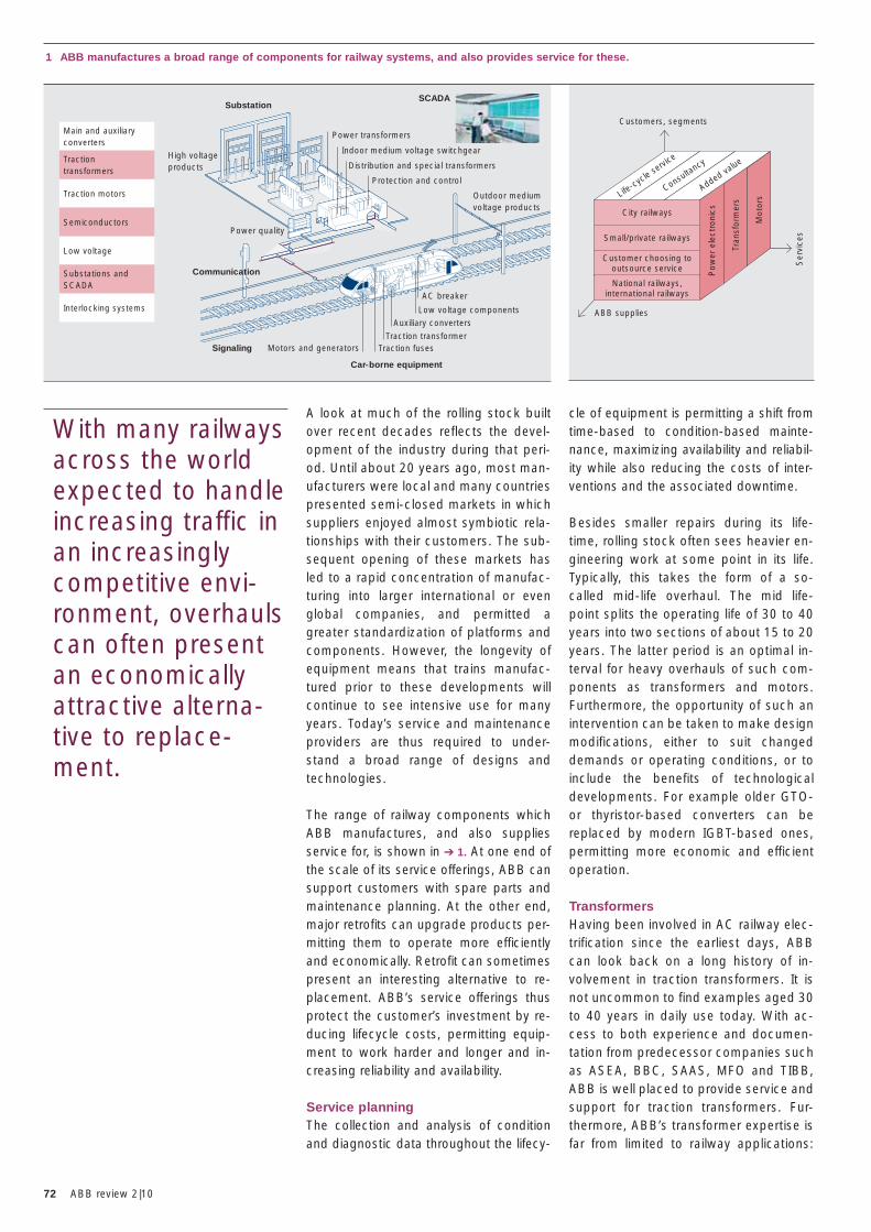
72 ABB review 2|10
A look at much of the rolling stock built over recent decades reflects the devel-opment of the industry during that peri-od. Until about 20 years ago, most man-ufacturers were local and many countries presented semi-closed markets in which suppliers enjoyed almost symbiotic rela-tionships with their customers. The sub-sequent opening of these markets has led to a rapid concentration of manufac-turing into larger international or even global companies, and permitted a greater standardization of platforms and components. However, the longevity of equipment means that trains manufac-tured prior to these developments will continue to see intensive use for many years. Today’s service and maintenance providers are thus required to under-stand a broad range of designs and technologies.
The range of railway components which ABB manufactures, and also supplies service for, is shown in ➔ 1. At one end of the scale of its service offerings, ABB can support customers with spare parts and maintenance planning. At the other end, major retrofi ts can upgrade products per-mitting them to operate more effi ciently and economically. Retrofi t can sometimes present an interesting alternative to re-placement. ABB’s service offerings thus protect the customer’s investment by re-ducing lifecycle costs, permitting equip-ment to work harder and longer and in-creasing reliability and availability.
Service planningThe collection and analysis of condition and diagnostic data throughout the lifecy-
With many railways across the world expected to handle increasing traffic in an increasingly competitive envi-ronment, overhauls can often present an economically attractive alterna-tive to replace-ment.
cle of equipment is permitting a shift from time-based to condition-based main te-nance, maximizing availability and reliabil-ity while also reducing the costs of inter-ventions and the associated downtime.
Besides smaller repairs during its life-time, rolling stock often sees heavier en-gineering work at some point in its life. Typically, this takes the form of a so-called mid-life overhaul. The mid life-point splits the operating life of 30 to 40 years into two sections of about 15 to 20 years. The latter period is an optimal in-terval for heavy overhauls of such com-ponents as transformers and motors. Furthermore, the opportunity of such an intervention can be taken to make design modifications, either to suit changed demands or operating conditions, or to include the benefits of technological developments. For example older GTO- or thyristor-based converters can be replaced by modern IGBT-based ones, permitting more economic and efficient operation.
TransformersHaving been involved in AC railway elec-trification since the earliest days, ABB can look back on a long history of in-volvement in traction transformers. It is not uncommon to find examples aged 30 to 40 years in daily use today. With ac-cess to both experience and documen-tation from predecessor companies such as ASEA, BBC, SAAS, MFO and TIBB, ABB is well placed to provide service and support for traction transformers. Fur-thermore, ABB’s transformer expertise is far from limited to railway applications:
City railways
Small/private railways
Customer choosing to outsource service
National railways, international railways
1 ABB manufactures a broad range of components for railway systems, and also provides service for these.
ABB supplies
Ser
vice
s
Customers, segments
Pow
er e
lect
roni
cs
Tran
sfor
mer
s
Mot
orsLife
-cycle servi
ce
Consultancy
Added value
Power transformersMain and auxiliaryconverters
Traction motors
Low voltage
Interlocking systems
Tractiontransformers
Semiconductors
Substations and SCADA
Power quality
High voltageproducts
Substation
Communication
Signaling
Car-borne equipment
SCADA
Indoor medium voltage switchgear
Distribution and special transformers
Protection and control
AC breaker
Low voltage componentsAuxiliary converters
Traction transformerTraction fusesMotors and generators
Outdoor medium voltage products
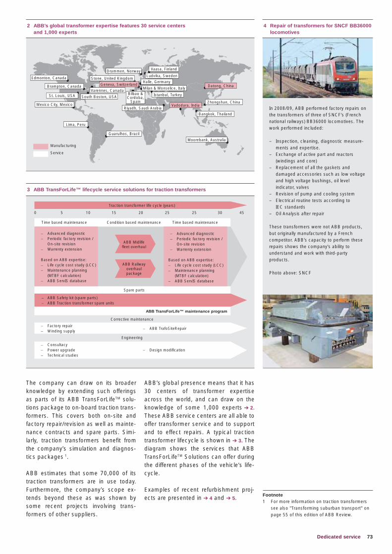
73Dedicated service
ABB’s global presence means that it has 30 centers of transformer expertise across the world, and can draw on the knowledge of some 1,000 experts ➔ 2.
These ABB service centers are all able to offer transformer service and to support and to effect repairs. A typical traction transformer lifecycle is shown in ➔ 3. The diagram shows the services that ABB TransForLifeTM Solutions can offer during the different phases of the vehicle’s life-cycle.
Examples of recent refurbishment proj-ects are presented in ➔ 4 and ➔ 5.
The company can draw on its broader knowledge by extending such offerings as parts of its ABB TransForLifeTM solu-tions package to on-board traction trans-formers. This covers both on-site and factory repair/revision as well as mainte-nance contracts and spare parts. Simi-larly, traction transformers benefit from the company’s simulation and diagnos-tics packages 1.
ABB estimates that some 70,000 of its traction transformers are in use today. Furthermore, the company’s scope ex-tends beyond these as was shown by some recent projects involving trans-formers of other suppliers.
4 Repair of transformers for SNCF BB36000 locomotives
In 2008/09, ABB performed factory repairs on the transformers of three of SNCF’s (French national railways) BB36000 locomotives. The work performed included:
– Inspection, cleaning, diagnostic measure-ments and expertise.
– Exchange of active part and reactors (windings and core)
– Replacement of all the gaskets and damaged accessories such as low voltage and high voltage bushings, oil level indicator, valves
– Revision of pump and cooling system – Electrical routine tests according to
IEC standards– Oil Analysis after repair
These transformers were not ABB products, but originally manufactured by a French competitor. ABB’s capacity to perform these repairs shows the company’s ability to understand and work with third-party products.
Photo above: SNCF
Footnote1 For more information on traction transformers
see also "Transforming suburban transport" on page 55 of this edition of ABB Review.
,
2 ABB’s global transformer expertise features 30 service centers and 1,000 experts
Drammen, Norway Vaasa, Finland
Ludvika, Sweden
Halle, Germany
Istanbul, Turkey
Stone, United Kingdom
Riyadh, Saudi Arabia
Zhongshan, China
Bangkok, Thailand
Moorebank, Australia
Guarulhos, Brazil
Lima, Peru
Edmonton, Canada
Brampton, Canada
Mexico City, Mexico
St. Louis, USA
Vadodara, India
Datong, ChinaGeneva, Switzerland
Varennes, Canada
South Boston, USABilbao & Cordoba,
Spain
Milan & Monselice, Italy
Manufacturing
Service
3 ABB TransForLife™ lifecycle service solutions for traction transformers
– Factory repair– Winding supply
– ABB TrafoSiteRepair
– Consultacy– Power upgrade– Technical studies
– Design modification
Traction transformer life cycle (years)
0 5 10 15 20 25 25 30 45
– Advanced diagnostic– Periodic factory revision /
On-site revision– Warrenty extension
Based on ABB expertise:– Life cycle cost study (LCC)– Maintenance planning
(MTBF calculation)– ABB ServIS database
– Advanced diagnostic– Periodic factory revision /
On-site revision– Warrenty extension
Based on ABB expertise:– Life cycle cost study (LCC)– Maintenance planning
(MTBF calculation)– ABB ServIS database
Time based maintenance Time based maintenanceCondition based maintenance
Spare parts
ABB TransForLife™ maintenance program
Corrective maintenance
Engineering
ABB Midlife fleet overhaul
ABB Railwayoverhaulpackage
– ABB Safety kit (spare parts)– ABB Traction transformer spare units
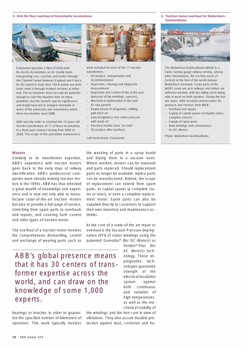
74 ABB review 2|10
the washing of parts in a spray booth and drying them in a vacuum oven. Where needed, motors can be rewound and parts replaced. Should replacement parts no longer be available, replica parts can be manufactured. Indeed, the scope of replacement can extend from spare parts, to capital spares (a complete sta-tor or rotor), or even a complete replace-ment motor. Spare parts can also be supplied directly to customers to support their own inventory and maintenance ac-tivities.
At the core of a state-of-the art repair or overhaul is the Vacuum Pressure Impreg-nation (VPI) of stator windings using the patented Gemodur® (for DC-Motors) or
Veridur®-Plus (for AC Motors) tech-nology. These im-pregnation tech-nologies guarantee strength of the electrical insulation system against both continuous and variation of high temperatures, as well as the me-chanical stability of
the windings and the iron core in view of vibrations. They also assure durable pro-tection against dust, corrosion and hu-
5 Mid-life fleet overhaul of Euroshuttle locomotives
Eurotunnel operates a fleet of dedicated Bo-Bo-Bo locomotives on its shuttle trains transporting cars, coaches and lorries through the Channel Tunnel between England and France. As the tunnel is more than 100 m below sea level, trains enter it through inclined sections at either end. The locomotives must not only be powerful enough to start the heaviest train on these gradients, but the tunnel’s special significance and length have led to stringent demands in terms of fire protection and redundancy which these locomotives must fulfill.
ABB won the order to overhaul the 15 years old traction transformers of 17 of these locomotives in a three-year contract lasting from 2006 to 2008. The scope of this preventive maintenance
6 Traction motor overhaul for Matterhorn-Gotthardbahn
The Matterhorn-Gotthardbahn (MGB) is a Swiss narrow gauge railway serving, among other destinations, the car-free resort of Zermatt at the foot of the world-famous Matterhorn mountain. Some parts of the MGB’s route are rack railways and others are adhesion worked, with the rolling stock being able to work on both systems. During the last two years, ABB received several orders for products and services from MGB:– Overhaul and repairs– Supply of capital spares (complete rotors,
complete stators)– Supply of spare parts– New windings and commutators
for DC-Motors
Photo: Matterhorn-Gotthardbahn
work included for each of the 17 traction transformers :– Oil analysis, interpretation and
recommendation– Inspection, cleaning and diagnostic
measurement– Inspection and control of the active part
(pressure of the windings, spacers)– Mechanical optimization of the tank
(O-ring gasket)– Replacement of all gaskets, refilling
with fresh oil– Special tightness test under pressure
with warm oil – Electrical routine tests “as-new”– Oil analysis after overhaul
Left-hand photo: Eurotunnel
MotorsSimilarly to its transformer expertise, ABB’s experience with traction motors goes back to the early days of railway electrification. ABB’s predecessor com-panies were already making traction mo-tors in the 1890s. ABB has thus inherited a great wealth of knowledge and experi-ence and is now not only able to manu-facture state-of-the-art traction motors but also to provide a full range of service, stretching from spare parts to overhauls and repairs, and covering both current and older types of traction motor.
The overhaul of a traction motor involves the comprehensive dismantling, control and exchange of wearing parts such as
bearings or brushes in order to guaran-tee the specified number of kilometers of operation. This work typically involves
ABB’s global presence means that it has 30 centers of trans-former expertise across the world, and can draw on the knowledge of some 1,000 experts.
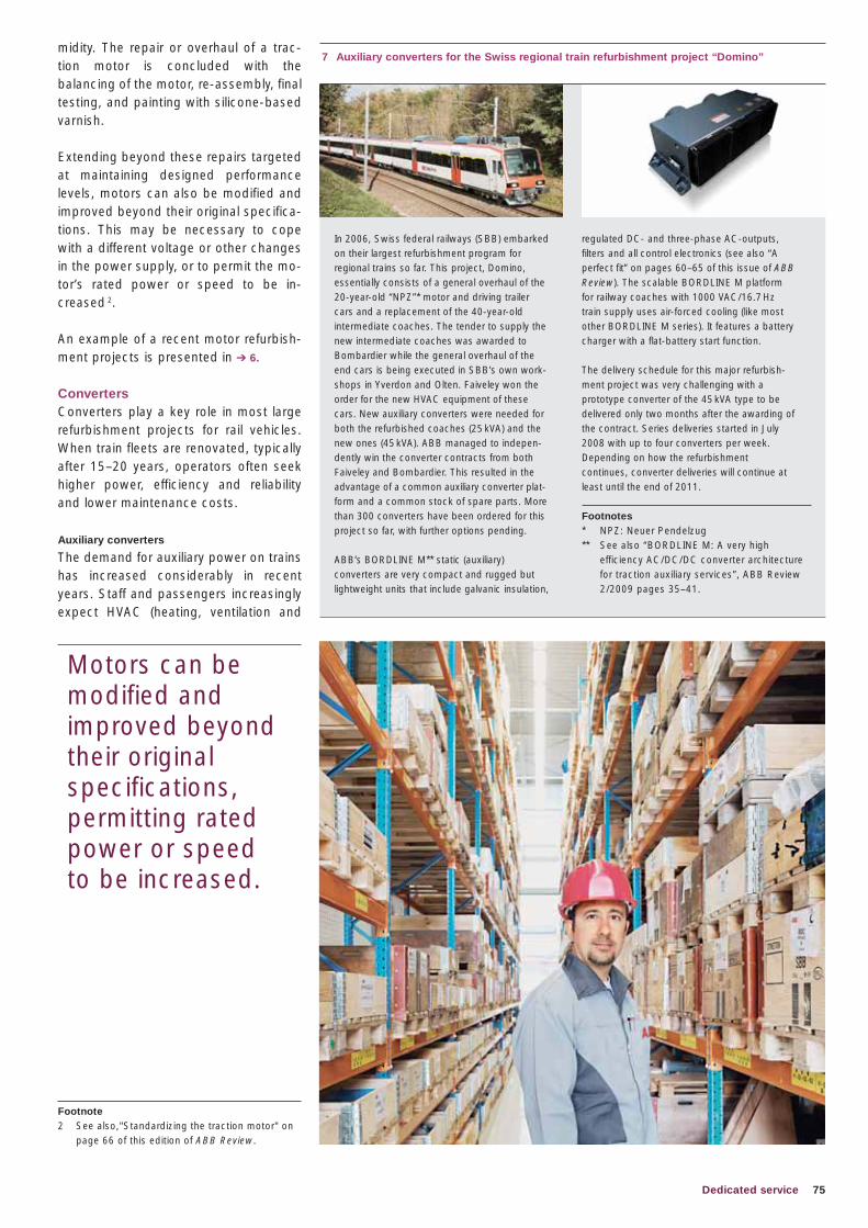
75Dedicated service
midity. The repair or overhaul of a trac-tion motor is concluded with the balancing of the motor, re-assembly, final testing, and painting with silicone-based varnish.
Extending beyond these repairs targeted at maintaining designed performance levels, motors can also be modified and improved beyond their original specifica-tions. This may be necessary to cope with a different voltage or other changes in the power supply, or to permit the mo-tor’s rated power or speed to be in-creased 2.
An example of a recent motor refurbish-ment projects is presented in ➔ 6.
ConvertersConverters play a key role in most large refurbishment projects for rail vehicles. When train fleets are renovated, typically after 15–20 years, operators often seek higher power, efficiency and reliability and lower maintenance costs.
Auxiliary converters
The demand for auxiliary power on trains has increased considerably in recent years. Staff and passengers increasingly expect HVAC (heating, ventilation and
7 Auxiliary converters for the Swiss regional train refurbishment project “Domino”
In 2006, Swiss federal railways (SBB) em barked on their largest refurbishment program for regio nal trains so far. This project, Domino, essentially consists of a general overhaul of the 20-year-old “NPZ”* motor and driving trailer cars and a replacement of the 40-year-old intermediate coaches. The tender to supply the new inter mediate coaches was awarded to Bombardier while the general overhaul of the end cars is being executed in SBB’s own work-shops in Yverdon and Olten. Faiveley won the order for the new HVAC equipment of these cars. New auxiliary converters were needed for both the refurbished coaches (25 kVA) and the new ones (45 kVA). ABB managed to indepen-dently win the converter contracts from both Faiveley and Bombardier. This resulted in the advantage of a common auxiliary converter plat-form and a common stock of spare parts. More than 300 converters have been ordered for this project so far, with further options pending.
ABB’s BORDLINE M** static (auxiliary) converters are very compact and rugged but lightweight units that include galvanic insulation,
regulated DC- and three-phase AC-outputs, fi lters and all control electronics (see also “A perfect fi t” on pages 60–65 of this issue of ABB Review). The scalable BORDLINE M platform for railway coaches with 1000 VAC/16.7 Hz train supply uses air-forced cooling (like most other BORDLINE M series). It features a battery charger with a fl at-battery start function.
The delivery schedule for this major refurbish-ment project was very challenging with a prototype converter of the 45 kVA type to be delivered only two months after the awarding of the contract. Series deliveries started in July 2008 with up to four converters per week. Depending on how the refurbishment continues, converter deliveries will continue at least until the end of 2011.
Footnotes* NPZ: Neuer Pendelzug** See also “BORDLINE M: A very high
efficiency AC/DC/DC converter architecture for traction auxiliary services”, ABB Review 2/2009 pages 35–41.
Motors can be modified and improved beyond their original specifications, permitting rated power or speed to be increased.
Footnote2 See also,"Standardizing the traction motor" on
page 66 of this edition of ABB Review.
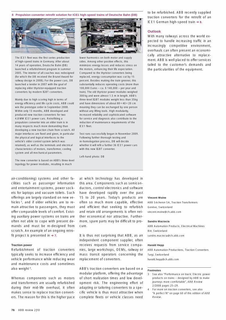
76 ABB review 2|10
to be refurbished. ABB recently supplied traction converters for the retrofit of an ICE1 German high-speed train ➔ 8.
OutlookWith many railways across the world ex-pected to handle increasing traffic in an increasingly competitive environment, overhauls can often present an economi-cally attractive alternative to replace-ment. ABB is well placed to offer services tailed to the customer’s demands and the particularities of the equipment.
Vincent Moine
ABB Sécheron SA, Traction Transformers
Genève, Switzerland
Sandro Maciocia
ABB Automation Products, Electrical Machines
Birr, Switzerland
Harald Hepp
ABB Automation Productions, Traction Converters
Turgi, Switzerland
Footnotes3 See also “Performance on track: Electric power
products on trains – designed by ABB to make journeys more comfortable”, ABB Review 2/2008 pages 25–29.
4 For more on traction converters, see also "A perfect fit" on page 60 of this edition of ABB Review.
at which technology has developed in this area. Components such as semicon-ductors, control electronics and software have developed rapidly over the past 15 to 20 years. Today’s products are often so much more capable, effective and efficient that seeking to refurbish and retain old arrangements is often nei-ther economical nor attractive. Further-more, spare parts may be difficult to pro-cure.
It is thus not surprising that ABB, as an independent component supplier, often receives requests from service compa-nies, large workshops, OEMs, railway or mass transit operators concerning the replacement of converters.
ABB’s traction converters are based on a modular platform, offering the advantage of short realization times and low devel-opment risk. The engineering effort of adapting or tailoring converters to a spe-cific vehicle is thus most attractive when complete fleets or vehicle classes need
air-conditioning) systems and other fa-cilities such as passenger information and entertainment systems, power sock-ets for laptops and vacuum toilets. Such offerings are largely standard on new ve-hicles 3, and if older vehicles are to re-main attractive to passengers, they must offer comparable levels of comfort. Exist-ing auxiliary power systems on trains are often not able to cope with present de-mands and must be re-designed from scratch. An example of an ongoing retro-fit project is presented in ➔ 7.
Traction power
Refurbishment of traction converters typically seeks to increase efficiency and vehicle performance while reducing wear and maintenance costs and sometimes also weight 4.
Whereas components such as motors and transformers are usually refurbished during their mid-life overhaul, it often makes sense to replace traction convert-ers. The reason for this is the higher pace
8 Propulsion converter retrofit solution for ICE1 high-speed trains of Deutsche Bahn (DB)
The ICE1 fleet was the first series production of high-speed trains in Germany. After about 14 years of operation, Deutsche Bahn (DB) launched a refurbishment program in summer 2005. The interior of all coaches was redesigned (for which the DB received the Brunel Award for railway design in 2008). For the power cars, DB launched a tender in 2007 with the goal of replacing older thyristor-equipped traction converters by modern IGBT converters.
Mainly due to high scoring high in terms of energy efficiency and life cycle costs, ABB could win the prototype order in September 2008. Within only 13 months, ABB developed and produced new traction converters for two 4.8 MW ICE1 power cars. Retrofitting a propulsion converter into an older train is in many respects much more demanding than developing a new traction chain from scratch. All major interfaces are fixed and given, in particular the physical and logical interfaces to the vehicle’s older control system (which was retained), as well as the terminals and electrical characteristics of motors, transformer, cooling system and all mechanical parameters.
The new converter is based on ABB’s three-level topology for power modules, resulting in much
lower harmonics on both motor and supply sides. Among other positive effects, this minimizes energy losses and reduces stress on the motors, enhancing their life expectation. Compared to the thyristor converters being replaced, energy consumption was cut by 15 percent. Besides making the train greener, this substantially reduces operating costs (more than 100,000 Euros – ca. $ 140,000 – per year and train). The old thyristor power modules weighed 300 kg and were almost 1.5 m in length. ABB’s three-level IGBT modules weight less than 35kg and have dimensions of about 80 × 40 × 20 cm meaning they can be exchanged by one person without any lifting tools. High modularity, increased reliability and sophisticated software for service and diagnosis also contribute to the reduction of maintenance requirements of the ICE1 fleet.
Test runs successfully began in November 2009. Following further thorough testing and re-homologation process, DB will decide whether it will refit a further 36 ICE1 power cars with this new IGBT converter.
Left-hand photo: DB
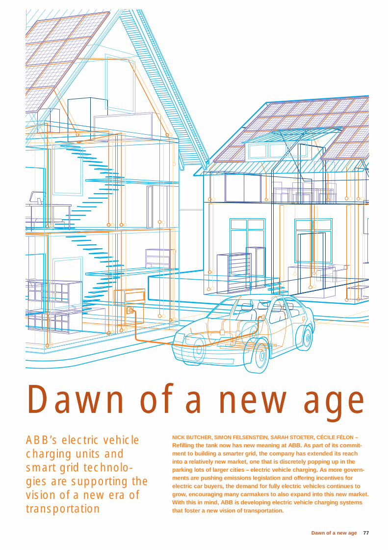
77Dawn of a new age
NICK BUTCHER, SIMON FELSENSTEIN, SARAH STOETER, CÉCILE FÉLON –
Refi lling the tank now has new meaning at ABB. As part of its commit-ment to building a smarter grid, the company has extended its reach into a relatively new market, one that is discretely popping up in the parking lots of larger cities – electric vehicle charging. As more govern-ments are pushing emissions legislation and offering incentives for electric car buyers, the demand for fully electric vehicles continues to grow, encouraging many carmakers to also expand into this new market. With this in mind, ABB is developing electric vehicle charging systems that foster a new vision of transportation.
ABB’s electric vehicle charging units and smart grid technolo-gies are supporting the vision of a new era of transportation
Dawn of a new age
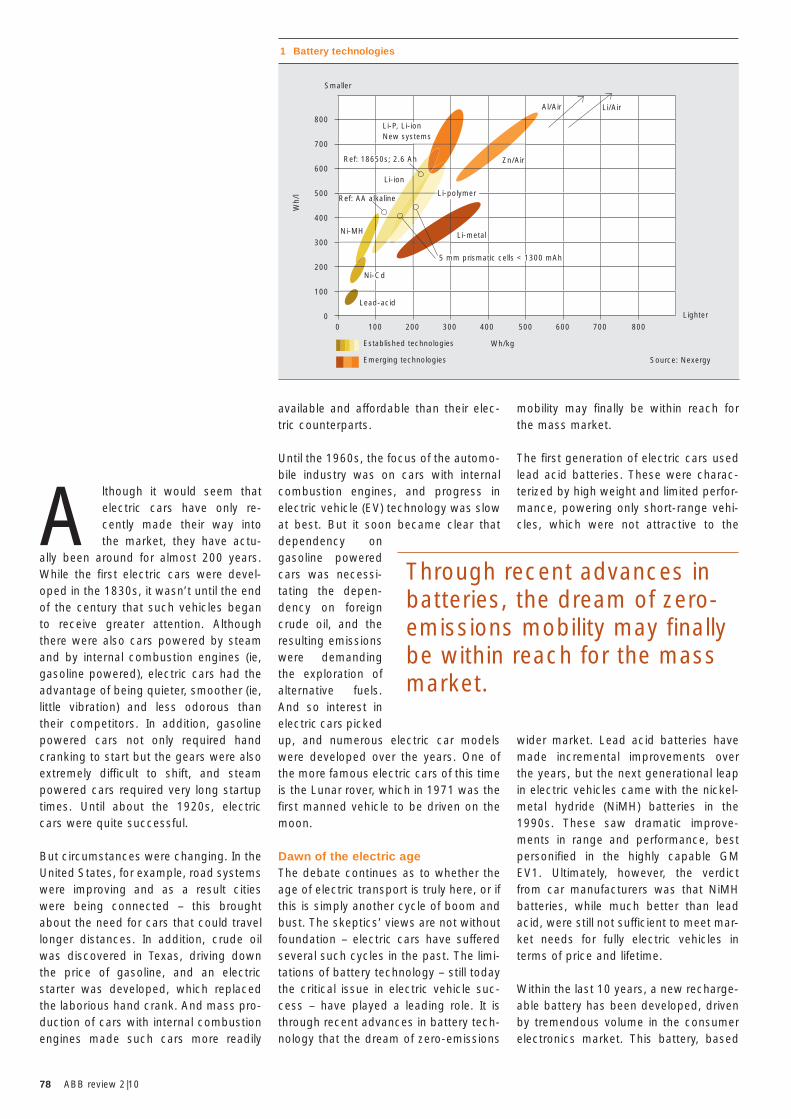
78 ABB review 2|10
mobility may finally be within reach for the mass market.
The first generation of electric cars used lead acid batteries. These were charac-terized by high weight and limited perfor-mance, powering only short-range vehi-cles, which were not attractive to the
wider market. Lead acid batteries have made incremental improvements over the years, but the next generational leap in electric vehicles came with the nickel-metal hydride (NiMH) batteries in the 1990s. These saw dramatic improve-ments in range and performance, best personified in the highly capable GM EV1. Ultimately, however, the verdict from car manufacturers was that NiMH batteries, while much better than lead acid, were still not sufficient to meet mar-ket needs for fully electric vehicles in terms of price and lifetime.
Within the last 10 years, a new recharge-able battery has been developed, driven by tremendous volume in the consumer electronics market. This battery, based
available and affordable than their elec-tric counterparts.
Until the 1960s, the focus of the automo-bile industry was on cars with internal combustion engines, and progress in electric vehicle (EV) technology was slow at best. But it soon became clear that dependency on gasoline powered cars was necessi-tating the depen-dency on foreign crude oil, and the resulting emissions were demanding the exploration of alternative fuels. And so interest in electric cars picked up, and numerous electric car models were developed over the years. One of the more famous electric cars of this time is the Lunar rover, which in 1971 was the first manned vehicle to be driven on the moon.
Dawn of the electric ageThe debate continues as to whether the age of electric transport is truly here, or if this is simply another cycle of boom and bust. The skeptics’ views are not without foundation – electric cars have suffered several such cycles in the past. The limi-tations of battery technology – still today the critical issue in electric vehicle suc-cess – have played a leading role. It is through recent advances in battery tech-nology that the dream of zero-emissions
A lthough it would seem that electric cars have only re-cently made their way into the market, they have actu-
ally been around for almost 200 years. While the first electric cars were devel-oped in the 1830s, it wasn’t until the end of the century that such vehicles began to receive greater attention. Although there were also cars powered by steam and by internal combustion engines (ie, gasoline powered), electric cars had the advantage of being quieter, smoother (ie, little vibration) and less odorous than their competitors. In addition, gasoline powered cars not only required hand cranking to start but the gears were also extremely difficult to shift, and steam powered cars required very long startup times. Until about the 1920s, electric cars were quite successful.
But circumstances were changing. In the United States, for example, road systems were improving and as a result cities were being connected – this brought about the need for cars that could travel longer distances. In addition, crude oil was discovered in Texas, driving down the price of gasoline, and an electric starter was developed, which replaced the laborious hand crank. And mass pro-duction of cars with internal combustion engines made such cars more readily
1 Battery technologies
Wh/kg
Lighter
Smaller
Li-P, Li-ionNew systems
Li-ion
Zn/Air
Al/Air Li/Air
Ref: 18650s; 2.6 Ah
Ref: AA alkaline
Ni-MH
Ni-Cd
Lead-acid
Li-polymer
Li-metal
800
700
600
500
400
300
200
100
0
Wh/
l
0 100 200 300 400 500 600 700 800
5 mm prismatic cells < 1300 mAh
Established technologies
Emerging technologies
Through recent advances in batteries, the dream of zero-emissions mobility may finally be within reach for the mass market.
Source: Nexergy
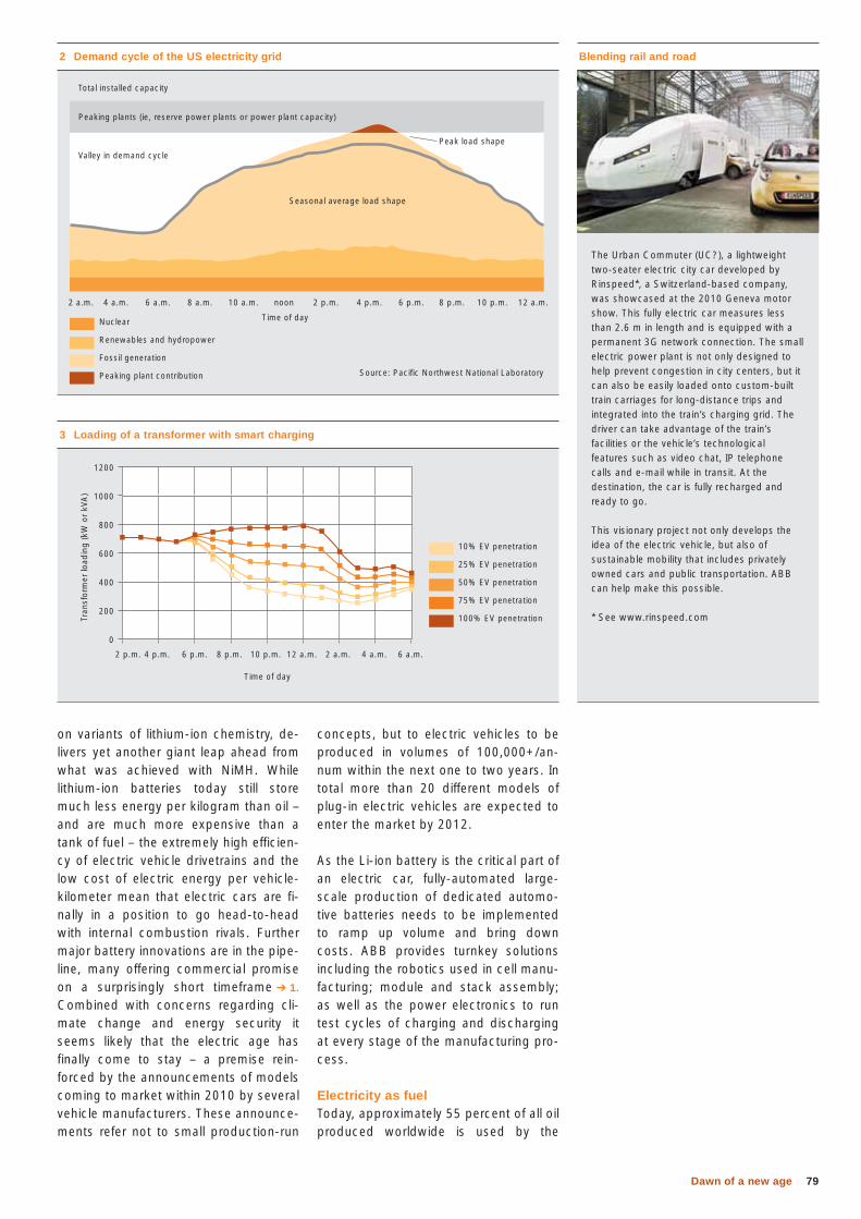
79Dawn of a new age
concepts, but to electric vehicles to be produced in volumes of 100,000+/an-num within the next one to two years. In total more than 20 different models of plug-in electric vehicles are expected to enter the market by 2012.
As the Li-ion battery is the critical part of an electric car, fully-automated large-scale production of dedicated automo-tive batteries needs to be implemented to ramp up volume and bring down costs. ABB provides turnkey solutions including the robotics used in cell manu-facturing; module and stack assembly; as well as the power electronics to run test cycles of charging and discharging at every stage of the manufacturing pro-cess.
Electricity as fuelToday, approximately 55 percent of all oil produced worldwide is used by the
on variants of lithium-ion chemistry, de-livers yet another giant leap ahead from what was achieved with NiMH. While lithium-ion batteries today still store much less energy per kilogram than oil – and are much more expensive than a tank of fuel – the extremely high efficien-cy of electric vehicle drivetrains and the low cost of electric energy per vehicle-kilometer mean that electric cars are fi-nally in a position to go head-to-head with internal combustion rivals. Further major battery innovations are in the pipe-line, many offering commercial promise on a surprisingly short timeframe ➔ 1. Combined with concerns regarding cli-mate change and energy security it seems likely that the electric age has finally come to stay – a premise rein-forced by the announcements of models coming to market within 2010 by several vehicle manufacturers. These announce-ments refer not to small production-run
Blending rail and road
The Urban Commuter (UC?), a lightweight two-seater electric city car developed by Rinspeed*, a Switzerland-based company, was showcased at the 2010 Geneva motor show. This fully electric car measures less than 2.6 m in length and is equipped with a permanent 3G network connection. The small electric power plant is not only designed to help prevent congestion in city centers, but it can also be easily loaded onto custom-built train carriages for long-distance trips and integrated into the train’s charging grid. The driver can take advantage of the train’s facilities or the vehicle’s technological features such as video chat, IP telephone calls and e-mail while in transit. At the destination, the car is fully recharged and ready to go.
This visionary project not only develops the idea of the electric vehicle, but also of sustainable mobility that includes privately owned cars and public transportation. ABB can help make this possible.
* See www.rinspeed.com
2 Demand cycle of the US electricity grid
Source: Pacific Northwest National Laboratory
Valley in demand cycle
Seasonal average load shape
Time of day
Peak load shape
Peaking plants (ie, reserve power plants or power plant capacity)
Total installed capacity
2 a.m. 4 a.m. 6 a.m. 8 a.m. 10 a.m. noon 2 p.m. 4 p.m. 6 p.m. 8 p.m. 10 p.m. 12 a.m.
Nuclear
Renewables and hydropower
Fossil generation
Peaking plant contribution
3 Loading of a transformer with smart charging
1200
1000
800
600
400
200
0
Tran
sfor
mer
load
ing
(kW
or
kVA
)
Time of day
10% EV penetration
25% EV penetration
50% EV penetration
75% EV penetration
100% EV penetration
2 p.m. 4 p.m. 6 p.m. 8 p.m. 10 p.m. 12 a.m. 2 a.m. 4 a.m. 6 a.m.
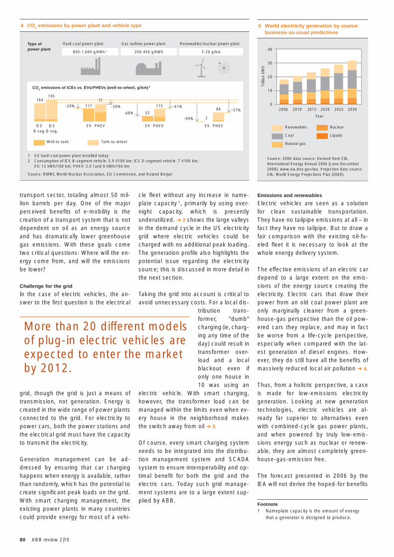
80 ABB review 2|10
Emissions and renewables
Electric vehicles are seen as a solution for clean sustainable transportation. They have no tailpipe emissions at all – in fact they have no tailpipe. But to draw a fair comparison with the existing oil-fu-eled fleet it is necessary to look at the whole energy delivery system.
The effective emissions of an electric car depend to a large extent on the emis-sions of the energy source creating the electricity. Electric cars that draw their power from an old coal power plant are only marginally cleaner from a green-house-gas perspective than the oil pow-ered cars they replace, and may in fact be worse from a life-cycle perspective, especially when compared with the lat-est generation of diesel engines. How-ever, they do still have all the benefits of massively reduced local air pollution ➔ 4.
Thus, from a holistic perspective, a case is made for low-emissions electricity generation. Looking at new generation technologies, electric vehicles are al-ready far superior to alternatives even with combined-cycle gas power plants, and when powered by truly low-emis-sions energy such as nuclear or renew-able, they are almost completely green-house-gas-emission free.
The forecast presented in 2006 by the IEA will not derive the hoped-for benefits
cle fleet without any increase in name-plate capacity 1, primarily by using over-night capacity, which is presently underutilized. ➔ 2 shows the large valleys in the demand cycle in the US electricity grid where electric vehicles could be charged with no additional peak loading. The generation profile also highlights the potential issue regarding the electricity source; this is discussed in more detail in the next section.
Taking the grid into account is critical to avoid unnecessary costs. For a local dis-
tribution trans-former, "dumb" charging (ie, charg-ing any time of the day) could result in transformer over-load and a local blackout even if only one house in 10 was using an
electric vehicle. With smart charging, however, the transformer load can be managed within the limits even when ev-ery house in the neighborhood makes the switch away from oil ➔ 3.
Of course, every smart charging system needs to be integrated into the distribu-tion management system and SCADA system to ensure interoperability and op-timal benefit for both the grid and the electric cars. Today such grid manage-ment systems are to a large extent sup-plied by ABB.
transport sector, totaling almost 50 mil-lion barrels per day. One of the major perceived benefits of e-mobility is the creation of a transport system that is not dependent on oil as an energy source and has dramatically lower greenhouse gas emissions. With these goals come two critical questions: Where will the en-ergy come from, and will the emissions be lower?
Challenge for the grid
In the case of electric vehicles, the an-swer to the first question is the electrical
grid, though the grid is just a means of transmission, not generation. Energy is created in the wide range of power plants connected to the grid. For electricity to power cars, both the power stations and the electrical grid must have the capacity to transmit the electricity.
Generation management can be ad-dressed by ensuring that car charging happens when energy is available, rather than randomly, which has the potential to create significant peak loads on the grid. With smart charging management, the existing power plants in many countries could provide energy for most of a vehi-
4 CO2 emissions by power plant and vehicle type
Well-to-tank Tank-to-wheel
Type of power plant
Hard-coal power plant
CO2 emissions of ICEs vs. EVs/PHEVs (well-to-wheel, g/km) 2
ICEB-seg.
ICED-seg.
164195
11715
-29% -20% -41%-57%84
2-99%52
115
-68%
EV EV EVPHEV PHEV PHEV
1 EU hard-coal power plant installed today2 Consumption of ICE B-segment vehicle: 5.9 l/100 km; ICE D-segment vehicle: 7 l/100 km; EV: 13 kWh/100 km; PHEV: 3.0 l and 8 kWh/100 km
Source: BMWI, World Nuclear Association, EU Commission, and Roland Berger
800-1,000 g/kWh 1 350-450 g/kWh 5-20 g/km
Gas turbine power plant Renewables/nuclear power plant
More than 20 different models of plug-in electric vehicles are expected to enter the market by 2012.
Footnote1 Nameplate capacity is the amount of energy
that a generator is designed to produce.
5 World electricity generation by source: business-as-usual predictions
40
30
20
10
0
Renewables
Coal
Natural gas
Nuclear
Liquids
Trill
ion
kWh
Year
2006 2010 2015 2020 2025 2030
Source: 2006 data source: Derived from EIA, International Energy Annual 2006 (June-December 2008), www.eia.doe.gov/iea. Projection data source: EIA, World Energy Projections Plus (2009).
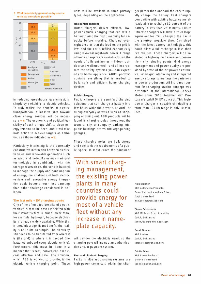
81Dawn of a new age
ger (rather than onboard the car) to rap-idly charge the battery. Fast chargers compatible with existing batteries are al-ready able to recharge 80 percent of the battery in less than 25 minutes. Future ultrafast chargers will allow a ”fuel stop” equivalent for EVs, charging the car in the shortest possible time. Combined with the latest battery technologies, this could allow a full recharge in less than five minutes. These chargers will be in-stalled in highway rest areas and conve-nient city refueling points. Grid energy management and power quality are pro-vided by state-of-the-art power electron-ics, smart grid interfacing and integrated energy storage to manage the variations in power production. ABB's direct-cur-rent fast-charging station concept was presented at the International Geneva Motor Show 2010, together with Pro-toscar’s LAMPO2 EV concept. This high-power charger is capable of refueling a more than 100 km range in only 10 min-utes.
Nick Butcher
ABB Automation Products,
Power Electronics and MV Drives
Turgi, Switzerland
Simon Felsenstein
ABB ISI Smart Grids, E-mobility
Zurich, Switzerland
Sarah Stoeter
ABB Review
Zurich, Switzerland
Cécile Félon
ABB Power Products
Geneva, Switzerland
units will be available in three primary types, depending on the application.
Residential charging
Home chargers deliver efficient, low-power vehicle charging that can refill a battery during the night, reaching full ca-pacity before morning. Charging over-night ensures that the load on the grid is low, and the car is refilled economically using low-cost night-rate power. A range of home chargers are available to suit the needs of different homes – indoor, out-door and wall mounted – and all incorpo-rate the safety systems you can expect of any home appliance. ABB's portfolio contains everything that is needed to build safe and efficient home charging devices.
Public charging
Public chargers are semi-fast charging solutions that can charge a battery in a few hours while the driver is at work, or during everyday activities such as shop-ping or dining out. ABB products will be found in charging poles throughout the town or city at company parking lots, public buildings, stores and large parking garages.
These charging poles are built strong and safe to fit the requirements of a pub-lic space. In most cases the consumer
will pay for the electricity used, so the charging pole will include an authentica-tion and/or payment system.
Fast and ultrafast charging
Fast and ultrafast charging systems use high-power converters within the char-
in reducing greenhouse gas emissions simply by switching to electric vehicles. To truly realize the benefits of electric transportation, a massive shift toward clean energy sources will be neces-sary ➔ 5. The economic and political fea-sibility of such a huge shift to clean en-ergy remains to be seen, and it will take bold action to achieve targets as ambi-tious as those indicated in ➔ 6.
Particularly interesting is the potentially constructive interaction between electric vehicles and renewable generation such as wind and solar. By using smart grid technologies in combination with the storage reservoir (ie, the vehicle battery) to manage the supply and consumption of energy, the challenge of both electric vehicle and renewable energy integra-tion could become much less daunting than either challenge considered in iso-lation.
The last mile – EV charging pointsOne of the often cited benefits of electric vehicles is that the cost associated with their infrastructure is much lower than, for example, hydrogen, because electric-ity is already widely available. While this is certainly a significant benefit, the real-ity is not quite so simple. The electricity still needs to be transferred from where it is (the grid) to where it is needed (the batteries onboard every electric vehicle). Furthermore, this must be done in a manner that is fast, convenient, simple, cost effective and safe. The solution, which ABB is working to provide, is the electric vehicle charging point. These
With smart charg-ing management, the existing power plants in many countries could provide energy for most of a vehicle fleet without any increase in name-plate capacity.
6 World electricity generation by source: ultralow emissions possible
2008 2020
100
80
60
40
20
0
Non-hydro renewables
Hydropower
Nuclear
Natural gas
Oil
Coal
Biomass
Geothermal
Solar
Wind
Per
cent
Source: EPI and IEA
40.3 20.8
11.4
4.8
37.7
13.5
6.35.6
5.2
19.1
13.7
17.5
4.1
Year
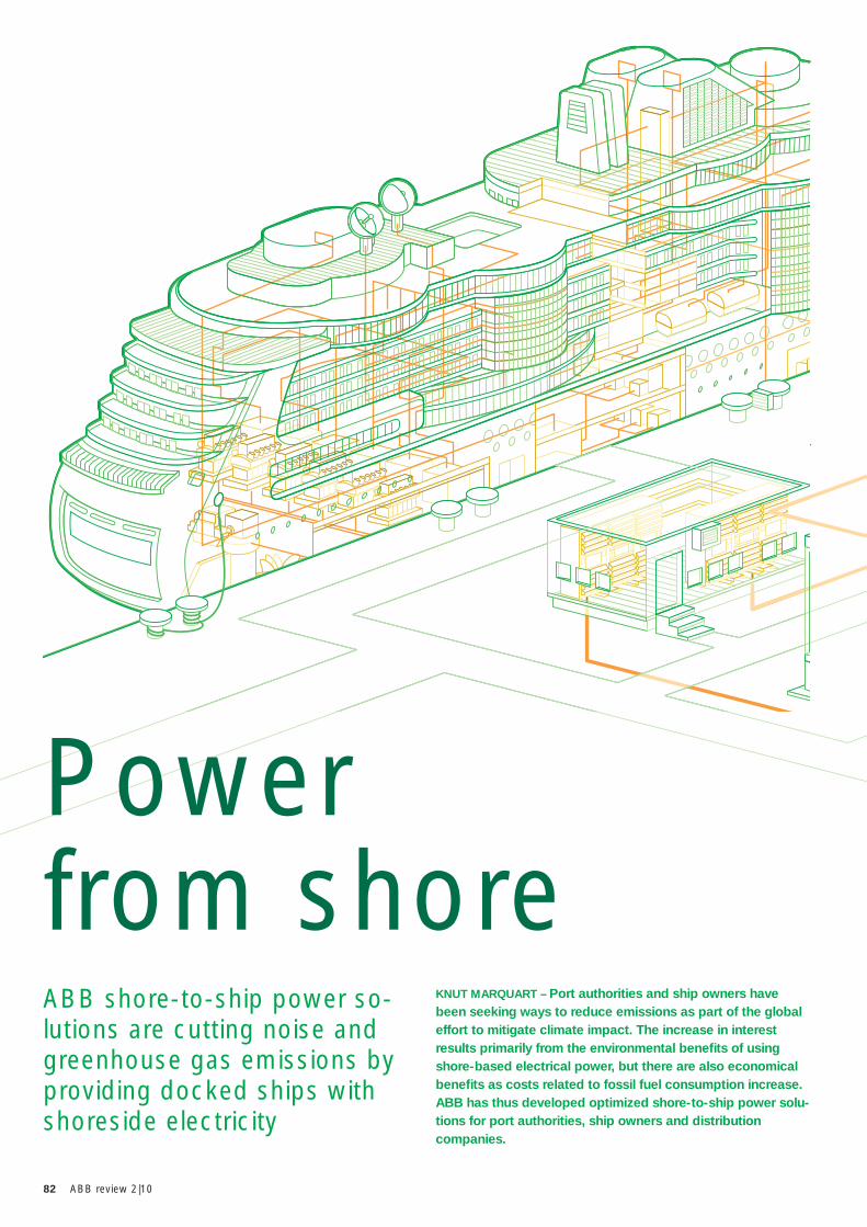
82 ABB review 2|10
KNUT MARQUART – Port authorities and ship owners have been seeking ways to reduce emissions as part of the global effort to mitigate climate impact. The increase in interest results primarily from the environmental benefi ts of using shore-based electrical power, but there are also economical benefi ts as costs related to fossil fuel consumption increase. ABB has thus developed optimized shore-to-ship power solu-tions for port authorities, ship owners and distribution companies.
ABB shore-to-ship power so-lutions are cutting noise and greenhouse gas emissions by providing docked ships with shoreside electricity
Power from shore
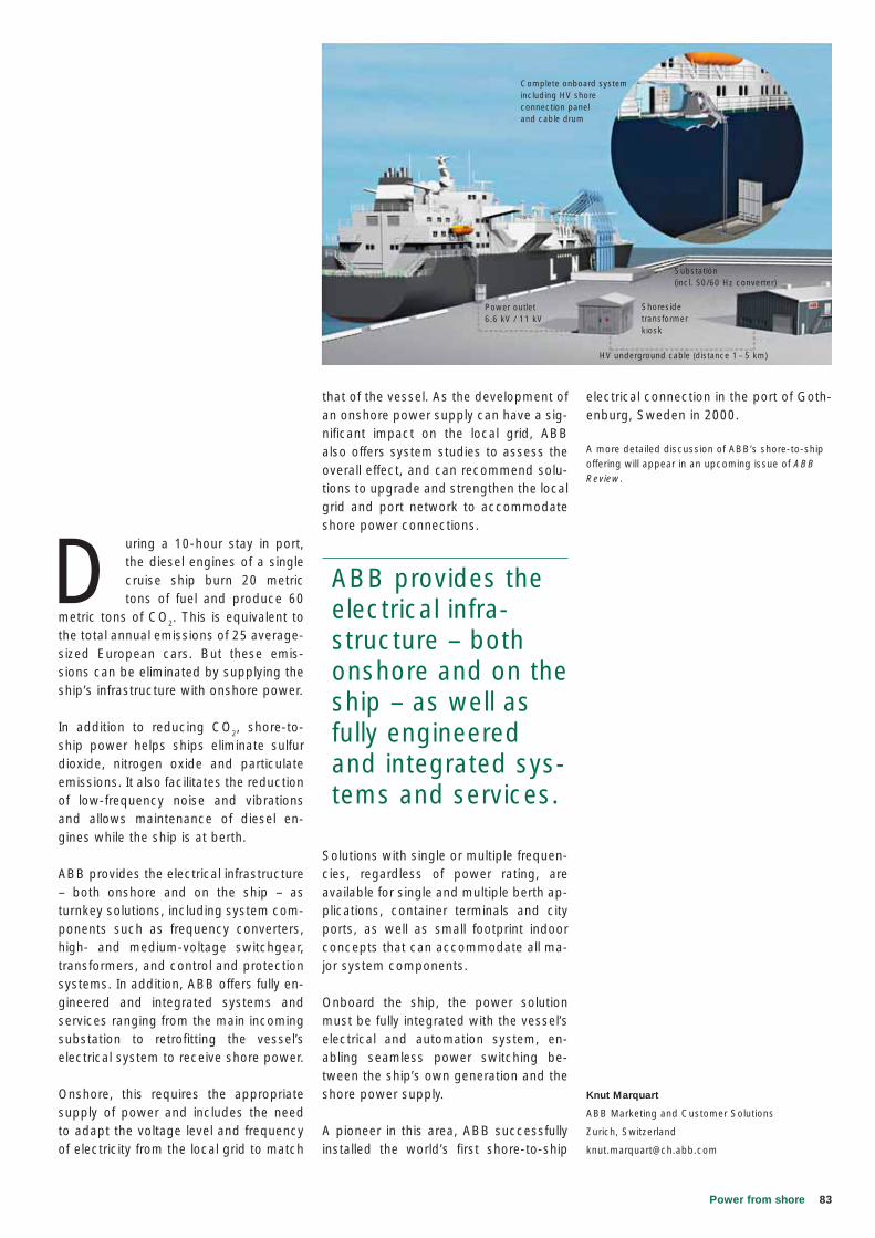
83Power from shore
electrical connection in the port of Goth-enburg, Sweden in 2000.
A more detailed discussion of ABB’s shore-to-ship offering will appear in an upcoming issue of ABB Review.
Knut Marquart
ABB Marketing and Customer Solutions
Zurich, Switzerland
that of the vessel. As the development of an onshore power supply can have a sig-nificant impact on the local grid, ABB also offers system studies to assess the overall effect, and can recommend solu-tions to upgrade and strengthen the local grid and port network to accommodate shore power connections.
Solutions with single or multiple frequen-cies, regardless of power rating, are available for single and multiple berth ap-plications, container terminals and city ports, as well as small footprint indoor concepts that can accommodate all ma-jor system components.
Onboard the ship, the power solution must be fully integrated with the vessel’s electrical and automation system, en-abling seamless power switching be-tween the ship’s own generation and the shore power supply.
A pioneer in this area, ABB successfully installed the world’s first shore-to-ship
D uring a 10-hour stay in port, the diesel engines of a single cruise ship burn 20 metric tons of fuel and produce 60
metric tons of CO2. This is equivalent to the total annual emissions of 25 average-sized European cars. But these emis-sions can be eliminated by supplying the ship’s infrastructure with onshore power.
In addition to reducing CO2, shore-to-ship power helps ships eliminate sulfur dioxide, nitrogen oxide and particulate emissions. It also facilitates the reduction of low-frequency noise and vibrations and allows maintenance of diesel en-gines while the ship is at berth.
ABB provides the electrical infrastructure – both onshore and on the ship – as turnkey solutions, including system com-ponents such as frequency converters, high- and medium-voltage switchgear, transformers, and control and protection systems. In addition, ABB offers fully en-gineered and integrated systems and services ranging from the main incoming substation to retrofitting the vessel’s electrical system to receive shore power.
Onshore, this requires the appropriate supply of power and includes the need to adapt the voltage level and frequency of electricity from the local grid to match
ABB provides the electrical infra-structure – both onshore and on the ship – as well as fully engineered and integrated sys-tems and services.
Complete onboard systemincluding HV shoreconnection panel and cable drum
Power outlet6.6 kV / 11 kV
Substation (incl. 50/60 Hz converter)
HV underground cable (distance 1– 5 km)
Shoresidetransformer kiosk
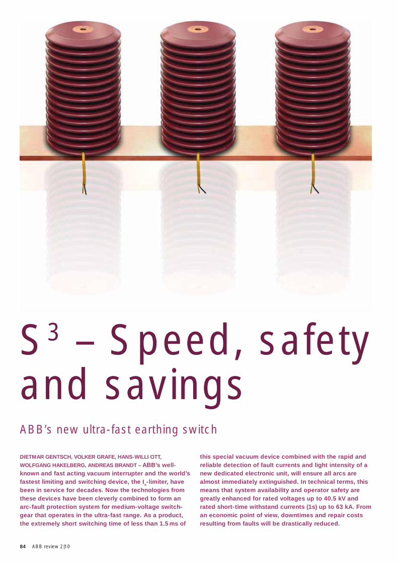
84 ABB review 2|10
this special vacuum device combined with the rapid and reliable detection of fault currents and light intensity of a new dedicated electronic unit, will ensure all arcs are almost immediately extinguished. In technical terms, this means that system availability and operator safety are greatly enhanced for rated voltages up to 40.5 kV and rated short-time withstand currents (1s) up to 63 kA. From an economic point of view, downtimes and repair costs resulting from faults will be drastically reduced.
DIETMAR GENTSCH, VOLKER GRAFE, HANS-WILLI OTT,
WOLFGANG HAKELBERG, ANDREAS BRANDT – ABB’s well-known and fast acting vacuum interrupter and the world’s fastest limiting and switching device, the Is-limiter, have been in service for decades. Now the technologies from these devices have been cleverly combined to form an arc-fault protection system for medium-voltage switch-gear that operates in the ultra-fast range. As a product, the extremely short switching time of less than 1.5 ms of
S3 – Speed, safety and savingsABB’s new ultra-fast earthing switch
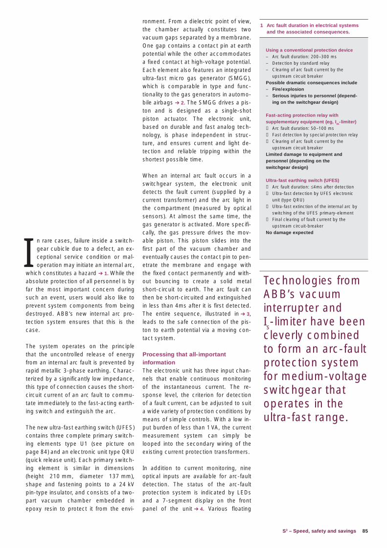
85S3 – Speed, safety and savings
ronment. From a dielectric point of view, the chamber actually constitutes two vacuum gaps separated by a membrane. One gap contains a contact pin at earth potential while the other accommodates a fixed contact at high-voltage potential. Each element also features an integrated ultra-fast micro gas generator (SMGG), which is comparable in type and func-tionality to the gas generators in automo-bile airbags ➔ 2. The SMGG drives a pis-ton and is designed as a single-shot piston actuator. The electronic unit, based on durable and fast analog tech-nology, is phase independent in struc-ture, and ensures current and light de-tection and reliable tripping within the shortest possible time.
When an internal arc fault occurs in a switchgear system, the electronic unit detects the fault current (supplied by a current transformer) and the arc light in the compartment (measured by optical sensors). At almost the same time, the gas generator is activated. More specifi-cally, the gas pressure drives the mov-able piston. This piston slides into the first part of the vacuum chamber and eventually causes the contact pin to pen-etrate the membrane and engage with the fixed contact permanently and with-out bouncing to create a solid metal short-circuit to earth. The arc fault can then be short-circuited and extinguished in less than 4ms after it is first detected. The entire sequence, illustrated in ➔ 3, leads to the safe connection of the pis-ton to earth potential via a moving con-tact system.
Processing that all-important informationThe electronic unit has three input chan-nels that enable continuous monitoring of the instantaneous current. The re-sponse level, the criterion for detection of a fault current, can be adjusted to suit a wide variety of protection conditions by means of simple controls. With a low in-put burden of less than 1 VA, the current measurement system can simply be looped into the secondary wiring of the existing current protection transformers.
In addition to current monitoring, nine optical inputs are available for arc-fault detection. The status of the arc-fault protection system is indicated by LEDs and a 7-segment display on the front panel of the unit ➔ 4. Various floating
I n rare cases, failure inside a switch-gear cubicle due to a defect, an ex-ceptional service condition or mal-operation may initiate an internal arc,
which constitutes a hazard ➔ 1. While the absolute protection of all personnel is by far the most important concern during such an event, users would also like to prevent system components from being destroyed. ABB’s new internal arc pro-tection system ensures that this is the case.
The system operates on the principle that the uncontrolled release of energy from an internal arc fault is prevented by rapid metallic 3-phase earthing. Charac-terized by a significantly low impedance, this type of connection causes the short-circuit current of an arc fault to commu-tate immediately to the fast-acting earth-ing switch and extinguish the arc.
The new ultra-fast earthing switch (UFES) contains three complete primary switch-ing elements type U1 (see picture on page 84) and an electronic unit type QRU (quick release unit). Each primary switch-ing element is similar in dimensions (height 210 mm, diameter 137 mm), shape and fastening points to a 24 kV pin-type insulator, and consists of a two-part vacuum chamber embedded in epoxy resin to protect it from the envi-
1 Arc fault duration in electrical systems and the associated consequences.
Using a conventional protection device – Arc fault duration: 200–300 ms – Detection by standard relay– Clearing of arc fault current by the
upstream circuit breaker Possible dramatic consequences include– Fire/explosion – Serious injuries to personnel (depend-
ing on the switchgear design)
Fast-acting protection relay with supplementary equipment (eg, Ith-limiter) − Arc fault duration: 50–100 ms− Fast detection by special protection relay − Clearing of arc fault current by the
upstream circuit breaker Limited damage to equipment and personnel (depending on the switchgear design)
Ultra-fast earthing switch (UFES)− Arc fault duration: ≤4ms after detection− Ultra-fast detection by UFES electronic
unit (type QRU)− Ultra-fast extinction of the internal arc by
switching of the UFES primary-element− Final clearing of fault current by the
upstream circuit-breaker No damage expected
Technologies from ABB’s vacuum interrupter and Is-limiter have been cleverly combined to form an arc-fault protection system for medium-voltage switchgear that operates in the ultra-fast range.
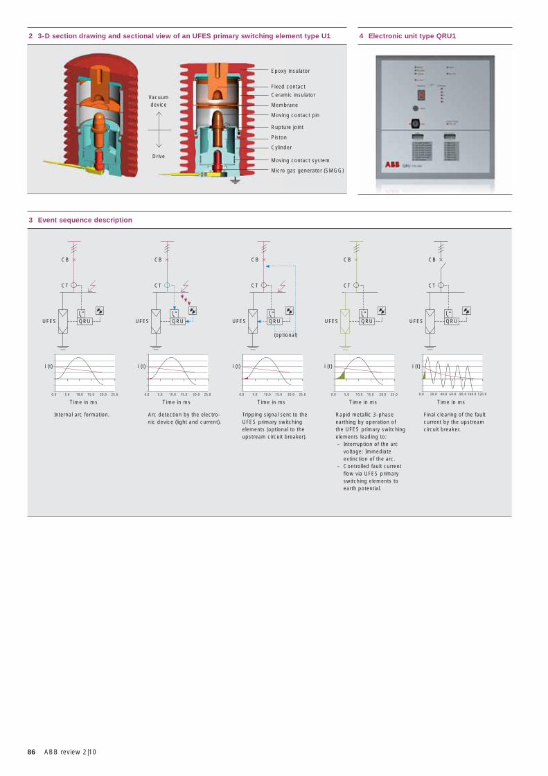
86 ABB review 2|10
3 Event sequence description
Internal arc formation. Arc detection by the electro-nic device (light and current).
Final clearing of the fault current by the upstream circuit breaker.
Tripping signal sent to the UFES primary switching elements (optional to the upstream circuit breaker).
Rapid metallic 3-phase earthing by operation of the UFES primary switching elements leading to:– Interruption of the arc
voltage: Immediate extinction of the arc.
– Controlled fault current flow via UFES primary switching elements to earth potential.
CB
CT
UFES QRUIk“
CB
CT
UFES QRUIk“
CB
CT
UFES QRUIk“
CB
CT
UFES QRUIk“
CB
CT
UFES
(optional)
QRUIk“
Time in ms
0.0 5.0 10.0 15.0 20.0 25.0
i (t)
Time in ms
0.0 5.0 10.0 15.0 20.0 25.0
i (t)
Time in ms
0.0 5.0 10.0 15.0 20.0 25.0
i (t)
Time in ms
0.0 5.0 10.0 15.0 20.0 25.0
i (t)
0.0 20.0 40.0 60.0 80.0 100.0 120.0
i (t)
Time in ms
4 Electronic unit type QRU12 3-D section drawing and sectional view of an UFES primary switching element type U1
Vacuumdevice
Drive
Epoxy insulator
Fixed contact
Ceramic insulator
Membrane
Moving contact pin
Rupture joint
Piston
Cylinder
Moving contact system
Micro gas generator (SMGG)
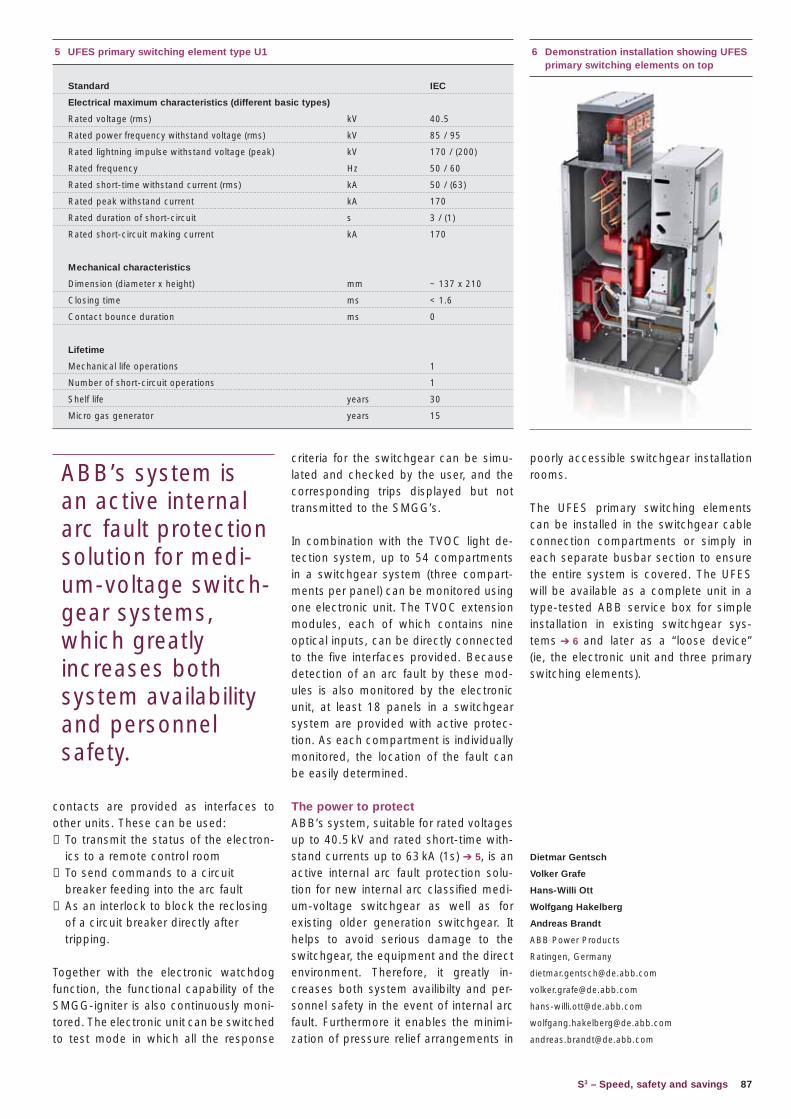
87
criteria for the switchgear can be simu-lated and checked by the user, and the corresponding trips displayed but not transmitted to the SMGG’s.
In combination with the TVOC light de-tection system, up to 54 compartments in a switchgear system (three compart-ments per panel) can be monitored using one electronic unit. The TVOC extension modules, each of which contains nine optical inputs, can be directly connected to the five interfaces provided. Because detection of an arc fault by these mod-ules is also monitored by the electronic unit, at least 18 panels in a switchgear system are provided with active protec-tion. As each compartment is individually monitored, the location of the fault can be easily determined.
The power to protectABB’s system, suitable for rated voltages up to 40.5 kV and rated short-time with-stand currents up to 63 kA (1s) ➔ 5, is an active internal arc fault protection solu-tion for new internal arc classified medi-um-voltage switchgear as well as for existing older generation switchgear. It helps to avoid serious damage to the switchgear, the equipment and the direct environment. Therefore, it greatly in-creases both system availibilty and per-sonnel safety in the event of internal arc fault. Furthermore it enables the minimi-zation of pressure relief arrangements in
S3 – Speed, safety and savings
5 UFES primary switching element type U1
Standard IEC
Electrical maximum characteristics (different basic types)
Rated voltage (rms) kV 40.5
Rated power frequency withstand voltage (rms) kV 85 / 95
Rated lightning impulse withstand voltage (peak) kV 170 / (200)
Rated frequency Hz 50 / 60
Rated short-time withstand current (rms) kA 50 / (63)
Rated peak withstand current kA 170
Rated duration of short-circuit s 3 / (1)
Rated short-circuit making current kA 170
Mechanical characteristics
Dimension (diameter x height) mm ~ 137 x 210
Closing time ms < 1.6
Contact bounce duration ms 0
Lifetime
Mechanical life operations 1
Number of short-circuit operations 1
Shelf life years 30
Micro gas generator years 15
poorly accessible switchgear installation rooms. The UFES primary switching elements can be installed in the switchgear cable connection compartments or simply in each separate busbar section to ensure the entire system is covered. The UFES will be available as a complete unit in a type-tested ABB service box for simple installation in existing switchgear sys-tems ➔ 6 and later as a “loose device” (ie, the electronic unit and three primary switching elements).
Dietmar Gentsch
Volker Grafe
Hans-Willi Ott
Wolfgang Hakelberg
Andreas Brandt
ABB Power Products
Ratingen, Germany
6 Demonstration installation showing UFES primary switching elements on top
contacts are provided as interfaces to other units. These can be used:− To transmit the status of the electron-
ics to a remote control room− To send commands to a circuit
breaker feeding into the arc fault− As an interlock to block the reclosing
of a circuit breaker directly after tripping.
Together with the electronic watchdog function, the functional capability of the SMGG-igniter is also continuously moni-tored. The electronic unit can be switched to test mode in which all the response
ABB’s system is an active internal arc fault protection solution for medi-um-voltage switch-gear systems, which greatly increases both system availability and personnel safety.
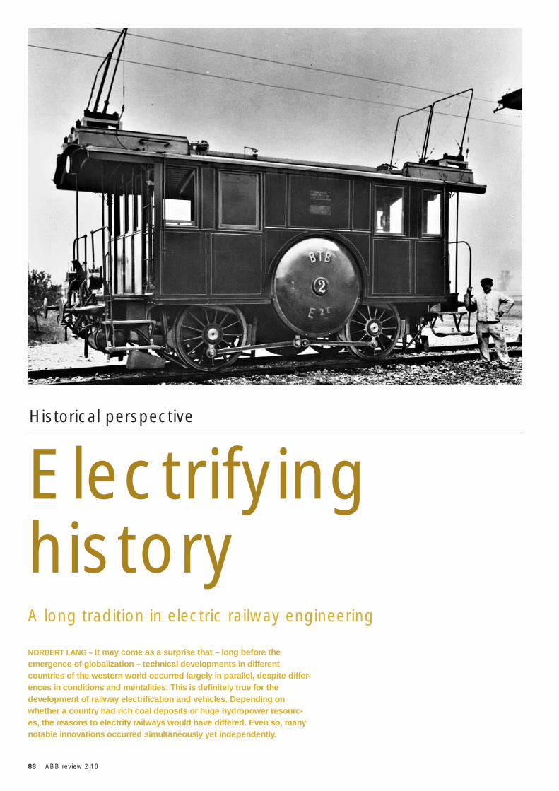
88 ABB review 2|10
NORBERT LANG – It may come as a surprise that – long before the emergence of globalization – technical developments in different countries of the western world occurred largely in parallel, despite differ-ences in conditions and mentalities. This is defi nitely true for the development of railway electrifi cation and vehicles. Depending on whether a country had rich coal deposits or huge hydropower resourc-es, the reasons to electrify railways would have differed. Even so, many notable innovations occurred simultaneously yet independently.
A long tradition in electric railway engineering
Electrifying history
Historical perspective
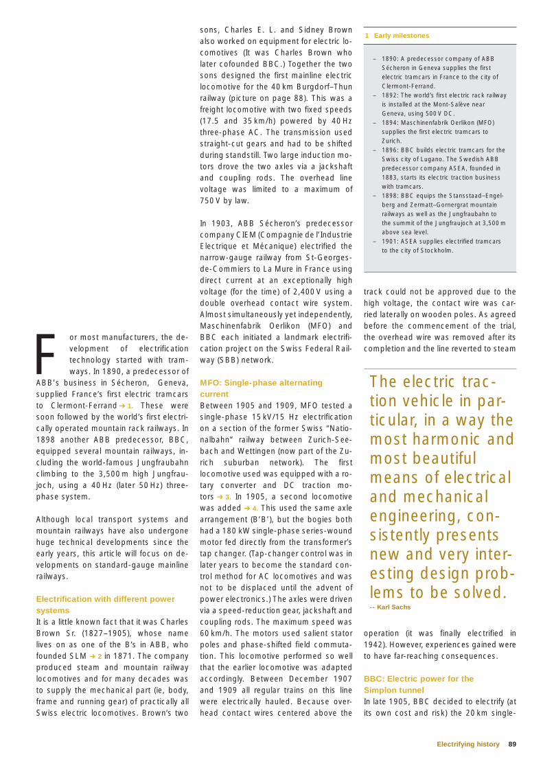
89Electrifying history
track could not be approved due to the high voltage, the contact wire was car-ried laterally on wooden poles. As agreed before the commencement of the trial, the overhead wire was removed after its completion and the line reverted to steam
operation (it was finally electrified in 1942). However, experiences gained were to have far-reaching consequences.
BBC: Electric power for the Simplon tunnelIn late 1905, BBC decided to electrify (at its own cost and risk) the 20 km single-
sons, Charles E. L. and Sidney Brown also worked on equipment for electric lo-comotives (It was Charles Brown who later cofounded BBC.) Together the two sons designed the first mainline electric locomotive for the 40 km Burgdorf–Thun railway (picture on page 88). This was a freight locomotive with two fixed speeds (17.5 and 35 km/h) powered by 40 Hz three-phase AC. The transmission used straight-cut gears and had to be shifted during standstill. Two large induction mo-tors drove the two axles via a jackshaft and coupling rods. The overhead line voltage was limited to a maximum of 750 V by law.
In 1903, ABB Sécheron’s predecessor company CIEM (Compagnie de l’Industrie Electrique et Mécanique) electrified the narrow-gauge railway from St-Georges-de-Commiers to La Mure in France using direct current at an exceptionally high voltage (for the time) of 2,400 V using a double overhead contact wire system. Almost simultaneously yet independently, Maschinenfabrik Oerlikon (MFO) and BBC each initiated a landmark electrifi-cation project on the Swiss Federal Rail-way (SBB) network.
MFO: Single-phase alternating currentBetween 1905 and 1909, MFO tested a single-phase 15 kV/15 Hz electrification on a section of the former Swiss “Natio-nalbahn” railway between Zurich-See-bach and Wettingen (now part of the Zu-rich suburban network). The first locomotive used was equipped with a ro-tary converter and DC traction mo-tors ➔ 3. In 1905, a second locomotive was added ➔ 4. This used the same axle arrangement (B’B’), but the bogies both had a 180 kW single-phase series-wound motor fed directly from the transformer’s tap changer. (Tap-changer control was in later years to become the standard con-trol method for AC locomotives and was not to be displaced until the advent of power electronics.) The axles were driven via a speed-reduction gear, jackshaft and coupling rods. The maximum speed was 60 km/h. The motors used salient stator poles and phase-shifted field commuta-tion. This locomotive performed so well that the earlier locomotive was adapted accordingly. Between December 1907 and 1909 all regular trains on this line were electrically hauled. Because over-head contact wires centered above the
F or most manufacturers, the de-velopment of electrification technology started with tram-ways. In 1890, a predecessor of
ABB's business in Sécheron, Geneva, supplied France’s first electric tramcars to Clermont-Ferrand ➔ 1. These were soon followed by the world’s first electri-cally operated mountain rack railways. In 1898 another ABB predecessor, BBC, equipped several mountain railways, in-cluding the world-famous Jungfraubahn climbing to the 3,500 m high Jungfrau-joch, using a 40 Hz (later 50 Hz) three-phase system.
Although local transport systems and mountain railways have also undergone huge technical developments since the early years, this article will focus on de-velopments on standard-gauge mainline railways.
Electrification with different power systemsIt is a little known fact that it was Charles Brown Sr. (1827–1905), whose name lives on as one of the B’s in ABB, who founded SLM ➔ 2 in 1871. The company produced steam and mountain railway locomotives and for many decades was to supply the mechanical part (ie, body, frame and running gear) of practically all Swiss electric locomotives. Brown’s two
1 Early milestones
– 1890: A predecessor company of ABB Sécheron in Geneva supplies the first electric tramcars in France to the city of Clermont-Ferrand.
– 1892: The world’s first electric rack railway is installed at the Mont-Salève near Geneva, using 500 V DC.
– 1894: Maschinenfabrik Oerlikon (MFO) supplies the first electric tramcars to Zurich.
– 1896: BBC builds electric tramcars for the Swiss city of Lugano. The Swedish ABB predecessor company ASEA, founded in 1883, starts its electric traction business with tramcars.
– 1898: BBC equips the Stansstaad–Engel-berg and Zermatt–Gornergrat mountain railways as well as the Jungfraubahn to the summit of the Jungfraujoch at 3,500 m above sea level.
– 1901: ASEA supplies electrified tramcars to the city of Stockholm.
The electric trac-tion vehicle in par-ticular, in a way the most harmonic and most beautiful means of electrical and mechanical engineering, con-sistently presents new and very inter-esting design prob-lems to be solved.-- Karl Sachs
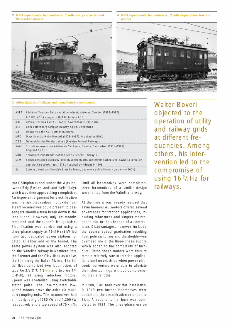
90 ABB review 2|10
Until all locomotives were completed, three locomotives of a similar design were rented from the Valtelina railway.
At the time it was already realized that asynchronous AC motors offered several advantages for traction applications, in-cluding robustness and simpler mainte-nance due to the absence of a commu-tator. Disadvantages, however, included the coarse speed graduation resulting from pole switching and the double-wire overhead line of the three-phase supply, which added to the complexity of turn-outs. Three-phase motors were thus to remain relatively rare in traction applica-tions until recent times when power elec-tronic converters were able to alleviate their shortcomings without compromis-ing their strengths.
In 1908, SBB took over this installation. In 1919 two further locomotives were added and the electrification extended to Sion. A second tunnel bore was com-pleted in 1921. The three-phase era on
track Simplon tunnel under the Alps be-tween Brig (Switzerland) and Iselle (Italy), which was then approaching completion. An important argument for electrification was the risk that carbon monoxide from steam locomotives could present to pas-sengers should a train break down in the long tunnel. However, only six months remained until the tunnel’s inauguration. Electrification was carried out using a three-phase supply at 16 2/3 Hz / 3 kV fed from two dedicated power stations lo-cated at either end of the tunnel. The same power system was also adopted on the Valtelina railway in Northern Italy, the Brenner and the Giovi lines as well as the line along the Italian Riviera. The ini-tial fleet comprised two locomotives of type Ae 3/5 (1’C 1’) ➔ 5 and two Ae 4/4 (0-D-0), all using induction motors. Speed was controlled using switchable stator poles. The low-mounted low-speed motors drove the axles via multi-part coupling rods. The locomotives had an hourly rating of 780 kW and 1,200 kW respectively and a top speed of 75 km/h.
3 MFO experimental locomotive no. 1 with rotary converter and DC traction motors
4 MFO experimental locomotive no. 2 with single-phase traction motors
2 Abbreviations of railway and manufacturing companies
ASEA Allmänna Svenska Elektriska Aktiebolaget, Västeras, Sweden (1983–1987).
In 1988, ASEA merged with BBC to form ABB.
BBC Brown, Boveri & Cie. AG, Baden, Switzerland (1891–1987)
BLS Bern-Lötschberg-Simplon Railway, Spiez, Switzerland
DB Deutsche Bahn AG (German Railways)
MFO Maschinenfabrik Oerlikon AG (1876–1967). Acquired by BBC.
ÖBB Österreichische Bundesbahnen (Austrian Federal Railways)
SAAS Société Anonyme des Ateliers de Sécheron, Geneva, Switzerland (1918–1969). Acquired by BBC.
SBB Schweizerische Bundesbahnen (Swiss Federal Railways)
SLM Schweizerische Lokomotiv- und Maschinenfabrik, Winterthur, Switzerland (Swiss Locomotive
and Machine Works, est. 1871). Acquired by Adtranz in 1998.
SJ Statens Järnvägar (Swedish State Railways, became a public limited company in 2001)
Walter Boveri objected to the operation of utility and railway grids at different fre-quencies. Among others, his inter-vention led to the compromise of using 16 2/3 Hz for railways.
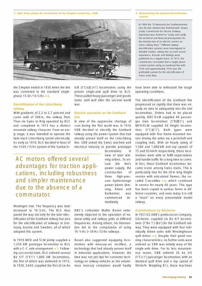
91Electrifying history
have been able to withstand the tough operating conditions.
The electrification of the Gotthard line progressed so rapidly that there was vir-tually no time to adequately test the trial locomotives. Orders had to be placed quickly. BBC/SLM supplied 40 passen-ger train locomotives (1’B)(B1’), and MFO/SLM supplied 50 freight locomo-tives (1’C)(C1’). Both types were equipped with four frame-mounted mo-tors driving the axles via a jackshaft and coupling rods. With an hourly rating of 1,500 and 1,800 kW and top speeds of 75 and 65 km/h respectively, these loco-motives were able to fulfill expectations and handle traffic for a long time to come. In fact, these Gotthard locomotives be-came iconic among Swiss trains. This is particularly true for the 20 m long freight version with articulated frames, the so-called Crocodiles ➔ 8, which continued in service for nearly 60 years. This type has been copied in various forms in dif-ferent countries, and even today it is still a “must” on every presentable model railway.
Contributions by SécheronIn 1921/22 ABB’s predecessor company, Sécheron, supplied six Be 4/7 locomo-tives (1’Bo 1’) (Bo’) for the Gotthard rail-way. They were equipped with four indi-vidually driven axles with Westinghouse quill drives ➔ 9. Despite their good run-ning characteristics, no further units were ordered as SBB was initially wary of the single-axle drive. For its less mountain-ous routes, SBB ordered 26 Ae 3/5 (1’Co 1’) passenger locomotives with an identical quill drive and a top speed of 90 km/h. Weighing 81 t, these machines
6/8 (1’Co)(Co1’) locomotives using the proven single-axle quill drive to BLS. These pulled heavy passenger and goods trains until well after the second world war.
Electric operation on the Gotthard lineIn view of the oppressive shortage of coal during the first world war, in 1916 SBB decided to electrify the Gotthard railway using the power system that had already proven itself on the Lötschberg line. SBB asked the Swiss machine and electrical industry to provide prototype
locomotives in view of later win-ning orders. To en-sure the line’s power supply, the construction of three high-pres-sure hydrostorage power plants (Am-steg, Ritom and Barberine) was commenced im-mediately.
BBC’s cofounder Walter Boveri vehe-mently objected to the operation of na-tional utility and railway grids at different frequencies. Among others, his interven-tion led to the compromise of using 16 2/3 Hz (= 50 Hz / 3) for railways.
Boveri also suggested equipping loco-motives with mercury-arc rectifiers, a technology that had already proven itself in industrial applications. However, the time was not yet ripe for converter tech-nology on railway vehicles as the volumi-nous mercury containers would hardly
the Simplon ended in 1930 when the line was converted to the standard single-phase 15 kV / 16 2/3 Hz ➔ 6.
Electrification of the Lötschberg railwayWith gradients of 2.2 to 2.7 percent and curve radii of 300 m, the railway from Thun via Spiez to Brig operated by BLS and completed in 1913 has a distinct mountain railway character. From an ear-ly stage, it was intended to operate the twin-track Lötschberg tunnel electrically. As early as 1910, BLS decided in favor of the 15 kV / 15 Hz system of the Seebach–
Wettingen trial. The frequency was later increased to 16 2/3 Hz. The BLS thus paved the way not only for the later elec-trification of the Gotthard railway but also for the electrification of railways in Ger-many, Austria and Sweden, all of which adopted this system.
In 1910 MFO and SLM jointly supplied a 1,250 kW prototype locomotive to BLS with a C-C axle arrangement ➔ 7. Follow-ing successful trials, BLS ordered several Be 5/7 (1’E1’) 1,800 kW locomotives, the first of which was delivered in 1913. In 1930, SAAS supplied the first of six Ae
5 BBC three-phase AC locomotive of the Simplon tunnel line, 1906 6 Determining the optimal electrification system
In 1904 the “Schweizerische Studienkommis-sion für den elektrischen Bahnbetrieb” (Swiss Study Commission for Electric Railway Operation) was formed to “study and clarify the technical and financial prerequisites for the introduction of an electric service on Swiss railway lines.” Different railway electrification systems were investigated in detailed studies, taking into account recent experience. Results and findings were published on a regular basis. In 1912, the commission concluded that a single-phase current system using an overhead line with 15 kV and approximately 15 Hz was the preferable system for the electrification of Swiss main lines.
AC motors offered several advantages for traction appli-cations, including robustness and simpler maintenance due to the absence of a commutator.
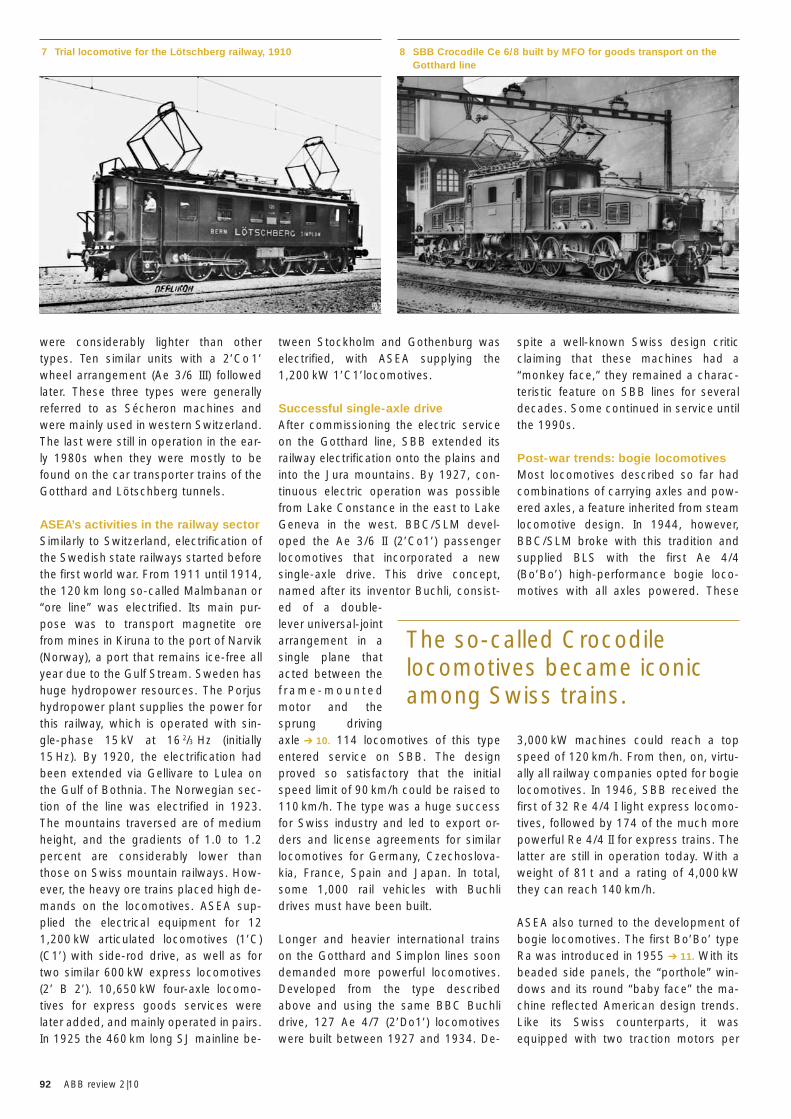
92 ABB review 2|10
spite a well-known Swiss design critic claiming that these machines had a “monkey face,” they remained a charac-teristic feature on SBB lines for several decades. Some continued in service until the 1990s.
Post-war trends: bogie locomotivesMost locomotives described so far had combinations of carrying axles and pow-ered axles, a feature inherited from steam locomotive design. In 1944, however, BBC/SLM broke with this tradition and supplied BLS with the first Ae 4/4 (Bo’Bo’) high-performance bogie loco-motives with all axles powered. These
3,000 kW machines could reach a top speed of 120 km/h. From then, on, virtu-ally all railway companies opted for bogie locomotives. In 1946, SBB received the first of 32 Re 4/4 I light express locomo-tives, followed by 174 of the much more powerful Re 4/4 II for express trains. The latter are still in operation today. With a weight of 81 t and a rating of 4,000 kW they can reach 140 km/h.
ASEA also turned to the development of bogie locomotives. The first Bo’Bo’ type Ra was introduced in 1955 ➔ 11. With its beaded side panels, the “porthole” win-dows and its round “baby face” the ma-chine reflected American design trends. Like its Swiss counterparts, it was equipped with two traction motors per
tween Stockholm and Gothenburg was electrified, with ASEA supplying the 1,200 kW 1’C1’locomotives.
Successful single-axle driveAfter commissioning the electric service on the Gotthard line, SBB extended its railway electrification onto the plains and into the Jura mountains. By 1927, con-tinuous electric operation was possible from Lake Constance in the east to Lake Geneva in the west. BBC/SLM devel-oped the Ae 3/6 II (2’Co1’) passenger locomotives that incorporated a new single-axle drive. This drive concept, named after its inventor Buchli, consist-ed of a double- lever universal-joint arrangement in a single plane that acted between the f r a m e - m o u n t e d motor and the sprung driving axle ➔ 10. 114 locomotives of this type entered service on SBB. The design proved so satisfactory that the initial speed limit of 90 km/h could be raised to 110 km/h. The type was a huge success for Swiss industry and led to export or-ders and license agreements for similar locomotives for Germany, Czechoslova-kia, France, Spain and Japan. In total, some 1,000 rail vehicles with Buchli drives must have been built.
Longer and heavier international trains on the Gotthard and Simplon lines soon demanded more powerful locomotives. Developed from the type described above and using the same BBC Buchli drive, 127 Ae 4/7 (2’Do1’) locomotives were built between 1927 and 1934. De-
were considerably lighter than other types. Ten similar units with a 2’Co 1’ wheel arrangement (Ae 3/6 III) followed later. These three types were generally referred to as Sécheron machines and were mainly used in western Switzerland. The last were still in operation in the ear-ly 1980s when they were mostly to be found on the car transporter trains of the Gotthard and Lötschberg tunnels.
ASEA’s activities in the railway sectorSimilarly to Switzerland, electrification of the Swedish state railways started before the first world war. From 1911 until 1914, the 120 km long so-called Malmbanan or “ore line” was electrified. Its main pur-pose was to transport magnetite ore from mines in Kiruna to the port of Narvik (Norway), a port that remains ice-free all year due to the Gulf Stream. Sweden has huge hydropower resources. The Porjus hydropower plant supplies the power for this railway, which is operated with sin-gle-phase 15 kV at 16 2/3 Hz (initially 15 Hz). By 1920, the electrification had been extended via Gellivare to Lulea on the Gulf of Bothnia. The Norwegian sec-tion of the line was electrified in 1923. The mountains traversed are of medium height, and the gradients of 1.0 to 1.2 percent are considerably lower than those on Swiss mountain railways. How-ever, the heavy ore trains placed high de-mands on the locomotives. ASEA sup-plied the electrical equipment for 12 1,200 kW articulated locomotives (1’C)(C1’) with side-rod drive, as well as for two similar 600 kW express locomotives (2’ B 2’). 10,650 kW four-axle locomo-tives for express goods services were later added, and mainly operated in pairs. In 1925 the 460 km long SJ mainline be-
7 Trial locomotive for the Lötschberg railway, 1910 8 SBB Crocodile Ce 6/8 built by MFO for goods transport on the Gotthard line
The so-called Crocodile locomotives became iconic among Swiss trains.
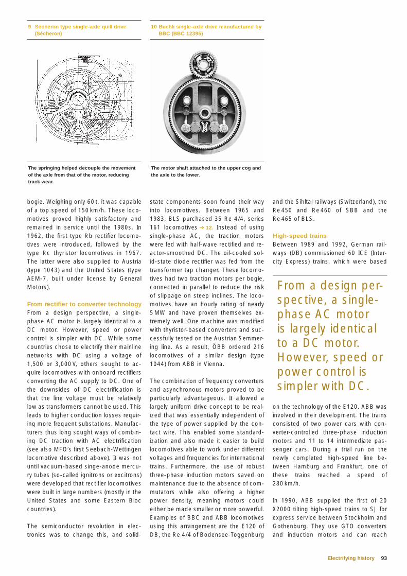
93Electrifying history
and the Sihltal railways (Switzerland), the Re 450 and Re 460 of SBB and the Re 465 of BLS.
High-speed trainsBetween 1989 and 1992, German rail-ways (DB) commissioned 60 ICE (Inter-city Express) trains, which were based
on the technology of the E120. ABB was involved in their development. The trains consisted of two power cars with con-verter-controlled three-phase induction motors and 11 to 14 intermediate pas-senger cars. During a trial run on the newly completed high-speed line be-tween Hamburg and Frankfurt, one of these trains reached a speed of 280 km/h.
In 1990, ABB supplied the first of 20 X2000 tilting high-speed trains to SJ for express service between Stockholm and Gothenburg. They use GTO converters and induction motors and can reach
state components soon found their way into locomotives. Between 1965 and 1983, BLS purchased 35 Re 4/4, series 161 locomotives ➔ 12. Instead of using single-phase AC, the traction motors were fed with half-wave rectified and re-actor-smoothed DC. The oil-cooled sol-id-state diode rectifier was fed from the transformer tap changer. These locomo-tives had two traction motors per bogie, connected in parallel to reduce the risk of slippage on steep inclines. The loco-motives have an hourly rating of nearly 5 MW and have proven themselves ex-tremely well. One machine was modified with thyristor-based converters and suc-cessfully tested on the Austrian Semmer-ing line. As a result, ÖBB ordered 216 locomotives of a similar design (type 1044) from ABB in Vienna.
The combination of frequency converters and asynchronous motors proved to be particularly advantageous. It allowed a largely uniform drive concept to be real-ized that was essentially independent of the type of power supplied by the con-tact wire. This enabled some standard-ization and also made it easier to build locomotives able to work under different voltages and frequencies for international trains. Furthermore, the use of robust three-phase induction motors saved on maintenance due to the absence of com-mutators while also offering a higher power density, meaning motors could either be made smaller or more powerful. Examples of BBC and ABB locomotives using this arrangement are the E120 of DB, the Re 4/4 of Bodensee-Toggenburg
bogie. Weighing only 60 t, it was capable of a top speed of 150 km/h. These loco-motives proved highly satisfactory and remained in service until the 1980s. In 1962, the first type Rb rectifier locomo-tives were introduced, followed by the type Rc thyristor locomotives in 1967. The latter were also supplied to Austria (type 1043) and the United States (type AEM-7, built under license by General Motors).
From rectifier to converter technologyFrom a design perspective, a single-phase AC motor is largely identical to a DC motor. However, speed or power control is simpler with DC. While some countries chose to electrify their mainline networks with DC using a voltage of 1,500 or 3,000 V, others sought to ac-quire locomotives with onboard rectifiers converting the AC supply to DC. One of the downsides of DC electrification is that the line voltage must be relatively low as transformers cannot be used. This leads to higher conduction losses requir-ing more frequent substations. Manufac-turers thus long sought ways of combin-ing DC traction with AC electrification (see also MFO’s first Seebach-Wettingen locomotive described above). It was not until vacuum-based singe-anode mercu-ry tubes (so-called ignitrons or excitrons) were developed that rectifier locomotives were built in large numbers (mostly in the United States and some Eastern Bloc countries).
The semiconductor revolution in elec-tronics was to change this, and solid-
9 Sécheron type single-axle quill drive (Sécheron)
10 Buchli single-axle drive manufactured by BBC (BBC 12395)
The motor shaft attached to the upper cog and the axle to the lower.
From a design per-spective, a single-phase AC motor is largely identical to a DC motor. However, speed or power control is simpler with DC.
The springing helped decouple the movement of the axle from that of the motor, reducing track wear.
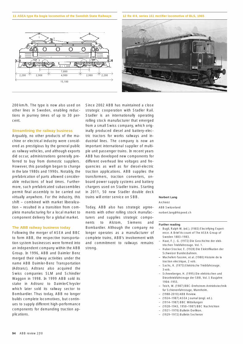
94 ABB review 2|10
Norbert Lang
Archivist
ABB Switzerland
Further reading– Bugli, Ralph W. (ed.). (1983) Electrifying Experi-
ence. A Brief Account of The ASEA Group of Sweden 1883–1983.
– Haut, F. J. G. (1972) Die Geschichte der elek-trischen Triebfahrzeuge. Vol. 1.
– Huber-Stockar, E. (1928) Die Elektrifikation der Schweizer Bundesbahnen.
– Machefert-Tassinn, et al. (1980) Histoire de la traction electrique, 2 vols.
– Sachs, K. (1973) Elektrische Triebfahrzeuge. 3 vols.
– Schneeberger, H. (1995) Die elektrischen und Dieseltriebfahrzeuge der SBB, Vol. I: Baujahre 1904–1955.
– Teich, W. (1987) BBC-Drehstrom-Antriebstechnik fur Schienenfahrzeuge, Mannheim.
– (1988-2010) ABB Review.– (1924–1987) ASEA Journal (engl. ed.).– (1914–1987) BBC Mitteilungen – (1928–1943, 1950–1987) BBC Nachrichten – (1921–1970) Bulletin Oerlikon.– (1929–1972) Bulletin Secheron
Since 2002 ABB has maintained a close strategic cooperation with Stadler Rail. Stadler is an internationally operating rolling stock manufacturer that emerged from a small Swiss company, which orig-inally produced diesel and battery-elec-tric tractors for works railways and in-dustrial lines. The company is now an important international supplier of multi-ple unit passenger trains. In recent years ABB has developed new components for different overhead line voltages and fre-quencies as well as for diesel-electric traction applications. ABB supplies the transformers, traction converters, on-board power supply systems and battery chargers used on Stadler trains. Starting in 2011, 50 new Stadler double deck trains will enter service on SBB.
Today, ABB also has strategic agree-ments with other rolling stock manufac-turers and supplies strategic compo-nents to Alstom, Siemens and Bombardier. Although the company no longer operates as a manufacturer of complete trains, ABB’s involvement with and commitment to railways remains strong.
200 km/h. The type is now also used on other lines in Sweden, enabling reduc-tions in journey times of up to 30 per-cent.
Streamlining the railway businessArguably, no other products of the ma-chine or electrical industry were consid-ered as prestigious by the general public as railway vehicles, and although exports did occur, administrations generally pre-ferred to buy from domestic suppliers. However, this paradigm began to change in the late 1980s and 1990s. Notably, the prefabrication of parts allowed consider-able reductions of lead times. Further-more, such prefabricated subassemblies permit final assembly to be carried out virtually anywhere. For the industry, this shift – combined with market liberaliza-tion – resulted in a transition from com-plete manufacturing for a local market to component delivery for a global market.
The ABB railway business todayFollowing the merger of ASEA and BBC to form ABB, the respective transporta-tion system businesses were formed into an independent company within the ABB Group. In 1996, ABB and Daimler Benz merged their railway activities under the name ABB Daimler-Benz Transportation (Adtranz). Adtranz also acquired the Swiss companies SLM and Schindler Waggon in 1998. In 1999 ABB sold its stake in Adtranz to DaimlerChrysler which later sold its railway sector to Bombardier. Thus today, ABB no longer builds complete locomotives, but contin-ues to supply different high-performance components for demanding traction ap-plications.
12 Re 4/4, series 161 rectifier locomotive of BLS, 196511 ASEA type Ra bogie locomotive of the Swedish State Railways
d = 1,300
2,200 2,2002,900
1 2
3 3
2,9004,900
15,100
7,800
95Preview
Preview 3|10
Green perspectives
ABB has numerous technologies that enable production and processes to become more efficient, both in terms of energy usage and of productivity. The company’s variable-speed drives, for example, permit huge energy savings to be made in com-parison to the more traditional method of using throttling elements to control speed. Not only is less energy input required to do the same work (environmental benefits) but costs are also saved thanks to short pay-back times. Typical applications for such variable-speed drives include fans, pumps, belts and conveyors. They can also be found in more unorthodox situa-tions: for example powering the retractable roof of the Dallas Cowboy’s football stadium.
Variable speed drives are just one application of ABB’s expertise in power electronics. Power electronics permit current and voltage to be modified to virtually any desired waveform and frequency. Issue 3/2010 of ABB Review will look at some of these applications, and also the components at the heart of power electronics: solid state switching devices.
Continuing with the topic of saving energy and boosting productivity, the journal will also look at a building of the future, the latest developments in wind energy and a way to reduce emissions from ship’s engines.
Editorial Board
Peter TerwieschChief Technology OfficerGroup R&D and Technology
Clarissa HallerHead of Corporate Communications
Ron PopperManager of Sustainability Affairs
Axel KuhrHead of Group Account Management
Friedrich PinnekampVice President, Corporate Strategy
Andreas MoglestueChief Editor, ABB [email protected]
PublisherABB Review is published by ABB Group R&D and Technology.
ABB Asea Brown Boveri Ltd.ABB Review/REVCH-8050 ZürichSwitzerland
ABB Review is published four times a year in English, French, German, Spanish, Chinese and Russian. ABB Review is free of charge to those with an interest in ABB’s technology and objectives. For a sub scription, please contact your nearest ABB representative or subscribe online at www.abb.com/abbreview
Partial reprints or reproductions are per mitted subject to full acknowledgement. Complete reprints require the publisher’s written consent.
Publisher and copyright ©2010ABB Asea Brown Boveri Ltd. Zürich/Switzerland
PrinterVorarlberger Verlagsanstalt GmbHAT-6850 Dornbirn/Austria
LayoutDAVILLA Werbeagentur GmbHAT-6900 Bregenz/Austria
DisclaimerThe information contained herein reflects the views of the authors and is for informational purposes only. Readers should not act upon the information contained herein without seeking professional advice. We make publications available with the understanding that the authors are not rendering technical or other professional advice or opinions on specific facts or matters and assume no liability whatsoever in connection with their use. The companies of the ABB Group do not make any warranty or guarantee, or promise, expressed or implied, concerning the content or accuracy of the views expressed herein.
ISSN: 1013-3119
www.abb.com/abbreview

As the world’s leading company for energy and automation technology, ABB plays a vital role in the efficient and safe operation of railway public transportation systems and therefore also the sustainable care of the environment. Our reliable products can be found wherever railway services are set in motion by means of electrical energy, for example with energy-efficient on-board traction power supplies, infrastructure systems and network management solutions. www.abb.com/railway
Powering the railways. Efficient and reliable solutions for sustainable mobility.
INNOTRANSBerlin, 21. – 24. September 2010Halls 2.2 & 26, Stands 207 & 226


![Project Management & Technical Consultancy Services [Transportation, Railways]](https://img.pdfslide.net/doc/110x75/557d0c3ed8b42a8c2f8b5001/project-management-technical-consultancy-services-transportation-railways.jpg)