Embed Size (px)
Citation preview

RA
PP
OR
T
Dansk Gasteknisk Center a/s • Dr. Neergaards Vej 5B • 2970 Hørsholm • Tlf. 2016 9600 • Fax 4516 1199 • www.dgc.dk • [email protected]
Global screening of projects and technologies for Power-to-Gas and Bio-SNG A reference report
Project ReportNovember 2013

Global screening of projects and technologies
for Power-to-Gas and Bio-SNG
A reference report
Henrik Iskov, Niels Bjarne Rasmussen
Danish Gas Technology Centre
Hørsholm 2013

Title : Global screening of projects and technologies for Power-to-Gas and Bio-SNG
Report
Category : Project Report
Author : Henrik Iskov, Niels Bjarne Rasmussen
Date of issue : 08.11.2013
Copyright : Danish Gas Technology Centre
File Number : 739-27; h:\739\27 el_gas projekter\rapport\global_screening_08112013_final.docx
Project Name : Screening, el-gasprojekter
ISBN : 978-87-7795-373-6
Key words : hydrogen, gasification, methane, electrolysis, power-to-gas, bio-SNG
(brint, forgasning, metan, elektrolyse, power-to-gas, bio-SNG)
DGC-report 1
Table of Contents Page
1 Summary ............................................................................................................................... 5
1.1 Bio-SNG .............................................................................................................................. 5
1.2 Electrolysis .......................................................................................................................... 6
2 Introduction ........................................................................................................................... 8
2.1 Objective ............................................................................................................................. 8
2.2 Emphasis ............................................................................................................................. 8
2.3 Implementation and sorting ................................................................................................. 8
3 Austria ................................................................................................................................... 9
3.1 The Güssing gasifier ............................................................................................................ 9
3.2 The Oberwart plant ............................................................................................................ 11
4 The Netherlands .................................................................................................................. 12
4.1 MILENA and OLGA processes ........................................................................................ 12
4.2 The Ameland project ......................................................................................................... 13
4.3 P2G project in Rozenburg ................................................................................................. 15
5 Denmark .............................................................................................................................. 16
5.1 The Vestenskov project ..................................................................................................... 16
5.1.1 The plants .............................................................................................................. 17
5.2 Region Midtjylland (The Central Denmark Region), project “Towards the Methane
Society” ...................................................................................................................................... 18
5.3 Electrochaea ...................................................................................................................... 19
5.4 Biogas upgraded using surplus electricity ......................................................................... 21
5.5 MeGa-stoRE – storage of biogas and wind power on the gas network ............................ 23
5.6 DTU, biogas: Hydrogen directly to a biogas plant ............................................................ 24
5.7 Green Natural Gas ............................................................................................................. 25
5.8 Carbona - Skive ................................................................................................................. 27
5.9 The Pyroneer gasifier ........................................................................................................ 28
5.10 Viking gasifier, Weiss ................................................................................................... 29
5.11 Firgas Alternating Gasifier, Ammongas and Vølund .................................................... 30
6 Sweden ................................................................................................................................ 33
6.1 The Chalmers gasifier ....................................................................................................... 33
6.2 The GOBIGAS project ...................................................................................................... 34
6.3 The E.ON project, Bio2G .................................................................................................. 37

DGC-report 2
6.4 CORTUS-WoodRoll three-stage gasification ................................................................... 38
7 Germany .............................................................................................................................. 40
7.1 Power to Gas (P2G), Werlte biogas plant ......................................................................... 40
7.2 Audi project e-gas ............................................................................................................. 41
7.2.1 Main data /22/ ........................................................................................................ 42
7.2.2 Time schedule /22/ ................................................................................................ 42
7.2.3 Project partners ...................................................................................................... 43
7.3 Kombikraftwerk 1 ............................................................................................................. 43
7.3.1 Project partners ...................................................................................................... 44
7.4 Kombikraftwerk 2 ............................................................................................................. 44
7.5 Enertrag Hybridkraftwerk ................................................................................................. 45
7.6 Solarfuel and Juwi project P2G Morbach ......................................................................... 46
7.6.1 Time schedule ....................................................................................................... 47
7.7 Project RH2-WKA ............................................................................................................ 47
7.8 E.ON Falkenhagen electrolysis and hydrogen in gas grids ............................................... 48
7.9 Power-to-gas plant Hamburg, Reitbrook .......................................................................... 50
7.10 RWE demo, Ibbenbüren ................................................................................................ 51
7.11 P2G demo Thüga Group ............................................................................................... 52
7.12 P2G by Microbenergy: Eucolino at Schwandorf .......................................................... 53
7.13 DVGW-EBI research project: Storage of electrical energy from regenerative energy
sources in the natural gas grid – H2O electrolysis and synthesis of gas components ................ 54
7.13.1 Project partners .................................................................................................. 54
7.14 DVGW-GUT research project: Development of modular concepts for generation,
storage and injection of hydrogen into the natural gas grid ....................................................... 55
7.14.1 Project partners .................................................................................................. 55
7.15 Absorption Enhanced Reforming at ZSW .................................................................... 56
7.16 The Blue Tower concept ............................................................................................... 58
7.17 Heat Pipe technology .................................................................................................... 60
7.18 Super critical gasification of wet organic waste at the Karlsruhe Institute of
Technology (KIT) ...................................................................................................................... 62
8 Switzerland ......................................................................................................................... 65
8.1 Paul Scherrer Institut ......................................................................................................... 65
9 France .................................................................................................................................. 66
9.1 GAYA project ................................................................................................................... 66
9.2 Cyrano-1-project: Wind farms connected to hydrogen grid ............................................. 67
DGC-report 3
9.2.1 Project partners ...................................................................................................... 68
9.3 GRHYD project ................................................................................................................. 68
9.3.1 Project partners ...................................................................................................... 69
9.4 Myrte (Corsica) ................................................................................................................. 69
9.5 Minerve ............................................................................................................................. 70
9.6 ElectroHgena ..................................................................................................................... 72
10 Italy ..................................................................................................................................... 73
10.1 Ingrid, FCH JU project .................................................................................................. 73
11 Spain ................................................................................................................................... 75
11.1 Sotavento ....................................................................................................................... 75
11.1.1 Results of the project ......................................................................................... 76
12 Great Britain ....................................................................................................................... 77
13 Finland ................................................................................................................................ 78
13.1 VTT Technical Research Centre of Finland ................................................................. 78
14 USA .................................................................................................................................... 79
14.1 Electrolysis projects based on RE ................................................................................. 79
14.2 The Lurgi process – the Great Plains Synfuels Plant .................................................... 79
14.3 The SilvaGas plant ........................................................................................................ 80
14.4 GreatPoint Energy ......................................................................................................... 81
14.5 Rentech-ClearFuels Biomass Gasification Process ....................................................... 83
15 Japan ................................................................................................................................... 85
16 Argentina ............................................................................................................................ 86
16.1 Hychico ......................................................................................................................... 86
17 New Zealand ....................................................................................................................... 88
17.1 University of Canterbury ............................................................................................... 88
18 Gas cleaning and conditioning ............................................................................................ 89
19 Methanation technologies ................................................................................................... 91
19.1 Haldor Topsoe’s TREMP process ................................................................................. 91
19.2 Methanation at PSI ........................................................................................................ 93
19.3 Methanation at ZSW ..................................................................................................... 94

DGC-report 4
19.4 The agnion methanation reactor (AMR) ....................................................................... 94
19.5 Bio-methanation ............................................................................................................ 95
20 Possible small-scale demonstration projects ....................................................................... 98
20.1 Demonstration project for gasification in Denmark ...................................................... 98
20.2 Demonstration of DTU’s hydrogen injection into biogas plants .................................. 99
21 Abbreviations and glossary ............................................................................................... 100
22 References ......................................................................................................................... 102
Appendix
Appendix 1 Project description

DGC-report 5
1 Summary
At the request of Energinet.dk Danish Gas Technology Centre (DGC) has
updated the previous (December 2011) global screening of projects where
gas is produced for the grid and projects integrating electricity and gas. As
the screening did not include projects with ordinary biogas plants with up-
grading to natural gas quality the identified relevant projects are divided into
two main groups: Bio-SNG plants and plants with electrolysis.
1.1 Bio-SNG
Only gasification plants for production of bio-SNG will be relevant for the
integrated planning of electricity and gas systems in Denmark. Gasification
plants for CHP may be relevant for electricity and heating systems, but not
for electricity/gas. State-of-the-art for bio-SNG from gasification is the indi-
rect gasification method (allothermal), where combustion takes place out-
side the gasification reactor and with steam-blown gasification.
The direct gasification methods, where combustion takes place in the gasifi-
cation reactor, are mostly air-blown. This means that N2 is present in the
producer gas, which is undesired for bio-SNG. It is possible, though, to use
the direct methods with oxygen-/steam-blown gasification, but the efficien-
cy will be lower, and it is necessary to establish on-site oxygen production.
The indirect (allothermal) gasification methods seem to be best developed in
Austria, the Netherlands and Sweden. The Güssing plant in Austria and the
plant at Chalmers in Sweden will be used as reference for the GOBIGAS
project in Sweden, the first commercial bio-SNG plant world-wide.
The MILENA plant at ECN in the Netherlands is used as reference for the
first Dutch bio-SNG plant, which is planned to be built in cooperation with
the Dutch HVC-Group in Alkmaar.
GreatPoint Energy in the USA uses a technology that seems to be very suit-
ed for bio-SNG. However, the company is now cooperating with a large
coal producer and is now focussing on coal-based SNG in the USA and
China.

DGC-report 6
The direct gasification methods are used all over the world, but especially
Finnish Carbona and Danish Pyroneer seem to be technologies that, over
time, may become relevant for bio-SNG. The Carbona technology is used in
Skive achieving experience with tar cleaning in collaboration with Haldor
Topsøe. Pyroneer is owned by DONG Energy, and like the Carbona tech-
nology Pyroneer can be modified for oxygen-/steam-blown technologies for
the purpose of bio-SNG.
E.ON in Sweden is contemplating to use the Carbona technology for a 200
MW plant in the south of Sweden for production of bio-SNG.
1.2 Electrolysis
As the screening did not include industrial utilisation of electrolysis plants
and plants for refuelling of hydrogen vehicles, most of the plants in connec-
tion with energy supply are stand-alone plants. I.e. hydrogen acts as storage
for a fluctuating electricity supply based on solar and wind. Demonstration
plants of this type are found all over the world. The typical plant size is 5-
100 kWe.
Electrolysis plants used in systems connecting the electricity and natural gas
systems have only been realised as demonstration plants in Germany and
France during the last couple of years. More are on their way, though, in
Denmark, Germany, France, The Netherlands and Italy. The main principles
of this kind of plants are that surplus electricity is converted to hydrogen via
an electrolyser, and
either
a) that hydrogen from an electrolyser with a CO2 source (typically from a
biogas plant) is fed to a methanation unit prior to feeding the gas to the gas
grid. The report describes several varieties.
or
b) that hydrogen from an electrolyser is fed directly to the natural gas grid.
In some countries 5 % vol. hydrogen is already permitted in the gas grid,
and some say that e.g. 15 % vol. could be permitted without considerable
modifications of the gas consuming appliances. (DGC is not of this opinion
– especially as it is evident that electrolysis plants will be given the task of
DGC-report 7
acting as “peak shaving” resulting in very fluctuating hydrogen content in
the grid.)
or
c) that hydrogen from an electrolyser is stored and converted to electrici-
ty/heat via a CHP unit (fuel cell plant or gas engine), when electricity is
needed. Biogas via storage may be included in a variable share.
The reason that Denmark and Germany are following this path is that in
these countries a heavy expansion of renewable energy plants is on the
agenda. This requires increased balancing of the system, and the interest in
energy storage is thus sky-high.

DGC-report 8
2 Introduction
2.1 Objective
According to Energinet.dk’s project description (Appendix 1) and supple-
mentary conversations the objective is to acquire an up-to-date overview
over completed and on-going projects (test, development, demonstration)
that integrate electricity and gas.
2.2 Emphasis
a) Projects including e.g. electrolysis, where gas is going to be stored in the
natural gas grid, either immediately or in the long run.
b) Projects including thermal gasification and methanation to achieve gas
grid quality (SNG plants).
c) Combined projects with several different technologies, such as electrol-
ysis, CHP, biogas. The crucial issue is that gas (grid) storage is included.
2.3 Implementation and sorting
The screening is carried out country by country.
For countries not mentioned no relevant projects was identified.
The following template has been used, if possible:
a) Description of principles
b) Diagram
c) Main data
d) Status and progress
e) Contact data for key persons
“Gas cleaning and conditioning” as well as “Methanation” have been added
as separate chapters in the report.

DGC-report 9
3 Austria
3.1 The Güssing gasifier
The most enhanced indirect gasification system for biomass seems to be the
Güssing gasification system, which is based on fluid bed technology and
steam. It was primarily developed at VUT (Vienna University of Technolo-
gy). It is called the FICFB-technology (Fast Internal Circulating Fluid Bed).
Figure 3.1 shows schematically the indirect gasification method. The reac-
tors consist of two fluid beds (dual fluid bed) – one for gasification and one
for combustion.
Figure 3.1 Diagram of indirect gasification principle /8/
Gasification is to the left where steam is fed from the bottom and biomass
from the left. The heat for this process is added in the form of hot particles,
such as sand, dolomite etc. and then heated in the combustion section. The
producer gases exit from the top of the gasifier to the left, and at the bottom
sand and degasified char particles are transported to the combustion reactor.
In the combustion reactor air is fed at the bottom and char particles burn in
the fluid bed and heat the sand, which is led to the gasifier. Often the circu-
lating mass flow rate of this heat carrier is much larger than that of the bio-
mass. Based on the lower calorific value of the biomass this method can
achieve an efficiency up to 70 % from biomass to SNG.
When the producer gas is cleaned for particles, tar and other components, it
can be converted into bio-SNG.

DGC-report 10
In Güssing an 8 MW gasifier plant is in operation. It has been connected to
a 1 MW methanation unit, which has demonstrated production of synthetic
natural gas (SNG). The project was financed by EU, FP6 Project BIO-SNG,
where 9 different European countries participated. Figure 3.2 shows a dia-
gram of the Güssing gasifier.
Figure 3.2 Diagram of the FICFB Güssing plant /8/
The gasifier in this system is a bubbling fluid bed, while the combustion
reactor is a circulation fluid bed with a riser where the char particles and bed
material are lifted by means of a high upward gas velocity. The producer gas
from this process has a relatively low content of tar.
The gasification products are used in boilers, for CHP and for demonstration
of fuel production (incl. bio-SNG). For demonstration purposes a compres-
sor unit was installed and natural gas vehicles have been fuelled with bio-
SNG from wood gasification.
Contact
www.repotec.at

DGC-report 11
3.2 The Oberwart plant
The CHP plant in Oberwart produces gasification gas to be used directly in
an engine for the production of electricity and heat. The fuel input is approx.
8.7 MW. In the summer, where the need for heat is small, an ORC process
(Organic Rankine Cycle) is used to increase electricity production. The elec-
trical efficiency is approx. 27 % and the overall efficiency is approx. 64 %.
Figure 3.3 Schematic view of the Oberwart plant /9/
The Austrian plants (Güssing and Oberwart) are semi-commercial: They
receive continuous subsidies for participation in research projects in addi-
tion to the revenue of electricity and heat production.
Repotec is an Austrian company with only few employees (< 10). The com-
pany performs basic engineering for plants for biomass gasification. Re-
potec was in charge of the Güssing plant and performed basic engineering of
the Oberwart plant, which was basically a copy of the Güssing plant.
Contact
Herman Hoffbauer, TÜV

DGC-report 12
4 The Netherlands
4.1 MILENA and OLGA processes
Another interesting technology is the MILENA technology that ECN (Ener-
gy research Centre of the Netherlands) has developed. It is similar to the
Güssing technology, but was developed specially for bio-SNG production
and is intended to be used in combination with another process developed
by ECN - the OLGA process. The OLGA process is a method to efficiently
remove tar from the producer gas. The combination MILENA-OLGA is
reported to give 70 % biomass -> bio-SNG conversion.
An 800 kW plant is in operation at ECN in Petten, The Netherlands. The
next phase includes a 10 MW plant, which, however, will not be located at
ECN. It will be built together with the Dutch HVC Group at Alkmaar in the
Netherlands.
The OLGA process is a gas cleaning process to remove tar from producer
gases. The energy of the gas cleaning process is utilised in the gasification
process. The Dutch company Dahlman (www.dahlman.nl) holds the rights
to the process. The OLGA technology was demonstrated at a 4 MW plant in
Moisannes, France.
ECN’s gasification process is an indirect fluid bed process. Steam and air is
added to the gasification process, and the bed material is then heated in a
combustion process. The char and part of the tar is used in the combustion
process. Figure 4.1 compares the Güssing gasifier with the MILENA gasifi-
er.
Both gasification processes shown in Figure 4.1 are indirect processes, i.e.
heat is added externally and not from the gasification process itself. In
MILENA gasification takes place in the circulating fluid bed (“the riser”),
while the combustion takes place in a bubbling fluid bed. It is opposite in
the Güssing gasifier. According to ECN this is an advantage for the
MILENA concept resulting in approx. 5 % better conversion efficiency
from biomass to bio-SNG.

DGC-report 13
Figure 4.1 Comparison between MILENA (left) and FICFB at Güssing
(right) /19/
Contact
Bram van der Drift
ECN - Biomass, Coal and Environmental Research
Syngas and SNG
PO Box 1
NL - 1755 ZG Petten
The Netherlands
Tel.: +31 224 564515
Cell phone: +31 610909927
E-mail: [email protected]
4.2 The Ameland project
The project includes a small, well-defined residential area in Ameland,
where 5-20 % hydrogen was added to the natural gas.

DGC-report 14
Figure 4.2 Schematic diagram of the Ameland project /20/
The reported results show /21/
No problems relating to operation safety
No problems relating to materials regarding plastic or steel pipes (a
number of laboratory tests support this)
No problems relating to gas meters or fittings (a number of laboratory
tests support this)
Normal leak test is still ok. One boiler did leak initially, though
Emission conditions ok.
Project Start-Stop: 2007-2011.
Project state: Finalised.
Project partners
Joulz og Kiwa Gas Technology.
Contact
M.J.Kippers, Kiwa Gas Technology.

DGC-report 15
4.3 P2G project in Rozenburg
In a residential area of the Rozenburg municipality, a small P2G project is
being demonstrated during 2012-14. The test phase is scheduled to finish at
the end of 2013 and operation will be maintained through 2014.
Hydrogen from a PEM electrolyser and CO2 from an unknown source are
used in a methanation stage to get SNG, which is injected in the local gas
network in a residential area.
Figure 4.3 The Rozenburg P2G demonstration set-up /71/
The electrolyser input power is 7 kWe, and the SNG output is around
2 Nm3/h
Project start-stop: 2012-2014
Project state: Test phase
Project partners
DNV Kema
Stedin.net
Resort Wonen
Gemeente Rozenburg
Contact
Lukas Grond, DNV Kema

DGC-report 16
5 Denmark
5.1 The Vestenskov project
In connection with the development of micro CHP plants in Denmark,
Vestenskov at the island of Lolland was chosen as the demonstration site in
the eastern part of Denmark. The Vestenskov demonstration project has
reached phase 3 and the size of the plants has gone down and the efficiency
has increased. In the long run, it is planned that CHP plants will supply the
electricity grid which will be controlled by the amount of wind power, for
example /17/.
An electrolyser produces hydrogen; the hydrogen is pressurised and stored
in a pressure vessel.
Figure 5.1 Electrolyser and hydrogen storage vessel for the Vestenskov
plant
SEAS-NVE is in charge of project management of the east part of Denmark
and is also in charge of the overall project management.
The objective of the project is to contribute to the development of CHP
plants based on LT-PEM fuel cells for single-family houses in order to
make the CHP plants commercially available.
35 households in Vestenskov (5 km from Nakskov) have been selected for
installation of a pilot plant. Five households had a plant installed in phase 2.

DGC-report 17
5.1.1 The plants
The pilot plants in the eastern part of Denmark comprise a fuel-cell CHP
unit (produced by IRD) and a 200 l heat storage vessel. In order to get the
best result from the measurements in the households data collection equip-
ment is installed that ensures correct energy data from each household. The
Vestenskov plants will be supplied with hydrogen via an underground dis-
tribution network analogous to the natural gas network.
The status and targets for the plants in the different development phases of
the project were and are as follows:
Energy utilisation is expected to increase from approx. 40 % to 50 % elec-
tricity efficiency from phase 1 to phase 3. Overall efficiency, including heat-
ing, must increase from approx. 75 % to 90 % with an additional 10 % at
condensing operation.
Electric output to the grid must be 1.3 kW per unit. The development target
for lifetime after 2012 is 40,000 operating hours. The uptime must increase
from 85 % to 95 % from phase 2 to phase 3. The start-up time must be
around 1 minute. The efficiency of the inverters must be 94-95 %.
An optimised heating system and heat storage facility are planned in order
to optimise overall efficiency. In phase 3 the system will be optimised re-
garding peak load, and this is an important element for the overall efficiency
of the system.
Project start-stop: 2004-2014
Project state (Nov. 2013): Operation phase 3
Project partners
Danfoss
DONG Energy
SEAS-NVEN
Dantherm
Haldor Topsøe
COWI
Lolland Municipality

DGC-report 18
IRD A/S
Contact
SEAS-NVE, Kristina Fløche-Juelsgaard
5.2 Region Midtjylland (The Central Denmark Region), project
“Towards the Methane Society”
This project integrates electrolysis, biogas upgrading and the natural gas
grid as follows:
Electrolysis generates hydrogen and heat based on wind
CO2 in biogas reacts with hydrogen from the electrolysis to form
CH4 and high-grade steam, when biogas reacts directly with hydro-
gen in a catalyst
The natural gas grid is used for distribution and storage for the gen-
erated methane.
Figure 5.2 Schematic diagram showing the synergy between different
energy systems /4/
DGC-report 19
The processes and perspectives of symbiotic methane generation from bio-
gas and hydrogen are shown in the figure above. Biogas consists of methane
and CO2. Wind power is used for hydrogen generation via electrolysis
(blue/red). Hydrogen reacts with the biogas’s content of CO2 that is con-
verted to methane in the Sabatier reactor. Thus the biogas is upgraded to
methane to be injected into the natural gas grid. This concept will increase
methane generation from biomass by at least 50 %. At the same time, wind
power is “stored” in the natural gas grid in the form of methane.
The largest immediate challenge is to clean the biogas sufficiently to opti-
mise the lifetime of the Sabatier reactor, which requires preliminary labora-
tory tests.
Project start-stop: 2011-2012
Project state (Nov. 2013): Finalised. See final report /55/.
Project partners
HIRC (Hydrogen Innovation & Research Centre) (project manager)
Planenergi
Haldor Topsøe
GreenHydrogen
HMN Naturgas
Strandmøllen
Lemvig Biogas
DTU, DJF – Århus University
Innovation Network for Biomass from the Agro Business Park.
5.3 Electrochaea
The US company Electrochaea is commercialising a disruptive, scalable
technology to convert electric power into methane, the principal component
of natural gas. Using CO2 as a feedstock gas, power can be efficiently con-
verted to renewable natural gas for power storage, for transportation fuels,
or for transmission via a natural gas network.

DGC-report 20
This technology was conceived by Dr. Laurens Mets at the University of
Chicago as a reuse for waste CO2 and as a power storage medium by con-
verting CO2, electrical power and water into methane and oxygen. When
using renewable sources of electrical power, the technology provides a scal-
able source of renewable natural gas /3/.
Electrochaea’s intellectual property from the University of Chicago covers
methods and compositions for the conversion of CO2 and power to methane
using Archaea, microorganisms that serve as efficient biological catalysts.
Electrochaea is currently developing an innovative and scalable electrolysis
unit, in which power and carbon dioxide are combined with unprecedented
volumetric productivity (> 1kW/l) to minimise spatial footprint and costs.
Archaea enable a highly specific reaction with a separated stream of oxygen
as the only significant by-product. Archaea are self-maintaining catalysts
with culture stability of years. The reactor produces methane continuously
and can cycle on/off to match the power available from wind or other re-
newable sources. Figure 5.3 below shows the concept.
Figure 5.3 The concept of the Electrochaea methanation /3/

DGC-report 21
The benefits of the technology are as follows:
There is a quick up- and down-regulation of power (bacteria are just
dormant until start-up).
CO2 dissolved in water is used, which can be taken from biogas up-
grading with water scrubber.
The process is a low-temperature process <100°C.
Electrochaea has formed a Danish company, Electrochaea.DK ApS, which
together with other Danish parties have obtained funding from the EUDP-
2011-II to demonstrate the technology in Denmark in the range 10-100 kW
at Foulum research centre.
The Foulum project is expected to conclude by November 2013. The test
results will be used to develop a detailed design for a MW-scale project an-
ticipated to start in 2014.
Contact
www.electrochaea.com
5.4 Biogas upgraded using surplus electricity
The project objectives are
to design, construct and operate a pilot plant for methanation of CO2
in biogas by means of hydrogen produced from steam in a Solid Ox-
ide Electrolyser (SOEC) at a scale of approximately 10 Nm3/h corre-
sponding to 40 kW SOEC capacity.
to monitor the efficiency and durability of the process steps and es-
timate costs of a full-scale plant that can compete with traditional
upgrading of biogas and elaborate a plan for market introduction and
market development.
to analyse the value of the technology for the Danish electricity and
gas infrastructure.
Methanation of biogas will at the same time offer storage possibilities for
wind produced electricity (and thus reduce the need for power transmis-
sion), upgrading of biogas and extend the biogas resource by 50-80 % (and

DGC-report 22
thus reduce natural gas supply uncertainties and CO2 emissions). Previous
projects have indicated that a conversion efficiency from electrical power
input to lower heating value of methane of 74-76 % can be achieved. In ad-
dition, the efficiency of waste heat for district heating will be 14 %.
These high efficiencies are obtainable due to the inherent high efficiency of
the SOEC technology and the synergy with advanced methanation technol-
ogy capable of producing the steam used in the SOEC unit.
The project partners cover the complete value chain from agricultural raw
materials and electrical power to the utilization of the upgraded biogas.
Haldor Topsøe A/S will be the project coordinator and perform the
design of the demonstration unit and the full-scale commercial plant.
Topsøe will also supply the SOEC module and cleaning masses for
the biogas and catalyst for the methanation step.
Aarhus University (AU) will supply biogas feedstock from their ex-
isting biogas reactor in Foulum. AU will be responsible for day-to-
day operation and advanced sulfur analyses. Based on pilot plant da-
ta, a feasibility study will be done for a full-scale plant.
PlanEnergi together with Ea Energy Analyses will optimise the full-
scale plant design based on dynamic models of the predicted, future
price structure for electricity.
HMN Naturgas and Naturgas Fyn will do the engineering work for
pipelines and will also contribute with their knowledge the quality
demand from the natural gas system
Energi Midt will install electricity connections.
Xergi have built the existing test plant at Foulum and will participate
with their knowledge of biogas plant design and catalyst for the
methanation step.
DGC will perform certified analysis of biogas and product gases.
Cemtec will look into certifications of components and permits.
Contact
John Bøgild Hansen, Haldor Topsoe A/S,
Email: [email protected]

DGC-report 23
Project start-stop: 2013-2016.
Project state (Nov. 2013): The activities are planning and design.
5.5 MeGa-stoRE – storage of biogas and wind power on the
gas network
The project focus is development and test of new methods for gas cleaning
and design of a Sabatier reactor. The principle setup is shown in Figure gk.
In the test phase a simplified test cycle will be used and at a local biogas
plant. Bottled hydrogen delivery will replace the electrolyser due to budget
limitations.
Figure 5.4 Schematic arrangement /72/
Project partners
Aarhus University (AU)
GreenHydrogen.dk
ElPlatek
DTU Mekanik
Lemvig Biogas

DGC-report 24
Contact
Lars Yde AU
Email: [email protected]
Project start-stop: 2013-2014.
Project state (Nov. 2013): Component testing
5.6 DTU, biogas: Hydrogen directly to a biogas plant
DTU has tested direct injection of hydrogen to a biogas plant. Perhaps the
biogas plants will prove to be a shortcut to integrating hydrogen in the ener-
gy supply. Recent tests at DTU Environment show that hydrogen can be
converted to methane gas in a biogas plant, and subsequently the gas can be
distributed via the existing natural gas network.
The experience from DTU demonstrates that when hydrogen is injected into
a biogas plant it can be converted to methane at an efficiency of more than
90 %. During the tests 40-60 % of the biogas’s CO2 content was converted,
but new tests indicate that it is possible to remove virtually all the CO2 from
the biogas by converting it to CH4.
The system is brilliant, since not only is the hydrogen converted into me-
thane gas, containing three times as much energy per volume as hydrogen.
Injecting the hydrogen into a biogas plant will also upgrade the biogas mak-
ing it easier to distribute via the natural gas network, as CO2 is converted to
methane, thus avoiding the costs of the conventional upgrading system /7/.
Contact
Irini Angelidaki
Professor
DTU Environment
Technical University of Denmark
Building 113, room 172
2800 Kgs. Lyngby
Denmark
Tel: +45 45251429
Fax: +45 45932850

DGC-report 25
Cell phone: +45 30613889
E-mail: [email protected]
5.7 Green Natural Gas
The purpose of the project is to demonstrate the feasibility of integrating the
gas and electricity systems by generating Green Natural Gas by the use of
efficient Solid Oxide electrolysis. This integration is considered a critical
element in the future integration of large amounts of wind power in the Dan-
ish energy system /5/. The project has obtained funding from the EUDP-
2011-II.
Figure 5.5 Illustration of the idea behind the Green Natural Gas project /5/
By Green-NG is understood ‘green’ methane (CH4) based gas, which is
compatible with the existing natural gas grid. Solid Oxide Electrolysis
(SOEC) is chosen as electrolysis technology because it is the potentially the
most energy- and cost-efficient electrolysis technology, and because very
promising technical results have been demonstrated recently. The project

DGC-report 26
will include a cost-analysis for Green-NG systems which will be used to
provide a roadmap for the technology. This cost-analysis and roadmap will
be important elements in the future decisions on how to cost-effectively
integrate large amounts of fluctuating wind power in the Danish energy sys-
tem.
The SOEC technology is a key element in this project and is expected to
enable Green-NG systems, which are about 33% more cost-effective than
possible with other electrolysis technologies. In the project, an integrated
SOEC submodule (FuelCore) is developed and tested as a first critical step
towards a future commercialisation of the SOEC system technology.
The project is seen as an essential first step towards developing cost-
effective Green-NG systems; however, this project will only be one of sev-
eral projects towards commercial Green-NG. This project will demonstrate
an SOEC electrolyser capacity of 35-40 kW and will provide qualified
roadmap for the next development and demonstration phases /5/.
Project start-stop: 2011 – 2014
Project state (Nov. 2013): In progress
Project partners
Haldor Topsoe A/S
Dong Energy
Danish Gastechnology Centre A/S
Ea Energy Analysis
DTU
Contact
Claus Friis Pedersen
Research Engineer | Syngas Engineering
Haldor Topsøe A/S
Nymøllevej 55, DK-2800 Kgs. Lyngby
Tel.: +45 4527 8485 (direct)
Cell phone: +45 4191 8368 (direct)
DGC-report 27
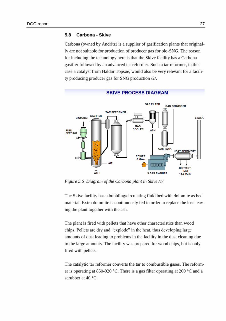
5.8 Carbona - Skive
Carbona (owned by Andritz) is a supplier of gasification plants that original-
ly are not suitable for production of producer gas for bio-SNG. The reason
for including the technology here is that the Skive facility has a Carbona
gasifier followed by an advanced tar reformer. Such a tar reformer, in this
case a catalyst from Haldor Topsøe, would also be very relevant for a facili-
ty producing producer gas for SNG production /2/.
Figure 5.6 Diagram of the Carbona plant in Skive /1/
The Skive facility has a bubbling/circulating fluid bed with dolomite as bed
material. Extra dolomite is continuously fed in order to replace the loss leav-
ing the plant together with the ash.
The plant is fired with pellets that have other characteristics than wood
chips. Pellets are dry and “explode” in the heat, thus developing large
amounts of dust leading to problems in the facility in the dust cleaning due
to the large amounts. The facility was prepared for wood chips, but is only
fired with pellets.
The catalytic tar reformer converts the tar to combustible gases. The reform-
er is operating at 850-920 °C. There is a gas filter operating at 200 °C and a
scrubber at 40 °C.

DGC-report 28
The Skive facility is in operation, but there have been frequent stops for
repair and modifications. In particular, the tar reformer has created prob-
lems. The plant supplies gas to a gas engine (5.5 MWe) that supplies heat
and electricity to Skive District Heating.
By using steam and oxygen for gasification instead of air the Carbona tech-
nology can be adapted for bio-SNG production. E.ON is contemplating this
technology for their future 200 MW facility in the south of Sweden.
Contact
Kari Salo, CARBONA or Skive Fjernvarme I/S (Skive District Heating).
5.9 The Pyroneer gasifier
Pyroneer is especially interesting for multifuel conversion because the tech-
nology is using a double fluid bed system, which gives relatively low tem-
peratures in the system. In this way e.g. the alkali metals can be preserved in
solid state that does not agglomerate on surfaces. Therefore, almost all types
of biomasses can be utilised. This makes the process very flexible.
Figure 5.7 Illustration of the LT-CFB technology in Pyroneer /6/
Pyroneer is a product of cooperation between Danish Fluid Bed Technology
ApS (DFBT) and DONG Energy. DONG Energy acquired IPR of the tech-
nology.

DGC-report 29
The technology is based on LT-CFB (Low Temperature Circulating Fluid-
ised Bed) for production of producer gases used for co-firing the boiler at
the power plant Asnæsværket.
At the moment the plant is adding up to 10 % straw directly to the coal to be
fired into the boiler. With this new technology the straw is gasified and then
only the gases are added. Thus the amount of biomass could be increased.
If steam and oxygen or pure steam were used, the Pyroneer technology
could produce syngas (primarily H2, CO and CO2), which then could be
methanised into bio-SNG.
Contact
Martin Møller
Innovation Manager, Project Execution
DONG Energy
Tel.: +45 99 55 40 97
5.10 Viking gasifier, Weiss
Boiler manufacturer Weiss has further developed the DTU multistep gasifier
“Viking-forgasseren”. In Hadsund, a facility with this technology has been
established. First in this technology the biomass is dried, then pyrolyzed
(degassed) and, finally, the coke residue is gasified in combination with
cracking of tars, which in this way are eliminated. The system produces a
highly pure gas to be used in gas engines. Figure 5.8 shows a diagram of the
Viking gasifier.

DGC-report 30
Figure 5.8 Diagram of the Viking gasifier from Weiss /43/
The gasification part works with a very high efficiency and the drying and
pyrolysis methods could be of interest in combination with other gasifica-
tion methods to make a producer gas for bio-SNG with high efficiency.
Contact
Weiss A/S
Tel.: +45 9652 0444
5.11 Firgas Alternating Gasifier, Ammongas and Vølund
The Firgas concept by Ammongas and B&W Vølund is a new concept un-
like any other gasification technology. The gasification process is alternat-
ing, which means that the two gasification reactors are in operation for a
short period (10-20 minutes) and the gas is stored. Then the gasification is
stopped and one of the catalysts is heated with a part of the produced gas
(10-20 minutes). Then the gasification is started again in the opposite direc-
tion for the same period of time, while the heat in the just heated catalyst is
utilised for the gasification. In the last of the four operations, the second
catalyst is heated and then the four operations start over again. Figure 5.9
shows a diagram of the concept.

DGC-report 31
Figure 5.9 The Firgas Alternating Gasifier by Ammongas and Babcock &
Wilcox Vølund /44/
The concept has several advantages and also disadvantages. The advantages
are:
Recirculation of producer gases, which are heated and used for gasi-
fication of biomass
No movement of heat storage material
Tar cracking and reforming in high-temperature catalysts
Absorption Enhanced Reforming (AER) technology by chemical
looping included
The disadvantages of the technology are:
The production of the producer gases is discontinuous, necessitating
a gas storage facility
The quality of the producer gas is varying due to varying tempera-
ture levels of gasification

DGC-report 32
The producer gas is meant for direct utilisation in an engine for electricity
production. The technology, however, is very interesting, and parts of the
technology might be used for bio-SNG gasification plants, e.g. the recircula-
tion of producer gases and the AER technology.
Contact
Babcock & Wilcox Vølund A/S
Thomas Norman
Tel.: (+45) 76 14 34 00

DGC-report 33
6 Sweden
6.1 The Chalmers gasifier
At Chalmers University of Technology (Sweden) a pilot project is installed
in order to gain experience with gasifiers and as a preparation for the GoBi-
Gas project. It is a circulating fluid bed, and it produces 2-4 MW producer
gas, which is used in a boiler. The gasifier is built as an add-on and retrofit-
ted to a larger fluid bed reactor (10-12 MW), where biomass is combusted,
and which supplies heat to the university. Figure 6.1 shows a diagram of the
Chalmers gasifier.
Part of the circulating fluid bed material can be led to the gasifier where the
hot sand circulating in the bed transfers heat to the gasification. Chalmers is
using sand only in the gasifier because it is a very durable material, which is
well known as bed material.
It is one of Europe’s (except for the Güssing gasifier) largest pilot plants for
gasification of biomass. On this gasification plant a number of smaller sub-
devices can be tested and substreams extracted from different places. In this
way, the subprocesses can be analysed.
This is part of the preparation for the GoBiGas project and other Swedish
gasification projects. The GoBiGas project uses the principles from the
Chalmers gasifier on the first 20 MW plant in Gothenburg.

DGC-report 34
Figure 6.1 Diagram of the Chalmers gasifier /36/
Contact
Henrik Thunman
Head of Division/Associate Professor
Chalmers University of Technology, Energy Technology
SE-412 96 Gothenburg
Sweden
Tel.: +46 31 772 1451
E-mail: [email protected]
6.2 The GOBIGAS project
The Swedish Energy Agency has granted 222 million SEK to the
GOBIGAS project in Gothenburg. First, the project will use the Güssing
technology and the Chalmers technology for production of 20 MW SNG.
Later, an 80 MW SNG plant is to be built using a technology that has not
yet been decided. EU ratified the grant in December 2010, where it was not
considered state aid with a negative market influence.

DGC-report 35
The GOBIGAS project is the world’s first large-scale commercial plant for
generation of SNG from biomass via gasification. The plants in Austria
(Güssing and Oberwart) are semi-commercial, as they receive continuous
subsidies for participation in research projects in addition to the revenue of
electricity and heat production.
The GOBIGAS project is part of Göteborg Energi’s vision of becoming
independent of natural gas over a period of years. This can be achieved by
replacing natural gas by RE gases that are upgraded to natural gas quality
and injected into the grid.
In Sweden, natural gas is not considered as environmentally friendly as in
many other countries. The argument being that it is a fossil fuel to be im-
ported. The attitude towards biogas, on the other hand, is very positive. To-
day, Sweden uses as much biogas as does Denmark, but quite a lot of the
biogas in Sweden is upgraded for use in vehicles as well as in the natural
gas grid.
The potential for RE gas in Sweden has been calculated to 14 TWh/year
from digestion and 59 TWh/year from gasification. The gasification plant in
Gothenburg is a first actual step to meet this.
The idea of GOBIGAS is to convert wood, wood chips and other types of
biomass to a gasification gas that will be upgraded and conditioned for the
natural gas grid. Very large amounts are planned. In the first phase, a gasifi-
cation plant in the size of 20 MW will be built. This plant is expected to be
commissioned at the end of 2013. A couple of years later, 80 MW will be
added to reach a total output of 100 MW, corresponding to a small power
plant in 2016-2018.
The GOBIGAS plant is built in Ryahamnen/Rya Harbour in Gothenburg.
This will offer the opportunity of having biomass supplied by sea and by
land. The supply of the large amounts of biomass for generating 100 MW
SNG requires a well-developed infrastructure in the local area. The location
in Ryahamnen ensures the supply of biomass by vessel, by rail and by road.
DGC-report 36
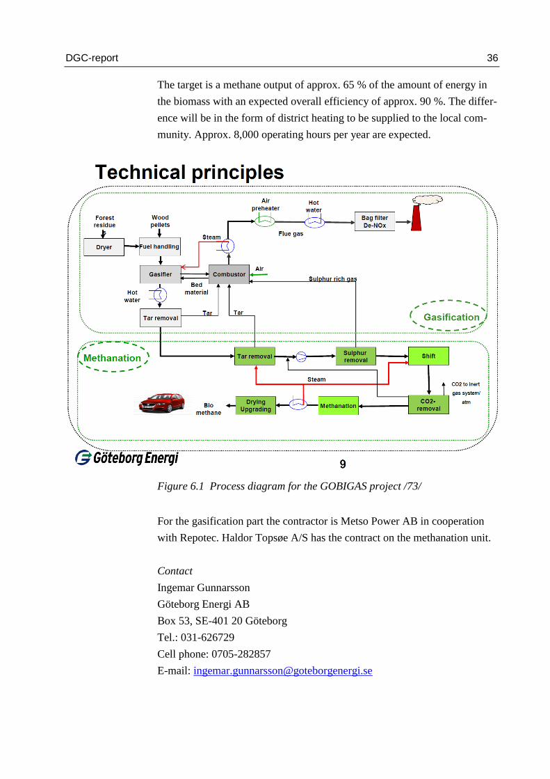
The target is a methane output of approx. 65 % of the amount of energy in
the biomass with an expected overall efficiency of approx. 90 %. The differ-
ence will be in the form of district heating to be supplied to the local com-
munity. Approx. 8,000 operating hours per year are expected.
Figure 6.1 Process diagram for the GOBIGAS project /73/
For the gasification part the contractor is Metso Power AB in cooperation
with Repotec. Haldor Topsøe A/S has the contract on the methanation unit.
Contact
Ingemar Gunnarsson
Göteborg Energi AB
Box 53, SE-401 20 Göteborg
Tel.: 031-626729
Cell phone: 0705-282857
E-mail: [email protected]

DGC-report 37
6.3 The E.ON project, Bio2G
E.ON has similar plans of an even larger gasification plant in Scania
(Skåne), probably in Trelleborg or in Malmö. This plant is planned to have
an output of 200 MW natural-gas quality gas and to be commissioned be-
fore 2020. No decision on exact location has been taken, yet, but the prereq-
uisites are connection to natural gas grid, a district heating grid for removal
of heat and a harbour for transport of the biomass.
Nor has the technology been decided, yet, but it is contemplated to use the
Carbona technology, even though it is not directly suited for the SNG pro-
duction. The Carbona technology is a direct gasifier, but by using oxygen
together with steam or CO2 it is possible to achieve a producer gas that can
be used for SNG. The advantage is a producer gas with high content of me-
thane.
For the moment (end of 2013) the project is on hold and awaits solid politi-
cal support with firm policies on subsidies etc. /54/.
Figure 6.3 Schematic process diagram showing E.ON’s Bio2G project /54/

DGC-report 38
Contact
Dr. Björn Fredriksson Möller, Project Director
E.ON Gasification Development AB
E-mail: [email protected]
6.4 CORTUS-WoodRoll three-stage gasification
The CORTUS-WoodRoll technology has three stages: drying, pyrolysis and
gasification. The technology has been demonstrated with woodchips, waste
wood and sludge from the paper industry.
CORTUS has signed a 12-year contract for supply of a 5 MW facility to a
Swedish lime burning plant. The plan is to expand the facility to 25 MW.
Figure 6.4 shows a diagram of the technology.
Figure 6.4 The CORTUS three step gasification /11/
A part of the technology is the indirect gasification, where heat is trans-
ferred by means of heat pipes in the gasification section. The composition of
the producer gases is very suitable for methanation, as it has a very large
content of H2. The composition of the producer gas is approx:

DGC-report 39
H2: 60 %
CO: 15 %
CO2: 23 %
CH4, C2H4, C6H6: 1-2 % (mainly CH4)
The important thing here is that the ratio H2/CO is larger than 3, which
means that methanation may take place without preceding shift reaction. At
the same time there is a large content of CO2 in the gas, which makes it pos-
sible to methanise hydrogen completely and to optimally utilise the energy.
Therefore, the technology is very suitable for biomass gasification for bio-
SNG production. However, bio-SNG is not the primary focus of CORTUS.
In the autumn of 2011 a 500 kW demonstration project was successfully
carried out. The earlier pilot project was a successful 150 kW facility. The
efficiency from biomass to syngas was measured at 80 %.
Contact
Rolf Ljunggren, CORTUS AB
E-mail: [email protected]

DGC-report 40
7 Germany
7.1 Power to Gas (P2G), Werlte biogas plant
The Werlte biogas plant was built in 2002, and a part of the gas is upgraded
to natural gas quality and is injected into the natural gas grid. The biogas is
upgraded via traditional PSA (Pressure Swing Absorption). The capacity is
approx. 3.6 MW injected into the natural gas grid.
In 2011 there were two different demonstrations of P2G at the plant. In one
demonstration they used the separated CO2 component from the upgrading,
added hydrogen via electrolysis and then carried out methanation of the
mixture. In the other demonstration they mixed hydrogen directly with bio-
gas from the plant and then carried out methanation of the mixture. In the
latter case the methane from the biogas plant is led passively through the
methanation plant, which has certain advantages at temperature stabilisation.
Figure 7.1 shows the two principles.
Figure 7.1 Schematic diagram for the Power to Gas (P2G) project at
Werlte biogas plant /10/

DGC-report 41
Both demonstrations resulted in approx. 92 % methane, 4 % CO2 and 4 %
hydrogen in the SNG.
The demonstration described above is a part of a bigger plan for demonstra-
tion of P2G in Germany.
The plant is a 25 kW container based plant commissioned in 2009. It
has demonstrated upgrading of CO2 + H2 to CH4. The Werlte demonstra-
tion was part of this.
The -plus plant is a 250 kW plant that was put into operation in 2012.
The ß plant is a 6 MW plant that was put into operation in 2013 in coop-
eration with Audi and others, see Chapter 7.2 below.
The plant is expected to be a commercial product of more than 6 MW
and is expected to be introduced in 2015 /10/.
Contact
Dr. Michael Specht
Centre for Solar Energy and Hydrogen Research (ZSW)
Industriestr. 6
D-70565 Stuttgart / Germany
Tel.: + 49 711 7870 218
Fax: + 49 711 7870 200
E-mail: [email protected]
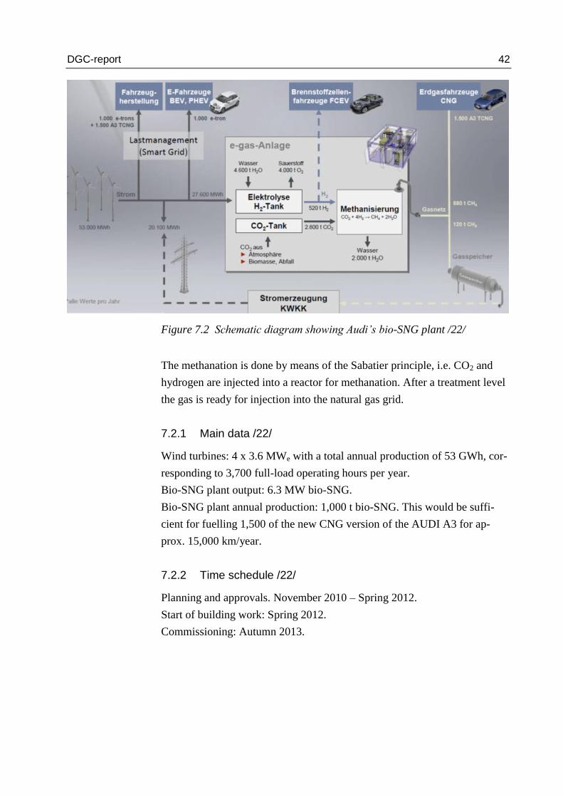
7.2 Audi project e-gas
In spring 2012 Audi (VW group) started the building of a plant in Werlte in
the northwest part of Germany. This plant is to generate bio-SNG based on
electricity from their own wind power plants in the North Sea and CO2 from
local biogas plants. The idea is that part of Audi’s future production of natu-
ral gas and electric vehicles is to be considered CO2 neutral.
DGC-report 42
Figure 7.2 Schematic diagram showing Audi’s bio-SNG plant /22/
The methanation is done by means of the Sabatier principle, i.e. CO2 and
hydrogen are injected into a reactor for methanation. After a treatment level
the gas is ready for injection into the natural gas grid.
7.2.1 Main data /22/
Wind turbines: 4 x 3.6 MWe with a total annual production of 53 GWh, cor-
responding to 3,700 full-load operating hours per year.
Bio-SNG plant output: 6.3 MW bio-SNG.
Bio-SNG plant annual production: 1,000 t bio-SNG. This would be suffi-
cient for fuelling 1,500 of the new CNG version of the AUDI A3 for ap-
prox. 15,000 km/year.
7.2.2 Time schedule /22/
Planning and approvals. November 2010 – Spring 2012.
Start of building work: Spring 2012.
Commissioning: Autumn 2013.
DGC-report 43
7.2.3 Project partners
Solarfuel
Fraunhofer IWES
ZSW
EWE
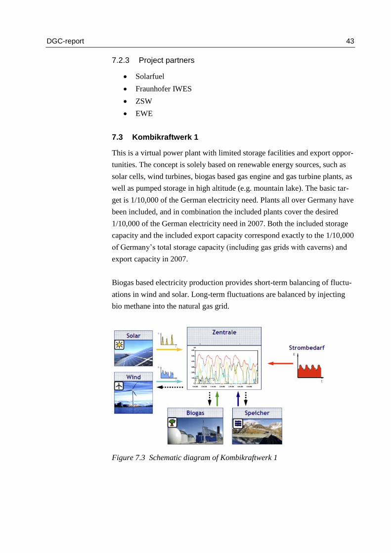
7.3 Kombikraftwerk 1
This is a virtual power plant with limited storage facilities and export oppor-
tunities. The concept is solely based on renewable energy sources, such as
solar cells, wind turbines, biogas based gas engine and gas turbine plants, as
well as pumped storage in high altitude (e.g. mountain lake). The basic tar-
get is 1/10,000 of the German electricity need. Plants all over Germany have
been included, and in combination the included plants cover the desired
1/10,000 of the German electricity need in 2007. Both the included storage
capacity and the included export capacity correspond exactly to the 1/10,000
of Germany’s total storage capacity (including gas grids with caverns) and
export capacity in 2007.
Biogas based electricity production provides short-term balancing of fluctu-
ations in wind and solar. Long-term fluctuations are balanced by injecting
bio methane into the natural gas grid.
Figure 7.3 Schematic diagram of Kombikraftwerk 1

DGC-report 44
The objective of the project was to demonstrate that with 100 % renewable
energy it is, in fact, possible to cover the German electricity need. Long-
term tests in the project period 2007 showed that this IS possible. It was
shown that
renewable energy can be controlled at any time
renewable energy units can inter-operate and cover the German electrici-
ty need
renewable energy can be outbalanced across the grid
7.3.1 Project partners
7.4 Kombikraftwerk 2
As a follow up on “Kombikraftwerk 1” (2007) the German federal govern-
ment has decided to start-up the project “Kombikraftwerk 2”.
This project will test how to handle grid stability with an energy supply that
is based on 100 % renewable energy. The project will investigate how to
optimise system services. First, the project will develop and via simulation
test how to optimise system services. In the last phase, the project will con-
nect energy plants all over Germany for test under realistic conditions.
The budget is EUR 1.8 million, and the project has a time frame of three
years. The project partners are:
Cube Engineering GmbH
Deutcher Wetterdienst
Enercon GmbH
Frauenhofer IWES
ÖKOBiT GmbH

DGC-report 45
Leibnitz Universität
Siemens AG
SMA Solar Technology AG
Solar World AG
Agentur für Erneubare Energien
7.5 Enertrag Hybridkraftwerk
In October 2011, Enertrag and project partners Total, Vattenfall and
Deutsche Bahn started up a so-called hybrid power plant located at Prenzlau
in northeast Germany. The plant comprises:
3 x 2 MW wind turbines
1 x 500 kWe atmospheric alkaline electrolyser
Biogas plant with 2 x 350 kWe biogas/hydrogen engines and biogas
storage facility
1 hydrogen compressor
Hydrogen storage facility with 1,350 kg hydrogen at 30 bar
Figure 7.4 Schematic diagram of hybrid plant /24/

DGC-report 46
The objective of the plant is to demonstrate that stable energy supply based
on RE in the form of wind and biogas is possible. The electricity surplus
from wind is converted via electrolysis to hydrogen. In case of electricity
shortage, biogas/hydrogen fuelled gas engines will supply the power. A
smart detail is that the gas mixing ratio of the engines can be varied accord-
ing to the availability of hydrogen and biogas, so that the hydrogen content
varies between 0 and 70 %.
The plant also supplies filling stations at Berlin Airport and in Hamburg
with hydrogen.
The price of the plant was approx. DKK 150 million.
7.6 Solarfuel and Juwi project P2G Morbach
In March 2011 (in the presence of the German Minister of the Interior), So-
larfuel and Juwi commissioned a small demonstration plant at Morbach.
This area already accommodates a number of energy plants, including wind
turbines, solar cell plants and biogas plants. This plant is a further develop-
ment of a laboratory plant that was in operation at ZSW in Stuttgart in 2010.
Figure 7.5 Location of demonstration plant in the existing network of ener-
gy plants at Morbach /25/
The container plant converts surplus electricity from solar and wind plants
to bio-SNG. The plant comprises a 25 kWe electrolysis plant and a succeed-

DGC-report 47
ing methanation plant of the Sabatier type. CO2 is supplied from a nearby
biogas plant.
Figure 7.6 Schematic diagram of the plant /25/
7.6.1 Time schedule
The plant is being optimised from 2011 to 2013. Market maturing and cor-
responding know-how regarding scaling up are expected to be achieved in
2014.
7.7 Project RH2-WKA
The project is one of the larger examples in Germany of storing surplus
electricity from wind power via electrolysis, of storing hydrogen and of re-
generating electricity via CHP plants. The project entered the project plan-
ning phase over the spring of 2011. The first turf was cut July 2011.
The project’s main components are:
1 MWe electrolyser (Hydrogenics)
Hydrogen compressor
Hydrogen storage facility 27 MWh
0.25 MWe CHP unit (gas engine based)
The plant is located close to a natural gas pipe, and the hydrogen produced
will partly be injected into the natural gas grid and partly used as transport
fuel.

DGC-report 48
The German Gas Regulations allow up to 5 % hydrogen content, which al-
lows a considerable hydrogen injection – if the gas flow conditions are sta-
ble.
Figure 7.7 Schematic diagram of the RH2-WKA plant /26/
The plant is located in Mecklenburg-Vorpommern in the northern part of
Germany, where wind conditions are favourable. The plant is placed at a
170 MWe wind farm, where the unit sizes vary from 5 MWe and upwards.
The company Wind-Wasserstoff-projekt GmbH has built the plant. Electro-
lyser etc. are sponsored by NIP (a national innovation program for hydrogen
and fuel cells).
7.8 E.ON Falkenhagen electrolysis and hydrogen in gas grids
In 2013 E.ON installed a pilot plant for production and injection of hydro-
gen in the local Ontras gas network in Falkenhagen in the northwest part of
Germany. Hydrogen is generated via electrolysis from surplus electricity
from local wind turbines /27/. The plant capacity is 360 Nm3/h.
DGC-report 49
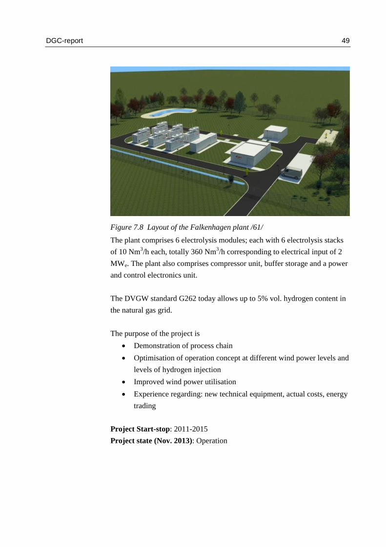
Figure 7.8 Layout of the Falkenhagen plant /61/
The plant comprises 6 electrolysis modules; each with 6 electrolysis stacks
of 10 Nm3/h each, totally 360 Nm
3/h corresponding to electrical input of 2
MWe. The plant also comprises compressor unit, buffer storage and a power
and control electronics unit.
The DVGW standard G262 today allows up to 5% vol. hydrogen content in
the natural gas grid.
The purpose of the project is
Demonstration of process chain
Optimisation of operation concept at different wind power levels and
levels of hydrogen injection
Improved wind power utilisation
Experience regarding: new technical equipment, actual costs, energy
trading
Project Start-stop: 2011-2015
Project state (Nov. 2013): Operation

DGC-report 50
Project partners
E.ON
ONTRAS-VNG Gastransport
Hydrogenics
Contact
E.ON
7.9 Power-to-gas plant Hamburg, Reitbrook
The project is similar to the Falkenhagen project, apart from the electrolyser
technology, which is PEM based. This technology enables a much more
compact design and the 1 MWe size PEM electrolyser is contained in only
one container. The similar power in Falkenhagen, which is based on the
traditional technology Alkaline electrolyser, occupies 3 containers. In this
project, for the first time the PEM electrolyser technology is scaled up 3
times from what has been demonstrated elsewhere (ITM has recently sup-
plied a 320 kWe PEM based unit for the Thüga project group in Frankfurt).
Figure 7.9 Layout of the Hamburg-Reitbrook P2G plant /61/
The main goals of the project are
Development of PEM technology
Field trial via injection into E.ON energy infrastructure
Development of business models
DGC-report 51
Project start-stop: 2012-2015
Project state (Nov. 2013): In progress
Project partners
E.ON Hanse AG (field trial)
Research centre Jülich
Hydrogenics (electrolyser system builder and packer)
Solvicore GmbH (PEM stack supplier)
Fraunhofer ISE
DLR
7.10 RWE demo, Ibbenbüren
This P2G demonstration plant is based on a 100 kWe PEM electrolyser unit
from the French company CERAM HYD. The produced hydrogen will be
injected in the local RWE gas network. The hydrogen production is 20
Nm3/h.
The project goals are:
Design and field test of a PEM based P2G unit.
Development of operation concepts to handle dynamic loads in the
electricity market.
Optimisation of plant design and operation.
Evaluation of P2G storage of electricity in an energy system based
on renewable energy.
Project start-stop: 2013-
Project state (Nov. 2013): Construction. Operation is scheduled to take
place later in 2013.
Project partners
RWE and CERAM HYD.
Contact
RWE

DGC-report 52
7.11 P2G demo Thüga Group
The P2G demonstration plant is based on a 320 kWe PEM electrolyser unit
from the English company ITM Power.
Figure 7.10 Priciple of the Thüga P2G demonstration plant /63/
Figure 7.10 indicates that the output of the electrolyser is 60 Nm3/h. This
means that stack efficiency is 60x3/320 = 0.56. Total plant efficiency is
somewhat lower due to consumption from blowers, pumps, standby heating
and power electronics.
The plant was delivered at the end of September 2013 at the site in Frank-
furt am Main. A test phase is scheduled to run for the next three months,
before injection into the gas distribution network starts up.
The project goals are:
Demonstration of PEM electrolyser in P2G setup.
Investigation of the ability to handle variable and very dynamic
loads.
Injection of hydrogen in the local gas distribution network at 3.5 bar.
Partners
badenova AG & Co. KG
Energieversorgung Mittelrhein GmbH
Erdgas Mittelsachsen GmbH
erdgas schwaben GmbH
e-rp GmbH

DGC-report 53
ESWE Versorgungs AG
Gasversorgung Westerwald GmbH
Mainova AG
Stadtwerke Ansbach GmbH
Stadtwerke Bad Hersfeld GmbH
Thüga Aktiengesellschaft (Projektkoordinatorin)
Thüga Energienetze GmbH
WEMAG AG
Project start-stop: 2013-
Project state (Nov. 2013): Test phase. After 3 months, the operation phase
is expected to begin.
7.12 P2G by Microbenergy: Eucolino at Schwandorf
The Viessmann owned company Microbenergy has installed a P2G plant in
Schwandorf. The system is based on an electrolyser of a capacity of 120
kWe and a 100 m3 biological reactor with the trade name “Eucolino”. The
biogas plant generates 10 Nm3/h biogas consisting of 52 % methane and
48 % carbon dioxide. In order to ensure complete transformation of the car-
bon dioxide the electrolyser has a capacity of 20 Nm3/h hydrogen. The hy-
drogen is directly injected and the methane content is increased from 52 to
around 75 % during the slow mixing process involving mechanical stirring.
The principle of the system is shown in Figure 7.11. The figure shows data
for a much larger system which is scheduled to be demonstrated in 2014
/64/.
Figure 7.11 Schematic diagram of the biologically based methanation

DGC-report 54
The 120 kWe R&D plant has been in operation since November 2011.
Partners
Microbenergy GmbH (a subsidiary of Viessmann)
7.13 DVGW-EBI research project: Storage of electrical energy
from regenerative energy sources in the natural gas grid – H2O
electrolysis and synthesis of gas components
The objective of the project is to develop relatively rapidly achievable con-
cepts for producing SNG from surplus electricity from solar and wind
plants.
Figure 7.12 shows the main components of the process flow to be investi-
gated. A crucial element is the CO2 source – here the project investigates
supply via biogas or chemical industry.
Figure 7.12 Schematic diagram of the process flow investigated /28/
The German potential for storage in the gas grid is considerable. At the
moment there is a storage capacity of 23 GNm3, and an additional 7 GNm
3
is planned. A total of 330 TWhe energy can be stored in these storage cav-
erns. In comparison, the pumped storage facilities hold 0.04 TWhe.
Project start-stop: 2011-
Project state (Nov. 2013): In progress
7.13.1 Project partners
H-tec (builds PEM electrolyser)

DGC-report 55
Fraunhofer ISE (system optimising)
DVGW (project coordinator og three-stage methanation)
IOLITEC (synthesis of ionic fluid)
Outotec (alternative methanation in Horden reactor)
Engler-Bunte-Institut (calorific value adaptation)
EnBW Energie (feasibility and identification of possible sites)
Contact
Dipl.Ing. Dominic Buchholz
DVGW Engler-Bunte-Institut Karlsruhe
E-mail: [email protected]
7.14 DVGW-GUT research project: Development of modular
concepts for generation, storage and injection of hydrogen into
the natural gas grid
The project started in 2010 and is based on the large five-year EU project
Naturalhy that was finalised around 2009 with 39 European partners. The
objective of Naturalhy was to investigate possibilities and consequences of
hydrogen injection into the gas grid.
As previously mentioned, DVGW G 262 already today allows a hydrogen
content in the gas grid of up to 5 % vol. Preliminary calculations with the
tool “Gascalc” in this project indicate that up to 15 % vol. hydrogen may be
allowable. 15 % hydrogen means that the gas mixture is still inside the qual-
ity band (Wobbe calorific value) that was established in DVGW G 260.
The project has now been finalised and a comprehensive report is freely
available for download /62/.
Project start-stop: 2010-2013
Project state (Nov. 2013): Finalised.
7.14.1 Project partners
DVGW-GUT
Fraunhofer IWES
Verbundnetz Gas AG
DGC-report 56
EON Ruhrgas
Engler-Bunte-Institut EBI
Contact
DVGW Hartmut Krause
E-mail: [email protected]
7.15 Absorption Enhanced Reforming at ZSW
Zentrum für Sonnenenergie- und Wasserstoff-Forschung (ZSW), Germany
has developed the AER technology which is used in gasification (Absorp-
tion Enhanced Reforming). It is an enhancement of the indirect gasification
technology with chemical looping including CaO (burnt lime). CaO is used
as bed material in the fluid bed gasification process. CaO contains energy
for the gasification process in the form of chemically latent heat which is
released when CaO absorbs CO2 and turns into CaCO3 (lime). The bed ma-
terial supplies heat into the gasifier – both as chemically latent heat and by
the thermal heat capacity /29/. See Figure 7.13.
CaO absorbs CO2, and the result of the gasification process is a producer
gas with a high content of hydrogen, which then again is directly convertible
to CH4, and the gas is prepared for SNG. In addition, CaO absorbs other
impurities, which then are not going to be extracted from the producer gas.
The absorbed materials in CaO can be used directly with the generated lime
on the farming fields, where the biomass originated from. This means ma-
nuring the fields.
Furthermore, CaO works as a catalyst for conversion of tar. The gas then
has a concentration below 500 mg/m3 of tar. If the pressure is increased,
both gasification temperature and combustion temperature rise equally,
which facilitates the conversion of tar, while the other advantages of CaO
are maintained.
There is only one drawback (yet discovered). When used as bed material,
CaO erodes. This material is found as dust together with the ashes from the
combustion of the biomass. If the level of erosion is too high, it can lead to
high costs. The preliminary results show that the quantity is less than the
usual amount added to fields by cultivation.
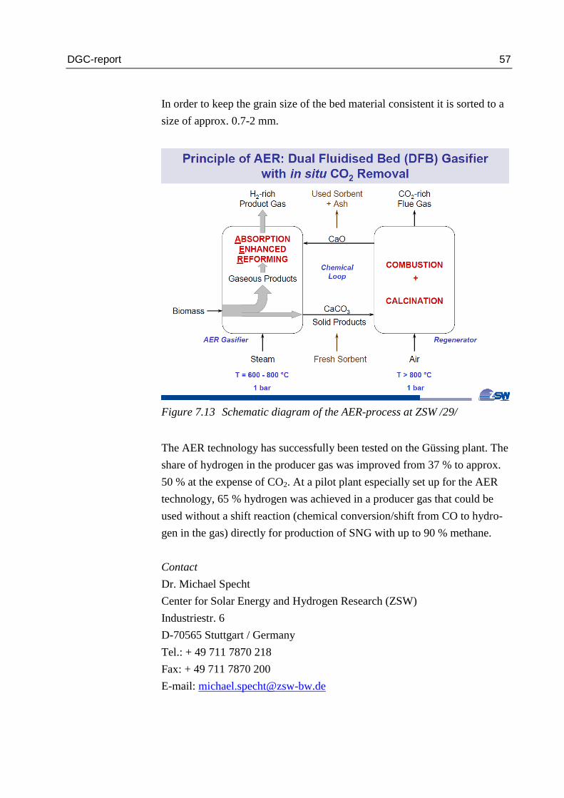
DGC-report 57
In order to keep the grain size of the bed material consistent it is sorted to a
size of approx. 0.7-2 mm.
Figure 7.13 Schematic diagram of the AER-process at ZSW /29/
The AER technology has successfully been tested on the Güssing plant. The
share of hydrogen in the producer gas was improved from 37 % to approx.
50 % at the expense of CO2. At a pilot plant especially set up for the AER
technology, 65 % hydrogen was achieved in a producer gas that could be
used without a shift reaction (chemical conversion/shift from CO to hydro-
gen in the gas) directly for production of SNG with up to 90 % methane.
Contact
Dr. Michael Specht
Center for Solar Energy and Hydrogen Research (ZSW)
Industriestr. 6
D-70565 Stuttgart / Germany
Tel.: + 49 711 7870 218
Fax: + 49 711 7870 200
E-mail: [email protected]

DGC-report 58
7.16 The Blue Tower concept
The German company Blue Tower GmbH owns the rights to a gasification
technology that relates to other gasification technologies, but is also differ-
ent from all other technologies. The technology could be called “Falling
Bed” technology, see Figure 7.14.
Figure 7.14 Diagram of the Blue Tower concept /14/
It is a three-stage gasification concept: Pyrolysis, gasification and reform-
ing. Depending on the biomass, a drying unit is placed at the front.
The Blue Tower concept is very interesting. Ceramic pellets (alumina,
Al2O3) are used as heat carriers. The gasifier consists of three levels: At the
top level the pellets are heated to approx. 1050 °C by the flue gas from
combustion of char. Pellets enter at the top of the reformer (after heating)
and move downwards by gravity, providing heat, first to reforming of the
pyrolysis gas with an ensuing low tar content and high hydrogen content,
next down to the pyrolysis unit where the biomass is added and pyrolysed in
conjunction with addition of steam. The char then moves with the pellets

DGC-report 59
down to separation (approx. 550 °C) where char is separated and combust-
ed. Pellets are transported and returned mechanically to the top of the upper
level at a temperature of approx. 550 °C, where they are again heated by the
flue gases from the char combustion. The gas is moving in counter flow
with the heat carrier, while char is moving downwards together with the
heat carrier. The residence time in the pyrolysis unit is approx. one hour
/37/.
A project (H2Herten) is planned in Herten, Germany. It is a 13 MW demon-
stration plant. More plants are being built in India and Japan, including a 30
MW plant in India meant for hydrogen production.
An interesting feature of the concept is that the producer gases could be
used directly for production of SNG. The producer gases have the following
composition (dry vol.):
H2: 50 %
CO: 15 %
CO2: 25 %
CH4, C2H4, C6H6: 10 % (mainly CH4)
H2O before drying ~20%
This leads to an H2/CO ratio above 3. Thus all hydrogen can be converted to
CH4 by methanation without a preceding shift reaction. Most other concepts
need such a shift reaction, but this concept includes automatic shift reaction
in the reformer. The gas leaves the reformer at a temperature of approx. 950
°C.
The concept aims at a water content of 20 % (vol.) out of the reformer,
which will pose no problem for an ensuing methanation. It is this relatively
high water content in the reformer that results in a shift reaction and tar re-
duction. The tar content from the reformer is very low.
Presently, this concept seems to be one of the most suitable concepts for
production of producer gas for bio-SNG production. After particle separa-
tion and tar and trace element removal the gas can directly enter the
methanation process for SNG production (e.g. TREMP). According to the

DGC-report 60
company the price per producer gas unit is lower in this concept than in oth-
er concepts. It would be possible to achieve a very high efficiency (probably
around 80 %), as the waste heat from the methanation process can be used
in the gasification process. Presently, the concept has not yet been demon-
strated with SNG production.
The only weakness of the concept seems to be the fact that each production
line can only have a fuel input of approx. 15 MW (the present limit). A 30
MW plant in India, therefore, has three lines in parallel, each of 10 MW,
which furthermore leads to larger operation reliability.
Contact
Dr. Heinz-Jürgen Mühlen
Blue Tower GmbH
Doncaster-Platz 5
45699 Herten
Tel.: +49(0)2366 58380-130
Fax: +49(0)2366 58380-230
E-mail: [email protected]
7.17 Heat Pipe technology
In the heat pipe technology heat is transferred inside pipes from exothermic
areas to endothermic areas, i.e. from combustion regions to gasification and
reforming regions. This technology, like the previous one, is an indirect gas-
ification technology.
The concept is illustrated in the below figure from agnion /38/. The research
and development has been carried out by agnion Highterm Research GmbH,
and the technology has been commercialised by agnion Technologies
GmbH in Pfaffenhofen a.d. Ilm, Germany /39/.

DGC-report 61
Figure 7.15 Illustration of the Heat Pipe heat transfer
The heat is transferred from the combustion chamber to the reform-
er/gasification via the so called heat pipes. Heat pipes are enclosed metal
pipes containing an alkali metal working fluid (e.g. Na or K). This working
fluid evaporates in the region of the exothermic combustion chamber fluid
bed (~900 °C) whereby it consumes energy, which is then released in the
region of endothermic gasification fluid bed (~800 °C) by condensation
/38/. The two regions on the outside of the pipes consist of bubbling fluid
beds.
Below is an illustration of the two bubbling beds and the heat transfer be-
tween them /39/.
Figure 7.16 The two fluid bed regions in the Heat Pipe reformer /38, 39/

DGC-report 62
A 500 kWth pilot plant has been in operation for some years. A commercial
plant was constructed and put into operation in May 2012 in Grassau.
Also other applications of this technology can be found /40/.
The advantages of this technology are, like other indirect gasifiers, that the
syngas is nitrogen free. On the other hand, the scale up advantages are lim-
ited due to a maximum unit size.
For the purpose of bio-SNG, agnion has developed a low cost methanation
unit, AMR (agnion methanation reactor), suited for the HPR (Heat Pipe Re-
former) of agnion. It is based on replacement of catalysts every 1-2 years of
operation. This means that the CAPEX cost is low, but the OPEX higher for
this methanation unit /41/.
Contact
Thomas Kienberger
Agnion highterm research GmbH
www.agnion.de
7.18 Super critical gasification of wet organic waste at the
Karlsruhe Institute of Technology (KIT)
KIT is an institution, like the Danish RISØ, that has been a development
centre for nuclear research, but is now doing research in RE. At the institute
in question they do research in gasification technologies with up to super
critical conditions of water, i.e. up to 500 bar and 600 °C.
KIT has succeeded in gasifying biomass at super critical conditions – so-
called hydrothermal gasification. The focus is on production of bio oil, but
the process may also be changed to production of gases, H2, CO, CO2 and
CH4. These gases may then be converted directly to SNG, via a catalyst,
which makes this technology very interesting.

DGC-report 63
Figure 7.17 Illustration of hydrothermal gasification at high pressure /12/
KIT does not recommend hydrothermal gasification for “dry” biomass, as
this material is difficult to access for the process, as the water is not “inside”
the material.
However, hydrothermal gasification can be used for all “wet” types of bio-
mass. For example slurry, products (sludge) from waste water treatment
plants, “wet” energy crops, residual products from biogas plants.
One of the advantages of the method is that the biomass is completely con-
verted at a relatively low temperature. Another advantage is that an in-situ
gas cleaning is carried out due to water’s properties in supercritical condi-
tions.
If the method is used as an “add on” for a biogas plant the residual product
from the biogas plant (often containing half of the energy) can be utilised,
and the total amount of gas products from both the biogas plant and the gas-
ification plant can be upgraded to CH4 at the same time. Of course, this
needs to be compared to a plant operating at 100 % hydrothermal gasifica-
tion.

DGC-report 64
At the moment, KIT is cooperating with PSI (Paul Scherrer Institute) in
Switzerland about gasification of residual products from biogas plants. KIT
is also cooperating with PNNL (Pacific North West National Laboratory) in
the USA, Douglas Elliott. PSI is working with processes just above the crit-
ical point of water, whereas PNNL is working with processes just below
this. Both methods have their advantages and disadvantages. Both result in
producer gases that can be methanised to SNG.
The pilot plant at KIT can convert up to 100 kg wet biomass per hour, cor-
responding to approx. 10 kg dry matter per hour. The future plant at PSI (in
cooperation with KIT) is planned to reach 200 kg/h, corresponding to 20 kg
dry matter/hour. This corresponds to approx. 100 kW.
A number of other institutions are working with supercritical gasification of
wet organic waste, but they are not included here.
Contact
Dr. Andrea Kruse, Karlsruhe Institute of Technology
Hermann-von-Helmholtz-Platz 1
76344 Eggenstein-Leopoldshafen
Tel.: +49 721 6082-3388
Fax: +49 721 6082-2244
E-mail: [email protected]
www.kit.edu

DGC-report 65
8 Switzerland
8.1 Paul Scherrer Institut
For many years, Paul Scherrer Institut (PSI) has been working with technol-
ogies for gasification and bio-SNG, but apparently there are only plants with
direct utilisation of the producer gas for CHP in Switzerland, at the moment.
PSI did participate in the Güssing project and supplied the technology for
methanation (1 MW bio-SNG).
PSI carries out a lot of fundamental research in gasification, combustion,
methanation and upgrading. Figure 8.1 shows a PSI overview of the applica-
tion range of key technologies for bio-SNG /51/.
Figure 8.1 Application range of key technologies for bio-SNG /51/
Contact
Paul Scherrer Institut
Dr. Serge Biollaz

DGC-report 66
9 France
9.1 GAYA project
With GDF-SUEZ as coordinator, the GAYA project was started in 2010
with support from the French government. The project is in collaboration
with a number of European players and companies, mainly from France,
though.
The project will run from 2010 to 2017, and the total budget is EUR 47 mil-
lion. The project covers gasification of dry biomass, first of all wood. The
FICFB process has been chosen for gasification, i.e. the same as in the
Güssing project. Repotec from Austria is technology supplier.
A gradual development from CHP over industrial utilisation to methanation
to bio-SNG has been chosen. See the figure below.
Figure 9.1 Stages of the GAYA project, coordinated by GDF-SUEZ /56/
The site for GAYA’s R&D platform is close to Lyon. First, gasification as a
kind of copy of the Güssing plant is going to be demonstrated, where the gas
is used in engines for production of CHP. Then, utilisation of the syngas
directly for industrial purposes will be demonstrated, e.g. glass works and

DGC-report 67
tile works, where the syngas will replace fossil fuels. Finally, methanation
will be demonstrated, where the gas is to be injected into the natural gas grid
and replace fossil natural gas /16/.
Contact
9.2 Cyrano-1-project: Wind farms connected to hydrogen grid
In the years 2009-2011 a feasibility study was carried out. For an area in
Brittany (France) with approx. 0.5 million inhabitants (Brest and Quimper)
and neighbouring wind farms (270 MWe) on the basis of
Mean electricity need on an hourly basis for the last 10 years
Mean wind/electricity production on an hourly basis for the last 10 years
the costs were calculated for a system consisting of
Wind turbines
Electrolysis plant
Hydrogen network
Hydrogen storage buffer
Fuel cell plant.
Figure 9.2 Schematic diagram of Cyrano-1-project /20/
The system was planned to balance differences in electricity production and
consumption.

DGC-report 68
Calculations were made on the system, both with and without connections
to the remaining French electricity grid. Furthermore, examples were calcu-
lated with limitations in the wind/electricity production. In all cases it was
found that the costs of electricity production were very high. As the separate
hydrogen network alone constituted 50 % of the installation costs, it was
suggested to use the natural gas grid for hydrogen transport – which, on the
other hand, entails a number of unsolved problems and costs.
9.2.1 Project partners
GDF-Suez
CEA
Helion
Ineris.
Contact
Remi Batisse, GDF Suez.
E-mail: [email protected]
9.3 GRHYD project
The GRHYD project includes two pilot projects that will be carried out in
Dunkerque. Both pilot projects include injection of wind/electricity based
hydrogen into the natural gas grid in the amount of 6-20 % vol. In one case,
the site is a well-defined residential area with 200 households i Capelle-la-
Grande in Dunkerque, and the other project will supply fuel for gas buses in
Dunkerque.
Project start-stop: 2013-2020
Project state: Study and preparation phase

DGC-report 69
Figure 9.3 Schematic diagram of GRHYD project /20/
9.3.1 Project partners
Contact
Remi Batisse, GDF Suez.
E-mail: [email protected]
9.4 Myrte (Corsica)
Solar electricity is feeding electrolysis supplying hydrogen to buffer storage.
Electricity is produced as needed by a fuel cell system for the electricity grid
of the island.
The project aims to test and optimise the system and control strategy in or-
der to minimise the constraints on the electricity grid caused by the intermit-
tence of the solar electricity. In other words, to optimise peak shaving and
load balancing.

DGC-report 70
The project is divided into three phases. In phase 1 the full solar array was
installed with a capacity of 560 kWe together with an electrolyser capacity
of 10 Nm3/h and a fuel cell capacity of 100 kWe. In phase 2, the capacity of
the electrolyser and fuel cell system was increased to reach an electrolyser
input/output capacity of around 110 kWe/23 Nm3/h and a fuel cell capacity
of 200 kWe. Phase 3 focuses on optimisation and reliability.
Figure 9.4 Myrte Site arrangement
Project start-stop: 2009-2015
Project state (Nov. 2013): Operation, phase 3
Project Partners
University of Corsica (Project Manager)
Areva Renewables
CEA
Contact
Jerome Gosset, Areva Renewables
9.5 Minerve
Minerve is an R&D project with the focus on flexible storage of CO2-free
electricity (based on renewables or nuclear) by converting CO2 emission
from industry into methane/bio-SNG or synthetic liquid fuels, such as meth-

DGC-report 71
anol and DME. The concept is based on high-temperature co-electrolysing
of water/steam and CO2 plus methanation.
The main advantage of the system, compared to systems equipped with the
usual low-temperature electrolyser, is that system efficiency in theory can
be higher. Such high-temperature electrolysis-based systems are not com-
mercially available now. The Danish company Haldor Topsoe is working on
similar systems based on the high-temperature SOEC (solid oxide electro-
lyser cells).
Figure 9.5 Principle diagram /69/
Project start-stop: ?
Project state: ?
Project partners
GdF-Suez (project manager)
CEA
KIT
AGH
Solvay
Contact
Sandra Capela, GdF-Suez/DRI-Crigen
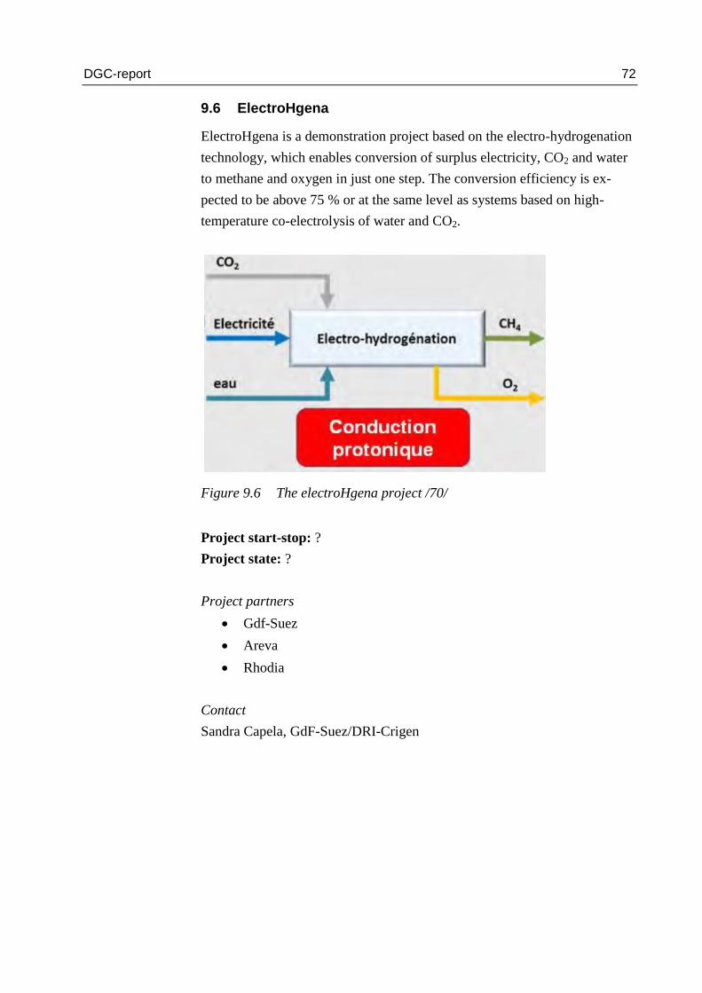
DGC-report 72
9.6 ElectroHgena
ElectroHgena is a demonstration project based on the electro-hydrogenation
technology, which enables conversion of surplus electricity, CO2 and water
to methane and oxygen in just one step. The conversion efficiency is ex-
pected to be above 75 % or at the same level as systems based on high-
temperature co-electrolysis of water and CO2.
Figure 9.6 The electroHgena project /70/
Project start-stop: ?
Project state: ?
Project partners
Gdf-Suez
Areva
Rhodia
Contact
Sandra Capela, GdF-Suez/DRI-Crigen

DGC-report 73
10 Italy
10.1 Ingrid, FCH JU project
Surplus of wind electricity is converted via electrolysis into hydrogen that is
stored in metal hydrides. Hydrogen is used for transport, industry, grid bal-
ancing and injection into gas network. The principle of the project is shown
in Figure 10.1.
The project was started in 2012 with a planning and preparation period. Ac-
cording to the project manager, the construction phase is expected to begin
December 2013. Project duration will be 4 years. The budget is 24 million
Euro, of which 14 million Euro is funded by the EU 7th
framework for re-
search.
Figure 10.1 Schematic layout of the project /65/
The project goals are /65/:
To maximise utilisation of fluctuating renewable energy sources by
increasing the efficiency of integration without compromising grid
reliability and security.
To design and make available advanced ICT monitoring and control
tools aimed at simulating, managing, monitoring, controlling power
dispatching in compliance with the power request of the grid, allow-
ing a correct balance between variable energy supply and demand.

DGC-report 74
To demonstrate the usage of an innovative hydrogen solid-state stor-
age technology as safe and high-density energy storage systems, to
be integrated in a closed loop coupled with water electrolysers and
fuel cell systems with the objective of achieving a high-efficiency
regenerative loop (larger than 50-60 %) at a reasonable cost.
To demonstrate the use of hydrogen for transport, industry, grid bal-
ancing and injection in the local gas network.
Project start- stop: 2012-2017
Project state: Planning. Construction will begin December 2013.
Project partners
Engineering Group
Enel Distributione
ARTI Puglia
RSE Italy
Hydrogenics
McPhy Energy
Tecnalia
Contact
Massimo Bertoncini, Project manager, Engineering Group (one of the large
consulting companies in Italy).
Email: [email protected]
Tel: +39 335 1038042

DGC-report 75
11 Spain
11.1 Sotavento
Surplus of wind electricity is converted via electrolysis into hydrogen that is
stored in tanks (5 MWh), and via a gas engine based ICE unit it is converted
to electricity as needed.
Figure 11.1 Schematic layout of plant /66/
The objectives of the project are
Maximising the utilisation of wind power
Production and storage of hydrogen from a wind farm that features
24 wind turbines of 5 different technologies
Using the H2 in an internal combustion engine to produce electricity.

DGC-report 76
Figure 11.2 Site arrangement /67/
11.1.1 Results of the project
The system control strategy was not optimised to handle fluctuating renew-
able energy. It showed difficult to model the various components
Project start-stop: 2007-
Project state: Operation
Project partners
Gas Natural Fenosa
Cener
Contact
Milagros Rey Porto
Email: [email protected]
Tel.: +34 934025217

DGC-report 77
12 Great Britain
There are a number of gasification projects in Great Britain, but no on-going
projects regarding bio-SNG have been identified.
Nor have any relevant projects for bio-SNG opportunities been identified,
apart from a couple of feasibility projects /30, 31/.

DGC-report 78
13 Finland
13.1 VTT Technical Research Centre of Finland
Finland has a number of institutions with a wide expertise in gasification
and a number of gasification projects have been identified. However, no
active projects regarding bio-SNG have been identified. Most projects based
on biomass are utilising CHP directly or aim at BtL (bio-to-liquids) for pro-
duction of liquid fuels. Finnish Carbona was technology supplier for Skive
District Heating that utilise the gasification for CHP.
The Technical Research Centre of Finland, VTT, has carried out research in
gasification and bio-to-fuel for several decades. In a recent project, “Woody
biomass based gasification process development for SNG or hydrogen syn-
thesis” (VETAANI), tar production and tar reduction in gasification were
thoroughly researched /52, 53/.
Figure 12.1 VTT concept for Syngas Route to Biofuels /53/
Contact
VTT Technical Research Centre of Finland
Ilkka Hannula

DGC-report 79
14 USA
14.1 Electrolysis projects based on RE
No large demonstration projects have been implemented, but research and
development have been going on for quite some years. However, no projects
with the objective of natural gas grid injection in the form of RE-SNG or
hydrogen have been identified.
One laboratory should be mentioned: NREL – National Renewable Energy
Laboratory. NREL is a national laboratory under US Department of Ener-
gy’s office for energy efficiency and renewable energy and it is led by “Al-
liance for Sustainable Energy, LLC”. Their special expertise is within sys-
tem engineering, integration, modelling, test and analysis. A major part of
their recent projects can be seen at their website /33/.
14.2 The Lurgi process – the Great Plains Synfuels Plant
The Lurgi process was developed in Germany in the 1930s for production of
SNG from coal. Through the 60s and 70s a couple of pilot and demonstra-
tion plants were built. So far, the only commercial plant for production of
SNG is Great Plains Synfuels Plant in North Dakota, US. This plant is based
on the LURGI processes for gasification and methanation. Figure 13.1
shows a process flow diagram of the plant /32/.The methanation part is in
some ways similar to the Haldor Topsøe TREMP process (or perhaps the
other way around).
Figure 13.1 Process flow diagram of SNG-plant at Great Plain Synfuel
based on the Lurgi process /32/

DGC-report 80
The plant in North Dakota began operating in 1984 and since 1999 it has
produced CO2 for EOR (Enhanced Oil Recovery) to a nearby oil field. Us-
ing Lurgi gasifiers, the Synfuels Plant gasifies lignite coal to produce valua-
ble gases, liquids and metals. Figure 13.2 shows the plant schematically.
Figure 13.2 The Great Plain Synfuel plant /42/
Contact
http://www.dakotagas.com/index.html
14.3 The SilvaGas plant
The technology in the SilvaGas gasifier is originally from a patent devel-
oped by Batelle in 1992. It consists of a double fluid bed system, where one
system is gasifying the biomass, and the other system is combusting the char
residue and thereby heating the bed material. This material releases the heat
in the gasifier. This principle is analogous with other indirect gasifiers, e.g.
the Güssing gasifier.
The previous owners of the IPR of the process went bankrupt in 2002 and
the IPR now belong to Rentech. A new plant based on this principle was
scheduled to be put into service in 2012 in California. Here the producer gas
was planned to be converted to liquid fuel. The producer gas from the pro-

DGC-report 81
cess is analogous with gases from other indirect gasifiers and they could just
as well be used for production of bio-SNG.
Figure 13.3 The SilvaGas-process /15/
Contact
www.rentechinc.com
14.4 GreatPoint Energy
GreatPoint Energy is an American company with a gasifying technology
where SNG is produced directly in the process – the so-called Hydro-
methanation. In this process, the feedstock material (such as coal or bio-
mass) is ground to less than the size of sand particles.
The first step in the hydromethantion process is to disperse the catalyst
throughout the matrix of a carbon-rich feedstock under specific conditions
so as to ensure effective reactivity. The catalyst/feedstock material is then
loaded into the hydromethanation reactor. Inside the reactor, pressurised
steam is injected to "fluidise" the mixture and ensure constant contact be-
tween the catalyst and the carbon particles. In this environment, the catalyst
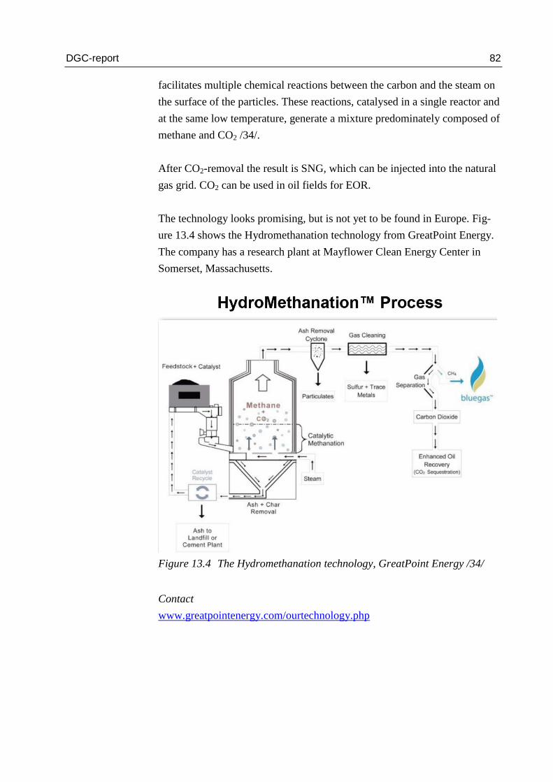
DGC-report 82
facilitates multiple chemical reactions between the carbon and the steam on
the surface of the particles. These reactions, catalysed in a single reactor and
at the same low temperature, generate a mixture predominately composed of
methane and CO2 /34/.
After CO2-removal the result is SNG, which can be injected into the natural
gas grid. CO2 can be used in oil fields for EOR.
The technology looks promising, but is not yet to be found in Europe. Fig-
ure 13.4 shows the Hydromethanation technology from GreatPoint Energy.
The company has a research plant at Mayflower Clean Energy Center in
Somerset, Massachusetts.
Figure 13.4 The Hydromethanation technology, GreatPoint Energy /34/
Contact
www.greatpointenergy.com/ourtechnology.php

DGC-report 83
14.5 Rentech-ClearFuels Biomass Gasification Process
The Rentech-ClearFuels biomass gasification technology produces hydro-
gen as well as syngas from cellulosic feedstocks through the use of a High
Efficiency Hydrothermal Reformer (HEHTR). The syngas can be used to
produce renewable power or be processed through Rentech's technology or
other third-party fuel conversion technology to produce renewable drop-in
fuels. The Rentech-ClearFuels technology has operated at pilot scale in ex-
cess of 10,000 hours and multiple third parties, including Idaho National
Laboratory and Hawaii Natural Energy Institute, have independently vali-
dated the results of the pilot scale data. The Rentech-ClearFuels technology
has been proven at demonstration scale at Rentech's Energy Technology
Center in Commerce City, CO through a $23 million grant received from
the U.S. Department of Energy under the American Recovery and Rein-
vestment Act /59/.
Figure 13.5 The Rentech-ClearFuels gasification process /59/
Unlike other gasifiers or pyrolysis processes, ClearFuels HEHTR is a one‐
step rapid steam reforming process that converts biomass to syngas with
minimal char, ash and tar yields. The technology has operational controls
for tuning the hydrogen to carbon monoxide ratio in the syngas product
from 1.0 up to 3.5 as shown in Figure 13.6, which presents syngas composi-
tion as a function of residence time in the ClearFuels gasifier. The tuning of
syngas composition provides flexibility for various downstream processing
and conversion options.

DGC-report 84
Wood waste from wood product facilities like sawdust or wood scrap and
sugar mill waste like bagasse and cane trash are two examples of many in-
expensive and readily available feedstocks for the process /58/.
Figure 13.6 Tuning of the Hydrogen to CO ratio in the syngas /58/
Unfortunately the test facility has now been shut down and the staff reduced
from 75 to a core group of 10, which is focusing on selling the technology,
the Production Demonstration Unit and the site in Commerce City /60/.
Apperently the process would, however, be very suitable for bio-SNG pro-
duction as the H2/CO ratio is easily adjusted to the desired 3.0 for methana-
tion.
H2
CO2
CO
CH4

DGC-report 85
15 Japan
At the moment, no relevant projects have been identified.
Japan has initiated a large number of projects related to a possible future,
where hydrogen might be a significant energy carrier. One example of these
projects is the “Hydrogen Town demonstration project”, which is imple-
mented in Fukuoka Prefecture, Kita-Kyushu-shi. As usual in Japan, the hy-
drogen generation is either industrial waste product or reformer based. The
project is demonstrating operation of fuel cell plants in households and ve-
hicles.
Figure 14.1 Schematic diagram of the Japanese town demonstration pro-
ject /35/

DGC-report 86
16 Argentina
16.1 Hychico
In the IEAHIA task 24 final report /66/, this project is described as follows:
“The project objective is to maximise wind utilization by producing hydro-
gen, which is admixed to natural gas and used as fuel in a genset. High-
pressure oxygen will be supplied to the local market.
The P2G and G2P plant has been into operation since 2008.
The project has two phases:
Phase 1 was the “Large Scale Clean Hydrogen Production in Patagonia Ar-
gentina” pilot project.
In Phase 1, two 325 kW electrolysers produce a total flow of 120 Nm³/h of
hydrogen and 60 m³/h of oxygen at max. 10 bar. For re-electrification, the
hydrogen is mixed with natural gas from an oil field. The 1.4 MW genset
supplies the oil field with power. Oxygen is compressed to 200 bar and
stored.
The genset has an ICE designed to operate with gases from biomass, pyroly-
sis, etc., and has been specially adapted to operate with rich and/or poor gas
– hydrogen mixtures. It is worth mentioning that gases used are raw gases
extracted from the field with no previous treatment. The rich gas has a 90%

DGC-report 87
methane content and the poor gas has a ~40 % CO2 content. It is planned to
use 3 years’ wind resource data as input signal to the electrolysers, in order
to simulate wind park behaviour.
Phase 2 is to be the start-up of a 6.3 MW wind park, which feed 0.6 MW to
the hydrogen plant, the remaining output being sold to the national inter-
connected electric system. “
Partners
Hydrogenics
Hychico

DGC-report 88
17 New Zealand
17.1 University of Canterbury
University of Canterbury (UOC) in Christchurch and CRL Energy Ltd in
Lower Hutt are the only two institutes in New Zealand to conduct research
and development on thermal gasification. UOC is focusing on biomass gasi-
fication and collaborating with CRL for co-gasification of biomass and coal
/57/.
Biomass gasification projects have been established and run since 2004 in
the Department of Chemical and Process Engineering (CAPE). A 100 kW
(biomass in) dual fluidised bed (DFB) gasifier has been designed, construct-
ed, commissioned and improved during 7 years. The concept of the DFB
gasifier was similar to the Güssing gasifier and the gasifier developed at
Vienna University of Technology (VUT). Collaboration has been estab-
lished between UOC and VUT. Modification of the gasifier has been con-
ducted for testing of New Zealand feedstocks /57/.
The current research programme conducted at the University of Canterbury
is Biomass to Syngas and Liquid Fuel (BTSL). The programme is funded by
the Ministry of Business, Innovation and Employment (MBIE) for six years
from 2008 to 2014. The programme is to adapt and develop the most ad-
vanced thermo-chemical conversion technologies to suit the New Zealand
biomass resources. These technologies include using gasification to convert
biomass into hydrogen-rich syngas followed by Fischer-Tropsch (F-T) syn-
thesis to produce biodiesel for transport.
Flexibility of the DFB gasifier has been demonstrated in producing producer
gases with a wide range ratio of H2 to CO from 0.9 to 4.4. This means that
the DFB gasifier developed can be used for generation of energy using the
producer gas of low ratio of H2 to CO, for generation of Fischer-Tropsch
syngas using the optimum H2 to CO ratio of 2, or for hydrogen production
using the high ratio of H2 to CO /57/.
This flexibility makes it very suitable for the production of bio-SNG as well.

DGC-report 89
18 Gas cleaning and conditioning
Gas cleaning is necessary between the gasification unit and the methanation
unit, which in most cases needs a clean and conditioned gas so as not to
damage the catalysts and other components.
There are a number of different gas cleaning concepts and techniques, but
common for all of them is the removal of substances that may compromise
the function (e.g. catalyst deactivation or poisoning) and the lifetime of the
components used downstream of the gasifier and to ensure the required
quality of the final product.
Many concepts are based on advanced and extensive gas cleaning, while
others are based on development of components that are more durable and
robust /45/.
The different technologies are:
Dust cleaning
Tar conversion/separation
Sulphur and chlorine removal
Reforming and shift processes
In the SGC report “Gasification – Status and technology” /45/ a short, but
thorough description of different technologies is presented, and it will not be
repeated here.
Dust cleaning is obviously necessary to avoid blocking of catalyst and other
mechanical components.
Tar conversion/separation is necessary for the same reasons, but at the same
time the energy content in the tar may be high depending on the gasification
technology. To increase the overall efficiency conversion is needed.
Sulphur and chlorine removal is obviously necessary to avoid destruction of
catalysts and to avoid corrosion of mechanical parts in the plant.

DGC-report 90
Reforming and shift are chemical processes that are necessary to condition
the syngas, i.e. to adjust the concentration of chemical components before
entering into the methanation process. In some gasification technologies,
however, these processes are included in the gasification and no further re-
forming or shift is needed.

DGC-report 91
19 Methanation technologies
Bio-SNG from gasification of biomass is only possible if a methanation unit
is installed after the unit producing the syngas.
In the methanation unit, hydrogen, carbon monoxide and carbon dioxide in
the syngas are converted to methane and water according to the following
reactions:
CO + 3H2 CH4 + H2O
CO2 + 4H2 CH4 + 2H2O
Methanation normally takes place over a nickel based catalyst at a tempera-
ture of approx. 250 – 450 ˚C. Both the above methanation processes are
strongly exothermic, and the methanation reactor is usually cooled by inter-
nally recycled gas and heat exchangers. The strong heat release is an im-
portant reason to choose a gasification technique and process conditions that
favour methane formation already in the gasification step.
19.1 Haldor Topsoe’s TREMP process
Haldor Topsoe A/S (HTAS) has developed the TREMP process which can
convert H2 and CO in the ratio 3:1 into methane. The result is SNG. The
premise is that the gasification products are conditioned to the TREMP pro-
cess (pure syngas).
In the TREMP process approx. 80 % of the energy in the feed gas is con-
verted into methane in a gas with up to 98 % methane. The rest of the ener-
gy (heat released during the process) can be delivered e.g. in the form of
pressurised steam, which can be used for power production, or otherwise
used in the gasification process (the production of the syngas).
Figure 15.1 shows HTAS’ TREMP technology. Figure 15.2 shows a dia-
gram of the process.

DGC-report 92
Figure 15.1 The TREMP technology of Haldor Topsøe [22]
Figure 15.2 Graphical illustration of the TREMP-process /46/

DGC-report 93
19.2 Methanation at PSI
The combined shift and methanation reactor developed at Paul Sherrer Insti-
tute (PSI) is based on fluid bed technology and works at low temperatures of
around 350 °C. It has shown to work at hydrogen/carbon monoxide ratios
within as broad an interval as 1 to 5 /45/.
In the PSI methanation process the carbon dioxide is separated after the
methanation, using conventional technology. This technology was used at
the Güssing gasification plant for demonstrating SNG production from gasi-
fication of wood chips. See Figure 15.3.
Figure 15.3 The methanation unit at the Güssing plant /32/

DGC-report 94
19.3 Methanation at ZSW
Another activity at Zentrum für Sonnenenergie- und Wasserstoff-Forschung
(ZSW), which was mentioned earlier in connection with the AER-process,
is testing of a methanation unit. This is a unit which was tested with 50 kW
production of SNG in a one-tube process. This process consists of one long
tube containing catalyst material. The temperature is kept at the right level
with a heat exchanger with melted salt at different temperature levels. See
Figure 15.4.
Figure 15.4 The methanation unit at Zentrum für Sonnenenergie- und Was-
serstoff-Forschung /29/
19.4 The agnion methanation reactor (AMR)
For the purpose of bio-SNG the company agnion has developed a low-cost
methanation unit, AMR (agnion methanation reactor), suited for the HPR
(Heat Pipe Reformer) of agnion. It is based on replacement of catalysts eve-
ry 1-2 years of operation. This means that the CAPEX cost is low, but the
OPEX higher for this methanation unit /41/.

DGC-report 95
The AMR could be applied for several different small-scale gasification
technologies with indirect gasification and suitable syngas composition, e.g.
CortusWoodroll, Blue Tower, MILENA, FICFB.
19.5 Bio-methanation
The idea of bio-methanation of gasification gas has developed as a result of
the studies in an earlier project at DGC /50/.
In an existing project supported by EUDP the company Electrochaea is
demonstrating a concept for biological methanation of CO2 and H2 to form
CH4. The CO2 here comes from a biogas plant and the H2 from electrolysis
of water using wind power.
This technology, however, could be used as the second part of a methana-
tion unit for gasification gas (producer gas). Producer gas consists of a mix-
ture of H2, CO2, CH4 and CO. In existing chemical methanation plants a part
of the CO of this mixture is first shifted to H2 in a “Shift”-reaction to con-
vert the energy in CO to H2. When sufficient CO is shifted, the mixture of
H2, CO and CO2 is converted to CH4, CO2 and H2O. The CO2 and water are
removed, and the remaining CH4 is bio-SNG.
These processes could be done by biological processes instead of chemi-
cal/thermal processes. A study of fermentation processes shows that some
microbes are able to convert CO and water to a mixture of H2 and CO2 /47/.
This process is exothermal, and the microbes use a part of the excess energy
for reproduction purpose. This biological process could be called a “biologi-
cal shift” reaction.
A combination of the above two biological reactions could form a full bio-
logical methanation process for converting producer gases from thermal
gasification to bio-SNG. Figure 15.5 shows in a diagram the method of bio-
methanation.
After a first cleaning of producer gas from a thermal gasifier, the gas con-
sists of a mixture of CO2, CO, CH4 and H2.
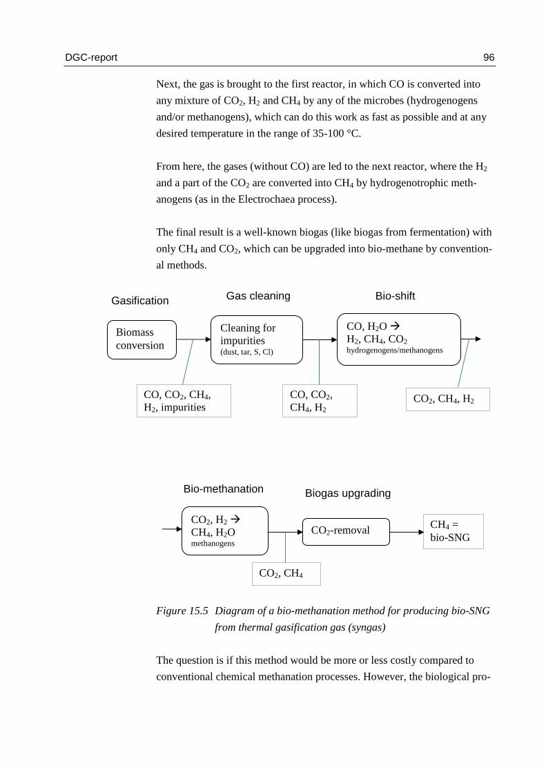
DGC-report 96
Next, the gas is brought to the first reactor, in which CO is converted into
any mixture of CO2, H2 and CH4 by any of the microbes (hydrogenogens
and/or methanogens), which can do this work as fast as possible and at any
desired temperature in the range of 35-100 °C.
From here, the gases (without CO) are led to the next reactor, where the H2
and a part of the CO2 are converted into CH4 by hydrogenotrophic meth-
anogens (as in the Electrochaea process).
The final result is a well-known biogas (like biogas from fermentation) with
only CH4 and CO2, which can be upgraded into bio-methane by convention-
al methods.
Figure 15.5 Diagram of a bio-methanation method for producing bio-SNG
from thermal gasification gas (syngas)
The question is if this method would be more or less costly compared to
conventional chemical methanation processes. However, the biological pro-
Biomass
conversion
Cleaning for
impurities (dust, tar, S, Cl)
CO, H2O
H2, CH4, CO2 hydrogenogens/methanogens
CO, CO2, CH4,
H2, impurities
Gasification Gas cleaning Bio-shift
CO2, H2
CH4, H2O methanogens
CO2-removal
CO, CO2,
CH4, H2 CO2, CH4, H2
Biogas upgrading Bio-methanation
CO2, CH4
CH4 =
bio-SNG

DGC-report 97
cesses are known to be very fast, and the reactors can be made very concen-
trated (small volume per production unit).
The resulting gas would be conventional biogas and by that subject to sub-
sidies in parallel to conventional biogas plants. The gasification plant would
act as a “thermal pre-treatment” of the biomass before the fermentation in
the bio-shift and bio-methanation reactors.
This method would have several advantages:
The methanation unit is less sensitive to changes in syngas concen-
trations
Easy shut down and start up (the microbes just sleep and wait
dormant for a new start up)
The unit could be made both small- and medium-scale (perhaps
large-scale)
The output is conventional biogas
Small footprint for the methanation unit
Low-priced??
No plants of this kind have yet been built, but the technologies exist and
seem promising. Plants like these for ethanol production have been built in
USA /48, 49/. Hence, the idea is not new, only the purpose of bio-SNG is
new.

DGC-report 98
20 Possible small-scale demonstration projects
20.1 Demonstration project for gasification in Denmark
All Danish gasification technologies are characterised by the fact that the
producer gases – immediately after gasification – are used in a boiler or an
engine. This use is initially the most effective because after purification and
without modification the gases can be used directly in a boiler or an engine.
However, a gasifier plant is rather expensive, which means that in order to
be cost-effective the gasifier must operate as base load. In the future, an
expectably larger production of producer gases will, therefore, cause a need
for storage of the energy – because there won’t be correspondence between
production and utilisation. This storage is possible by producing bio-SNG
by methanation and then adding it to the natural gas grid and storage facili-
ties.
There are two ways of making gasification plants more cost-effective:
“Economy of scale” and “Economy of number”. Large plants, of course,
have the advantage of lower specific price for the installation. On the other
hand, a great number of similar plants scattered across the country would
also reduce the specific cost of installations and the expenses for transport
would be reduced, as well.
A third possibility is to install at a plant several parallel units for gasification
technologies that have maximum unit size and attaching one common
methanation unit. This would increase the operational reliability of the plant
and save installation costs where possible.
In Denmark, as an example, a plant of 60 MW (output) might be considered,
corresponding to approx. 75 MW input. It could correspond to 5-6 unit lines
in parallel with very high operation reliability (10-12 MW as unit size). It
would be a possibility to install a common (relatively cheaper) methanation
unit (e.g. TREMP) after the gasifiers. This methanation unit could also sup-
ply steam to the gasification process itself achieving a synergy effect and
increasing efficiency.

DGC-report 99
There are several small- to medium-scale technologies well suited for bio-
SNG production, e.g. Cortus WoodRoll, Blue Tower (Concord Blue),
agnion, MILENA and others.
Even the Danish gasification technologies Viking and Firgas in combination
would theoretically be a high-efficient small- to medium-scale unit for bio-
SNG production combined with e.g. the AMR methanation from agnion or
perhaps future bio-methanation technology /50/.
Small-scale demonstration projects with these technologies should be sup-
ported.
20.2 Demonstration of DTU’s hydrogen injection into biogas
plants
Hydrogen injection directly into biogas plants seems to be an elegant meth-
od of using surplus electricity for methane production. The bacteria in a
biogas plant are already converting hydrogen and CO2 to methane so that
approx. ¼ of the methane from a biogas plant is generated in this way.
When additional hydrogen is added, the bacteria are slowly becoming used
to a higher amount of hydrogen and will convert this with surplus CO2 to
additional methane. By storing hydrogen locally, it is possible to balance the
peak load of wind energy and to use the hydrogen continuously in the bio-
gas plant. This will result in an alternative upgrading process that at the
same time increases the total methane generation from the biogas plant.
Demonstration of this process needs to be supported.

DGC-report 100
21 Abbreviations and glossary
AER: Absorption Enhanced Reforming
Allothermal: Indirect heating in the gasification process
AMR: agnion methanation reactor
Anaerobic: With no addition of oxygen
Biogas: Gas product from biological low-temperature conversion
of biomass by anaerobic digestion process
Bio-SNG: Substitue (or Syntetic) Natural Gas from biomass
Chalmers: Chalmers University of Technology
CH4: Methane
CO: Carbon monoxide
CO2: Carbon dioxide
DFB: Dual Fluidised Bed
DTU: The Technical University of Denmark
ECN: Energy research Centre of the Netherlands
EOR: Enhanced Oil Recovery
EUDP: Energiteknologiske Udviklings- og DemonstrationsProjek-
ter (Energy Technology D&D projects)
FICFB: Fast Internally Circulating Fluidized Bed
Firgas: Gasification concept by Ammongas and B&W Vølund
Gasification: Thermal/chemical conversion of biomass into gas at high
temperature
GOBIGAS: Gasification project in Gothenburg with the goal of pro-
ducing up to 100 MW bio-SNG
H2: Hydrogen
HHV: Higher heating value
HPR: Heat Pipe Reformer
HTAS: Haldor Topsøe A/S
Hydromethanation: Methanation by means of water and/or hydrogen
kWh: Unit of energy = 3,6 MJ = 3,6·106 Joule
LHV: Lower heating value
LT-CFB: Low Temperature - Circulating Fluid Bed
Methanation: Chemical conversion of gasification gases to a gas pre-
dominantly consisting of methane
MILENA: Gasification process developed at ECN in the Netherlands

DGC-report 101
OLGA: Process developed in the Netherlands for removing tar
from gasification gases
ORC: Organic Rankine Cycle
PJ: Unit of energy = 1015
Joule
RME: Bio-oil, bio-diesel
SNG: Substitue (or Syntetic) Natural Gas
Syngas: A mixture of H2, CO and CO2 (+possibly CH4)
TREMP: Methanation process developed at Haldor Topsøe A/S
Viking gasifier: Multi step gasification concept offered by Weiss
VUT: Vienna University of Technology
VTT: Technical Research Centre of Finland (Valtion Teknillinen
Tutkimuskeskus)
ZSW: Zentrum für Sonnenenergie- und Wasserstoff-Forschung

DGC-report 102
22 References
1. Kari Salo, 2008. Topsoe Catalysis Forum, 21-22 August 2008.
2. Kari Salo, 2010. Private communication. Visit at Skive Forgasningsan-
læg.
3. Electrochaea, 2011. Non-confidential information and personal commu-
nication from Eletrochaea, 2011.
4. Haldor Topsoe, 2011. Presentation at Seminar on renewable energy gases
and gas network, Energinet.dk, 2011.
5. Green Natural Gas, 2011. Edited from application to EUDP.
6. DONG Energy, 2011. Edited from application to ForskEL.
7. FiB nr. 37, 2011. Metangas kan blive en genvej til brintsamfundet. Irini
Angelidaki, Gang Luo & Poul Lyhne.
8. Reinhard Rauch, TU77V, 2009. SGC Gasification Seminar Stockholm,
2009.
9. Hermann Hoffbauer, TUV, 2011. Presentation at International Gasifica-
tion Seminar, Malmö, 2011.
10. Michael Specht, ZSW, 2011. Power-to Gas conference, Bundes-
netzagentur/Fraunhofer IWES, nov. 2011.
11. Rolf Ljunggren, Cortus, 2011. Præsentation ved International Gasifica-
tion Seminar, Malmö, 2011.
12. Andrea Kruse, KIT, 2010. Presentation at International Gasification
Seminar, Gøteborg, 2010.
13. Björn F. Möller, 2011. Presentation at International Gasification Semi-
nar, Malmö, 2011.

DGC-report 103
14. Heinz-Jürgen Mühlen, Blue Tower, 2011. Presentation at International
Gasification Seminar, Malmö, 2011.
15. Risø, 2010. Bio-SNG potential assessment, Risø & DGC, 2010.
16. GDF-Suez, 2011. Presentation at IGRC, Seoul 2011.
17. Dansk Mikrokraftvarme, 2011. Dansk Mikrokraftvarmes web-site.
www.dmkv.dk.
18. Göteborg Energi, 2010. Presentation at meeting.
19. ECN 201. Comparing the options to produce SNG from biomass, May
2010, Lyon France.
20. Presentation at IEA HIA task 28 workshop, September 2011, Berlin.
Remi Batisse, GDF-Suez.
21. Pilot Project on Hydrogen Injection in Natural Gas on Island of Ame-
land in the Netherlands. M.J. Kipper et.al., Kiwa Gas Technology. Present-
ed at IGRC 2011.
22. Reiner Mangold, Audi AG, Project e-gas: Power-to-gas im
Verkehrssektor.
23. www.kombikraftwerk.de
24. www.enertrag.de
25. Alexandra Ernst, juwi, Presentation at Power-to-gas workshop, Berlin,
Nov. 2011.
26. M. Weiße. Projekt RH2-WKA Making Wind Energy a Steady Power
Source. Presented at WHEC 2010, Essen.
27. www.eon.com. Press release 11. november 2011.

DGC-report 104
28. www.fona.de. Speicherung elektrischer Energie aus regenerativen
Quellen im Erdgasnetz – H2O-Elektrolyse und -Synthese von Gaskomponen-
ten.
29. Zentrum für Sonnenenergie- und Wasserstoff-Forschung, 2011. Presen-
tation at meeting ZSW 2011.
30. The potential for bio-SNG production in the UK. Final report E4Tech.
NNFCC project 10/005. April 2010.
31. Bio-SNG. Feasibility Study. Establishment of a regional project. 10 No-
vember 2010. Progressive Energy & CNG Service for NEPIC.
32. Jan Kopiscinski 2010. Article in Fuel 89, p. 1763-1783.
33. www.nrel.gov/hydrogen/renew_electrolysis.html
34. GreatPoint Energy 2008. Presentation on web-site.
www.greatpointenergy.com/ourtechnology.php
35. Japan country update. Presentation at IEAHIA Task 28 workshop, Sep-
tember 2011, Berlin.
36. Henrik Thunman, International Seminar on Gasification, Göteborg
2010.
37. Blue Tower GmbH, private communication.
38. The agnion Heatpipe Reformer, ICPS, 2011. http://www.agnion.de/
39. SGC Newsletter 2, 2011.
40. http://www.hsenergie.eu/en/home/products/hp-dry/
41. agnion, private communication
42. Great Plain Synfuels website, http://www.dakotagas.com/index.html

DGC-report 105
43. Weiss flow-sheet. IEA Bioenergy, Task33.
44. FIRgas, internal presentation, Vølund, Ammongas, 2012.
45. SGC-report 240, Gasification – Status and technology, 2012.
46. Roberta Cenni, HTAS, EGATEC, May 2011.
47. Ellen Oelgeschläger, Michael Rother, Carbon Monoxide-dependent en-
ergy metabolism in anaerobic bacteria and archaea, 2008.
48: http://www.coskata.com/process/
49. http://www.ineosbio.com/57-Welcome_to_INEOS_Bio.htm
50. Niels Bjarne Rasmussen, Technologies relevant for gasification and
methanation in Denmark, DGC, September 2012
51. Serge Biollaz, Progress in R&D for next generation methanation tech-
nologies, Presentation at SGC International Seminar on Gasification 2013.
52. Jörgen Held, Feedback report on VETAANI project, SGC 2013
53. P. Simell, Syngas from biomass – gas clean-up process development,
Presentation at SGC International Seminar on Gasisfication 2013.
54. Björn F. Möller, 2013. Presentation at International Gasification Semi-
nar, Göteborg, 2013.
55.. Final report, “På Vej Mod Metansamfundet?” - anvendelse af brint til
opgradering af biogas og kunstig metanfremstilling Fase 1 (in Danish), Nov.
2012.
56. GAYA project, 2nd Generation biomethane through gasification
Biomass Valorisation for Energy Production - Turin - 06/02/2013.

DGC-report 106
57. IEA Bioenergy Task 33, New Zealand Country Report, 2012
58. IEA Bioenergy Task 33, United States Country Report, 2011
59. Rentech web-site: http://www.rentechinc.com/gasification.php
60. Rentech presentation, Phil Weathers, IBSS Annual Meeting – Sept. 25,
2013
61. Innovation Energiespeicherung – Fokus Power to Gas. EON presenta-
tion 18.06.13 at DENA annual P2G meeting
62. www.dvgw-innovation.de/die-projekte/archiv/energiespeicherkonzepte/
63. www.energi-und-wende.de
64. SGC Rapport 2013:284. Power to Gas. A technical review.
65. www.ingridproject.eu
66. IEAHIA Task 24 Final Report 2011.
67. Sotavento Project. Milagros Rey Porto. Gas Natural Fenosa. Presented
at EGATEC 2013, Paris.
68. The MYRTE project: implementing hydrogen energy storage through
the ‘GreEnergy Box’. Jérôme GOSSET. Hydrogen & Energy Storage.
AREVA RENEWABLES. IPHE Workshop “Hydrogen – A competitive
Energy Storage Medium to enable the large scale integration of renewable
energies”. Seville, November 15-16, 2012
69. http://www.igu.org/about-igu/igu-organisation/committees-12-
15/working-committees-woc/woc-4/meetings/3rd-meeting-1/presentations-
3rd-meeeting-igu-woc-4-3/presentation-p2g/
70. http://atee.fr/sites/default/files/presentationateeouest9avril2013v0.pdf

DGC-report 107
71. Power to Gas: Status of projects in NW-Europe. Johan Holstein & Lu-
kas Grond, August 2013.
72. Personal communication with Lars Yde, AU. Nov. 2013.
73. Åsa Burman, The GoBiGas Project, Presentation at SGC International
Seminar on Gasification 2013.

DGC-report 108
Appendix 1: Project description from Energinet.dk
European and global projects integrating electricity and gas
Purpose: The purpose of the project is to update and to extend the survey:
Screening of European and global projects integrating electricity and gas
(in Danish) that DGC prepared for Energinet.dk, December 2011.
Background: DGC prepare the above report for Energinet.dk at the end of
2011. Since then, there has been an increasing focus on the subject, globally
and in Denmark. Therefore, it is necessary to update the survey, as it is now
the impression that a number of new projects have been initiated. Also,
some of the projects described in the 2011 report have developed quite a bit.
In addition, the EU Commission and other international stakeholders have
shown interest in the previous survey, so there is also a need for an English
version.
Execution: The project is expected to be executed as a literature study and
via telephone interviews.
The extent of the project and its execution will be coordinated with Ener-
ginet.dk on a regular basis.
Scope: As in the previous survey the scope is limited to a survey of projects
generating RE gases for the gas grid by means of
thermal gasification
electrolysis
Biogas produced via anaerobic decomposition of organic material is not part
of the scope. Nor is conventional upgrading of biogas part of the scope,
whereas projects where biogas is upgraded by means of methanation of the
CO2 in the biogas are part of the scope.
The survey must include projects generating hydrogen for the gas grid or in
mixtures with more than 50 % methane.
Steen Vestervang / 13 August 2013