Embed Size (px)
Citation preview

REDUCTION OF SLURRY EROSION BY FLOW DESIGN
L. Graham1, J. Wu1*, G. Short1, B. Nguyen1, D. Harris1
CSIRO Fluids Engineering laboratory, Clayton, 3168, Australia
Corresponding author: [email protected]
ABSTRACT
Particulate erosion increases costs associated with equipment repair and loss of production. The traditional solution to reduce erosion of slurry flow equipment has been to use wear resistant materials for construction, such as white iron with various hypereutectic alloys and carbides. An alternative approach is to design the geometry of such equipment to redirect particle flows and minimise the erosion impact. This fluid dynamics-based approach can be simple and effective for reducing erosion. The cause of the erosion and its solution is investigated through laboratory investigations and flow visualisation studies.
Once a cause of the erosion is identified, the flow geometry design can usually be changed to minimise the erosion effect. This paper presents laboratory measurements of erosion causes from a fundamental viewpoint. A few key fluid dynamic mechanisms were found to be related to formation of erosion “hot-spots”: vortex action, jetting and erosion in flashing conditions.
This paper will show that design changes can be developed, modelled and trialled in the laboratory before full-scale implementations. Many such fluid dynamic design changes to reduce erosion have been developed by CSIRO in collaboration with alumina industry technical experts. These modified designs have been implemented in several alumina plants and have remained in operational use for a decade. These include a solution to the erosion of cooling plates in heat exchangers at Rio Tinto’s Yarwun alumina refinery in Queensland, Australia in 2008. Another design change was developed through laboratory modelling to solve a localised wear problem on the bottom of a pressure vessel downstream of a positive displacement pump at the same site. Novel geometrical designs developed to reduce erosion on riser caps and vessel walls in flash tanks have also been investigated in the laboratory studies. These studies suggest that there are plenty of opportunities to reduce erosive wear in flash tanks and full-scale trials will be required to prove these novel designs.
1. INTRODUCTION
Severe erosion attack can occur in mineral processing plants where complex fluid dynamics occurs. Vortex flows are one example of this and have been discussed in the literature by Brown (2002) in the context of a blanked tee in pipe work and Graham et al. (2010) who examined the flow around obstacles and the consequent erosion caused by vortices trailing from the obstacle and influencing the flow on the surface adjacent to the obstacle. A summary of the details of vortex flows caused by obstacles is given by Simpson (2001) as further background.
This paper presents examples of the erosion in industrially relevant equipment. Experimental results are presented together with possible erosion mitigation strategies.
2. EXPERIMENTAL METHODS
Scaled models of the equipment under investigation were constructed for testing in the CSIRO Fluids Engineering Laboratories. These were then placed in slurry flow situations mimicking the full scale flow. Where relevant, flashing was simulated by using a similar gas fraction of compressed air to that expected under flashing. Solid particles (usually silica) of similar sizes and concentrations as found in full scale equipment were added to provide the erodent. The models were fed with slurry from agitated holding tanks and centrifugal slurry pumps with flow rates being monitored with magnetic flow meters.
All erosion measurements were made using a Sheffield Discovery II Coordinate Measurement Machine (CMM) as shown in
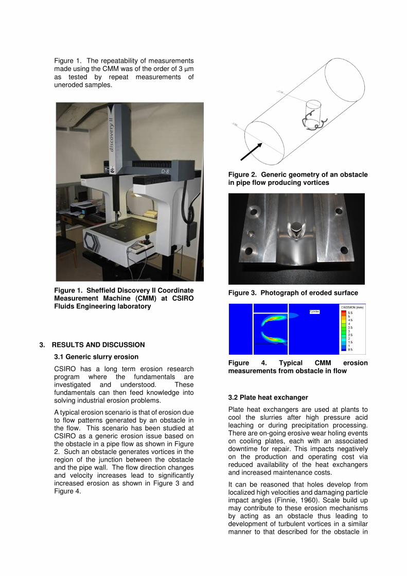
Figure 1. The repeatability of measurements made using the CMM was of the order of 3 μm
as tested by repeat measurements of uneroded samples.
Figure 1. Sheffield Discovery II Coordinate Measurement Machine (CMM) at CSIRO Fluids Engineering laboratory
3. RESULTS AND DISCUSSION
3.1 Generic slurry erosion
CSIRO has a long term erosion research program where the fundamentals are investigated and understood. These fundamentals can then feed knowledge into solving industrial erosion problems.
A typical erosion scenario is that of erosion due to flow patterns generated by an obstacle in the flow. This scenario has been studied at CSIRO as a generic erosion issue based on the obstacle in a pipe flow as shown in Figure 2. Such an obstacle generates vortices in the region of the junction between the obstacle and the pipe wall. The flow direction changes and velocity increases lead to significantly increased erosion as shown in Figure 3 and Figure 4.
Figure 2. Generic geometry of an obstacle in pipe flow producing vortices
Figure 3. Photograph of eroded surface
Figure 4. Typical CMM erosion measurements from obstacle in flow
3.2 Plate heat exchanger
Plate heat exchangers are used at plants to cool the slurries after high pressure acid leaching or during precipitation processing. There are on-going erosive wear holing events on cooling plates, each with an associated downtime for repair. This impacts negatively on the production and operating cost via reduced availability of the heat exchangers and increased maintenance costs.
It can be reasoned that holes develop from localized high velocities and damaging particle impact angles (Finnie, 1960). Scale build up may contribute to these erosion mechanisms by acting as an obstacle thus leading to development of turbulent vortices in a similar manner to that described for the obstacle in

pipe flow as above. Wear repairs (such as uneven weld deposits) can cause a similar effect as shown by Wong et al. (2015). A model of a segment of the heat exchanger was constructed and set up at CSIRO in a slurry flow loop as shown in Figure 5 and Figure 6.
Figure 5. View of plate heat exchanger model
Figure 6. Heat exchanger model installed in slurry loop
Erosion measurements were made over both upper and under surfaces of the model cooling plates as schematically illustrated in Figure 7. Erosion mapping was at 1 mm intervals over a rectangular grid as shown in the figures.
(a) Under surface
(b) Upper surface
Figure 7. Erosion measurement schematic: (a) under surface, (b) upper
surface
Erosion results from experiment are shown in Figure 8.
Figure 8. CMM measurement results on heat exchanger plates (same scale): (a)
under surface, (b) upper surface
It can be seen that at the apex of the triangle that the maximum erosion is of the order of 0.21 mm and at the base of the triangle is approximately 0.06 mm. It is understood that these locations are similar to the erosion observed in full scale. The corresponding peak erosion is an order of magnitude higher (approximately 20-100 times) than the
Flow
Flow
Flow
Flow

background wear downstream of the leading area of the plate.
In terms of erosion mitigation, it is desirable to do one or more of the following:
• Reduce flow velocity
• Reduce flow disturbances
• Move flow disturbances from vulnerable surfaces to free stream areas
• Homogenise the velocity field as much as possible.
For the heat exchanger, an insert was devised which placed the flow disturbance upstream of the heat exchanger plates. This design modification was found to reduce the peak erosion by ~90-99% in tests, anticipated to achieve a service life similar to the average cooling plate (away from the erosive hot spots). This design did not increase wear in the downstream location; the bulk of the cooling plate pack. Further work is continuing in this area to improve the practicality of the erosion solution for the full scale implementation.
3.3 PD pump discharge accumulator
A test tank at CSIRO Fluids Engineering laboratory (Melbourne) was set up geometrically similar to the discharge accumulators at RTA Yarwun for the Wirth pumps as shown in Figure 9. The model test tank diameter is 0.390m. Water flow was re-circulated through the test tank, mimicking the full-scale slurry flow discharged from the Wirth pump.
Figure 9. Experimental model accumulator at CSIRO Melbourne
Tracer polystyrene beads (with SG~1.) were released into the tank to visualize the flow pattern during the laboratory observation
studies. Glass beads (~5 mm in size) were used to model coarse particles. Videos were taken to record the flow patterns.
It was observed that there was a strong vortex spinning below the inlet and exit pipes with the existing design, as illustrated in Figure 10. Coarse particles such as glass beads (~5mm) used in the laboratory were found to be trapped in the vortex. It could be seen that these particles were spinning along the vessel bottom (dome-shaped) under the action of the vortex. It is thought that spinning of the coarse solids at the vessel bottom would produce a drilling effect to cause erosion damage similar to that reported by Brown (2002). The location of this vortex “drilling” point appears to correspond well with the erosion damage reported at the site (Figure 10).
Figure 10. Vortex pattern, sketched based on observation
To solve the problem, attempts were made to suppress the vortex by installing baffle inserts. An optimum design of vortex breaker was developed based on a trial of various ideas (a total of 6 modifications were tested).
3.4 Flash vessels
A test rig was set up in order to simulate the erosive conditions expected under flashing conditions, particularly on the riser caps, in particular a swirl flow version. A geometrically scaled down model flash vessel with diameter of 0.390 m was set up using components made at CSIRO. An agitated slurry holding tank
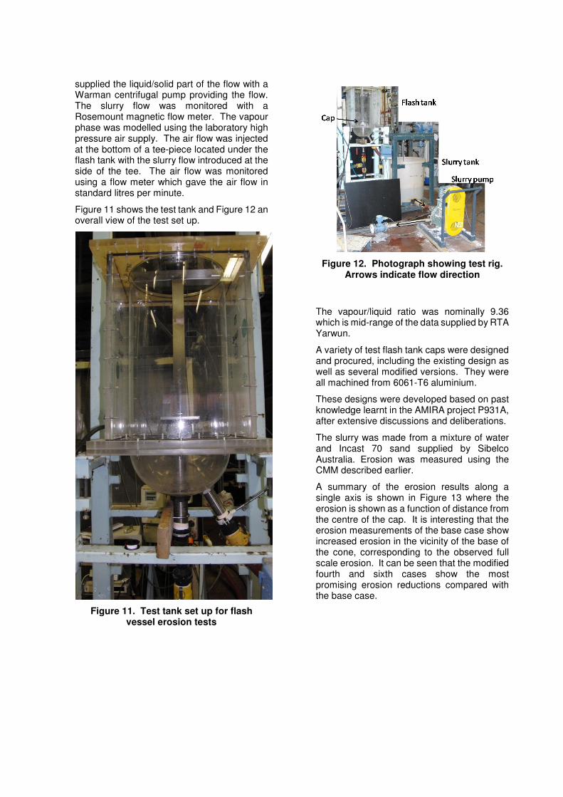
supplied the liquid/solid part of the flow with a Warman centrifugal pump providing the flow. The slurry flow was monitored with a Rosemount magnetic flow meter. The vapour phase was modelled using the laboratory high pressure air supply. The air flow was injected at the bottom of a tee-piece located under the flash tank with the slurry flow introduced at the side of the tee. The air flow was monitored using a flow meter which gave the air flow in standard litres per minute.
Figure 11 shows the test tank and Figure 12 an overall view of the test set up.
Figure 11. Test tank set up for flash vessel erosion tests
Figure 12. Photograph showing test rig. Arrows indicate flow direction
The vapour/liquid ratio was nominally 9.36 which is mid-range of the data supplied by RTA Yarwun.
A variety of test flash tank caps were designed and procured, including the existing design as well as several modified versions. They were all machined from 6061-T6 aluminium.
These designs were developed based on past knowledge learnt in the AMIRA project P931A, after extensive discussions and deliberations.
The slurry was made from a mixture of water and Incast 70 sand supplied by Sibelco Australia. Erosion was measured using the CMM described earlier.
A summary of the erosion results along a single axis is shown in Figure 13 where the erosion is shown as a function of distance from the centre of the cap. It is interesting that the erosion measurements of the base case show increased erosion in the vicinity of the base of the cone, corresponding to the observed full scale erosion. It can be seen that the modified fourth and sixth cases show the most promising erosion reductions compared with the base case.

Figure 13. Summary of erosion tests over all geometries tested
Observations also showed that there was no significant sedimentation in the tank for any of the caps tested.
It can be concluded that Modified 6 case can be considered as an optimum design modification for reducing the swirler cap erosion. It is hypothesized that this design works due to some accumulation of liquid/sands in the cavity under the centrifugal effect as the air/slurry from the riser flow is redirected by the cap. The accumulated solids/liquid material protects the cap surface from impact from the solids, reducing the erosion damage.
4. CONCLUSION
CSIRO Fluids Engineering has a long term program of both fundamental and applied erosion research, with the ultimate aim of reducing erosion of mineral processing equipment.
Examples include:
o Applying an insert to reduce erosion in plate heat exchangers
o Disrupting an erosive vortex in a PD pump accumulator
o Reducing erosion in flash tank caps
In each of these cases, changes to the geometry and hence the fluid dynamics, were shown to be effective in reducing the erosion.
5. REFERENCES
Brown, G.J., 2002. Erosion prediction in slurry pipeline tee-junctions. Appl Math Model, 26(2): 155-170. Finnie, I., 1960. Erosion of surface by solid particles. Wear, 3: 87-103.
Graham, L.J.W., Lester, D.R. and Wu, J., 2010. Quantification of erosion distributions in complex geometries. Wear, 268(9-10): 1066-1071. Simpson, R.L., 2001. Junction flows. Annu. Rev. Fluid Mech., 33: 415-443. Wong, C.Y., Solnordal, C., Graham, L., Short, G. and Wu, J., 2015. Slurry erosion of surface imperfections in pipeline systems. Wear, 336–337: 72-85.
6. ACKNOWLEDGEMENTS
The authors are grateful for the support of the various industrial clients both within the alumina industry and elsewhere who have supported the erosion research at CSIRO.