Embed Size (px)
Citation preview

Voice CardsReference Guide
Publication 2008–VRevision A0
IMACS SystemRelease 5.1.6April 2003
Model No.Running Head
Trademarks:5ESS is a registered trademark of Lucent TechnologiesDMS-100 and DMS-200 are trademarks of Northern Telecom.Nortel is a trademark of Northern TelecomElectronic Business Sets, Meridian Digital Centrex are registered trademarks of NortelHyperTerminal is a registered trademark of MicrosoftPremisys is a registered trademark of Premisys Communications, Inc.SLC is a registered trademark of Lucent TechnologiesWindows 3.1 and 95 are registered trademarks of Microsoft
All other trademarks and registered trademarks are the property of their respective holders.
FCC Registration number:1H5SNG-73866-DD-E (integral CSU)B468NR-68618-DM-E (internal modem)
Canadian Certification Number: 1932 5217 ACanadian DOC Load number: 5
Ringer Equivalence Number: 0.2A (internal modem)
Approvals: UL listed to UL# 1459 Second Edition, Third EditionCSA listed to C22.2 No. 950-M89
COPYRIGHT © 1992-2003 Premisys Communications, Inc. All rights reserved.
This publication is protected by federal and international copyright law. No part of this publication may be copied or distributed, transmitted, transcribed, stored in a retrieval system, or translated into any human or computer language in any form or by any means, electronic, mechanical, magnetic, manual or otherwise, or disclosed to third parties without the express written permission from the manufacturer.
The manufacturer makes no representation or warranties with respect to the contents hereof and specifically disclaims any implied warranties of merchantability or fitness for a particular purpose. Further, the manufacturer reserves the right to revise this publication and to make changes from time to time in the contents hereof without obligation from the manufacturer to notify any person of such revision or changes.
Product Description
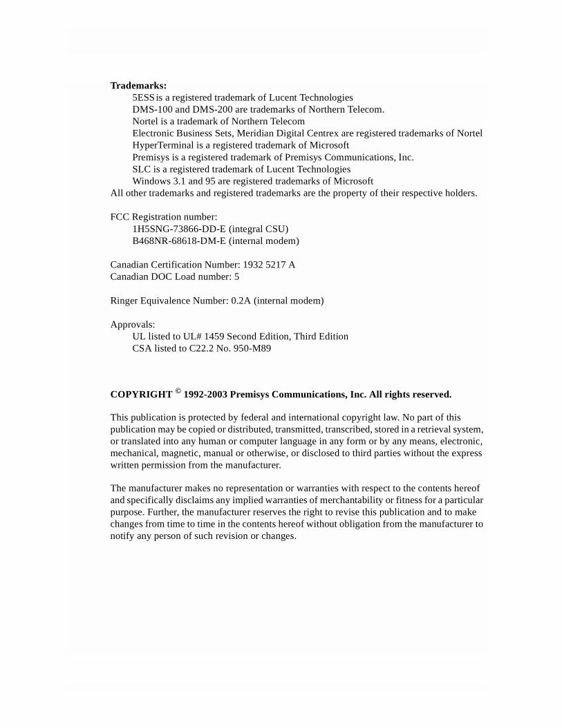
The Voice Cards provide an interface between voice circuits and a digital network.Voice interface cards are intended for short loop applications that require high port densities.
This integrated access system offers voice cards that support E&M, FXS, FXO, FXS Coin, FXO Coin and P-Phone interfaces.
Voice Cards
• E&M E&M 2W*8 (810860), E&M-LB 4W*8 (811760), E&M 4W*8 (811960)
E&M 2W*4-6 (8104), E&M 4W*2-6 (8812), E&M Wx2ER (8113)
E&M 4W*4-6 (8114), E&M 4W*ER (8115), E&M 4W*8-6 (8118)
• FXS FXS 2W*8-6 (812960)
FXS 2W*2-9 (8122), FXS 2W*2-6 (8123), FXS 2W*4-9 (8124)
FXS 2W*4-6 (8125), FXS 2W*8-9 (8128)
• FXO FXO 2W*8-6 (813960, 813970)
FXO 2W*2-9 (8132), FXO 2W*2-6 (8133),
FXO 2W*4-9 (8134), FXO 2W*4-6 (8135),
FXO 2W*8-9 (8138)
• FXS-C FXS-C 2W*8-6 (814960)
FXS-C 6-900 (8148)
• FXO-C FXO-C 2W*8-6 (815960)
FXO-C 8-900 (8158)
• LBVR LBVR-8 Fax (830060)
• P-Phone PPO (813160), PPS (812160)
Note: Cards listed in italics have been Manufacturing Discontinued (MD), but are supported under this product host code for backward compatibility.
Model No.Running Head
Using this Voice Card Reference Guide
This Voice Card Reference Guide provides technicians with switch settings, connector pinouts, configuration, and troubleshooting information for the voice cards.
Chapter 1. E&M Card
Chapter 2. FXS Card
Chapter 3. FXO Card
Contents
Contents
Chapter 1 E&M Card
1.1 Introduction ....................................................................................................1-11.2 E&M Card Descriptions .................................................................................1-11.2.1 E&M 2W*8 Card Description (810860) ....................................................1-11.2.1.1 Card Switch Settings ..............................................................................1-11.2.1.2 Installing the E&M 2W*8 Card .............................................................1-31.2.2 E&M 4W*8 ER Card Description (811960) ..............................................1-41.2.2.1 Card Jumper/Switch Settings .................................................................1-41.2.2.2 Installing the E&M 4W*8 ER Card .......................................................1-41.3 E&M Card User Screens and Settings ...........................................................1-41.3.1 E&M Card Main Screen .............................................................................1-41.3.2 Test Screen ...............................................................................................1-101.3.3 Loopback Screen ......................................................................................1-151.4 E&M Card Error Messages ..........................................................................1-161.4.1 E&M Card Troubleshooting.....................................................................1-161.5 E&M Card Specifications ............................................................................1-17
Chapter 2 FXS Card
2.1 Introduction ....................................................................................................2-12.2 FXS Card Descriptions ...................................................................................2-22.2.1 FXS 2W*8-6 Card Description (812960)...................................................2-22.2.1.1 Card Jumper/Switch Settings .................................................................2-22.2.1.2 Installing the Card ..................................................................................2-32.3 FXS Card User Screens and Settings .............................................................2-42.3.1 FXS Card Main Screen...............................................................................2-42.3.2 Test Screen ...............................................................................................2-132.4 FXS Error Messages .....................................................................................2-182.5 FXS Card Troubleshooting ..........................................................................2-182.6 FXS Card Specifications ..............................................................................2-19
Chapter 3 FXO Card
3.1 Introduction ....................................................................................................3-13.2 FXO Card Descriptions ..................................................................................3-23.2.1 FXO 2W*8-6 Card Description (813970) ..................................................3-23.2.1.1 Card Jumper/Switch Settings .................................................................3-23.2.1.2 Installing the Card ..................................................................................3-33.3 FXO Card User Screens and Settings ............................................................3-43.3.1 FXO Card Main Screen ..............................................................................3-4
Voice Cards IMACS System Release 5.1.6 i
Model No.Running HeadContents
3.3.2 Test Screen............................................................................................... 3-113.4 FXO Card Error Messages .......................................................................... 3-163.5 FXO Card Troubleshooting ......................................................................... 3-163.6 FXO Card Specifications ............................................................................. 3-17
ii IMACS System Release 5.1.6 Voice Cards
Figures
Figures
1-1 Typical E&M Card Switches ...............................................................................................1-21-2 Typical E&M Card Main Screen .........................................................................................1-51-3 E&M Card Loopbacks .........................................................................................................1-91-4 Typical E&M Card Test Screen.........................................................................................1-111-5 Typical E&M Loopback Screen ........................................................................................1-152-1 FXS 2W*8-6 Card Jumpers Settings ...................................................................................2-32-2 Typical FXS Card Main Screen...........................................................................................2-42-3 FXS Card Loopbacks.........................................................................................................2-112-4 Typical FXS Card Test Screen ..........................................................................................2-143-1 FXO 2W*8-6 Card Jumper Settings ....................................................................................3-33-2 Typical FXO Card Main Screen ..........................................................................................3-43-3 FXO Card Loopbacks ..........................................................................................................3-93-4 Typical FXO Card Test Screen..........................................................................................3-12
Voice Cards IMACS System Release 5.1.6 iii

Model No.Running HeadFigures
iv IMACS System Release 5.1.6 Voice Cards
Tables
Tables
1-1 Typical E&M Card Switch Definitions ..............................................................................1-31-2 Typical E&M Card Switch Settings ...................................................................................1-31-3 Main Screen Actions .........................................................................................................1-51-4 Main Screen Option Settings and Defaults........................................................................1-61-5 Test Screen Actions .........................................................................................................1-111-6 Test Screen Option Settings and Defaults .......................................................................1-111-7 Status Information Field Settings ....................................................................................1-141-8 Loopback Screen of Actions............................................................................................1-151-9 Loopback Screen Option Settings and Defaults ..............................................................1-162-1 Main Screen Actions .........................................................................................................2-42-2 Main Screen Option Settings and Defaults.........................................................................2-52-3 Incoming Calls (ls-R2e).....................................................................................................2-82-4 Outgoing Calls (ls-R2e).....................................................................................................2-82-5 Incoming Calls (R1.5i) ......................................................................................................2-92-6 Outgoing Calls (R1.5o)......................................................................................................2-92-7 Test Screen Actions .........................................................................................................2-142-8 Test Screen Option Settings and Defaults ........................................................................2-142-9 Status Information Field Settings ....................................................................................2-173-1 Main Screen Actions .........................................................................................................3-43-2 Main Screen Option Settings and Defaults........................................................................3-53-3 Test Screen Actions ..........................................................................................................3-123-4 Test Screen Option Settings and Defaults ........................................................................3-123-5 Status Information Field Settings ....................................................................................3-15
Voice Cards IMACS System Release 5.1.6 v

Model No.Running HeadTables
vi IMACS System Release 5.1.6 Voice Cards

Chapter 1E&M Card
1.1 Introduction
This chapter provides switch settings, connector pinouts, configuration, and troubleshooting information for the E&M Voice Cards. These cards are identified as the E&M 2W*8 (810860), E&M 4W*8 (811960), and on their faceplate ejectors.
The E&M cards manage the flow of toll-grade voice traffic through the Integrated Access System. Each card encodes an analog (voice, VF) signal to a digital bitstream at the local Integrated Access System for transmission over a T1 or E1 network. Each card also decodes the digital signal to analog at the remote system. Both cards support E&M signaling types I, II, IV, and V.
Each card connects to eight CPE voice circuits from a PBX or other user facility. Normal E&M, Transmission-Only, and E&M R2 signaling are supported. The E&M cards also can use the voice compression features of an ADPCM card.
1.2 E&M Card Descriptions
1.2.1 E&M 2W*8 Card Description (810860)
The E&M 2W*8 card has eight voice ports, each with 600-ohm terminating impedance.
Notice!
UL STATEMENT
OPERATION OF THIS INTERFACE IS LIMITED TO INTRA-BUILDING CONNECTIONS ONLY
1.2.1.1 Card Switch Settings
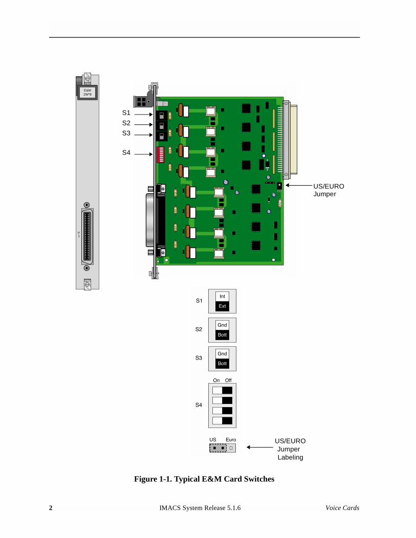
The E&M 2W*8 card has four switches (S1 through S4) that you must set before inserting the card into the chassis. These switches establish the type of E&M the card will use on all eight ports. Figure 1-1 shows these switches, Table 1-1 defines their purposes, and Table 1-2 lists the settings for each signaling type.
Voice Cards IMACS System Release 5.1.6 1
Model No.Running Head
Figure 1-1. Typical E&M Card Switches
E&M2W*8
P1
US/EUROJumper
JumperUS/EURO
Labeling
S4
S3
S1
S2
2 IMACS System Release 5.1.6 Voice Cards
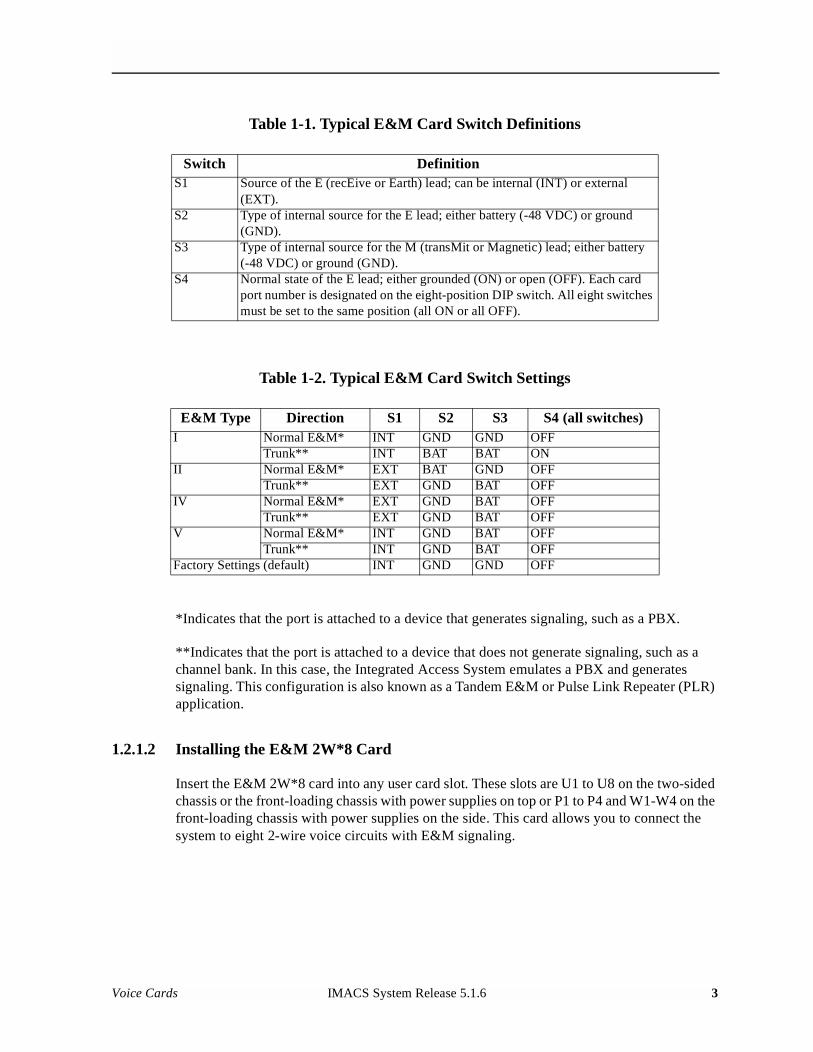
Table 1-1. Typical E&M Card Switch Definitions
Table 1-2. Typical E&M Card Switch Settings
*Indicates that the port is attached to a device that generates signaling, such as a PBX.
**Indicates that the port is attached to a device that does not generate signaling, such as a channel bank. In this case, the Integrated Access System emulates a PBX and generates signaling. This configuration is also known as a Tandem E&M or Pulse Link Repeater (PLR) application.
1.2.1.2 Installing the E&M 2W*8 Card
Insert the E&M 2W*8 card into any user card slot. These slots are U1 to U8 on the two-sided chassis or the front-loading chassis with power supplies on top or P1 to P4 and W1-W4 on the front-loading chassis with power supplies on the side. This card allows you to connect the system to eight 2-wire voice circuits with E&M signaling.
Switch DefinitionS1 Source of the E (recEive or Earth) lead; can be internal (INT) or external
(EXT).S2 Type of internal source for the E lead; either battery (-48 VDC) or ground
(GND).S3 Type of internal source for the M (transMit or Magnetic) lead; either battery
(-48 VDC) or ground (GND).S4 Normal state of the E lead; either grounded (ON) or open (OFF). Each card
port number is designated on the eight-position DIP switch. All eight switches must be set to the same position (all ON or all OFF).
E&M Type Direction S1 S2 S3 S4 (all switches)I Normal E&M* INT GND GND OFF
Trunk** INT BAT BAT ONII Normal E&M* EXT BAT GND OFF
Trunk** EXT GND BAT OFFIV Normal E&M* EXT GND BAT OFF
Trunk** EXT GND BAT OFFV Normal E&M* INT GND BAT OFF
Trunk** INT GND BAT OFFFactory Settings (default) INT GND GND OFF
Voice Cards IMACS System Release 5.1.6 3
Model No.Running Head
1.2.2 E&M 4W*8 ER Card Description (811960)
The E&M 4W*8 ER card provides an extended transmit TLP range (-17.5 to +14.5 dB) for dedicated 4-wire modem applications. This range is required for data speeds of 19.2 kbps and higher.
Notice!
UL STATEMENT
OPERATION OF THIS INTERFACE IS LIMITED TO INTRA-BUILDING CONNECTIONS ONLY
1.2.2.1 Card Jumper/Switch Settings
The E&M 4W*8 card has four switches (S1 through S4) that you must set before inserting the card into the chassis. These switches establish the type of E&M the card will use on all eight ports. Figure 1-1 shows these switches, Table 1-1 defines their purposes, and Table 1-2 lists the settings for each signaling type.
1.2.2.2 Installing the E&M 4W*8 ER Card
Insert the E&M 4W*8 card into any user card slot. These slots are U1 to U8 on the two-sided chassis or the front-loading chassis with power supplies on top or P1 to P4 and W1-W4 on the front-loading chassis with power supplies on the side. This card allows you to connect the system to eight 4-wire voice circuits with E&M signaling.
1.3 E&M Card User Screens and Settings
1.3.1 E&M Card Main Screen
You must configure the E&M card for operation after installing it in the system chassis. This is done from the E&M Main Card Screen, which is shown in Figure 1-2. To go to that screen, highlight the desired card on the System Main Screen, then press <Enter>. The E&M Card Main Screen shows numerous columns of settings, each for one port of the card.
4 IMACS System Release 5.1.6 Voice Cards
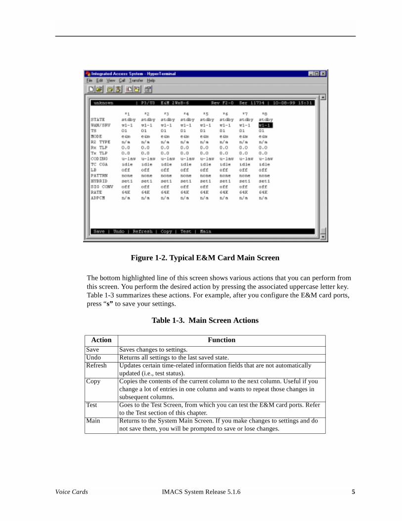
Figure 1-2. Typical E&M Card Main Screen
The bottom highlighted line of this screen shows various actions that you can perform from this screen. You perform the desired action by pressing the associated uppercase letter key. Table 1-3 summarizes these actions. For example, after you configure the E&M card ports, press “s” to save your settings.
Table 1-3. Main Screen Actions
Action FunctionSave Saves changes to settings.Undo Returns all settings to the last saved state.Refresh Updates certain time-related information fields that are not automatically
updated (i.e., test status).Copy Copies the contents of the current column to the next column. Useful if you
change a lot of entries in one column and wants to repeat those changes in subsequent columns.
Test Goes to the Test Screen, from which you can test the E&M card ports. Refer to the Test section of this chapter.
Main Returns to the System Main Screen. If you make changes to settings and do not save them, you will be prompted to save or lose changes.
Voice Cards IMACS System Release 5.1.6 5

Model No.Running Head
Table 1-4 summarizes the configuration settings for the E&M card, along with the available and factory-default option settings. The parameters and settings are also described in the following paragraphs.
Table 1-4. Main Screen Option Settings and Defaults
Notes:
1. Choosing wan allows you to choose a WAN port (w1-1 through w4-2). Choosing serv lets you choose an ATM or FRS server card in slot P1, P2, or P3, followed by a logical port on that card. The user option is not used. See the WAN/SRV paragraph that follows.
2. Time slot 16 is not available if the port is assigned to an E1 WAN link whose time slot 16 is programmed for cas or ccs.
3. The default is sl-1 if the Mode is set to e&mR2 or R2mod.
4. The extended setting range for the 8119 card is from -16.3 to +7.5 dB.
5. The default coding is a-inv for E1 and u-law for T1.
Choosing a Rate other than 64K allows you to select an ADPCM slot.
STATE
The State setting determines whether the port is active or inactive. An inactive port does not occupy a time slot on a WAN link. Set this field to stdby (standby) for ports that will not be used or that are not yet configured. Or, set it to actv (active) for ports that are ready for use.
Parameter User Options Notes DefaultSTATE stdby actv stdbyWAN/SRV none wan serv user 1 w1-1TS 01-24 01-31 2 01MODE e&m to e&mR2 R2mod e&mR2 TYPE n/a (when MODE is set to e&mR2 or R2mod the default is s1-1) 3 n/aRx TLP -16.3 dB to +7.5 dB 0Tx TLP -16.3 dB to +7.5 dB 4 0CODING u-law a-law a-inv 5 u-lawTC CGA idle busy idleLB off dgtl anlg offPATTRN none D-mW quiet noneHYBRID n/a set1 to set8 user n/aSIG CONV off on offRATE 64K 24K,1 32K,1 40K,1 24K,2 32K,2 40K,2 64KADPCM n/a P1 P2 P3 n/a
6 IMACS System Release 5.1.6 Voice Cards
WAN/SRV
The WAN/SRV setting identifies the WAN link or server card assigned to this port. If you choose wan, you also must select the desired port (w1-1 through w4-2) of a WAN card for transmission over a T1 or E1 link. Or, choose serv to assign the card port to a server card in the system. This can be an ATM or FRS card, which resides in chassis slot P1, P2, or P3. You must then choose a logical port on that card. The user option is not used.
It is not necessary to assign all ports of the same E&M card to the same WAN link or server card, or to contiguous time slots on a WAN link.
TS
The TS setting identifies the time slot on the WAN link to which this port is assigned. This value is from 1 to 24 for T1 links and 1 to 31 for E1 links. However, time slot 16 is not available for E1 links that are programmed for CAS or CCS signaling. For a display of available time slots, refer to the cross-connect map for the WAN link selected.
MODE
The Mode setting specifies whether or not a port uses E&M signaling, or if it operates in the Transmission-Only (TO) mode. Use the to mode if you are connecting the port to a four-wire, dedicated-line modem that does not require E&M signaling. The signaling type for all eight ports of an E&M card is defined by setting hardware switches S1 through S4 as described earlier in this chapter. Select e&m for standard Type I, II, IV, or V signaling. Select e&mR2 for symmetrical R2 signaling for calls originating from either the digital or analog side. The R2mod setting provides modified R2 signaling for Motorola paging terminal equipment.
R2 TYPE
The R2 Type setting is set to n/a when the Mode is set to e&m or to. The signaling type for all eight E&M ports is established by setting hardware switches S1 through S4 as described earlier. If the Mode selected for the port is e&mR2 or R2mod, the R2 Type automatically defaults to sl-1.
Rx TLP
The Receive Transmission Level Point (TLP) setting controls the amount of gain or loss added to a signal after it is decoded to analog. To increase the signal level, set the Rx TLP field to a positive number (i.e., the larger the number, the more gain is added). To decrease the signal level, set the Rx TLP field to a negative number (i.e., the more negative the number, the more the signal level is decreased). For example, an incoming signal at -5 dBm can be increased to -2 dBm by setting Rx TLP to +3 dB. The Rx TLP range is -16.3 dB to +7.5 dB.
Voice Cards IMACS System Release 5.1.6 7
Model No.Running Head
Tx TLP
The Transmit TLP setting controls the amount of gain or loss added to the voice signal coming in from the local CPE before it is encoded to digital PCM. To increase the incoming signal level, set the Tx TLP field to a negative value (i.e., the more negative the number, the more gain is added). To decrease the signal level, set the Tx TLP setting to a positive number (i.e., the more positive the number, the more the signal level is decreased). For example, an incoming signal at -16 dBm can be increased to 0 dBm by setting Tx TLP to -16 dB. For the E&M 4W*8 Card, the Tx TLP range is -16.5 dB to +7.3 dB. For the E&M 4W*8 ER E&M Card, this range is -17.5 dB to +14.5 dB.
CODING
The Coding field sets the PCM companding (coding) method used for a port. Generally, the North American T1 environment uses u-law (mu-law) coding, and the International E1 environment uses either a-law or a-inv (inverted A-law) coding. The a-inv setting provides a higher ones density on an E1 line than a-law. The coding default setting is defined by the type of associated WAN card.
TC CGA
The Trunk Conditioning during Carrier Group Alarm setting defines whether the E&M card port should be placed in the idle or busy mode upon declaration of a Carrier Group Alarm (CGA) on the WAN link to which the port is assigned. The TC CGA setting has no effect on Transmission-Only circuits, for which the to signaling mode is used.
In most cases, you should set this parameter to busy. If a call is in progress when the CGA alarm is received, the system holds the call for two seconds, drops it, and then busies out the port to the attached PBX for the duration of the alarm. Once the alarm clears, the system automatically places the port back in the idle mode, thereby making it available to the attached PBX.
LB
The LB setting allows you to loop a port back toward the network and far end for testing and troubleshooting. Figure 1-3 shows the available loopbacks. The dgtl (digital) loopback sends the incoming digital signal from the network back toward the far end, without decoding it. The anlg (analog) loopback sends the decoded analog signal back to the far end. To disable either loopback after testing, set this field to off.
8 IMACS System Release 5.1.6 Voice Cards
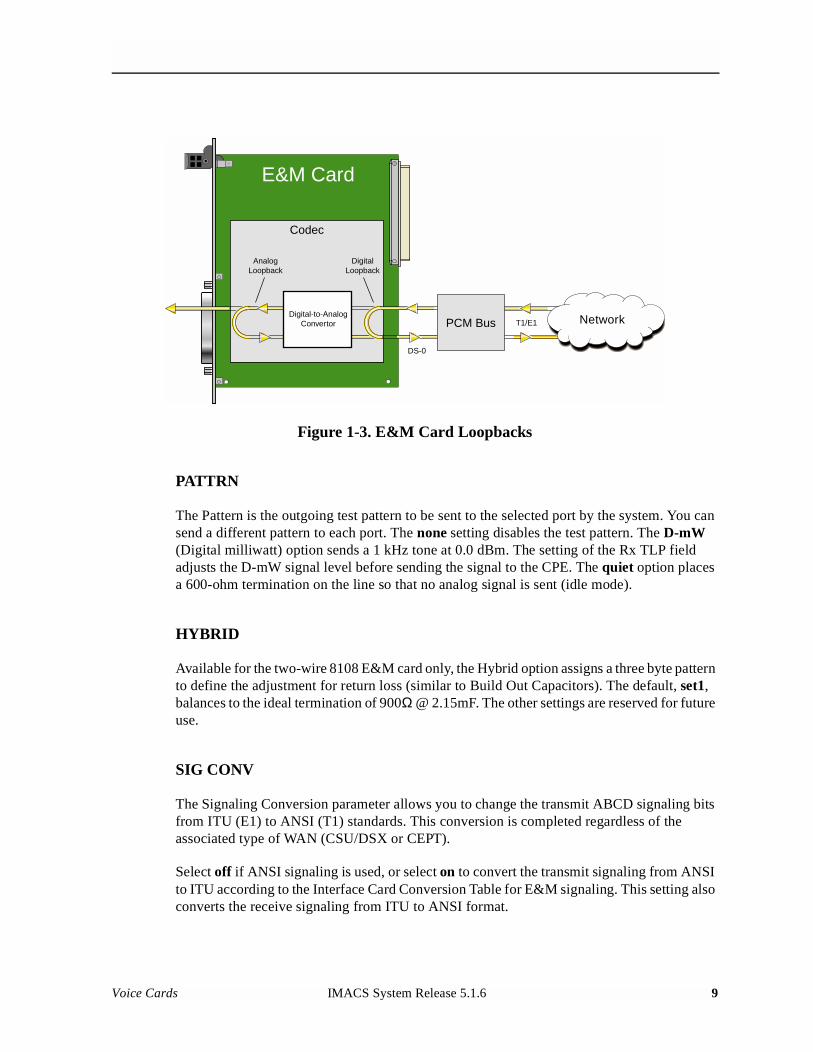
Figure 1-3. E&M Card Loopbacks
PATTRN
The Pattern is the outgoing test pattern to be sent to the selected port by the system. You can send a different pattern to each port. The none setting disables the test pattern. The D-mW (Digital milliwatt) option sends a 1 kHz tone at 0.0 dBm. The setting of the Rx TLP field adjusts the D-mW signal level before sending the signal to the CPE. The quiet option places a 600-ohm termination on the line so that no analog signal is sent (idle mode).
HYBRID
Available for the two-wire 8108 E&M card only, the Hybrid option assigns a three byte pattern to define the adjustment for return loss (similar to Build Out Capacitors). The default, set1, balances to the ideal termination of 900Ω @ 2.15mF. The other settings are reserved for future use.
SIG CONV
The Signaling Conversion parameter allows you to change the transmit ABCD signaling bits from ITU (E1) to ANSI (T1) standards. This conversion is completed regardless of the associated type of WAN (CSU/DSX or CEPT).
Select off if ANSI signaling is used, or select on to convert the transmit signaling from ANSI to ITU according to the Interface Card Conversion Table for E&M signaling. This setting also converts the receive signaling from ITU to ANSI format.
Network
E&M Card
Codec
PCM BusDigital-to-Analog
Convertor
AnalogLoopback
DigitalLoopback
T1/E1
DS-0
Voice Cards IMACS System Release 5.1.6 9
Model No.Running Head
RATE
The Rate parameter allows you to use the voice compression capabilities of an ADPCM card. If that card is not present in the system, the Rate is set to 64k and cannot be changed. The 64k setting (default) is the normal encoding/decoding rate for voice circuits.
ADPCM voice channels are assigned in pairs by designating two voice ports (E&M, FXO or FXS) to the same WAN link and time slot, and then selecting rate settings for the pair that add up to 64 kbps. The following pairing combinations are possible:
24K,1+40K,2 (24 kb coding on one side of the time slot and 40 kb coding on the other side of the same time slot)
32K,1+32K,2 (32 kb encoding on each side of a time slot)
40K,1+24K,2 (40 kb coding on one side of the time slot and 24 kb coding on the other side)
Number 1 after the rate setting assigns that portion of the voice port pair to the odd side of the ADPCM pair. Number 2 after the rate setting assigns that portion of the voice port pair to the even side of the ADPCM pair.
For more information about voice port assignments to a time slot and ADPCM card.
ADPCM
The ADPCM parameter lets you assign the current port to an ADPCM card in the system. The default setting is n/a and only changes when a Rate smaller than 64k is selected (see above). You can then select which ADPCM card to use for the port (this assignment is made by chassis slot number). The options are slots P1, P2, and P3.
1.3.2 Test Screen
The Test Screen (Figure 1-4) facilitates testing and maintenance by allowing you to monitor and set the status of the analog signals and/or the A, B, C, and D signaling bits of all E&M circuits on the card. In cross-connect systems, the test option can also send test patterns and tones towards the CPE and network sides of the system.
The Test Screen also shows the signaling type assigned to the card via the switch settings described earlier.
10 IMACS System Release 5.1.6 Voice Cards
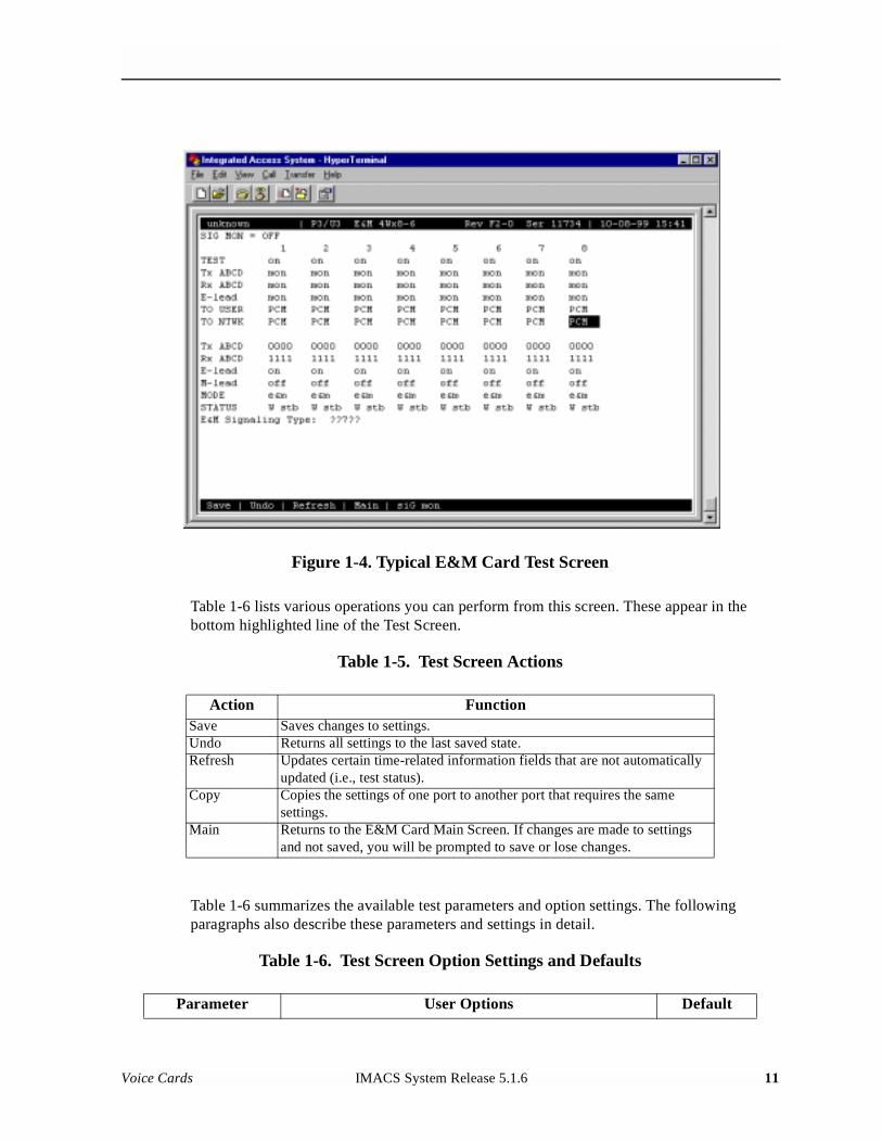
Figure 1-4. Typical E&M Card Test Screen
Table 1-6 lists various operations you can perform from this screen. These appear in the bottom highlighted line of the Test Screen.
Table 1-5. Test Screen Actions
Table 1-6 summarizes the available test parameters and option settings. The following paragraphs also describe these parameters and settings in detail.
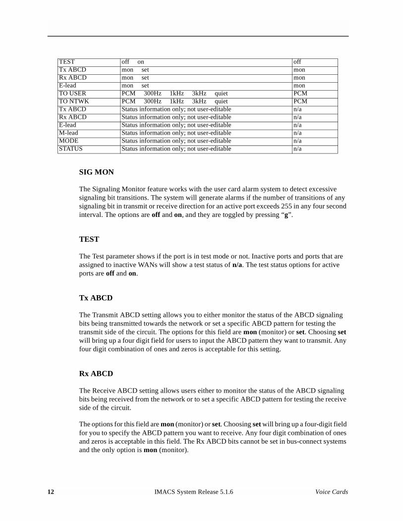
Table 1-6. Test Screen Option Settings and Defaults
Action FunctionSave Saves changes to settings.Undo Returns all settings to the last saved state.Refresh Updates certain time-related information fields that are not automatically
updated (i.e., test status).Copy Copies the settings of one port to another port that requires the same
settings.Main Returns to the E&M Card Main Screen. If changes are made to settings
and not saved, you will be prompted to save or lose changes.
Parameter User Options Default
Voice Cards IMACS System Release 5.1.6 11
Model No.Running Head
SIG MON
The Signaling Monitor feature works with the user card alarm system to detect excessive signaling bit transitions. The system will generate alarms if the number of transitions of any signaling bit in transmit or receive direction for an active port exceeds 255 in any four second interval. The options are off and on, and they are toggled by pressing “g”.
TEST
The Test parameter shows if the port is in test mode or not. Inactive ports and ports that are assigned to inactive WANs will show a test status of n/a. The test status options for active ports are off and on.
Tx ABCD
The Transmit ABCD setting allows you to either monitor the status of the ABCD signaling bits being transmitted towards the network or set a specific ABCD pattern for testing the transmit side of the circuit. The options for this field are mon (monitor) or set. Choosing set will bring up a four digit field for users to input the ABCD pattern they want to transmit. Any four digit combination of ones and zeros is acceptable for this setting.
Rx ABCD
The Receive ABCD setting allows users either to monitor the status of the ABCD signaling bits being received from the network or to set a specific ABCD pattern for testing the receive side of the circuit.
The options for this field are mon (monitor) or set. Choosing set will bring up a four-digit field for you to specify the ABCD pattern you want to receive. Any four digit combination of ones and zeros is acceptable in this field. The Rx ABCD bits cannot be set in bus-connect systems and the only option is mon (monitor).
TEST off on offTx ABCD mon set monRx ABCD mon set monE-lead mon set monTO USER PCM 300Hz 1kHz 3kHz quiet PCMTO NTWK PCM 300Hz 1kHz 3kHz quiet PCMTx ABCD Status information only; not user-editable n/aRx ABCD Status information only; not user-editable n/aE-lead Status information only; not user-editable n/aM-lead Status information only; not user-editable n/aMODE Status information only; not user-editable n/aSTATUS Status information only; not user-editable n/a
12 IMACS System Release 5.1.6 Voice Cards
E LEAD
The E-lead setting allows you to either monitor or set the E-lead state. The options for this field are mon (monitor) or set. Choosing set will bring up the options off (which drops the E lead) and on (which raises the E lead).
TO USER
In cross-connect systems only, the To User parameter allows you to break the circuit and send a test tone toward the user side of the system. The options for this field are PCM, 300Hz, 1 kHz, 3 kHz and quiet. Selecting PCM causes the PCM signal received from the network to continue to be sent to the user port in the normal manner.
This parameter is not supported in bus-connect systems and will always appear as n/a.
TO NTWK
In cross-connect systems only, the To Network parameter allows you to break the circuit and send a test tone toward the network side of the system. The options for this field are PCM, 300Hz, 1 kHz, 3 kHz and quiet. Selecting PCM causes the PCM signal received from the user port to continue to be sent to the network in the normal manner.
This parameter is not supported in bus-connect systems and will always appear as n/a.
Tx ABCD
The Transmit ABCD information field shows the current values of the ABCD bits that are being transmitted to the network. If TX ABCD in the top half of the screen is changed via the set function mentioned above, and the settings are saved by the Save command in the Test Screen, the new bit pattern chosen will be reflected here.
Rx ABCD
The Receive ABCD information field shows the current values of the ABCD signaling bits that are received from the network. If RX ABCD in the top half of the screen is changed via the set function mentioned above, and the settings are saved by the Save command in the Test Screen, the new bit pattern chosen will be reflected here.
E-Lead
The E-lead information field shows the current status of the E-lead of this port. The settings are either on or off.
Voice Cards IMACS System Release 5.1.6 13
Model No.Running Head
M-Lead
The M-lead information field shows the current status of the M-lead of this port. The settings are either on or off.
MODE
The Mode informational field shows the current mode of the port that was selected on the main E&M card screen. Valid settings are e&m, to, e&mR2, and R2mod.
STATUS
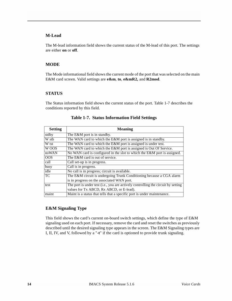
The Status information field shows the current status of the port. Table 1-7 describes the conditions reported by this field.
Table 1-7. Status Information Field Settings
E&M Signaling Type
This field shows the card’s current on-board switch settings, which define the type of E&M signaling used on each port. If necessary, remove the card and reset the switches as previously described until the desired signaling type appears in the screen. The E&M Signaling types are I, II, IV, and V, followed by a "-t" if the card is optioned to provide trunk signaling.
Setting Meaningstdby The E&M port is in standby.W stb The WAN card to which the E&M port is assigned is in standby.W tst The WAN card to which the E&M port is assigned is under test.W OOS The WAN card to which the E&M port is assigned is Out Of Service.noWAN No WAN card is configured in the slot to which the E&M port is assigned.OOS The E&M card is out of service.call Call set-up is in progress.busy Call is in progress.idle No call is in progress; circuit is available.TC The E&M circuit is undergoing Trunk Conditioning because a CGA alarm
is in progress on the associated WAN port.test The port is under test (i.e., you are actively controlling the circuit by setting
values for Tx ABCD, Rx ABCD, or E-lead).maint Maint is a status that tells that a specific port is under maintenance.
14 IMACS System Release 5.1.6 Voice Cards
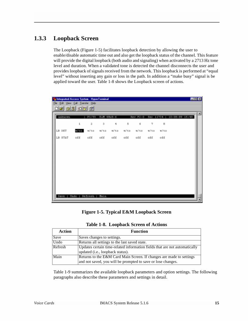
1.3.3 Loopback Screen
The Loopback (Figure 1-5) facilitates loopback detection by allowing the user to enable/disable automatic time out and also get the loopback status of the channel. This feature will provide the digital loopback (both audio and signaling) when activated by a 2713 Hz tone level and duration. When a validated tone is detected the channel disconnects the user and provides loopback of signals received from the network. This loopback is performed at “equal level” without inserting any gain or loss in the path. In addition a “make busy” signal is be applied toward the user. Table 1-8 shows the Loopback screen of actions.
Figure 1-5. Typical E&M Loopback Screen
Table 1-8. Loopback Screen of Actions
Table 1-9 summarizes the available loopback parameters and option settings. The following paragraphs also describe these parameters and settings in detail.
Action FunctionSave Saves changes to settings.Undo Returns all settings to the last saved state.Refresh Updates certain time-related information fields that are not automatically
updated (i.e., loopback status).Main Returns to the E&M Card Main Screen. If changes are made to settings
and not saved, you will be prompted to save or lose changes.
Voice Cards IMACS System Release 5.1.6 15
Model No.Running Head
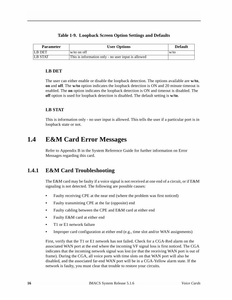
Table 1-9. Loopback Screen Option Settings and Defaults
LB DET
The user can either enable or disable the loopback detection. The options available are w/to, on and off. The w/to option indicates the loopback detection is ON and 20 minute timeout is enabled. The on option indicates the loopback detection is ON and timeout is disabled. The off option is used for loopback detection is disabled. The default setting is w/to.
LB STAT
This is information only - no user input is allowed. This tells the user if a particular port is in loopback state or not.
1.4 E&M Card Error Messages
Refer to Appendix B in the System Reference Guide for further information on Error Messages regarding this card.
1.4.1 E&M Card Troubleshooting
The E&M card may be faulty if a voice signal is not received at one end of a circuit, or if E&M signaling is not detected. The following are possible causes:
• Faulty receiving CPE at the near end (where the problem was first noticed)
• Faulty transmitting CPE at the far (opposite) end
• Faulty cabling between the CPE and E&M card at either end
• Faulty E&M card at either end
• T1 or E1 network failure
• Improper card configuration at either end (e.g., time slot and/or WAN assignments)
First, verify that the T1 or E1 network has not failed. Check for a CGA-Red alarm on the associated WAN port at the end where the incoming VF signal loss is first noticed. The CGA indicates that the incoming network signal was lost (or that the receiving WAN port is out of frame). During the CGA, all voice ports with time slots on that WAN port will also be disabled, and the associated far-end WAN port will be in a CGA-Yellow alarm state. If the network is faulty, you must clear that trouble to restore your circuits.
Parameter User Options DefaultLB DET w/to on off w/toLB STAT This is information only - no user input is allowed
16 IMACS System Release 5.1.6 Voice Cards
If the network is okay, verify that the proper WAN ports and time slots are assigned to the associated E&M voice ports at both ends, as previously outlined in this chapter. In a point-to-point network, the near-end and far-end E&M ports should both be assigned the same WAN port and time slot number. Also make sure the other parameters (such as the transmit and receive TLPs) are set properly at both ends.
If the E&M card port parameters are correct at both ends, and if the network is okay, the trouble is isolated to the E&M card or the associated port. Proceed as follows:
1. At the far end, activate an analog loopback on the E&M card port.
2. Send a 0 dBm (digital milliwatt) test signal toward the CPE at that end. That signal will be substituted for the normal signal coming from the far-end CPE; it will be sent back to the CPE at your end via the loopback path.
3. Check your CPE for this signal. If it is present, the far-end CPE or cabling to the far-end E&M card is probably faulty. Disable the loopback and test signal there, and fix the problem. If you still don’t receive a signal, go to step 4.
4. At your end, go to the E&M Card’s Main Screen and send a digital milliwatt test tone (0 dBm) toward the CPE. If you still don’t receive a signal, check the cabling from the E&M card to your CPE, and check the CPE itself. If those items are okay, replace the E&M card at your end.
5. If the E&M card is determined to be faulty, replace it and return the faulty unit for repair to the location specified by your distributor.
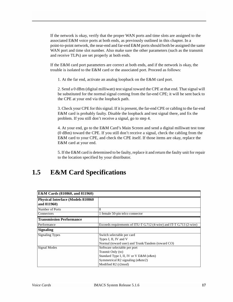
1.5 E&M Card Specifications
E&M Cards (810860, and 811960)
Physical Interface (Models 810860 and 811960)Number of Ports 8Connectors 1 female 50-pin telco connector
Transmission PerformancePerformance Exceeds requirements of ITU-T G.712 (4-wire) and IT-T G.713 (2-wire)
SignalingSignaling Types Switch selectable per card
Types I, II, IV and VNormal (toward user) and Trunk/Tandem (toward CO)
Signal Modes Software selectable per portTrasmit Only (to)Standard Type I, II, IV or V E&M (e&m)Symmetrical R2 signaling (e&mr2)Modified R2 (r2mod)
Voice Cards IMACS System Release 5.1.6 17
Model No.Running Head
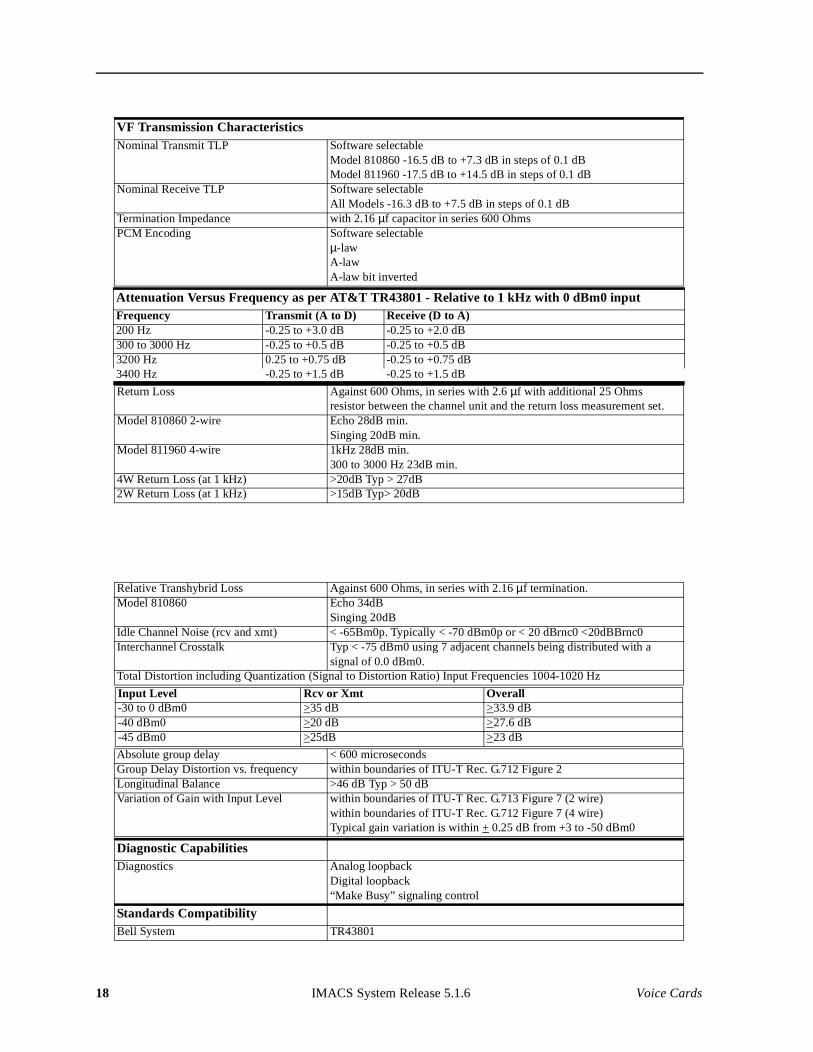
VF Transmission CharacteristicsNominal Transmit TLP Software selectable
Model 810860 -16.5 dB to +7.3 dB in steps of 0.1 dBModel 811960 -17.5 dB to +14.5 dB in steps of 0.1 dB
Nominal Receive TLP Software selectableAll Models -16.3 dB to +7.5 dB in steps of 0.1 dB
Termination Impedance with 2.16 µf capacitor in series 600 OhmsPCM Encoding Software selectable
µ-lawA-lawA-law bit inverted
Attenuation Versus Frequency as per AT&T TR43801 - Relative to 1 kHz with 0 dBm0 inputFrequency Transmit (A to D) Receive (D to A)200 Hz -0.25 to +3.0 dB -0.25 to +2.0 dB300 to 3000 Hz -0.25 to +0.5 dB -0.25 to +0.5 dB3200 Hz 0.25 to +0.75 dB -0.25 to +0.75 dB3400 Hz -0.25 to +1.5 dB -0.25 to +1.5 dB
Return Loss Against 600 Ohms, in series with 2.6 µf with additional 25 Ohms resistor between the channel unit and the return loss measurement set.
Model 810860 2-wire Echo 28dB min.Singing 20dB min.
Model 811960 4-wire 1kHz 28dB min.300 to 3000 Hz 23dB min.
4W Return Loss (at 1 kHz) >20dB Typ > 27dB2W Return Loss (at 1 kHz) >15dB Typ> 20dB
Relative Transhybrid Loss Against 600 Ohms, in series with 2.16 µf termination.Model 810860 Echo 34dB
Singing 20dBIdle Channel Noise (rcv and xmt) < -65Bm0p. Typically < -70 dBm0p or < 20 dBrnc0 <20dBBrnc0Interchannel Crosstalk Typ < -75 dBm0 using 7 adjacent channels being distributed with a
signal of 0.0 dBm0.Total Distortion including Quantization (Signal to Distortion Ratio) Input Frequencies 1004-1020 Hz
Input Level Rcv or Xmt Overall-30 to 0 dBm0 >35 dB >33.9 dB-40 dBm0 >20 dB >27.6 dB-45 dBm0 >25dB >23 dB
Absolute group delay < 600 microsecondsGroup Delay Distortion vs. frequency within boundaries of ITU-T Rec. G.712 Figure 2Longitudinal Balance >46 dB Typ > 50 dBVariation of Gain with Input Level within boundaries of ITU-T Rec. G.713 Figure 7 (2 wire)
within boundaries of ITU-T Rec. G.712 Figure 7 (4 wire)Typical gain variation is within + 0.25 dB from +3 to -50 dBm0
Diagnostic CapabilitiesDiagnostics Analog loopback
Digital loopback“Make Busy” signaling control
Standards CompatibilityBell System TR43801
18 IMACS System Release 5.1.6 Voice Cards

ITU-T Recommendations G.711, G.712 and G.714FCC Rules and Regulations Part 68, and Part 15 - Subpart J
Voice Cards IMACS System Release 5.1.6 19

Model No.Running Head
20 IMACS System Release 5.1.6 Voice Cards
Chapter 2FXS Card
2.1 Introduction
This chapter provides connector pinout, configuration, and troubleshooting information for the Foreign Exchange - Station (FXS) Voice Cards. These are labeled as the FXS 2W*4-6 and FXS 2W*8-6 cards on their faceplate ejectors.
These cards manage the flow of FXS voice traffic over the network. Each card encodes analog (voice, VF) signals to a digital bitstream at the local system for transmission over a T1 or E1 network. It also decodes the digital signals to analog at the remote system.
Each FXS card has two-wires interfaces that support FXS, Private Line Automatic Ringdown (PLAR), Foreign Exchange Station Defined Network (FXSDN), Dial-Pulse Originating (DPO), and Wink-start operations. The FXS cards also can use the voice-compression features of an ADPCM card.
Host code 5.1.6 adds the Answer Supervision function to both the loop start and ground start signal options. The new states (which are now combined with forward disconnect) are:
• FXS loop start forward disconnect and answer supervision (lp-fa)
• FXS ground start forward disconnect and answer supervision (gs-fa)
• FXS ground start forward disconnect (gs-fd)
Answer Supervision (AS) is a supplemental feature available for analog voice-grade switched-access lines that use loop-start signaling or ground-start signaling. When the Answer Supervision feature is available, an originating call from a Customer Installation (CI) (or Customer's Premises) receives an electrical signal indicating that the terminating (called) CI has answered. The AS signal is a polarity reversal of the voltage that the network applies between the tip conductor and the ring conductor at the Network Interface. The most common application of AS is to determine if and when the called party has answered the phone for billing purposes.
Voice Cards IMACS System Release 5.1.6 1
Model No.Running Head
2.2 FXS Card Descriptions
2.2.1 FXS 2W*8-6 Card Description (812960)
The FXS 2W*8-6 Card has eight ports and provides a 600-ohm terminating impedance on each port. All FXS features are supported by this card.
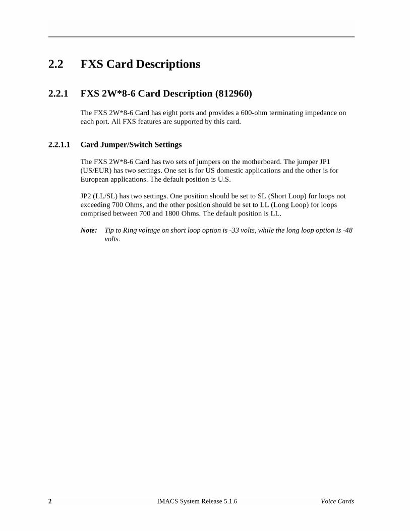
2.2.1.1 Card Jumper/Switch Settings
The FXS 2W*8-6 Card has two sets of jumpers on the motherboard. The jumper JP1 (US/EUR) has two settings. One set is for US domestic applications and the other is for European applications. The default position is U.S.
JP2 (LL/SL) has two settings. One position should be set to SL (Short Loop) for loops not exceeding 700 Ohms, and the other position should be set to LL (Long Loop) for loops comprised between 700 and 1800 Ohms. The default position is LL.
Note: Tip to Ring voltage on short loop option is -33 volts, while the long loop option is -48 volts.
2 IMACS System Release 5.1.6 Voice Cards
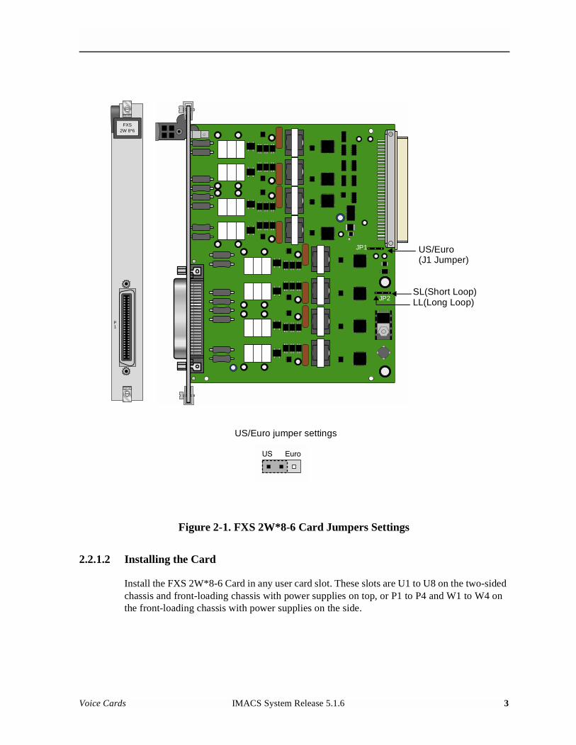
Figure 2-1. FXS 2W*8-6 Card Jumpers Settings
2.2.1.2 Installing the Card
Install the FXS 2W*8-6 Card in any user card slot. These slots are U1 to U8 on the two-sided chassis and front-loading chassis with power supplies on top, or P1 to P4 and W1 to W4 on the front-loading chassis with power supplies on the side.
FXS2W 8*6
P1
JP1
JP2
US/Euro(J1 Jumper)
SL(Short Loop)LL(Long Loop)
US/Euro jumper settings
Voice Cards IMACS System Release 5.1.6 3
Model No.Running Head
2.3 FXS Card User Screens and Settings
2.3.1 FXS Card Main Screen
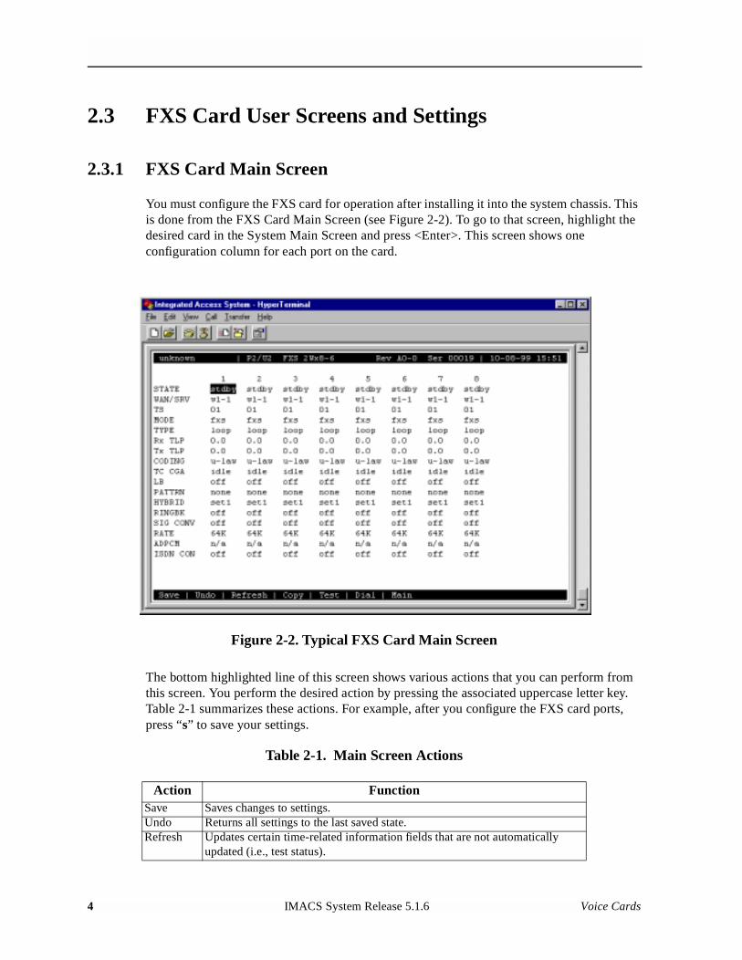
You must configure the FXS card for operation after installing it into the system chassis. This is done from the FXS Card Main Screen (see Figure 2-2). To go to that screen, highlight the desired card in the System Main Screen and press <Enter>. This screen shows one configuration column for each port on the card.
Figure 2-2. Typical FXS Card Main Screen
The bottom highlighted line of this screen shows various actions that you can perform from this screen. You perform the desired action by pressing the associated uppercase letter key. Table 2-1 summarizes these actions. For example, after you configure the FXS card ports, press “s” to save your settings.
Table 2-1. Main Screen Actions
Action FunctionSave Saves changes to settings.Undo Returns all settings to the last saved state.Refresh Updates certain time-related information fields that are not automatically
updated (i.e., test status).
4 IMACS System Release 5.1.6 Voice Cards
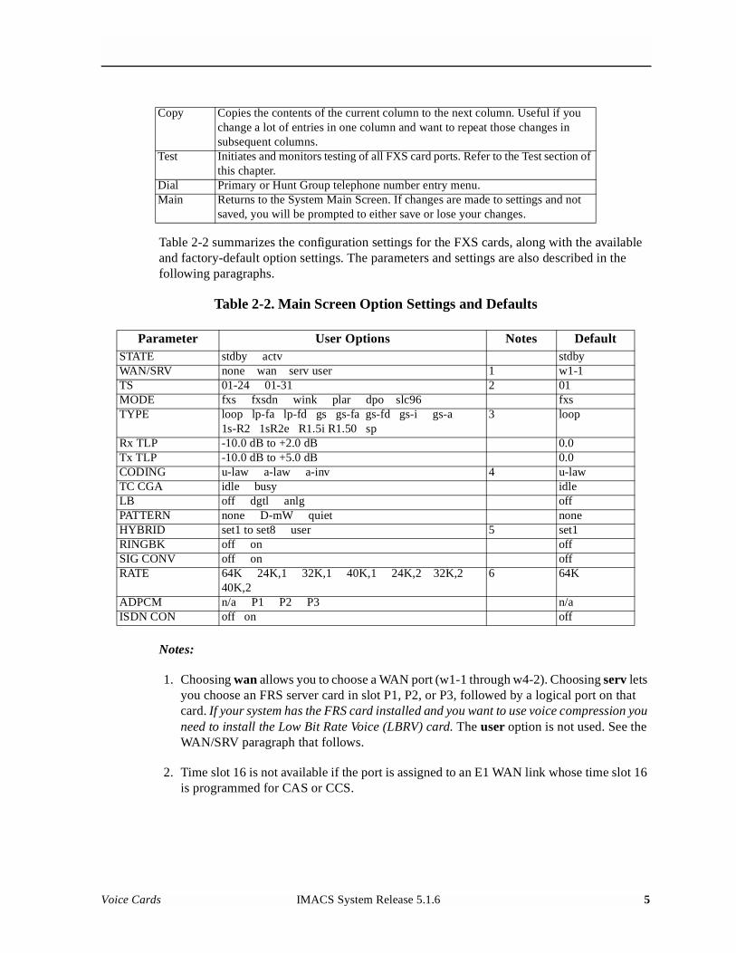
Table 2-2 summarizes the configuration settings for the FXS cards, along with the available and factory-default option settings. The parameters and settings are also described in the following paragraphs.
Table 2-2. Main Screen Option Settings and Defaults
Notes:
1. Choosing wan allows you to choose a WAN port (w1-1 through w4-2). Choosing serv lets you choose an FRS server card in slot P1, P2, or P3, followed by a logical port on that card. If your system has the FRS card installed and you want to use voice compression you need to install the Low Bit Rate Voice (LBRV) card. The user option is not used. See the WAN/SRV paragraph that follows.
2. Time slot 16 is not available if the port is assigned to an E1 WAN link whose time slot 16 is programmed for CAS or CCS.
Copy Copies the contents of the current column to the next column. Useful if you change a lot of entries in one column and want to repeat those changes in subsequent columns.
Test Initiates and monitors testing of all FXS card ports. Refer to the Test section of this chapter.
Dial Primary or Hunt Group telephone number entry menu.Main Returns to the System Main Screen. If changes are made to settings and not
saved, you will be prompted to either save or lose your changes.
Parameter User Options Notes DefaultSTATE stdby actv stdbyWAN/SRV none wan serv user 1 w1-1TS 01-24 01-31 2 01MODE fxs fxsdn wink plar dpo slc96 fxsTYPE loop lp-fa lp-fd gs gs-fa gs-fd gs-i gs-a
1s-R2 1sR2e R1.5i R1.50 sp3 loop
Rx TLP -10.0 dB to +2.0 dB 0.0Tx TLP -10.0 dB to +5.0 dB 0.0CODING u-law a-law a-inv 4 u-lawTC CGA idle busy idleLB off dgtl anlg offPATTERN none D-mW quiet noneHYBRID set1 to set8 user 5 set1RINGBK off on offSIG CONV off on offRATE 64K 24K,1 32K,1 40K,1 24K,2 32K,2
40K,26 64K
ADPCM n/a P1 P2 P3 n/aISDN CON off on off
Voice Cards IMACS System Release 5.1.6 5
Model No.Running Head
3. These options are only valid if the Mode is set to fxs. If the Mode is fxsdn, the Type options are the same as above with the addition of fgd, boa, and lp-sr. If the Mode is plar, the Type options are d3 or d4. If the Mode is dpo, the Type setting will automatically default to dpo. If the Mode is wink, the Type options are loop, lp-fd, gs, gs-i, and gs-a.
4. The default is a-inv for E1 and µ-law for T1. These values will change depending upon the WAN link selected.
5. The default (set1) is the only active option. It balances to the ideal termination of 600 ohms + 2.15 uF. The other settings are reserved for future use.
6. Choosing a Rate other than 64K allows you to select an ADPCM.
STATE
The State setting determines whether the port is active or inactive. An inactive port does not occupy a time slot on a WAN link. Set the State setting to stdby (standby) for ports that are not to be used or that have not yet been configured. Set it to actv (active) for ports that are ready for use.
WAN/SRV
The WAN/SRV setting identifies the WAN link or server card assigned to this port. If you choose wan, you also must select the desired port (w1-1 through w4-2) of a WAN card for transmission over a T1 or E1 link. Or, choose serv to assign the card port to a server card in the system. This is an FRS card, which resides in chassis slot P1, P2, or P3. You must then choose a logical port on that card. The user option is not used.
It is not necessary to assign all ports of the same FXS card to the same WAN link or server card, or to contiguous time slots on a WAN link.
TS
The TS setting identifies the time slot on the WAN link to which this port is assigned. Values range from 1 to 24 for T1 links and 1 to 31 for E1 links. Time slot 16 is not available on E1 links that are programmed for cas or ccs signaling. For a display of the available time slots, refer to the cross-connect map for the WAN link; see Chapter 4, System Configuration and Operation in the System Reference Guide for information about viewing cross-connect maps.
MODE
The Mode setting should be determined by the type of equipment to which the user is connecting the port. All options use two-wire balanced connections. The fxs (Foreign Exchange Station) option allows users to connect the system to a two-way (both inbound and outbound calls) PBX trunk or a key system trunk. The system requires a ringing generator for
6 IMACS System Release 5.1.6 Voice Cards
this option. The fxsdn (Foreign Exchange Station-Defined Network) option provides access to new services offered by advanced networks from many major carriers. The system requires a ringing generator for this option. The wink option uses the same type of signaling as fxsdn and provides a 150-millisecond delay, then a 200-millisecond "wink" back to the central office when the FXS card sees an off-hook condition from the central office. The system requires a ringing generator for this option.
The plar (private line automatic ringdown) option provides point-to-point unswitched connections between two telephone sets. This configuration is usually not attached to an exchange or switch; rather it provides a “hot line” between two locations. The unit requires a ringing generator for this option.
The dpo (Dial Pulse Originating) option allows the unit to attach to out-going one-way trunks from a PBX, key system, or a telephone set. This option is very similar to the fxs option; however, the system does not require a ringing generator.
The slc96 (Subscriber Loop Carrier 96) option connects the card to one-way outgoing trunks from a PBX, CENTREX, key system, or telephone set to an SLC channel. The slc96 mode also must be active on the associated WAN card.
TYPE
The Type setting matches the signaling behavior of the FXS equipment to the remote switch. Use the loop (loop-start) option with POTS stations and simple PBX trunks. Use the lp-fd (loop-start with Forward Disconnect) option when connecting to automated answering equipment. Use the gs (ground-start) option with two-way PBX trunks. This setting helps prevent glaring and call collisions. Use gs-i (ground-start immediate) for equipment requiring a fast response time to the station or PBX. Use gs-a (ground-start automatic) for equipment requiring fast-response time to the central office. Use ls-R2 for CCITT signaling used internationally (immediate R2) which provides immediate seizure acknowledgment to the network. Your selection must match the behavior of both the station equipment and remote central office or PBX.
Use lp-fa or gs-fa when Answer Supervision is required. The selection of Answer Supervision will always use Forward Disconnect. The Forward Disconnect option can also be used without Answer Supervision in both loop and ground start modes (lp-fd and gs-fd).
The lsR2e R2 Signaling for Ericsson switch for incoming and outgoing call modes. The tables below represent FXS ls-R23 signaling modes.
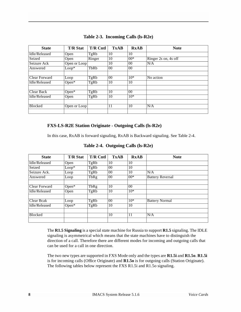
FXS-LS-R2E Office Originate - Incoming Calls (ls-R2e)
In this case, RxAB is Forward signaling. TxAB is Backward signaling. See Table 2-3.
Voice Cards IMACS System Release 5.1.6 7
Model No.Running Head
Table 2-3. Incoming Calls (ls-R2e)
FXS-LS-R2E Station Originate - Outgoing Calls (ls-R2e)
In this case, RxAB is forward signaling, RxAB is Backward signaling. See Table 2-4.
Table 2-4. Outgoing Calls (ls-R2e)
The R1.5 Signaling is a special state machine for Russia to support R1.5 signaling. The IDLE signaling is asymmetrical which means that the state machines have to distinguish the direction of a call. Therefore there are different modes for incoming and outgoing calls that can be used for a call in one direction.
The two new types are supported in FXS Mode only and the types are R1.5i and R1.5o. R1.5i is for incoming calls (Office Originate) and R1.5o is for outgoing calls (Station Originate). The following tables below represent the FXS R1.5i and R1.5o signaling.
State T/R Stat T/R Cntl TxAB RxAB NoteIdle/Released Open TgRb 10 10Seized Open Ringer 10 00* Ringer 2s on, 4s offSeizure Ack Open or Loop 10 00 N/AAnswered Loop* TbRb 00 00
Clear Forward Loop TgRb 00 10* No actionIdle/Released Open* TgRb 10 10
Clear Back Open* TgRb 10 00Idle/Released Open TgRb 10 10*
Blocked Open or Loop 11 10 N/A
State T/R Stat T/R Cntl TxAB RxAB NoteIdle/Released Open TgRb 10 10Seized Loop* TgRb 00 10Seizure Ack. Loop TgRb 00 10 N/AAnswered Loop TbRg 00 00* Battery Reversal
Clear Forward Open* TbRg 10 00Idle/Released Open TgRb 10 10*
Clear Bcak Loop TgRb 00 10* Battery NormalIdle/Released Open* TgRb 10 10
Blocked 10 11 N/A
8 IMACS System Release 5.1.6 Voice Cards
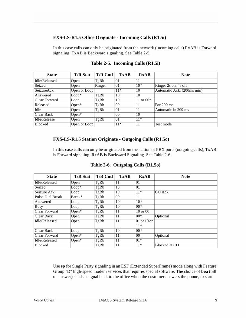
FXS-LS-R1.5 Office Originate - Incoming Calls (R1.5i)
In this case calls can only be originated from the network (incoming calls) RxAB is Forward signaling. TxAB is Backward signaling. See Table 2-5.
Table 2-5. Incoming Calls (R1.5i)
FXS-LS-R1.5 Station Originate - Outgoing Calls (R1.5o)
In this case calls can only be originated from the station or PBX ports (outgoing calls), TxAB is Forward signaling, RxAB is Backward Signaling. See Table 2-6.
Table 2-6. Outgoing Calls (R1.5o)
Use sp for Single Party signaling in an ESF (Extended SuperFrame) mode along with Feature Group "D" high-speed modem services that requires special software. The choice of boa (bill on answer) sends a signal back to the office when the customer answers the phone, to start
State T/R Stat T/R Cntl TxAB RxAB NoteIdle/Released Open TgRb 01 11Seized Open Ringer 01 10* Ringer 2s on, 4s offSeizureAck Open or Loop 11* 10 Automatic Ack. (200ms min)Answered Loop* TgRb 10 10Clear Forward Loop TgRb 10 11 or 00*Released Open* TgRb 00 11 For 200 msIdle Open TgRb 01 11 Automatic in 200 msClear Back Open* 00 10Idle/Release Open TgRb 01 11*Blocked Open or Loop 11* 11 Test mode
State T/R Stat T/R Cntl TxAB RxAB NoteIdle/Released Open TgRb 11 01Seized Loop* TgRb 10 01Seizure Ack. Loop TgRb 10 11* CO Ack.Pulse Dial Break Break* TgRb 00 11Answered Loop TgRb 10 10*Busy Loop TgRb 10 00*Clear Forward Open* TgRb 11 10 or 00Clear Back Open TgRb 11 00* OptionalIdle/Released Open TgRb 11 01 or 10 or
11*Clear Back Loop TgRb 10 00*Clear Forward Open* TgRb 11 00 OptionalIdle/Released Open* TgRb 11 01*Blocked TgRb 11 11* Blocked at CO
Voice Cards IMACS System Release 5.1.6 9
Model No.Running Head
billing for the call. An additional choice of lp-sr (loop-start short ring) is the same as the loop option except that the ringing time is 1 second ON and 2 seconds OFF instead of 2 seconds ON and 4 seconds OFF (using existing option loop/lp-fd).
Selecting the plar option for the Mode of this port causes the system to offer d3 and d4, which are the two common PLAR types. Both of these meet the pre-1988 and post-1988 specifications for PLAR circuits. If you select dpo as the Mode, the Type automatically defaults to dpo.
If slc96 is selected for Mode, the two options supported are sp (single-party POTS) and uvg (universal voice-grade).
CAUTION!
Before activating this port, verify the behavior expected by both the station equipment and remote central office equipment, and be sure the systems are properly configured.
Rx TLP
The Receive Transmission Level Point (TLP) setting controls the amount of gain or loss added to the incoming signal after it is decoded to analog. To increase the signal level, set the Rx TLP setting to a positive value (i.e., the larger the number, the more gain is added). To decrease the signal level, set the Rx TLP setting to a negative value (i.e., the more negative the number, the more the signal level is decreased). For example, an incoming signal at -5 dBm can be increased to -3 dBm by setting Rx TLP to +2 dB. The Rx TLP range is -10.0 dB to +2.0 dB.
Tx TLP
The Transmit TLP setting controls the amount of gain or loss added to a voice signal from the CPE before it is encoded to digital PCM. To increase the signal level, set the Tx TLP setting to a negative value (i.e., the more negative the number, the more gain is added). To decrease the signal level, set the Tx TLP setting to a positive value (i.e., the more positive the number, the more the signal level is decreased). For example, an incoming signal at -5 dBm can be increased to -2 dBm by setting the Tx TLP to -3 dB. The Tx TLP range is -10.0 dB to +5.0 dB.
CODING
The Coding setting sets the PCM companding method used for a port. Generally, the North American T1 environment uses m-law coding, and the International E1 environment uses a-law or a-inv (inverted A-law) coding. The a-inv setting provides a higher ones density than a-law. The default coding setting is determined by the type of associated WAN card.
10 IMACS System Release 5.1.6 Voice Cards
TC CGA
The Trunk Conditioning during Carrier Group Alarm setting defines whether the FXS port should be forced idle or busy upon declaration of a Carrier Group Alarm (CGA) on the WAN link to which the port is assigned. In most cases, you should set this parameter to busy. If a call is in progress when the CGA alarm is received, the system will hold the call for two seconds, drop it, and then busy out the port to the attached PBX for the duration of the alarm. Once the alarm clears, the system will automatically place the port back in the idle mode, making it available to the PBX.
LB
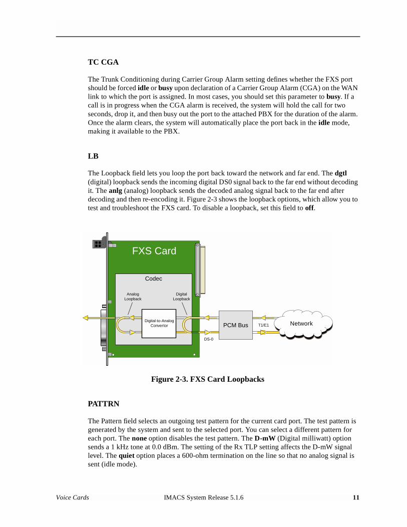
The Loopback field lets you loop the port back toward the network and far end. The dgtl (digital) loopback sends the incoming digital DS0 signal back to the far end without decoding it. The anlg (analog) loopback sends the decoded analog signal back to the far end after decoding and then re-encoding it. Figure 2-3 shows the loopback options, which allow you to test and troubleshoot the FXS card. To disable a loopback, set this field to off.
Figure 2-3. FXS Card Loopbacks
PATTRN
The Pattern field selects an outgoing test pattern for the current card port. The test pattern is generated by the system and sent to the selected port. You can select a different pattern for each port. The none option disables the test pattern. The D-mW (Digital milliwatt) option sends a 1 kHz tone at 0.0 dBm. The setting of the Rx TLP setting affects the D-mW signal level. The quiet option places a 600-ohm termination on the line so that no analog signal is sent (idle mode).
Network
FXS Card
Codec
PCM BusDigital-to-Analog
Convertor
AnalogLoopback
DigitalLoopback
T1/E1
DS-0
Voice Cards IMACS System Release 5.1.6 11
Model No.Running Head
HYBRID
The Hybrid option assigns a three byte pattern to define the adjustment for return loss (similar to Build Out Capacitors). The default, set1, balances to the ideal termination of 600 ohms + 2.15 uF. The other settings are reserved for future use.
RINGBK
The ringback setting specifies whether a ringback tone is generated by the system and sent towards the network. Turn this option off when the network service does not provide an audible ringing tone to the calling party.
SIG CONV
The Signaling Conversion parameter allows you to change the transmit ABCD signaling bits from CCITT (E1) to ANSI (T1) standards. This conversion is completed regardless of the type of WAN card (CSU/DSX or CEPT) to which the FXS card is attached.
The options are off if ANSI signaling is used and on to convert transmit signaling from ANSI to CCITT format according to the Interface Card Conversion Table for FXS signaling. This setting also converts receive signaling from CCITT to ANSI.
RATE
The Rate parameter allows you to use the voice compression capabilities of an ADPCM card. If that card is not present in the system, the Rate stays at 64k and cannot be changed. The 64k option is the normal encoding/decoding rate for voice circuits.
ADPCM voice channels are assigned in pairs by designating two voice ports (E&M, FXO, or FXS) to the same WAN link and time slot, and selecting rate settings for the pair that add up to 64 kbps. The following combinations are possible:
• 24K,1+40K,2 (24 kb coding on one side of the time slot and 40 kb coding on the other side of the same time slot)
• 32K,1+32K,2 (32 kb encoding on each side of a time slot)
• 40K,1+24K,2 (40 kb coding on one side of the time slot and 24 kb coding on the other side)
Number 1 after the rate setting assigns that portion of the voice port pair to the odd side of the ADPCM pair. Number 2 after the rate setting assigns that portion of the voice port pair to the even side of the ADPCM pair.
The number 1 after the rate setting assigns that portion of the voice port pair to the odd side of the ADPCM pair. The number 2 after the rate setting assigns that portion of the voice port pair to the even side of the ADPCM pair.
12 IMACS System Release 5.1.6 Voice Cards
For more information about voice port assignments to the ADPCM card, please consult the ADPCM section of the Server Card Reference Guide.
ADPCM
The ADPCM parameter lets the user choose which ADPCM card to place this E&M port. The default setting is n/a and only changes when a Rate smaller than 64k is selected (see above). The user is then allowed to select which ADPCM card to use for the port (this assignment is made by chassis slot number). The options are slots P1, P2, and P3.
ISDN CON
The ISDN Connect parameter displays whether the ISDN connection is on or off. The default setting is always off.
2.3.2 Test Screen
The Test option facilitates testing and maintenance by allowing you to monitor and set the status of the analog interface leads, and to monitor or set the value of the A, B, C, and D signaling bits of all FXS circuits on that card. In cross-connect systems, the test option also allows you to apply test patterns and tones towards the user and network sides of the system.
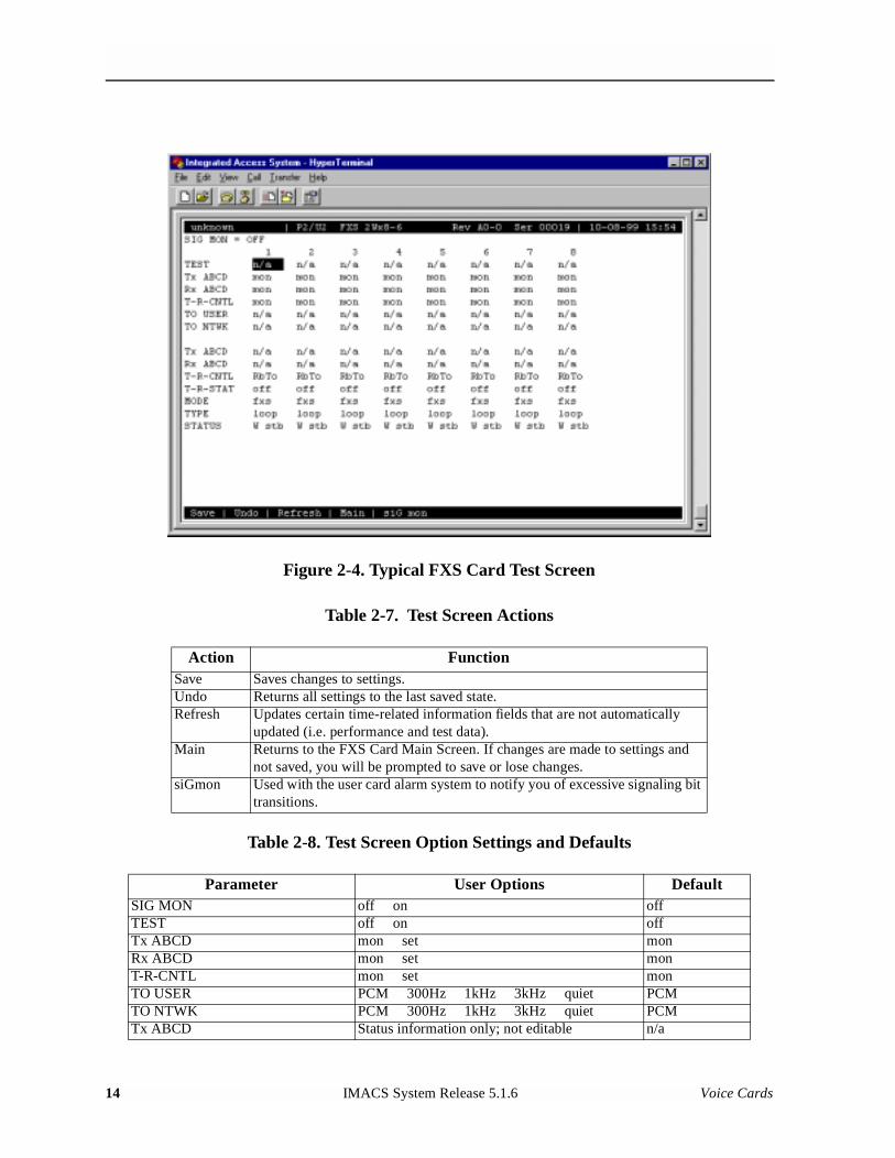
Figure 2-4 shows the FXS Card Test Screen parameters, Table 2-7 lists some actions you can perform from this screen, and Table 2-8 shows the settings for each parameter.
Voice Cards IMACS System Release 5.1.6 13
Model No.Running Head
Figure 2-4. Typical FXS Card Test Screen
Table 2-7. Test Screen Actions
Table 2-8. Test Screen Option Settings and Defaults
Action FunctionSave Saves changes to settings.Undo Returns all settings to the last saved state.Refresh Updates certain time-related information fields that are not automatically
updated (i.e. performance and test data).Main Returns to the FXS Card Main Screen. If changes are made to settings and
not saved, you will be prompted to save or lose changes.siGmon Used with the user card alarm system to notify you of excessive signaling bit
transitions.
Parameter User Options DefaultSIG MON off on offTEST off on offTx ABCD mon set monRx ABCD mon set monT-R-CNTL mon set monTO USER PCM 300Hz 1kHz 3kHz quiet PCMTO NTWK PCM 300Hz 1kHz 3kHz quiet PCMTx ABCD Status information only; not editable n/a
14 IMACS System Release 5.1.6 Voice Cards
SIG MON
The Signaling Monitor feature works with the user card alarm system to detect excessive signaling bit transitions. The system will generate alarms if the number of transitions of any signaling bit in transmit or receive direction for an active port exceeds 255 in any four second interval. The options are off and on, and they are toggled by pressing “g” (siGmon command) in the Test Screen.
TEST
The Test parameter shows if the port is in test mode or not. Inactive ports and ports that are assigned to inactive WANs will show a test status of n/a. The test status options for active ports are off and on.
Tx ABCD
The Transmit ABCD setting allows the user to either monitor the status of the ABCD signaling bits being transmitted towards the network or set a specific ABCD pattern for testing the transmit side of the circuit. The options for this field are mon (monitor) or set. Choosing set will bring up a four digit field for users to input the ABCD pattern they want to transmit. Any four-digit combination of ones and zeros is acceptable for this setting.
Rx ABCD
The Receive ABCD setting allows the user to either monitor the status of the ABCD signaling bits being received from the network or set a specific ABCD pattern for testing the receive side of the circuit. The options for this field are mon (monitor) or set. Choosing set will bring up a four digit field for users to input the ABCD pattern they want to receive. Any four digit combination of ones and zeros is acceptable.
T-R-CNTL
The Tip and Ring Control setting allows you to either mon (monitor) or set (set) the state of the Tip and Ring leads of an FXS port. Choosing set will display the following options (b = battery, o = open, g = ground):
• RbTo (-48V is applied to the Ring lead and the Tip lead is open)
Rx ABCD Status information only; not editable n/aT-R-CNTL Status information only; not editable n/aT-R-STAT Status information only; not editable n/aMODE Status information only; not editable n/aTYPE Status information only; not editable n/aSTATUS Status information only; not editable n/a
Voice Cards IMACS System Release 5.1.6 15
Model No.Running Head
• TbRo (-48V is applied to the Tip lead and the Ring lead is open)
• RbTg (-48V is applied to the Ring lead and the Tip lead is grounded)
• TbRg (-48V is applied to the Tip lead and the Ring lead is grounded)
TO USER
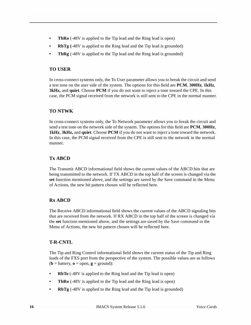
In cross-connect systems only, the To User parameter allows you to break the circuit and send a test tone on the user side of the system. The options for this field are PCM, 300Hz, 1kHz, 3kHz, and quiet. Choose PCM if you do not want to inject a tone toward the CPE. In this case, the PCM signal received from the network is still sent to the CPE in the normal manner.
TO NTWK
In cross-connect systems only, the To Network parameter allows you to break the circuit and send a test tone on the network side of the system. The options for this field are PCM, 300Hz, 1kHz, 3kHz, and quiet. Choose PCM if you do not want to inject a tone toward the network. In this case, the PCM signal received from the CPE is still sent to the network in the normal manner.
Tx ABCD
The Transmit ABCD informational field shows the current values of the ABCD bits that are being transmitted to the network. If TX ABCD in the top half of the screen is changed via the set function mentioned above, and the settings are saved by the Save command in the Menu of Actions, the new bit pattern chosen will be reflected here.
Rx ABCD
The Receive ABCD informational field shows the current values of the ABCD signaling bits that are received from the network. If RX ABCD in the top half of the screen is changed via the set function mentioned above, and the settings are saved by the Save command in the Menu of Actions, the new bit pattern chosen will be reflected here.
T-R-CNTL
The Tip and Ring Control informational field shows the current status of the Tip and Ring leads of the FXS port from the perspective of the system. The possible values are as follows(b = battery, o = open, g = ground):
• RbTo (-48V is applied to the Ring lead and the Tip lead is open)
• TbRo (-48V is applied to the Tip lead and the Ring lead is open)
• RbTg (-48V is applied to the Ring lead and the Tip lead is grounded)
16 IMACS System Release 5.1.6 Voice Cards
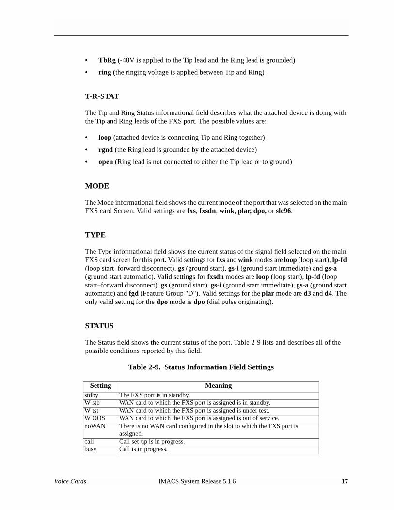
• TbRg (-48V is applied to the Tip lead and the Ring lead is grounded)
• ring (the ringing voltage is applied between Tip and Ring)
T-R-STAT
The Tip and Ring Status informational field describes what the attached device is doing with the Tip and Ring leads of the FXS port. The possible values are:
• loop (attached device is connecting Tip and Ring together)
• rgnd (the Ring lead is grounded by the attached device)
• open (Ring lead is not connected to either the Tip lead or to ground)
MODE
The Mode informational field shows the current mode of the port that was selected on the main FXS card Screen. Valid settings are fxs, fxsdn, wink, plar, dpo, or slc96.
TYPE
The Type informational field shows the current status of the signal field selected on the main FXS card screen for this port. Valid settings for fxs and wink modes are loop (loop start), lp-fd (loop start–forward disconnect), gs (ground start), gs-i (ground start immediate) and gs-a (ground start automatic). Valid settings for fxsdn modes are loop (loop start), lp-fd (loop start–forward disconnect), gs (ground start), gs-i (ground start immediate), gs-a (ground start automatic) and fgd (Feature Group "D"). Valid settings for the plar mode are d3 and d4. The only valid setting for the dpo mode is dpo (dial pulse originating).
STATUS
The Status field shows the current status of the port. Table 2-9 lists and describes all of the possible conditions reported by this field.
Table 2-9. Status Information Field Settings
Setting Meaningstdby The FXS port is in standby.W stb WAN card to which the FXS port is assigned is in standby.W tst WAN card to which the FXS port is assigned is under test.W OOS WAN card to which the FXS port is assigned is out of service.noWAN There is no WAN card configured in the slot to which the FXS port is
assigned.call Call set-up is in progress.busy Call is in progress.
Voice Cards IMACS System Release 5.1.6 17
Model No.Running Head
2.4 FXS Error Messages
Refer to Appendix B in the System Reference Guide for further information on Error Messages regarding this card.
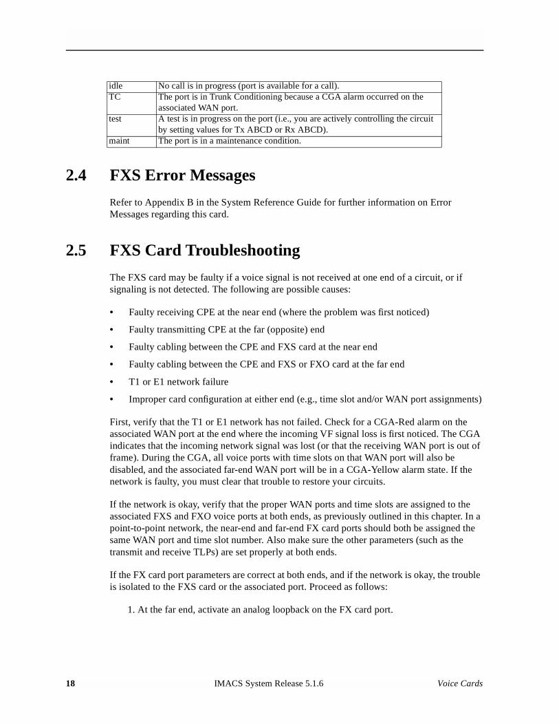
2.5 FXS Card Troubleshooting
The FXS card may be faulty if a voice signal is not received at one end of a circuit, or if signaling is not detected. The following are possible causes:
• Faulty receiving CPE at the near end (where the problem was first noticed)
• Faulty transmitting CPE at the far (opposite) end
• Faulty cabling between the CPE and FXS card at the near end
• Faulty cabling between the CPE and FXS or FXO card at the far end
• T1 or E1 network failure
• Improper card configuration at either end (e.g., time slot and/or WAN port assignments)
First, verify that the T1 or E1 network has not failed. Check for a CGA-Red alarm on the associated WAN port at the end where the incoming VF signal loss is first noticed. The CGA indicates that the incoming network signal was lost (or that the receiving WAN port is out of frame). During the CGA, all voice ports with time slots on that WAN port will also be disabled, and the associated far-end WAN port will be in a CGA-Yellow alarm state. If the network is faulty, you must clear that trouble to restore your circuits.
If the network is okay, verify that the proper WAN ports and time slots are assigned to the associated FXS and FXO voice ports at both ends, as previously outlined in this chapter. In a point-to-point network, the near-end and far-end FX card ports should both be assigned the same WAN port and time slot number. Also make sure the other parameters (such as the transmit and receive TLPs) are set properly at both ends.
If the FX card port parameters are correct at both ends, and if the network is okay, the trouble is isolated to the FXS card or the associated port. Proceed as follows:
1. At the far end, activate an analog loopback on the FX card port.
idle No call is in progress (port is available for a call).TC The port is in Trunk Conditioning because a CGA alarm occurred on the
associated WAN port.test A test is in progress on the port (i.e., you are actively controlling the circuit
by setting values for Tx ABCD or Rx ABCD).maint The port is in a maintenance condition.
18 IMACS System Release 5.1.6 Voice Cards
2. Send a 0 dBm (digital milliwatt) test signal toward the CPE at that end. That signal will be substituted for the normal signal coming from the far-end CPE; it will be sent back to the CPE at your end via the loopback path.
3. Check your CPE for this signal. If it is present, the far-end CPE or cabling to the far-end FX card is probably faulty. Disable the loopback and test signal there, and fix the problem. If you still don’t receive a signal, go to step 4.
4. At your end, go to the FXS Card Main Screen and send a digital milliwatt test tone (0 dBm) toward the CPE. If you still don’t receive a signal, check the cabling from the FXS card to your CPE, and check the CPE itself. If those items are okay, replace the FXS card at your end.
5. If the FXS card is determined to be faulty, replace it and return the faulty unit for repair to the location specified by your distributor.
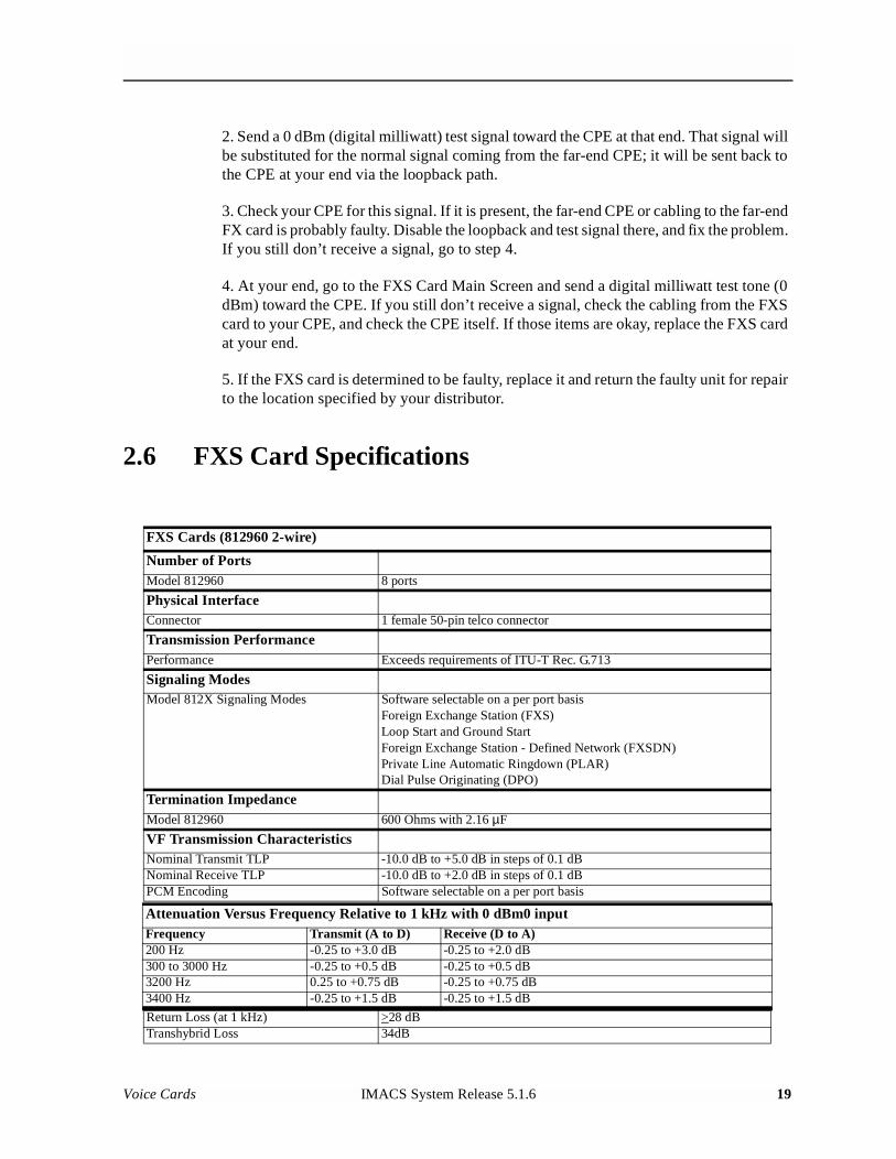
2.6 FXS Card Specifications
FXS Cards (812960 2-wire)
Number of PortsModel 812960 8 ports
Physical InterfaceConnector 1 female 50-pin telco connector
Transmission PerformancePerformance Exceeds requirements of ITU-T Rec. G.713
Signaling ModesModel 812X Signaling Modes Software selectable on a per port basis
Foreign Exchange Station (FXS)Loop Start and Ground StartForeign Exchange Station - Defined Network (FXSDN)Private Line Automatic Ringdown (PLAR)Dial Pulse Originating (DPO)
Termination ImpedanceModel 812960 600 Ohms with 2.16 µF
VF Transmission CharacteristicsNominal Transmit TLP -10.0 dB to +5.0 dB in steps of 0.1 dBNominal Receive TLP -10.0 dB to +2.0 dB in steps of 0.1 dBPCM Encoding Software selectable on a per port basis
Attenuation Versus Frequency Relative to 1 kHz with 0 dBm0 inputFrequency Transmit (A to D) Receive (D to A)200 Hz -0.25 to +3.0 dB -0.25 to +2.0 dB300 to 3000 Hz -0.25 to +0.5 dB -0.25 to +0.5 dB3200 Hz 0.25 to +0.75 dB -0.25 to +0.75 dB3400 Hz -0.25 to +1.5 dB -0.25 to +1.5 dB
Return Loss (at 1 kHz) >28 dBTranshybrid Loss 34dB
Voice Cards IMACS System Release 5.1.6 19
Model No.Running Head
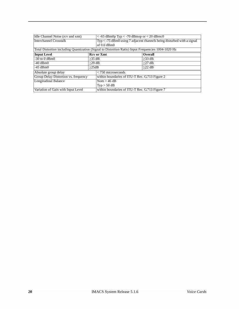
Idle Channel Noise (rcv and xmt) < -65 dBm0p Typ < -70 dBmop or < 20 dBrnc0Interchannel Crosstalk Typ < -75 dBm0 using 7 adjacent channels being disturbed with a signal
of 0.0 dBm0Total Distortion including Quantization (Signal to Distortion Ratio) Input Frequencies 1004-1020 Hz
Input Level Rcv or Xmt Overall-30 to 0 dBm0 >35 dB >33 dB-40 dBm0 >29 dB >27 dB-45 dBm0 >25dB >22 dB
Absolute group delay < 750 microsecondsGroup Delay Distortion vs. frequency within boundaries of ITU-T Rec. G.713 Figure 2Longitudinal Balance Nom > 46 dB
Typ > 50 dBVariation of Gain with Input Level within boundaries of ITU-T Rec. G.713 Figure 7
20 IMACS System Release 5.1.6 Voice Cards
Chapter 3FXO Card
3.1 Introduction
This chapter provides installation, configuration, and troubleshooting information for the Foreign Exchange - Office (FXO) Card, which is identified as a FXO 2W*8-6 card on its faceplate ejector.
The FXO 2W*8-6 Card manages the flow of FXO voice traffic through the Integrated Access System. Each card encodes analog (voice, VF) signals to a digital bloodstream at the local system for transmission over a T1 or E1 network. It also decodes the digital signals to analog at the remote system.
The card has a two-wire interface and supports Foreign Exchange - Office (FXO), Manual Ringdown (MRD), Foreign Exchange Office-Defined Network (FXODN), and Dial-Pulse Terminating (DPT) operations.
The FXO card also can use the voice compression features of an ADPCM card.
Host code 5.1.6 adds the Answer Supervision function to both the loop start and ground signal options. The new states (which are now combined with forward disconnect) are:
• FXO loop start forward disconnect and answer supervision (lp-fa)
• FXO ground start forward disconnect and answer supervision (gs-fa)
• FXO ground start forward disconnect (gs-fd)
Answer Supervision (AS) is a supplemental feature available for analog voice-grade switched-access lines that use loop-start signaling or ground-start signaling. When the Answer Supervision feature is available, an originating call from a Customer Installation (CI) (or Customer's Premises) receives an electrical signal indicating that the terminating (called) CI has answered. The AS signal is a polarity reversal of the voltage that the network applies between the tip conductor and the ring conductor at the Network Interface. The most common application of AS is to determine if and when the called party has answered the phone for billing purposes.
Host code 5.1.6 also adds the ability to detect 25 HZ ringing frequency in both options. The specification for incoming ringing signal detection at the switch end is 17 to 28 Hz, at 40 to 110 Vrms. Ringing output at the FXS end is governed by the ring generator.
Voice Cards IMACS System Release 5.1.6 1
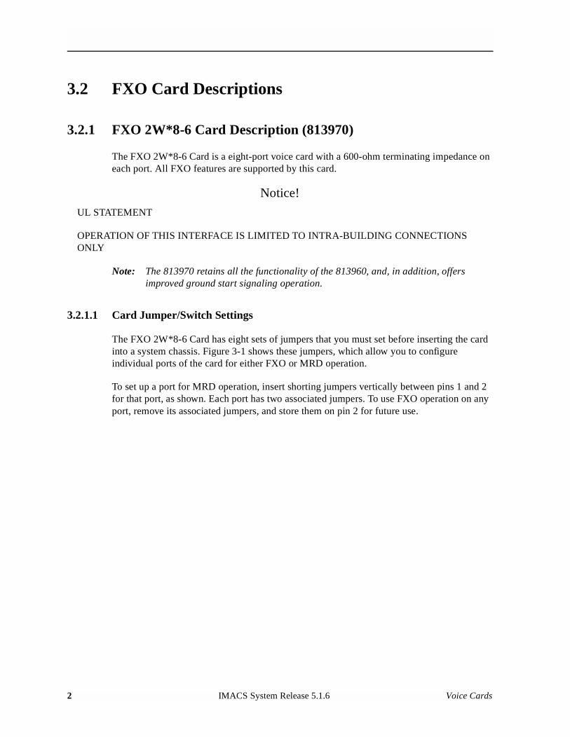
Model No.Running Head
3.2 FXO Card Descriptions
3.2.1 FXO 2W*8-6 Card Description (813970)
The FXO 2W*8-6 Card is a eight-port voice card with a 600-ohm terminating impedance on each port. All FXO features are supported by this card.
Notice!
UL STATEMENT
OPERATION OF THIS INTERFACE IS LIMITED TO INTRA-BUILDING CONNECTIONS ONLY
Note: The 813970 retains all the functionality of the 813960, and, in addition, offers improved ground start signaling operation.
3.2.1.1 Card Jumper/Switch Settings
The FXO 2W*8-6 Card has eight sets of jumpers that you must set before inserting the card into a system chassis. Figure 3-1 shows these jumpers, which allow you to configure individual ports of the card for either FXO or MRD operation.
To set up a port for MRD operation, insert shorting jumpers vertically between pins 1 and 2 for that port, as shown. Each port has two associated jumpers. To use FXO operation on any port, remove its associated jumpers, and store them on pin 2 for future use.
2 IMACS System Release 5.1.6 Voice Cards
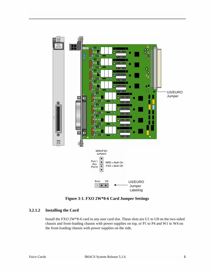
Figure 3-1. FXO 2W*8-6 Card Jumper Settings
3.2.1.2 Installing the Card
Install the FXO 2W*8-6 card in any user card slot. These slots are U1 to U8 on the two-sided chassis and front-loading chassis with power supplies on top, or P1 to P4 and W1 to W4 on the front-loading chassis with power supplies on the side.
FXO2W*8-6
P1
Port #8
Port #7
Port #6
Port #5
Port #4
Port #3
Port #2
Port #1
US/EUROJumper
JumperUS/EURO
Labeling
Voice Cards IMACS System Release 5.1.6 3
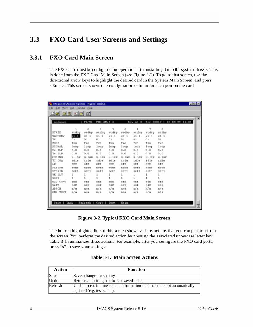
Model No.Running Head
3.3 FXO Card User Screens and Settings
3.3.1 FXO Card Main Screen
The FXO Card must be configured for operation after installing it into the system chassis. This is done from the FXO Card Main Screen (see Figure 3-2). To go to that screen, use the directional arrow keys to highlight the desired card in the System Main Screen, and press <Enter>. This screen shows one configuration column for each port on the card.
Figure 3-2. Typical FXO Card Main Screen
The bottom highlighted line of this screen shows various actions that you can perform from the screen. You perform the desired action by pressing the associated uppercase letter key. Table 3-1 summarizes these actions. For example, after you configure the FXO card ports, press “s” to save your settings.
Table 3-1. Main Screen Actions
Action FunctionSave Saves changes to settings.Undo Returns all settings to the last saved state.Refresh Updates certain time-related information fields that are not automatically
updated (e.g. test status).
4 IMACS System Release 5.1.6 Voice Cards
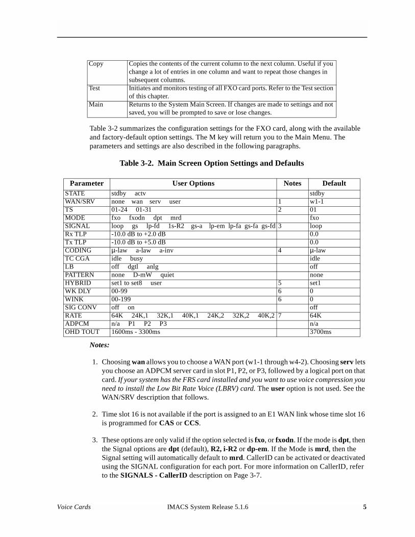
Table 3-2 summarizes the configuration settings for the FXO card, along with the available and factory-default option settings. The M key will return you to the Main Menu. The parameters and settings are also described in the following paragraphs.
Table 3-2. Main Screen Option Settings and Defaults
Notes:
1. Choosing wan allows you to choose a WAN port (w1-1 through w4-2). Choosing serv lets you choose an ADPCM server card in slot P1, P2, or P3, followed by a logical port on that card. If your system has the FRS card installed and you want to use voice compression you need to install the Low Bit Rate Voice (LBRV) card. The user option is not used. See the WAN/SRV description that follows.
2. Time slot 16 is not available if the port is assigned to an E1 WAN link whose time slot 16 is programmed for CAS or CCS.
3. These options are only valid if the option selected is fxo, or fxodn. If the mode is dpt, then the Signal options are dpt (default), R2, i-R2 or dp-em. If the Mode is mrd, then the Signal setting will automatically default to mrd. CallerID can be activated or deactivated using the SIGNAL configuration for each port. For more information on CallerID, refer to the SIGNALS - CallerID description on Page 3-7.
Copy Copies the contents of the current column to the next column. Useful if you change a lot of entries in one column and want to repeat those changes in subsequent columns.
Test Initiates and monitors testing of all FXO card ports. Refer to the Test section of this chapter.
Main Returns to the System Main Screen. If changes are made to settings and not saved, you will be prompted to save or lose changes.
Parameter User Options Notes DefaultSTATE stdby actv stdbyWAN/SRV none wan serv user 1 w1-1TS 01-24 01-31 2 01MODE fxo fxodn dpt mrd fxoSIGNAL loop gs lp-fd 1s-R2 gs-a lp-em lp-fa gs-fa gs-fd 3 loopRx TLP -10.0 dB to +2.0 dB 0.0Tx TLP -10.0 dB to +5.0 dB 0.0CODING µ-law a-law a-inv 4 µ-lawTC CGA idle busy idleLB off dgtl anlg offPATTERN none D-mW quiet noneHYBRID set1 to set8 user 5 set1WK DLY 00-99 6 0WINK 00-199 6 0SIG CONV off on offRATE 64K 24K,1 32K,1 40K,1 24K,2 32K,2 40K,2 7 64KADPCM n/a P1 P2 P3 n/aOHD TOUT 1600ms - 3300ms 3700ms
Voice Cards IMACS System Release 5.1.6 5
Model No.Running Head
4. The default is a-inv for E1 and µ-law for T1. These values will change depending upon the WAN link selected.
5. The default, set1, is the only active option. It balances to the ideal termination of 600 ohms + 2.15 µF. The other settings are reserved for future use.
6. These settings should be used with fxodn and dpt modes only.
7. Choosing a Rate other than 64K allows you to select an ADPCM slot.
STATE
The State setting determines whether the port is active or inactive. An inactive port does not occupy a time slot on a WAN link. Set the State setting to standby (stdby) for ports you are not using, or have not yet configured. Set it to active (actv) for ports that are ready for use.
WAN/SRV
The WAN/SRV setting identifies the WAN link or server card assigned to this port. If you choose wan, you also must select the desired port (w1-1 through w4-2) of a WAN card for transmission over a T1 or E1 link. Or, choose serv to assign the card port to a server card in the system. This can be an ADPCM or FRS card, which resides in chassis slot P1, P2, or P3. You must then choose a logical port on that card. The user option is not used.
It is not necessary to assign all ports of the same FXO card to the same WAN link or server card, or to contiguous time slots on a WAN link.
TS
The TS setting identifies the time slot on the WAN link to which this port is assigned. Values range from 1-24 for T1 links and 1-31 for E1 links. Time slot 16 is not available on E1 links that are programmed for cas or ccs signaling. For a display of the available time slots, refer to your cross-connect map for the WAN link.
MODE
The Mode setting should be determined by the type of equipment to which you connect the port. All options use two-wire balanced connections. The fxo (Foreign Exchange Office) option allows you to connect the system to a 2 way PBX trunk (both inbound and outbound calls) or a key system trunk. The fxodn (Foreign Exchange Office-Defined Network) option provides access to new services offered by advanced networks from many major carriers. The dpt (Dial Pulse Terminating) option allows the unit to attach to incoming one-way trunks from a PBX, key system, or a telephone set.
6 IMACS System Release 5.1.6 Voice Cards
The mrd (manual ringdown) option provides point-to-point unswitched connections between two telephone sets. This configuration is usually not attached to an exchange or switch; rather it provides a “hot line” between two locations. The system requires hardware changes and a ringing generator for this option (see instructions later in this chapter).
SIGNALS
The Signal setting matches the signaling behavior of the FXS equipment and the local switch. Use the loop (Loop Start) option with CO lines and simple PBX trunks. Use the gs (Ground Start) option with two-way PBX trunks because it helps to prevent glaring or call collisions. Use the lp-fd (Loop Start–Forward Disconnect) option with automated answering equipment at the far end. The ls-R2 (Loop Start–R2 protocol) option is provided for a CCITT R2 interface.
Use gs-a (ground-start automatic) option for equipment requiring fast-response time to the central office. The lp-em (Loop Start–R2 electromechanical) option for use on Russian telephone systems.
The CallerID writeup on page 3-7 and the OHD TOUT writeup on page 3-11 describes how you set the on-hook data time out between power rings. If the line goes off-hook before or during the data transmission, data transmission shall be pre-empted or stopped and normal call completion treatment shall be provided.
If you selected the dpt option for the Mode of any port, then the three options that are supported under Signal are dpt for standard Dial Pulse Termination signaling used in North America, R2 for CCITT signaling used internationally, i-R2 (immediate R2) which provides immediate seizure acknowledgment to the network and dp-em (Dial Pulse Electromechanical) used for timing relays that are specific to Russia. If you select mrd as the Mode, then Signal will automatically default to mrd. If you select fxodn in Mode the options are loop, gs, lp-fd, R2, gs-a and lp-em. For fxo the option is listed ls-R2 instead of R2, but the options are the same.
Use lp-fa or gs-fa when Answer Supervision is required. The selection of Answer Supervision will always use Forward Disconnect. The Forward Disconnect option can also be used without Answer Supervision in both loop and ground start modes (lp-fd and gs-fd).
CAUTION!Before activating a port, verify the behavior expected by both the station equipment and the remote central office equipment and ensure that you have the system properly configured.
Voice Cards IMACS System Release 5.1.6 7
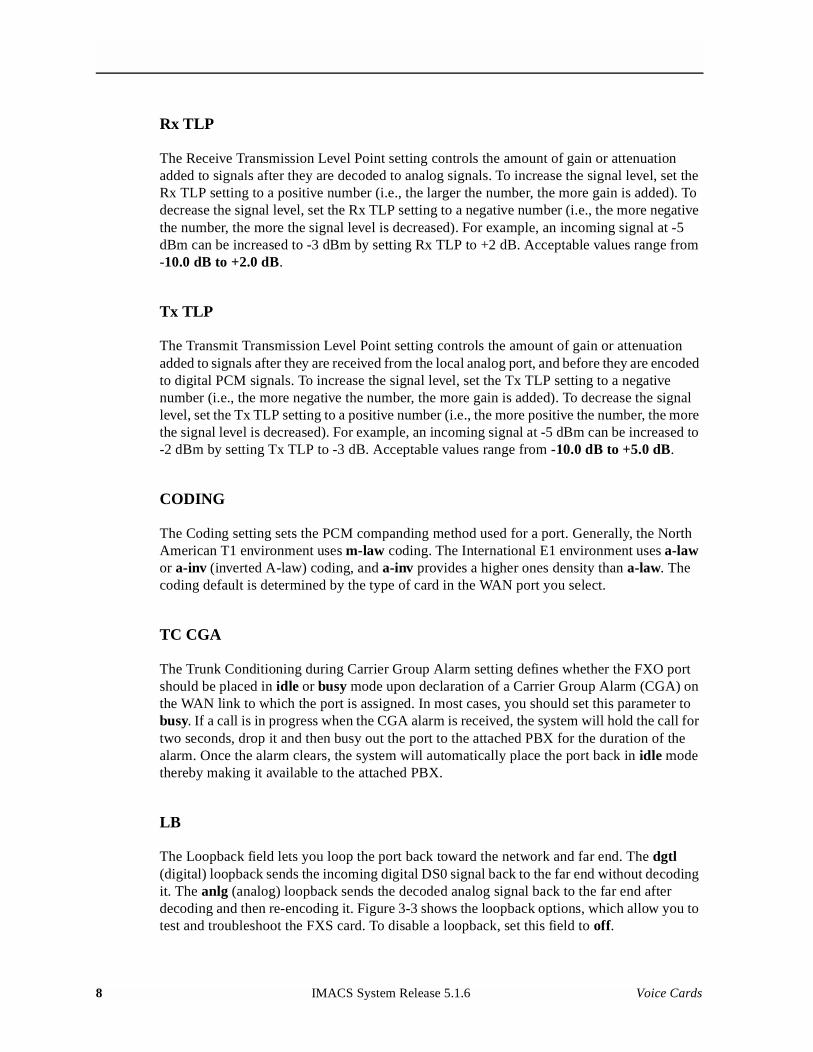
Model No.Running Head
Rx TLP
The Receive Transmission Level Point setting controls the amount of gain or attenuation added to signals after they are decoded to analog signals. To increase the signal level, set the Rx TLP setting to a positive number (i.e., the larger the number, the more gain is added). To decrease the signal level, set the Rx TLP setting to a negative number (i.e., the more negative the number, the more the signal level is decreased). For example, an incoming signal at -5 dBm can be increased to -3 dBm by setting Rx TLP to +2 dB. Acceptable values range from -10.0 dB to +2.0 dB.
Tx TLP
The Transmit Transmission Level Point setting controls the amount of gain or attenuation added to signals after they are received from the local analog port, and before they are encoded to digital PCM signals. To increase the signal level, set the Tx TLP setting to a negative number (i.e., the more negative the number, the more gain is added). To decrease the signal level, set the Tx TLP setting to a positive number (i.e., the more positive the number, the more the signal level is decreased). For example, an incoming signal at -5 dBm can be increased to -2 dBm by setting Tx TLP to -3 dB. Acceptable values range from -10.0 dB to +5.0 dB.
CODING
The Coding setting sets the PCM companding method used for a port. Generally, the North American T1 environment uses m-law coding. The International E1 environment uses a-law or a-inv (inverted A-law) coding, and a-inv provides a higher ones density than a-law. The coding default is determined by the type of card in the WAN port you select.
TC CGA
The Trunk Conditioning during Carrier Group Alarm setting defines whether the FXO port should be placed in idle or busy mode upon declaration of a Carrier Group Alarm (CGA) on the WAN link to which the port is assigned. In most cases, you should set this parameter to busy. If a call is in progress when the CGA alarm is received, the system will hold the call for two seconds, drop it and then busy out the port to the attached PBX for the duration of the alarm. Once the alarm clears, the system will automatically place the port back in idle mode thereby making it available to the attached PBX.
LB
The Loopback field lets you loop the port back toward the network and far end. The dgtl (digital) loopback sends the incoming digital DS0 signal back to the far end without decoding it. The anlg (analog) loopback sends the decoded analog signal back to the far end after decoding and then re-encoding it. Figure 3-3 shows the loopback options, which allow you to test and troubleshoot the FXS card. To disable a loopback, set this field to off.
8 IMACS System Release 5.1.6 Voice Cards
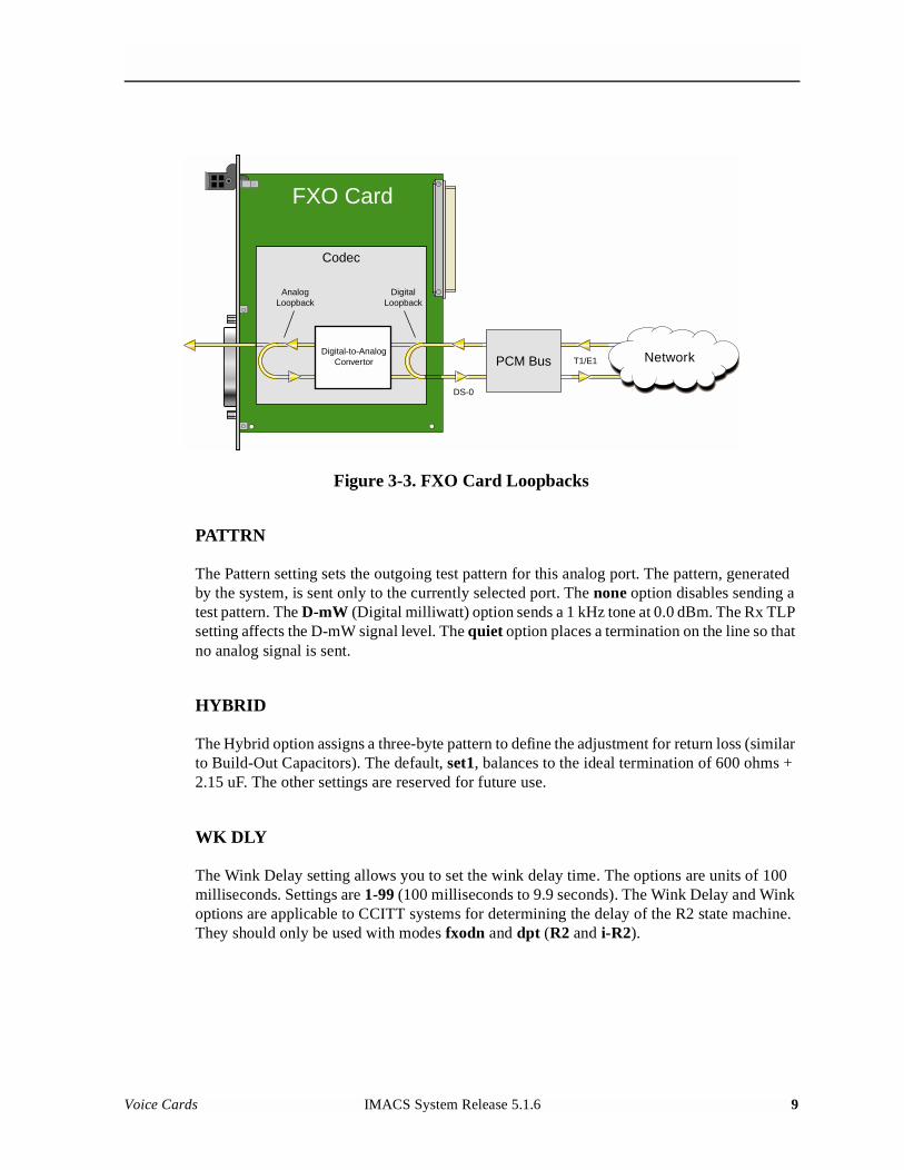
Figure 3-3. FXO Card Loopbacks
PATTRN
The Pattern setting sets the outgoing test pattern for this analog port. The pattern, generated by the system, is sent only to the currently selected port. The none option disables sending a test pattern. The D-mW (Digital milliwatt) option sends a 1 kHz tone at 0.0 dBm. The Rx TLP setting affects the D-mW signal level. The quiet option places a termination on the line so that no analog signal is sent.
HYBRID
The Hybrid option assigns a three-byte pattern to define the adjustment for return loss (similar to Build-Out Capacitors). The default, set1, balances to the ideal termination of 600 ohms + 2.15 uF. The other settings are reserved for future use.
WK DLY
The Wink Delay setting allows you to set the wink delay time. The options are units of 100 milliseconds. Settings are 1-99 (100 milliseconds to 9.9 seconds). The Wink Delay and Wink options are applicable to CCITT systems for determining the delay of the R2 state machine. They should only be used with modes fxodn and dpt (R2 and i-R2).
Network
FXO Card
Codec
PCM BusDigital-to-Analog
Convertor
AnalogLoopback
DigitalLoopback
T1/E1
DS-0
Voice Cards IMACS System Release 5.1.6 9
Model No.Running Head
WINK
The Wink setting allows you to set the wink duration time. The options are units of 100 milliseconds. Settings are 1-99 (100 milliseconds to 9.9 seconds). This option is only applicable with modes fxodn and dpt (R2 and i-R2).
SIG CONV
The Signaling Conversion parameter allows you to change the ABCD signaling bits from CCITT (E1) to ANSI (T1) standards. This conversion is completed regardless of the type of WAN aggregate (CSU/DSX or CEPT) to which it is attached. The options are off (which means that ANSI signaling is used) and on (which converts transmit signaling from ANSI to CCITT format according to the Interface Card Conversion Table for FXO signaling, and also converts receive signaling from CCITT to ANSI).
RATE
The Rate parameter allows you to use the voice compression capabilities of the ADPCM resource card. If that card is not present in the system, changes cannot be made to this setting. The 64K option (default) does not use ADPCM resources (it is the normal operation rate for voice circuits).
ADPCM voice channels are assigned in pairs by designating two voice ports (E&M, FXO or FXS) to the same WAN link and time slot and selecting rate settings for the pair that add up to 64kbps (i.e. [24K,1+40K,2],[32K,1+32K,2] and [40K,1+24K,2]). The numeral 1 after the rate setting assigns that portion of the voice port pair to the odd side of the ADPCM pair. The numeral 2 after the rate setting assigns that portion of the voice port pair to the even side of the ADPCM pair.
For more information about voice port assignments to the ADPCM card, please consult the ADPCM section of the manual.
ADPCM
The ADPCM parameter lets you choose the ADPCM card on which to place this FXO port. The default setting is n/a and only changes when a Rate smaller than 64k is selected (see above). You can then select which ADPCM card to use for the port (assignment is made by chassis slot number). The options are P1, P2, and P3.
OHD TOUT
The OHD TOUT field is used to activate CallerID and setting the On Hook Data Timeout (OHD TOUT). OHD TOUT is a value between 1600ms and 3300ms and indicates the length of time after the first ring that the FXO card will accept data, such as CallerID.
10 IMACS System Release 5.1.6 Voice Cards
Note: This field is only applicable if MODE is set to fxo and SIGNAL is set to either loop, gs, lp-fd or gs-a. For the ls-R2 and lp-em options and modes different from fxo, CallerID is not supported, and n/a will be displayed in the OHD TOUT configuration.
Activate CallerID by highlighting the appropriate port (1-8) then highlight the OHD TOUT configuration row. After highlighting your selection, press the return key. The options on and off will be displayed on bottom of the screen.
1. Highlight off, press the return key and the OHD TOUT configuration indication will be off, indicating that CallerID is OFF.
2. Highlight on and press the return key. Enter number <1600 - 3300>: 3300 will be displayed. Enter the new configuration time ranging from 1600-3300 in milliseconds, and press the return key. The OHD TOUT configuration time will be displayed for that port, indicating that CallerID is ON.
3.3.2 Test Screen
The Test option facilitates testing and maintenance by allowing you to monitor and set the status of the analog interface leads as well as monitoring and setting the value of the A, B, C and D signaling bits of all FXO circuits on that card. In cross-connect systems only, the test option also allows you to apply test patterns and tones towards the user and network sides of the system.
Figure 3-4 shows a typical FXS Card Test Screen, Table 3-3 lists some actions you can perform from this screen, and Table 3-4 shows the option settings and defaults for each parameter.
Voice Cards IMACS System Release 5.1.6 11
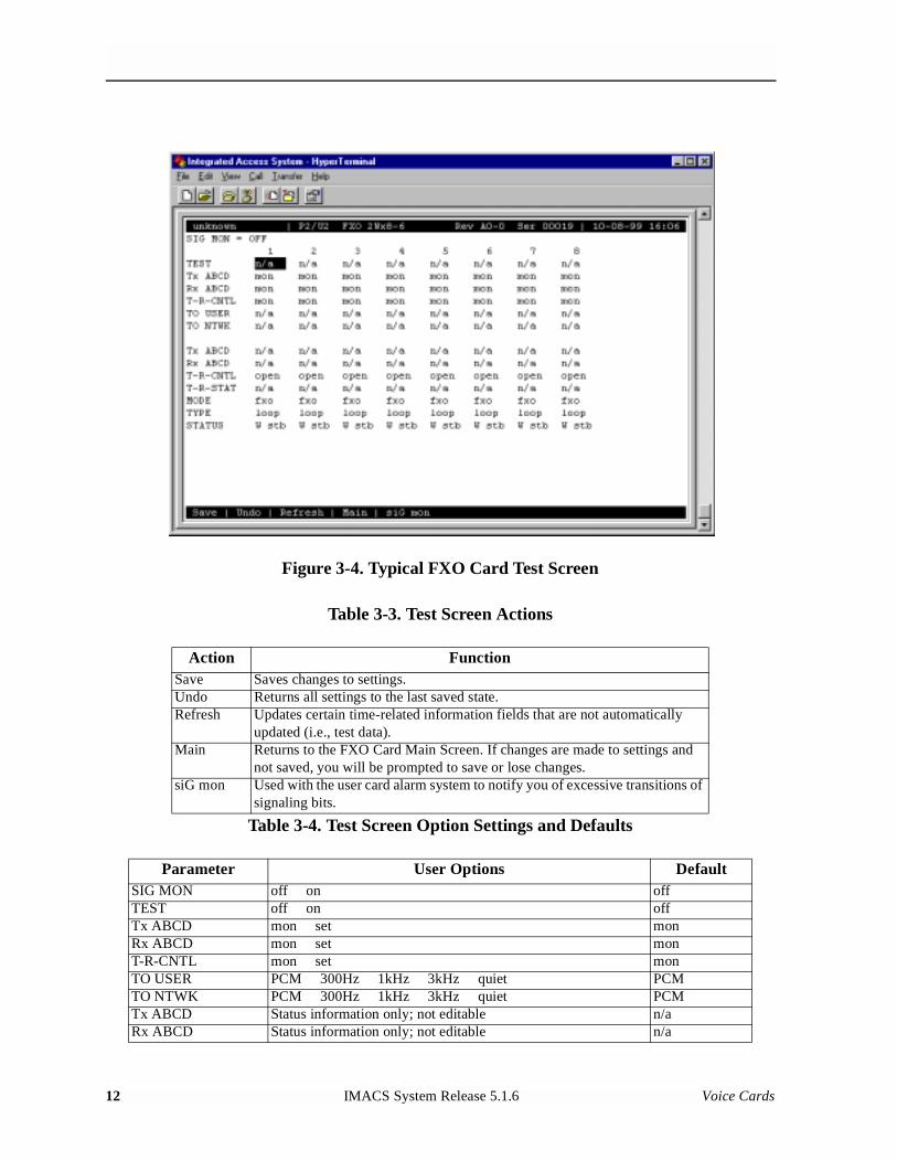
Model No.Running Head
Figure 3-4. Typical FXO Card Test Screen
Table 3-3. Test Screen Actions
Table 3-4. Test Screen Option Settings and Defaults
Action FunctionSave Saves changes to settings.Undo Returns all settings to the last saved state.Refresh Updates certain time-related information fields that are not automatically
updated (i.e., test data).Main Returns to the FXO Card Main Screen. If changes are made to settings and
not saved, you will be prompted to save or lose changes.siG mon Used with the user card alarm system to notify you of excessive transitions of
signaling bits.
Parameter User Options DefaultSIG MON off on offTEST off on offTx ABCD mon set monRx ABCD mon set monT-R-CNTL mon set monTO USER PCM 300Hz 1kHz 3kHz quiet PCMTO NTWK PCM 300Hz 1kHz 3kHz quiet PCMTx ABCD Status information only; not editable n/aRx ABCD Status information only; not editable n/a
12 IMACS System Release 5.1.6 Voice Cards
SIG MON
The Signaling Monitor feature works with the user card alarm system to detect excessive signaling bit transitions. The system will generate alarms if the number of transitions of any signaling bit in transmit or receive direction for an active port exceeds 255 in any four second interval. The options are off and on, and they are toggled by pressing “g” (siGmon command) in the Test Screen.
TEST
The Test Parameter shows if the port is in the test mode or not. Inactive ports and ports that are assigned to inactive WANs will show a test status of n/a. The test status options for active ports are off and on.
Tx ABCD
The Transmit ABCD setting allows you to either monitor the status of the ABCD signaling bits being transmitted towards the network or set a specific ABCD pattern for testing the transmit side of the circuit. The options for this field are mon (monitor) or set. Choosing set will bring up a four digit field for you to input the ABCD pattern you want to transmit. Any four digit combination of ones and zeros is acceptable for this setting.
Rx ABCD
The Receive ABCD setting allows you to either monitor the status of the ABCD signaling bits being received from the network, or set a specific ABCD pattern for testing the receive side of the circuit. The options for this field are mon (monitor) or set. Choosing set will bring up a four-digit field for you to input the ABCD pattern you want to receive. Any four digit combination of ones and zeros is acceptable for this setting.
T-R-CNTL
The Tip and Ring Control setting allows you to either monitor (mon) or set (set) the state of the Tip and Ring leads of an FXO port. Choosing set will bring up the following options:
• loop (the Tip and Ring leads are tied together)
• open (the Ring lead is not connected to either Tip or ground)
T-R-CNTL Status information only; not editable n/aT-R-STAT Status information only; not editable n/aMODE Status information only; not editable n/aTYPE Status information only; not editable n/aSTATUS Status information only; not editable n/a
Voice Cards IMACS System Release 5.1.6 13
Model No.Running Head
TO USER
In cross-connect systems only, the To User parameter allows you to break the circuit and send a test tone toward the user side of the system. The options for this field are PCM, 300Hz, 1 kHz, 3 kHz and quiet. Selecting PCM means that you do not want to inject a tone toward the user and that the PCM signal received from the network should continue to be sent to the user port in the normal manner.
TO NTWK
In cross-connect systems only, the To Network parameter allows you to break the circuit and send a test tone toward the network side of the system. The options for this field are PCM, 300Hz, 1 kHz, 3 kHz and quiet. Selecting PCM means that you do not want to inject a tone toward the network and that the PCM signal received from the user port should continue to be sent to the network in the normal manner.
Tx ABCD
The Transmit ABCD information field shows the current values of the ABCD bits that are being transmitted to the network. If TX ABCD in the top half of the screen is changed via the set function mentioned above, and the settings are saved by the Save command in the Menu of Actions, the new bit pattern chosen will be reflected here.
Rx ABCD
The Receive ABCD information field shows the current values of the ABCD signaling bits that are received from the network. If RX ABCD in the top half of the screen is changed via the set function mentioned above, and the settings are saved by the Save command in the Menu of Actions, the new bit pattern chosen will be reflected here.
T-R-CNTL
The Tip and Ring Control information field shows the current status of the Tip and Ring leads of the FXO port from the perspective of the system. The possible values are:
• loop (the Tip and Ring leads are tied together)
• open (the Ring lead is not connected to either the Tip or to ground)
• rgnd (the Ring lead is grounded)
• lpgnd (the Tip and Ring leads are tied together and the Tip is grounded)
• ring (ringing voltage is present on Tip and Ring)
14 IMACS System Release 5.1.6 Voice Cards
T-R-STAT
The Tip and Ring Status information field describes what the attached device is doing with the Tip and Ring leads of the FXO port. The possible values are:
• ring (attached device is applying ringing voltage between Tip and Ring)
• TbRg (attached device is applying -48V battery to Tip and grounding Ring)
• ToRo (attached device is leaving both the Tip and Ring leads open)
• TgRo (attached device is grounding the Tip lead and is leaving the Ring lead open)
• RbTg (attached device is applying -48V battery to Ring and grounding Tip)
• RbTo (attached device is applying -48V battery to Ring and leaving Tip open)
• TgR* (attached device is grounding Tip, and the Ring lead state is unknown)
• ToR* (attached device is leaving Tip open, and the Ring lead state is unknown)
• RoT* (attached device is leaving Ring open, and the Tip lead state is unknown)
• n/a (information is not available)
MODE
The Mode information field shows the current mode of the port that was selected on the main FXO card Screen. Valid settings are fxo, fxodn, dpt or mrd.
TYPE
The Type information field shows the current status of the signal field selected on the main FXO card screen for this port. Valid settings for both fxo and fxodn modes are loop (loop), gs (ground start), lp-fd (loop start-forward disconnect) and R2 (R2). Valid settings for the dpt mode are dpt (dial pulse terminating), R2 (R2), i-R2 (immediate R2), and dp-em (Dial Pulse Electromechanical). The only valid setting for the mrd mode is mrd (manual ringdown).
STATUS
The Status information field shows the current status of the port Table 3-5 lists and describes all of the possible conditions that are reported in this field.
Table 3-5. Status Information Field Settings
Setting Meaningstdby The FXO port is in standby.W stb The WAN card to which the FXO port is assigned is in standby.W tst The WAN card to which the FXO port is assigned is under test.W OOS The WAN card to which the FXO port is assigned is out of service.
Voice Cards IMACS System Release 5.1.6 15
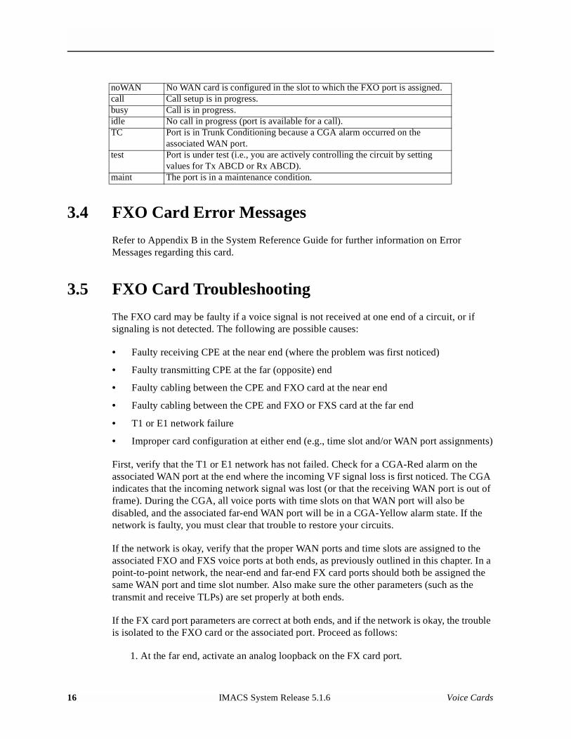
Model No.Running Head
3.4 FXO Card Error Messages
Refer to Appendix B in the System Reference Guide for further information on Error Messages regarding this card.
3.5 FXO Card Troubleshooting
The FXO card may be faulty if a voice signal is not received at one end of a circuit, or if signaling is not detected. The following are possible causes:
• Faulty receiving CPE at the near end (where the problem was first noticed)
• Faulty transmitting CPE at the far (opposite) end
• Faulty cabling between the CPE and FXO card at the near end
• Faulty cabling between the CPE and FXO or FXS card at the far end
• T1 or E1 network failure
• Improper card configuration at either end (e.g., time slot and/or WAN port assignments)
First, verify that the T1 or E1 network has not failed. Check for a CGA-Red alarm on the associated WAN port at the end where the incoming VF signal loss is first noticed. The CGA indicates that the incoming network signal was lost (or that the receiving WAN port is out of frame). During the CGA, all voice ports with time slots on that WAN port will also be disabled, and the associated far-end WAN port will be in a CGA-Yellow alarm state. If the network is faulty, you must clear that trouble to restore your circuits.
If the network is okay, verify that the proper WAN ports and time slots are assigned to the associated FXO and FXS voice ports at both ends, as previously outlined in this chapter. In a point-to-point network, the near-end and far-end FX card ports should both be assigned the same WAN port and time slot number. Also make sure the other parameters (such as the transmit and receive TLPs) are set properly at both ends.
If the FX card port parameters are correct at both ends, and if the network is okay, the trouble is isolated to the FXO card or the associated port. Proceed as follows:
1. At the far end, activate an analog loopback on the FX card port.
noWAN No WAN card is configured in the slot to which the FXO port is assigned.call Call setup is in progress.busy Call is in progress.idle No call in progress (port is available for a call).TC Port is in Trunk Conditioning because a CGA alarm occurred on the
associated WAN port.test Port is under test (i.e., you are actively controlling the circuit by setting
values for Tx ABCD or Rx ABCD).maint The port is in a maintenance condition.
16 IMACS System Release 5.1.6 Voice Cards

2. Send a 0 dBm (digital milliwatt) test signal toward the CPE at that end. That signal will be substituted for the normal signal coming from the far-end CPE; it will be sent back to the CPE at your end via the loopback path.
3. Check your CPE for this signal. If it is present, the far-end CPE or cabling to the far-end FX card is probably faulty. Disable the loopback and test signal there, and fix the problem. If you still don’t receive a signal, go to step 4.
4. At your end, go to the FXO Card Main Screen and send a digital milliwatt test tone (0 dBm) toward the CPE. If you still don’t receive a signal, check the cabling from the FXO card to your CPE, and check the CPE itself. If those items are okay, replace the FXO card at your end.
5. If the FXO card is determined to be faulty, replace it and return the faulty unit for repair to the location specified by your distributor.
3.6 FXO Card Specifications
FXO Cards (813970 2-wire)
Number of Ports8 ports
Physical InterfaceConnector 1 female 50-pin telco connector
Transmission PerformancePerformance Exceeds requirements of ITU-T Rec. G.713
Signaling ModesSignaling Modes Software selectable on a per port basis:
Foreign Exchange Office (FXO)Foreign Exchange Office- Defined Network (FXSDN)Manual Ringdown (MRD)Dial Pulse Termination (DPT)
Termination Impedance600 Ohms with 2.16 µF
VF Transmission CharacteristicsNominal Transmit TLP -10.0 dB to +5.0 dB in steps of 0.1 dBNominal Receive TLP -10.0 dB to +2.0 dB in steps of 0.1 dBPCM Encoding Software selectable on a per port basis
Attenuation Versus Frequency Relative to 1 kHz with 0 dBm0 inputFrequency Transmit (A to D) Receive (D to A)200 Hz -0.25 to +3.0 dB -0.25 to +2.0 dB300 to 3000 Hz -0.25 to +0.5 dB -0.25 to +0.5 dB3200 Hz 0.25 to +0.75 dB -0.25 to +0.75 dB3400 Hz -0.25 to +1.5 dB -0.25 to +1.5 dB
Return Loss (at 1 kHz) >28 dBTranshybrid Loss 34dBIdle Channel Noise (rcv and xmt) < -65 dBm0p Typ < -70 dBmop or < 20 dBrnc0
Voice Cards IMACS System Release 5.1.6 17
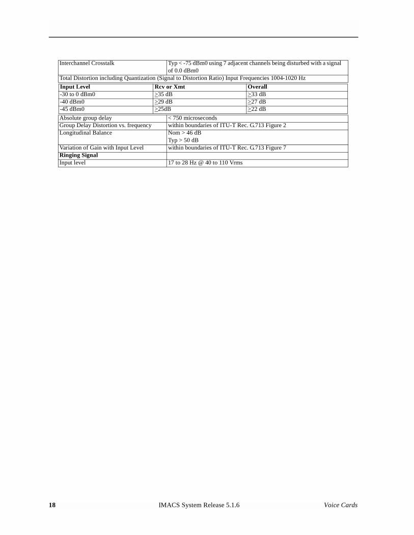
Model No.Running Head
Interchannel Crosstalk Typ < -75 dBm0 using 7 adjacent channels being disturbed with a signal of 0.0 dBm0
Total Distortion including Quantization (Signal to Distortion Ratio) Input Frequencies 1004-1020 Hz
Input Level Rcv or Xmt Overall-30 to 0 dBm0 >35 dB >33 dB-40 dBm0 >29 dB >27 dB-45 dBm0 >25dB >22 dB
Absolute group delay < 750 microsecondsGroup Delay Distortion vs. frequency within boundaries of ITU-T Rec. G.713 Figure 2Longitudinal Balance Nom > 46 dB
Typ > 50 dBVariation of Gain with Input Level within boundaries of ITU-T Rec. G.713 Figure 7Ringing SignalInput level 17 to 28 Hz @ 40 to 110 Vrms
18 IMACS System Release 5.1.6 Voice Cards