Embed Size (px)
Citation preview
CONTENTS - General Information
Ahaus GmbHvon-Braun-Straße 19aD-48683 AhausPostfach 1162 D-48661 AhausTelefon: +49(0) 2561-686-100Fax: +49(0) 2561-686-200
Register: 1
Page: 1
Date: 04.1995
Revision: 08.2010
Technical Manual
Summary of atomac valves ................................................................................... 2
Information on fluorcarbon resin lined valves ........................................................ 3
atomac ball valves with flourcarbon resin lining ................................................... 4
continuation ........................................................................................................... 5
General installation and maintenance instruction for
Fluorocopolymer - lined atomac valves ................................................................ 6
continuation ........................................................................................................... 7
Quality control according to DIN EN 9001 ............................................................. 8
EN-GJS-400-18U-LT (GGG-40.3) - nodular graphite iron ..................................... 9
EN-GJS-400-18U-LT (GGG-40.3) - comparison to foreign standards ................. 10
Specification EN-GJS-400-18U-LT (GGG-40.3) .................................................. 11
Stainless Steel (1.4408) - comparison to foreign standards ................................ 12
Specification Stainless Steel (1.4408) ................................................................. 13
Typical properties of atomac lining materials ....................................................... 14
Pressure-temperature-diagram ........................................................................... 15
Vacuum-temperature-diagram ............................................................................. 15
Product identification ........................................................................................... 16
Conversion of measuring units ............................................................................ 17
Operation Instruction, Gerneral Safety Information
.......................................................................................................Middle Europa
........................................................................................................South Europa
.......................................................................................................... North Europa
Section 1CONTENTS - General Information
Contents Page
CONTENTS - General Information
Ahaus GmbHvon-Braun-Straße 19aD-48683 AhausPostfach 1162 D-48661 AhausTelefon: +49(0) 2561-686-100Fax: +49(0) 2561-686-200
Register: 1
Page: 2
Date: 04.1995
Revision: 08.2010
Technical Manual
Overview of atomac valves
° DN ½“ and DN ¾“: Face-to-Face dimension DIN EN 558 (Basic series 1)* DN 150 and DN 200: Face-to-Face dimension ANSI B 16.10** DN 150: Face-to-Face dimension ANSI B 16.10 (short pattern)
ball valve face-to-face-dimension available siesatomac ball valve
AKH2 2-piece design DINEN 1092-PN 16 DIN EN 558 DN 15 - DN 200 / 150full bore DINEN 1092-PN 16 DIN EN 558 DN 200, 250, 300, 350
ANSIB 16.5 -150lbs ANSI B 16.10 ° DN ½“ - DN 14“
AKH2 300lbs 2-piece design DINEN 1092-PN 16 DIN EN 558 DN 1“ - DN 6“full bore DINEN 1092-PN 16 DIN EN 558
ANSIB 16.5 -300lbs ANSI B 16.10 °
AKH2A 2-piece design ANSI B 16.5 -150lbs ISO 5752, Tab.6,short DN 1“ - DN 6“full bore ANSI B 16.10, short
AKH3 2-piece design ANSI B 16.5 -150lbs ISO 5752, Tab.6,short DN 1“ - DN 12“venturi port ANSI B 16.10, short
JISB 2220 -10 K ANSI B 16.10, short DN 20 - DN 150
AKH5 2-piece design DINEN 1092-PN 16 DIN EN 558 DN 25 - DN 100with ceramic insert ANSIB 16.5 -150lbs DN 1“ - DN 4“
AKH6 2-piece design DIN EN 1092-PN 16 DN 25/50 - DN 150/200vessel drain valve ANSIB 16.5 -150lbs DN 1“/2“ - DN 6“/8“
AKH7/GK glass connection / short face to face DN 25, 40, 50
AKH7/KP glass connection DINglass ends: DIN EN 12585 DN 25, 40, 50, 100
AKH7/KPF glass connection DINglass ends: DIN EN 12585 DN 25, 40, 50, 100
AKH7/KP glass connection 3 bolt flange connection DN 25, 40, 50
AKH8 2-piece design DN15 - DN 100with monoblock
AKH2.2 2-piece design DINEN 1092-PN 16 DIN EN 558 ° DN 15 - DN 100ANSIB 16.5 -150lbs DN½“ - DN 4“
AS1 2-piece design DINEN 1092-PN 16 DIN EN 558 DN 15 - DN 150full bore
AS2 2-piece design ANSIB 16.5 -150lbs ° DN ¾“ - DN 6“full bore
AS3 2-piece design ANSI B 16.5 -150lbs ISO 5752, Tab.6,short DN ½“ - DN 6“full bore ANSI B 16.10, short
AS4 2-piece design JISB 2220 -10 K ANSI B 16.10, short DN 15 - DN 150full bore
AS5 2-piece design JISB 2220 -10 K DN 15 - DN 100full bore
AS6 2-piece design JISB 2220 -10 K DN 1“ - DN 8“full borewith heating jacket
AMP3 2-piece design DINEN 1092-PN 16 DIN EN 558 DN 25 - DN 150ANSIB 16.5 -150lbs DIN EN 558 DN 1“ - DN 6“
atomac check valveARV 2-piece design DINEN 1092-PN 16 DIN EN 558 * DN 15 - DN 200
ANSIB 16.5 -150lbs DN ½“ - DN 8“
ARL DIN EN1092-2 -PN 16 DIN EN 558 DN 25, 40, 50, 80 ANSIB 16.5 -150lbs DIN EN 558 DN 1“ - DN 3“
atomac check valveARK2 DIN1092-2 -PN 16 DIN EN 558 series 20 DN 50 - 400
ANSIB 16.5 -150lbs ANSI B 16.10 Tab.9 Sp.3 DN 2“ - DN 16“
atomac sight glassASG DIN EN 1092-PN 16 DIN EN 558 DN 25 - DN 250
ANSIB 16.5 -150 lbs DN 1“ - DN 10“
ASG/B vessel sight glass DINEN 1092-PN 10 DN 80 - DN 200
ARV/SG DINEN 1092-PN 16 DIN EN 558 DN 25 - DN 150ANSIB 16.5 -150lbs DN 1“ - DN 4“
APN/SG sampling valve - sight glass DINEN 1092-PN16 DIN EN 558 DN 25, 40, 50, 80ANSIB 16.5 -150lbs DN 1“, 1½“, 2“, 3“
ASG3 DINEN 1092-PN 16 DIN EN 558 DN 25, 40, 50, 80
atomac sampling valveAtoPro sampling valve DN 25 - DN 80
DN 1“ - DN 3“
APN T- form DINEN 1092-PN16 DIN EN 558 DN 25, 50, 80sight glass DINEN 1092-PN16 DIN EN 558 DN 25, 40, 50, 80
ANSIB 16.5 -150 lbs DN 1“ - DN 3“
atomac strainerASF DINEN 1092-PN 16 DIN EN 558 * DN 25 - DN 200
ANSIB 16.5 -150lbs ANSI B 16.10 DN 1“ - DN 8“
atomac sleevelineT4E1 ANSIB 16.5 -150lbs ANSI B 16.10, short DN ½“ - DN 12“
T4E2 DINEN 1092-PN16 DIN EN 558** DN 15 - DN 150DINEN 1092-PN10 ANSI B 16.10, short DN 200 - DN 300
T4E3 ANSIB 16.5 -300lbs DIN EN 558 DN ½“ - DN 8“
CONTENTS - General Information
Ahaus GmbHvon-Braun-Straße 19aD-48683 AhausPostfach 1162 D-48661 AhausTelefon: +49(0) 2561-686-100Fax: +49(0) 2561-686-200
Register: 1
Page: 3
Date: 04.1995
Revision: 08.2010
Technical Manual
Information on Fluorcopolymer*-lined atomac ball valves
Fluorcopolymer-lined valves consist of different materials combining the good mechanical proper-ties of ductile iron with the high corrosion resistance of fluorcopolymer.Fluorcarbon resins are resistant to a variety of chemical process media. They can be used without any problems in applications where extremely acid and alcaline fluids are used. They allow for the transport of different fluids, changes in process and change-overs to other products, without having to change the valve. Due to their low slippage resistance and to their non-stick properties, fluorcopolymer-lined valves have an extremely low friction. Even when the line media is slurry, highly viscous or adhesive, the fluorocarbon resin liner prevents the equipment from becoming plugged and allows for easy clea-ning. The fluorocarbon resin linings in atomac ball valves are free from pores and are resistant to galvanic corrosion. They are insensitive to thermal and mechanical shocks.Manufacture of atomac ball valves is subject to the very strict quality control standards according to DIN EN ISO 9001. Permanent controls of the materials used and of production processes assu-re the consistantly good quality of atomac ball valves.Due to their technically high-standard production process, atomac ball valves are supremely eco-nomical and reliable. This is proven by their applications in chemical, petrochemical, pharmaceu-tical, cosmetic and food processing industries. Furthermore, fluorcopolymer-lined atomac ball valves are successfull in salt mines and with desalination and water treatment industries. They are also used in other processes where extremely aggressive, corrosive, toxic and other critical fluids have to be handled. Due to their corrosion resistance and to their reliability, atomac ball valves provide a maximum protection for people, environment and production.Fluorcopolymer-lined atomac ball valves are available in DIN-as well as ANSI and JIS versions.
DELIVERY CONDITION
All atomac ball valves are delivered with a flange protection cap at their flanges in order to pro-tect sealing faces during transport. These protection caps must not be removed until immediately before installation.
CONTROL AND CERTIFICATES
Inspection test certificates according to EN 10204 - 3.1 and EN 10204 - 2.2, for casting, lining material, leakage and strength test, can be issued. When an order is placed, the type of certificate, if required, must be specified. The strength test of fluorcopolymer-lined ball valves is carried out according to DIN DIN EN 12266-1 (P10) and for ANSI-valves according to API 598; the leakage test is carried out according to DIN EN 12266-1 (leak rate A).
The pysical properties of the fluorcarbon resins are tested during incoming inspection for the indi-cations made by the raw material manufacturers according to DIN, ANSI and ASTM standards.
BODY SURFACES PROTECTION
As standard, atomac ball valves are delivered with a two-layer acrylic-base primer with a mini-mum thickness of 60 mm. Upon request, other paintings are possible.
* also available with PP (Polypropylene)-lining
CONTENTS - General Information
Ahaus GmbHvon-Braun-Straße 19aD-48683 AhausPostfach 1162 D-48661 AhausTelefon: +49(0) 2561-686-100Fax: +49(0) 2561-686-200
Register: 1
Page: 4
Date: 04.1995
Revision: 08.2010
Technical Manual
atomac ball valves with fluorocopolymer* lining
* also available with PP (polypropylene)-lining
atomac ball valves have all the inherent design features of a conventional ball valve:
full port in the main sizes, low pressure drop, low torque, quarter-turn operation. Furthermore, ato-mac ball valves offer a nearly universal corrosion resistance and a high degree of safety.
The most important design features of the atomac ball valve are the following:
1.) Lining of all interior body surfaces, i.e. all valve parts being in contact with medium are fluo-rocopolymer-lined.
2.) The positive retention of the lining material on the body, ball and stem. Because of this, a high vacuum rating is provided.
3.) Due to the fact that ball and stem are separately positioned (floating ball system), the floa-ting ball seals against the downstream seat ring even when line pressure is low. For this reason, an early and perfect sealing in the port of the valve is assured. Furthermore, this systems prevents leverages on the stem.
4.) The fluorocopolymer-lined stem (material 1.4470 or ASTM A789) is protected through a metallic bond inside the valve against blow-out. This anti-blow-out stem represents an additional means of safety.
5.) The gland follower is not a new idea, but through the use of PTFE chevron packing rings extremely efficient. The vertical pressure on the packing is converted to horizontal expan-sion without any shearing effect. The gland follower can be adjusted without impairing the function of the stem.
6.) atomac ball valves are manufactured according to DIN/ISO 9001. For example all fluoroco-
polymer-lined parts are 100% high voltage spark tested, in order to discover possible damage or cracks.
CONTENTS - General Information
Ahaus GmbHvon-Braun-Straße 19aD-48683 AhausPostfach 1162 D-48661 AhausTelefon: +49(0) 2561-686-100Fax: +49(0) 2561-686-200
Register: 1
Page: 5
Date: 04.1995
Revision: 08.2010
Technical Manual
The tightness of the valves is checked according to API 598 or DIN EN 12266-1.
Due to their simplicity and inherent strength, atomac ball valves are virtually maintenance free. Because of their prolonged service life expectance, they prove to be very economical, even under extreme service conditions.
Fitment of an actuator is very simple:By means of an adequate bracket (DIN EN ISO 5211) and adaptor, all types of actuators can be fitted within a few minutes without removing the valve from the line.
As a standard, the atomac ball valve is provided with a grounding device.
STORAGE AND INSTALLATION
Contrary to pure steel ball valves, fully lined ball valves and all other atomac valves require a high degree of care as far as packing, transport, storage and installation is concerned, as the corrosion resistance of the valve is largely dependant on the integrity of the lining.Therefore it is advisable to avoid damages to the lining caused by blows, shocks or ingress of sand or metal chip etc. onto the sealing faces of the flanges.
Please consider our installation instructions for lined ball valves!
CONTENTS - General Information
Ahaus GmbHvon-Braun-Straße 19aD-48683 AhausPostfach 1162 D-48661 AhausTelefon: +49(0) 2561-686-100Fax: +49(0) 2561-686-200
Register: 1
Page: 6
Date: 04.1995
Revision: 08.2010
Technical Manual
General installation and maintenance instruction for fluorcopolymer-lined atomac ball valves
Fluorcarbon resin lined valves cannot be treated in the same way as unlined steel valves. The lining material is softer and more sensitive than metal and is subject to cold flow. If only one tiny spot of the lining materials is damaged, this could result in leakage or damage to the metal body by the medium. It is essential for all atomac valves that before start-up of a new plant the piping system is being flushed in order to remove possible solids such as welding beads, sand, etc. The valves (atomac ball) valves must be 100% open during the flushing process to avoid that impuriti-es settle between the seatrings and the ball which could cause damages when the valve is opera-ted. The lining material moves under temperature and pressure, in that it expands and shrinks. This means that in practical applications all data given for lined valves must be seen in relation to cer-tain conditions of temperature and pressure.
For the handling of atomac valves, we are giving you the following guidelines:
1.) Lined valves have soft sealing faces. Therefore, the flange protection caps intended for transport and storage must not be removed until immediately before installation. Should it prove necessary to remove the protection caps for inspection purposes, care must be taken to re-fit them into their original position upon completion of the inspection.
2.) If the flange protection caps are removed, fittings must never be placed so as to rest on
the soft sealing faces. If this cannot be avoided, care must be taken to keep the workbench clean and free of metal chip, sand or other solid particles.
3.) No additional gaskets are required for the installation of atomac lined valves.
4.) For maintenance work on an atomac ball valve installed in a pipeline, the works safety requirements and the general accident prevention instructions are to be observed. Look for contact between stem , grounding spring and gland follower.
5.) 2 - 5 hours after the installation has reached its final operating temperature, flange bolts must be retightened in accordance with the corresponding torque values (see standard valve chart of the respective valve). Should any leakage occur, it is recommended to check by means of a torque wrench that the tension bolts have been tightened evenly. If this is the case, the nut of the tension bolt which is closest to the area where leakage is occuring must be tightened with a 45-degree turn. The 45-degree turns may then be repeated until the val-ve leak is eliminated. However, where,ball valves are concerned, the valve must be opera-ted after every 90-degree turn of the nut to make sure that the ball valve can be opened and closed without problems. If leakage has been eliminated by this method, then all remaining bolts on the same side of the fitting must be tightened by means of a torque wrench. Finally the valve must be operated to check its performance.
6.) After lengthy operation period, leakage may occur in the stem area due to normal wear and tear of the material. In such a case, the adjusting nuts above the gland follower must be tightened evenly with short turns until leakage stops. An uneven tightening of the packing gland follower can result in a tilting of the same. Every time that the packing gland follower has been re-adjusted, a test must be carried out to establish that the ball valve still opens and closes smoothly.
CONTENTS - General Information
Ahaus GmbHvon-Braun-Straße 19aD-48683 AhausPostfach 1162 D-48661 AhausTelefon: +49(0) 2561-686-100Fax: +49(0) 2561-686-200
Register: 1
Page: 7
Date: 04.1995
Revision: 08.2010
Technical Manual
CAUTION
Excessive tightening of the adjusting nuts might damage the stem lining. The packing gland follower must only be adjusted to such a degree as is required for the elimination of the leak.
7.) If the above measures do not succeed in stopping the leakage, it is recommended to return the valve to the manufacturer in order to have the valve checked and to eliminate the problem. For security reasons, it is absolutely necessary to decontaminate the valve. The user has to confirm the decontamination by fixing a return goods tag on the valve. Before returning the valve, the procedure must be coordinated with atomac sales.
8.) If, for any reason, an atomac ball valve becomes difficult to operate or jams, you must not use a hammer on the hand lever or extend the hand lever with pipe pieces. Such a procedure may lead to damage of ball and/or stem and invalidates any guarantees.
atomac valves are manufactured, assembled and tested with the utmost care according to DIN EN ISO 9001. Continuous quality controls make sure that defects are reduced to a minimum. This and an adequate handling of the valves during transportation, storage, installation and main-tenance will ensure a long service life and many trouble-free hours of operation.
CONTENTS - General Information
Ahaus GmbHvon-Braun-Straße 19aD-48683 AhausPostfach 1162 D-48661 AhausTelefon: +49(0) 2561-686-100Fax: +49(0) 2561-686-200
Register: 1
Page: 8
Date: 04.1995
Revision: 08.2010
Technical Manual
Quality Assurance Lloyd‘s Certificate no. 910027 acc. to DIN EN ISO 9001 - 2000
ANSI / ASQC Q 9001 - 2000
The QA system is developed to meet the ISO 9001. All atomac valves are checked and tested according to the Quality Assurance procedures set out below. On request of the customer, this will be confirmed by certificates and test reports.
1. Goods Received
1.1 Visual check of castings for cavities, burrs and sunk spots as well as control of marking for completeness and readability.1.2 Dimensional inspection with reference to drawings and patterns (at random). 1.3 Verification of the mechanical values of the lining material.
2. Manufacturing Control
2.1 Checking of castings for dimensional accuracy and surface quality (at random).2.2 Checking of all surfaces coming into contact with the lining material for cleanliness. 2.3 Checking of lining (all parts).2.3.1 Checking of lining thickness by means of a stratum thickness measuring instrument.2.3.2 Checking of lining for bubbles, cracks and foreign body enclosures.2.3.3 High voltage spark test according to the formula: 6 (1+material thickness in mm) KV.2.4 Checking of the outside coating of Acrylic (at random).2.4.1 Checking of outside coating on request of customer.
3. Assembly Control
3.1 Random test of face-to-face and other dimensions.3.2 Tightness test acc. to DIN EN 12266-1 (P10).3.3 Pressure test acc. to DIN EN 12266-1 (leak rate A).
4. Shipping Control
4.1 Checking of identification tags and marking (special markings can be arranged to customer‘s specification).4.2 Checking of flange protection caps.4.3 Checking of shipping instructions and packing.
5. Test Reports and Certificates
5.1 Check of body and lining materials.5.2 Check for tightness and strength.5.3 Test certificates for body and lining (EN 10204-2.2 or 3.1).5.4 Pressure test report. Approval test report (work approval).5.5 Approval by the customer.
CONTENTS - General Information
Ahaus GmbHvon-Braun-Straße 19aD-48683 AhausPostfach 1162 D-48661 AhausTelefon: +49(0) 2561-686-100Fax: +49(0) 2561-686-200
Register: 1
Page: 9
Date: 04.1995
Revision: 08.2010
Technical Manual
Nodular Graphite Iron EN-GJS-400-18U-LT (GGG-40.3)
EN-GJS-400-18U-LT (GGG-40.3) DIN EN 1563 (comparable to DI-A 395/ASTM 395) Material No.: EN-JS1049 (0.7043)
Definition acc. to DIN EN 1563, part II, is the following:
„Nodular graphite iron is an iron-carbon casting material, of which the
quantily of carbon consisting of graphitehas a nearly completely nodular from.“
For the melting of this material, electric and induction furnaces are common. Sometimes however, shaft and cupola melting furnaces can be used. As charge materials, special kinds of raw iron and selected quality steel scrap are used. In order to obtain this nodular graphite iron, small quantities of master alloy magnesium or pure magnesium are given to the melting charge. Depending on the chemical composition of the melting charge and on the rate of cooling, solidification of the material is either ferritic/pearlitic, pearlitic or, as desired, ferritic as cast. The ferritic basic structure is also obtained through a ferritic thermal treatment. Advantages of this material: mechancial values being similar to those of steel together with a good processibility. In order to determine the mechanical values, the sample pieces can be integrally or separately cast (EN 1563).
EN-GJS-400-18U-LT (GGG-40.3) represents a special ferritic form of nodular graphite iron with a guaranteed notched bar impact. According to AD-Merkblatt W 3/2, for a temperature rangeof -10°C to 350°C.
In stress case II, the thermal treated material can be used with a temperature of max. -60°C with 75% of the admissible apparent yielding point (AD-Merkblatt W 10).
All foundries working for Flowserve Corporation have the TÜV approval according to TRD 100/WO. Differing from EN 1563, all body parts form EN-GJS-400-18U-LT (GGG-40.3) material purchased by atomac correspond at the same time to the strict technical delivery conditions of the „Verband der Chemischen Industrie“ (VCI) (federation of the chemical industry).
CONTENTS - General Information
Ahaus GmbHvon-Braun-Straße 19aD-48683 AhausPostfach 1162 D-48661 AhausTelefon: +49(0) 2561-686-100Fax: +49(0) 2561-686-200
Register: 1
Page: 10
Date: 04.1995
Revision: 08.2010
Technical Manual
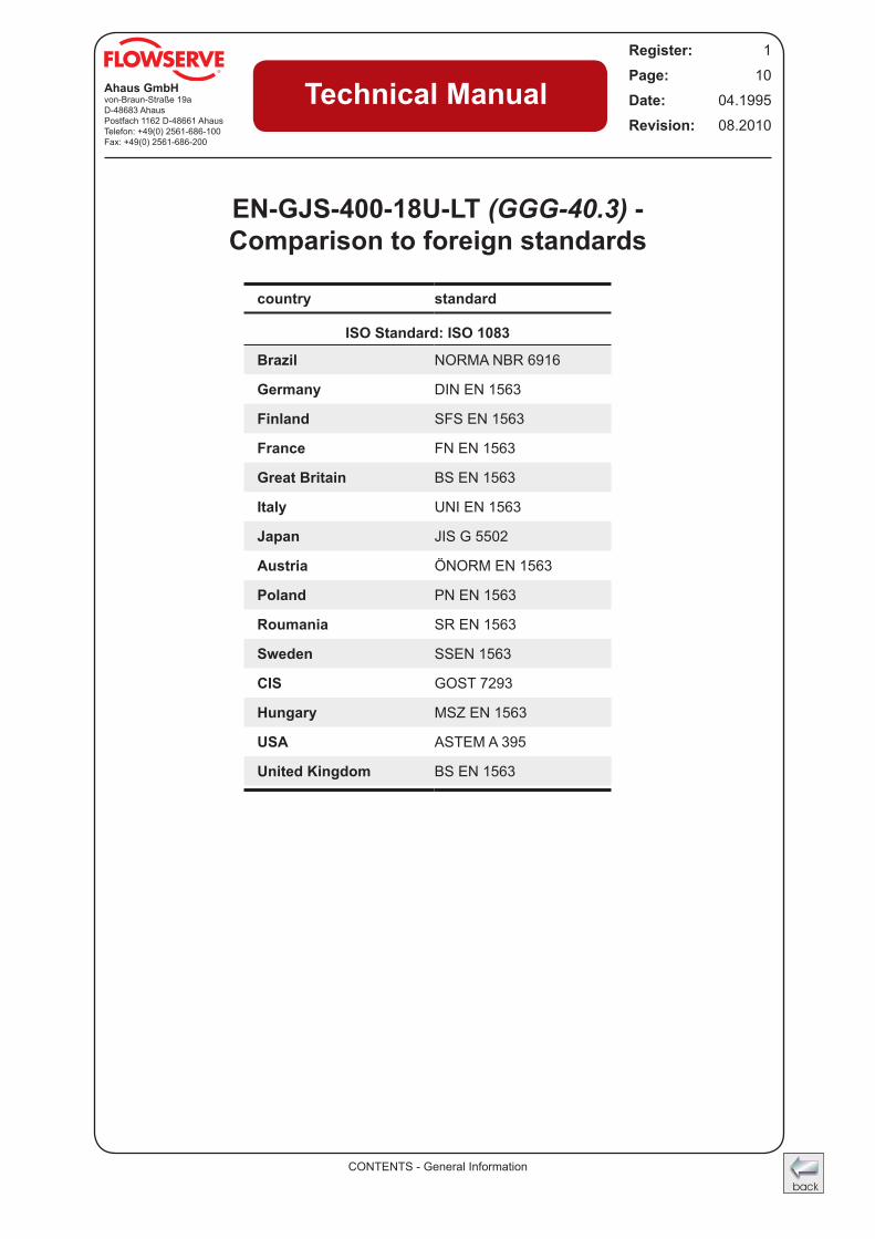
EN-GJS-400-18U-LT (GGG-40.3) - Comparison to foreign standards
country standard
ISO Standard: ISO 1083
Brazil NORMA NBR 6916
Germany DIN EN 1563
Finland SFS EN 1563
France FN EN 1563
Great Britain BS EN 1563
Italy UNI EN 1563
Japan JIS G 5502
Austria ÖNORM EN 1563
Poland PN EN 1563
Roumania SR EN 1563
Sweden SSEN 1563
CIS GOST 7293
Hungary MSZ EN 1563
USA ASTEM A 395
United Kingdom BS EN 1563
CONTENTS - General Information
Ahaus GmbHvon-Braun-Straße 19aD-48683 AhausPostfach 1162 D-48661 AhausTelefon: +49(0) 2561-686-100Fax: +49(0) 2561-686-200
Register: 1
Page: 11
Date: 04.1995
Revision: 08.2010
Technical Manual
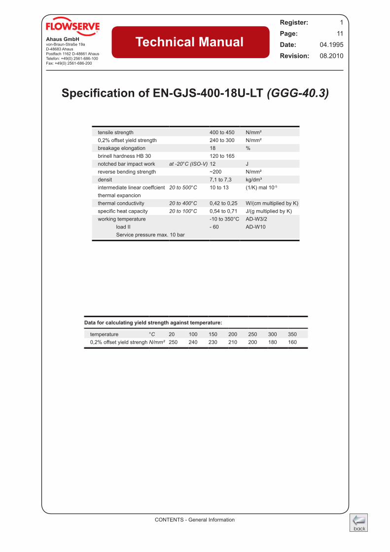
Specification of EN-GJS-400-18U-LT (GGG-40.3)
tensile strength 400 to 450 N/mm²0,2% offset yield strength 240 to 300 N/mm²breakage elongation 18 %brinell hardness HB 30 120 to 165notched bar impact work at -20°C (ISO-V) 12 Jreverse bending strength ~200 N/mm²densit 7,1 to 7,3 kg/dm³intermediate linear coeffcient 20 to 500°C 10 to 13 (1/K) mal 10-5
thermal expancionthermal conductivity 20 to 400°C 0,42 to 0,25 W/(cm multiplied by K)specific heat capacity 20 to 100°C 0,54 to 0,71 J/(g multiplied by K)working temperature -10 to 350°C AD-W3/2
load II - 60 AD-W10Service pressure max. 10 bar
Data for calculating yield strength against temperature:
temperature °C 20 100 150 200 250 300 350 0,2% offset yield strengh N/mm² 250 240 230 210 200 180 160
CONTENTS - General Information
Ahaus GmbHvon-Braun-Straße 19aD-48683 AhausPostfach 1162 D-48661 AhausTelefon: +49(0) 2561-686-100Fax: +49(0) 2561-686-200
Register: 1
Page: 12
Date: 04.1995
Revision: 08.2010
Technical Manual
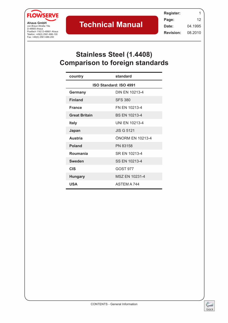
Stainless Steel (1.4408) Comparison to foreign standards
country standard
ISO Standard: ISO 4991
Germany DIN EN 10213-4
Finland SFS 380
France FN EN 10213-4
Great Britain BS EN 10213-4
Italy UNI EN 10213-4
Japan JIS G 5121
Austria ÖNORM EN 10213-4
Poland PN 83158
Roumania SR EN 10213-4
Sweden SS EN 10213-4
CIS GOST 977
Hungary MSZ EN 10231-4
USA ASTEM A 744
CONTENTS - General Information
Ahaus GmbHvon-Braun-Straße 19aD-48683 AhausPostfach 1162 D-48661 AhausTelefon: +49(0) 2561-686-100Fax: +49(0) 2561-686-200
Register: 1
Page: 13
Date: 04.1995
Revision: 08.2010
Technical Manual
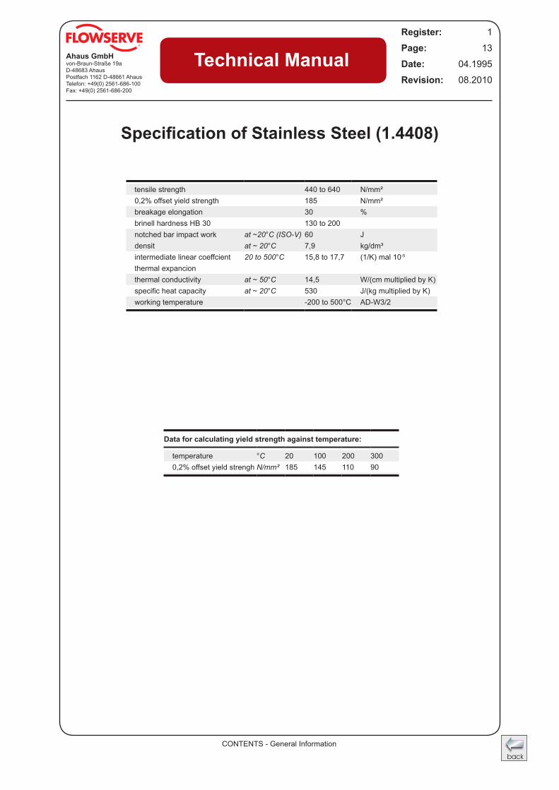
Specification of Stainless Steel (1.4408)
tensile strength 440 to 640 N/mm²0,2% offset yield strength 185 N/mm²breakage elongation 30 %brinell hardness HB 30 130 to 200notched bar impact work at ~20°C (ISO-V) 60 Jdensit at ~ 20°C 7,9 kg/dm³intermediate linear coeffcient 20 to 500°C 15,8 to 17,7 (1/K) mal 10-5
thermal expancionthermal conductivity at ~ 50°C 14,5 W/(cm multiplied by K)specific heat capacity at ~ 20°C 530 J/(kg multiplied by K)working temperature -200 to 500°C AD-W3/2
Data for calculating yield strength against temperature:
temperature °C 20 100 200 300 0,2% offset yield strengh N/mm² 185 145 110 90
CONTENTS - General Information
Ahaus GmbHvon-Braun-Straße 19aD-48683 AhausPostfach 1162 D-48661 AhausTelefon: +49(0) 2561-686-100Fax: +49(0) 2561-686-200
Register: 1
Page: 14
Date: 04.1995
Revision: 08.2010
Technical Manual
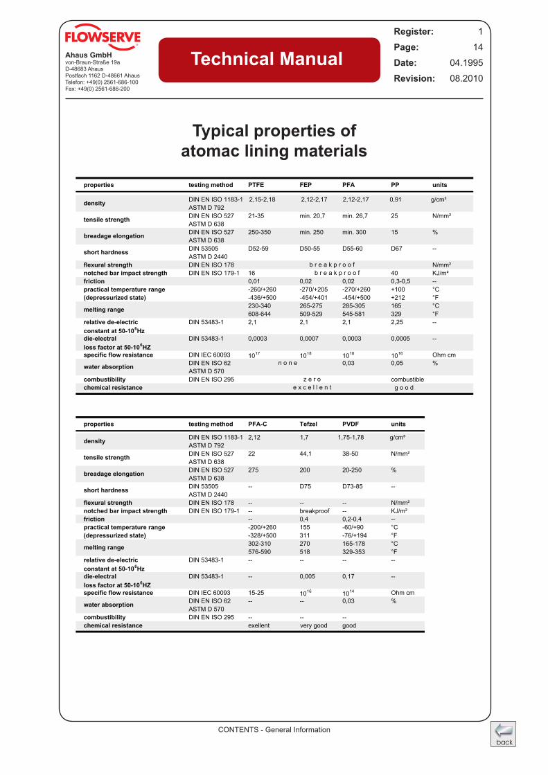
Typical properties ofatomac lining materials
EN ISO 1183-1 2 2 0 g
EN ISO 1183-1 2 1,7 1 g
CONTENTS - General Information
Ahaus GmbHvon-Braun-Straße 19aD-48683 AhausPostfach 1162 D-48661 AhausTelefon: +49(0) 2561-686-100Fax: +49(0) 2561-686-200
Register: 1
Page: 15
Date: 04.1995
Revision: 08.2010
Technical Manual
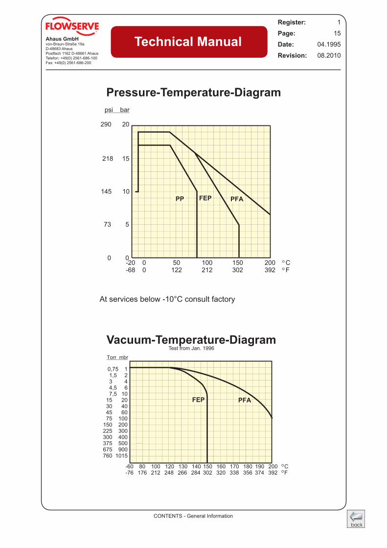
Pressure-Temperature-Diagram
Vacuum-Temperature-DiagramTest from Jan. 1996
At services below -10°C consult factory
psi bar
290 20
218 15
145 10
73 5
0 0
PP FEP
-20 0 50 100 150 200 �C-68 0 122 212 302 392 �F
PFA
Torr mbr
0,75 11,5 23 44,5 67,5 10
15 2030 4045 6075 100
150 200225 300300 400375 500675 900760 1015
-60 80 100 120 130 140 150 160 170 180 190 200 C-76 176 212 248 266 284 302 320 338 356 374 392 F
FEP PFA
°
°
°
°
CONTENTS - General Information
Ahaus GmbHvon-Braun-Straße 19aD-48683 AhausPostfach 1162 D-48661 AhausTelefon: +49(0) 2561-686-100Fax: +49(0) 2561-686-200
Register: 1
Page: 16
Date: 04.1995
Revision: 08.2010
Technical Manual
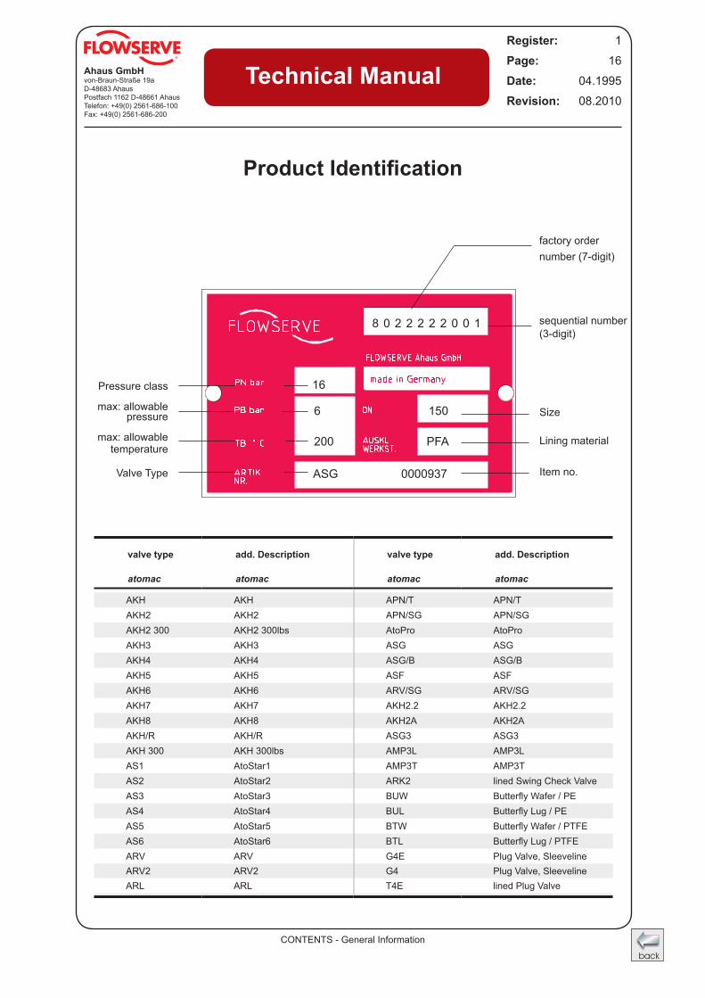
Product Identification
factory order number (7-digit)
sequential number (3-digit)
Size
Lining material
Item no.
8 0 2 2 2 2 2 0 0 1
ASG 0000937
200 PFA
6 150
16Pressure class
max: allowable pressure
max: allowable temperature
Valve Type
valve type add. Description valve type add. Description
atomac atomac atomac atomac
AKH AKH APN/T APN/TAKH2 AKH2 APN/SG APN/SGAKH2 300 AKH2 300lbs AtoPro AtoProAKH3 AKH3 ASG ASGAKH4 AKH4 ASG/B ASG/BAKH5 AKH5 ASF ASFAKH6 AKH6 ARV/SG ARV/SGAKH7 AKH7 AKH2.2 AKH2.2AKH8 AKH8 AKH2A AKH2AAKH/R AKH/R ASG3 ASG3AKH 300 AKH 300lbs AMP3L AMP3LAS1 AtoStar1 AMP3T AMP3TAS2 AtoStar2 ARK2 lined Swing Check ValveAS3 AtoStar3 BUW Butterfly Wafer / PEAS4 AtoStar4 BUL Butterfly Lug / PEAS5 AtoStar5 BTW Butterfly Wafer / PTFEAS6 AtoStar6 BTL Butterfly Lug / PTFEARV ARV G4E Plug Valve, SleevelineARV2 ARV2 G4 Plug Valve, SleevelineARL ARL T4E lined Plug Valve
CONTENTS - General Information
Ahaus GmbHvon-Braun-Straße 19aD-48683 AhausPostfach 1162 D-48661 AhausTelefon: +49(0) 2561-686-100Fax: +49(0) 2561-686-200
Register: 1
Page: 17
Date: 04.1995
Revision: 08.2010
Technical Manual
Conversions
To start the conversion, please click the buttom below.You have following conversion options:
Index Card
FlowForceLightMassPowerPressureSpeed
AccelerationAngleAreaDensityDistance
TemperatureTimeVolume, Volume-DryEnergy
GB
F
NL
B D
CH A
IRL
L
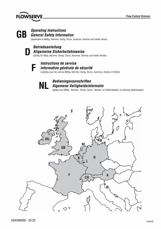
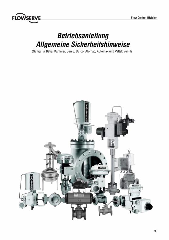
Operating InstructionsGeneral Safety Information
ADK096000 - 03.02
Flow Control Division
(applicable to Bättig, Kämmer, Sereg, Durco, Automax, Atomac and Valtek valves)
BetriebsanleitungAllgemeine Sicherheitshinweise(Gültig für Bätig, Kämmer, Sereg, Durco, Automax, Atomac und Valtek Ventile)
GB
D
F
NL
Instructions de serviceInformation générale de sécurité(valables pour les vannes Bättig, Kämmer, Sereg, Durco, Automax, Atomac et Valtek)
BedieningsvoorschriftenAlgemene Veiligheidsinformatie(geldig voor Bättig-, Kämmer-, Sereg-, Durco-, Atomac- en Valtek-kleppen, en Automax aandrijvingen)
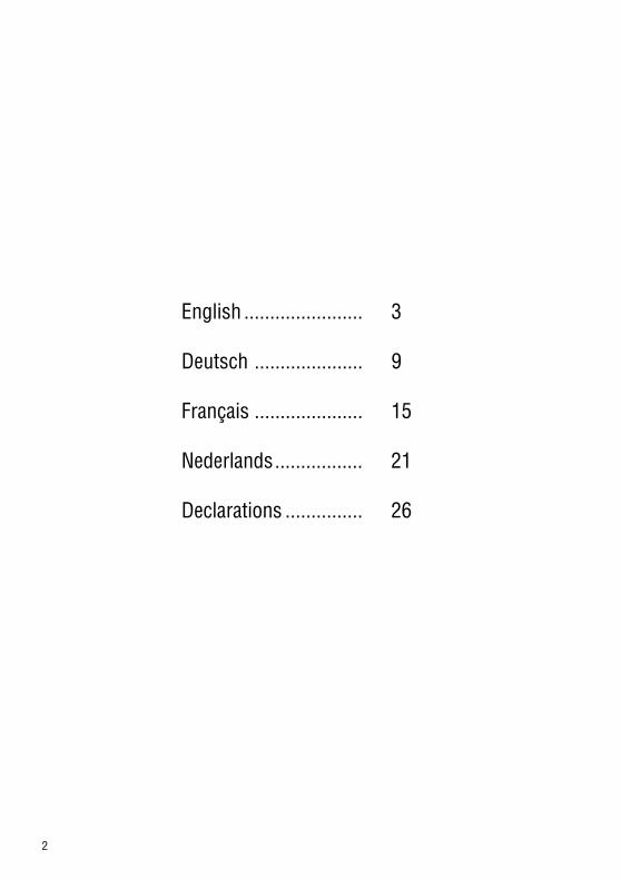
2
English ....................... 3
Deutsch ..................... 9
Français ..................... 15
Nederlands................. 21
Declarations ............... 26
3
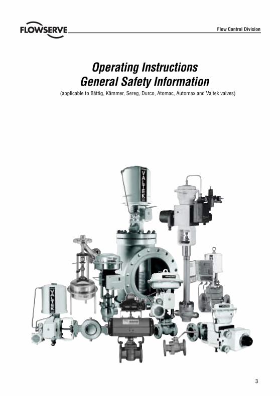
Operating InstructionsGeneral Safety Information
(applicable to Bättig, Kämmer, Sereg, Durco, Atomac, Automax and Valtek valves)
Flow Control Division

4
USING FLOWSERVE VALVES AND ACTUATORS CORRECTLY
Terms concerning safety
The safety terms DANGER, WARNING, CAUTION and NOTE are used in these instructions to highlight particulardangers and/or to provide additional information on aspects that may not be readily apparent.
DANGER: indicates that death, severe personal injury and/or substantial property damage will occurif proper precautions are not taken.
WARNING: indicates that death, severe personal injury and/or substantial property damage canoccur if proper precautions are not taken.
CAUTION: indicates that minor personal injury and/or property damage can occur if proper precautionsare not taken.
NOTE: indicates and provides additional technical information, which may not be very obvious evento qualified personnel.Compliance with other, not particularly emphasised notes, with regard totransport, assembly, operation and maintenance and with regard to technical documentation (e.g.in the operating instruction, product documentation or on the product itself) is essential, in order toavoid faults, which in themselves might directly or indirectly cause severe personal injury or propertydamage.
Using
The following instructions are designed to assist in unpacking, installing and performing maintenance asrequired on FLOWSERVE products. Product users and maintenance personnel should thoroughly review thisbulletin prior to installing, operating or performing any maintenance.
DANGER: In most cases FLOWSERVE valves and actuators are designed for specific applications(e.g. with regard to medium, pressure, temperature). For this reason they should not be used inother applications without first consulting the manufacturer.
Protective clothing
FLOWSERVE products are often used in problematic applications (e.g. extremely high pressures, dangerous,toxic or corrosive mediums). In particular valves with bellows seals point to such applications. When performingservice, inspection or repair operations always ensure, that the valve and actuator are depressurised and thatthe valve has been cleaned and is free from harmful substances. In such cases pay particular attention topersonal protection (protective clothing, gloves, glasses etc.).
Qualified personnel
Qualified personnel are people who, on account of their training, experience and instruction and their knowledgeof relevant standards, specifications, accident prevention regulations and operating conditions, have beenauthorised by those responsible for the safety of the plant to perform the necessary work and who can recogniseand avoid possible dangers.
Spare parts
Use only FLOWSERVE original spare parts. FLOWSERVE cannot accept responsibility for any damages thatoccur from using spare parts or fastening materials from other manufactures. If FLOWSERVE products(especially sealing materials) have been on store for longer periods check these for corrosion or deteriorationbefore using these products. Fire protection for FLOWSERVE products must be provided by the end user.
STOP!
5
UNPACKING
Each delivery includes a packing slip. When unpacking, check all delivered valves and accessories using thispacking slip.
Larger valves can be lifted using slings on the yoke or if present, using the lifting lugs or eyebolt connectionsprovided for this purpose. If slings are used, attach them so that the outer tubing or attaching parts are notdamaged.
WARNING: If slings are used, be aware that the centre of gravity of the valve may be above the liftingpoint. In this case, secure or support the valve against rotating, to prevent damage or personnelinjury.
Report transport damage to the carrier immediately.
In case of discrepancies, contact your nearest FLOWSERVE sales office.
INSTALLATION
DANGER: Before installation check the order-no, serial-no. and/or the tag-no. to ensure that thevalve/actuator is correct for the intended application.
Do not insulate extensions that are provided for hot or cold services.
Pipelines must be correctly aligned to ensure that the valve is not fitted under tension.
STOP!
COMMISIONING
Clean tubing prior to installing.
If possible, install the valve in an upright position (actuator on top), to ease maintenance. An upright installa-tion position is important with low-temperature applications, in order to keep the distance between the packingmaterial and the medium as large as possible. The packing material then retains the ambient temperature asmuch as possible.
NOTE: Do not insulate extension bonnets that are provided for hot or cold services
Make sure that sufficient overhead clearance above the actuator is maintained, to allow for disassembly ofplug from the valve body. See Installation, Operating and Maintenance manual (IOM) for detailed information.
After installing, check direction of flow again. The direction of flow is shown by the arrow on the valve.
If the valve is to be welded into the line, make sure that the valve is shielded from excessive heat. Welding mustbe performed by qualified welders.
Connecting supply pressure and signal lines.Control valves are supplied with a positioner. The end connections for supply pressure and signal are clearlymarked. Actuator and positioner are suitable for max. supply pressure as detailed on the product and withinthe applicable IOM’s. If the supply pressure exceeds the pressure specified, a pressure reducing station isrequired. If instrument air is not available, install an oil separator/air filter in the air inlet line as defined by ISAstandard S7.3. All connections must be leak free.

6
STOP!
QUICK CHECK
Before operating, check the valve as follows:
Open and close the valve, and observe the movement of the actuator stem. The movement must be smooth.
Check for maximum stroke through change of signal (ie pneumatic / electrical signal).
Check all air connections for leaks.
Check packing nut(s) for proper tightness. Packing nut(s) should be slightly over finger-tight; however, tightenonly as necessary to prevent stem leakage (see appropriate IOM for details).
NOTE: An excessively tightened packing can cause excessive packing wear and can hinder the freemovement of the plug stem.
Check fail-safe position. To do this, close supply pressure and / or electrical signal and observe whether the valveopens or closes as defined.
If temperature cycling occures, re-tighten all bolt connections and packing as necessary and check for leaks.
GENERAL MAINTENANCE
To avoid possible injury to personnel or damage to products, safety rquirements and local health and safety rulesmust be strictly adhered to. Modifying this product, substituting non-factory parts, or using maintenance proceduresother than outlined in this instruction could drastically affect performance and be hazardous to personnel andequipment, and will void existing warranties.
DANGER:Between actuator and valve there are moving parts. To avoid injury keep all hands, hair andclothing away from all moving parts when operating the valve.
Welding to repair or to connect the valve may only be performed by trained and qualified welding personnel.
Apart from the operating instructions and the obligatory accident prevention directives valid in the country of use,all recognised regulations for safety and good engineering practices must be followed.
WARNING: BEFORE products are returned to FLOWSERVE for repair or service FLOWSERVE must beprovided with a certificate which confirms that the product has been decontaminated and is clean.Flowserve will not accept deliveries if a certificate has not been provided (a form can be obtained fromFLOWSERVE ).
Storage
FLOWSERVE products are manufactured from various materials. Products not manufactured from corrosion resistantmaterials are provided with an appropriate protection. This means that FLOWSERVE products are well protectedfrom corrosion. Nevertheless FLOWSERVE products must always be adequately stored in a clean, dry environment.Plastic caps are fitted to the flange faces to prevent the ingress of foreign materials. These caps should not beremoved until the valve is actually mounted into the system.
7
Valve and actuator variations
These instructions cannot claim to cover all details of all possible product variations, nor in particular canthey provide information for every possible example of installation, operation or maintenance. This meansthat the instructions normally include only the directions to be followed by qualified personnel where theproduct is being used for it’s defined purpose. If there are any uncertainties in this respect particularly inthe event of missing product-related information, clarification must be obtained via the appropriateFLOWSERVE sales office.
PERIODIC MAINTENANCE
Check valves for correct functioning at regular intervals (depending on the application and criticallity) asfollows. This check can be made when installed and in many cases without interrupting production.
Examine gaskets for leaks and if necessary re-tighten fasteners.
Check bellows gasket and test connection - if present - for external leaks.
Check valve for damage caused by corrosive residues or corrosive vapours.
Clean valves and if necessary repaint.
Check glands for leakage. Adjust as necessary. See Installation, Operating and Maintenance manual(IOM) for detailed information.
NOTE: An excessively tightened gland nut can cause excessive packing wear and can hinderthe free movement of the plug stem.
If possible, open and close valve and check for maximum stroke and smooth movement of the plug stem.Irregular movement of the plug stem may indicate internal defects.
NOTE: With graphite packing, irregular movement of the plug stem is possible.
DANGER: Keep hands, hair, clothing, etc. away from all moving parts. Failure to do so can leadto serious injury.
Check all accessories for firm seating.
If possible, close supply pressure and check the fail-safe position.
Check stem boot for wear.
Check actuator for leaks. To do this, spray housing, air connections and plug stem guide with leak sprayand check for any bubble formation.
Clean plug stem.
Check air filter, if present, and if necessary replace insert.
NOTE: For further information please contact your nearest FLOWSERVE location. IOM’s areavailable in English, German, French and various other languages.

8
9
BetriebsanleitungAllgemeine Sicherheitshinweise
(Gültig für Bätig, Kämmer, Sereg, Durco, Atomac, Automax und Valtek Ventile)
Flow Control Division
10
BESTIMMUNGSGEMÄSSE VERWENDUNG VON FLOWSERVE VENTILEN UND ANTRIEBEN
Sicherheitsrelevante Begriffe
Die Signalbegriffe GEFAHR, WARNUNG, VORSICHT und HINWEIS werden in dieser Anweisung angewandtbei Hinweisen zu besonderen Gefahren oder für außergewöhnliche Informationen, die eine besondere Kenn-zeichnung erfordern.
GEFAHR: bedeutet, dass bei Nichtbeachtung Lebensgefahr besteht und/oder erheblicher Sach-schaden auftreten kann.WARNUNG: bedeutet, dass bei Nichtbeachtung schwere Verletzungsgefahr besteht und/oder er-heblicher Sachschaden auftreten kann.VORSICHT: bedeutet, dass bei Nichtbeachtung Verletzungsgefahr besteht und/oder ein Sachscha-den auftreten kann.HINWEISE: bedeutet, dass auf technische Zusammenhänge besonders aufmerksam gemacht wird,weil sie möglicherweise auch für Fachkräfte nicht offensichtlich sind. Die Beachtung der nicht be-sonders hervorgehobenen anderen Transport-, Montage-, Betriebs- und Wartungshinweise sowietechnische Daten (in Produktdokumentation und an dem Gerät selbst) ist jedoch gleichermaßenunerläßlich, um Störungen zu vermeiden, die ihrerseits mittelbar oder unmittelbar schwere Perso-nen- oder Sachschäden bewirken können.
Benutzung
Diese Anweisung wurde erstellt, um Sie beim Auspacken, Installieren und bei der Wartung zu unterstützen.Benutzer und Wartungspersonal müssen diese Anweisung sorgfältig lesen, bevor Installationen,Inbetriebnahme oder Wartungsarbeiten durchgeführt werden.
GEFAHR: FLOWSERVE Ventile und Antriebe sind für genau definierte Einsatzbedingungen kon-struiert und ausgelegt (z.B. in Bezug auf Durchflußmedium, Druck, Temperatur) und dürfen dahernicht ohne Absprache mit dem Hersteller in andere Applikationen eingesetzt werden.
Schutzkleidung
FLOWSERVE Ventile und Antriebe werden oft in problematischen Applikationen eingesetzt (hohe Drücke,gefährliche, toxische oder ätzende Medien). Besonders bei Ventilen mit Balgabdichtung ist erhöhte Auf-merksamkeit geboten. Bei Wartungs- Inspektions- oder Reparaturarbeiten ist besonders darauf zu achten,dass Ventil und Antrieb drucklos geschaltet werden und dass das Ventil ausreichend gespült und gereinigtwird und somit frei von gefährlichen Fremdstoffen ist. In diesem Zusammenhang ist auf entsprechendeSchutzkleidung (Bekleidung, Handschuhe, Schutzbrille etc.) zu achten.
Qualifiziertes Personal
Qualifiziertes Personal sind Personen, die aufgrund ihrer Ausbildung, Erfahrung und Unterweisung sowieihrer Kenntnisse über einschlägige Normen, Bestimmungen, Unfallverhütungsvorschriften und Betriebs-verhältnisse, von dem für die Sicherheit der Anlage Verantwortlichen berechtigt worden sind, die jeweilserforderlichen Tätigkeiten auszuführen und dabei mögliche Gefahren erkennen und vermeiden können.
Ersatzteile
Es dürfen nur Original FLOWSERVE Ersatzteile verwendet werden. Für Ersatzteile oder Befestigungsmaterialanderer Hersteller kann FLOWSERVE keine Gewährleistung für daraus entstehende Schäden übernehmen.FLOWSERVE Produkte, die längere Zeit auf Lager gelegen haben (insbesondere Dichtungsteile), sind vordem Einbau auf Beschädigung, Korrosion oder Alterungserscheinungen hin zu überprüfen.
STOP!
11
STOP!
AUSPACKEN
Jeder Lieferung wird ein Packzettel beigefügt. Kontrollieren Sie beim Auspacken alle gelieferten Ventile undZubehörteile anhand dieses Packzettels.
Größere Ventile können mittels Hebegurten an den Jochstangen / Öse oder - soweit vorhanden - an den dafürvorgesehenen Tragelaschen herausgehoben werden.Werden Hebegurte beim Auspacken benutzt, sind diese so anzulegen, daß die Außenverrohrung oder Anbauteilenicht beschädigt werden.
WARNUNG: Werden Hebegurte verwendet, kann der Schwerpunkt des Ventils höher liegen als derAnschlagpunkt. In diesen Fällen ist das Ventil gegen Verdrehen zu sichern oder zu stützen, umPersonen- oder Sachschäden zu vermeiden.
Transportschäden sind dem Spediteur sofort zu melden.
Bei Unstimmigkeiten nehmen Sie bitte mit Ihrer nächsten FLOWSERVE Vertretung Kontakt auf.
EINBAU / MONTAGE
GEFAHR: Vor dem Einbau ist anhand der Order-Nr., Serien-Nr. oder Tag-Nr. genau zu kontrollie-ren, dass das Ventil / der Antrieb nicht vertauscht oder verwechselt worden ist und für den vorge-gebenen Einsatz geeignet ist.
Verlängerungen oder Aufsätze, die zur Wärmeabführ oder zur Erwärmung dienen, dürfen nicht isoliert wer-den.Rohrleitungen müssen ausgerichtet werden, damit das Ventil spannungsfrei eingebaut werden kann.Feuerschutzmaßnahmen für FLOWSAERVE Produkte sind vom Betreiber aus vorzusehen.
INBETRIEBNAHME
Vor der Installation sind die Rohrleitungen zu reinigen.
Wo möglich, ist das Ventil in stehender Einbaulage (Antrieb oben) zu installieren, um Wartungsarbeiten zuerleichtern. Stehende Einbaulage ist wichtig bei Tieftemperatureinsätzen, um den Abstand zwischen Packungund Medium so groß wie möglich zu halten. Hierdurch behält die Packung weitestgehend die Umgebungs-temperatur.
HINWEIS: Verlängerungen oder Aufsätze, die zur Wärmeabfuhr oder zur Erwärmung dienen, dürfennicht isoliert werden.
Stellen Sie sicher, daß genügend Abstand über dem Antrieb vorhanden ist, um bei Wartungsarbeiten das Ventil-oberteil vom Gehäuse abnehmen zu können (siehe entsprechende Einbau-, Beriebs-, und Wartungsanweisung).
Nach dem Einbau überprüfen Sie nochmals die Fließrichtung. Die Fließrichtung wird durch einen am Ventilangebrachten Pfeil gekennzeichnet.
Soll das Ventil in die Leitung eingeschweißt werden, ist darauf zu achten, daß das Ventil vor übermäßigerWärme geschützt wird. Reparatur- oder Verbindungsschweißungen an unseren Produkten dürfen nur von qua-lifiziertem Personen durchgeführt werden.
Zuluft und Signalleitungen (Luft / mA) anschließen.Regelventile sind mit einem Stellungsregler ausgerüstet. Die Anschlüsse für Zuluft und Signal sind deutlichgekennzeichnet. Die max. Zuluft für Antrieb und integrierte Stellungsregler ist auf den Typenschild angegeben.Übersteigt die Zuluft den auf dem Typenschild angegebenen Druck, so ist eine Druckreduzierstation erforder-lich. Steht keine Instrumentenluft zur Verfügung, ist, nach Bedarf, ein Luftfilter in die Zuluftleitung einzubauen.Alle Anschlüsse sind leckfrei herzustellen. Bitte auch die Wartungsanweisung und Betriebsanleitung zu unse-ren I/P-Stellantrieben beachten.
12
ALLGEMEINE REPARATUR / WARTUNG
Um Personen- oder Sachbeschädigungen vorzubeugen, müssen alle Warnungen und Hinweise unbedingtbefolgt werden. Unsachgemäße Umbauten, die Verwendung fremder Ersatzteile oder das Ausführen andererWartungsschritte als hier beschrieben, können zu Leistungseinbußen und zu Personen- oder Sachbeschädi-gungen führen und die Gewährleistung aufheben.
GEFAHR: Zwischen Antrieb und Ventil befinden sich bewegende Teile. Flowserve verwendet,insbesondere bei angebauten Stellungsreglern, Schutzbleche, um Verletzungsgefahren zu ver-meiden. Halten Sie Hände, Haare, Bekleidung usw. von allen sich bewegenden Teile fern.
Reparatur- oder Verbindungsschweißungen an unseren Produkten dürfen nur von qualifiziertem Personendurchgeführt werden.
Neben der Wartungsanweisung und den im Verwenderland geltenden verbindlichen Regelungen zur Unfall-verhütung, sind auch die anerkannten Regeln für Sicherheit und fachgerechtes Arbeiten zu beachten!
WARNUNG: Für Ventilen, die an FLOWSERVE zwecks Wartung oder Reparatur zurückgeschicktwerden müssen, ist vorab eine Unbedenklichkeitsbescheinigung an Kämmer zu übermitteln, diebestätigt, dass die Ventile dekontaminiert und sauber sind. Liegt keine Unbedenklichkeitsbeschei-nigung vor, wird die Annahme solcher Sendungen verweigert (Vordruck bei Flowserve anfordern).
Lagerung
FLOWSERVE Ventile und Antriebe sind aus verschiedene Materialien hergestellt. Ventile und Antriebe ausnicht korrosionbeständigen Materialien sind mit einen entsprechenden Schutz versehen. Somit sindFLOWSERVE Produkte weitestgehend gegen Korrosion geschützt. Trotzdem sind FLOWSERVE Produktesachgemäß, trocken und schmutzfrei zu lagern. Verschmutzung oder Beschädigung der Flanschdichtflächenwird am besten vermieden, wenn die Flanschabdeckungen bis unmittelbar vor dem Einbau auf den Flan-schen bleiben.
STOP!
KURZPRÜFUNG:
Vor der Inbetriebnahme überprüfen Sie das Ventil wie folgt:
Ventil öffnen und schließen, um die Bewegung der Antriebsstange an der Hubanzeige zu beobachten. DieBewegung muß ruckfrei erfolgen.
Maximalen Hub durch Veränderung des Signals kontrollieren (pneumatisches oder elektrisches Signal).
Alle Luftanschlüsse auf Dichtigkeit prüfen.
Die Mutter(n) der Packung auf korrekten Anzugswert überprüfen. Die Mutter(n) der Packung muß/müssenstets etwas mehr als fingerfest angezogen werden (siehe entsprechende Einbau-, Beriebs-, und Wartungsan-weisung).
HINWEIS: Eine zu fest angezogene Packung führt zu übermäßigem Packungsverschleiß und kannden freien Lauf der Kegelstange behindern.
Sicherheitsstellung überprüfen. Hierzu Zuluft oder elektrisches Signal schließen und beobachten, ob dasVentil wie vorgeschrieben öffnet oder schließt.
Nach dem Einsatz unter schwankenden Temperaturen alle Schraubverbindungen und Packung nachziehenund auf Dichtheit überprüfen.
13
Periodische Wartung
Ventile in regelmäßigen Abständen (mindestens einmal in sechs Monaten) wie folgt auf einwandfreie Funktionüberprüfen. Diese Überprüfung kann in eingebautem Zustand erfolgen und in vielen Fällen ohne die Produkti-on auszuschalten.
Dichtungen auf Leckage untersuchen und ggf. Schrauben nachziehen.
Balgdichtung, Testanschluß und Gehäuseablaßschraube - soweit vorhanden - auf Dichtheit nach außen über-prüfen.
Ventil auf Beschädigung durch korrosive Prozeßrückstände oder korrosive Dämpfe überprüfen.
Ventile reinigen und ggf. nachlackieren.
Die Mutter(n) der Packung auf korrekten Anzugswert überprüfen (siehe entsprechende Einbau-, Beriebs-, undWartungsanweisung).
HINWEIS: Eine zu fest angezogene Überwurfmutter führt zu übermäßigem Packungsverschleiß undkann den freien Lauf der Kegelstange behindern.
Wenn das Ventil mit einer Schmiervorrichtung ausgerüstet ist, Stand des Schmiermittels überprüfen und ggf.nachfüllen.
Wenn möglich, Ventil öffnen und schließen und auf maximal Hub und ruckfreie Bewegung der Kegelstangeachten. Eine ungleichmäßige Bewegung der Kegelstange kann auf interne Defekte hindeuten.
HINWEIS: Bei Grafit-Packungen ist eine ungleichmäßige Bewegung der Kegelstange möglich.
GEFAHR: Halten Sie Hände, Haare, Bekleidung usw. von allen sich bewegenden Teilen fern. Nicht-beachtung kann zu schweren Verletzungen führen.
Alle Zubehörteile auf festen Sitz überprüfen.
Wenn möglich, Luftzufuhr schließen und die Sicherheitsstellung überprüfen.
Schutzbalg auf Verschleiß überprüfen.
Stellantrieb auf Dichtheit überprüfen. Hierzu Gehäuse, Luftanschlüsse und Kegelstangenführung mit flüssi-gem Dichtheitsprüfmittel besprühen und auf Blasenbildung achten.
Kegelstange reinigen.
Luftfilter - soweit vorhanden- überprüfen und ggf. Einsatz austauschen.
HINWEISE: Für weitere information über Wartung und Instandhaltung nehmen Sie bitte mit ihrernächsten Vertretung Kontakt auf. IOM's sind in deutscher, englischer, französischer und anderenSprache verfügbar .
Ventil- und Antriebsvarianten
Diese Einbau-, Betriebs- und Wartungsanweisung kann aus Gründen der Übersichtlichkeit nicht alle Detail-information zu alle möglichen Bauvarianten enthalten und kann insbesondere nicht jeden denkbaren Fall derAufstellung, des Betriebes oder der Wartung berücksichtigen. Demgemäß sind im wesentlichen nur solcheHinweise enthalten, die bei bestimmungsgemäßer Verwendung in industriellen Einsatzbereichen durchqualifiziertes Personal erforderlich sind. Bei Unklarheiten, insbesondere bei fehlenden produktspezifischenDetailinformationen, müssen die erforderlichen Klärungen über die zuständigen FLOWSERVE Vertreterherbeigeführt werden.

14

15
Instructions de serviceConsignes de sécurité générale
(applicables aux vannes BÄTTIG, KÄMMER, SEREG,DURCO, ATOMAC, AUTOMAX et VALTEK)
Flow Control Division
16
STOP!
2
UTILISATION CORRECTE DES VANNES ET SERVO-MOTEURS FLOWSERVE
Symbolique de sécuritéLes symboles pour DANGER, AVERTISSEMENT, PRUDENCE et REMARQUE, utilisés dans ces instructions de servicesont destinés à mettre des dangers particuliers en évidence et / ou à fournir des informations supplémentaires surdes risques difficilement identifiables à priori.
DANGER : risque de mort, de blessure grave et / ou de dommages matériels importants en cas de nonobservation des précautions à prendre.
AVERTISSEMENT : risque de mort, de blessure grave et / ou de dommages matériels importants suscep-tibles de se présenter en cas de non observation des précautions à prendre.
PRUDENCE : risque de blessures corporelles et /ou de dommages matériels mineurs en cas de nonobservation des précautions à prendre.
REMARQUE : Indique et fourni des informations techniques supplémentaires relatives à des risques diffi-cilement évidents, même pour du personnel qualifié. Attire l’attention sur d’autres remarques dénuéesd’une accentuation particulière quant au transport, à l’assemblage, aux opérations et à la maintenance ouen relation avec la documentation technique (par exemple les instructions de service, la documentationdu produit ou sur le produit lui-même) mais essentielles afin de ne pas être la cause directe ou indirecte deblessures corporelles graves ou de dommages matériels.
EmploiLes directives suivantes sont conçues pour assister le personnel lors du déballage, de l’installation et de l’entretiendes produits FLOWSERVE. Les utilisateurs du produit et le personnel chargé de l’entretien sont priés de lire attentive-ment les présentes instructions avant de procéder à des travaux d’installation, de service ou d’entretien.
DANGER : Dans la plupart des cas les vannes et servo-moteurs FLOWSERVE sont conçus pour desapplications spécifiques (par exemple quant au fluide, à la pression, à la température). Pour cette raison,il est strictement interdit de les utiliser pour d’autres applications sans consultation préliminaire du fabri-cant.
Vêtements de protectionLes produits FLOWSERVE sont souvent utilisés dans les applications difficiles (ils sont, par exemple, soumis à despressions extrêmement élevées, des fluides dangereux, toxiques ou corrosifs). Notamment les vannes équipées dejoints à soufflets s’emploient fréquemment dans ce type d’applications. Veillez toujours, avant de procéder à destravaux d’entretien, de contrôle ou de réparation, à ce que les valves et commandes soient dénuées de toute pressionet à ce que la valve à nettoyer soit exempte de substances nocives. Dans de tels cas, apporter une attention particu-lière à la protection personnelle (vêtements de protection, gants, lunettes etc.).
Personnel qualifiéLe personnel qualifié est composé de personnes capables, en raison de leur formation, de leur expérience et instruc-tion et de leurs connaissances approfondies des normes et des spécifications, de veiller à la prévention des accidentset au respect des directives respectives et qui sont habilitées par le responsable pour la sécurité de l’installationd’exécuter les travaux requis, d’identifier les dangers susceptibles de se présenter et de les éviter.
Pièces de rechangeSe servir exclusivement de pièces de rechange originales FLOWSERVE. FLOWSERVE décline toute responsabilitépour les dommages causés par des pièces de rechange ou des matières d’autres fabrications. Si les produitsFLOWSERVE (particulièrement les matériaux servant de joint d’étanchéité) ont été stockés durant une période pro-longée, il est impératif de les contrôler quant à la présence d’éventuelles traces de corrosion ou de détérioration avantemploi. Il incombe à l’exploitant de veiller à la protection contre le feu des produits FLOWSERVE.
17
STOP!
Déballage
Chaque livraison inclut une fiche de colisage. Vérifier l’intégralité des vannes et composants figurant sur cette fichelors du déballage.
Le levage de vannes de grande taille peut se faire à l’aide d’élingues ou, le cas échant, en se servant des poignées delevage ou des anneaux de levages prévus à cet effet. En se servant d’élingues, veiller à ne pas endommager lestuyauteries externes ou les composants.
AVERTISSEMENT : En cas d’emploi d’élingues, le centre de gravité de la vanne doit se situer à l’avant dupoint du levage. Dans un tel cas, immobiliser la vanne contre tout mouvement de rotation en préventiondes dommages matériels ou des blessures corporelles.
Signaler les dommages survenus en cours de transport immédiatement au transporteur.
En cas de difficultés, veuillez contacter le bureau de vente FLOWSERVE le plus proche.
Installation
DANGER : Avant de procéder à l’installation, contrôler impérativement le numéro de commande, le numérode série et / ou le numéro figurant sur l’étiquette afin de s’assurer que la vanne / le servo-moteur estcorrecte pour l’application envisagée.
Ne séparez pas les extensions fournies pour les services chauds ou froids.Les canalisations doivent être alignées correctement pour garantir que la vanne ne se trouve pas sous tension.
Mise en service
Nettoyer les tuyauteries avant de procéder à l’installation.
Si possible, installez la vanne dans une position verticale (le servo-moteur en haut) afin de faciliter l’entretien. Uneinstallation à la verticale est particulièrement importante en cas d’applications à température basse pour maintenirune distance aussi grande que possible entre la garniture de presse étoupe et le fluide. Ainsi, la garniture demeure àtempérature ambiante aussi longtemps que possible.
REMARQUE : Ne séparez pas les chapeaux à extension fournis pour les services chaud ou froid.
Veiller à laisser suffisamment de place au-dessus du servo-moteur, afin qu’on puisse facilement sortir le clapet ducorps de la vanne. Consulter le manuel d’installation, de service et d’entretien (manuel « IOM ») pour de plus amplesinformations.
Après l’installation, contrôler à nouveau la direction d’écoulement du fluide. La direction du fluide est signalée par laflèche sur la vanne.
Si la vanne est incorporée à une ligne par soudage, s’assurer que la vanne est protégée contre toute chaleur excessive.Le soudage doit être exécuté par des soudeurs qualifiés.
Raccordement de la pression d’alimentation et signaux de commande.
Les vannes de régulation sont fournies avec un positionneur. Les raccordements finaux de la pression d’alimentationet des signaux sont clairement marqués. La commande et le positionneur conviennent à la pression maximalefigurant sur le produit et dans le manuel d’entretien (IOM) respectif. Si la pression fournie dépasse la pressionspécifiée, un système de réduction de la pression s’impose. Si de l’air instrument n’est pas disponible, installer unséparateur à huile / un filtre à air dans la ligne d’admission de l’air comme défini à la norme ISA S7.3. Touts lesraccordements doivent être dénués de fuites.
18
STOP!
Contrôle rapide
Avant chaque mise en service de la vanne, procéder aux vérifications suivantes :
Ouvrir et fermer la vanne, et observer le mouvement de la tige de la commande. Le mouvement doit s’effectuer sansà-coups.
Vérifier que la vanne atteint bien sa course maximale par des changements de signal (p. ex. signal pneumatique /signal électrique).S’assurer que tous les raccordements en air ne présentent aucune fuite.
S’assurer que le(s) écrou(s) de presse-étoupe est/sont serré(s) correctement. Les écrous de presse-étoupe sont àserrer à la main ; ne jamais dépasser la force de serrage nécessaire à la prévention des fuites (consulter également lemanuel d’entretien (IOM) respectif pour de plus amples détails).
REMARQUE : Un serrage excessif du presse-étoupe peut provoquer son usure excessive et entraver lebon mouvement de la tige.
Contrôler la position correcte de la vanne par défaut. Pour ce faire, fermer la pression d’alimentation et / ou le signalélectrique et observer si la vanne ouvre ou ferme convenablement.
En cas de survenance d’une augmentation de la température, resserrer tous les vissages / boulonnages et presse-étoupe, le cas échéant, et vérifier qu’il n’y pas de fuites.
Entretien général
En prévention des risques de blessures corporelles et d’endommagements matériels, il est impératif de respecter lesdirectives pour la santé et les consignes de sécurité applicables sur site. Les prétentions à garantie sont exclues encas de modification du produit, de substitution par des pièces ne provenant pas du fabricant ou de l’application deméthodes d’entretien autres que celles figurant dans les présentes instructions, qui risquent d’affecter radicalementles performances et de mettre le personnel et l’équipement en danger.
DANGER : Il y a toujours des parties en mouvement entre le servo-moteur et la vanne. Maintenir lesmains, les cheveux et les vêtements hors de portée des parties en mouvement durant le fonctionnementde la vanne.
L’exécution de soudages de réparation ou de raccordement est strictement réservé à des personnes dûment qualifiées.
En dehors des instructions de service et des directives de prévention des accidents obligatoires dans le paysd’exploitation du produit, il est important de respecter tous les règlements de sécurité et d’ingénierie reconnus.
AVERTISSEMENT : AVANT TOUT renvoi des produits à FLOWSERVE pour réparation ou entretien, il incombeà l’exploitant de fournir un certificat confirmant que le produit a été décontaminé et qu’il est propre.FLOWSERVE refuse toute fourniture non accompagnée du certificat respectif (un formulaire pouvantservir de modèle est disponible chez FLOWSERVE).
Stockage
Les produits FLOWSERVE sont composés de plusieurs matériaux. Les produits composés de matériaux non résistantsà la correction sont dotés d’une protection appropriée. Ceci signifie que les produits FLOWSERVE sont bien protégéscontre la corrosion. Néanmoins, les produits FLOWSERVE sont toujours à entreposer dans un endroit propre et sec.Les surfaces des brides sont protégées par des capuchons en plastique évitant la pénétration de matières étrangères.Ne jamais enlever ces capuchons jusqu’à ce que la vanne soit montée réellement dans le système.
19
Diversité des vannes et servo-moteurs
Les présentes instruction ne sauraient couvrir tous les détails de variations du produit susceptibles de se présenterni prétendre à une quelconque exhaustivité quant aux différentes informations applicables à chaque installation,service ou entretien. Cela veut donc dire que ces instructions sont uniquement valables pour un emploi du produitconforme à l’usage prévu par du personnel qualifié. En cas de doutes ou notamment d’informations manquantes,l’exploitant est prié de contacter le bureau de vente FLOWSERVE le plus proche ou le mieux approprié.
ENTRETIEN PERIODIQUE
Vérifier le fonctionnement correct des vannes à intervalles réguliers (selon l’application respectif et la criticité del’environnement) comme suit. Ce contrôle peut se faire après l’installation et sans interruption de la production dansde nombreux cas.
Examinez des joints d’étanchéité quant à la présence de fuites et les resserrer le cas échéant.
Vérifier les joints d’étanchéité et tester les raccordements - si montés – quant à la présence de fuites externes.
Vérifiez la vanne quant à la présence de dommages causés par les dépôts corrosifs ou des vapeurs corrosives.
Nettoyer les vannes et les repeindre si nécessaire.
Vérifier les presse-étoupes quant à la présence de fuites. Ajuster si nécessaire. Consulter le manuel (IOM) d’installation,de service et d’entretien pour de plus amples informations.
REMARQUE : Un écrou de la garniture excessivement serré peut causer une usure excessive ou entraverle mouvement correct de la tige.
Si possible, ouvrir et fermer la vanne, et observer le mouvement de la tige. Le mouvement doit s’effectuer sans à-coups. Un mouvement irrégulier de la tige peut signaler des défauts internes.
REMARQUE : Un mouvement irrégulier de la tige est possible pour les garnitures au graphite.
DANGER : Maintenir les mains, les cheveux, les vêtements, etc. hors de portée des parties en mouvement.Toute non observation de cette consigne peut provoquer des blessures graves.
Vérifier le positionnement correct des composants et pièces montées.
Si possible, contrôler la pression d’alimentation et la position correcte par défaut.
Vérifier l’usure du soufflet de protection extérieur lorsque celui-ci est utilisé.
Vérifier le servo-moteur quant à d’éventuelles fuites. Pour ce faire, pulvériser le boîtier, les raccordements à air et leguide de la tige avec un aérosol de détection des fuites et vérifier toute formation de bulles.
Nettoyer la tige.
Contrôler le filtre à air, si monté, et le remplacer le cas échéant.
REMARQUE : Pour toute information supplémentaire, veuillez contacter votre site FLOWSERVE le plusproche. Le manuel d’entretien (IOM) est disponible en anglais, en allemand, en français et dans plusieursautres langues.

20
21
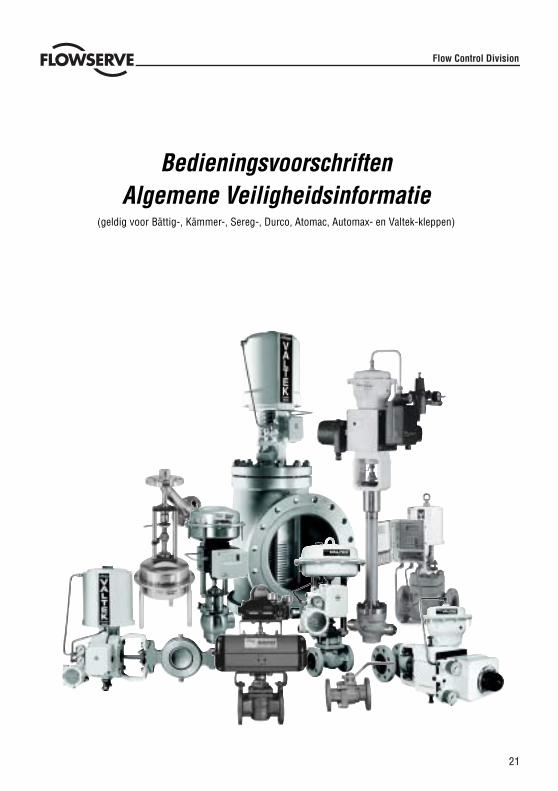
BedieningsvoorschriftenAlgemene Veiligheidsinformatie
(geldig voor Bättig-, Kämmer-, Sereg-, Durco, Atomac, Automax- en Valtek-kleppen)
Flow Control Division
22
CORRECT GEBRUIK VAN FLOWSERVE KLEPPEN EN AANDRIJVINGEN
Veiligheidsbegrippen
In deze gebruiksaanwijzing worden de veiligheidsbegrippen GEVAAR, WAARSCHUWING,VOORZICHTIG en ATTENTIE gebruikt om de nadruk te leggen op bijzondere gevaren en/of aanvullende informatiete verstrekken over aspecten die misschien niet direct duidelijk zijn.
GEVAAR: geeft aan dat er levensgevaar,ernstig persoonlijk letsel en/of aanzienlijke materiële schade zalontstaan, indien niet de juiste voorzorgsmaatregelen worden getroffen.WAARSCHUWING: geeft aan dat er levensgevaar,ernstig persoonlijk letsel en/of aanzienlijke materiëleschade kan ontstaan, indien niet de juiste voorzorgsmaatregelen worden getroffen.VOORZICHTIG: geeft aan dat er enig persoonlijk letsel en/of materiële schade kan ontstaan, indien nietde juiste voorzorgsmaatregelen worden getroffen.ATTENTIE: geeft aanvullende technische informatie, die zelfs voor gekwalificeerd personeel niet altijdgeheel duidelijk is. Het is ook belangrijk dat andere, niet extra benadrukte aanwijzingen met betrekkingtot vervoer, assemblage, bediening en onderhoud, alsmede met betrekking tot technische documentatie(b.v. in de gebruiksaanwijzing, productdocumentatie of op het product zelf) nageleefd worden teneindestoringen te vermijden, die op zich direct of indirect ernstig persoonlijk letsel of materiële schade zoudenkunnen veroorzaken.
Gebruik
De volgende instructies zijn bedoeld om te helpen bij het uitpakken, monteren en uitvoeren van noodzakelijkonderhoud aan FLOWSERVE producten. Productgebruikers en onderhoudspersoneel dienen deze handleidingnauwkeurig te bestuderen, alvorens tot installatie, ingebruikname of onderhoudswerkzaamheden over te gaan.
GEVAAR: In de meeste gevallen zijn FLOWSERVE kleppen en aandrijvingen voor specifieke toepassingenontworpen (b.v. met betrekking tot medium, druk, temperatuur). Om deze reden mogen zij niet gebruiktworden voor andere toepassingen zonder dat eerst met de fabrikant overleg heeft plaatsgevonden.
Beschermende kleding
FLOWSERVE producten worden vaak gebruikt bij moeilijke toepassingen (b.v. extreem hoge druk, gevaarlijke,giftige of agressieve media). Kleppen met balgafdichting wijzen in het bijzonder op zulke toepassingen. Zorg erbij onderhoud, inspectie of reparaties altijd voor, dat de klep en aandrijving drukloos zijn en dat de klep schoongemaaktis en vrij is van schadelijke stoffen. Besteed in zulke gevallen bijzondere aandacht aan persoonlijke bescherming(beschermende kleding, handschoenen, veiligheidsbril, etc.).
Gekwalificeerd personeel
Onder gekwalificeerd personeel worden personen verstaan die door degenen die verantwoordelijk zijn voor deveiligheid van de fabriek zijn gemachtigd het noodzakelijke werk uit te voeren, een en ander op grond van hunopleiding, ervaring en instructie en hun kennis van desbetreffende normen, specificaties, werkomstandigheden envoorschriften ter voorkoming van ongevallen; hierdoor ook kunnen zij mogelijke gevaren herkennen en vermijden.
Reserveonderdelen
Gebruik alleen originele FLOWSERVE reserveonderdelen. FLOWSERVE kan geen verantwoordelijkheid aanvaardenvoor schade, die is ontstaan door het gebruik van reserveonderdelen of bevestigingsmaterialen van een anderfabrikaat. Indien FLOWSERVE producten (in het bijzonder afdichting materialen) al langere tijd opgeslagen zijngeweest, wordt aanbevolen deze, vóór gebruik, op roestvorming of achteruitgang in kwaliteit te controleren. Deeindgebruiker moet brandveiligheidsvoorzieningen voor FLOWSERVE producten treffen.
STOP!
23
UITPAKKEN
Bij elke levering wordt een pakbon bijgevoegd. Controleer bij het uitpakken alle geleverde kleppen en toebehorenmet behulp van deze pakbon.
Grotere kleppen kunnen opgehesen worden met behulp van stroppen aan de juk of jukstangen of, indien aanwezig,aan hijsaansluitingen of hijsogen. Bij gebruik van stroppen deze zo bevestigen dat leidingen of onderdelen die aande buitenzijde zijn bevestigd, niet kunnen beschadigd kunnen raken.
WAARSCHUWING: Let er bij gebruik van stroppen op dat het zwaartepunt van de regelklep boven hethijspunt kan liggen. In zo’n geval moet u de klep vasthouden of ondersteunen, zodat deze niet kandraaien, om materiële schade of persoonlijk letsel te voorkomen.
Meld transportschade onmiddellijk aan de vervoerder.
Neem bij afwijkingen contact op met uw dichtstbijzijnde FLOWSERVE verkoopkantoor.
INSTALLATIE
GEVAAR: Controleer vóór installatie het ordernummer, serienummer en/of tag nummer, zodat u zekerweet dat u de juiste klep/aandrijving voor de bedoelde toepassing heeft ontvangen.
Isoleer geen radiatiebonnets of verlengingen voor warme of koude toepassingen.
Leidingen dienen correct uitgelijnd te zijn, zodat de klep niet onder spanning wordt gemonteerd.
INBEDRIJFSTELLING
Reinig de leidingen vóór installatie.Monteer de klep zo mogelijk in een verticale positie (aandrijving bovenaan) om het onderhoud te vergemakkelijken.Een verticale montage positie is belangrijk bij lage temperatuurtoepassingen om de afstand tussen stopbuspakkingen medium zo groot mogelijk te houden. De pakking houdt dan zoveel mogelijk de omgevingstemperatuur vast.
ATTENTIE: Isoleer geen radiatiebonnets en verlengingen voor warme of koude toepassingen.
Zorg ervoor dat er voldoende vrije ruimte boven de aandrijving blijft voor eventuele demontage van de plug uit hetklephuis.. Zie de voorschriften voor Installatie, Bediening en Onderhoud (Gebruiksaanwijzing) voor meergedetailleerde informatie.Controleer tijdens installatie de stromingsrichting opnieuw. De pijl op de klep laat de stromingsrichting zien.Indien de klep in de leiding moet worden gelast, zorg er dan voor dat de klep beschermd wordt tegen overmatigeverhitting. Het lassen dient te geschieden door gekwalificeerde lassers.
Het aansluiten van toevoerdruk en signaalleidingen
Regelkleppen worden geleverd met een klepstandsteller. De eindaansluitingen voor toevoerdruk en signaal zijnduidelijk gemarkeerd. Aandrijving en klepstandsteller zijn geschikt voor maximale toevoerdruk, zoals aangegevenop het product en in de van toepassing zijnde gebruiksaanwijzing. Indien de toevoerdruk de gespecificeerde druk teboven gaat, is een drukreduceerstation nodig. Indien er geen instrumentenlucht beschikbaar is, wordt aanbevoleneen olie- afscheider/luchtfilter in de luchtinlaatleiding te installeren, zoals omschreven in ISA norm S7.3. Alleaansluitingen moeten lekvrij zijn.
STOP!
24
SNELLE CONTROLE
De klep vóór gebruik als volgt controleren:Open en sluit de klep, en kijk naar de beweging van de aandrijving as. De beweging moet gelijkmatig zijn.Controleer de maximale slag door middel van het wijzigen van het signaal (d.w.z. pneumatisch / elektrisch signaal).Controleer alle luchtaansluitingen op lekken.Controleer of de pakkingmoer(en) goed aangedraaid zijn.Pakkingmoer(en) moeten iets strakker aangedraaid wordendan handvast. Draai echter slechts zover aan , dat stem lekkage wordt voorkomen (zie de van toepassing zijndegebruiksaanwijzing voor nadere gegevens).
ATTENTIE: Een te strak aangedraaide stopbuspakking kan leiden tot overmatige slijtage van de pakkingen kan de vrije beweging van de plugsteel belemmeren.
Controleer de veiligheidsstand. Sluit hiertoe de toevoerdruk en/of het elektrisch signaal af. Kijk of de regelklepopent of sluit zoals is voorgeschreven.Indien temperatuurwisseling plaatsvindt, draai dan alle boutverbindingen en pakkingen zo nodig opnieuw aan encontroleer op lekken.
ALGEMEEN ONDERHOUD
Om mogelijk persoonlijk letsel of productschade te vermijden, moeten veiligheidseisen en nationale regels tenaanzien van gezondheid en veiligheid streng in acht worden genomen. Het wijzigen van dit product, het vervangendoor niet originele fabrieksonderdelen of het gebruik van andere onderhoudsmethoden dan in deze instructie vermeldkunnen de werking ernstig beïnvloeden en gevaarlijk zijn voor personeel en apparatuur, en maken bestaande garantiesongeldig.
GEVAAR: Tussen aandrijving en klep bevinden zich bewegende delen. Zorg daarom, om letsel te vermijden,bij het bedienen van de klep dat handen, haar en kleding niet in de buurt komen van bewegende delen.
Het lassen bij reparaties of bij lasverbindingen mag alleen geschieden door geschoold en gekwalificeerd laspersoneel.Naast de gebruiksaanwijzing en de verplichte richtlijnen ten aanzien van het voorkomen van ongelukken die in hetland van gebruik gelden, moeten alle erkende regels ten aanzien van veiligheid en goed technisch vakmanschapworden nageleefd.
WAARSCHUWING: VOORDAT producten naar FLOWSERVE worden geretourneerd voor reparatie ofonderhoud, moet FLOWSERVE een schriftelijke verklaring ontvangen waarin staat dat het product ontsmetis en schoon is. Flowserve accepteert geen zendingen zonder zo’n schriftelijke verklaring (een formulieris te verkrijgen bij FLOWSERVE ).
Opslag
FLOWSERVE producten worden vervaardigd uit verschillende materialen. Producten die niet zijn vervaardigd uitroestwerende materialen, worden voorzien van een juiste bescherming. Daardoor zijn FLOWSERVE productengoed beschermd tegen roest.Toch moeten FLOWSERVE producten altijd deskundig opgeslagen worden in eenschone, droge omgeving.Op de flens afdichtingvlakken zitten plastic kappen om indringing van vreemde materialen te verhinderen. Dezekappen mogen pas bij de daadwerkelijke montage in het systeem verwijderd worden.
STOP!
25
Klep en aandrijving variaties
Het is niet mogelijk in deze instructies alle bijzonderheden van alle mogelijke productvariaties op te nemen. Ookkunnen deze geen specifieke informatie verstrekken voor iedere mogelijke installatie, bediening of onderhoud. Dithoudt in dat de instructies normaal alleen die aanwijzingen bevatten, die nageleefd moeten worden door gekwalificeerdpersoneel waar het product gebruikt wordt voor het doel waarvoor het bestemd is. Mocht er onzekerheid hieroverbestaan (in het bijzonder wanneer specifieke product informatie ontbreekt), dan dient men bij het juiste FLOWSERVEverkoopkantoor om uitleg te vragen.
PERIODIEK ONDERHOUD
Controleer de kleppen met regelmatige tussenpozen op juiste werking (afhankelijk van de toepassing en of ersprake is van een kritische toepassing), zoals hieronder aangegeven. Deze controle kan in de leiding uitgevoerdworden, in veel gevallen zonder onderbreking van de productie.Onderzoek pakkingen op lekken en maak zo nodig bevestigingsmiddelen opnieuw vast.Controleer de balgpakkingen en testaansluiting – indien aanwezig – op uitwendige lekken.Controleer de klep op schade, veroorzaakt door corrosieve reststoffen of corrosieve dampen.Reinig de kleppen en schilder ze zo nodig opnieuw.Controleer de pakkingdrukker op lekkage. Stel deze zo nodig bij. Zie de voorschriften voor Installatie, Bediening enOnderhoud (Gebruiksaanwijzing) voor nadere informatie.
ATTENTIE: Een te strak aangedraaide pakkingmoer kan tot overmatige slijtage van de pakking leiden enkan de vrije beweging van de plugsteel belemmeren.
Open en sluit, zo mogelijk, de klep en controleer op maximale slag en gelijkmatige beweging van de plugsteel.Onregelmatig bewegen van de plugsteel kan wijzen op inwendige gebreken.
ATTENTIE: Bij pakkingen van grafiet is onregelmatig bewegen van de plugsteel mogelijk.
GEVAAR: Houd handen, haar, kleding, enz. uit de buurt van bewegende delen. Anders bestaat er kans opernstig letsel.
Controleer of alle toebehoren stevig bevestigd zijn.Sluit zo mogelijk toevoerdruk af en controleer de veiligheidsstand.Controleer de beschermbalg op slijtage.Controleer de aandrijving op lekken. Hiertoe dient u het klephuis, luchtaansluitingen en plugsteel geleider metlekspray te sproeien. Controleer of er zich belletjes vormen.Reinig de plugsteel.Controleer, indien aanwezig, het luchtfilter en vervang zo nodig het inzetstuk.
ATTENTIE: Voor nadere informatie kunt u contact opnemen met uw dichtstbijzijnde FLOWSERVE kantoor.Gebruiksaanwijzingen zijn beschikbaar in diverse talen, o.a. Engels, Duits en Frans.

26
ESSEN
Flow Control Division
DECLARATION OF CONFORMITY
with the Pressure Equipment Directive 97/23/EC
Herewith we, the manufacturer, Flowserve Essen GmbHManderscheidtstr. 19D- 45141 EssenGermany
Declare that the construction, manufacturing and testing of the pressure equipment is in conformancewith the directive 97/23/EC.
Description of the pressure equipment:
Control valves for process control
Conformity assessment modules:
Module H: Category III, Fluid Group 1 and 2 - Certificate N° 04 202 2 043 01 04016Pressure Accessories according to Article 1, section 2.1.4
Notified body that carried out the controls and monitors the Quality-system to 97/23/EC:
RWTÜV Anlagentechnik GmbH – N°0044Kurfürstenstr. 58D – 45138 EssenGermany
Name & address of the Notified body which carried out the inspection:
Not applicable
Referenced harmonised standards used:
EN19, EN287, EN288, EN10204, EN9001, EN60534
References of other technical standards, specifications and European Directives used:
AD2000,DIN 3840
Machinery 98/37/EC,Electromagnetic Compatibility 89/336/EEC,Low voltage 72/23/EEC
Authorised Person for the Manufacturer within the European Community:
Name: Walter Friese
Title: QA-Manager
Signature: Date: 05/02/2002

27
LA CHAUX-DE-FONDS
Flow Control Division
DECLARATION OF CONFORMITY
with the Pressure Equipment Directive 97/23/EC
Herewith we, the manufacturer, Flowserve SA1, Allée du QuartzCH – 2300 La Chaux de FondsSwitzerland
Declare that the construction, manufacturing and testing of the pressure equipment is in conformancewith the directive 97/23/EC.
Description of the pressure equipment:
Control valves for process control
Conformity assessment modules:
Module H: Category III, Fluid Group 1 and 2 - Certificate N° 04 202 2 043 01 04019Pressure Accessories according to Article 1, section 2.1.4
Notified body that carried out the controls and monitors the Quality-system to 97/23/EC:
RWTÜV Anlagentechnik – N°0044Kurfürstenstr. 58D – 45138 EssenGermany
Name & address of the Notified body which carried out the inspection:
Not applicable
Referenced harmonised standards used:
EN19, EN287, EN288, EN10204, EN9001, EN10204, EN60534
References of other technical standards, specifications and European Directives used:
AD2000,DIN 3840
Machinery 98/37/EC,Electromagnetic Compatibility 89/336/EEC,Low voltage 72/23/EEC
Authorised Person for the Manufacturer within the European Community:
Name: Walter Friese
Title: QA-Manager
Signature: Date: 05/02/2002
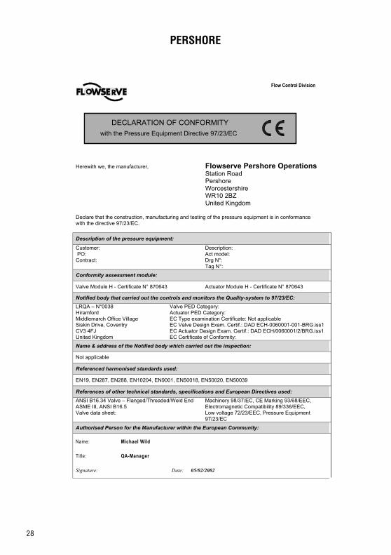
28
PERSHORE
Flow Control Division
DECLARATION OF CONFORMITY
with the Pressure Equipment Directive 97/23/EC
Herewith we, the manufacturer, Flowserve Pershore OperationsStation RoadPershoreWorcestershireWR10 2BZUnited Kingdom
Declare that the construction, manufacturing and testing of the pressure equipment is in conformancewith the directive 97/23/EC.
Description of the pressure equipment:
Customer: PO:Contract:
Description:Act model:Drg N°:Tag N°:
Conformity assessment module:
Valve Module H - Certificate N° 870643 Actuator Module H - Certificate N° 870643
Notified body that carried out the controls and monitors the Quality-system to 97/23/EC:
LRQA – N°0038HiramfordMiddlemarch Office VillageSiskin Drive, CoventryCV3 4FJUnited Kingdom
Valve PED Category:Actuator PED Category:EC Type examination Certificate: Not applicableEC Valve Design Exam. Certif.: DAD ECH-0060001-001-BRG.iss1EC Actuator Design Exam. Certif.: DAD ECH/0060001/2/BRG.iss1EC Certificate of Conformity:
Name & address of the Notified body which carried out the inspection:
Not applicable
Referenced harmonised standards used:
EN19, EN287, EN288, EN10204, EN9001, EN50018, EN50020, EN50039
References of other technical standards, specifications and European Directives used:
ANSI B16.34 Valve – Flanged/Threaded/Weld EndASME III, ANSI B16.5Valve data sheet:
Machinery 98/37/EC, CE Marking 93/68/EEC,Electromagnetic Compatibility 89/336/EEC,Low voltage 72/23/EEC, Pressure Equipment97/23/EC
Authorised Person for the Manufacturer within the European Community:
Name: Michael Wild
Title: QA-Manager
Signature: Date: 05/02/2002
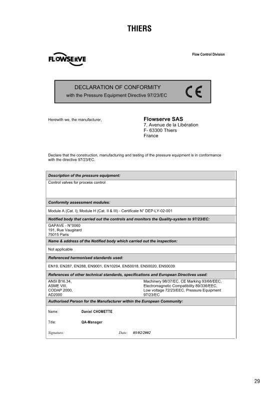
29
THIERS
Flow Control Division
DECLARATION OF CONFORMITY
with the Pressure Equipment Directive 97/23/EC
Herewith we, the manufacturer, Flowserve SAS7, Avenue de la LibérationF- 63300 ThiersFrance
Declare that the construction, manufacturing and testing of the pressure equipment is in conformancewith the directive 97/23/EC.
Description of the pressure equipment:
Control valves for process control
Conformity assessment modules:
Module A (Cat. I); Module H (Cat. II & III) - Certificate N° DEP-LY-02-001
Notified body that carried out the controls and monitors the Quality-system to 97/23/EC:
GAPAVE - N°0060191, Rue Vaugirard75015 Paris
Name & address of the Notified body which carried out the inspection:
Not applicable
Referenced harmonised standards used:
EN19, EN287, EN288, EN9001, EN10204, EN50018, EN50020, EN50039
References of other technical standards, specifications and European Directives used:
ANSI B16.34,ASME VIII,CODAP 2000,AD2000
Machinery 98/37/EC, CE Marking 93/68/EEC,Electromagnetic Compatibility 89/336/EEC,Low voltage 72/23/EEC, Pressure Equipment97/23/EC
Authorised Person for the Manufacturer within the European Community:
Name: Daniel CHOMETTE
Title: QA-Manager
Signature: Date: 05/02/2002
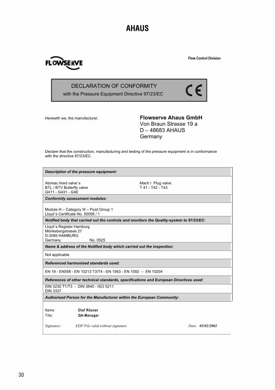
30
AHAUS
Flow Control Division
DECLARATION OF CONFORMITY
with the Pressure Equipment Directive 97/23/EC
Herewith we, the manufacturer, Flowserve Ahaus GmbHVon Braun Strasse 19 aD – 48683 AHAUSGermany
Declare that the construction, manufacturing and testing of the pressure equipment is in conformancewith the directive 97/23/EC.
Description of the pressure equipment:
Atomac lined valve`sBTL / BTV Butterfly valveG411 - G431 - G4E
Mach I Plug valveT 41 - T42 - T43
Conformity assessment modules:
Module H – Category III – Fluid Group 1Lloyd`s Certificate No. 50006 / 1
Notified body that carried out the controls and monitors the Quality-system to 97/23/EC:
Lloyd`s Register HamburgMönkebergstrasse 27D-2095 HAMBURGGermany No. 0525
Name & address of the Notified body which carried out the inspection:
Not applicable
Referenced harmonised standards used:
EN 19 - EN558 - EN 10213 T3/T4 - EN 1563 - EN 1092 – EN 10204
References of other technical standards, specifications and European Directives used:
DIN 3230 T1/T3 - DIN 3840 - ISO 5211DIN 3337
Authorised Person for the Manufacturer within the European Community:
Name: Olaf RösnerTitle: QA-Manager
Signature: EDP File valid without signature Date: 05/02/2002

31
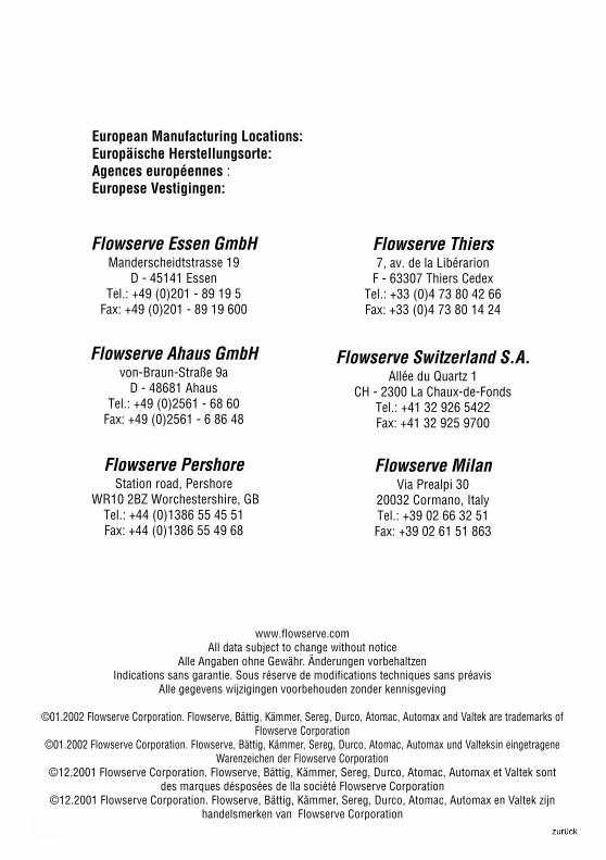
32
www.flowserve.comAll data subject to change without notice
Alle Angaben ohne Gewähr. Änderungen vorbehaltzenIndications sans garantie. Sous réserve de modifications techniques sans préavis
Alle gegevens wijzigingen voorbehouden zonder kennisgeving
©01.2002 Flowserve Corporation. Flowserve, Bättig, Kämmer, Sereg, Durco, Atomac, Automax and Valtek are trademarks ofFlowserve Corporation
©01.2002 Flowserve Corporation. Flowserve, Bättig, Kämmer, Sereg, Durco, Atomac, Automax und Valteksin eingetrageneWarenzeichen der Flowserve Corporation
©12.2001 Flowserve Corporation. Flowserve, Bättig, Kämmer, Sereg, Durco, Atomac, Automax et Valtek sontdes marques désposées de lla société Flowserve Corporation
©12.2001 Flowserve Corporation. Flowserve, Bättig, Kämmer, Sereg, Durco, Atomac, Automax en Valtek zijnhandelsmerken van Flowserve Corporation
Flowserve PershoreStation road, Pershore
WR10 2BZ Worchestershire, GBTel.: +44 (0)1386 55 45 51Fax: +44 (0)1386 55 49 68
Flowserve Switzerland S.A.Allée du Quartz 1
CH - 2300 La Chaux-de-FondsTel.: +41 32 926 5422Fax: +41 32 925 9700
Flowserve Ahaus GmbHvon-Braun-Straße 9a
D - 48681 AhausTel.: +49 (0)2561 - 68 60
Fax: +49 (0)2561 - 6 86 48
Flowserve Thiers7, av. de la Libérarion
F - 63307 Thiers CedexTel.: +33 (0)4 73 80 42 66Fax: +33 (0)4 73 80 14 24
Flowserve Essen GmbHManderscheidtstrasse 19
D - 45141 EssenTel.: +49 (0)201 - 89 19 5
Fax: +49 (0)201 - 89 19 600
European Manufacturing Locations:Europäische Herstellungsorte:Agences européennes :Europese Vestigingen:
Flowserve MilanVia Prealpi 30
20032 Cormano, ItalyTel.: +39 02 66 32 51Fax: +39 02 61 51 863
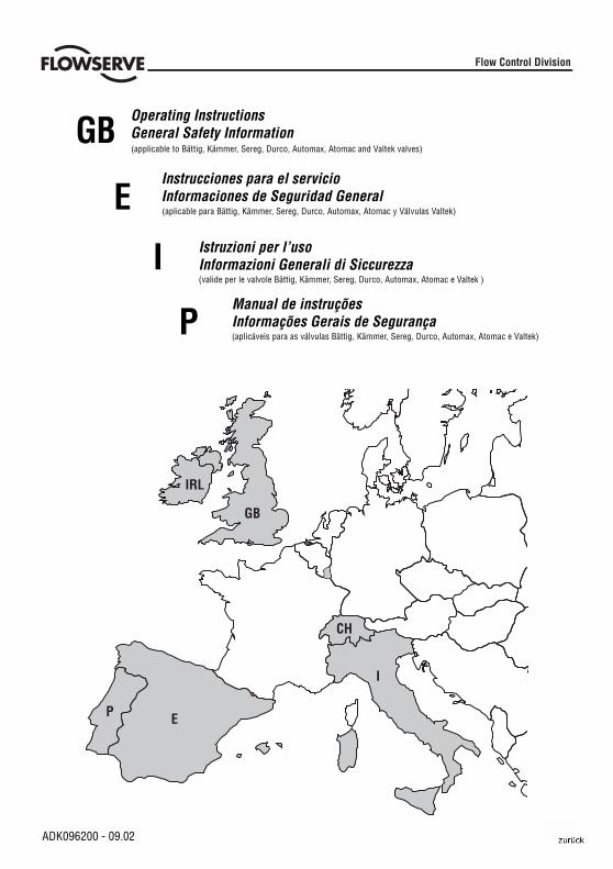
1
Instrucciones para el servicioInformaciones de Seguridad General
GB
P E
I
CH
IRL
I
Operating InstructionsGeneral Safety Information
ADK096200 - 09.02
Flow Control Division
(applicable to Bättig, Kämmer, Sereg, Durco, Automax, Atomac and Valtek valves)
Istruzioni per l’usoInformazioni Generali di Siccurezza(valide per le valvole Bättig, Kämmer, Sereg, Durco, Automax, Atomac e Valtek )
GB
E
I
P
(aplicable para Bättig, Kämmer, Sereg, Durco, Automax, Atomac y Válvulas Valtek)
Manual de instruçõesInformações Gerais de Segurança(aplicáveis para as válvulas Bättig, Kämmer, Sereg, Durco, Automax, Atomac e Valtek)
2
English ................. 3
Español ................ 9
Italiano .................. 15
Português............. 21
Declarations ......... 26
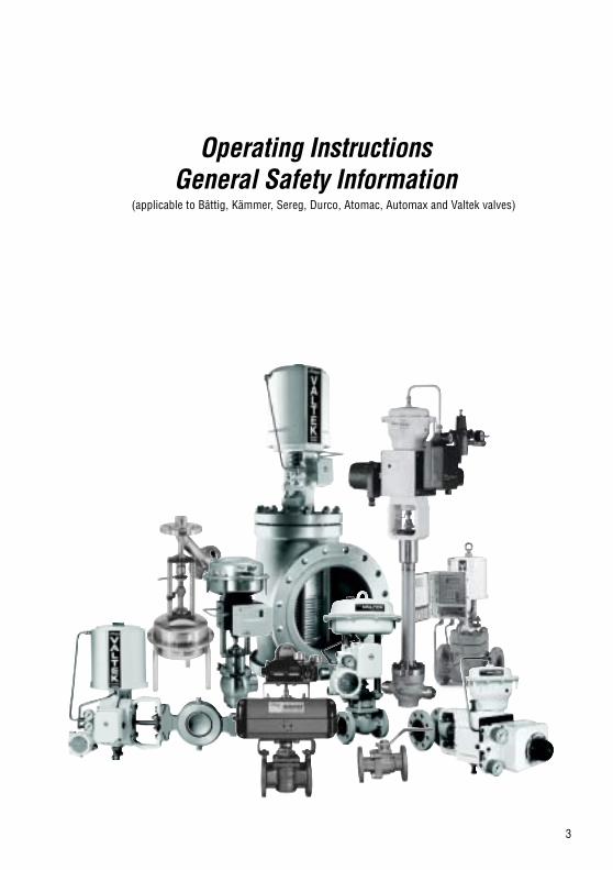
3
Operating InstructionsGeneral Safety Information
(applicable to Bättig, Kämmer, Sereg, Durco, Atomac, Automax and Valtek valves)
4
USING FLOWSERVE VALVES AND ACTUATORS CORRECTLY
Terms concerning safety
The safety terms DANGER, WARNING, CAUTION and NOTE are used in these instructions to highlight particulardangers and/or to provide additional information on aspects that may not be readily apparent.
DANGER: indicates that death, severe personal injury and/or substantial property damage will occur ifproper precautions are not taken.
WARNING: indicates that death, severe personal injury and/or substantial property damage can occur ifproper precautions are not taken.
CAUTION: indicates that minor personal injury and/or property damage can occur if proper precautionsare not taken.
NOTE: indicates and provides additional technical information, which may not be very obvious even toqualified personnel.Compliance with other, not particularly emphasised notes, with regard to transport,assembly, operation and maintenance and with regard to technical documentation (e.g. in the operatinginstruction, product documentation or on the product itself) is essential, in order to avoid faults, whichin themselves might directly or indirectly cause severe personal injury or property damage.
Using
The following instructions are designed to assist in unpacking, installing and performing maintenance as requiredon FLOWSERVE products. Product users and maintenance personnel should thoroughly review this bulletin priorto installing, operating or performing any maintenance.
DANGER: In most cases FLOWSERVE valves and actuators are designed for specific applications (e.g.with regard to medium, pressure, temperature). For this reason they should not be used in otherapplications without first consulting the manufacturer.
Protective clothing
FLOWSERVE products are often used in problematic applications (e.g. extremely high pressures, dangerous, toxicor corrosive mediums). In particular valves with bellows seals point to such applications. When performing service,inspection or repair operations always ensure, that the valve and actuator are depressurised and that the valve hasbeen cleaned and is free from harmful substances. In such cases pay particular attention to personal protection(protective clothing, gloves, glasses etc.).
Qualified personnel
Qualified personnel are people who, on account of their training, experience and instruction and their knowledge ofrelevant standards, specifications, accident prevention regulations and operating conditions, have been authorisedby those responsible for the safety of the plant to perform the necessary work and who can recognise and avoidpossible dangers.
Spare parts
Use only FLOWSERVE original spare parts. FLOWSERVE cannot accept responsibility for any damages that occurfrom using spare parts or fastening materials from other manufactures. If FLOWSERVE products (especially sealingmaterials) have been on store for longer periods check these for corrosion or deterioration before using theseproducts. Fire protection for FLOWSERVE products must be provided by the end user.
STOP!
5
UNPACKING
Each delivery includes a packing slip. When unpacking, check all delivered valves and accessories using thispacking slip.
Larger valves can be lifted using slings on the yoke or if present, using the lifting lugs or eyebolt connectionsprovided for this purpose. If slings are used, attach them so that the outer tubing or attaching parts are notdamaged.
WARNING: If slings are used, be aware that the centre of gravity of the valve may be above the liftingpoint. In this case, secure or support the valve against rotating, to prevent damage or personnel injury.
Report transport damage to the carrier immediately.
In case of discrepancies, contact your nearest FLOWSERVE sales office.
Installation
DANGER: Before installation check the order-no, serial-no. and/or the tag-no. to ensure that the valve/actuator is correct for the intended application.
Do not insulate extensions that are provided for hot or cold services.
Pipelines must be correctly aligned to ensure that the valve is not fitted under tension.
STOP!
COMMISIONING
Clean tubing prior to installing.
If possible, install the valve in an upright position (actuator on top), to ease maintenance. An upright installationposition is important with low-temperature applications, in order to keep the distance between the packing mate-rial and the medium as large as possible. The packing material then retains the ambient temperature as much aspossible.
NOTE: Do not insulate extension bonnets that are provided for hot or cold services
Make sure that sufficient overhead clearance above the actuator is maintained, to allow for disassembly of plugfrom the valve body. See Installation, Operating and Maintenance manual (IOM) for detailed information.
After installing, check direction of flow again. The direction of flow is shown by the arrow on the valve.
If the valve is to be welded into the line, make sure that the valve is shielded from excessive heat. Welding must beperformed by qualified welders.
Connecting supply pressure and signal lines.Control valves are supplied with a positioner. The end connections for supply pressure and signal are clearlymarked. Actuator and positioner are suitable for max. supply pressure as detailed on the product and within theapplicable IOM’s. If the supply pressure exceeds the pressure specified, a pressure reducing station is required. Ifinstrument air is not available, install an oil separator/air filter in the air inlet line as defined by ISA standard S7.3.All connections must be leak free.

6
STOP!
QUICK CHECK
Before operating, check the valve as follows:
Open and close the valve, and observe the movement of the actuator stem. The movement must be smooth.
Check for maximum stroke through change of signal (ie pneumatic / electrical signal).
Check all air connections for leaks.
Check packing nut(s) for proper tightness. Packing nut(s) should be slightly over finger-tight; however, tightenonly as necessary to prevent stem leakage (see appropriate IOM for details).
NOTE: An excessively tightened packing can cause excessive packing wear and can hinder the freemovement of the plug stem.
Check fail-safe position. To do this, close supply pressure and / or electrical signal and observe whether the valveopens or closes as defined.
If temperature cycling occures, re-tighten all bolt connections and packing as necessary and check for leaks.
GENERAL MAINTENANCE
To avoid possible injury to personnel or damage to products, safety rquirements and local health and safety rulesmust be strictly adhered to. Modifying this product, substituting non-factory parts, or using maintenance proceduresother than outlined in this instruction could drastically affect performance and be hazardous to personnel andequipment, and will void existing warranties.
DANGER:Between actuator and valve there are moving parts. To avoid injury keep all hands, hair andclothing away from all moving parts when operating the valve.
Welding to repair or to connect the valve may only be performed by trained and qualified welding personnel.
Apart from the operating instructions and the obligatory accident prevention directives valid in the country of use,all recognised regulations for safety and good engineering practices must be followed.
WARNING: BEFORE products are returned to FLOWSERVE for repair or service FLOWSERVE must beprovided with a certificate which confirms that the product has been decontaminated and is clean.Flowserve will not accept deliveries if a certificate has not been provided (a form can be obtained fromFLOWSERVE ).
Storage
FLOWSERVE products are manufactured from various materials. Products not manufactured from corrosion resistantmaterials are provided with an appropriate protection. This means that FLOWSERVE products are well protectedfrom corrosion. Nevertheless FLOWSERVE products must always be adequately stored in a clean, dry environment.Plastic caps are fitted to the flange faces to prevent the ingress of foreign materials. These caps should not beremoved until the valve is actually mounted into the system.
7
Valve and actuator variations
These instructions cannot claim to cover all details of all possible product variations, nor in particular can theyprovide information for every possible example of installation, operation or maintenance. This means that theinstructions normally include only the directions to be followed by qualified personnel where the product is beingused for it’s defined purpose. If there are any uncertainties in this respect particularly in the event of missingproduct-related information, clarification must be obtained via the appropriate FLOWSERVE sales office.
PERIODIC MAINTENANCE
Check valves for correct functioning at regular intervals (depending on the application and criticallity) as follows.This check can be made when installed and in many cases without interrupting production.
Examine gaskets for leaks and if necessary re-tighten fasteners.
Check bellows gasket and test connection - if present - for external leaks.
Check valve for damage caused by corrosive residues or corrosive vapours.
Clean valves and if necessary repaint.
Check glands for leakage. Adjust as necessary. See Installation, Operating and Maintenance manual (IOM) fordetailed information.
NOTE: An excessively tightened gland nut can cause excessive packing wear and can hinder the freemovement of the plug stem.
If possible, open and close valve and check for maximum stroke and smooth movement of the plug stem. Irregularmovement of the plug stem may indicate internal defects.
NOTE: With graphite packing, irregular movement of the plug stem is possible.
DANGER: Keep hands, hair, clothing, etc. away from all moving parts. Failure to do so can lead toserious injury.
Check all accessories for firm seating.
If possible, close supply pressure and check the fail-safe position.
Check stem boot for wear.
Check actuator for leaks. To do this, spray housing, air connections and plug stem guide with leak spray and checkfor any bubble formation.
Clean plug stem.
Check air filter, if present, and if necessary replace insert.
NOTE: For further information please contact your nearest FLOWSERVE location. IOM’s are available inEnglish, German, French and various other languages.

8
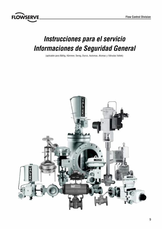
9
Flow Control Division
Instrucciones para el servicioInformaciones de Seguridad General
(aplicable para Bättig, Kämmer, Sereg, Durco, Automax, Atomac y Válvulas Valtek)
10
EL USO APROPIADO DE VÁLVULAS Y ACTUADORES FLOWSERVE
Términos que refieren a seguridad
Los términos de seguridad PELIGRO, ADVERTENCIA, CUIDADO y NOTA son empleados en estas instruccionespara resaltar peligros particulares y/o proporcionar informaciones adicionales sobre aquellos aspectos que noparezcan ser tan evidentes.
PELIGRO: Indica que ocurrirán muertes, lesiones corporales graves y/o daños materiales substancialessi no se toman las medidas de precaución adecuadas.ADVERTENCIA: Indica que pueden ocurrir muertes, lesiones corporales graves y/o daños materiales sino se toman las medidas de precaución adecuadas.CUIDADO: Indica que pueden ocurrir lesiones corporales leves y/o daños materiales si no se toman lasmedidas de precaución adecuadas.NOTA: Indica y proporciona informaciones técnicas adicionales que no siempre son muy evidentesincluso para el personal calificado. Su conformidad con otras notas, que no llamen particularmente laatención sobre el transporte, montaje, operación y mantenimiento y con la documentación técnica (esdecir, las instrucciones para el servicio, la documentación del producto o en el producto mismo) esesencia para evitar errores que, podrían causar directa o indirectamente graves lesiones corporales odaños materiales.
Uso
Las siguientes instrucciones han sido elaboradas para asistir en los trabajos de desembalaje, instalación y ejecu-ción del mantenimiento que requieren los productos FLOWSERVE. Los usuarios de productos y el personal demantenimiento deberían revisar esmeradamente este boletín antes de instalar, operar o ejecutar cualquier mante-nimiento.
PELIGRO: En la mayoría de los casos, las válvulas y los actuadores FLOWSERVE han sido diseñadospara aplicaciones específicas (por ej. con respecto al medio, la presión y a la temperatura). Por eso, nodeberían ser empleados para otras aplicaciones sin antes consultar con el fabricante.
Ropa protectora
Los productos FLOWSERVE son empleados frecuentemente en aplicaciones problemáticas (por ej. presiones ex-tremadamente altas, medios peligrosos, tóxicos o corrosivos). Las válvulas con juntas de fuelle señalan particu-larmente esas aplicaciones. Antes de ejecutar el servicio, las operaciones de inspección o reparación asegúrensesiempre que la válvula y el actuador estén despresurizados y que la válvula haya sido limpiada, y esté libre desustancias dañinas. En esos casos, ponga particular atención a la protección personal (ropa protectiva, guantes,gafas, etc.).
Personal calificado
El personal calificado está compuesto por personas que debido a la práctica, experiencia y formación que tienenasi como un conocimiento profundo de las condiciones de servicio, normas y especificaciones para la prevenciónde accidentes, ha sido autorizado por los responsables de la seguridad de la planta para ejecutar el trabajo reque-rido indentificando y evitando cualquier peligro posible.
Recambios
Utilice solamente piezas de recambio de origen FLOWSERVE. FLOWSERVE no puede asumir ninguna responsa-bilidad de cualquier daño que ocurra debido al empleo de recambios o material de fijación procedentes de otrosfabricantes. Si los productos FLOWSERVE (especialmente los materiales de obturación) han estado almacenadosdurante mucho tiempo, cabe comprobar si hay corrosión o deterioro antes de utilizar esos productos. La protec-ción contra incendios para los productos FLOWSERVE deberá ser proporcionada por el usuario final.
STOP!
11
STOP!
DESEMBALAJE
Cada entrega incluye un albarán de envío. Chequear todas las válvulas y accesorios entregados utilizando estealbarán al proceder al desembalaje,
Las válvulas de gran tamaño pueden ser alzadas empleando bucles en el arco o, si están presentes, empleando losojales de elevación o uniones por armella proporcionados para este propósito. Si se emplean bucles, tengancuidado de fijarlos de tal manera que no dañen la tubería exterior ni los componentes.
ADVERTENCIA: Al emplearse bucles, tenga en cuenta que el centro de gravedad de la válvula se encuentreencima del punto de elevación. En este caso, asegure o apoye la válvula contra la rotación, a fin deprevenir daños o lesiones corporales.
Informe al transportista inmediatamente sobre cualquier daño durante el transporte.
En el caso de discrepancias, póngase en contacto con su oficina de ventas FLOWSERVE más cercana.
INSTALACIÓN
PELIGRO: Antes de efectuar la instalación, chequee el no. de pedido, el no. de serie y/o el no. de etiquetacolgante para asegurarse de que la válvula/el actuador sea correcta(o) para la aplicación intencionada.
No aislar las extensiones suministradas para el servicio caliente o frío
Las tuberías deberán ser alineadas correctamente para asegurarse que la válvula no esté bajo tensión.
PUESTA EN SERVICIO
Limpie la tubería antes de efectuar la instalación.
Si es posible, instale la válvula en posición vertical (actuador arriba) para simplificar el mantenimiento. Unainstalación en posición vertical es importante en el caso de aplicaciones de baja temperatura, a fin de guardar ladistancia mayor posible entre la empaquetadura y el fluido. De esta manera, la empaquetadura se mantiene atemperatura ambiente lo más posible.
NOTA: No aislar las tapas de extensión suministradas para el servicio caliente o frío
Asegúrese de que haya suficiente espacio libre encima del actuador, para permitir sacar el obturador del cuerpo dela válvula. Para informaciones más detalladas, véase el manual de instalación, servicio y de mantenimiento (IOM).
Tras efectuar la instalación, chequee de nuevo la dirección de fluido. La dirección de fluido está indicada por unaflecha en la válvula.
Si la válvula debe ser soldada en línea, asegúrese de que la válvula esté protegida contra un calor excesivo. Lasoldadura deberá ser realizada por soldadores calificados.
Conexión de la presión de alimentación y señales de mando .
Las válvulas de control son suministradas con un posicionador. Las conexiones finales de la presión de alimentacióny señales están marcados claramente. El actuador y el posicionador están previstos para una presión de alimentaciónmáxima como indicado en el producto, y en el manual de instalación y mantenimiento de esa aplicación (IOM). Sila presión de alimentación excede la presión especificada, se requiere una estación reductora de presión. Si no sedisponible de ningún aire de instrumento, se debe instalar entonces un separador de aceite / filtro de aire en lalínea de entrada de aire, según el estándar ISA S7.3. Todos las conexiones deberán ser libres de fugas.
12
STOP!
CHEQUEO RÁPIDO
Antes de la puesta en marcha de cualquier la válvula, proceder de la siguiente manera:
Abrir y cerrar la válvula observando el movimiento del vástago del actuador. El movimiento deberá ser suave.
Compruebe el ciclo máximo a travès del cambio de señal (es decir, señal neumática / eléctrica).
Compruebe todas las conexiones de aire para ver si hay fugas.
Compruebe que la(s) tuerca(s) de la empaquetadura esté(n) suficientemente apretada(s). Esta(s) tuerca(s) deberá(n)ser apretada(s) a mano sin pasar nunca del punto de apriete necesario para prevenir fugas en el vástago (paradetalles, ver el manual IOM apropiado).
NOTA: Una empaquetadura excesivamente apretada puede causar un desgaste excesivo deempaquetadura y puede impedir que el vástago se mueva libremente.
Verifique la posición de seguridad en caso de fallo de aire. Para ello, cierre la presión de alimentación y/ o la señaleléctrica y observe si se abre o cierra la válvula según definido.
Si hubiesen cambios de temperatura, entonces habría que volver a apretar todos los pernos y tuercas asi como laempaquetadura según sea necesario, y comprobar que no hayan fugas.
MANTENIMIENTO GENERAL
Para prevenir posibles lesiones corporales o daños materiales, deberán observarse estrictamente las instruccionesde seguridad y la normativa local sobre salud y seguridad. La garantía quedará anulada en caso de modificacionesdel producto, sustituciones con piezas de recambio ajenas a FLOWSERVE o aplicación de procesos de mantenimientodiferentes a los que están definidos en estas instrucciones. Todo ello podría afectar radicalmente el rendimiento yresultar peligroso para el personal y el equipo,.
PELIGRO: Entre el actuador y la válvula hay partes móviles. A fin de evitar lesiones, mantenga alejadasde todas las partes móviles las manos, el pelo y la ropa al operar la válvula.
Cualquier trabajo de soldadura para reparar o conectar las válvulas deberá ser ejecutado exclusivamente por personascalificadas para ello.
Además de las instrucciones de servicio y las directivas obligatorias para la prevención de accidentes en el país deuso, deberán ser observadas todas las normas de seguridad e ingeniería reconocidas.
ADVERTENCIA: ANTES de retornar cualquier producto a FLOWSERVE para propósitos de reparación oservicio técnico, el usuario deberá proporcionar un certificado confirmando que el producto ha sidodescontaminado y limpiado. Flowserve no aceptará entregas sin haber recibido dicho certificado (unformulario puede ser obtenido de FLOWSERVE).
Almacenamiento
Los productos FLOWSERVE son fabricados en diferentes materiales. Los productos compuestos por materialesno resistentes a la corrosión llevarán un dispositivo de protección apropiado. Eso significa que los productosFLOWSERVE están bien protegidos contra la corrosión. Sin embargo, los productos FLOWSERVE siempre deberánser almacenados adecuadamente en un ambiente limpio y seco. Las caperuzas de plástico están ajustadas a lascaras de las bridas para impedir la entrada de materiales ajenos. Estas caperuzas no deberán ser retiradas hastaque la válvula sea realmente montada en el sistema.
13
Variaciones de válvula y actuador
Estas instrucciones no pretender cubrir todos los detalles de variaciones posibles de los productos ni tampocoproporcionar una información exhaustiva de todos los ejemplos posibles de instalación, servicio o mantenimiento.Lo que significa que las instrucciones normalmente sólo incluyen las directivas que debe seguir el personalcalificado en el lugar de utilización de un producto para una applicación definida. Si hay dudas en este aspecto,particularmente si se carece de información relacionada al producto, se deberá pedir clarificaciones a la oficina deventa de FLOWSERVE más cercana.
MANTENIMIENTO PERIÓDICO
Verificar el funcionamiento correcto de las válvulas en intervalos regulares (según la aplicación y el servicio más omenos crítico) de la siguiente manera: dicho control podrá ser realizado después de la instalación y, en muchoscasos, sin interrumpir la producción.
Examinar las juntas para ver si hay fugas y, en caso de necesidad, volver a apretar los tornillos de ajuste.
Examinar la junta de fuelle y comprobar la conexión – si existe – para ver si hay fugas externas.
Comprobar si la válvula está dañada debido a residuos corrosivos o vapores corrosivos
Limpar las válvulas y, en caso de necesidad, volver a pintarlas.
Comprobar la presencia de fugas a nivel de las prensaestopas. Ajustarlas en caso de necesidad.
Para informaciones detalladas, véase el manual de instalación, servicio y de mantenimiento (IOM).
NOTA: Una tuerca de empaquetadura excesivamente apretada puede causar un desgaste excesivo eimpedir el movimiento libre del vástago del obturador.
Si es posible, abrir y cerrar la válvula y observar el movimiento del vástago del obturador. Este movimento debeser suave. Un movimiento irregular del vástago puede indicar defectos internos.
NOTA: Con una empaquetadura de grafito pueden ocurrir movimientos irregulares del vástago.
PELIGRO: Mantenga las manos, el pelo, la ropa, etc fuera de alcance de las partes en movimiento.El incumplimiento de esta norma puede causar lesiones graves.
Comprobar la posición correcta de todos los accesorios.
Si es posible, cerrar la presión de alimentación y verificar la posición a fallo de aire.
Comprobar el desgaste del dispositivo protector del vástago.
Comprobar si el actuador tiene fugas. Para ello, rocíe con un espray indicador de fugas la carcasa, las conexionesde aire y la guía del vástago y comprobar si se forman burbujas.
Limpiar el vástago de obturador
Comprobar el filtro de aire si existe y, si es necesario reemplazarlo.
NOTA: Para más información, por favor póngase en contacto con la delegación de FLOWSERVE máscercana. Los manuales IOM existen en inglés, alemán, francés y en otros idiomas.

14
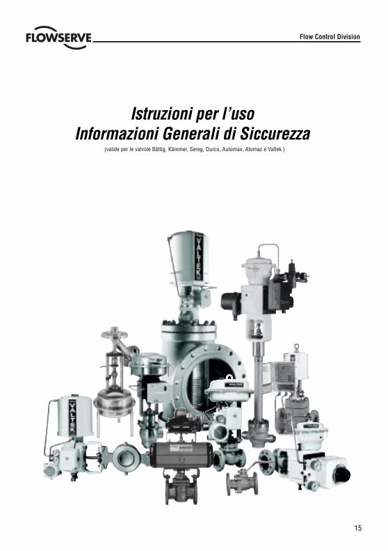
15
Istruzioni per l’usoInformazioni Generali di Siccurezza
Flow Control Division
(valide per le valvole Bättig, Kämmer, Sereg, Durco, Automax, Atomac e Valtek )
16
IMPIEGO CORRETTO DELLE VALVOLE E ATTUATORI FLOWSERVE
Termini inerenti la sicurezza
I termini indicanti PERICOLO, AVVERTENZA, ATTENZIONE, NOTA vengono usati in queste istruzioni per indicareparticolari pericoli oppure per fornire informazioni specifiche, che richiedono un contrassegno speciale.
PERICOLO: significa che la mancata osservanza di questa segnalazione causera’ pericolo di vita, gravidanni a persone e/o notevoli danni materiali.AVVERTENZA: significa che la mancata osservanza di questa segnalazione può causare pericolo di vita,gravi danni a persone e/o notevoli danni materiali.ATTENZIONE: significa che la mancata osservanza di questa segnalazione può causare il pericolo diinfortuni e/o danni materiali di minore entita’.NOTA: questa segnalazione fornisce informazioni tecniche aggiuntive, che potrebbero essere poco evidentianche per il personale specializzato. Naturalmente è importante anche osservare attentamente anche lealtre istruzioni, che non sono state particolarmente evidenziate, per il trasporto, il montaggio, l’esercizioe la manutenzione, così come i dati tecnici (nella documentazione del prodotto e sullo stesso apparecchio).L’osservanza di queste istruzioni consente di evitare errori, i quali a loro volta potrebbero causaredirettamente o indirettamente gravi danni a persone o a cose.
Impiego
Queste istruzioni rappresentano un ausilio per il disimballaggio, l’installazione e per la manutenzione cosi’ omerichiesto sui prodotti FLOWSERVE. Gli utilizzatori ed il personale addetto alla manutenzione deve leggereaccuratamente queste istruzioni, prima di eseguire i lavori di installazione, messa in funzione oppure prima dieseguire dei lavori di manutenzione.
PERICOLO: Le valvole e gli attuatori FLOWSERVE sono concepiti e costruiti per condizioni di impiegoben precise (ad esempio in funzione della portata dei fluidi, della pressione e della temperatura) e nondevono essere usati per applicazioni diverse da quelle prescritte salvo previa consultazione con ilproduttore.
Indumenti di protezione
Le valvole e gli attuatori FLOWSERVE vengono spesso usati in applicazioni problematiche (alte pressioni, mezzipericolosi, tossici oppure caustici). In particolare le valvole con guarnizioni a soffietto servono per queste applicazioni.Per i lavori di manutenzione, ispezione o riparazione bisogna fare particolare attenzione, che le valvole e gli attuatorisiano depressurizzati e che le valvole siano state sufficientemente pulite e quindi prive di residui pericolosi. Inoltrein questo contesto bisogna indossare l’ abbigliamento protettivo adeguato (indumenti, guanti, occhiali protettiviecc.).
Personale qualificato
Fanno parte del personale qualificato quelle persone che in base alla loro formazione professionale, esperienza eistruzione, alle loro conoscenze in materia di prescrizioni applicabili, regolamenti e norme antinfortunistiche econdizioni di esercizio, sono autorizzate dai responsabili della sicurezza ad eseguire i lavori necessari e nel contemposono in grado di riconoscere ed evitare possibili pericoli.
Pezzi di ricambio
Devono essere utilizzati solo pezzi di ricambio originali FLOWSERVE. Per i pezzi di ricambio oppure per il materialedi fissaggio di altri produttori la FLOWSERVE non può offrire nessuna prestazione di garanzia nel caso in cuiinsorgano eventuali danni. I prodotti FLOWSERVE, che sono stati tenuti per lungo tempo in magazzino (in particolarei componenti di tenuta), prima del montaggio devono essere controllati per eventuali danneggiamenti, corrosionioppure segni di invecchiamento.
STOP!
17
DISIMBALLAGGIO
Ogni fornitura include anche una lista dei pezzi. Durante il disimballaggio controllare tutte le valvole e gliaccessori con l’aiuto di questa lista dei pezzi forniti.
Le valvole di grandi dimensioni possono essere sollevate mediante l’applicazione di cinghie nelle aste del telaio/ occhielli oppure - se presenti - negli appositi passanti per il trasporto. Se per il disimballaggio vengonoutilizzate le cinghie per il sollevamento, queste devono essere applicate in maniera tale che la tubazione esternaoppure i componenti non vengano danneggiati.
AVVERTENZA: Se vengono usate delle cinghie di sollevamento, il baricentro della valvola può trovarsiin un punto più alto rispetto al punto di imbragatura. In questi casi bisogna impedire la rotazionedella valvola oppure bisogna supportarla, onde evitare danni a persone o a cose.
Eventuali danni dovuti al trasporto devono essere subito segnalati allo spedizioniere.
In caso di irregolarità mettersi subito in contatto con la sede FLOWSERVE più vicina.
INSTALLAZIONE / MONTAGGIO
PERICOLO: Prima del montaggio/installazione bisogna controllare esattamente il numero d’ordine,il numero di serie oppure al numero di tag per assicurarsi che la valvola sia adatta allo scopoprevisto.
Le prolunghe oppure gli inserti che servono per l’asportazione di calore oppure per il riscaldamento, nondevono essere isolati.
Le tubazioni devono essere allineate in maniera tale che la valvola possa essere montata senza tensionie. Iprovvedimenti per la protezione antincendio per i prodotti della FLOWSERVE devono essere attuati dall’esercente.
MESSA IN FUNZIONE
Prima di eseguire l’installazione è necessario pulire la tubazione. Laddove è possibile, la valvola deve essereinstallata nella posizione di montaggio verticale (attuatore sopra), per semplificare in questo modo i lavori dimanutenzione. La posizione di montaggio verticale e importante soprattutto con le applicazioni a bassatemperatura, per mantenere una distanza più grande possibile tra il materiale di tenuta e il mezzo fluido. Inquesto modo il materiale di tenuta mantiene ampiamente la temperatura ambiente.
NOTA: Le prolunghe oppure gli inserti che servono per l’asportazione di calore oppure per ilriscaldamento, non devono essere isolati.
Assicurarsi, che sopra l’attuatore vi sia una distanza sufficiente, per consentire in questo modo, durante i lavoridi manutenzione, l’estrazione della parte superiore della valvola dall’apposito corpo (vedere le corrispondentiistruzioni per il montaggio, l’uso e la manutenzione).
Dopo il montaggio verificare nuovamente la direzione del flusso. La direzione del flusso è contrassegnata sullavalvola da una freccia.
Se la valvola deve essere installata nella tubazione, bisogna fare in modo che la valvola venga protetta dalcalore eccessivo. Le saldature per il collegamento oppure le riparazioni sui nostri prodotti devono essereeseguite solo da persone qualificate per questo tipo di lavoro.
Allacciamento della pressione di alimentazione e dei conduttori di segnali (aria / mA)
Le valvole di controllo sono dotate di un posizionatore. Le connessioni per la pressione di alimentazione e ilsegnale sono contrassegnate in modo evidente. La quantità massima di pressione di alimentazione per l’attuatoree il posizionatore e’ riportata sul prodotto stesso e sul relativo libretto di uso e manutenzione.. Se l’aria dialimentazione supera il valore della pressione riportato, in questo caso è necessario un riduttore di pressione.Se non è disponibile nessuna aria per strumenti (depurata), bisognerà montare, secondo le necessità, un filtroper l’aria nella tubazione di mandata dell’aria di alimentazione. Tutti gli allacciamenti devono essere realizzatiesenti da perdite. Si raccomanda di osservare anche le istruzioni per l’uso e la manutenzione relative ai nostriattuatori I/P.
STOP!
18
STOP!
LCONTROLLO VELOCE
Prima della messa in funzione controllare la valvola come segue:
Aprire e chiudere la valvola ed osservare il movimento dell’asta di azionamento. Il movimento deve avvenire senzascosse.
Controllare l’alzata massima mediante la modifica del segnale (segnale pneumatico oppure elettrico).
Controllare la tenuta di tutti gli allacciamenti dell’aria.
Controllare il corretto serraggio del dado/i del materiale di tenuta. Il dado/i del materiale di tenuta deve/devonoessere stretti sempre un poco più della forza necessaria per svitarlo manualmente (vedere le corrispondenti istruzioniper il montaggio, l’uso e la manutenzione).
NOTA: Il materiale di tenuta stretto troppo saldamente provoca una eccessiva usura del materiale stessoe può ostacolare il libero movimento dell’asta conica.
Controllare la posizione di sicurezza. Per questo scopo, chiudere l’aria di alimentazione oppure il segnale elettricoed osservare, se la valvola apre e chiude come prescritto.
Dopo l’applicazione con valori di temperatura oscillanti, stringere tutti i collegamenti a vite e le tenute e controllarel’ermeticità
RIPARAZIONE / MANUTENZIONE GENERALI
Osservare assolutamente tutte le avvertenze e le indicazioni, onde evitare dei danni alle persone oppure alle cose.I montaggi eseguiti in maniera inadeguata, l’impiego di pezzi di ricambio di altri produttori oppure l’esecuzione dialtre operazioni di manutenzione diverse da quelle qui descritte, possono causare una riduzione del rendimento edei danni a persone o a cose con la conseguente esclusione della prestazione di garanzia.
PERICOLO: Tra l’attuatore e la valvola ci sono dei componenti in movimento. La Flowserve usa,particolarmente con i posizionatori montati, lamiere di protezione, onde evitare il pericolo di infortuni.Mantenere sempre lontane le mani, i capelli e gli indumenti da tutti i componenti in movimento.
Le saldature per il collegamento o le riparazioni sui nostri prodotti devono essere eseguite solo da persone qualificateper questo tipo di lavoro.
Oltre alle istruzioni per la manutenzione e alle normative antinfortunistiche del paese dove vengono impiegati icomponenti, devono essere osservate tutte le norme riconosciute per la sicurezza.
AVVERTENZA: Per le valvole, che devono essere spedite indietro alla Kämmer per scopi di manutenzioneoppure riparazione, è necessario prima trasmettere alla Kämmer un certificato che conferma che levalvole sono decontaminate e pulite. Se non è disponibile nessun certificato la FLOWSERVE non accettera’nessuna spedizione (richiedere presso la Flowserve i moduli prestampati).
Immagazzinaggio
Le valvole e gli attuatori FLOWSERVE sono costituiti da differenti materiali. Le valvole e gli attuatori costruiti conmateriali soggetti alla corrosione vengono provvisti di una adeguata protezione. In questo modo i prodottiFLOWSERVE sono protetti contro la corrosione. Tuttavia, i prodotti FLOWSERVE devono essere immagazzinati inmaniera adeguata, in un luogo asciutto e pulito. Il modo migliore per evitare un eventuale imbrattamento oppuredanneggiamento delle superfici delle guarnizioni flangiate è quello di non rimuovere la copertura della flangia finoal momento del montaggio.
19
Variazioni per valvole e attuatori
Queste istruzioni per l’uso, il montaggio e la manutenzione non possono contenere tutte le informazionidettagliate relative a tutte le possibili varianti di prodotto. Inoltre esse non possono prendere inconsiderazione ogni possibile caso di installazione, di esercizio oppure di manutenzione. Le istruzionicontengono fondamentalmente solo le indicazioni necessarie per l’impiego, conforme alle prescrizioni,nelle applicazioni del settore industriale da parte di personale qualificato. Nel caso in cui dovessero essercidei problemi da chiarire, particolarmente se dovessero mancare delle informazioni dettagliate specifichedel prodotto, questi problemi devono essere chiariti mediante il rappresentante responsabile dellaFLOWSERVE.
Manutenzione periodica
Controllare il perfetto funzionamento delle valvole ad intervalli regolari (almeno una volta ogni sei mesi)come descritto qui di seguito. Questo controllo può essere eseguito anche quando i componenti sonomontati ed in molti casi non è necessario interrompere la produzione.
Controllare le guarnizioni su eventuali perdite ed eventualmente stringere le viti.
Controllare la guarnizione a soffietto, il raccordo di prova e la vite per lo scarico del corpo valvola - sepresenti - sulla tenuta verso l’esterno.
Controllare la valvola per eventuali danneggiamenti dovuti a residui corrosivi oppure a vapori corrosivi.
Pulire le valvole ed eventualmente riverniciarle.
Controllare il corretto valore di serraggio del dado/i del materiale di tenuta (vedere le corrispondentiistruzioni per l’uso, il montaggio e la manutenzione).
NOTA: Il serraggio eccessivo del dado per raccordi provoca una eccessiva usura della tenuta epuò ostacolare il libero movimento dell’asta conica.
Se la valvola è dotata di un dispositivo di lubrificazione, controllare il livello del lubrificante ed eventualmenterabboccare.
Se possibile, aprire e chiudere la valvola ed osservare l’alzata massima ed il movimento (che deve essereesente da scosse) dell’asta conica. L’eventuale movimento irregolare dell’asta conica può indicare deidifetti interni.
NOTA: Con le tenute in grafite è possibile che l’asta conica si muova in maniera irregolare.
PERICOLO: Mantenere sempre lontane le mani, i capelli e gli indumenti da tutti i componenti inmovimento. La mancata osservanza di queste regole importanti può causare gravi infortuni.
Controllare la salda posizione degli accessori.
Se possibile, chiudere l’alimentazione dell’aria e controllare la posizione di sicurezza.
Controllare l’usura del soffietto.
Controllare l’ermeticità dell’attuatore. Per questo scopo, spruzzare i raccordi per l’aria e la guida dell’astaconica con un prodotto per il controllo della tenuta e controllare la formazione delle bolle.
Pulire l’asta conica.
Controllare, se presente, il filtro dell’aria ed eventualmente sostituire l’elemento filtrante.
NOTA: Per ulteriori informazioni sulla manutenzione e il mantenimento dell’efficienza,mettersi in contatto con l’ufficio di rappresentanza più vicino. Le istruzioni per l’uso sonodisponibili nelle lingue tedesco, inglese, francese e in altre lingue.

20

21
Manual de instruçõesInformações Gerais de Segurança
(aplicáveis para as válvulas Bättig, Kämmer, Sereg, Durco, Auromax, Atomac e Valtek)
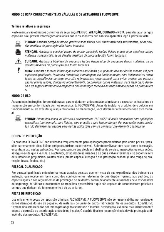
22
MODO DE USAR CORRECTAMENTE AS VÁLVULAS E OS ACTUADORES FLOWSERVE
Termos relativos à segurança
Neste manual são utilizados os termos de segurança PERIGO, ATENÇÃO, CUIDADO e NOTA, para destacar perigosespeciais e/ou prestar informações adicionais sobre os aspectos que não são aparentes logo à primeira vista.
PERIGO: Assinala perigo de morte, graves lesões físicas e/ou danos materiais substanciais, se as devi-das medidas de precaução não forem tomadas.
ATENÇÃO: Assinala o possível perigo de morte, possíveis lesões físicas graves e/ou possíveis danosmateriais substanciais, se as devidas medidas de precaução não forem tomadas.
CUIDADO: Assinala a hipótese de pequenas lesões físicas e/ou de pequenos danos materiais, se asdevidas medidas de precaução não forem tomadas.
NOTA: Assinala e fornece informações técnicas adicionais que poderão não ser óbvias mesmo até parao pessoal qualificado. Durante o transporte, a montagem, e o funcionamento, será indispensável tomartodas as providências de segurança não referenciadas neste manual, para evitar avarias que possamcausar graves lesões, directa ou indirectamente, ou provocar danos materiais. Para além disso dever-se-á de seguir estritamente a respectiva documentação técnica e os dados mencionados no produto emsi.
MODO DE USO
As seguintes instruções, foram elaboradas para o ajudarem a desembalar, a instalar e a executar os trabalhos demanutenção em conformidade com os requisitos da FLOWSERVE. Antes de instalar o produto, de o colocar emfuncionamento ou de executar quaisquer trabalhos de manutenção, você deverá ler atentamente todo este manu-al.
PERIGO: Em muitos casos, as válvulas e os actuadores FLOWSERVE estão concebidos para aplicaçõesespecíficas (por exemplo: para fluídos, para pressão e para temperaturas). Por esta razão, estes produ-tos não deveriam ser usados para outras aplicações sem se consultar previamente o fabricante.
ROUPA DE PROTECÇÃO
Os produtos FLOWSERVE são utilizados frequentemente para aplicações problemáticas (tais como por ex.: pres-sões extremamente altas, fluídos perigosos, tóxicos ou corrosivos). Sobretudo válvulas com baixo ponto de vedação,encontram uso nestas aplicações. Por isso, sempre que efectuar trabalhos de serviço, inspecções ou reparações,assegure-se de que a válvula, e o actuador, estão despressurizados e de que a válvula foi limpa e se encontra livrede substâncias prejudiciais. Nestes casos, preste especial atenção à sua protecção pessoal (e use roupa de pro-tecção, luvas, óculos, etc.)
PESSOAL QUALIFICADO
Por pessoal qualificado entendem-se todas aquelas pessoas que, em vista da sua experiência, dos treinos e dainstrução que receberam, bem como dos conhecimentos relevantes de que dispõem quanto aos padrões, àsespecificações e aos regulamentos da prevenção de acidentes, foram devidamente autorizadas pelo responsávelda segurança da fábrica a executarem os trabalhos necessários e que são capazes de reconhecerem possíveisperigos que derivam do funcionamento e de os evitarem.
PEÇAS DE REPOSIÇÃO
Use unicamente peças de reposição originais FLOWSERVE. A FLOWSERVE não se responsabiliza por quaisquerdanos derivados do uso de peças ou de materiais de união de outros fabricantes. Se os produtos FLOWSERVEtiverem sido armazenados por tempo prolongado (sobretudo o material de vedação), examine-os cuidadosamentequanto a corrosão ou deterioração antes de os instalar. O usuário final é o responsável pela devida protecção anti-incêndio dos produtos FLOWSERVE.
STOP!
23
STOP!
DESEMBALAGEM
Cada fornecimento contém uma nota de entrega. Confira todas as válvulas e acessórios com esta nota de entregalogo ao desembalar.
As válvulas mais pesadas podem ser levantadas com cordas fixadas ao respectivo lugar de encaixe ou então pelastalas ou pelos olhais das cavilhas, caso existam. Usando cordas, aperte-as de maneira a não danificar nem atubagem externa nem as partes de união.
ATENÇÃO: Usando cordas, observe que o centro de gravidade da válvula deve estar acima do ponto deelevação. Neste caso, prenda ou segure a válvula para ela não girar e evitar assim danos materiais oulesões físicas.
No caso de danos de transporte, comunique-os imediatamente à transportadora.
No caso de discrepâncias, contacte o escritório de vendas da FLOWSERVE mais próximo.
INSTALAÇÃO
PERIGO: Antes de começar com a instalação, certifique-se de que a válvula/actuador é correcta(o) paraa aplicação desejada e confira primeiro o nº da encomenda e o nº de série com os dados indicados naplaca de características da(o) válvula/actuador.
Não isole as extensões que estão previstas para serviços quentes ou frios.
As tubagens terão que estar devidamente alinhadas para que as válvulas possam ser montadas sem tensões.
COLOCAÇÃO EM FUNCIONAMENTO
Limpe os tubos antes de iniciar a montagem.
Sempre que possível, instale a válvula em posição vertical (actuador no topo) para facilitar a manutenção. Emaplicações de baixas temperaturas, a instalação vertical é importante para garantir a maior distância possível entrea guarnição de empanque e o fluído. Neste caso, o material de vedação conserva a temperatura ambiental, o maispossível.
NOTA: Não isole as emendas que estão previstas para serviços quentes ou frios.
Deixe espaço livre suficiente, acima do actuador para poder desmontar mais facilmente a chapeleta do corpo daválvula. Para mais detalhes, consulte o Manual de Instalação, Funcionamento e Manutenção (IOM).
Depois de concluir a instalação, volte a verificar o sentido do fluxo. Este sentido é indicado pela seta que seencontra no corpo da válvula.
Pretendendo soldar a válvula a um tubo, proteja-a contra calor excessivo e observe que a soldagem somentedeverá ser efectuada por soldadores profissionais.
Conexão da alimentação de pressão e das linhas de sinal.
As válvulas de comando são fornecidas com um posicionador. Os extremos para conexão da alimentação depressão e do sinal estão nitidamente marcadas. Tanto o actuador como o posicionador foram concebidos parasuportarem a pressão máxima indicada na válvula e de acordo com o respectivo Manual de Instruções, Funciona-mento e Manutenção. Se a pressão de alimentação exceder a indicada, haverá que instalar um redutor de pressão.Não havendo um instrumento de ar, instale um separador de óleo/filtro de ar no tubo de entrada do ar, segundo opadrão S7.3 ISA. As uniões terão que ficar todas hermeticamente vedadas.
24
TESTE RÁPIDO
Antes de colocar a válvula em funcionamento, verifique o seguinte:
Abra a válvula e volte a fechá-la, e observe o movimento da haste do actuador. O movimento terá que ser suave.
Verifique o curso máximo mudando de sinal (por ex.: pneumático/eléctrico).
Verifique se há quaisquer fugas nas uniões.
Verifique se os parafusos da vedação estão bem apertados. Os parafusos da vedação deveriam estar ligeiramentemais apertados do que se fossem apertados com os dedos; contudo aperte-os só o que for necessário para evitarfugas na haste (para mais detalhes, consulte o respectivo Manual de Instalação, Funcionamento e Operação).
NOTA: Uma vedação demasiado apertada pode provocar o desgaste excessivo da mesma e impedir/afectar o livre movimento da haste de conexão.
Verifique a posição do sistema de segurança integrado. Para isto, feche a alimentação da pressão e/ou o sinaleléctrico e observe se a válvula abre e fecha devidamente.
No caso de variações de temperatura, reaperte adequadamente todos os parafusos e a vedação e verifique se háalguma fuga.
MANUTENÇÃO GERAL
Para evitar possíveis acidentes pessoais e danos materiais, haverá que seguir-se rigorosamente os requisitos desegurança e observar os regulamentos de segurança e de saúde vigentes no local de montagem. A modificação doproduto, a substituição de peças por não-originais e a execução de trabalhos de manutenção que não estejam emconformidade com os descritos neste manual, podem afectar drasticamente o bom funcionamento da válvula erepresentarem uma fonte de perigo para o pessoal e para o equipamento, além de levarem à perda da garantia.
PERIGO: Entre o actuador e válvula há partes moventes. Por isso mantenha as mãos, o cabelo e ovestuário sempre afastado deles para evitar acidentes quando estiverem em funcionamento.
Os trabalhos de soldagem, para conectar ou reparar a válvula, só poderão ser efectuados por pessoal devidamentequalificado e treinado.
Para além da obrigação de observação das instruções de segurança e das directivas para a prevenção de acidentesvigentes no país de montagem, haverá que seguir-se todos os regulamentos reconhecidos para o bom funciona-mento e a segurança.
ATENÇÃO: ANTES dos produtos serem devolvidos à FLOWSERVE para reparação ou assistência, haveráque enviar um certificado, confirmado que os produtos foram descontaminados e que se encontram emestado limpo. Sem este certificado, a Flowserve não aceitará a remessa (o respectivo formulário podeser obtido na FLOWSERVE).
ARMAZENAGEM
Os produtos FLOWSERVE são fabricados de vários materiais. Aqueles produtos que não são fabricados de mate-riais resistentes à corrosão, são construídos com uma protecção apropriada. Isto significa que todos os produtosFLOWSERVE estão devidamente protegidos contra a corrosão. Contudo, estes produtos FLOWSERVE deverão sersempre devidamente armazenados em lugar limpo e seco. Os flanges estão tapados com tampas de plástico paraevitar a entrada de matérias estranhas. Estas tampas somente deverão ser removidas no acto da montagem daválvula no sistema.
STOP!
25
Variedade de válvulas e de actuadores
Este manual de montagem, de funcionamento e de manutenção, não contém os detalhes de toda a variedade deconstrução, nem considera todas as possibilidades imagináveis de montagem, de funcionamento e de manuten-ção. Por esta razão, este manual contém unicamente aquelas instruções consideradas substanciais para o usodevido, por pessoal qualificado, em sectores da indústria. No caso de dúvidas e sobretudo no caso da falta deinformações específicas do produto, queira contactar o representante da FLOWSERVE competente para a suaárea.
Manutenção
Verifique em períodos regulares (dependendo do tipo da aplicação e da perigosidade) o funcionamento correctoda válvula, procedendo como se descreve a seguir. Em muitos casos, esta verificação pode ser levada a cabo coma válvula montada e a produção em curso.
Verifique se há fugas nas juntas e reaperte os parafusos eventualmente.
Verifique a estanqueidade exterior da junta de fole e a conexão para teste, se esta existir.
Verifique a válvula quanto a danificação derivada de resíduos corrosivos ou de vapores corrosivos.
Limpe as válvulas e sendo necessário volte a pintá-las.
Verifique se há fugas no empanque e afine-o sendo necessário.
NOTA: Uma porca de capa demasiado apertada leva a desgaste excessivo do empanque e pode impediro movimento livre do veio.
Sendo possível, abra e feche a válvula. Certifique-se de que o veio se movimenta sem solavancos e observe ocurso máximo. O movimento irregular do veio pode ser o indício de um defeito interno.
NOTA: Com empanques de grafita, é possível que o veio se mova irregularmente.
PERIGO: Mantenha as mãos, o cabelo, a roupa, etc., afastados das partes moventes. A desobservaçãodesta advertência poderá levar a graves ferimentos.
Verifique o assento correcto de todos os acessórios.
Sendo possível, feche a adução do ar e verifique a posição de segurança.
Verifique se há desgaste no veio.
Verifique a estanqueidade do actuador pulverizando agente liquido próprio para verificação da mesma, no corpo,nas conexões do ar e na condução do veio e observe se há formação de bolhas.
Limpe o veio.
Verifique o filtro de ar – se este existir – e substitua o elemento eventualmente.
NOTAS: Para mais detalhes sobre a manutenção e a conservação, queira contactar o distribuidor maispróximo de si. IOM’s estão disponíveis em inglês, alemão, francês e em várias outras línguas.
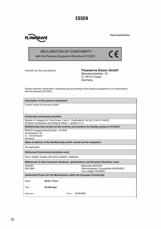
26
ESSEN
Flow Control Division
DECLARATION OF CONFORMITY
with the Pressure Equipment Directive 97/23/EC
Herewith we, the manufacturer, Flowserve Essen GmbHManderscheidtstr. 19D- 45141 EssenGermany
Declare that the construction, manufacturing and testing of the pressure equipment is in conformancewith the directive 97/23/EC.
Description of the pressure equipment:
Control valves for process control
Conformity assessment modules:
Module H: Category III, Fluid Group 1 and 2 - Certificate N° 04 202 2 043 01 04016Pressure Accessories according to Article 1, section 2.1.4
Notified body that carried out the controls and monitors the Quality-system to 97/23/EC:
RWTÜV Anlagentechnik GmbH – N°0044Kurfürstenstr. 58D – 45138 EssenGermany
Name & address of the Notified body which carried out the inspection:
Not applicable
Referenced harmonised standards used:
EN19, EN287, EN288, EN10204, EN9001, EN60534
References of other technical standards, specifications and European Directives used:
AD2000,DIN 3840
Machinery 98/37/EC,Electromagnetic Compatibility 89/336/EEC,Low voltage 72/23/EEC
Authorised Person for the Manufacturer within the European Community:
Name: Walter Friese
Title: QA-Manager
Signature: Date: 05/02/2002
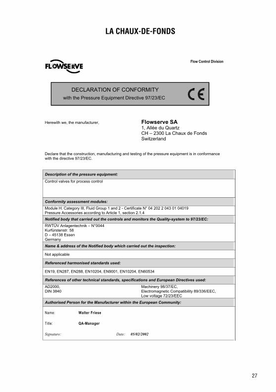
27
LA CHAUX-DE-FONDS
Flow Control Division
DECLARATION OF CONFORMITY
with the Pressure Equipment Directive 97/23/EC
Herewith we, the manufacturer, Flowserve SA1, Allée du QuartzCH – 2300 La Chaux de FondsSwitzerland
Declare that the construction, manufacturing and testing of the pressure equipment is in conformancewith the directive 97/23/EC.
Description of the pressure equipment:
Control valves for process control
Conformity assessment modules:
Module H: Category III, Fluid Group 1 and 2 - Certificate N° 04 202 2 043 01 04019Pressure Accessories according to Article 1, section 2.1.4
Notified body that carried out the controls and monitors the Quality-system to 97/23/EC:
RWTÜV Anlagentechnik – N°0044Kurfürstenstr. 58D – 45138 EssenGermany
Name & address of the Notified body which carried out the inspection:
Not applicable
Referenced harmonised standards used:
EN19, EN287, EN288, EN10204, EN9001, EN10204, EN60534
References of other technical standards, specifications and European Directives used:
AD2000,DIN 3840
Machinery 98/37/EC,Electromagnetic Compatibility 89/336/EEC,Low voltage 72/23/EEC
Authorised Person for the Manufacturer within the European Community:
Name: Walter Friese
Title: QA-Manager
Signature: Date: 05/02/2002
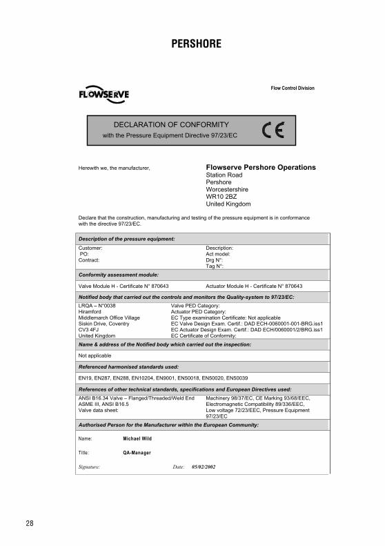
28
PERSHORE
Flow Control Division
DECLARATION OF CONFORMITY
with the Pressure Equipment Directive 97/23/EC
Herewith we, the manufacturer, Flowserve Pershore OperationsStation RoadPershoreWorcestershireWR10 2BZUnited Kingdom
Declare that the construction, manufacturing and testing of the pressure equipment is in conformancewith the directive 97/23/EC.
Description of the pressure equipment:
Customer: PO:Contract:
Description:Act model:Drg N°:Tag N°:
Conformity assessment module:
Valve Module H - Certificate N° 870643 Actuator Module H - Certificate N° 870643
Notified body that carried out the controls and monitors the Quality-system to 97/23/EC:
LRQA – N°0038HiramfordMiddlemarch Office VillageSiskin Drive, CoventryCV3 4FJUnited Kingdom
Valve PED Category:Actuator PED Category:EC Type examination Certificate: Not applicableEC Valve Design Exam. Certif.: DAD ECH-0060001-001-BRG.iss1EC Actuator Design Exam. Certif.: DAD ECH/0060001/2/BRG.iss1EC Certificate of Conformity:
Name & address of the Notified body which carried out the inspection:
Not applicable
Referenced harmonised standards used:
EN19, EN287, EN288, EN10204, EN9001, EN50018, EN50020, EN50039
References of other technical standards, specifications and European Directives used:
ANSI B16.34 Valve – Flanged/Threaded/Weld EndASME III, ANSI B16.5Valve data sheet:
Machinery 98/37/EC, CE Marking 93/68/EEC,Electromagnetic Compatibility 89/336/EEC,Low voltage 72/23/EEC, Pressure Equipment97/23/EC
Authorised Person for the Manufacturer within the European Community:
Name: Michael Wild
Title: QA-Manager
Signature: Date: 05/02/2002
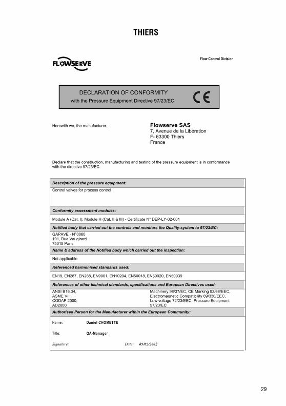
29
THIERS
Flow Control Division
DECLARATION OF CONFORMITY
with the Pressure Equipment Directive 97/23/EC
Herewith we, the manufacturer, Flowserve SAS7, Avenue de la LibérationF- 63300 ThiersFrance
Declare that the construction, manufacturing and testing of the pressure equipment is in conformancewith the directive 97/23/EC.
Description of the pressure equipment:
Control valves for process control
Conformity assessment modules:
Module A (Cat. I); Module H (Cat. II & III) - Certificate N° DEP-LY-02-001
Notified body that carried out the controls and monitors the Quality-system to 97/23/EC:
GAPAVE - N°0060191, Rue Vaugirard75015 Paris
Name & address of the Notified body which carried out the inspection:
Not applicable
Referenced harmonised standards used:
EN19, EN287, EN288, EN9001, EN10204, EN50018, EN50020, EN50039
References of other technical standards, specifications and European Directives used:
ANSI B16.34,ASME VIII,CODAP 2000,AD2000
Machinery 98/37/EC, CE Marking 93/68/EEC,Electromagnetic Compatibility 89/336/EEC,Low voltage 72/23/EEC, Pressure Equipment97/23/EC
Authorised Person for the Manufacturer within the European Community:
Name: Daniel CHOMETTE
Title: QA-Manager
Signature: Date: 05/02/2002
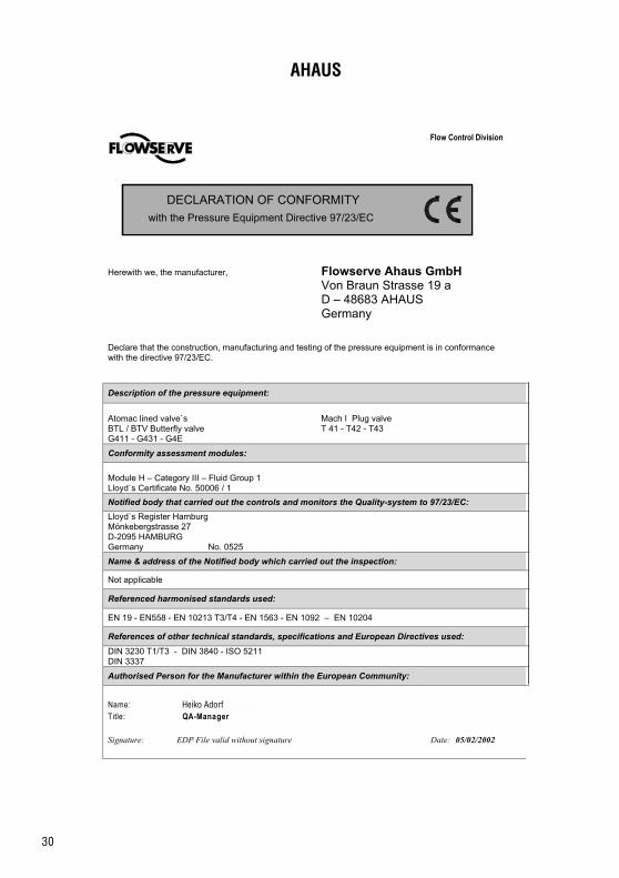
30
AHAUS
Flow Control Division
DECLARATION OF CONFORMITY
with the Pressure Equipment Directive 97/23/EC
Herewith we, the manufacturer, Flowserve Ahaus GmbHVon Braun Strasse 19 aD – 48683 AHAUSGermany
Declare that the construction, manufacturing and testing of the pressure equipment is in conformancewith the directive 97/23/EC.
Description of the pressure equipment:
Atomac lined valve`sBTL / BTV Butterfly valveG411 - G431 - G4E
Mach I Plug valveT 41 - T42 - T43
Conformity assessment modules:
Module H – Category III – Fluid Group 1Lloyd`s Certificate No. 50006 / 1
Notified body that carried out the controls and monitors the Quality-system to 97/23/EC:
Lloyd`s Register HamburgMönkebergstrasse 27D-2095 HAMBURGGermany No. 0525
Name & address of the Notified body which carried out the inspection:
Not applicable
Referenced harmonised standards used:
EN 19 - EN558 - EN 10213 T3/T4 - EN 1563 - EN 1092 – EN 10204
References of other technical standards, specifications and European Directives used:
DIN 3230 T1/T3 - DIN 3840 - ISO 5211DIN 3337
Authorised Person for the Manufacturer within the European Community:
Name:Title: QA-Manager
Signature: EDP File valid without signature Date: 05/02/2002
Heiko Adorf

31
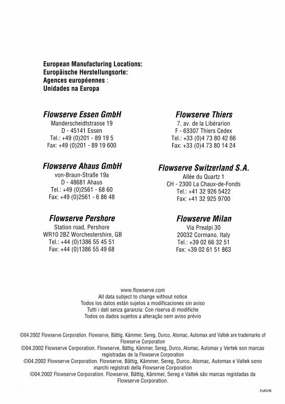
32
www.flowserve.comAll data subject to change without notice
Todos los datos están sujetos a modificaciones sin avisoTutti i dati senza garanzia: Con riserva di modifiche
Todos os dados sujeitos a alteração sem aviso prévio
©04.2002 Flowserve Corporation. Flowserve, Bättig, Kämmer, Sereg, Durco, Atomac, Automax and Valtek are trademarks ofFlowserve Corporation
©04.2002 Flowserve Corporation. Flowserve, Bättig, Kämmer, Sereg, Durco, Atomac, Automax y Vertek son marcasregistradas de la Flowserve Corporation
©04.2002 Flowserve Corporation. Flowserve, Bättig, Kämmer, Sereg, Durco, Atomac, Automax e Valtek sonomarchi registrati della Flowserve Corporation
©04.2002 Flowserve Corporation. Flowserve, Bättig, Kämmer, Sereg e Valtek são marcas registadas daFlowserve Corporation.
Flowserve PershoreStation road, Pershore
WR10 2BZ Worchestershire, GBTel.: +44 (0)1386 55 45 51Fax: +44 (0)1386 55 49 68
Flowserve Switzerland S.A.Allée du Quartz 1
CH - 2300 La Chaux-de-FondsTel.: +41 32 926 5422Fax: +41 32 925 9700
Flowserve Ahaus GmbHvon-Braun-Straße 19a
D - 48681 AhausTel.: +49 (0)2561 - 68 60
Fax: +49 (0)2561 - 6 86 48
Flowserve Thiers7, av. de la Libérarion
F - 63307 Thiers CedexTel.: +33 (0)4 73 80 42 66Fax: +33 (0)4 73 80 14 24
Flowserve Essen GmbHManderscheidtstrasse 19
D - 45141 EssenTel.: +49 (0)201 - 89 19 5
Fax: +49 (0)201 - 89 19 600
European Manufacturing Locations:Europäische Herstellungsorte:Agences européennes :Unidades na Europa
Flowserve MilanVia Prealpi 30
20032 Cormano, ItalyTel.: +39 02 66 32 51Fax: +39 02 61 51 863
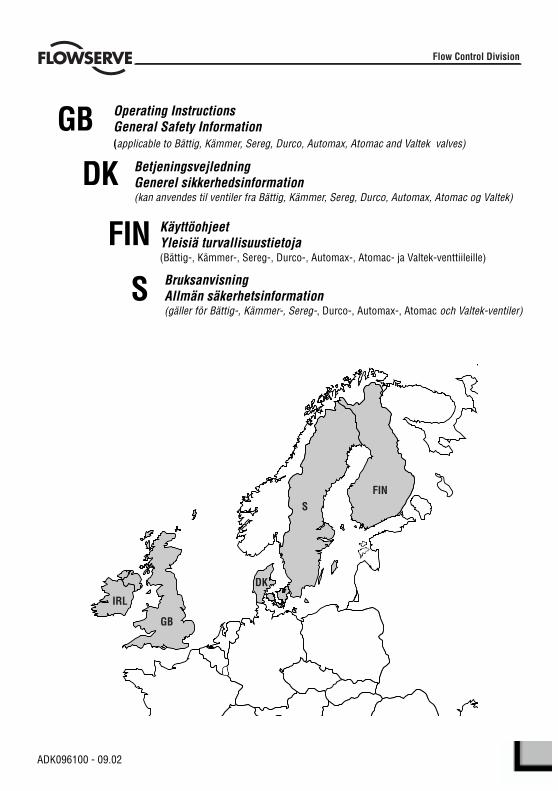
1
Flow Control Division
FINS
DK
GB
IRL
GB Operating InstructionsGeneral Safety Information(applicable to Bättig, Kämmer, Sereg, Durco, Automax, Atomac and Valtek valves)
DK BetjeningsvejledningGenerel sikkerhedsinformation(kan anvendes til ventiler fra Bättig, Kämmer, Sereg, Durco, Automax, Atomac og Valtek)
FIN KäyttöohjeetYleisiä turvallisuustietoja(Bättig-, Kämmer-, Sereg-, Durco-, Automax-, Atomac- ja Valtek-venttiileille)
S BruksanvisningAllmän säkerhetsinformation(gäller för Bättig-, Kämmer-, Sereg-, Durco-, Automax-, Atomac och Valtek-ventiler)
ADK096100 - 09.02
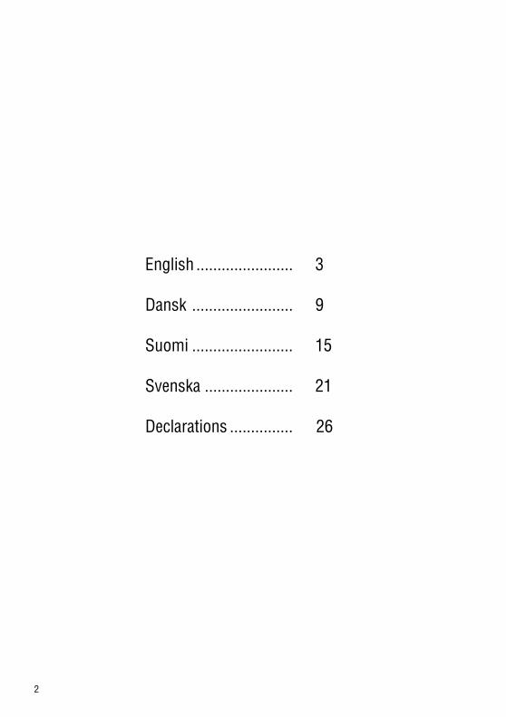
2
English ....................... 3
Dansk ........................ 9
Suomi ........................ 15
Svenska ..................... 21
Declarations ............... 26
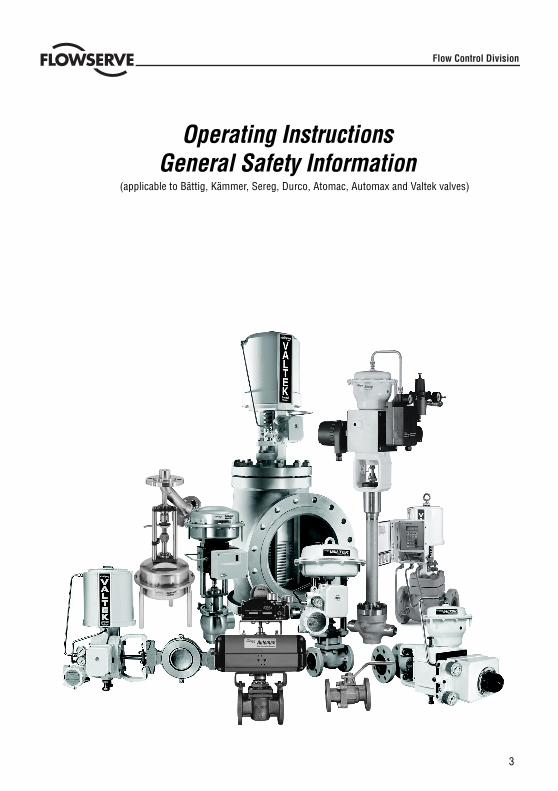
3
Operating InstructionsGeneral Safety Information
(applicable to Bättig, Kämmer, Sereg, Durco, Atomac, Automax and Valtek valves)
Flow Control Division
4
USING FLOWSERVE VALVES AND ACTUATORS CORRECTLY
Terms concerning safety
The safety terms DANGER, WARNING, CAUTION and NOTE are used in these instructions to highlight particulardangers and/or to provide additional information on aspects that may not be readily apparent.
DANGER: indicates that death, severe personal injury and/or substantial property damage will occurif proper precautions are not taken.
WARNING: indicates that death, severe personal injury and/or substantial property damage canoccur if proper precautions are not taken.
CAUTION: indicates that minor personal injury and/or property damage can occur if proper precautionsare not taken.
NOTE: indicates and provides additional technical information, which may not be very obvious evento qualified personnel.Compliance with other, not particularly emphasised notes, with regard totransport, assembly, operation and maintenance and with regard to technical documentation (e.g.in the operating instruction, product documentation or on the product itself) is essential, in order toavoid faults, which in themselves might directly or indirectly cause severe personal injury or propertydamage.
Using
The following instructions are designed to assist in unpacking, installing and performing maintenance asrequired on FLOWSERVE products. Product users and maintenance personnel should thoroughly review thisbulletin prior to installing, operating or performing any maintenance.
DANGER: In most cases FLOWSERVE valves and actuators are designed for specific applications(e.g. with regard to medium, pressure, temperature). For this reason they should not be used inother applications without first consulting the manufacturer.
Protective clothing
FLOWSERVE products are often used in problematic applications (e.g. extremely high pressures, dangerous,toxic or corrosive mediums). In particular valves with bellows seals point to such applications. When performingservice, inspection or repair operations always ensure, that the valve and actuator are depressurised and thatthe valve has been cleaned and is free from harmful substances. In such cases pay particular attention topersonal protection (protective clothing, gloves, glasses etc.).
Qualified personnel
Qualified personnel are people who, on account of their training, experience and instruction and their knowledgeof relevant standards, specifications, accident prevention regulations and operating conditions, have beenauthorised by those responsible for the safety of the plant to perform the necessary work and who can recogniseand avoid possible dangers.
Spare parts
Use only FLOWSERVE original spare parts. FLOWSERVE cannot accept responsibility for any damages thatoccur from using spare parts or fastening materials from other manufactures. If FLOWSERVE products(especially sealing materials) have been on store for longer periods check these for corrosion or deteriorationbefore using these products. Fire protection for FLOWSERVE products must be provided by the end user.
STOP!

5
UNPACKING
Each delivery includes a packing slip. When unpacking, check all delivered valves and accessories using thispacking slip.
Larger valves can be lifted using slings on the yoke or if present, using the lifting lugs or eyebolt connectionsprovided for this purpose. If slings are used, attach them so that the outer tubing or attaching parts are notdamaged.
WARNING: If slings are used, be aware that the centre of gravity of the valve may be above the liftingpoint. In this case, secure or support the valve against rotating, to prevent damage or personnelinjury.
Report transport damage to the carrier immediately.
In case of discrepancies, contact your nearest FLOWSERVE sales office.
INSTALLATION
DANGER: Before installation check the order-no, serial-no. and/or the tag-no. to ensure that thevalve/actuator is correct for the intended application.
Do not insulate extensions that are provided for hot or cold services.
Pipelines must be correctly aligned to ensure that the valve is not fitted under tension.
STOP!
COMMISIONING
Clean tubing prior to installing.
If possible, install the valve in an upright position (actuator on top), to ease maintenance. An upright installa-tion position is important with low-temperature applications, in order to keep the distance between the packingmaterial and the medium as large as possible. The packing material then retains the ambient temperature asmuch as possible.
NOTE: Do not insulate extension bonnets that are provided for hot or cold services
Make sure that sufficient overhead clearance above the actuator is maintained, to allow for disassembly ofplug from the valve body. See Installation, Operating and Maintenance manual (IOM) for detailed information.
After installing, check direction of flow again. The direction of flow is shown by the arrow on the valve.
If the valve is to be welded into the line, make sure that the valve is shielded from excessive heat. Welding mustbe performed by qualified welders.
Connecting supply pressure and signal lines.Control valves are supplied with a positioner. The end connections for supply pressure and signal are clearlymarked. Actuator and positioner are suitable for max. supply pressure as detailed on the product and withinthe applicable IOM’s. If the supply pressure exceeds the pressure specified, a pressure reducing station isrequired. If instrument air is not available, install an oil separator/air filter in the air inlet line as defined by ISAstandard S7.3. All connections must be leak free.
6
STOP!
QUICK CHECK
Before operating, check the valve as follows:
Open and close the valve, and observe the movement of the actuator stem. The movement must be smooth.
Check for maximum stroke through change of signal (ie pneumatic / electrical signal).
Check all air connections for leaks.
Check packing nut(s) for proper tightness. Packing nut(s) should be slightly over finger-tight; however, tightenonly as necessary to prevent stem leakage (see appropriate IOM for details).
NOTE: An excessively tightened packing can cause excessive packing wear and can hinder the freemovement of the plug stem.
Check fail-safe position. To do this, close supply pressure and / or electrical signal and observe whether the valveopens or closes as defined.
If temperature cycling occures, re-tighten all bolt connections and packing as necessary and check for leaks.
GENERAL MAINTENANCE
To avoid possible injury to personnel or damage to products, safety rquirements and local health and safety rulesmust be strictly adhered to. Modifying this product, substituting non-factory parts, or using maintenance proceduresother than outlined in this instruction could drastically affect performance and be hazardous to personnel andequipment, and will void existing warranties.
DANGER:Between actuator and valve there are moving parts. To avoid injury keep all hands, hair andclothing away from all moving parts when operating the valve.
Welding to repair or to connect the valve may only be performed by trained and qualified welding personnel.
Apart from the operating instructions and the obligatory accident prevention directives valid in the country of use,all recognised regulations for safety and good engineering practices must be followed.
WARNING: BEFORE products are returned to FLOWSERVE for repair or service FLOWSERVE must beprovided with a certificate which confirms that the product has been decontaminated and is clean.Flowserve will not accept deliveries if a certificate has not been provided (a form can be obtained fromFLOWSERVE ).
Storage
FLOWSERVE products are manufactured from various materials. Products not manufactured from corrosion resistantmaterials are provided with an appropriate protection. This means that FLOWSERVE products are well protectedfrom corrosion. Nevertheless FLOWSERVE products must always be adequately stored in a clean, dry environment.Plastic caps are fitted to the flange faces to prevent the ingress of foreign materials. These caps should not beremoved until the valve is actually mounted into the system.
7
Valve and actuator variations
These instructions cannot claim to cover all details of all possible product variations, nor in particular canthey provide information for every possible example of installation, operation or maintenance. This meansthat the instructions normally include only the directions to be followed by qualified personnel where theproduct is being used for it’s defined purpose. If there are any uncertainties in this respect particularly inthe event of missing product-related information, clarification must be obtained via the appropriateFLOWSERVE sales office.
PERIODIC MAINTENANCE
Check valves for correct functioning at regular intervals (depending on the application and criticallity) asfollows. This check can be made when installed and in many cases without interrupting production.
Examine gaskets for leaks and if necessary re-tighten fasteners.
Check bellows gasket and test connection - if present - for external leaks.
Check valve for damage caused by corrosive residues or corrosive vapours.
Clean valves and if necessary repaint.
Check glands for leakage. Adjust as necessary. See Installation, Operating and Maintenance manual(IOM) for detailed information.
NOTE: An excessively tightened gland nut can cause excessive packing wear and can hinderthe free movement of the plug stem.
If possible, open and close valve and check for maximum stroke and smooth movement of the plug stem.Irregular movement of the plug stem may indicate internal defects.
NOTE: With graphite packing, irregular movement of the plug stem is possible.
DANGER: Keep hands, hair, clothing, etc. away from all moving parts. Failure to do so can leadto serious injury.
Check all accessories for firm seating.
If possible, close supply pressure and check the fail-safe position.
Check stem boot for wear.
Check actuator for leaks. To do this, spray housing, air connections and plug stem guide with leak sprayand check for any bubble formation.
Clean plug stem.
Check air filter, if present, and if necessary replace insert.
NOTE: For further information please contact your nearest FLOWSERVE location. IOM’s areavailable in English, German, French and various other languages.

8
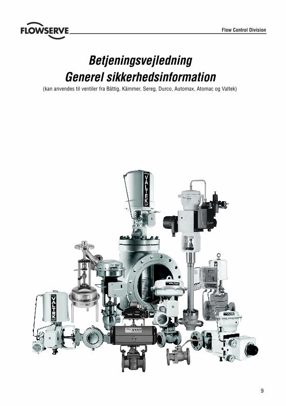
9
BetjeningsvejledningGenerel sikkerhedsinformation
(kan anvendes til ventiler fra Bättig, Kämmer, Sereg, Durco, Automax, Atomac og Valtek)
Flow Control Division
10
KORREKT ANVENDELSE AF FLOWSERVE-VENTILER OG -AKTUATORER
Sikkerhedsrelevante begreb
Signalordene FARE, ADVARSEL, FORSIGTIG og BEMÆRK anvendes i denne vejledning til at fremhævesærlige farer og/eller at give ekstra informationer om aspekter, der ikke omgående er indlysende.
FARE: Indikerer at død, alvorlige personskader og/eller betydelige materielle skader vil ske, hvispassende foranstaltninger ikke træffes.ADVARSEL: Indikerer at død, alvorlige personskader og/eller betydelige materielle skader kan ske,hvis passende foranstaltninger ikke træffes.FORSIGTIG: Indikerer at mindre personskader og/eller materielle skader kan ske, hvis passendeforanstaltninger ikke træffes.BEMÆRK: Indikerer og giver ekstra tekniske informationer, der endda for kvalificeret personalemåske ikke er selvfølgelige. Andre, ikke specielt fremhævede bemærkninger, med hensyn til transport,samling, anvendelse og vedligeholdelse og med hensyn til den tekniske dokumentation (fx ibetjeningsvejledningen, produktdokumentationen eller på selve produktet) skal også følges for atundgå fejl, der direkte eller indirekte kan forårsage alvorlige person- eller materielle skader.
AnvendelseFølgende instruktioner er beregnet som hjælp til udpakning, installering og vedligeholdelsesarbejde somkrævet i forbindelse med FLOWSERVE-produkter. Produktbrugere og vedligeholdelsespersonale skal læsedenne vejledning grundigt igennem før installering, brug eller vedligeholdelsesarbejde.
FARE: I de fleste tilfælde er FLOWSERVE-ventiler og -aktuatorer blevet konstruerede til særligeapplikationer (fx med hensyn til materiale, tryk, temperatur). Af denne årsag bør de ikke anvendestil andre applikationer uden forudgående aftale med producenten.
BeskyttelsestøjFLOWSERVE-produkter anvendes hyppigt under problematiske betingelser (fx ekstremt høje tryk, farlige,giftige eller korrosive stoffer). Især ventiler med bælgtætninger markerer sådanne betingelser. Underservice-, inspektions- eller reparationsarbejde skal det altid sikres, at trykket er fjernet fra ventilen ogaktuatoren samt at ventilen er blevet rengjort og er fri for skadelige stoffer. I sådanne tilfælde skal der isærtages højde for personlig beskyttelse (beskyttelsestøj, handsker, briller osv.).
Kvalificeret personaleKvalificeret personale er personer, der på grund af deres uddannelse, erfaring og indføring samt viden omrelevante normer, specifikationer, forskrifter om ulykkesforebyggelse og driftsforhold er blevet autoriseret afanlæggets ejer til at udføre det nødvendige arbejde og som kan registrere og undgå mulige farer.
ReservedeleAnvend kun originalreservedele fra FLOWSERVE. FLOWSERVE overtager intet ansvar for skader på grund afanvendelse af reservedele eller sikringsmaterialer fra andre producenter. Hvis FLOWSERVE-produkter (isærtætningsmaterialer) er blevet lagret i længere perioder, skal disse efterses for korrosion eller andre skaderfør brug af disse produkter. Brandværn for FLOWSERVE-produkter skal slutbrugeren stille til rådighed.
STOP!
11
STOP!
UDPAKNINGHver levering har en følgeseddel. Under udpakningen skal alle leverede ventiler og tilbehør kontrolleres ihenhold til denne følgeseddel.Større ventiler kan løftes ved hjælp af remmer på bærestykket, eller hvis forhånden ved hjælp af løfteringeneeller øjeboltene, der af denne årsag er forhånden. Hvis remme anvendes, skal de fastgøres således, at detyderrørsystemet eller monteringsdele ikke beskadiges.
ADVARSEL: Hvis remme anvendes, skal der tages højde for at ventilens tyngdepunkt kan være overløftepunktet. I dette tilfælde skal ventilen sikres eller afstives mod rotation for at undgå beskadigelsereller personskader.
Transportskader skal omgående meddeles vognmanden.
I tilfælde af uoverensstemmelser kontakt Deres nærmeste FLOWSERVE-salgskontor.
INSTALLATION
FARE: Før installering skal ordrenummer, serienummer og/eller mærkepladenummeret kontrolleresfor at sikre, at ventilen/aktuatoren er passende til den beregnede anvendelse.
Forlængelser, der er beregnet til varmebortledning eller opvarmning, må ikke isoleres.Rørledninger skal indrettes nøjagtigt for at sikre, at ventilen kan monteres spændingsfri.
IBRUGTAGNINGRørsystemet skal rengøres før installering.Om muligt skal ventilen installeres i en lodret position (aktuator på toppen) for at gørevedligeholdelsesarbejde nemmere. En lodret installeringsposition er vigtig i forbindelse medlavtemperatursopgaver for at holde afstanden mellem pakningsmaterialet og mediet så stor som mulig.Pakningsmaterialet holder bibeholder den omgivende temperatur således så meget som muligt.
BEMÆRK: Forlængelser, der er beregnet til varmebortledning eller opvarmning, må ikke isoleres.
Der skal sørges for at lade tilstrækkelig plads tilbage oven over aktuatoren for at muliggøre afmontering afproppen fra ventillegemet. Se installations-, betjenings- og vedligeholdelsesmanualen (IOM) med hensyn tildetaljerede informationer.
Efter installering skal gennemstrømsretningen kontrolleres igen. Gennemstrømsretningen kan ses på pilenpå ventilen.
Hvis ventilen skal svejses ind på linien, skal det sikres, at ventilen er beskyttet mod for megen varme.Svejsning skal foretages af kvalificerede svejsere.
Tilslutning af forsyningstryk og signalledninger.Styreventiler leveres med en manipulator. Endeforbindelserne for forsyningstryk og signal er tydeligtmarkerede. Aktuator og manipulator kan anvendes til det max. forsyningstryk som angivet på produktionenog inden for de anvendelige IOM’er. Hvis forsyningstrykket overstiger det angivne tryk, anbefales entrykreduktionsstation. Hvis apparatluft ikke er til rådighed, installeres en olieudskiller/luftfilter i luftledningeni henhold til ISA-normen S7.3. Alle forbindelser skal være frie for lækager.
12
STOP!
HURTIG KONTROL
Før brug skal ventilerne kontrolleres på følgende måde:
Ventilen åbnes og lukkes og bevægelsen af aktuatorstemplet observeres. Bevægelsen skal forløbe glat.
Maksimalslaget kontrolleres gennem skift af signalet (dvs. pneumatisk / elektrisk signal).Alle lufttilslutninger kontrolleres for lækager.
Pakningsmøtrikken eller -møtrikkerne skal kontrolleres med hensyn til sikkert hold. Pakningsmøtrikken eller -møtrikkerne skal altid strammes lidt mere end håndfast, men kun så meget som nødvendigt for at undgålækager på spindlen (se tilsvarende IOM for detaljer).
BEMÆRK: En for meget strammet pakning kan forårsage betydelig pakningsslitage og forhindre fribevægelse af spindlen.
Den fejlfrie position skal kontrolleres. Til dette afbrydes forsyningstrykket og / eller det elektriske signal ogkontrollér, om ventilerne enten åbner eller lukker, som fastlagt.
Hvis temperatursvingninger forekommer, skal alle boltesamlinger og pakninger om nødvendigt strammes ogkontrolleres for lækager.
ALMEN VEDLIGEHOLDELSE
For at undgå mulige skader på personale eller produkter, skal sikkerhedsforskrifterne og de lokale sundheds- ogsikkerhedsregler følges strikt. Modificering af dette produkt, udskiftning med fremmeddele eller anvendelse afandre vedligeholdelsesprocedurer end beskrevet i denne vejledning kan påvirke ydelsen drastisk og forårsagefarer for personale og udstyr samt gøre gældende garantikrav ugyldige.
FARE: Mellem aktuator og ventil er der bevægelige dele. For at undgå skader, skal hænder, hår og tøjholdes borte fra alle bevægelige dele under brug af ventilen.
Svejsning i forbindelse med reparation eller tilslutning af ventilen må kun udføres af uddannet og kvalificeretsvejsepersonale.Bortset fra brugsanvisningen og de gældende obligatoriske forskrifter om ulykkesforebyggelse i det pågældendeland, skal alle gældende sikkerheds- og fagtekniske regler følges.
ADVARSEL: FØR produkter returneres til FLOWSERVE for reparation eller service, skal De sendeFLOWSERVE en attest om, at produktet er blevet dekontamineret og er rent. Flowserve modtager ingenleveringer, hvis attesten ikke er blevet forelagt (et formular kan rekvireres hos FLOWSERVE).
Opbevaring
FLOWSERVE-produkter fremstilles af forskellige materialer. Produkter, der ikke er fremstillet afkorrosionsbestandige materialer, er forsynet med tilsvarende beskyttelse. Dermed er FLOWSERVE-produktergodt beskyttede mod korrosion. Alligevel skal FLOWSERVE-produkterne altid opbevares hensigtsmæssigt i reneog tørre omgivelser.Plasthætter er fastgjort på flangesiderne for at forhindre indtrængen af fremmedmaterialer. Disse hætter bør ikkefjernes, før ventilen virkelig integreres i systemet.
13
Varianter af ventiler og aktuatorer
Det kan forekomme, at denne betjeningsvejledning af årsager med hensyn til overskueligheden ikke indeholderalle detaljerede informationer om de mulige produktvarianter, og den kan især ikke tage højde for ethverttænkeligt tilfælde af opstilling, drift eller vedligeholdelse. Derfor indeholder betjeningsvejledning stort set kunsådanne henvisninger, der er nødvendige for kvalificeret personale til korrekt specificeret anvendelse afproduktet. I tilfælde af uklarheder med hensyn til dette, især ved manglende produktspecifikke detaljeredeinformationer, skal de nødvendige afklaringer foranlediges via det vedkommende FLOWSERVE-salgskontor.
REGELMÆSSIG VEDLIGEHOLDELSE
Ventilernes korrekte funktion skal kontrolleres i regelmæssige intervaller (alt efter anvendelse og kritisk tilstand)som angivet forneden. Denne kontrol kan foretages i monteret tilstand og i mange tilfælde uden afbrydelse afproduktionen.
Tætningerne skal kontrolleres for lækager og om nødvendigt strammes skruerne.
Bælgtætningen og testforbindelsen - hvis installeret - kontrolleres for lækager udadtil.
Ventilen kontrolleres for skader på grund af korrosive rester eller korrosive dampe.
Ventilerne rengøres og efterlakeres om nødvendigt.
Pakbøsningerne kontrolleres for lækage og justeres i givet fald. Se installations-, betjenings- ogvedligeholdelsesmanualen (IOM) med hensyn til detaljerede informationer.
BEMÆRK: En for meget strammet omløbermøtrik kan forårsage betydelig pakningsslitage og forhindrefri bevægelse af spindlen.
Om muligt åbnes og lukkes ventilen, og maksimalslaget samt den glatte bevægelse af spindlen kontrolleres.Uregelmæssig bevægelse af spindlen kan være tegn på interne defekter.
BEMÆRK: Ved grafitpakninger er uregelmæssige bevægelser af spindlen mulige.
FARE: Hænder, hår, tøj osv. skal holdes borte fra alle bevægelige dele. I modsat fald kan alvorligekvæstelser være følgen.
Alt tilbehør skal kontrolleres for fast hold.
Om muligt afbrydes forsyningstrykket og den fejlfri position kontrolleres.Beskyttelsesbælgen kontrolleres for slitage.
Aktuatoren kontrolleres for lækager. Hertil sprøjtes huset, lufttilslutningerne og spindelføringen medlækagespray og der kontrolleres, om blærer danner sig.
Spindlen skal rengøres.
Luftfilteret kontrolleres, hvis installeret, og om nødvendigt udskiftes patronen.
BEMÆRK: Angående yderligere informationer kontakt Deres nærmeste FLOWSERVE-salgskontor. IOM’erkan også fås på engelsk, tysk, fransk og mange andre sprog.

14
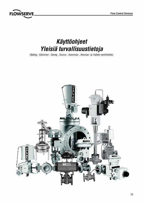
15
KäyttöohjeetYleisiä turvallisuustietoja
(Bättig-, Kämmer-, Sereg-, Durco-, Automax-, Atomac- ja Valtek-venttiileille)
Flow Control Division
16
STOP!
FLOWSERVE-VENTTIILIEN JA -TOIMILAITTEIDEN OIKEA KÄYTTÖ
Turvallisuusmerkinnät
Turvallisuusmerkintöjä VAARA, VAROITUS, HUOMIO ja HUOM. käytetään näissä ohjeissa korostamaan erikoisiavaaroja ja/tai lisätietojen antamiseen seikoista, jotka eivät ehkä ole heti ilmeisiä.
VAARA: merkitsee, että seurauksena on kuolema, vakavat vammat ja/tai huomattavat omaisuusvahingot,jos ei noudateta asianomaisia varotoimia.VAROITUS: merkitsee, että seurauksena voi olla kuolema, vakavat vammat ja/tai huomattavatomaisuusvahingot, jos ei noudateta asianomaisia varotoimia.HUOMIO: merkitsee, että seurauksena voi olla lievät vammat ja/tai omaisuusvahingot, jos ei noudatetaasianomaisia varotoimia.HUOM.: merkitsee ja tarjoaa teknisiä lisätietoja, jotka eivät ehkä ole täysin ilmeisiä edesammattihenkilöstölle. Kuljetusta, asennusta, käyttöä ja huoltoa sekä teknisiä dokumentteja koskevienmuiden (esim. käyttöohjeessa, tuotedokenteissa tai tuotteessa itsessään olevien) huomautusten, joitaei ole erityisemmin korostettu, noudattaminen on tärkeää, jotta vältetään virheet, jotka saattaisivat itseaiheuttaa välittömästi tai välillisesti vakavia vammoja tai ominaisuusvahinkoja.
KäyttöSeuraavat ohjeet on tarkoitettu olemaan apuna pakkauksesta purkamisessa, asennuksessa ja huoltotöissäFLOWSERVE-tuotteiden vaatimalla tavalla. Tuotteen käyttäjien ja huoltohenkilöstön tulisi lukea perusteellisestiläpi tämä lehtinen ennen asennusta, käyttöä tai kaikenlaisia huoltotöitä.
VAARA: FLOWSERVE-venttiilit ja toimilaitteet on tarkoitettu useinkin määrättyyn käyttöön (esim.väliaineen, paineen tai lämpötilan suhteen). Tästä syystä niitä ei saisi käyttää muissa käyttötapauksissaneuvottelematta tästä ensiksi valmistajan kanssa.
Suojavaatteet
FLOWSERVE-tuotteita käytetään usein ongelmasovelluksissa (esim. äärimmäisen korkea paine, vaaralliset,myrkylliset tai syövyttävät väliaineet). Tietyt paljetiivisteillä varustetut venttiilit soveltuvat tällaisiinkäyttötapauksiin. Varmista aina ennen huolto-, tarkastus- tai korjaustöitä, että venttiilistä ja käyttölaitteesta onpoistettu paine ja että venttiili on puhdistettu ja ettei se sisällä haitallisia aineksia. Kiinnitä tällaisissa tapauksissaerityistä huomiota henkilökohtaiseen suojaukseen (suojavaatteet, käsineet, suojalasit jne.).
Ammattitaitoinen henkilöstö
Ammattitaitoista henkilöstöä ovat henkilöt, jotka laitoksen turvallisuudesta vastuussa olevat henkilöt ovatvaltuuttaneet heidän koulutuksensa, kokemuksensa ja käyttöopetuksen perusteella sekä asianomaistenstandardien, teknisten vaatimusten, tapaturmantorjuntamääräysten ja käyttöolosuhteiden tuntemuksenperusteella suorittamaan tarpeelliset työt, ja jotka pystyvät havaitsemaan ja välttämään mahdolliset vaarat.
Varaosat
Käytä ainoastaan alkuperäisiä FLOWSERVE-varaosia. FLOWSERVE ei voi ottaa vastuuta vahingoista, jotkajohtuvat vieraiden valmistajien varaosien tai kiinnitysmateriaalien käytöstä. Jos FLOWSERVE-tuotteita(erityisesti tiivistysmateriaaleja) on säilytetty pidemmän aikaa varastossa, tarkasta nämä osat ennen niidenkäyttöä, ettei niissä ole syöpymistä tai ettei niiden laatu ole muulla tavalla huonontunut. Loppukuluttajan onitsensä huolehdittava FLOWSERVE-tuotteiden paloturvallisuudesta.
17
STOP!
PURKAMINEN PAKKAUKSESTA
Jokainen toimitus sisältää pakkausluettelon. Tarkasta kaikki toimitetut venttiilit ja lisävarusteet pakkauksestapurkaessasi tämän pakkausluettelon perusteella.
Suuremmat venttiilit voidaan nostaa kiinnittämällä köydet runkoon tai mahdollisesti venttiileihin asennettuihinnostokorvakkeisiin tai silmukkapultteihin. Jos käytät köysiä, kiinnitä ne siten, etteivät toimilaiteputkitus taikiinnitysosat vaurioidu.
VAROITUS: Jos käytät köysiä, ota huomioon, että venttiilin painopiste saattaa olla nostopistettäkorkeammalla. Tässä tapauksessa varmista tai tue venttiili kääntymisen varalta estääksesi vauriot jahenkilövammat.
Ilmoita kuljetusvahingot välittömästi kuljetusliikkeelle.
Epäselvissä tapauksissa ota yhteys lähimpään FLOWSERVE-myyntiliikkeeseen.
ASENNUS
VAARA: Tarkista ennen asennusta tilaus-nro, sarja-nro ja/tai kilpi-nro varmistaaksesi, että venttiili/toimilaite on oikea aiottuun tarkoitukseen.
Älä eristä osia, jotka on tarkoitettu lämmön tai kylmän haihduttamiseen.
Putket on kohdistettava tarkasti, jotta venttiili ei joudu jännitykseen.
KÄYTTÖÖNOTTO
Puhdista putket ennen asennusta.
Asenna venttiili mahdollisuuksien mukaan pystyasentoon (käyttölaite ylhäällä) huollon helpottamiseksi.Pystyasennus on tärkeää matalalämpösovelluksissa, jotta tiivistemateriaalin ja väliaineen etäisyys pysyymahdollisimman suurena. Tiivistemateriaalin lämpötila pysyy näin mahdollisimman lähellä ympäristönlämpötilaa.
HUOM.: Älä eristä jatkeita, jotka on tarkoitettu kuuman tai kylmän lämpötilan tasaamiseen.
Varmista, että toimilaitteen yläpuolelle jää tarpeeksi tilaa huoltoa varten, niin että venttiilin kara voidaan irrottaaventtiilirungosta. Ks. lisätietoja asennus-, käyttö- ja huoltokäsikirjasta.
Tarkasta virtaussuunta asennuksen jälkeen uudelleen. Virtaussuunta on merkitty nuolella venttiiliin.
Jos venttiili on hitsattava kiinni putkistoon, varmista, että venttiili on suojattu korkeilta lämpötiloilta. Hitsaustöitäsaa suorittaa vain ammattitaitoinen hitsaaja.
Syöttöpaineen ja signaalijohtojen liitäntä.
Säätöventtiilit on varustettu asennoittimella. Syöttöpaineen ja signaalin pääteliittimet on merkitty selvästi.Toimilaite ja asennoitin soveltuvat maksimisyöttöpaineelle, joka on ilmoitettu tuotteessa ja asianomaisessaasennus-, käyttö- ja huoltokäsikirjassa. Jos syöttöpaine ylittää määrätyn paineen, tarvitaanpaineenalennusasema. Jos instrumentti-ilmaa ei ole käytettävissä, asenna öljynerotin/ilmasuodatinilmantulojohtoon ISA-standardin S7.3 mukaisesti. Kaikkien liitäntöjen täytyy olla vuotamattomia.
18
STOP!
PIKATARKASTUS
Tarkasta venttiili ennen käyttöä seuraavasti:
Avaa ja sulje venttiili ja tarkkaile toimilaitteen karan liikettä. Liikkeen täytyy olla tasainen.
Tarkasta iskun maksimipituus muuttamalla signaalia (esim. pneumaattista/sähköistä signaalia).
Tarkasta kaikki ilmaliitännät, ettei niissä ole vuotoja.
Tarkasta poksitiivisteiden mutterit, että ne ovat tarpeeksi kireällä. Poksitiivisteiden muttereiden tulisi olla hiemankäsivaraista kireämmällä; kiristä kuitenkin vain niin paljon kuin on välttämätöntä karan vuotojen estämiseksi (ks.lisätietoja vastaavasta käsikirjasta).
HUOM.: Jos poksitiiviste kiristetään erittäin kireälle, se voi kulua voimakkaasti eikä kara voi liikkua vapaasti.
Tarkasta oikea toimisuunta katkaisemalla syöttöpaine ja/tai sähköinen signaali ja tarkkaile, aukeaako jasulkeutuuko venttiili oikealla tavalla.
Jos lämpötila vaihtelee, kiristä kaikki pulttiliitokset ja tiiviste tarpeen mukaan ja tarkasta, onko vuotoja.
YLEINEN HUOLTO
Henkilövammojen ja tuotevaurioiden välttämiseksi on noudatettava tarkasti turvallisuusmääräyksiä ja paikallisiaterveys- ja turvallisuussäännöksiä. Tämän tuotteen muuttaminen, ei-alkuperäisten osien käyttö tai sellaisethuoltotoimenpiteet, joita ei ole selostettu tässä ohjeessa, voivat vaikuttaa huomattavasti toimintaan ja ollavaarallisia henkilöstölle, ja aiheuttaa takuuoikeuksien menetyksen.
VAARA: Toimilaitteen ja venttiilin välissä on liikkuvia osia. Loukkaantumisen välttämiseksi pidä kädet,hiukset ja vaatteet loitolla kaikista liikkuvista osista venttiilin toimiessa.
Hitsaustöitä venttiilin korjaamiseksi tai liittämiseksi saa suorittaa vain koulutettu ja ammattitaitoinenhitsaushenkilöstö.
Käyttöohjeiden ja kyseisessä maassa voimassa olevien pakollisten tapaturmantorjuntamääräysten lisäksi onnoudatettava hyväksyttyjä turvallisuussääntöjä ja tekniikan sääntöjä.
VAROITUS: ENNEN KUIN tuote palautetaan FLOWSERVE-asiakaspalvelulle korjattavaksi tai huollettavaksi,FLOWSERVE-asiakaspalvelulle on toimitettava todistus, jossa vahvistetaan, että tuote on dekontaminoituja puhdistettu. Flowserve ei hyväksy toimituksia, jos todistusta ei ole toimitettu (lomaketta on saatavissaFLOWSERVE-ltä).
Varastointi
FLOWSERVE-tuotteet valmistetaan erilaisista materiaaleista. Tuotteet, joita ei ole valmistettukorroosionkestävästä materiaalista, on suojattu asianmukaisesti. Toisin sanoen FLOWSERVE-tuotteet on suojattuhyvin korroosiota vastaan. Tästä huolimatta FLOWSERVE-tuotteita on aina säilytettävä puhtaassa, kuivassaympäristössä. Laippojen otsapuolelle on kiinnitetty muovikansi estämään vieraiden esineiden pääsyn sisään.Näitä suojuksia ei saa poistaa, ennen kuin venttiili asennetaan järjestelmään.
19
Venttiili- ja toimilaitemuunnelmat
Nämä ohjeet eivät voi kattaa kaikkien mahdollisten tuotemuunnelmien kaikkia yksityiskohtia eivätkä ne erityisestivoi tarjota tietoja kaikkia mahdollisia asennus-, käyttö- tai huoltotapauksia varten. Toisin sanoen ohjeet sisältävätnormaalisti vain määräyksiä, joita ammattihenkilöstön on noudatettava, käytettäessä tuotetta sille määrättyyntarkoitukseen. Jos tämän suhteen on epäselvyyttä erityisesti tuotekohtaisten tietojen puuttuessa, lisätietoja onsaatavissa asianomaiselta FLOWSERVE-myyntiliikkeeltä.
SÄÄNNÖLLINEN HUOLTO
Tarkasta venttiili säännöllisin väliajoin (käyttötapauksesta ja sen vaarallisuudesta riippuen), että se toimii oikein,seuraavasti. Tämä tarkastus voidaan suorittaa venttiilin ollessa asennettuna paikalleen ja useimmissatapauksissa keskeyttämättä tuotantoa.
Tarkasta tiivisteet, etteivät ne vuoda, ja kiristä tarvittaessa kiinnittimet.
Tarkasta paljetiiviste ja sen mahdollinen tarkastusliitäntä, ettei niissä ole ulkopuolisia vuotoja.
Tarkasta venttiili, etteivät syövyttävät jäänteet tai höyryt ole sitä vaurioittaneet.
Puhdista venttiili ja maalaa se tarvittaessa uudelleen.
Tarkasta tiivistysholkit, etteivät ne vuoda. Säädä tarpeen mukaan. Ks. lisätietoja asennus-, käyttö- jahuoltokäsikirjasta.
HUOM.: Jos poksitiiviste kiristetään erittäin kireälle, se voi kulua voimakkaasti eikä kara voi liikkua vapaasti.
Avaa ja sulje venttiili mahdollisuuksien mukaan ja tarkasta karan maksimi-iskuliike ja esteetön kulku. Karanepäsäännöllinen liike saattaa olla merkki sisäisistä vioista.
HUOM.: Jos venttiilissä on grafiittitiiviste, kara saattaa liikkua epäsäännöllisesti.
VAARA: Pidä kädet, hiukset, vaatteet jne. poissa kaikkien liikkuvien osien läheltä. Muussa tapauksessaseurauksena voivat olla vakavat vammat.
Tarkasta kaikkien lisäosien kiinnitys.
Katkaise mahdollisuuksien mukaan syöttöpaine ja tarkasta oikea toimisuunta.
Tarkasta karan suojuksen kunto.
Tarkasta toimilaite, ettei se vuoda, sumuttamalla vuodontarkastussumutetta toimilaitteen runkoon,ilmaliitäntöihin ja karan ohjaimeen, ja tarkasta, muodostuuko kuplia.
Puhdista kara.
Tarkasta mahdollisesti asennettu ilmasuodatin ja vaihda tarvittaessa suodattimen patruuna.
HUOM.: Lisätietoja varten ota yhteys lähimpään FLOWSERVE-liikkeeseen. Asennus-, käyttö- jahuoltokäsikirjoja on saatavissa englannin, saksan, ranskan ja monien muiden maiden kielellä.

20
21
BruksanvisningAllmän säkerhetsinformation
(gäller för Bättig-, Kämmer-, Sereg-, Durco-, Automax-, Atomac och Valtek-ventiler)
Flow Control Division
22
STOP!
RÄTT ANVÄNDNING AV FLOWSERVE VENTILER OCH STÄLLDON
Använda säkerhetstermer
Säkerhetstermerna FARA, VARNING, OBS och MÄRK används i de här anvisningarna för att markera särskilda(speciella) risker och/eller för att ge ytterligare information som kanske inte är självklar.
FARA: anger att dödsfall, allvarlig personskada och/eller betydande sakskada inträffar om rättförsiktighetsåtgärder inte vidtas.VARNING: anger att dödsfall, allvarlig personskada och/eller betydande sakskada kan inträffa om rättförsiktighetsåtgärder inte vidtas.OBS: anger att lindrigare personskada och/eller mindre sakskada kan inträffa om rätt försiktighetsåtgärderinte vidtas.MÄRK: anger och tillhandahåller ytterligare teknisk information som kanske inte är alldeles självklar ensför kvalificerad personal. Det är viktigt att även andra anmärkningar, som inte är speciellt utmärkta, följsnär det gäller transport, montering, drift och underhåll samt i teknisk dokumentation (t.ex. idriftsanvisning, produktdokumentation eller på själva produkten) för att undvika fel som i sig självadirekt eller indirekt kan orsaka allvarlig personskada eller betydande sakskada.
Användning
Följande anvisningar är avsedda att vara till hjälp vid uppackning, montering och underhåll av FLOWSERVE-produkterna. Produktanvändare och underhållspersonal bör läsa den här informationen före montering, drifteller underhållsarbete.
FARA: I de flesta fall är FLOWSERVE ventiler och ställdon konstruerade för speciella tillämpningar (t.ex.med avseende på medium, tryck, temperatur). Av denna anledning bör de inte användas inom andratillämpningar utan att tillverkaren först har rådfrågats.
Personlig skyddsutrustning
FLOWSERVE-produkterna används ofta i krävande installationer (problematiska tillämpningar) (t.ex. extremthöga tryck, på farliga, giftiga eller frätande medier). Ventiler med bälgtätning används ofta inom sistnämndaområden. (I synnerhet ventiler med bälgtätningar används inom sådana områden.) Se alltid till att ventil ochställdon är tryckavlastade och att ventilen har rengjorts och är fri från farliga ämnen innan service, inspektioneller reparationsarbeten utförs. I sådana fall ska personlig skyddsutrustning (skyddskläder, handskar, glasögonetc.) användas.
Kvalificerad personal
Kvalificerad personal är personer som på grund av utbildning, erfarenhet och upplärning samt sina kunskaperom gällande normer, specifikationer, arbetarskyddsföreskrifter och driftsförhållanden har fått behörighet av demsom ansvarar för säkerheten inom företaget att utföra nödvändigt arbete och som kan upptäcka och undvikamöjliga risker.
Använd endast FLOWSERVE originalreservdelar. FLOWSERVE ansvarar inte för skador som inträffar till följd avatt reservdelar eller fastsättningsmaterial från andra tillverkare använts. Om FLOWSERVE-produkter (i synnerhettätningsmaterial) har lagrats en längre tid, ska de kontrolleras med avseende på korrosion eller försämringinnan de används. Slutanvändaren måste förse FLOWSERVE-produkter med brandskydd.
23
STOP!
UPPACKNING
I alla leveranser ingår en följesedel. Kontrollera samtliga levererade ventiler och tillbehör vid uppackningen medhjälp av följesedeln.
Större ventiler kan lyftas med stroppar och lyftok eller med hjälp av lyftöglor eller öglebultar om sådana finns.Om stroppar används, ska de fästas så att utvändiga rör eller anslutningsdelar inte skadas.
VARNING: Om stroppar används, tänk på att ventilens tyngdpunkt kan ligga ovanför lyftpunkten. Säkraeller stöd i så fall ventilen så att den inte kan rotera för att förhindra skada på utrustning eller personer.
Rapportera omedelbart transportskador (transportskador omedelbart) till fraktföraren.
Kontakta din närmaste FLOWSERVE-återförsäljare, om något saknas.
MONTERING
FARA: Kontrollera ordernr, serienr och/eller märkningsnr före montering, så att ventilen/ställdonet ärkorrekt för den avsedda användningen.
Isolera inte ventildelar (skarvstycken) som är avsedda för värmning eller kylning ex.vis förlängd överdel.Mantlade ventiler
bör isoleras om det finns risk för brännskador.
Rörledningar måste riktas upp korrekt så att ventilen inte monteras med rörspänningar som överförs tillventilhuset.
IDRIFTTAGNING
Rengör rörledningar före montering.
Montera om möjligt ventilen i upprätt läge (ställdonet överst) för att underlätta underhållsarbete. Montering iupprätt läge är viktigt vid lågtemperaturtillämpningar för att avståndet mellan packningsmaterialet och medietska bli så stort som möjligt. Packningsmaterialet behåller då omgivningstemperaturen så mycket som möjligt.
MÄRK: Isolera inte de delar av ventilen (skarvstycken) som är avsedda för värmning eller kylning.
Se till att det finns tillräcklig fri höjd ovanför ställdonet för att överdelen ska kunna demonteras frånventilkroppen. Se monterings-, drifts- och underhållshandboken för mer information.
Kontrollera flödesriktningen igen efter montering. Flödesriktningen anges med en pil på ventilen.
Se till att ventilen skyddas mot för kraftig värme, om den ska svetsas i ledningen. Svetsning måste utföras avbehörig svetsar.
Anslutning av matningstryck och signalledningar.
Reglerventiler är försedda med en lägesställare. (Änd) Luftanslutningarna för matningstryck och signal är tydligtmarkerade. (Ställdon och lägesställare lämpar sig för det max. matningstryck som anges på produkten och irespektive användarhandbok.)
Ställdon och lägesställare får matas med maximalt det lufttryck som anges på produkten och/eller i respektiveanvändarhandbok
Om matningstrycket överskrider det specificerade högsta tillåtna trycket, krävs en tryckreduceringsstation. Ominstrumentluft inte finns tillgänglig, ska ett oljeseparations-/luftfilter monteras i luftinloppsledningen enligt ISA-standard S7.3. Alla anslutningar måste vara täta. (läckfria).
24
STOP!
SNABBKONTROLL
Kontrollera ventilen på följande sätt innan den tas i drift:
Öppna och stäng ventilen och iakttag (ställdons) ventilspindelns rörelse. Rörelsen måste vara jämn.
Kontrollera max. slag genom att ändra styrsignalen (signal) (dvs. pneumatisk / elektrisk signal) från min. tillmax.
Kontrollera alla luftanslutningar med avseende på läckor.
Kontrollera att (huv) glandmuttern (-muttrarna) är rätt åtdragen (åtdragna). (Huv) Glandmuttern (-muttrarna)ska dras åt något hårdare än med fingrarna, men ska bara dras åt så mycket som behövs för att förhindraläckage förbi packboxen. (se respektive användarhandbok för mer information).
MÄRK: En för hårt åtdragen huvmutter kan orsaka för stort slitage på packboxen och hindraspindelns rörelse.
Kontrollera felsäkert läge. Gör detta genom att välja matningstryck och / eller elektrisk signal och iaktta omventilen öppnar och stänger som den ska.
Om temperaturpendling uppstår, dra vid behov åt alla bultanslutningar och packningar och kontrollera om detfinns läckor.
ALLMÄNT UNDERHÅLL
Säkerhetsföreskrifter och lokala regler för arbetarskydd måste alltid följas för att undvika möjliga skador påpersonalen eller utrustningen. Det är inte tillåtet att modifiera produkten, ersätta delar med delar från andratillverkare eller använda underhållsprocedurer som inte beskrivs i den här anvisningen, eftersom det drastisktkan påverka prestandan och innebära en risk för personal och utrustning samt innebär att garantin upphör attgälla.
FARA: Det finns rörliga delar mellan ställdonet och ventilen. Undvik skador genom att hålla händer, håroch kläder borta från alla rörliga delar vid drift av ventilen.
Svetsningsarbeten vid reparationer eller anslutning av ventilen får endast utföras av utbildad och behörigsvetspersonal.
Förutom driftsanvisningar och de obligatoriska arbetarskyddsregler som gäller i användarlandet måste även allaallmänna föreskrifter för säkerhet och teknik följas.
VARNING: INNAN produkter returneras till FLOWSERVE för reparation eller service, måste ett certifikattillställas FLOWSERVE som bekräftar att produkten har sanerats och är ren. Flowserve tar inte emotleveranser utan certifikat (blankett kan erhållas från FLOWSERVE).
Förvaring
FLOWSERVE-produkterna är tillverkade av olika material. Produkter som inte är tillverkade avkorrosionsresistenta material är försedda med lämpligt skydd. Detta innebär att FLOWSERVE-produkterna är välskyddade mot korrosion. Trots detta måste FLOWSERVE-produkterna alltid förvaras på rätt sätt i ren, torr miljö.Flänsar är försedda med plastlock för att förhindra att främmande material tränger in. Dessa lock får inte tas bortförrän ventilen monteras in i systemet.
25
Olikheter i ventiler och ställdon
Dessa anvisningar kan inte täcka alla detaljer för alla möjliga produktvarianter, och här ges inte information omalla möjliga exempel på installation, drift eller underhåll. Detta innebär att anvisningarna normalt endastomfattar det som ska följas av kvalificerad personal där produkten används för dess angivnaanvändningsområde. Om osäkerhet uppstår i detta avseende, i synnerhet om produktrelaterad informationsaknas, måste du kontakta din FLOWSERVE-återförsäljare för mer information.
PERIODISKT UNDERHÅLL
Kontrollera regelbundet (beroende på tillämpningen och hur kritisk funktionen är) att ventilerna fungerar enligtföljande: Denna kontroll kan göras efter montering och i många fall utan att produktionen behöver avbrytas.
Undersök packningar med avseende på läckor och dra åt fästelement om det behövs.
Kontrollera bälgpackning och testa anslutningen – om sådan finns – med avseende på utvändiga läckor.
Kontrollera ventilen med avseende på skada orsakad av frätande avlagringar eller ångor.
Rengör ventilerna och måla om vid behov.
Kontrollera packningsringarna med avseende på läckor. Justera vid behov. Se monterings-, drifts- ochunderhållshandboken för mer information.
MÄRK: En för hårt åtdragen glandmutter kan orsaka för stort slitage på packboxen och hindra spindelnsrörelse.
Om möjligt, öppna och stäng ventilen och kontrollera spindelns max. slag och att rörelsen är jämn. Omspindelns rörelse är oregelbunden, kan det tyda på invändiga skador.
MÄRK: Med grafitpackning kan spindelns rörelse vara oregelbunden.
FARA: Håll händer, hår, kläder etc. borta från rörliga delar. I annat fall kan allvarlig skada inträffa.
Kontrollera att alla tillbehör sitter ordentligt fast.
Om möjligt, stäng matningstrycket och kontrollera felsäkert läge.
Kontrollera skyddsbälgen med avseende på förslitning.
Kontrollera ställdonet med avseende på läckor. Gör detta genom att använda läckdetekteringsmedel påventilhus, luftanslutningar och spindelstyrning och kontrollera att inget läckage föreligger.
Rengör spindeln.
Kontrollera luftfiltret, om sådant finns, och byt insats vid behov.
MÄRK: Kontakta din FLOWSERVE-återförsäljare om du vill ha mer information. Användarhandböckerfinns på engelska, tyska, franska och flera andra språk.
26
ESSEN
Flow Control Division
DECLARATION OF CONFORMITY
with the Pressure Equipment Directive 97/23/EC
Herewith we, the manufacturer, Flowserve Essen GmbHManderscheidtstr. 19D- 45141 EssenGermany
Declare that the construction, manufacturing and testing of the pressure equipment is in conformancewith the directive 97/23/EC.
Description of the pressure equipment:
Control valves for process control
Conformity assessment modules:
Module H: Category III, Fluid Group 1 and 2 - Certificate N° 04 202 2 043 01 04016Pressure Accessories according to Article 1, section 2.1.4
Notified body that carried out the controls and monitors the Quality-system to 97/23/EC:
RWTÜV Anlagentechnik – N°0044Kurfürstenstr. 58D – 45138 EssenGermany
Name & address of the Notified body which carried out the inspection:
Not applicable
Referenced harmonised standards used:
EN19, EN287, EN288, EN10204, EN9001, EN10204, EN60534
References of other technical standards, specifications and European Directives used:
AD2000,DIN 3840
Machinery 98/37/EC,Electromagnetic Compatibility 89/336/EEC,Low voltage 72/23/EEC
Authorised Person for the Manufacturer within the European Community:
Name: Walter Friese
Title: QA-Manager
Signature: Date: 05/02/2002
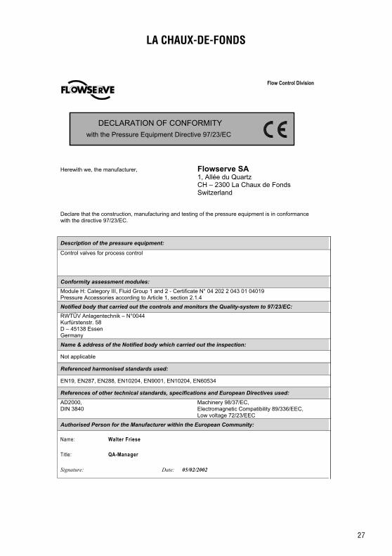
27
LA CHAUX-DE-FONDS
Flow Control Division
DECLARATION OF CONFORMITY
with the Pressure Equipment Directive 97/23/EC
Herewith we, the manufacturer, Flowserve SA1, Allée du QuartzCH – 2300 La Chaux de FondsSwitzerland
Declare that the construction, manufacturing and testing of the pressure equipment is in conformancewith the directive 97/23/EC.
Description of the pressure equipment:
Control valves for process control
Conformity assessment modules:
Module H: Category III, Fluid Group 1 and 2 - Certificate N° 04 202 2 043 01 04019Pressure Accessories according to Article 1, section 2.1.4
Notified body that carried out the controls and monitors the Quality-system to 97/23/EC:
RWTÜV Anlagentechnik – N°0044Kurfürstenstr. 58D – 45138 EssenGermany
Name & address of the Notified body which carried out the inspection:
Not applicable
Referenced harmonised standards used:
EN19, EN287, EN288, EN10204, EN9001, EN10204, EN60534
References of other technical standards, specifications and European Directives used:
AD2000,DIN 3840
Machinery 98/37/EC,Electromagnetic Compatibility 89/336/EEC,Low voltage 72/23/EEC
Authorised Person for the Manufacturer within the European Community:
Name: Walter Friese
Title: QA-Manager
Signature: Date: 05/02/2002

28
PERSHORE
Flow Control Division
DECLARATION OF CONFORMITY
with the Pressure Equipment Directive 97/23/EC
Herewith we, the manufacturer, Flowserve Pershore OperationsStation RoadPershoreWorcestershireWR10 2BZUnited Kingdom
Declare that the construction, manufacturing and testing of the pressure equipment is in conformancewith the directive 97/23/EC.
Description of the pressure equipment:
Customer: PO:Contract:
Description:Act model:Drg N°:Tag N°:
Conformity assessment module:
Valve Module H - Certificate N° 870643 Actuator Module H - Certificate N° 870643
Notified body that carried out the controls and monitors the Quality-system to 97/23/EC:
LRQA – N°0038HiramfordMiddlemarch Office VillageSiskin Drive, CoventryCV3 4FJUnited Kingdom
Valve PED Category:Actuator PED Category:EC Type examination Certificate: Not applicableEC Valve Design Exam. Certif.: DAD ECH-0060001-001-BRG.iss1EC Actuator Design Exam. Certif.: DAD ECH/0060001/2/BRG.iss1EC Certificate of Conformity:
Name & address of the Notified body which carried out the inspection:
Not applicable
Referenced harmonised standards used:
EN19, EN287, EN288, EN10204, EN9001, EN50018, EN50020, EN50039
References of other technical standards, specifications and European Directives used:
ANSI B16.34 Valve – Flanged/Threaded/Weld EndASME III, ANSI B16.5Valve data sheet:
Machinery 98/37/EC, CE Marking 93/68/EEC,Electromagnetic Compatibility 89/336/EEC,Low voltage 72/23/EEC, Pressure Equipment97/23/EC
Authorised Person for the Manufacturer within the European Community:
Name: Michael Wild
Title: QA-Manager
Signature: Date: 05/02/2002

29
THIERS
Flow Control Division
DECLARATION OF CONFORMITY
with the Pressure Equipment Directive 97/23/EC
Herewith we, the manufacturer, Flowserve SAS7, Avenue de la LibérationF- 63300 ThiersFrance
Declare that the construction, manufacturing and testing of the pressure equipment is in conformancewith the directive 97/23/EC.
Description of the pressure equipment:
Control valves for process control
Conformity assessment modules:
Module A (Cat. I); Module H (Cat. II & III) - Certificate N° DEP-LY-02-001
Notified body that carried out the controls and monitors the Quality-system to 97/23/EC:
GAPAVE - N°0060191, Rue Vaugirard75015 Paris
Name & address of the Notified body which carried out the inspection:
Not applicable
Referenced harmonised standards used:
EN19, EN287, EN288, EN9001, EN10204, EN50018, EN50020, EN50039
References of other technical standards, specifications and European Directives used:
ANSI B16.34,ASME VIII,CODAP 2000,AD2000
Machinery 98/37/EC, CE Marking 93/68/EEC,Electromagnetic Compatibility 89/336/EEC,Low voltage 72/23/EEC, Pressure Equipment97/23/EC
Authorised Person for the Manufacturer within the European Community:
Name: Daniel CHOMETTE
Title: QA-Manager
Signature: Date: 05/02/2002

30
AHAUS
Flow Control Division
DECLARATION OF CONFORMITY
with the Pressure Equipment Directive 97/23/EC
Herewith we, the manufacturer, Flowserve Ahaus GmbHVon Braun Strasse 19 aD – 48683 AHAUSGermany
Declare that the construction, manufacturing and testing of the pressure equipment is in conformancewith the directive 97/23/EC.
Description of the pressure equipment:
Atomac lined valve`sBTL / BTV Butterfly valveG411 - G431 - G4E
Mach I Plug valveT 41 - T42 - T43
Conformity assessment modules:
Module H – Category III – Fluid Group 1Lloyd`s Certificate No. 50006 / 1
Notified body that carried out the controls and monitors the Quality-system to 97/23/EC:
Lloyd`s Register HamburgMönkebergstrasse 27D-2095 HAMBURGGermany No. 0525
Name & address of the Notified body which carried out the inspection:
Not applicable
Referenced harmonised standards used:
EN 19 - EN558 - EN 10213 T3/T4 - EN 1563 - EN 1092 – EN 10204
References of other technical standards, specifications and European Directives used:
DIN 3230 T1/T3 - DIN 3840 - ISO 5211DIN 3337
Authorised Person for the Manufacturer within the European Community:
Name:Title: QA-Manager
Signature: EDP File valid without signature Date: 05/02/2002
Heiko Adorf

31
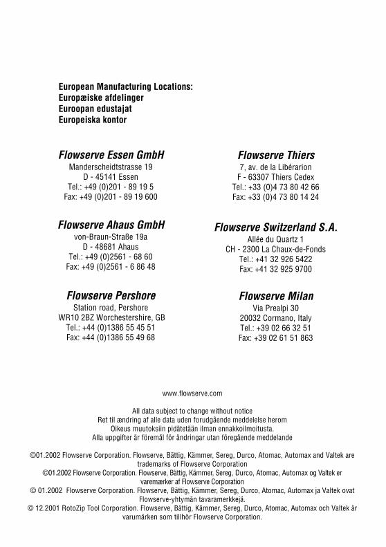
32
www.flowserve.com
All data subject to change without noticeRet til ændring af alle data uden forudgående meddelelse herom
Oikeus muutoksiin pidätetään ilman ennakkoilmoitusta.Alla uppgifter är föremål för ändringar utan föregående meddelande
©01.2002 Flowserve Corporation. Flowserve, Bättig, Kämmer, Sereg, Durco, Atomac, Automax and Valtek aretrademarks of Flowserve Corporation
©01.2002 Flowserve Corporation. Flowserve, Bättig, Kämmer, Sereg, Durco, Atomac, Automax og Valtek ervaremærker af Flowserve Corporation
© 01.2002 Flowserve Corporation. Flowserve, Bättig, Kämmer, Sereg, Durco, Atomac, Automax ja Valtek ovatFlowserve-yhtymän tavaramerkkejä.
© 12.2001 RotoZip Tool Corporation. Flowserve, Bättig, Kämmer, Sereg, Durco, Atomac, Automax och Valtek ärvarumärken som tillhör Flowserve Corporation.
Flowserve PershoreStation road, Pershore
WR10 2BZ Worchestershire, GBTel.: +44 (0)1386 55 45 51Fax: +44 (0)1386 55 49 68
Flowserve Switzerland S.A.Allée du Quartz 1
CH - 2300 La Chaux-de-FondsTel.: +41 32 926 5422Fax: +41 32 925 9700
Flowserve Ahaus GmbHvon-Braun-Straße 19a
D - 48681 AhausTel.: +49 (0)2561 - 68 60
Fax: +49 (0)2561 - 6 86 48
Flowserve Thiers7, av. de la Libérarion
F - 63307 Thiers CedexTel.: +33 (0)4 73 80 42 66Fax: +33 (0)4 73 80 14 24
Flowserve Essen GmbHManderscheidtstrasse 19
D - 45141 EssenTel.: +49 (0)201 - 89 19 5
Fax: +49 (0)201 - 89 19 600
European Manufacturing Locations:Europæiske afdelingerEuroopan edustajatEuropeiska kontor
Flowserve MilanVia Prealpi 30
20032 Cormano, ItalyTel.: +39 02 66 32 51Fax: +39 02 61 51 863