Embed Size (px)
Citation preview

AMP3 - 3-Way Lined Valves
Ahaus GmbHvon-Braun-Straße 19aD-48683 AhausPostfach 1162 D-48661 AhausTelefon: +49(0) 2561-686-100Fax: +49(0) 2561-686-200
Register: 17
Page: 1
Date: 06.2003
Revision: 03.2009
Technical Manual
Register 17CONTENS - AMP3
Contents Page
Technical Data AMP3-DIN .............................................................................................. 2
Technical Data AMP3-ANSI ............................................................................................. 3
MaterialSpecificationAMP3 ............................................................................................ 4
AssembyInstructionAMP3 .............................................................................................. 5
DiassembyInstructionAMP3 ........................................................................................... 6
AMP3-RecommendedTighteningTorques .................................................................... 7
AMP3withlockablehandlever ....................................................................................... 8
SwitchsymbolsAMP3L ................................................................................................... 9
SwitchsymbolsAMP3T ................................................................................................. 10
AMP3 - KvandCv - Data ................................................................................................. 12

AMP3 - 3-Way Lined Valves
Ahaus GmbHvon-Braun-Straße 19aD-48683 AhausPostfach 1162 D-48661 AhausTelefon: +49(0) 2561-686-100Fax: +49(0) 2561-686-200
Register: 17
Page: 2
Date: 06.2003
Revision: 03.2009
Technical Manual
Face to Face dimensions: DIN EN 558 (Basic series 1)Flange Connection: DINEn 1092-2
Technical Data AMP3 - DIN
weight
L - Ball T - Ball
DN / DIN L L/2 ØD R H
025 mm 160 80 20 160 125 kg 5,2 inch 6,3 3,15 0,79 6,3 4,92 lbs 11,5
040 mm 200 100 32 210 149 kg 12,0 inch 7,87 3,94 1,26 8,27 5,87 lbs 26,4
050 mm 230 115 40 210 165 kg 16,7 inch 9,06 4,53 1,57 8,27 6,5 lbs 36,8
080 mm 310 155 60 313 200 kg 32,0 inch 12,2 6,1 2,36 12,32 7,87 lbs 70,5
100 mm 350 175 75 313 220 kg 45,0 inch 13,78 6,89 2,95 12,32 8,66 lbs 99,2
150 mm 480 240 128 674 313,5 kg 136,5 inch 18,9 9,45 5,04 26,54 12,34 lbs 300,8
A-A A-A
A
ARH
DN
L L
DN
140 090 090080 135 040 100 065
060 170 110120 130
070 200 210
010 030 050 020 010 030 050 020
150
L/2
L/2
D
D

AMP3 - 3-Way Lined Valves
Ahaus GmbHvon-Braun-Straße 19aD-48683 AhausPostfach 1162 D-48661 AhausTelefon: +49(0) 2561-686-100Fax: +49(0) 2561-686-200
Register: 17
Page: 3
Date: 06.2003
Revision: 03.2009
Technical Manual
Technical Data AMP3 - ANSI
Face to Face dimensions: DIN EN 558 (Basic series 1)Flange Connection: ANSI B 16.5
weight
L - Ball T - Ball
DN / ANSI L L/2 ØD R H
1“ mm 160 80 20 160 125 kg 5,2 inch 6,3 3,15 0,79 6,3 4,92 lbs 11,5
1½“ mm 200 100 32 210 149 kg 12,0 inch 7,87 3,94 1,26 8,27 5,87 lbs 26,4
2“ mm 230 115 40 210 165 kg 16,7 inch 9,06 4,53 1,57 8,27 6,50 lbs 36,8
3“ mm 310 155 60 313 200 kg 32,0 inch 12,2 6,1 2,36 12,32 7,87 lbs 70,5
4“ mm 350 175 75 313 220 kg 45,0 inch 13,78 6,89 2,95 12,32 8,7 lbs 99,2
6“mm 480 240 128 674 313,5 kg 137,7 inch 18,9 9,45 5,04 26,54 12,34 lbs 303,5
A-A A-A
A
ARH
DN
L L
DN
140 090 090080 135 040 100 065
060 170 110120 130
070 200 210
010 030 050 020 010 030 050 020
150
L/2
L/2
D
D

AMP3 - 3-Way Lined Valves
Ahaus GmbHvon-Braun-Straße 19aD-48683 AhausPostfach 1162 D-48661 AhausTelefon: +49(0) 2561-686-100Fax: +49(0) 2561-686-200
Register: 17
Page: 4
Date: 06.2003
Revision: 03.2009
Technical Manual
Material Specification AMP3
No. Designation Pieces Material Material-No. / DIN ASTM / AISI
010 body 1 ductile iron / PFA ° EN-JS1049 (GGG-40.3) / A 395ductile iron / FEP ° DIN EN 1563
020 side piece 1 ductile iron / PFA ° EN-JS1049 (GGG-40.3) / A 395ductile iron / FEP ° DIN EN 1563
030 seat ring 3 PTFE pure - PTFE040 stem 1 stainless steel / PFA 1.4470 / DIN EN 10283 A 890 CD3MN050 ball 1 ductile iron / PFA ° EN-JS1049 (GGG-40.3) / A 395
ductile iron / FEP ° DIN EN 1563060 gland follower 1 stainless steel 1.4308 / DIN EN 10283 A 743 CF-8065 gland insert 1 PTFE-graphite070 hand lever
DN 1“ - 2“, DN 25 - 50 1 die cast metall (galvanized) ZP0410 / DIN EN 12844DN 3“ -4“, DN 080 - 100 1 ductile iron (galvanized) EN-GJS-50-7 (GGG-50)DN 6“, DN 150 1 steel (galvanized) 1.0037 / DIN EN 10025-2 A 283 B
080 stud bolt 1 set stainless steel 1.4301 / DIN EN 10088-3 A 193 B8090 hexagon nut 1 set stainless steel 1.4301 / DIN EN 10088-3 A 193 B8100 packing material 1 set PTFE
(chevron)110 hexagon nut 2 stainless steel 1.4301 / DIN EN 10088-3 A 194 8120 stud bolt 2 stainless steel 1.4301 / DIN EN 10088-3 A 193 B8130 locking position indicator 1 stainless steel 1.4301 / DIN EN 10088-3 AISI 304135 countersunk screw 1 stainless steel 1.4301 / DIN EN 10088-3 A 193 B8140 hexagon bolt 1 stainless steel 1.4301 / DIN EN 10088-3 A 193 B8150 serrated lock washer 2 stainless steel 1.4301 / DIN EN 10088-3 AISI 304170 grounding device 1 stainless steel 1.4310 / DIN EN 10270-3 AISI 301200 stop
DN 1“, 1½“, 2“, 3“, 1 steel (galvanized) 1.0037 / DIN EN 10025-2 A 283 BDN 080, 100 1 steel (galvanized) 1.0037 / DIN EN 10025-2 A 283 BDN 2“, 6“, 1 stainless steel 1.4104 / DIN EN 10088-3 AISI 430 FDN 025 - 050, 150 1 stainless steel 1.4104 / DIN EN 10088-3 AISI 430 F
210 hexagon bolt 1 stainless steel 1.4301 / DIN EN 10088-3 A 193 B8
°optional

AMP3 - 3-Way Lined Valves
Ahaus GmbHvon-Braun-Straße 19aD-48683 AhausPostfach 1162 D-48661 AhausTelefon: +49(0) 2561-686-100Fax: +49(0) 2561-686-200
Register: 17
Page: 5
Date: 06.2003
Revision: 03.2009
Technical Manual
Assemby Instruction AMP3
The general installation and maintenance instructions must be observed.
1. Screw stud bolts (120) into body (010).2. Insert the stem (040) from inside of the body in such a way that the flat side is parallel to
the body longitudinal axis.3. Insert the chevron packing (100).4. Install gland insert (065), gland follower (060) including the insert (065) as well as the
safety washers (150), hexagon nuts (110) and the grounding strap (170). Use the ground-ing strap also when the valve will be automated or mounted with a gear.
5. Install hand lever (070) on the stem (040) and tighten it using the position indicator (130) and hexagon bolt (140).
6. Fasten the position indicator (130) on the hand lever with the countersunk bolt (135).7. Insert the lower ball seat ring (030) into the body (010).8. Together with the second ball seat ring (030) insert the L- or T-ball (050) into the body. The
stem flats fit the ball flats. Pay attention to which switching symbol is required (see sepa-rate switching symbol charts).
9. Turn the ball (050) in that way that the closed side of the ball will show to the side piece connection.
10. Screw stud bolts (080) into side piece (020).11. Place the third ball seat ring (030) on the ball
(050) and install the side piece. Take care of the right position of the recess for the ball seat ring in the body.
12. Screw the hexagon nuts (090) on the stud bolts (080) and tighten them by crisscross method to recommended torques.
13. According to the configuration of the valve install either one or two stops (200) by using the hexa-gon bolts (210).
090
100
210
220
070
060
170
130
065
140
135
110
150
120
030
020
050
040
010
080
090

AMP3 - 3-Way Lined Valves
Ahaus GmbHvon-Braun-Straße 19aD-48683 AhausPostfach 1162 D-48661 AhausTelefon: +49(0) 2561-686-100Fax: +49(0) 2561-686-200
Register: 17
Page: 6
Date: 06.2003
Revision: 03.2009
Technical Manual
Diassemby Instruction AMP3
For all jobs which are to be carried out on an installed valve, the works safety requirements and the general accident prevention instructions must be observed. Moreover, the general installation and maintenance instructions for atomac fluorcarbon resin lined valves must be considered.
1. Prior to disassembly, the valve must be cleared of all fluid according to the above men-
tioned instructions. Particular care must be taken that during rinsing and draining of the piping, the valve is opened and closed repeatedly. These cycles (opening and closing) are to be repeated during draining of the piping. Only when following this procedure, it is en-sured that all remaining pressure inside the body (stem guide and ball seats) is eliminated.
2. For disassembly of the valve put it on a work bench with a soft cover (rubber mat). Re-move hexagon nuts (110) and lock washer (150).
3. Disassemble the hand lever (070) with the position indicator (130) by removing the hexa-gon bolt (140).
4. Remove grounding device (170), gland insert (065) and packing gland follower (060). If necessary stud bolts (120) can also be removed now.
5. Unscrew the hexagon nuts (090) and remove side piece (020) from the body (010).6. Remove the ball seat ring (030) out of the side piece (020).7. Including the ball seat ring (030) on side remove
the ball (050) out of the body (010).8. The lower ball seat ring (030) can easily be re-
moved now out of the body.9. Disassemble the stem (040) by pushing it down
through the body (010). Care must be taken not to damage the body liner.
10. Chevron packing (100) can be removed.11. If necessary, remove hand lever stop (s) (200) by
removing the hexagon bolt (s) (210).
090
100
210
220
070
060
170
130
065
140
135
110
150
120
030
020
050
040
010
080
090

AMP3 - 3-Way Lined Valves
Ahaus GmbHvon-Braun-Straße 19aD-48683 AhausPostfach 1162 D-48661 AhausTelefon: +49(0) 2561-686-100Fax: +49(0) 2561-686-200
Register: 17
Page: 7
Date: 06.2003
Revision: 03.2009
Technical Manual
AMP3 - Recommended Tightening Torques*
* maximumvalue
tie rods connection flange gland bolts
DN (080/090) (110/120/150)
Nm in.lbs Nm in.lbs Nm in.lbs
025 21 186 36 319 4 35 1“ 14 124 17 150 4 35
040 49 434 75 664 7 62 1½“ 52 460 39 345 7 62 050 70 620 95 841 7 62 2“ 75 664 79 699 7 62
080 61 540 75 664 8 71 3“ 65 575 129 1142 8 71
100 114 1009 87 770 8 71 4“ 116 1027 97 858 8 71
150 153 1354 130 1151 12 106 6“ 161 1425 129 1142 12 106

AMP3 - 3-Way Lined Valves
Ahaus GmbHvon-Braun-Straße 19aD-48683 AhausPostfach 1162 D-48661 AhausTelefon: +49(0) 2561-686-100Fax: +49(0) 2561-686-200
Register: 17
Page: 8
Date: 06.2003
Revision: 03.2009
Technical Manual
AMP3 with lockable hand lever
R
L
L/2
H
h
H2
DN
130
200 210 230
No. Designation Pieces Material Material-No. DIN ASTM / AISI
130 locking position indicator 1 stainless steel 1.4301 DIN 17440 AISI 304200 stop 1 stainless steel 1.4301 DIN 17440 AISI 430F210 hexagon bolt 1 stainless steel 1.4301 DIN 17440 A 193 B8230 locking bolt 1 stainless steell / duroplastic 1.4301 DIN 17440 AISI 304
DIN ANSI L L/2 H R H2 h
025 1“ mm 160 80 125 160 125 52 inch 6,3 3,15 4,92 6,3 4,9 2
040 1½“ mm 200 100 149 210 158 72 inch 7,87 3,94 5,87 8,27 6,22 2,83
050 2“ mm 230 115 165 210 163 82 inch 9,06 4,53 6,5 8,27 6,42 3,23
080 3“ mm 310 155 200 313 230 119 inch 12,2 6,10 7,87 12,32 9,06 4,69
100 4“ mm 350 175 220 313 242 132 inch 13,78 6,89 8,66 12,32 9,53 5,2
150 6“ mm 480 240 314 674 335 204 inch 18,9 9,45 12,34 26,54 13,19 8,03

AMP3 - 3-Way Lined Valves
Ahaus GmbHvon-Braun-Straße 19aD-48683 AhausPostfach 1162 D-48661 AhausTelefon: +49(0) 2561-686-100Fax: +49(0) 2561-686-200
Register: 17
Page: 9
Date: 06.2003
Revision: 03.2009
Technical Manual
zurück
Switchsymbols AMP3L
symbol No.1.1 - 180° switch
symbol No.1 - 90° switch
zurück
AMP3 - 3-Way Lined Valves
Ahaus GmbHvon-Braun-Straße 19aD-48683 AhausPostfach 1162 D-48661 AhausTelefon: +49(0) 2561-686-100Fax: +49(0) 2561-686-200
Register: 17
Page: 10
Date: 06.2003
Revision: 03.2009
Technical Manual
zurück
zurück
zurück
zurück
zurück
zurück
zurück
zurück
zurück
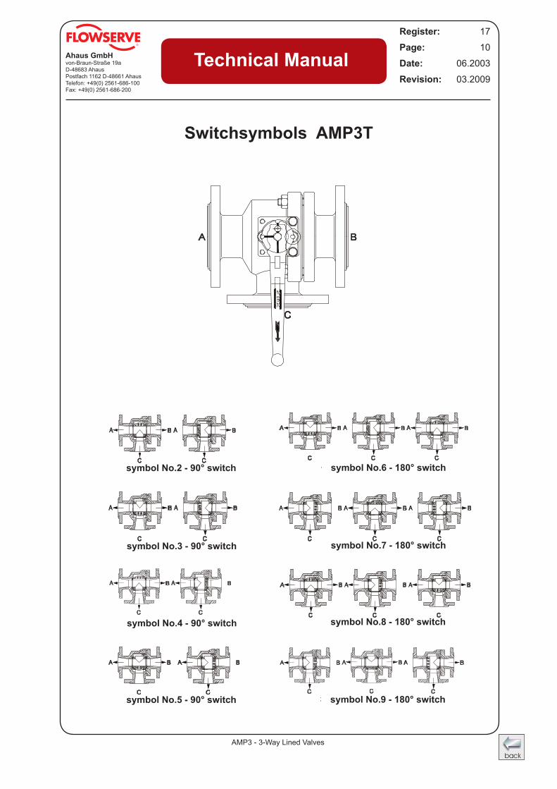
Switchsymbols AMP3T
symbol No.2 - 90° switch
symbol No.3 - 90° switch
symbol No.4 - 90° switch
symbol No.5 - 90° switch symbol No.9 - 180° switch
symbol No.8 - 180° switch
symbol No.7 - 180° switch
symbol No.6 - 180° switch
AMP3 - 3-Way Lined Valves
Ahaus GmbHvon-Braun-Straße 19aD-48683 AhausPostfach 1162 D-48661 AhausTelefon: +49(0) 2561-686-100Fax: +49(0) 2561-686-200
Register: 17
Page: 12
Date: 06.2003
Revision: 03.2009
Technical Manual
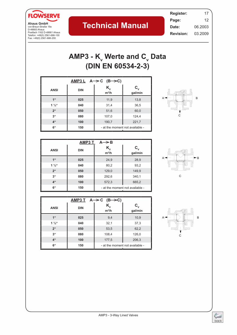
AMP3 - Kv Werte and Cv Data(DIN EN 60534-2-3)
AMP3 L A C (B C)
ANSI DINKV CV
m³/h gal/min
1“ 025 11,9 13,8
1 ½“ 040 31,4 36,5
2“ 050 51,6 60,0
3“ 080 107,0 124,4
4“ 100 190,7 221,7
6“ 150 0,0
AMP3 T A B
ANSI DINKV CV
m³/h gal/min
1“ 025 24,9 28,9
1 ½“ 040 80,2 93,2
2“ 050 129,0 149,9
3“ 080 292,6 340,1
4“ 100 572,3 665,2
6“ 150 0,0
AMP3 T A C (B C)
ANSI DINKV CV
m³/h gal/min
1“ 025 9,4 10,9
1 ½“ 040 32,1 37,3
2“ 050 53,5 62,2
3“ 080 108,4 126,0
4“ 100 177,5 206,3
6“ 150 0,0
B
C
A
B
C
A
B
C
A
- at the moment not available -
- at the moment not available -
- at the moment not available -