Embed Size (px)
Citation preview
Integration of Diesel Engine Technology to Meet
US EPA 2010 Emissions with Improved Thermal
Efficiency
Donald StantonResearch and TechnologyCummins Inc.
August 14, 2007 – DEER Conference
60
Bra
ke T
herm
al E
ffici
ency
(%)
55
50
45
40
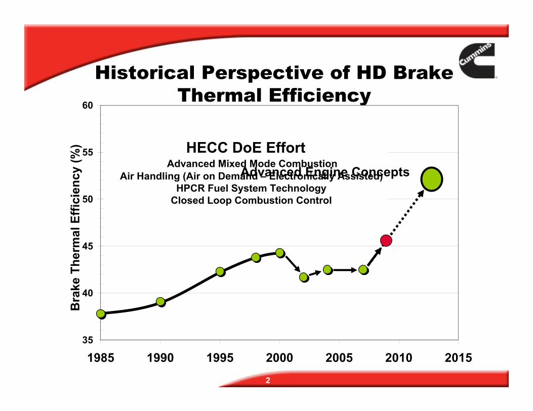
Historical Perspective of HD Brake Thermal Efficiency
HECC DoE Effort Advanced Mixed Mode Combustion
Air Handling (Air on Demand – Electronically Assisted) HPCR Fuel System Technology
Closed Loop Combustion Control
Advanced Engine Concepts
1985 1990 1995 2000 2005 2010 2015
2
35
0
0.2
0.4
0.6
0.8
bsNOx (g/bhp-hr)
Par
ticul
ate
Mat
ter (
g/bh
p-hr
)
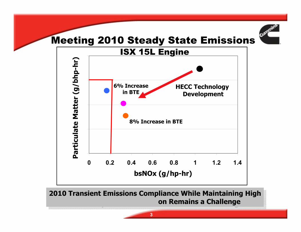
2010 Transient Emissions Compliance While Maintaining High
3
0 0.2 0.4 0.6 0.8 1 1.2 1.4
HECC Technology Development
8% Increase in BTE
6% Increase in BTE
Efficiency Clean Combustion Remains a ChallengeEfficiency Clean Combusti2010 Transient Emissions Compliance While Maintaining High
on Remains a Challenge
bsNOx (g/hp-hr)
Par
ticu
late
Mat
ter
(g/b
hp-
hr)
Meeting 2010 Steady State Emissions ISX 15L Engine
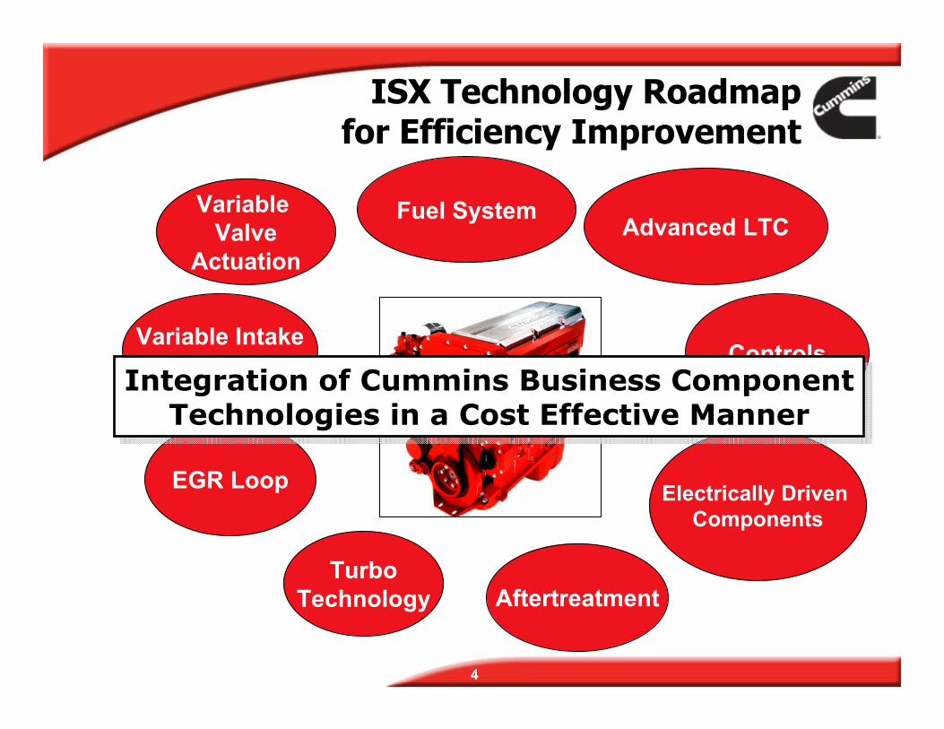
SwirlIntegration of Cummins Business Component
Technologies in a Cost Effective Manner
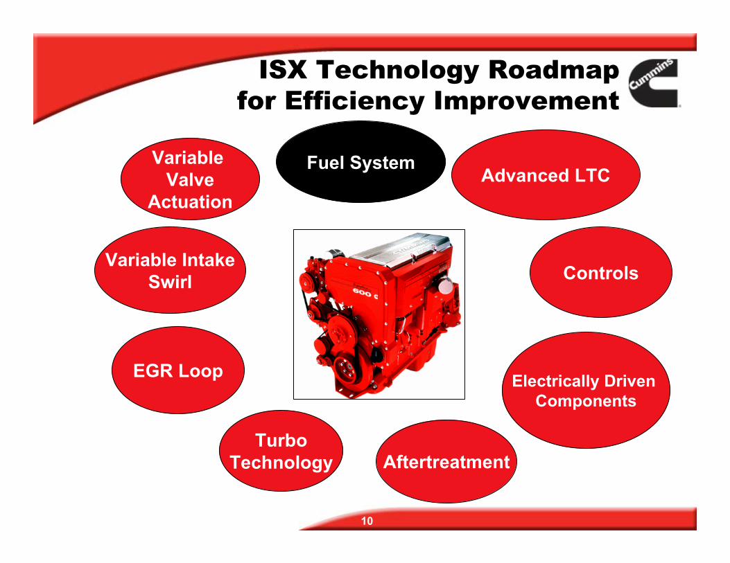
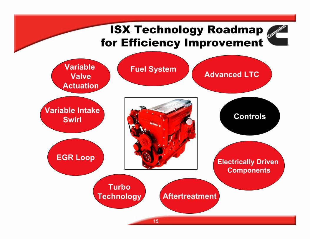
ISX Technology Roadmapfor Efficiency Improvement
Fuel System Advanced LTC
Variable Valve
Actuation
EGR Loop
ControlsVariable Intake
Electrically Driven Components
Turbo Technology Aftertreatment
Integration of Cummins Business Component Technologies in a Cost Effective Manner
4
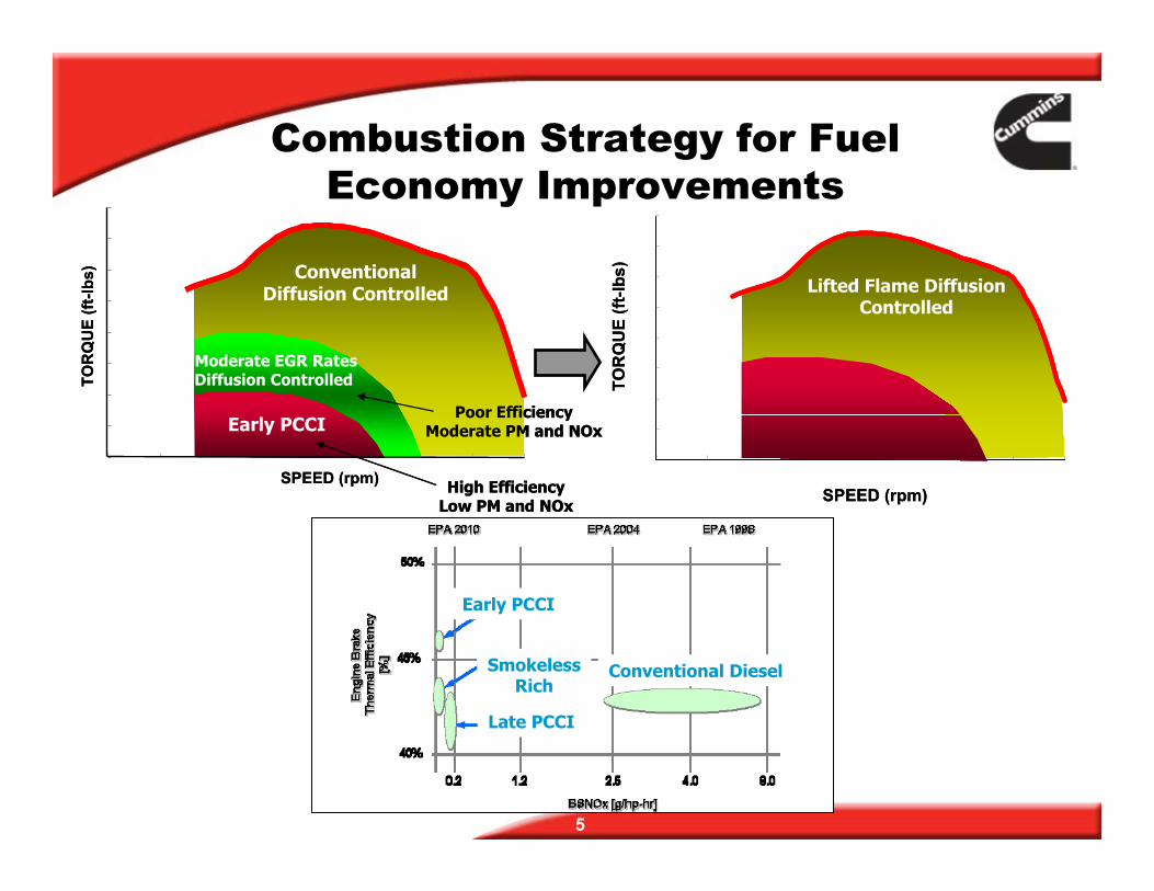
Early PCCI
ConventionalDiffusion Controlled
Moderate EGR RatesDiffusion Controlled
Poor EffiModerate
0
200
400
600
800
1000
1200
1400
400 600 800 1000 1200 1400 1600 1800 2000
Early PCCI
Lifted Flame DiffusionControlled
1600
0
200
400
600
800
1000
1200
1400
400 600 800 1000 1200 1400 1600 1800 2000
1600
5
Combustion Strategy for Fuel Economy Improvements
SPEED (rpm)
TOR
QU
E (ft
-lbs)
ciency PM and NOx
High Efficiency Low PM and NOx
SPEED (rpm)
TOR
QU
E (ft
-lbs)
ciencyPM and NOx
High EfficiencyLow PM and NOx
Early PCCI
Conventional Diffusion Controlled
Moderate EGR Rates Diffusion Controlled
Poor Effi Moderate
Early PCCI
Late PCCI
Smokeless Rich
Conventional Diesel
TOR
QU
E (ft
-lbs)
TOR
SPEED (rpm)SPE
Early PCCI
Lifted Flame Diffusion Controlled
QU
E (ft
-lbs)
ED (rpm)
0.00%
1.00%
2.00%
3.00%
4.00%
5.00%
6.00%
7.00%
8.00%
9.00%
10.00%
2350 2400 2450 2500 2550 2600 2650 2700 2750Maximum Alpha 0 Rail Pressure
Incr
ease
inFT
Pbs
PM
0%
2%
4%
6%
8%10%
12%
14%
Per
cen
t In
crea
se in
FTP
bsD
PM
16%
Rail Pressure (bar)
18%20%
0.00%
1.00%
2.00%
3.00%
4.00%
5.00%
6.00%
7.00%
8.00%
9.00%
10.00%
2350 2400 2450 2500 2550 2600 2650 2700 2750Maximum Alpha 0 Rail Pressure
Incr
ease
inFT
Pbs
PM
0%
2%
4%
6%
8%10%
12%
14%
Per
cen
t In
crea
se in
FTP
bsD
PM
16%
Rail Pressure (bar)
18%20%
Rail Pressure (bar)
1600 RPM at 100% Load1600 RPM at 100% Load
6
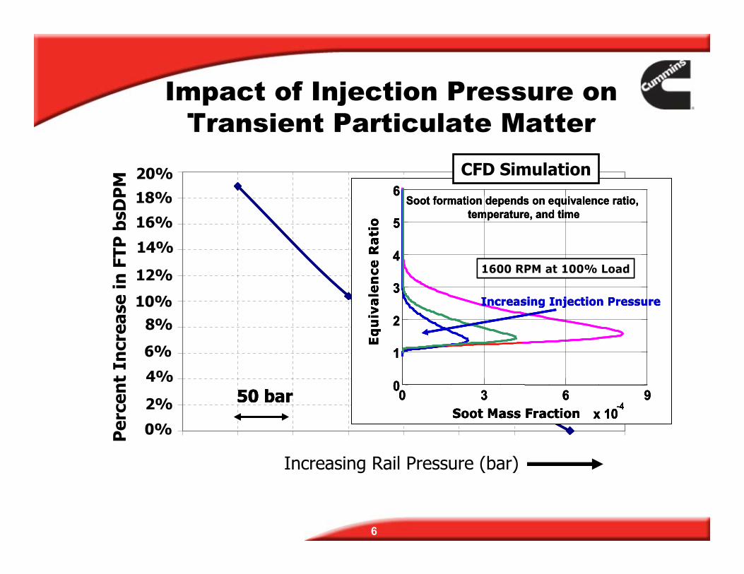
Impact of Injection Pressure on Transient Particulate Matter
50 bar50 bar
0%
2%
4%
6%
8% 10%
12%
14%
Per
cen
t In
crea
se in
FTP
bsD
PM
16%
50 bar
18% 20%
Soot formation depends on equivalence ratio, temperature, and time
Eq
uiv
ale
nce
Ra
tio
Soot Mass Fraction 0 3 6 9
x 10-4
0
1
2
3
4
5
6
Increasing Injection Pressure
SSoot formation depends on equivalence ratio,temperature, and time
Eq
uiv
ale
nce
Ra
tio
Soot Mass Fraction0 3 6 9
x 10-4
0
1
2
3
4
5
6
Increasing Injection Pressure
oot formation depends on equivalence ratio,temperature, and time
Eq
uiv
ale
nce
Ra
tio
Soot Mass Fraction0 3 6 9
x 10-4x 10-4
0
1
2
3
4
5
6
1600 RPM at 100% Load
CFD Simulation
Increasing Rail Pressure (bar)
Increasing Injection Pressure
ection
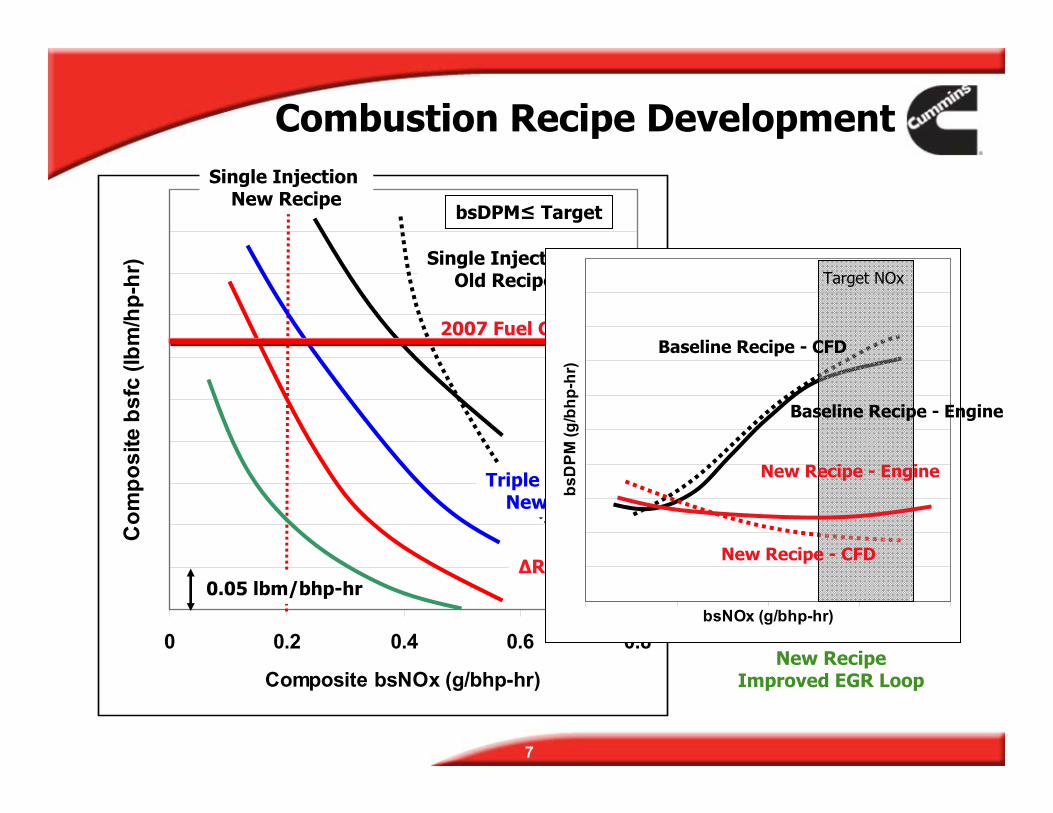
Triple Injectionail Pressure 300 bar
New RecipeTriple Injection
ΔRail Pressure 300 bar
nsumption
7
0 0.2 0.4 0.6 0.8
Composite bsNOx (g/bhp-hr)
Com
posi
te b
sfc
(lbm
/hp-
hr)
0.05 lbm/bhp-hr
bsDPM≤ Target
Single Injection New Recipe
Single Injection Old Recipe
Triple Inj New Recipe
ΔR
Combustion Recipe Development
New Recipe Improved EGR Loop
2007 Fuel Co
bsNOx (g/bhp-hr)
bsD
PM (g
/bhp
-hr)
Target NOx
Baseline Recipe - Engine
Baseline Recipe - CFD
New Recipe - Engine
New Recipe - CFD
0
200
400
600
800
1000
1200
1400
400 600 800 1000 1200 1400 1600 1800 2000
Early PCCI
Lifted Flame DiffusionControlled
1600
0
200
400
600
800
1000
1200
1400
400 600 800 1000 1200 1400 1600 1800 2000
1600
TOR
QU
E (ft
-lbs)
TOR
QU
E (ft
-lbs)
Early PCCI
Lifted Flame Diffusion Controlled
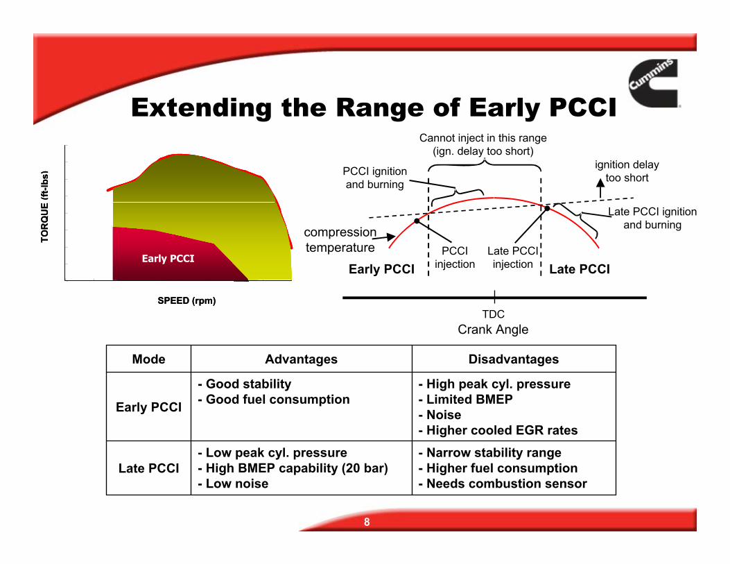
Extending the Range of Early PCCI Cannot inject in this range
(ign. delay too short) ignition delay
Late PCCI ignition and burningcompression
temperature
PCCI ignition and burning too short
PCCI Late PCCI injection injectionEarly PCCI Late PCCI
SPEEDSPE (rpm)ED (rpm)TDC
Crank Angle
Mode Advantages Disadvantages
Early PCCI
- Good stability - Good fuel consumption
- High peak cyl. pressure - Limited BMEP - Noise - Higher cooled EGR rates
Late PCCI - Low peak cyl. pressure - High BMEP capability (20 bar) - Low noise
- Narrow stability range - Higher fuel consumption - Needs combustion sensor
8
9
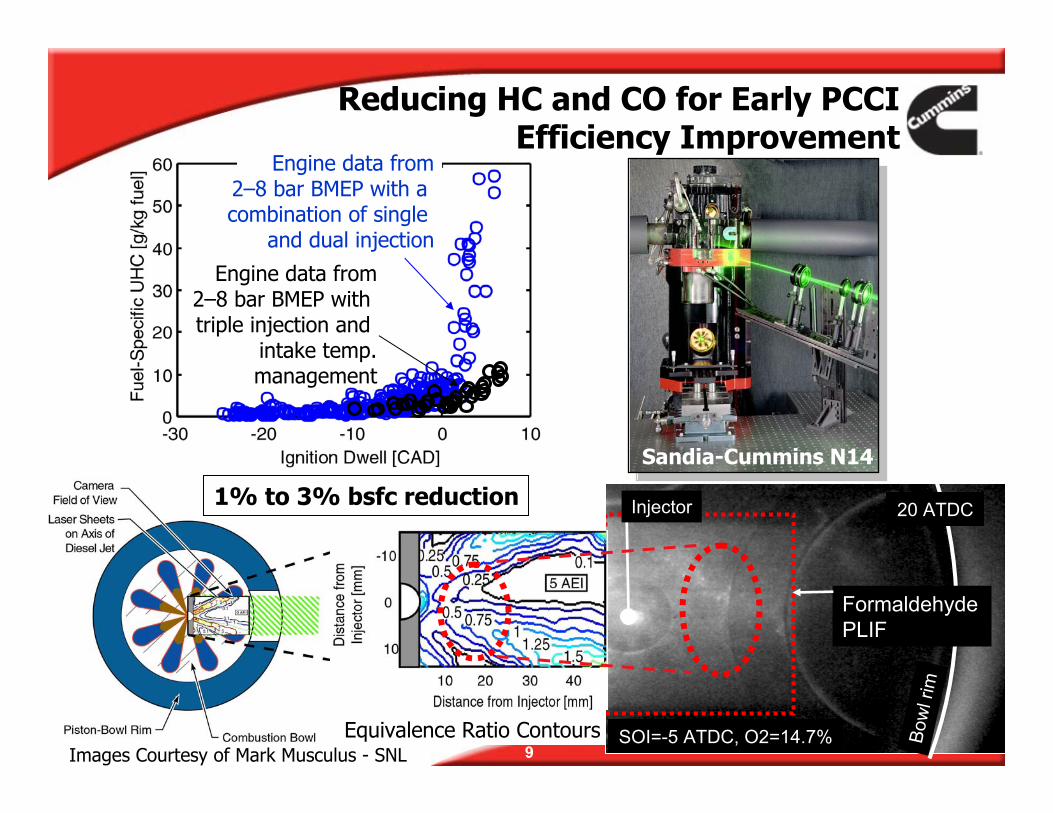
Bow
l rim
Formaldehyde PLIF
SOI=-5 ATDC, O2=14.7%
20 ATDCInjector
Equivalence Ratio Contours
1% to 3% bsfc reduction
Sandia-Cummins N14
Images Courtesy of Mark Musculus - SNL
Engine data from 2–8 bar BMEP with triple injection and
intake temp. management
Engine data from 2–8 bar BMEP with a combination of single
and dual injection
Reducing HC and CO for Early PCCI Efficiency Improvement
ISX Technology Roadmapfor Efficiency Improvement
EGR Loop
Fuel System Advanced LTC
Controls
Variable Valve
Actuation
Variable Intake Swirl
Turbo Technology
Electrically Driven Components
Aftertreatment
10
0
0.1
0.2
0.3
0.4
0 5 10 15 20
% Mass Flow
Smok
e
% Mass Flow - H
11
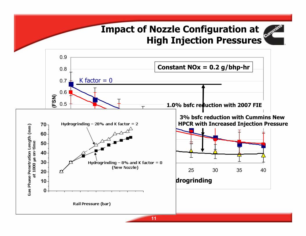
0.5
0.6
0.7
0.8
0.9
25 30 35 40
(FSN
)
Constant NOx = 0.2 g/bhp-hr
ydrogrinding
K factor = 0
1.0% bsfc reduction with 2007 FIE
3% bsfc reduction with Cummins New HPCR with Increased Injection Pressure
Impact of Nozzle Configuration at High Injection Pressures
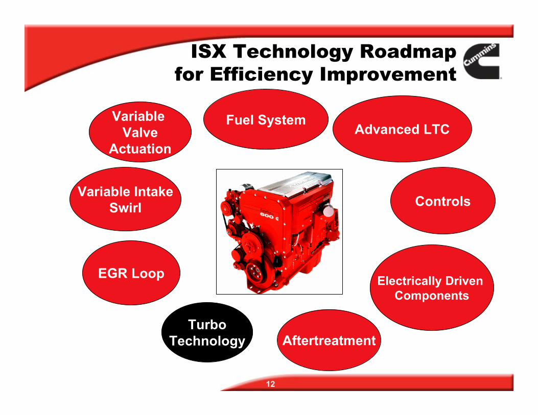
ISX Technology Roadmapfor Efficiency Improvement
EGR Loop
Fuel System Advanced LTC
Controls
Variable Valve
Actuation
Variable Intake Swirl
Turbo Technology
Electrically Driven Components
Aftertreatment
12
13
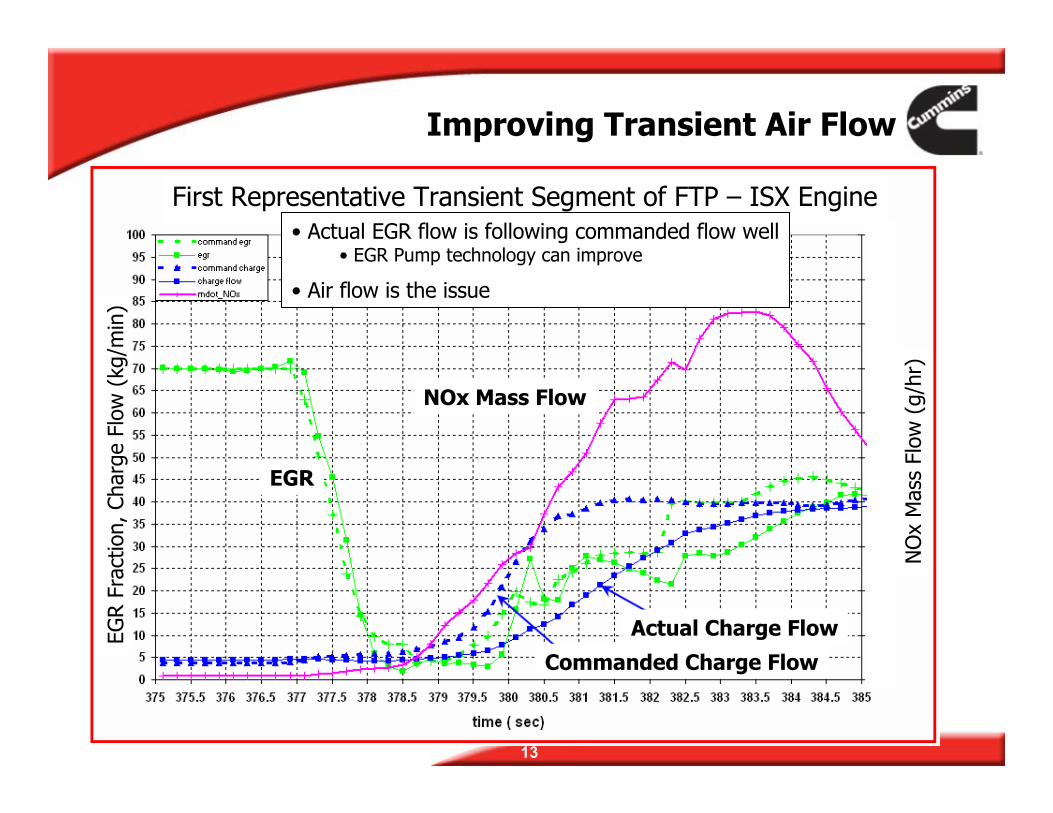
Improving Transient Air Flow
First Representative Transient Segment of FTP – ISX Engine
NO
x M
ass
Flow
(g/
hr)
EGR F
ract
ion,
Cha
rge
Flow
(kg
/min
)
EGR
NOx Mass Flow
Actual Charge Flow
Commanded Charge Flow
• Actual EGR flow is following commanded flow well • EGR Pump technology can improve
• Air flow is the issue
14
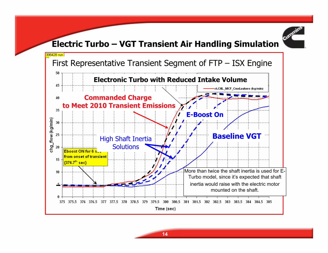
Commanded Charge to Meet 2010 Transient Emissions
E-Boost On
High Shaft Inertia Solutions
First Representative Transient Segment of FTP – ISX Engine
Electric Turbo – VGT Transient Air Handling Simulation
Electronic Turbo with Reduced Intake Volume
More than twice the shaft inertia is used for E-Turbo model, since it’s expected that shaft inertia would raise with the electric motor
mounted on the shaft.
Baseline VGT
ISX Technology Roadmapfor Efficiency Improvement
EGR Loop
Fuel System Advanced LTC
Controls
Variable Valve
Actuation
Variable Intake Swirl
Turbo Technology
Electrically Driven Components
Aftertreatment
15
6.5 7
7.5
8.5
9
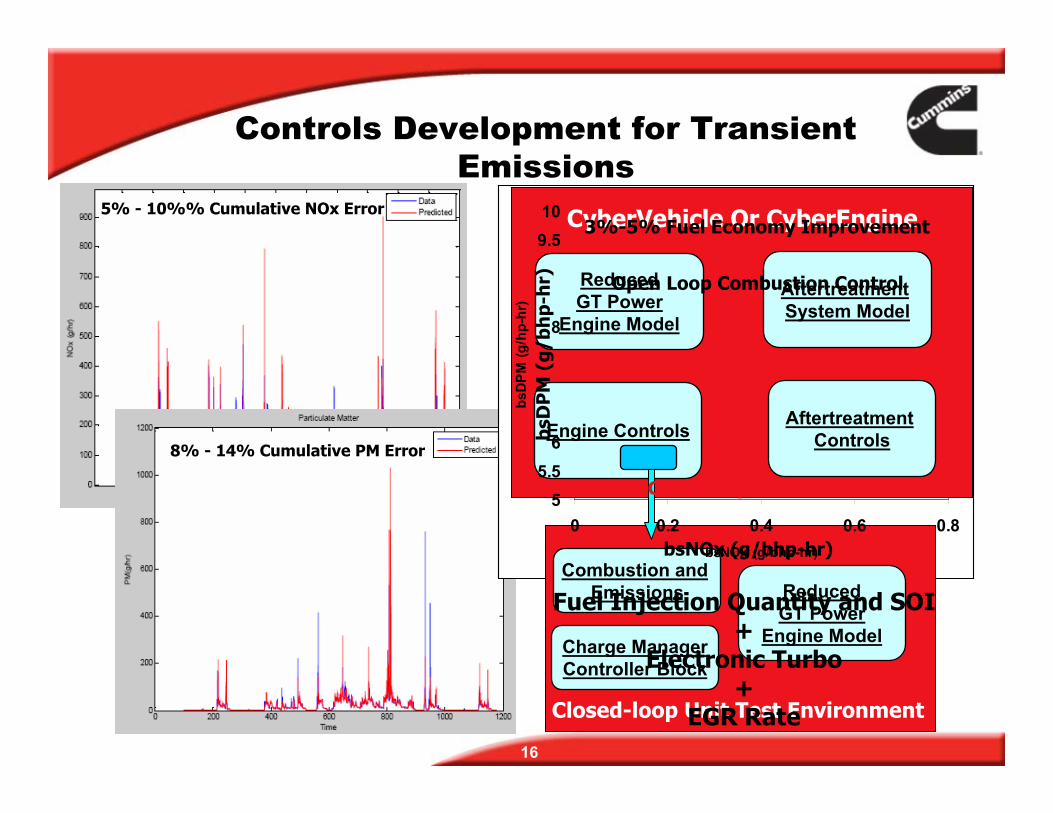
Controls Development for Transient Emissions
5% - 10%% Cumulative NOx Error 10 CyberVehicle Or CyberEngine3%-5% Fuel Economy Improvement 9.5
bsD
PM (g
/hp-
hr)
bsD
PM
(g/
bhp-
hr)
GT Power ReducedOpen Loop Combustion ControlAftertreatment
8Engine Model System Model
Engine Controls8% - 14% Cumulative PM Error 6
5.5
Aftertreatment Controls
Close Loop Combustion Control 5 0 0.2 0.4 0.6 0.8
bsNOx (g/bhp-hr) bsNOx (g/bhp-hr) Combustion and
Emissions ReducedFuel Injection Quantity and SOIGT Power + Engine ModelCharge ManagerElectronic TurboController Block +
Closed-loop Unit Test EnvironmentEGR Rate 16
60
Bra
ke T
herm
al E
ffici
ency
(%)
55
50
45
40
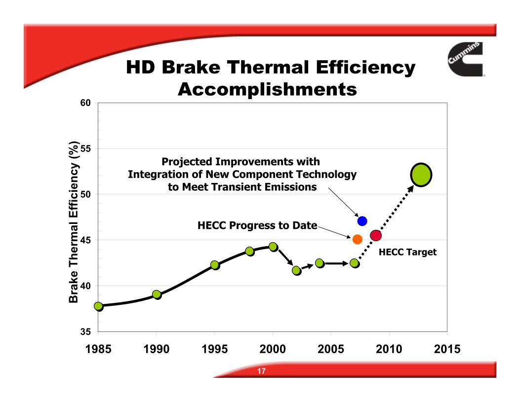
HD Brake Thermal Efficiency Accomplishments
HECC Progress to Date
Projected Improvements with Integration of New Component Technology
to Meet Transient Emissions
HECC Target
1985 1990 1995 2000 2005 2010 2015
17
35


![Nuirooefenen vgt[1]](https://img.pdfslide.net/doc/110x75/556372cad8b42ae6088b55bd/nuirooefenen-vgt1.jpg)