Embed Size (px)
Citation preview
RM A5lE04
NACA
RESEARCH MEMORANDUM
EXPERWENTAL STUDY OF THE EFFECT OF SWEEPBACK ON
TRANSONIC AILERON FLUTTER
By Lionel L. Levy, Jr., and Earl D. Knechtel
Ames Aeronautical Laboratory Moffett Field, Calif.
NATIONAL ADVISORY COMMITTEE FOR AERONAUTICS
W A SHI NGTON September 10, 1951
to.·
I ,
https://ntrs.nasa.gov/search.jsp?R=19930086668 2018-07-07T23:53:38+00:00Z

1 NACA RM A5lE04
NATIONAL ADVISORY COMMITTEE FOR AERONAUTICS
RESEARCH MEMORANDUM
EXPERIMENTAL STUDY OF THE EFFECT OF SWEEPBACK ON
TRANSONIC AILERON FLUTTER
By Lionel L. Levy, Jr., and Earl D. Knechtel
SUMMARY
The effects of sweepback on the occurrence and principal characteristics of single-degree-of-freedom aileron flutter have been determined for a wing-aileron combination comprising an NACA 65-213, a = 0.5, airfoil section normal to the quarter-chord line, and a 25-percent-chord aileron extending over the outer 50 percent of the wing span for 00 ,
20°, 300, 40°, and 500 angles of sweep. The Mach number range of the
investigation extended from 0.70 to 0.95 approximately; Reynolds numbers varied from 0.7 X 10⁶ to 1.1 X 10 6
• Angles of attack were varied from _60 to +60 •
Aileron flutter was encountered at all angles of sweep. The Mach number of incipient flutter was found to increase as the amount of sweepback increased, and, for all angles of sweep, to decrease as the angle of attack increased. For constant angle of attack of the model the frequency of flutter increased slightly up to a sweep angle of 20b, but decreased thereafter with further increases in sweep.
INTRODUCTION
During the flight tests (reference 1) of a straight-wing, jetpowered, fighter airplane, a high-frequency, low-amplitude aileron flutter commencing in the neighborhood of 0.8 Mach number was encountered. Further investigation of the phenomenon disclosed the fact thet at higher Mach numbers the amplitude of the flutter increased markedlY. In fact, during one test flight the motion was so severe as to result in permanent deformation of the aileron.
Because of the hazard accompanying further investigations of this flutter in flight, a full-scale partial-span production wing was tested
------._- --~-~--~~----~-----"
2 NACA RM A5lE04
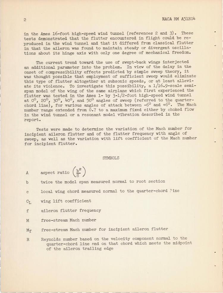
in the Ames l6-foot high-speed wind tunnel (references 2 and 3). These tests demonstrated that the flutter encountered in flight could be reproduced in the wind tunnel and that it differed from classical flutter in that the aileron was found to maintain steady or divergent oscillations about its hinge axis with only one degree of mechanical freedom.
The current trend toward the use of swept-back wings interjected an additional parameter into the problem. In view of the delay in the onset of compressibility effects predicted by simple sweep theory, it was thought possible that employment of sufficient sweep would eliminate this type of flutter altogether at subsonic speeds, or at least alleviate its violence. To investigate this possibility, a 1/16.9-scale semispan model of the wing of the same airplane which first experienced the flutter was tested in the Ames 1- by 3-l/2-foot high-speed wind tunnel at 00
, 200, 300
, 400 , and 500 angles of sweep (referred to the quarterchord line), for various angles of attack between _60 and +60 • The Mach number range extended from 0.7 to a maximum fixed either by choked flow in the wind tunnel or a resonant model vibration described in the report.
Tests were made to determine the variation of the Mach number for incipient aileron flutter and of the flutter frequency with angle of sweep, as well as the variation with lift coefficient of the Mach number for incipient flutter.
SYMBOLS
A aspect ratio (~2) b twice the model span measured normal to root section
c local wing chord measured normal to the quarter-chord :ine
CL wing lift coefficient
f aileron flutter frequency
M free-stream Mach number
Mf free-stream Mach number for incipient aileron flutter
R Reynolds number based on the velocity component normal to the quarter-chord line and on that chord which meets the midpoint of the aileron trailing edge
'--------~~~-~-~~- -----~~-.~-----------~~--
NACA RM A5lE04 3
S twice the area of semispan model
~ model angle of attack, degrees
~ angle of attack in a plane normal to the quarter-chord line, degrees
o total aileron motion, degrees
A angle of sweep of the quarter-chord line, degrees
APP MATUS AND MODEL
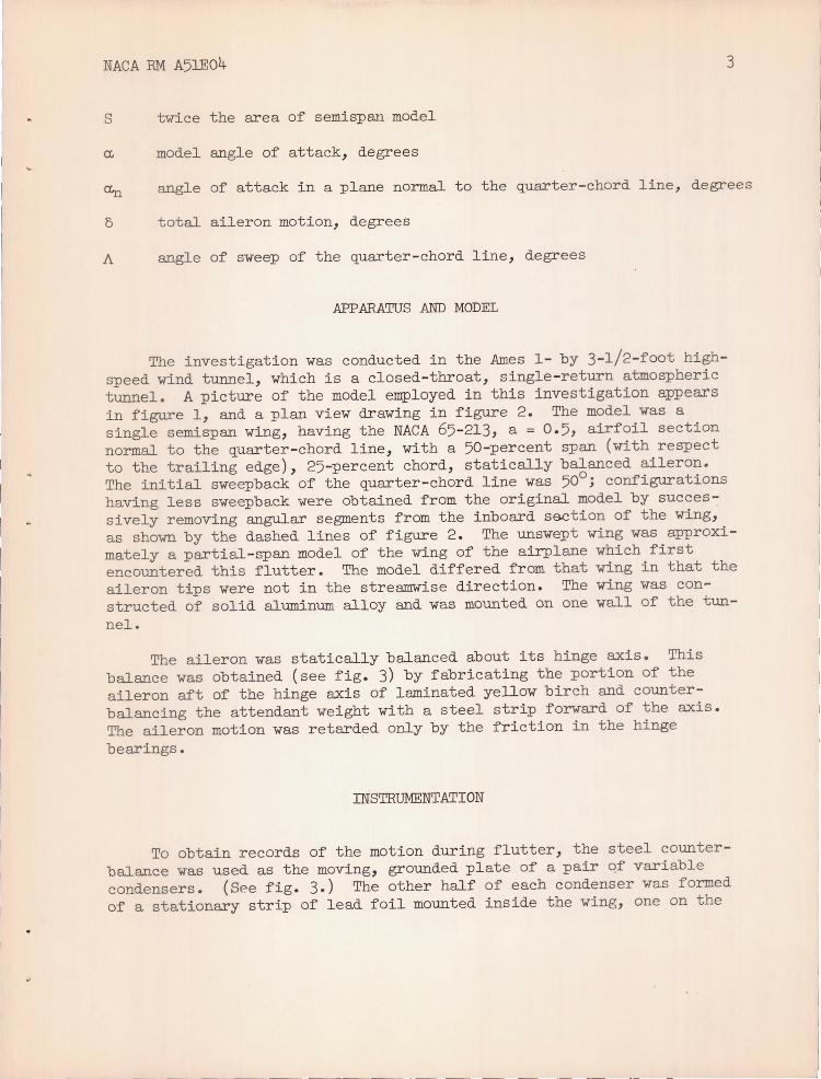
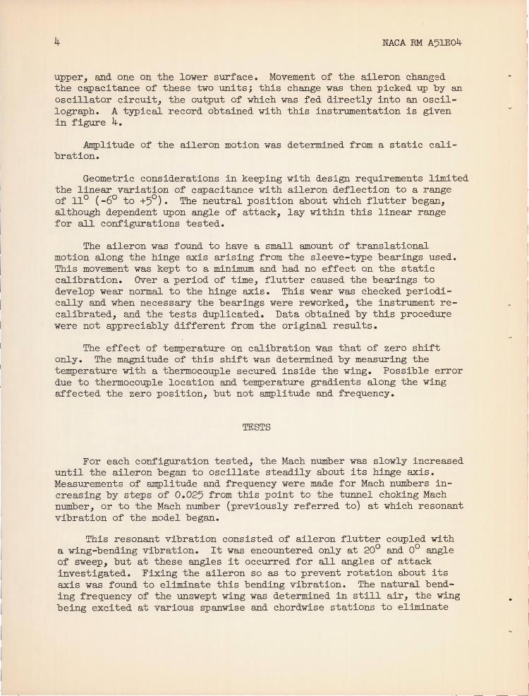
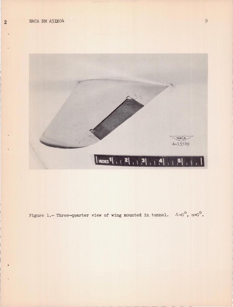
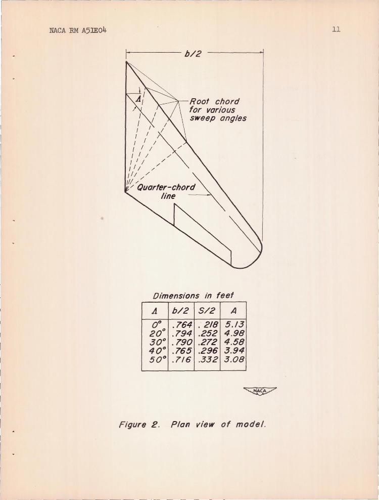
The investigation was conducted in the Ames 1- by 3-1!2-foot highspeed wind tunnel, which is a closed-throat, single-return atmospheric tunnel. A picture of the model employed in this investigation appears in figure 1, and a plan view drawing in figure 2. The model was a single semispan wing, having the NACA 65-213, a = 0.5, airfoil section normal to the quarter -chord line, with a 50-percent span (with respect to the trailing edge), 25-percent chord, statically balanced aileron. The initial sweepback of the quarter-chord line was 500
; configurations having less sweepback were obtained from the original model by successively removing angular segments from the inboard section of the wing, as shown by the dashed lines of figure 2. The unswept wing was approximately a partial- span model of the wing of the airplane which first encountered this flutter. The model differed from that wing in that the aileron tips were not in the streamwise direction. The wing was constructed of solid aluminum alloy and was mounted on one wall of the tunnel.
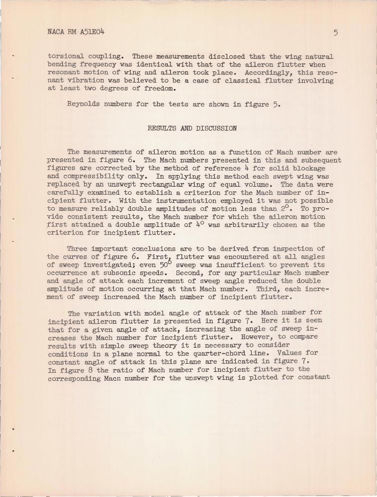
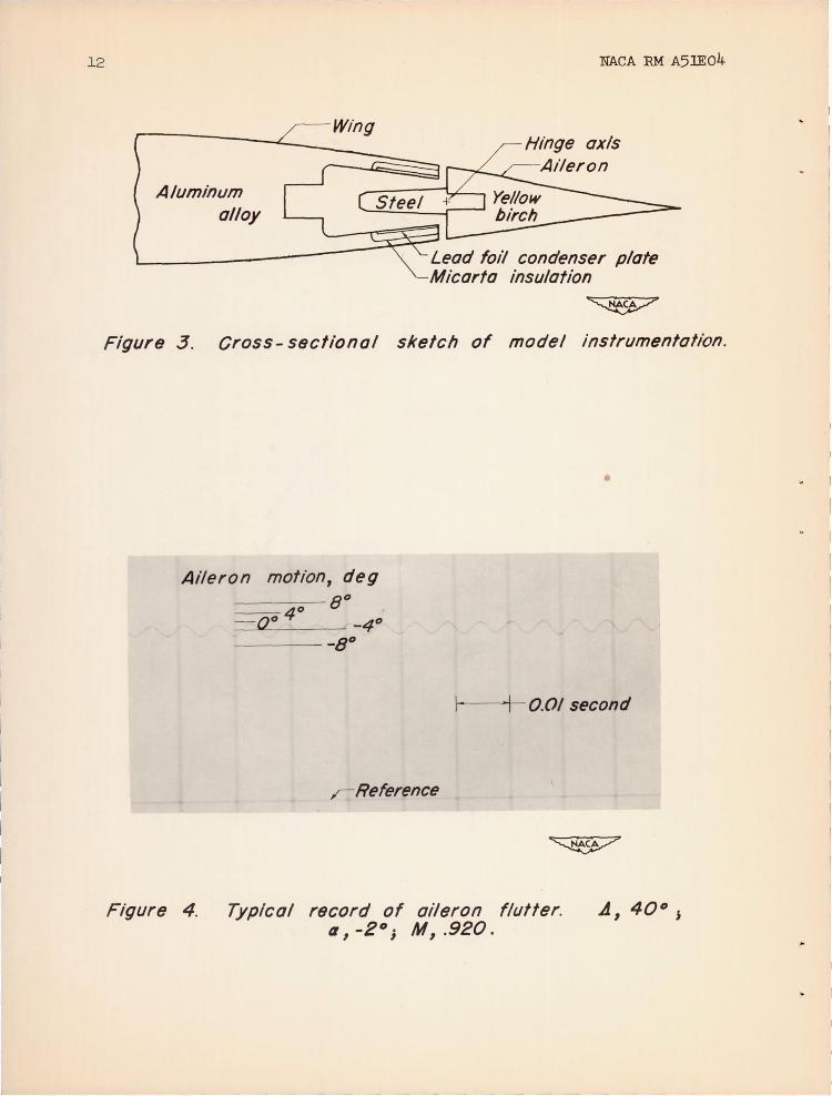
The aileron was statically balanced about its hinge axis. This balance was obtained (see fig. 3) by fabricating the portion of the aileron aft of the hinge axis of laminated yellow birch and counterbalancing the attendant weight with a steel strip forward of the axis. The aileron motion was retarded only by the friction in the hinge bearings.
INSTRUMENTATION
To obtain records of the motion during flutter, the steel counterbalance was used as the mOVing, grounded plate of a pair qf variable condensers. (See fig. 3.) The other half of each condenser was formed of a stationary strip of lead foil mounted inside the wing, one on the
--~---~~----~-~ -- ---~-- ~-~--~--~----~-~ ___ _ _ ___ _ ~_~--.J
4 NACA RM A5lEo4
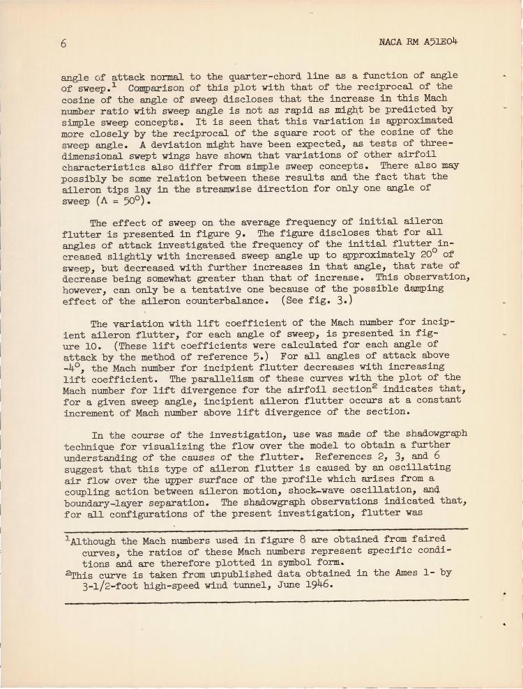
upper, and one on the lower surface. Movement of the aileron changed the capacitance of these two units; this change was then picked up by an oscillator circuit, the output of which was fed directly into an oscillograph. A typical record obtained with this instrumentation is given in figure 4.
Amplitude of the aileron motion was determined from a static calibration.
Geometric considerations in keeping with design requirements limited the linear variation of capacitance with aileron deflection to a range of 110 (_60 to +50
). The neutral position about which flutter began, although dependent upon angle of attack, lay within this linear range for all configurations tested.
The aileron was found to have a small amount of translational motion along the hinge axis arising from the sleeve-type bearings used. This movement was kept to a minimum and had no effect on the static calibration. Over a period of time, flutter caused the bearings to develop wear normal to the hinge axis. This wear was checked periodically and when necessary the bearings were reworked, the instrument recalibrated, and the tests duplicated. Data obtained by this proced~e were not appreciably different from the original results.
The effect of temperature on calibration was that of zero shift only. The magnitude of this shift was determined by measuring the temperature with a thermocouple secured inside the wing. Possible error due to thermocouple location and temperature gradients along the wing affected the zero position, but not amplitude and frequency.
TESTS
For each configuration tested, the Mach number was slowly increased until the aileron began to oscillate steadily about its hinge axis. Measurements of amplitude and frequency were made for Mach numbers increasing by steps of 0.025 from this point to the tunnel choking Mach number, or to the Mach number (previously referred to) at which resonant vibration of the model began.
This resonant vibration consisted of aileron flutter coupled with a wing-bending vibration. It was encountered only at 200 and 00 angle of sweep, but at these angles it occurred for all angles of attack investigated. Fixing the aileron so as to prevent rotation about its axis was found to eliminate this bending vibration. The natural bending frequency of the unswept wing was determined in still air, the wing being excited at various spanwise and chordwise stations to eliminate
.--~- .--- ~~.
NACA RM A5lE04 5
torsional coupling. These measurements disclosed that the wing natural bending frequency was identical with that of the aileron flutter when resonant motion of wing and aileron took place. Accordingly, this resonant vibration was believed to be a case of classical flutter involving at least two degrees of freedom.
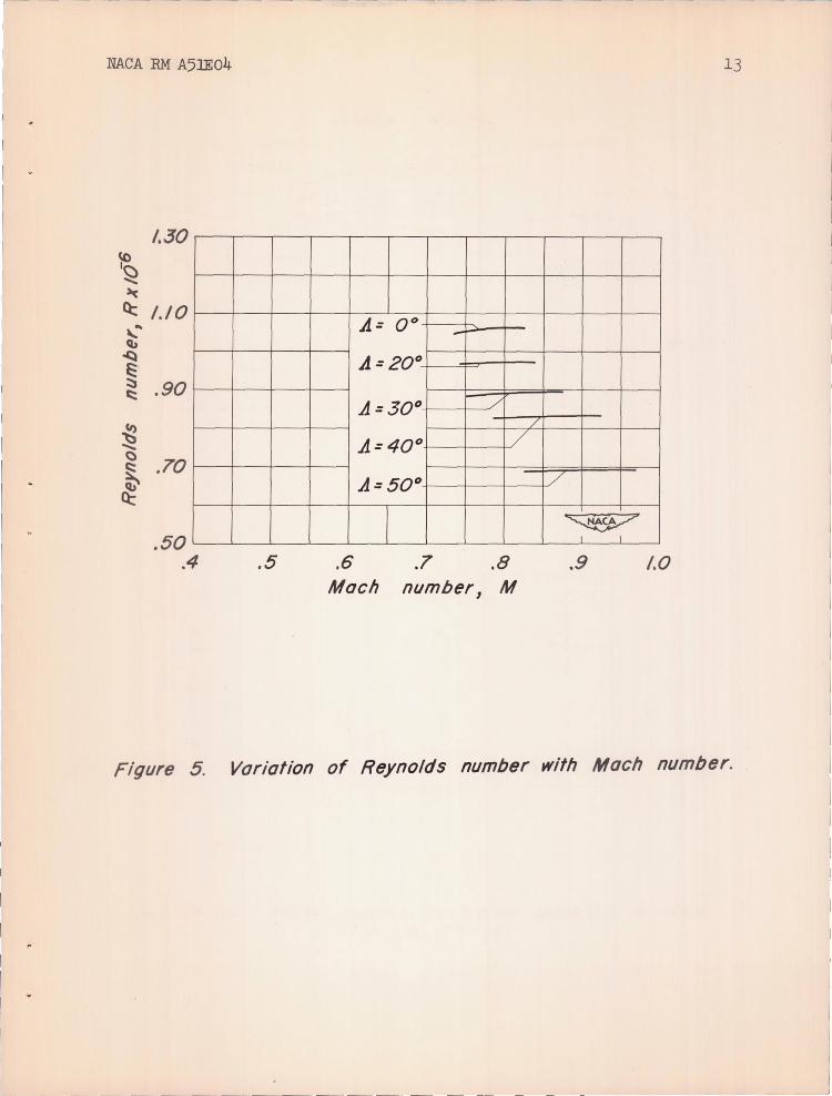
Reynolds numbers for the tests are shown in figure 5.
RESULTS AND DISCUSSION
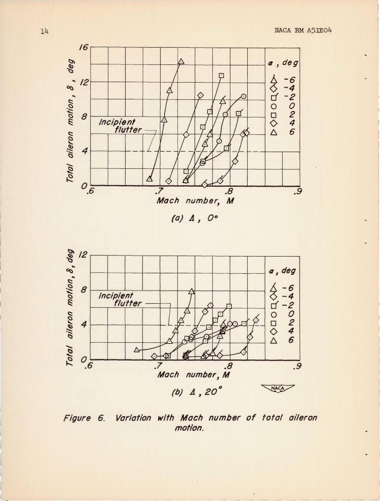
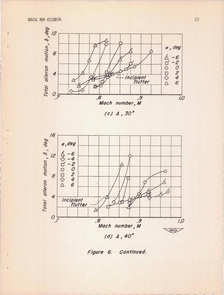
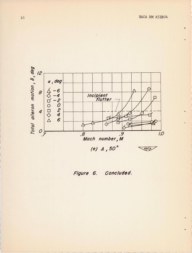
The measurements of aileron motion as a function of Mach number are presented in figure 6. The Mach numbers presented in this and subsequent figures are corrected by the method of reference 4 for solid blockage and compressibility only. In applying this method each swept wing was replaced by an unswep't rectangular wing of equal volume. The data were carefully examined to establish a criterion for the Mach number of incipient flutter. With the instrumentation employed it was not possible to measure reliably double amplitudes of motion less than 20. To provide consistent results, the Mach number for which the aileron motion first attained a double amplitude of 40 was arbitrarily chosen as the criterion for incipient flutter.
Three important conclusions are to be derived from inspection of the curves of figure 6. First flutter was encountered at all angles of sweep investigated; even 506 sweep was insufficient to prevent its occurrence at subsonic speeds. Second, for any particular Mach number and angle of attack each increment of sweep angle reduced the double amplitude of motion occurring at that Mach number. Third, each increment of sweep increased the Mach number of incipient flutter.
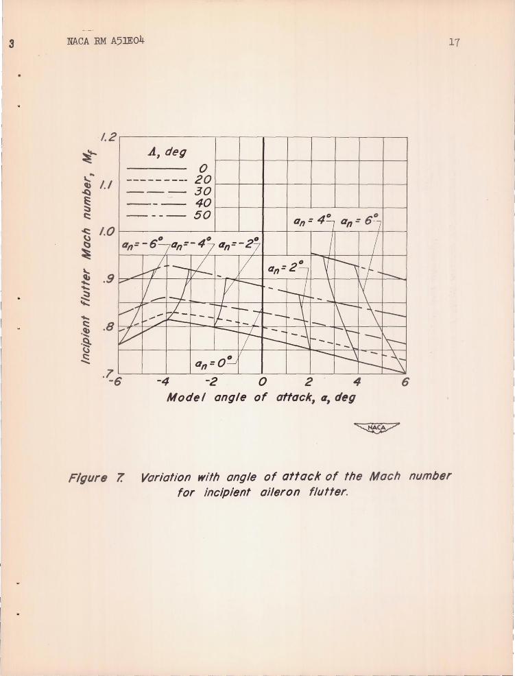
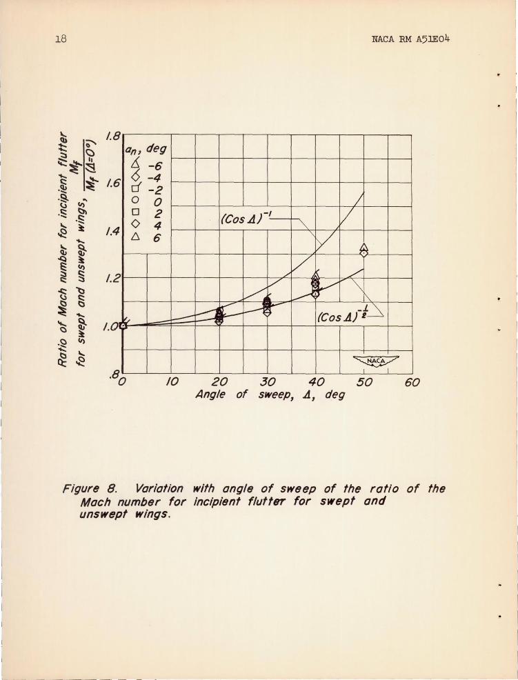
The variation with model angle of attack of the Mach number for incipient aileron flutter is presented in figure 7. Here it is seen that for a given angle of attack, increasing the angle of sweep increases the Mach number for incipient flutter. However, to compare results with simple sweep theory it is necessary to consider conditions in a plane normal to the quarter-chord line. Values for constant angle of attack in this plane are indicated in figure 7. In figure 8 the ratio of Mach number for incipient flutter to the corresponding Macn number for the unswept wing is plotted for constant
6 NACA RM A5lED4
angle clf attack normal to the quarter-chord line as a fUnction of angle of sweep.1 Comparison of this plot with that of the reciprocal of the cosine of the angle of sweep discloses that the increase in this Mach number ratio with sweep angle is not as rapid as mi~t be predicted by simple sweep concepts. It is seen that this variation is approximated more closely by the reciprocal of the square root of the cosine of the sweep angle. A deviation might have been expected, as tests of threedimensional swept wings have shown that variations of other airfoil characteristics also differ from Simple sweep concepts. There also may possibly be some relation between these results and the fact that the aileron tips lay in the streamwise direction for only one angle of sweep (A = 5(0 ).
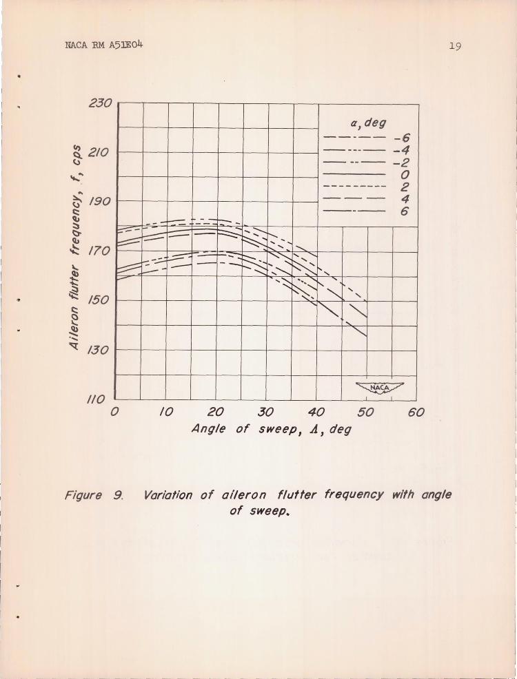
The effect of sweep on the average frequency of initial aileron flutter is presented in figure 9. The figure discloses that for all angles of attack investigated the frequency of the initial flutter increased slightly with increased sweep angle up to approximately 200 of sweep, but decreased with further increases in that angle, that rate of decrease being somewhat greater than that of increase. This observation, however, can only be a tentative one because of the possible damping effect of the aileron counterbalance. (See fig. 3.)
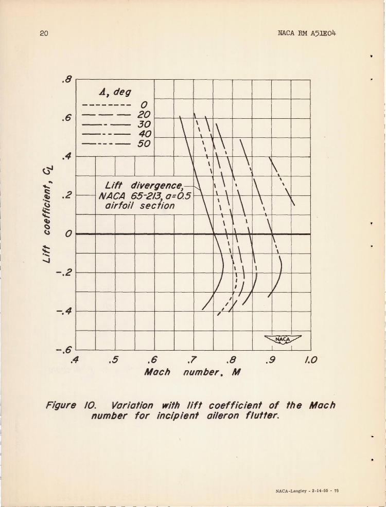
The variation with lift coefficient of the Mach number for incipient aileron flutter, for each angle of sweep, is presented in fig-ure 10. (These lift coefficients were calculated for each angle of attack by the method of reference 5.) For all angles of attack above _40
, the Mach number for incipient flutter decreases with increasing lift coefficient. The parallelism of these curves with the plot of the Mach number for lift divergence for the airfoil section2 indicates that, for a given sweep angle, incipient aileron flutter occurs at a constant increment of Mach number above lift divergence of the section.
In the course of the investigation, use was made of the shadowgraph technique for visualizing the flow over the model to obtain a further understanding of the causes of the flutter. References 2, 3, and 6 suggest that this type of aileron flutter is caused by an oscillating air flow over the upper surface of the profile which arises from a coupling action between aileron motion, shock-wave oscillation, an~ boundary-layer separation. The shadowgraph observations indicated that, for all configurations of the present investigation, flutter was
lAlthough the Mach numbers used in figure 8 are obtained from faired curves, the ratios of these Mach numbers represent specific conditions and are therefore plotted in symbol form.
~is curve is taken from unpublished data obtained in the Ames 1- by 3-l/2-foot high-speed wind tunnel, June 1946.
- ~- - -- ------~
-~.~----~-~~~-----~------~-
NACA RM A51E04
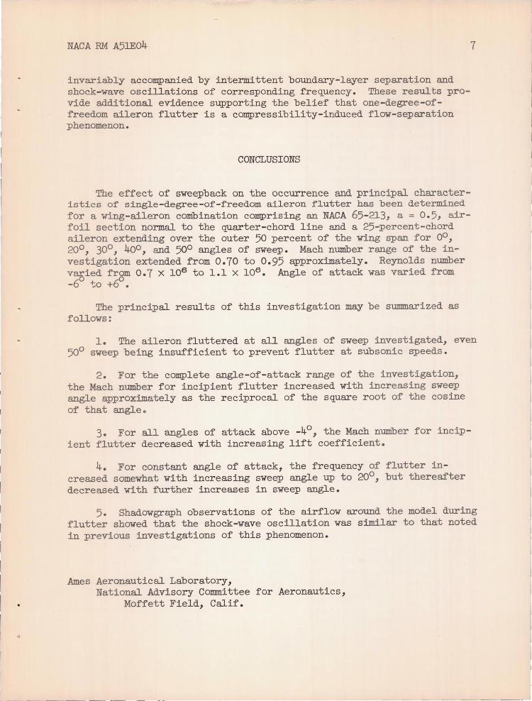
invariably accompanied by intermittent boundary-layer separation and shock-wave oscillations of corresponding frequency. These results provide additional evidence supporting the belief that one-degree-offreedom aileron flutter is a compressibility-induced flow-separation phenomenon.
CONCLUSIONS
The effect of sweepback on the occurrence and principal characteristics of single-degree-of-freedom aileron flutter has been determined for a wing-aileron combination comprising an NACA 65-213, a = 0.5, airfoil section normal to the quarter-chord line and a 25-percent-chord aileron extending over the outer 50 percent of the wing span for 00 ,
200 , 300 , 400 , and 500 angles of sweep. Mach number range of the investigation extended from 0.70 to 0.95 approximately. Reynolds number v~ied from 0.7 X 10⁶ to 1.1 X 10⁶ • Angle of attack was varied from -6 to +~.
The principal results of this investigation may be summarized as follows:
7
1. The aileron fluttered at all angles of sweep investigated, even 500 sweep being insufficient to prevent flutter at subsonic speeds.
2. For the complete angle-of-attack range of the investigation, the Mach number for incipient flutter increased with increasing sweep angle approximately as the reciprocal of the square root of the cosine of that angle.
3. For all angles of attack above _40, the Mach number for incip
ient flutter decreased with increaSing lift coefficient.
4. For constant angle of attack, the frequency of flutter increased somewhat with increasing sweep angle up to 200 , but thereafter decreased with further increases in sweep angle.
5. Shadowgraph observations of the airflow around the model during flutter showed that the shock-wave oscillation was similar to that noted in previous investigations of this phenomenon.
Ames Aeronautical Laboratory, National Advisory Committee for Aeronautics,
Moffett Field, Calif.
8 NACA RM A5lE04
REFERENCES
1 . Brown, Harvey H., Rathert, George A., Jr., and Clousing, Lawrence A.: Flight-Test Measurements of Aileron Control Surface Behavior at Supercritical Mach Numbers. NACA RM A7Al5, 1947.
2 . Erickson, Albert L., and Stephenson, Jack D.: A Suggested Met hod of Analyzing for Transonic Flutter of Control Surfaces Based on Available Experimental Evidence. NACA RM A7F30, 1947.
3. Erickson, Albert L., and Mannes, Robert L.: Wind-Tunnel Investigation of Transonic Aileron Flutter. NACA RM A9B28, 1949.
4. Herriot, John G.: Blockage Corrections for Three-Dimensional-Flow Closed-Throat Wind Tunnels, with Consideration of the Effect of Compressibility. NACA Rep. 995, 1950. (Formerly NACA RM A7B28)
5. DeYoung, John: Theoretical Additional Span Loading Characteristics of Wings with Arbitrary Sweep , Aspect Ratio and Taper Ratio. NACA Rep. 921, 1949. (Formerly NACA TN's 1491, 1772, and 1476)
6 . Phillips, William H., and Adams, James J.: Low-Speed Tests of a Model Simulating the Phenomenon of Control-Surface Buzz. MCA RM L50F19, 1950.
2 NAeA EM A5lEo4 9
~ A-15589
\ \IDU '\ , r 2\ , \ ~\ , \ ~\ , , ,'I I , I ,
Figure 1.- Tbree-quarter vi ew of wing mounted in tunnel. o 0 A=O , 0,=0 •

1------ b/2 ----~
Root chord for various sweep angles
Dimensions in feet
A b/2 S/2 A
0° .764.' 218 5.13 20° .794 .252 4.98 30° .790 .272 4.58 40° .765 .296 3.94 50° .716 .332 3.08
Figure 2. Plan view of model.
--~----'- -~~---
11
l2
r---______ ~ __ ~w. .. mg
Aluminum alloy
NACA EM A5lE04
Hinge axis Aileron
L ___ -------~~Lead foil condenser plate Micarta insulation
~
Figure 3. Cross- sectional sketch of model instrumentation .
Aileron motion, deg ____ 8° ~---"L-O_o_4_0 __ -40 ____ _ 8°
•
1--->+1- 0 .01 second
Figure 4.
,r-Reference
Typical record of aileron flutter. a 1 _20 j M" 920 .
NAeA RM A51E04
1.30
~ -<:)
~ .70
~
.50 .4 .5
13
.A,: 0"
.A,:20"
A:: 30° ./
/
A::40° /
A:50° /
I ~ I I
.6 .7 .8 .9 1.0 Mach number 1 M
Figure 5. Var iation of Reynolds number with Mach number.
14 NAeA EM A5lEo4
16
~
~ .. 12 ~
(I , deg
~ -6 -4 ..
t:: .<::) ~
8 <::)
Incipient ~
t:: flutter
cf -2 0 0 0 2 0 4 6 6
~ ~ .~ 4
-~ ~
0.6 .8 number, M
.9
(a) .A, 0°
~ ~ 12
r--+--~--~-+--~--+--4--~--+-~Q,deg .. ~ ..
r--L~L--L--+--+~~~--~~--~ ~ =~ rf -2
t:: .<::) 8 .;::
Incipient <::)
~ flutter o 0 o 2 o 4
r--r--r--+--~~~~U4~4-~~~ 6 6
t:: ~ 4 ~
" t) -~
~6 ~ .7 .8 .9 Mach number I M
(b) .A I 20°
Figure 6. Variation with Mach number of fotal aileron motion.
NAeA RM A5JEo4
~
~ 12r--'--.--.--~~--~--~~--~~----~ ... c.a
... c::: a,deg ~ 8r--r--+--++-~~r+~~~-+~~~ o 6. -6 E: d-2
o 0 -'------l_~ 0 2 o 4 -~ r--r--~~-=4R~~~--~~~~~~ 6
~ 0.7~~~~~--~~--~--~~--~~----~ .8 .9 1.0
/6 ~
~ ...
c.a 12 ...
Moch number, M
(c) .A I 30(1
a, deg
~ -6 -4
rf -2 18 / 0 0 / / 0 2 0 4 j II ( 6 6 •
/ Y I- Ji ~ Incipient v: tt .fW ' ~
flutter ~ ;:OW I t! '-i
.8 .9 Moch nlJmber, M
(d) .A 40(1 ,
FiglJre 6. Continued.
~ .....Q
A ./
/ ~I ..--=-
1.0
~
15
______ _ ___ _ , __ __ ~~~ ____ ~_._l
~ - - --~.~~-=~----------~---------~
16 NAeA EM A5JEo4
b. ~ 12~----~--~~--~~--~--~~~~--~~
.8 .9 1.0 Moch number I M
(e) .A I 50 o
Figure 6. Concluded.
. I
3 NAeA RM A5lEo4 17
1.2
~'t.... .A, deg
0 .. "'" 1,/ Cb ~
--------- 20 - -- 30
§ c:
-c:: 1.0 u C::»
~
"'" Cb .9 '" '" ~ , '" c: .8 .~ .9-~
~
----- 40 - --- 50 4D D an = .- an = 6 -7
D D D I / an= - 6 an=-47 an=-27
~ ---. l- II an=2~ V ~ ~J ~ -- I ~ --i--"" / IJ Y I--- r-J \ ~ ----vI 1-- ........ ri- 1--_ [t--r:7 1---, 1\-~\ r---
./ -+-- ~ 1-
~ V -----~
-~ - -\ ~~ r-- 1- __ --I\-r-- --~ -~ D an=O~ r---
-4 o 2 ' 4 6 Model angle of attock, a, deg
Figure 7. Variation with angle of attack of the Mach number for incipient aileron flutter.
18 NACA RM A5lE04
an, deg ~ -6 <$ -4 d -2
I 0 0 0 2 (Cos .L1)-1 [7 0 4 '" 6, 6 '\ Y ~~
/ V /'"
Y. V U .V "" I\. ~ r- H r- -G
II'" ~ (Cos.L1) I - ,
~ I I
m 20 ~ 40 50 60 Angle of sweep, .A, deg
F igure 8. Variation with angle of sweep of the ratio of the Mach number for incipient flutter for swept and unswept wings.
MACA EM A5JE04 19
230
CI) 210 ~
....... .. ~ 190 c:: ~ ~ ~ <U ~ 170
~-
~
\.,
~ ~ 150
:::::::::: -c:: ~ ~ ..... ~ 130
110 o
Figure 9.
a,deg ----- -6 - ------ -4 ---- -2
0 - - ------- 2 - -- 4
--- 6 -- -I-- - -:: r:-- _
I-' ..... :---- ...... :-...... ~ - - --~ .......... ,
...:::. ........ .......
-::: -..::.- :.:;::- -, ~ ........ ~
.... "-- ~ L..--- - - --f..........:::: -:.............: " .... '~ ~~ r--- "
""'-,
.......... , ... ......
" 1"'- "-., ""'-
~ I I
10 20 30 40 50 60 Angle of sweep 1 A, deg
Variation of aileron flLlfter frequency with angle of sweep_
20 NACA EM A51E04
~ .. ...... c::
:~ ~ q" () ()
~ ..... ....J
.8
.6
.4
.2
0
- .2
-.4
-.6 .4
A, deg ------ -- 0 --- 20 --- 30 \ \\ :\ ---- 40 - ---- 50 \ \ ~ \ \ \
, \ . \
I , \ \ \ \
I ~ \ \ \
~ \ \ ~ 1\ Lift divergence,- , NACA 65-213, 0=05 \ \ \
\ \ \ \ \ airfoil sec l ion \ \
\ , \ \
\ \ \
~\ \ , , ,\ \
I) J ; )
/ , y'l ,/)
7
.5 .6 .7 .8 Mach number. M
~ \
\
\
\ j\
\ ~ \
) V
I
~ I I
.9 1.0
Figure 10. Variation with lift coefficient of the Mach number for incipient aileron flutter.
NACA-Langley - 2-14-55 - 75