Embed Size (px)
Citation preview
Residual Strength of Concrete-encased Steel Angle Columns after
Spalling of Cover Concrete
*Chang-Soo Kim1) and Hyeon-Jong Hwang2)
1) School of Civil Engineering, Shandong Jianzhu Univ., Jinan 250101, China
2) College of Civil Engineering, Hunan Univ., Changsha 410082, China
ABSTRACT
In concrete-encased steel angle columns, in which steel angles are placed at four corners and the corner angles are connected by transverse reinforcement, premature spalling of cover concrete may occur due to the shrinkage of concrete and the weakness plane between cover concrete and core concrete that is created by smooth surface of steel angles and dense transverse reinforcement. However, concrete-encased steel angle columns show good load-carrying capacity even after cover-spalling due to the high contribution of steel angles to strength and stiffness and the good confinement effect of steel angles and transverse reinforcement on core concrete. To investigate the residual strength after cover-spalling, a numerical study was performed considering the strain compatibility, confinement effect, local buckling, and cover-spalling. The numerical investigation showed that when the steel contribution is high and the confinement efficiency is high, concrete-encased steel angle columns exhibit relatively large residual strength even after spalling of cover concrete at corners. 1. INTRODUCTION
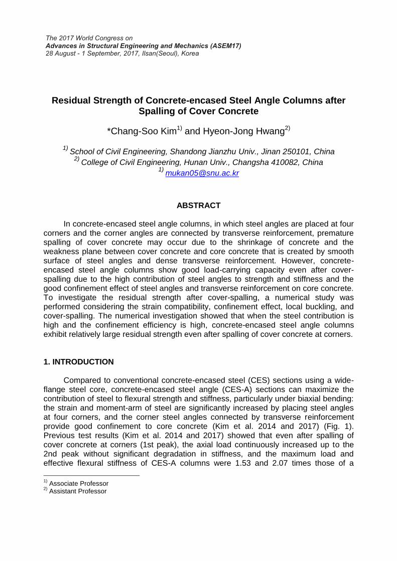
Compared to conventional concrete-encased steel (CES) sections using a wide-flange steel core, concrete-encased steel angle (CES-A) sections can maximize the contribution of steel to flexural strength and stiffness, particularly under biaxial bending: the strain and moment-arm of steel are significantly increased by placing steel angles at four corners, and the corner steel angles connected by transverse reinforcement provide good confinement to core concrete (Kim et al. 2014 and 2017) (Fig. 1). Previous test results (Kim et al. 2014 and 2017) showed that even after spalling of cover concrete at corners (1st peak), the axial load continuously increased up to the 2nd peak without significant degradation in stiffness, and the maximum load and effective flexural stiffness of CES-A columns were 1.53 and 2.07 times those of a
1)
Associate Professor 2)
Assistant Professor
conventional CES column using a wide-flange steel core of the same area, due to the high contribution of steel angles.
Fig. 1 Advantages of CES-A Section
In the present study, to investigate the residual strength of CES-A columns after
cover-spalling, a numerical study was performed by a proposed analysis model. The proposed model considered the strain compatibility, confinement effect, local buckling, and premature cover-spalling. For verification, the predictions by the proposed model were compared with previous test results, and a numerical parametric study was conducted for various design parameters. 2. NUMERICAL MODELING AND VERIFICATION
2.1 Concrete Since the distribution of confining pressure in CES-A sections is similar to that of
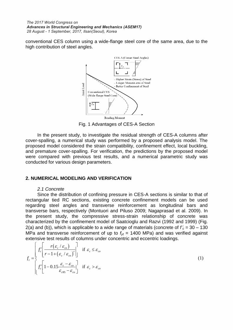
rectangular tied RC sections, existing concrete confinement models can be used regarding steel angles and transverse reinforcement as longitudinal bars and transverse bars, respectively (Montuori and Piluso 2009; Nagaprasad et al. 2009). In the present study, the compressive stress-strain relationship of concrete was characterized by the confinement model of Saatcioglu and Razvi (1992 and 1999) (Fig.
2(a) and (b)), which is applicable to a wide range of materials (concrete of f'c = 30 – 130
MPa and transverse reinforcement of up to fyt = 1400 MPa) and was verified against extensive test results of columns under concentric and eccentric loadings.
85
/if
1 /
1 0.15 if
c co
c c cor
c co
c
c coc c co
c co
rf
rf
f
(1)
Fig. 2 Numerical Modeling for CES-A Section
The definition and calculation of these material properties for concrete modeling
are available in the literatures. To take into account the distinctive local failure mechanisms of CES-A columns in the analysis, the concrete model was modified as follows.
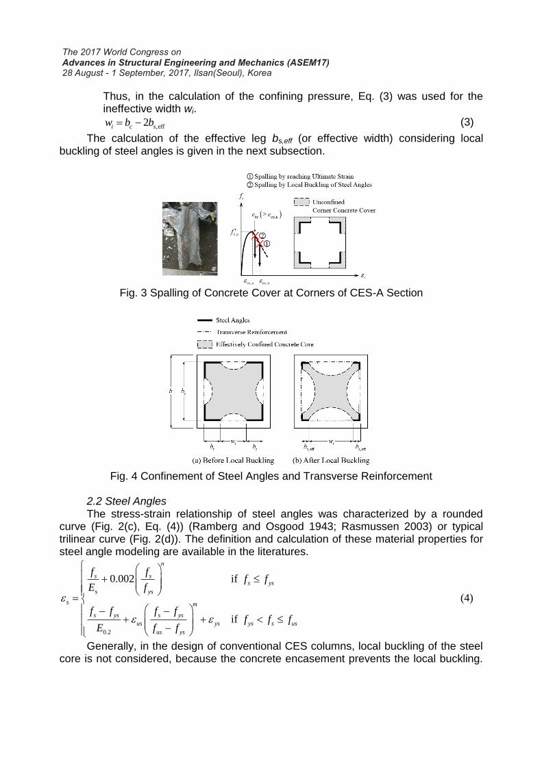
1) Premature cover-spalling may occur due to the shrinkage of concrete and the weakness plane between cover concrete and core concrete that is created by longitudinal and transverse reinforcements, and this phenomenon is more obvious when higher strength concrete and denser reinforcement are used (Collins et al. 1993; Cusson and Paultre 1994). Especially in CES-A columns, the premature cover-spalling is more pronounced at corners due to the smooth surface of steel angles (Kim et al. 2014 and 2017). Thus, for the stress fc,u of cover concrete at corners, the proposed model assumed Eq. (2) (case 1
in Fig. 3). In the absence of experimental data, the ultimate strain of εcu,u =
0.003 is recommended based on test results.
, 0c uf if ,c cu u for cover concrete at corners (2)
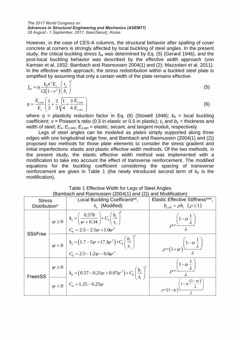
2) Steel angles provide good confinement to core concrete, but the effect of local buckling on the confinement should be also considered. Thus, unlike the existing models (Montuori and Piluso 2009; Nagaprasad et al. 2009), in which the full leg bs of steel angles is assumed to exert the confining pressure in whole analysis steps, the proposed model assumed that only the effective leg bs,eff exerts the confining pressure after local buckling of steel angles (Fig. 4).
Thus, in the calculation of the confining pressure, Eq. (3) was used for the ineffective width wi.
,eff2i c sw b b (3)
The calculation of the effective leg bs,eff (or effective width) considering local buckling of steel angles is given in the next subsection.
Fig. 3 Spalling of Concrete Cover at Corners of CES-A Section
Fig. 4 Confinement of Steel Angles and Transverse Reinforcement
2.2 Steel Angles The stress-strain relationship of steel angles was characterized by a rounded
curve (Fig. 2(c), Eq. (4)) (Ramberg and Osgood 1943; Rasmussen 2003) or typical trilinear curve (Fig. 2(d)). The definition and calculation of these material properties for steel angle modeling are available in the literatures.
0.2
0.002 if
if
n
s ss ys
s ys
s m
s ys s ys
us ys ys s us
us ys
f ff f
E f
f f f ff f f
E f f
(4)
Generally, in the design of conventional CES columns, local buckling of the steel core is not considered, because the concrete encasement prevents the local buckling.
However, in the case of CES-A columns, the structural behavior after spalling of cover concrete at corners is strongly affected by local buckling of steel angles. In the present study, the critical buckling stress fbs was determined by Eq. (5) (Gerard 1946), and the post-local buckling behavior was described by the effective width approach (von Karman et al. 1932; Bambach and Rasmussen 2004(1) and (2); Mazzolani et al. 2011). In the effective width approach, the stress redistribution within a buckled steel plate is simplified by assuming that only a certain width of the plate remains effective.
22
212 1
b s sbs
s
k E tf
b
(5)
,sec , tan
,sec
1 2 1 3
3 3 4 4
s s
s s
E E
E E
(6)
where η = plasticity reduction factor in Eq. (6) (Stowell 1948); kb = local buckling coefficient; ν = Poisson’s ratio (0.3 in elastic or 0.5 in plastic); ts and bs = thickness and width of steel; Es, Es,sec, Es,tan = elastic, secant, and tangent moduli, respectively.
Legs of steel angles can be modeled as plates simply supported along three edges with one longitudinal edge free, and Bambach and Rasmussen (2004(1) and (2)) proposed two methods for those plate elements to consider the stress gradient and initial imperfections: elastic and plastic effective width methods. Of the two methods, in the present study, the elastic effective width method was implemented with a modification to take into account the effect of transverse reinforcement. The modified equations for the buckling coefficient considering the spacing of transverse reinforcement are given in Table 1 (the newly introduced second term of kb is the modification).
Table 1 Effective Width for Legs of Steel Angles (Bambach and Rasmussen (2004(1) and (2)) and Modification)
Stress Distribution*
Local Buckling Coefficient**,
bk (Modified)
Elastic Effective Stiffness***,
,effs sb b ( 1 )
SS≥Free
0
2
0.578
0.34
sb k
t
bk C
s
22.5 2.5 1.0kC
11
=
0
2
21.7 5 17.1 + sb k
t
bk C
s
22.5 1.2 0.6kC
11
= 1
Free≥SS
0
2
20.57 0.21 0.07 sb k
t
bk C
s
1.25 0.25kC
11
=
0
11
= 1
* SS = simply supported edge, Free = free edge, 1f , 2f = edge stresses of a plate
element ( 1 2f f ), and 2 1/f f = ratio of edge stresses ( 1 ).
** To take into account the effect of transverse reinforcement, the second term
2
/k s tC b s is newly introduced based on the results of finite strip analysis and
regression analysis.
*** /y bsf f , and = 0.22 = imperfection sensitivity coefficient to consider initial
imperfections.
It is noted that, in the present study, the critical buckling strain εbs of steel angles
was assumed to be greater than the peak strain εco,u of cover concrete (i.e., εbs ≥ εco,u since cover concrete restrains local buckling of steel angles), and the local bucking of steel angles was assumed to incorporate spalling of cover concrete at corners (i.e., fc,u = 0 if εs ≥ εco,u) (case 2 in Fig. 3).
2.3 Column Analysis In the present study, the effect of bond-slip between concrete and steel was not
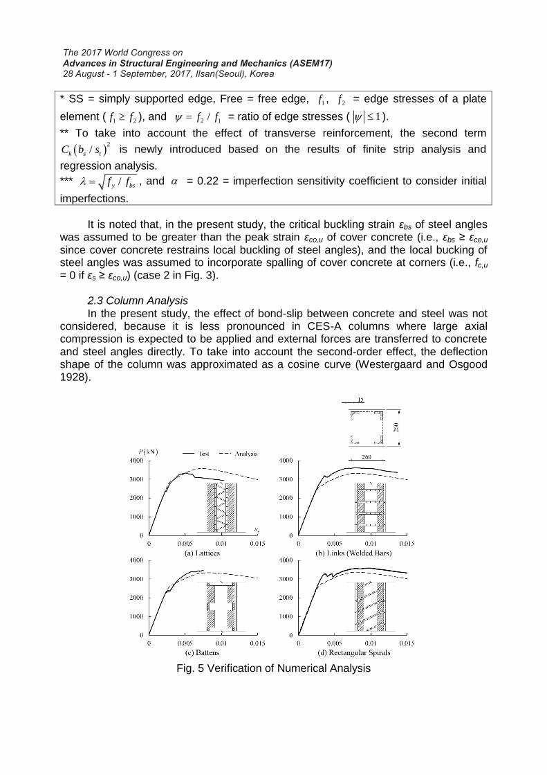
considered, because it is less pronounced in CES-A columns where large axial compression is expected to be applied and external forces are transferred to concrete and steel angles directly. To take into account the second-order effect, the deflection shape of the column was approximated as a cosine curve (Westergaard and Osgood 1928).
Fig. 5 Verification of Numerical Analysis
2.4 Verification For verification, the nonlinear numerical analysis results by the proposed model
were compared with the previous test results (Kim et al. 2014 and 2017). Fig. 5 shows the comparison. Although some discrepancies were observed in the behavior, the predictions (thin dashed lines) generally agreed with the test results (thick solid lines). 3. RESIDUAL STRENGTH AFTER COVER-SPALLING
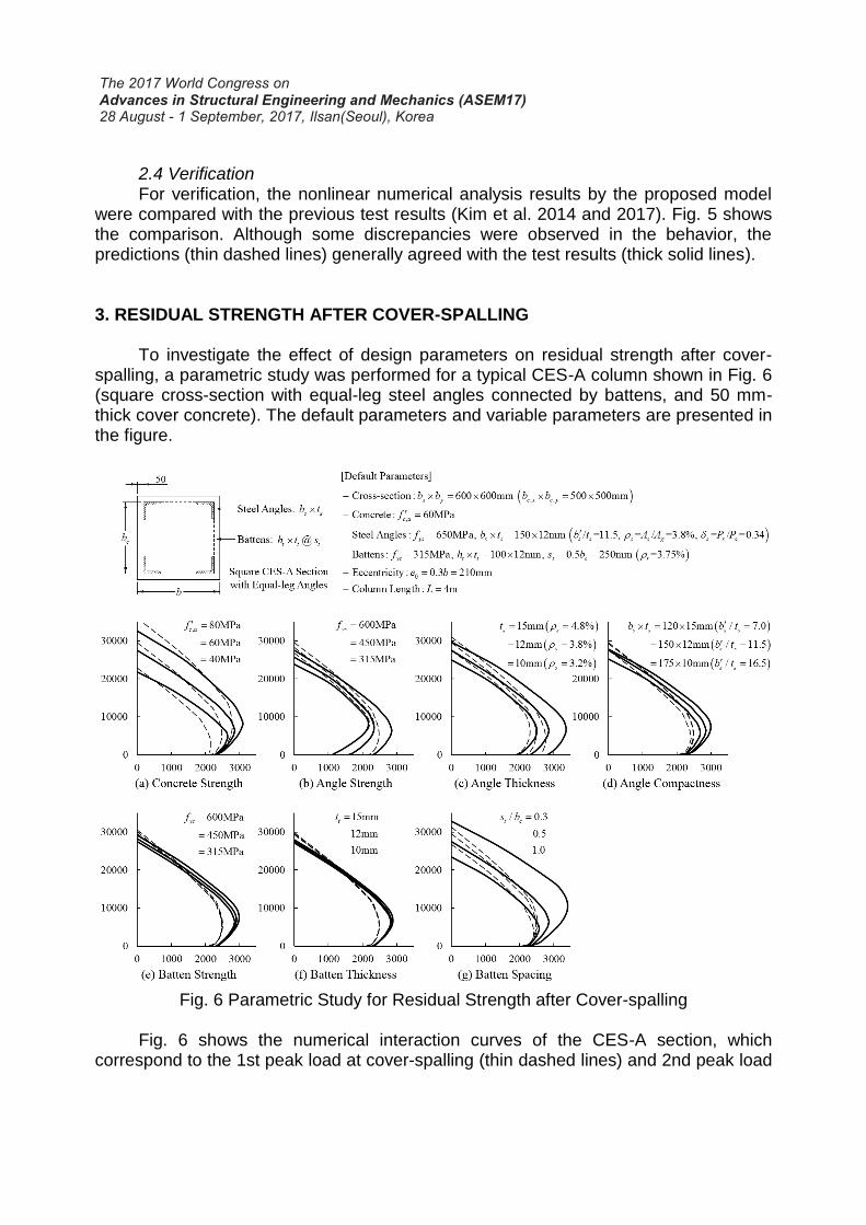
To investigate the effect of design parameters on residual strength after cover-spalling, a parametric study was performed for a typical CES-A column shown in Fig. 6 (square cross-section with equal-leg steel angles connected by battens, and 50 mm-thick cover concrete). The default parameters and variable parameters are presented in the figure.
Fig. 6 Parametric Study for Residual Strength after Cover-spalling
Fig. 6 shows the numerical interaction curves of the CES-A section, which
correspond to the 1st peak load at cover-spalling (thin dashed lines) and 2nd peak load
after cover-spalling (thick solid lines). As expected, the 2nd peak load (or residual strength) was affected by the design parameters, and in some cases, the 2nd peak load was greater than the 1st peak load: 1) as the steel contribution increased (in the cases of using higher strength (Fig. 6(b)) and/or thicker (Fig. 6(c)) steel angles), the residual strength in the tension-controlled zone (below the balanced failure point) was increased; whereas 2) as the confinement efficiency increased (in the cases of using more compact steel angles (Fig. 6(d)) and higher strength, thicker, and/or denser battens (Fig. 6(e), (f), (g))), the residual strength in the compression-controlled zone (above the balanced failure point) was increased. In the case of using higher strength concrete (Fig. 6(a)), the interaction curve in the compression-controlled zone was expanded, but the residual strength was decreased due to the decreased steel contribution. Especially in the practical range of axial load (generally in actual design, P≥0.1Agf'c according to the definition of compression members and e0/b≥0.1 to account for accidental eccentricity (ACI 318-14)), the 2nd peak load greater than the 1st peak load was more obvious.
The 2nd peak load or residual strength is a meaningful factor in seismic design and progressive collapse analysis. Thus, further research is required to predict the residual strength after spalling of cover concrete at corners. 4. CONCLUSIONS
To investigate the residual strength of CES-A columns, a numerical study was performed using a proposed analysis model, in which the strain compatibility, confinement effect of steel angles and transverse reinforcement, local buckling of steel angles and its effect on confinement, and premature spalling of cover concrete at corners were considered. For verification, the numerical analysis results were compared with the previous experimental study results, and to investigate the effect of design parameters, a parametric study was also conducted. The numerical investigation showed that when the steel contribution is high and the confinement efficiency is high, CES-A columns exhibit relatively large residual strength even after spalling of cover concrete at corners. REFERENCES American Concrete Institute (2014), Building Code Requirements for Structural
Concrete and Commentary (ACI 318-14), Farmington Hills, MI. Bambach, M.R. and Rasmussen, K.J.R. (2004(1)), “Effective widths of unstiffened
elements with stress gradient,” J. Struct. Eng., ASCE, 130(10), 1611-1619. Bambach, M.R., and Rasmussen, K.J.R. (2004(2)), “Design provisions for sections
containing unstiffened elements with stress gradient,” J. Struct. Eng., ASCE, 130(10), 1620-1628.
Collins, M.P., Mitchell, D., and MacGregor, J.G. (1993), “Structural design considerations for high-strength concrete,” Concrete International: Design and Construction, 15(5), 27-34.
Cusson, D. and Paultre, P. (1994), “High-strength concrete columns confined by rectangular ties,” J. Struct. Eng., ASCE, 120(3), 783-804.
Gerard, G. (1946), “Secant modulus method for determining plate instability above the proportionality limit,” Journal of the Aeronautical Sciences, 13(1), 38-44.
Kim, C.S., Park, H.G., Chung, K.S., and Choi, I.R. (2014), “Eccentric axial load capacity of high-strength steel - concrete composite columns of various sectional shapes,” J. Struct. Eng., ASCE, 140(4), 04013091-1-12.
Kim, C.S., Park, H.G., Lee, H.J., Choi, I.R., and Chung, K.S. (2017), “Eccentric axial load test for high-strength composite columns of various sectional configurations,” J. Struct. Eng., ASCE, 143(8), 04017075-1-14.
Mazzolani, F.M., Piluso, V., and Rizzano, G. (2011), “Local buckling of aluminum alloy angles under uniform compression,” J. Struct. Eng., ASCE, 137(2), 173-184.
Montuori, R. and Piluso, V. (2009), “Reinforced concrete columns strengthened with angles and battens subjected to eccentric load,” Eng. Struct., 31(2), 539-550.
Nagaprasad, P., Sahoo, D.R., and Rai, D.C. (2009), “Seismic strengthening of RC columns using external steel cage,” Earthquake Engng. Struct. Dyn., 38, 1563-1586.
Ramberg, W. and Osgood, W. (1943). “Description of stress–strain curves by three parameters,” NACA Technical Note No. 902.
Rasmussen, K.J.R. (2003), “Full-range stress-strain curves for stainless steel alloys,” Journal of Constructional Steel Research, 59(1), 47-61.
Razvi, S.R. and Saatcioglu, M. (1999), “Confinement model for high-strength concrete,” J. Struct. Eng., ASCE, 125(3), 281-289.
Saatcioglu, M. and Razvi, S.R. (1992), “Strength and ductility of confined concrete,” J. Struct. Eng., ASCE, 118(6), 1590-1607.
Stowell, E.Z. (1948), “A unified theory of plastic buckling of columns and plates,” National Advisory Committee for Aeronautics, Report No. 898, 127-137.
von Karman, T., Sechler, E.E., and Donnell, L.H. (1932), “The strength of thin plates in compression,” Transactions of ASME, 54, 53-57.
Westergaard, H.M. and Osgood, W.R. (1928), “Strength of steel columns.” Transactions of ASME, 50, 65-80.