Embed Size (px)
Citation preview
HBRC Journal (2013) 9, 134–143
Housing and Building National Research Center
HBRC Journal
http://ees.elsevier.com/hbrcj
Review of design codes of concrete encased steel
short columns under axial compression
K.Z. Soliman, A.I. Arafa, Tamer M. Elrakib *
Housing and Building National Research Centre, Cairo, Egypt
Received 27 September 2012; accepted 11 October 2012
*
E
hb
Pe
R
16
ht
KEYWORDS
Composite columns;
Concrete encased columns;
Confinement;
Ductility
Corresponding author.
-mail addresses: k.soliman@h
rc.edu.eg (A.I. Arafa), T.Ra
er review under responsibili
esearch Center.
Production an
87-4048 ª 2013 Housing and
tp://dx.doi.org/10.1016/j.hbrc
brc.edu.
kib@hbr
ty of Ho
d hostin
Buildin
j.2013.02
Abstract In recent years, the use of encased steel concrete columns has been increased significantly
in medium-rise or high-rise buildings. The aim of the present investigation is to assess experimen-
tally the current methods and codes for evaluating the ultimate load behavior of concrete encased
steel short columns. The current state of design provisions for composite columns from the Egyp-
tian codes ECP203-2007 and ECP-SC-LRFD-2012, as well as, American Institute of Steel Con-
struction, AISC-LRFD-2010, American Concrete Institute, ACI-318-2008, and British Standard
BS-5400-5 was reviewed. The axial capacity portion of both the encased steel section and the con-
crete section was also studied according to the previously mentioned codes. Ten encased steel con-
crete columns have been investigated experimentally to study the effect of concrete confinement and
different types of encased steel sections. The measured axial capacity of the tested ten composite
columns was compared with the values calculated by the above mentioned codes. It is concluded
that non-negligible discrepancies exist between codes and the experimental results as the confine-
ment effect was not considered in predicting both the strength and ductility of concrete. The con-
fining effect was obviously influenced by the shape of the encased steel section. The tube-shaped
steel section leads to better confinement than the SIB section. Among the used codes, the ECP-
SC-LRFD-2012 led to the most conservative results.ª 2013 Housing and Building National Research Center. Production and hosting by Elsevier B.V.
All rights reserved.
eg (K.Z. Soliman), A.arafa@
c.edu.eg (T.M. Elrakib).
using and Building National
g by Elsevier
g National Research Center. Produ
.002
Introduction
For the past two decades, concrete encased steel columns areused in tall buildings. They have the rigidity and stiffness ofconcrete, as well as, the strength and ductility of the steel sec-
tion. They also reduce the cross sectional dimensions which inturn makes them more slender and easy to erect. Compositecolumns can be classified as either hollow sections filled with
concrete or steel sections encased in concrete. The latter oneis considered in this paper. It offers high strength, ductility, fire
ction and hosting by Elsevier B.V. All rights reserved.
Table 1 Concrete compressive strength in the available codes.
Code Concrete Comment
ECP203-2007 0.67 fcu Refer to 0.85 · 0.80 (ratio between cylinder to cube strength) = 0.68
ECP-SC-LRFD-2012 Not limited –
ACI 318-08 0.85 fc0 Account for accidental eccentricities not considered in the analysis that may exist in a compression
member
AISC-LRFD-2010 0.85 fc0 The nominal compressive strength shall be computed assuming that concrete components in
compression have reached a stress of 0.85 fc0
BS 5400-Part 5-2002 0.67 fcu Refer to 0.85 · 0.80 (ratio between cylinder to cube strength) = 0.68
fcu is the 28th day cube strength of concrete, and fc0 is the 28th day cylinder strength of concrete.
Reviewing design codes of concrete encased short steel columns of design 135
protection for the steel section, and simplified beam to columnconnections. Different methods for the design of compositecolumns exist in codes of practice [1–5]. A composite column
may be treated in some methods as a steel column strength-ened by concrete. On the other hand, it may be treated as areinforced concrete column with special reinforcement. Fur-
thermore, the strength of a composite column may be evalu-ated as the sum of strengths of both components, concreteand steel reinforcements. Existing code differences may be
attributed to difference in design philosophy; i.e., strain distri-bution and compatibility. This discrepancy is referring to thedifferences in allowable material properties, limiting dimen-sions and safety factors [6–8].
Mimoune [9] studied theoretically the monotonic behaviorof composite columns under axial load and he concluded thatthe obtained results showed a difference between different
codes of practice. It was also stated that, the confinementcoefficients’ values need to be adjusted.
Paul and Samanta [10] assessed the axial capacity of a con-
crete encased steel short column by two different codes, theEuro Code EC4 and the Load and Resistance FactorDesign-American Institute of Steel Construction AISC-LFRD
code using a 3D finite element model. They reported that theEuro Code EC4 method shows more accurate predictions ofcomposite column strength. However, neither EC4 nor AISCprovisions explicitly consider any increase in the strength or
ductility of concrete due to transverse ties, i.e.; the confinementeffect was not included so it is of importance to experimentallyinvestigate the concrete confinement effect on the concrete
encased steel composite columns.The literature review has also indicated the scarcity of
experimental data on concrete encased steel short column.
Accordingly, the current research has the followinggoals
� Carrying out an experimental program that would lead to abetter understanding of the behavior of the concreteencased steel short column.� Analyzing the response of the tested columns in terms of
strength and ductility to provide a database useful fordeveloping design guidelines.� Comparison between the available codes and formulas.
To achieve such goals, an experimental program compris-ing tests of ten encased steel composite concrete columns
designated as CI to C10 was conducted. The tested parametersare concrete contribution, concrete confinement through using
different stirrups ratio and also the different types of encasedsteel sections.
Brief description of the available design codes for compositecolumns
Different concepts for the design of composite columns exist in
the available codes of practice [1–5], will be summarizedhereinafter,
ECP 203-2007 [1]
The design of composite columns is based on the limit statedesign method with loading factors and partial safety for mate-rials. The strength of a composite column is computed as for
reinforced concrete members. Failure is defined in terms of a0.002 strain limit for any concrete fiber. However, the slender-ness and area parameters are modified for the presence of the
steel section. Load transfer should be provided by direct bear-ing at the connections. The load carried by the concrete shallnot exceed the allowable bearing stress to avoid overstressingof concrete.
ECP-Sc-LRFD-2012 [2]
It is based on limit state design with loading factors, partial
safety for materials, modified yield stress, modified young’smodulus, modified radius of gyration and numerical quantifi-cation. The design of composite columns is based on the de-sign equations for steel columns. However, the slenderness
and area parameters are modified for the presence of con-crete. Load transfer should be provided by direct bearing atthe connections. The load carried by the concrete shall not ex-
ceed the allowable bearing stress to avoid overstressing ofconcrete.
ACI-318-08 [3]
It uses the limit state design format with factors and capacityreduction factors. The strength of a composite column is com-puted as for reinforced concrete members. Failure is defined in
terms of a 0.002 strain limit for any concrete fiber. The expres-sion for equivalent stiffness includes a creep factor, andcracked concrete stiffness is considered. Minimum eccentrici-
ties are specified to cover construction tolerances.
AISC-LRFD-2010 [4]
The load and resistance factor design uses the limit state design
method with loading factors and capacity reduction factors.
Table 2 Equivalent stiffness in the available codes.
Code Ec Comments
ECP203-2007 Ec = 4400ffiffiffiffiffiffifcup
(N/mm2) A cracked section is used, with a creep factor
ECP-SC-LRFD-2012 22000–31000 N/mm2 for fcu = 25–50 N/mm2 –
ACI-318-08 Ec = 4700ffiffiffiffiffifc0p
(N/mm2) A cracked section is used, with a creep factor
AISC-LRFD-2010 Ec = 0.043 wc1.5 ffiffiffiffiffi
fc0p
(N/mm2) A cracked section is used, (wc = unit weight of concrete in kg/m3)
BS 5400-Part 5-2002 Ec = 670 fcu A cracked section is used, with a creep factor
Table 3 Properties of the used materials in the available codes.
Code Concrete strength Steel yield Strength
ECP203-2007 fcu P 20 N/mm2 fy 6 350 N/mm2
ECP-SC-LRFD-2012 25 N/mm2 < fcu < 50 N/mm2 (Not limited)
ACI-318-08 fc’ > 17 N/mm2 fy < 350 N/mm2
AISC-LRFD-2010 21 N/mm2 < fc’ < 70 N/mm2 fy < 525 N/mm2
BS 5400-Part 5-2002 fcu > 25 N/mm2 Grade 430 and 500 N/mm2
Table 4 Steel and concrete contributions in the available codes.
Code Specifications
ECP203-2007 1% 6 ALongitudinal bars+steel section 6 6% Anet area of concrete
ECP-SC-LRFD-2012 Asteel section P 4% Agross of column
ACI-318-08 1% 6 ALongitudinal bars 6 8% Anet area of concrete
AISC-LRFD-2010 Asteel shape/Agross of the member P 1%
ALongitudinal bars 6 0.4% Agross area
BS 5400-Part 5-2002 0.15 < ac < 0.80, ac ¼ 0:45�Ac�fcuNu
where, ac: concrete contribution
Table 5 Slenderness ranges in the available codes.
Code Specifications
ECP203-2007 k(slenderness ratio) 6 50, for braced building
k 6 35, for unbraced building
ECP-SC-LRFD-2012 k = (L(Fym/Em)^0.5)/prmTwo cases, k 6 1.1 and k P 1.1
ACI-318-08 k = kl(Buckling length)/r(Radius of gyration for steel and concrete)
AISC-LRFD-2010 Based on the ratio between the nominal compressive axial load Pno, and elastic critical buckling load Pe
The available compressive strength Pn P the specified for the bare steel member
BS 5400-Part 5-2002 leffb � 30 short column
Ly/b(breadth of column) 6 12, and
Lx/h(depth of column section) 6 12
136 K.Z. Soliman et al.
The design of composite columns is based on the design equa-
tions for steel columns. The slenderness and area parametersare modified for the presence of concrete. Load transfer shouldbe provided by direct bearing at the connections.
BS 5400-Part 5 [5]
It is based on limit state design with loading factors and partialsafety for materials. Reduced concrete properties are used to
account for the effect of creep and the use of the un-crackedconcrete section in stiffness calculation. The slendernessparameter is consistent with the design of steel columns as
the method reduces to the bare steel column design when the
concrete portion is removed.
Comparison between different codes
From above, it is obvious that there are differences between
codes in design philosophy [6]. However, brief comparisonsof recommended values for concrete strength, equivalent stiff-ness, and limits of extreme values of concrete crushing and
steel yield strength, are summarized in Tables 1–3. In addition,limits of steel and concrete contribution as well as limits of
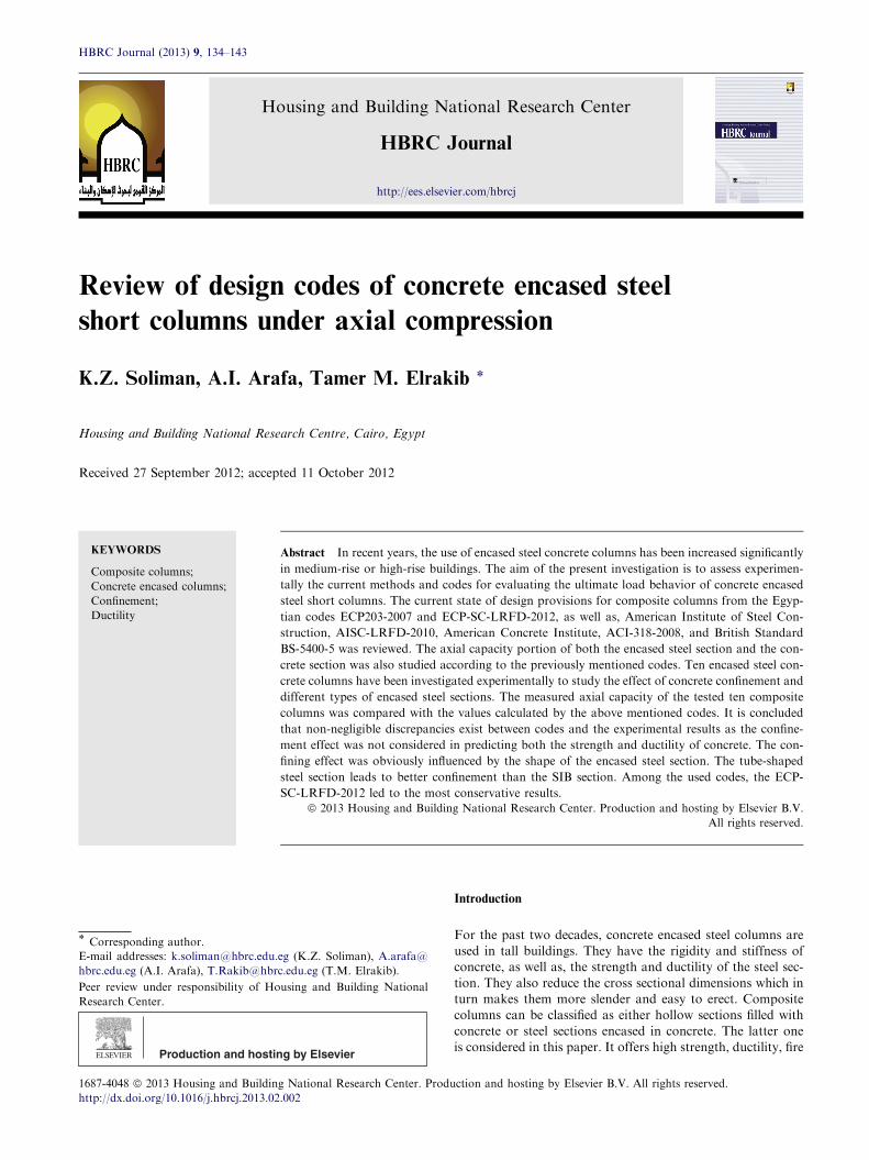
Stirrups 5 8/m’
Experimental Program
Plastic pipe 100mm
Steel S.I.B. No. 10
Stirrups 10 8/m’
Control Specimen
Steel pipe 100mm
fcu=25MPa
Wood S.I.B.
Fig. 1 Experimental program.
R8 @200 for C1
R8 @
Steel Diam.
Steel S.I.BNo. 10
R8 @100 for C6
R8 @
R8 @200 for C4R8 @100 for C9
Fig. 2 Details of th
Table 6 Properties of the tested composite columns, fcu = 25 MPa
Group Col. Section properties
Dimension b · d (mm) Asa St
1 C1 200 · 200 4T12 5R
C2 200 · 200 4T12 5R
C3 200 · 200 4T12 5R
C4 200 · 200 4T12 5R
C5 200 · 200 4T12 5R
2 C6 200 · 200 4T12 10
C7 200 · 200 4T12 10
C8 200 · 200 4T12 10
C9 200 · 200 4T12 10
C10 200 · 200 4T12 10
T denotes high grade deformed bars, and the following number indicates
R denotes mild steel, and the following number indicates the diameter ina As is the longitudinal reinforcement.b Ass is the area of encased steel section.
Reviewing design codes of concrete encased short steel columns of design 137
slenderness for concrete encased columns are given in Tables 4and 5.
Experimental test program
Characteristics of test specimens
Ten encased steel composite concrete columns were designedto investigate the effect of the tested parameters which are
the concrete contribution, the concrete confinement throughusing different stirrups ratio, as well as, different types of en-cased steel sections, Ass. Determination of the axial capacity
portion for both the encased steel section and the concretesection is also investigated. The concrete compressive strength,fcu was 25 MPa for all columns. The yielding strength, fy, of
the encased sections was 240 MPa. All columns had a squarecross section of size 200 · 200 mm with entire height1400 mm, and were longitudinally reinforced by 4 bars of
200 for C2
pipe100, th.3.5mm
Plastic pipeDiam.100, th.3mm
Wood S.I.Bth. 10mm
100 for C7R8 @200 for C3R8 @100 for C8
R8 @200 for C5R8 @100 for C10
e tested columns.
.
Ac (net) (mm2) bAss (mm2)
irrups Steel Sec.
8/m0 ___ 40,000 ___
8/m0 Steel pipe Ø100 37,928 1099
8/m0 Plastic pipe Ø100 38,606 —
8/m0 Steel S.I.B.10 38,488 1060
8/m0 Wood S.I.B 36,748 —
R8/m0 ___ 40,000 ___
R8/m0 Steel pipe Ø100 37928 1099
R8/m0 Plastic pipe Ø100 38,606 —
R8/m0 Steel S.I.B.10 38,488 1060
R8/m0 Wood S.I.B 36,748 —
the diameter in mm.
mm.
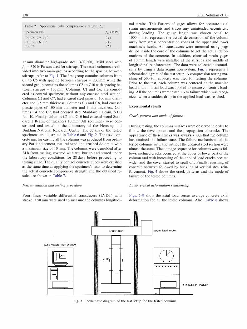
Table 7 Specimens’ cube compressive strength, fcu.
Specimen No. fcu (MPa)
C4, C5, C9, C10 23.1
C1, C2, C6, C7 23.7
C3, C8 22.1
138 K.Z. Soliman et al.
12 mm diameter high-grade steel (400/600). Mild steel withfy = 320 MPa was used for stirrups. The tested columns are di-vided into two main groups according to the spacing between
stirrups, refer to Fig. 1. The first group contains columns fromC1 to C5 with spacing between stirrups = 200 mm while thesecond group contains the columns C5 to C10 with spacing be-
tween stirrups = 100 mm. Columns, C1 and C6, are consid-ered as control specimens without any encased steel section.Columns C2 and C7, had encased steel pipes of 100 mm diam-
eter and 3.5 mm thickness. Columns C3 and C8, had encasedplastic pipes of 100 mm diameter and 3 mm thickness. Col-umns C4 and C9, had encased steel Standard I Beam, S.I.B
No. 10. Finally, columns C5 and C10 had encased wood Stan-dard I Beam, of thickness 10 mm. All specimens were con-structed and tested in the laboratory of the Housing andBuilding National Research Centre. The details of the tested
specimens are illustrated in Table 6 and Fig. 2. The used con-crete mix for casting all the columns was produced from ordin-ary Portland cement, natural sand and crushed dolomite with
a maximum size of 10 mm. The columns were demolded after24 h from casting, covered with wet burlap and stored underthe laboratory conditions for 28 days before proceeding to
testing stage. The quality control concrete cubes were crushedat the same time as applying the specimen’s tests to determinethe actual concrete compressive strength and the obtained re-
sults are shown in Table 7.
Instrumentation and testing procedure
Four linear variable differential transducers (LVDT) with
stroke ±50 mm were used to measure the columns longitudi-
Fig. 3 Schematic diagram of the t
nal strains. This Pattern of gages allows for accurate axialstrain measurements and traces any unintended eccentricityduring loading. The gauge length was chosen equal to
1000 mm to represent the actual deformation of the columnaway from stress concentration zones at the upper and lowermachine’s heads. All transducers were mounted using pegs
drilled inside the core of the columns to get the actual defor-mations of the concrete. In addition, electrical strain gagesof 10 mm length were installed at the stirrups and middle of
longitudinal reinforcement. The data were collected automati-cally by using a data acquisition system. Fig. 3 represents aschematic diagram of the test setup. A compression testing ma-chine of 500 ton capacity was used for testing the columns.
Prior to the test, each column was centered at the machinehead and an initial load was applied to ensure concentric load-ing. All the columns were tested up to failure which was recog-
nized when a sudden drop in the applied load was reached.
Experimental results
Crack pattern and mode of failure
During testing, the columns surfaces were observed in order tofollow the development and the propagation of cracks. Theappearance of these cracks was always a sign that the column
has attained the failure state. The failure mechanisms of thetested columns with and without the encased steel section werealmost the same. The damage sequence for columns was as fol-
lows: inclined cracks occurred at the upper or lower part of thecolumn and with increasing of the applied load cracks becamewider and the cover started to spall off. Finally, crushing ofconcrete occurred followed by buckling of vertical steel rein-
forcement. Fig. 4 shows the crack patterns and the mode offailure of the tested columns.
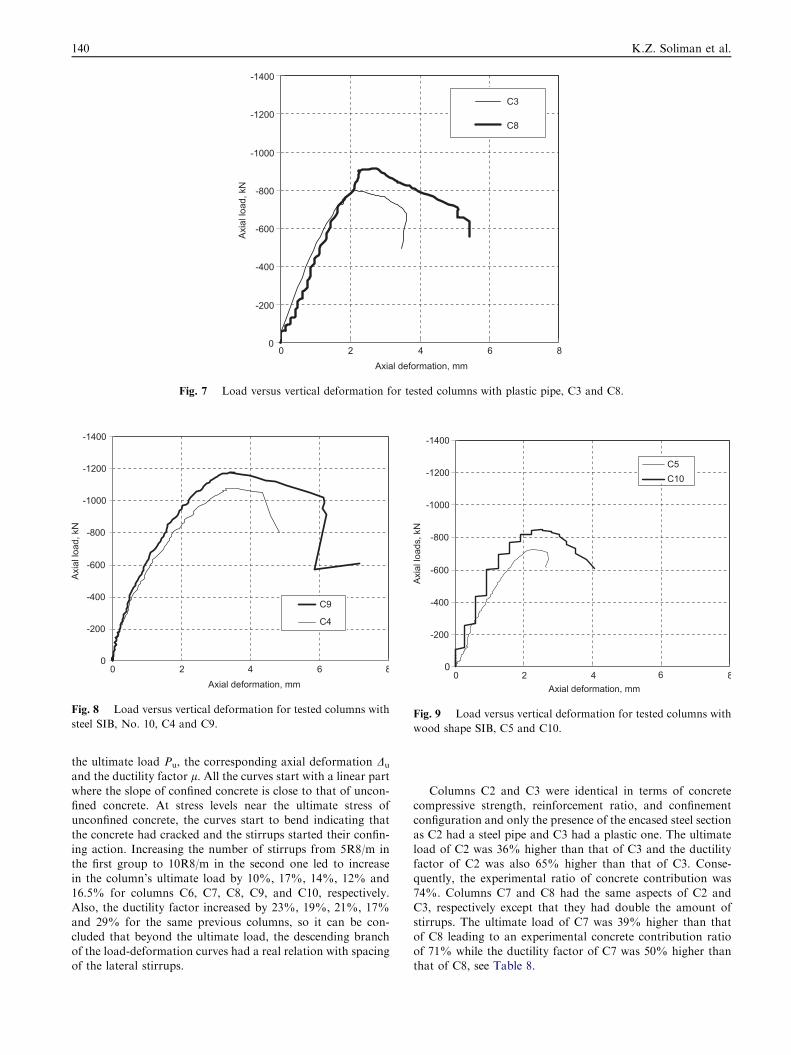
Load-vertical deformation relationship
Figs. 5–9 show the axial load versus average concrete axialdeformation for all the tested columns. Also, Table 8 shows
est setup for the tested columns.
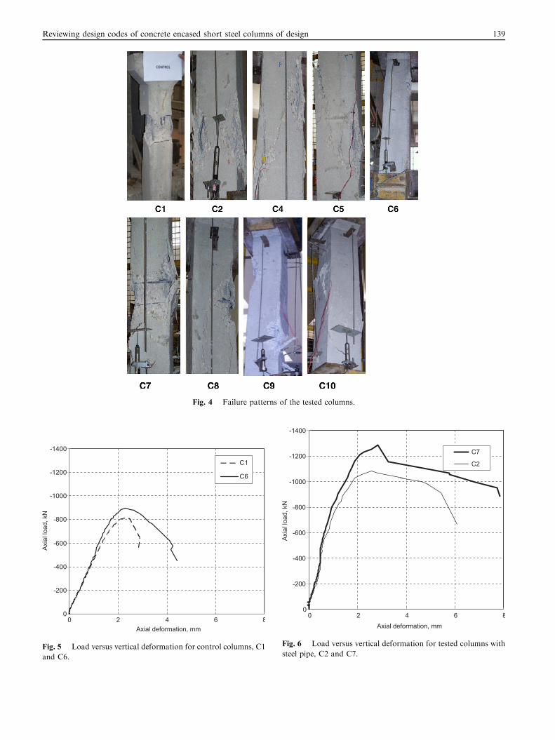
Fig. 4 Failure patterns of the tested columns.
-1400
-1200
-1000
-800
-600
-400
-200
00 2 4 6 8
Axial deformation, mm
Axia
l loa
d, k
N
C1
C6
Fig. 5 Load versus vertical deformation for control columns, C1
and C6.
-1400
-1200
-1000
-800
-600
-400
-200
00 2 4 6 8
Axial deformation, mm
Axia
l loa
d, k
N
C7
C2
Fig. 6 Load versus vertical deformation for tested columns with
steel pipe, C2 and C7.
Reviewing design codes of concrete encased short steel columns of design 139
-1400
-1200
-1000
-800
-600
-400
-200
00 2 4 6 8
Axial deformation, mm
Axia
l loa
d, k
N
C3
C8
Fig. 7 Load versus vertical deformation for tested columns with plastic pipe, C3 and C8.
-1400
-1200
-1000
-800
-600
-400
-200
00 2 4 6 8
Axial deformation, mm
Axia
l loa
d, k
N
C9
C4
Fig. 8 Load versus vertical deformation for tested columns with
steel SIB, No. 10, C4 and C9.
-1400
-1200
-1000
-800
-600
-400
-200
00 2 4 6 8
Axial deformation, mm
Axia
l loa
ds, k
N
C5C10
Fig. 9 Load versus vertical deformation for tested columns with
wood shape SIB, C5 and C10.
140 K.Z. Soliman et al.
the ultimate load Pu, the corresponding axial deformation Du
and the ductility factor l. All the curves start with a linear part
where the slope of confined concrete is close to that of uncon-fined concrete. At stress levels near the ultimate stress ofunconfined concrete, the curves start to bend indicating that
the concrete had cracked and the stirrups started their confin-ing action. Increasing the number of stirrups from 5R8/m inthe first group to 10R8/m in the second one led to increase
in the column’s ultimate load by 10%, 17%, 14%, 12% and16.5% for columns C6, C7, C8, C9, and C10, respectively.Also, the ductility factor increased by 23%, 19%, 21%, 17%
and 29% for the same previous columns, so it can be con-cluded that beyond the ultimate load, the descending branchof the load-deformation curves had a real relation with spacingof the lateral stirrups.
Columns C2 and C3 were identical in terms of concretecompressive strength, reinforcement ratio, and confinementconfiguration and only the presence of the encased steel section
as C2 had a steel pipe and C3 had a plastic one. The ultimateload of C2 was 36% higher than that of C3 and the ductilityfactor of C2 was also 65% higher than that of C3. Conse-
quently, the experimental ratio of concrete contribution was74%. Columns C7 and C8 had the same aspects of C2 andC3, respectively except that they had double the amount of
stirrups. The ultimate load of C7 was 39% higher than thatof C8 leading to an experimental concrete contribution ratioof 71% while the ductility factor of C7 was 50% higher thanthat of C8, see Table 8.
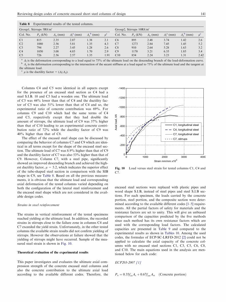
Table 8 Experimental results of the tested columns.
Group1, Stirrups 5R8/m0 Group2, Stirrups 10R8/m0
Col. No. Pu (kN) Du (mm) Dfa (mm) Dy
b (mm) lc Col. No. Pu (kN) Du (mm) Dfa (mm) Dy
b (mm) lc
C1 815 2.35 2.87 1.38 2.1 C6 895 2.48 3.74 1.42 2.6
C2 1080 2.56 5.81 1.35 4.3 C7 1273 2.84 7.45 1.45 5.2
C3 794 2.27 3.45 1.28 2.6 C8 910 2.64 5.28 1.63 3.2
C4 1050 3.08 4.85 1.70 2.9 C9 1170 3.21 6.35 1.85 3.4
C5 726 2.56 2.57 1.35 1.91 C10 854 2.24 3.23 1.31 2.42
a Df is the deformation corresponding to a load equal to 75% of the ultimate load on the descending branch of the load-deformation curve.b Dy is the deformation corresponding to the intersection of the secant stiffness at a load equal to 75% of the ultimate load and the tangent at
the ultimate load.c l is the ductility factor = (Df/Du).
-1400
-1200
-1000
-800
-600
-400
-200
00 1000 2000 3000 4000
Strain mm/mm x10-6
Axia
l loa
d, k
N
C1, longitudinal steel
C4, longitudinal steelC7, longitudinal steel
C7, stirrups
Fig. 10 Load versus steel strain for tested columns C1, C4 and
C7.
Reviewing design codes of concrete encased short steel columns of design 141
Columns C4 and C5 were identical in all aspects exceptfor the presence of an encased steel section as C4 had a
steel S.I.B. 10 and C5 had a wooden one. The ultimate loadof C5 was 44% lower than that of C4 and the ductility fac-tor of C5 was also 51% lower than that of C4 and so, theexperimental ratio of concrete contribution was 69%. For
columns C9 and C10 which had the same terms of C4and C5, respectively except that they had double theamount of stirrups, the ultimate load of C9 was 37% higher
than that of C10 leading to an experimental concrete contri-bution ratio of 72% while the ductility factor of C9 was40% higher than that of C8.
The effect of the encased steel shape can be discussed bycomparing the behavior of columns C7 and C9 which are iden-tical in all terms except for the shape of the encased steel sec-tion. The ultimate load of C7 was 8.9% higher than that of C9
and the ductility factor of C7 was also 53% higher than that ofC9. However, Column C7, with a steel pipe, significantlyshowed an improved descending branch and achieved the high-
est ductility factor, l = 5.2, which indicates the superior effectof the tube-shaped steel section in comparison with the SIBshape in C9, see Table 8. Based on all the previous measure-
ments, it is obvious that the ultimate load and correspondingaxial deformation of the tested columns varied depending onboth the configuration of the lateral steel reinforcement and
the encased steel shape which are not considered in the avail-able design codes.
Strains in steel reinforcement
The strains in vertical reinforcement of the tested specimensreached yielding at the ultimate load. In addition, the recordedstrains in stirrups close to the failure zone in columns C4 and
C7 exceeded the yield strain. Unfortunately, in the other testedcolumns the available strain results did not confirm yielding ofstirrups. However the observations at failure showed that the
yielding of stirrups might have occurred. Sample of the mea-sured steel strain is shown in Fig. 10.
Theoretical evaluation of the experimental results
This paper investigates and evaluates the ultimate axial com-pression strength of the concrete encased steel columns and
also the concrete contribution to the ultimate axial loadaccording to the available different codes. Therefore, the
encased steel sections were replaced with plastic pipes andwood shape S.I.B, instead of steel pipes and steel S.I.B sec-
tions. For each specimen, the loads carried by the concreteportion, steel portion, and the composite section were deter-mined according to the available different codes [1–5] require-
ments. All the partial factors of safety for materials and theresistance factors are set to unity. This will give an unbiasedcomparison of the capacities predicted by the five methods
since each method has its own resistance factors which areused with the corresponding load factors. The calculatedcapacities are presented in Table 9 and compared to theexperimental results as shown in Tables 10. Among the used
codes, the formulas of ECP-SC-LRFD-2012 [2] could not beapplied to calculate the axial capacity of the concrete col-umns with no encased steel sections C1, C3, C5, C6, C8,
and C10. The main equations used in the analysis are men-tioned below for each code:
ECP203-2007 [1]
Pu ¼ 0:35fcuAc þ 0:67fyscAsc ðConcrete portionÞ
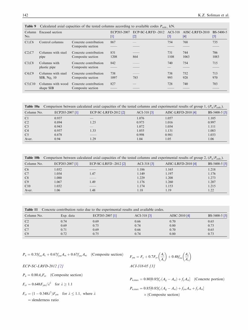
Table 10a Comparison between calculated axial capacities of the tested columns and experimental results of group 1, (Pu/Pcalc.).
Column No. ECP203-2007 [1] ECP-SC-LRFD-2012 [2] ACI-318 [3] AISC-LRFD-2010 [4] BS-5400-5 [5]
C1 0.937 — 1.076 1.057 1.105
C2 0.894 1.25 0.975 1.016 0.997
C3 0.943 — 1.072 1.054 1.111
C4 0.957 1.33 1.055 1.131 1.083
C5 0.878 —— 0.998 0.981 1.033
Aver. 0.94 1.29 1.04 1.05 1.06
Table 9 Calculated axial capacities of the tested columns according to available codes Pcalc., kN.
Column
No.
Encased section ECP203-2007
[1]
ECP-SC-LRFD -2012
[2]
ACI-318
[3]
AISC-LRFD-2010
[4]
BS-5400-5
[5]
C1,C6 Control columns Concrete contribution 867 — 754 768 735
Composite section —— —— —— —— ——
C2,C7 Columns with steel
pipe
Concrete contribution 831 —— 731 744 706
Composite section 1208 864 1108 1063 1083
C3,C8 Columns with
plastic pipe
Concrete contribution 842 —— 740 754 715
Composite section —— —— — —— ——
C4,C9 Columns with steel
SIB, No. 10
Concrete contribution 738 —— 738 752 713
Composite section 1097 785 995 928 970
C5,C10 Columns with wood
shape SIB
Concrete contribution 827 — 728 740 703
Composite section —— —— —— —— ——
Table 10b Comparison between calculated axial capacities of the tested columns and experimental results of group 2, (Pu/Pcalc.).
Column No. ECP203-2007 [1] ECP-SC-LRFD -2012 [2] ACI-318 [3] AISC-LRFD-2010 [4] BS-5400-5 [5]
C6 1.032 —— 1.186 1.165 1.218
C7 1.054 1.47 1.149 1.197 1.176
C8 1.080 —— 1.229 1.208 1.273
C9 1.067 1.49 1.176 1.260 1.207
C10 1.032 —— 1.174 1.153 1.215
Aver. 1.06 1.48 1.18 1.19 1.22
Table 11 Concrete contribution ratio due to the experimental results and available codes.
Column No. Exp. data ECP203-2007 [1] ACI-318 [3] AISC-2010 [4] BS-5400-5 [5]
C2 0.74 0.69 0.66 0.70 0.65
C4 0.69 0.75 0.74 0.80 0.73
C7 0.71 0.69 0.66 0.70 0.65
C9 0.72 0.75 0.74 0.80 0.73
142 K.Z. Soliman et al.
Pu ¼ 0:35fcuAc þ 0:67fyssAss þ 0:67fyscAsc ðComposite sectionÞ
ECP-SC-LRFD-2012 [2]
Pu ¼ 0:80AsFcr ðComposite sectionÞ
Fcr ¼ 0:648Fym=k2 for k � 1:1
Fcr ¼ ð1� 0:348k2ÞFym for k � 1:1; where k
¼ slenderness ratio
Fym ¼ Fy þ 0:7Fyr
Ar
As
� �þ 0:48fcu
Ac
As
� �
ACI-318-05 [3]
Pn;max ¼ 0:80½0:85fc0 ðAg � AstÞ þ fyAst� ðConcrete portionÞ
Pn;max ¼ 0:85½0:85fc0 ðAg � AstÞ þ fyssAss þ fyAst�� ðComposite sectionÞ
Reviewing design codes of concrete encased short steel columns of design 143
AISC-LRFD-2010 [4]
Pno ¼ ½0:85fc0Ac þ fyAs þ FysrAsr� ðComposite sectionÞ
Pe ¼ p2ðEIeffÞ=ðKLÞ2
Pn ¼ 0:75� Pno � 0:658PnoPe
h i; if
Pno
Pe
� 2:25
BS 5400-Part 5 [5]
ac ¼0:45� Ac � fcu
Nu
ðConcrete contribution ratioÞ
Nu ¼ 0:91Asfy þ 0:87Arfry þ 0:45Acfcu ðShort columnÞ
Nay ¼ 0:85K1yNu if ac is not applicable ðComposite columnÞ
Referring to Table 9, it is noticed that the calculated axial
capacities of the first and second group are the same as the usedcodes and do not consider the confinement effect for predictingthe ultimate axial strength of the columns. Referring to Table
10, the comparitive studies with the experimental results showthat the predicted results are generally lower than the test re-sults which means that the calculated column strengths usingthe five previous codes are almost on the conservative side.
For group 1, ACI-318 [3] gives the closest prediction with anaverage of 4% lower than the test results and ECP-SC-LRFD-2012 [2] gives the most conservative results with an
average of 29% lower than the test results. For group 2,ECP203-2007 [1] gives the closest prediction with an averageof 6% lower than the test results and ECP-SC-LRFD-2012
[2] gives the most conservative values with an average of 48%lower than the test results. It is clear that considerable discrep-ancies exist between codes and the experimental data especiallyfor group 2 which has excess stirrups due to neglecting of the
stirrups confinement and the encased steel shape in these codes.On the other hand, the calculated ratios of concrete contribu-tion ranged between 0.66 and 0.80 according to codes [1,3–5],
and it varied from 0.69 to 0.74 according to experimentalresults, see Table 11.
Conclusions
Within the present scope of work and investigation carriedout, the following conclusions may be drawn:
1. A non-negligible difference between the available codes ofpractice and the experimental results is shown. The intro-
duction of confinement coefficients has a great influenceon the ultimate calculated axial loads.
2. The values of confinement coefficients need to be adjusted
in the used codes as they neglect the increase in strengthand ductility of columns due to transverse ties.
3. The confining effect is obviously influenced by the shape of
the encased steel section. The tube-shaped steel section ledto better confinement than the SIB section which resulted ina noticeable increase in both ductility and ultimate axialcapacity of the columns.
4. The calculated column strengths using the five previouscodes are found to be mostly conservative when comparedwith the experimentally obtained test results. However, the
ECP-SC-LRFD-2012 formula led to the most conservativeresults.
5. Finally, the concrete contribution is mainly dependent on
the number of ties and shear transfer between the concreteand steel sections. Despite this, no specific requirements forcalculating shear transfer between the encased steel sectionand concrete are available in the design codes. Future
researches are needed to cover this point.
Acknowledgement
The researchers express their gratitude to the staff of ‘‘Rein-forced Concrete Institute’’, Housing and Building NationalResearch Centre for their great effort through all experimental
stages of this research.
References
[1] Egyptian Code of Practice for Design and Construction of
Concrete Structures, ECP 203, Housing and Building National
Research Center, 2007.
[2] Egyptian Code of Practice for Steel Construction (ECP-SC-
LRFD), Housing and Building National Research Center, 2012.
[3] Building Code Requirements for Reinforced Concrete,
American Concrete Institute, ACI 318, Detroit, 2008.
[4] Specification for Structural Steel Buildings, (AISC-LRFD),
American Institute of Steel Construction, Chicago, Illinois, 2010.
[5] Steel, Concrete and Composite Bridges, Part 5, (BS.5400-5):
Code of Practice for Design of Composite Bridges, 2002.
[6] S. El-Tawil, G. Gregory, Strength and ductility of concrete
encased composite columns, J. Struct. Eng. 125 (1999) 1009–
1019.
[7] C. Weng, S. Yen, Comparisons of concrete-encased composite
column strength provisions of ACI code and AISC specification,
Eng. Struct. 24 (2002) 59–72.
[8] N. Shanmugam, B. Lakshmi, State of the art report on steel–
concrete composite columns, J. Constr. Steel Res. 57 (2001)
1041–1080.
[9] M. Mimoune, Design of Steel Concrete Composite Columns
Subject to Axial Compression, Constantine University Algeria
35 (2010) 201–207.
[10] A. Paul, A. Samanta, Review of design practice of concrete
encased steel short column under axial load, Int. J. Earth Sci.
Eng. 4 (2011) 608–611.