Embed Size (px)
Citation preview

Dow.com
Revisions to ASTM D7310 “Standard Guide for Defect Detection and Rating of Plastic Films Using Optical Sensors”
ANTEC 2017Brenda Colegrove, The Dow Chemical CompanyRichard Garner, Borealis
SPE ANTEC® Anaheim 2017 / 1370

Participating Companies
2
SPE ANTEC® Anaheim 2017 / 1371

ASTM D3351
Visual/projector
ASTM D7310
Optical Imaging
Historical Perspective on ASTM Gel Standards
Test MethodIssued 1993Withdrawn 2000
GuideIssued 2007Revised 2011
Sample Prep
Film Flat or tubular extrusion
Gel Definition
“Plastic nodule not blendedwith matrix”
Excludes foreign particles
“Any entity large enough to be detected by an optical sensor”; polymer as well as foreign particles
Gel Size & Precision
400-800m, > 800m
Counts per 1520 cm2 (4 layers)
Per agreement between supplier and customer
Reporting Counts per 1520 cm2
(≤100m thickness)
None
Very different!
PracticeIssued 1992Revised 2001, 2009, 2013, 2014
ASTM D3596
PVC –visual/light box
Formulated with stabilizer & carbon blackCompression molded sheet – conditions given
Hard particle of resin which will not fuse when the plasticmass is subjected to set conditions of hot processing.
Clear, unpigmented area.
A. >500m, 1
B. 400-500m, 5
C. 300-400m, 12
Counts per 232 cm2
(500 m thickness)
3
SPE ANTEC® Anaheim 2017 / 1372

Evolution of an ASTM Measurement* Standards
4
Guide
• Def - a compendium of information or series of options that does not recommend a specific course of action.
• ASTM D7310 “Defect Detection and Rating of Plastic Films Using Optical Sensors”
Practice
• Def - a definitive set of instructions for performing one or more specific operations that does not produce a test result.
• E.g. application, assessment, cleaning, collection, decontamination, inspection, installation, preparation, sampling, screening, and training.
• ASTM D3596 “Determination of Gels (Fisheyes) In General-Purpose Poly(Vinyl Chloride) (PVC) Resins”
Method
• Def - a definitive procedure that produces a specific test result.
• Precision and bias is reported (method capability)
• ASTM D3351 “Gel Count of Plastic Film” (Withdrawn)Sp
ecif
icG
en
era
l
Go
al fo
r
revis
ion
*Does not include Classification, Specification, Terminology,
SPE ANTEC® Anaheim 2017 / 1373
Definitions — Clarification of “defect”
5
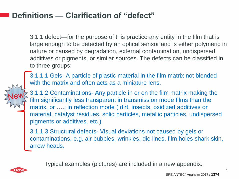
3.1.1 defect—for the purpose of this practice any entity in the film that is
large enough to be detected by an optical sensor and is either polymeric in
nature or caused by degradation, external contamination, undispersed
additives or pigments, or similar sources. The defects can be classified in
to three groups:
3.1.1.1 Gels- A particle of plastic material in the film matrix not blended
with the matrix and often acts as a miniature lens.
3.1.1.2 Contaminations- Any particle in or on the film matrix making the
film significantly less transparent in transmission mode films than the
matrix, or ….; in reflection mode ( dirt, insects, oxidized additives or
material, catalyst residues, solid particles, metallic particles, undispersed
pigments or additives, etc.)
3.1.1.3 Structural defects- Visual deviations not caused by gels or
contaminations, e.g. air bubbles, wrinkles, die lines, film holes shark skin,
arrow heads.
Typical examples (pictures) are included in a new appendix.
SPE ANTEC® Anaheim 2017 / 1374

Added Definitions
6
3.1.2 parcel—a user defined smallest area of inspected film for statistical
analysis to which a detected defect can be attributed. The statistical
evaluation is based on number of parcels.
3.1.3 effective pixel size—distance between adjacent, individual pixels
(picture elements) in the analyzed image The effective pixel size of the
optical system is determined by the physical pixel size of the sensor and
a magnification factor.
3.1.4 resolution—representing the optical smallest pixel that is used for
object size calculation.
3.1.5 Optical resolution—Smallest resolvable distance.= pixel size x 2.3
(area = 4 pixels)
SPE ANTEC® Anaheim 2017 / 1375

Size Verification Procedure
Calibration object – A transparent plastic substrate printed with circular
black points ranging in diameter from 100 to 3000 microns (certified by
vendor or confirmed with optical microscopy).
• Place object on running film
• Capture image
• Compare measured diameters to certified values
• Determine resolution from known diameter and number of pixels
• Hardware calibration is performed by camera vendor
7
SPE ANTEC® Anaheim 2017 / 1376

Workflow for New Material
1. Determine material properties, MI/MFR and density
• optionally DSC to determine Tm and degradation temperature
2. Estimate extrusion temperature as follows (linear across zones):
• Die. Tm + 20-30C
• Feed. Tm – 10C
3. Evaluate suitability considering:
• Extruder pressure, temperature of melt, film thickness and visual quality
4. Adjust as necessary
5. Establish camera settings
• Set gray value at 2/3 of range
• Verify sizing accuracy using calibration object
• Measure response on a sample over range of sensitivity values. Optimum
setting is where the response is stable.
6. Further optimize extruder settings
8
SPE ANTEC® Anaheim 2017 / 1377

Reporting Requirements
Standard Report Evaluation Method Detection System
• Sample identification • Date of sample • Method used • Film thickness • Inspection area• Density, if number of
defects/ m² is reported the density needs to be reported for possible recalculation
• Defect observation, type (if different types are defined) and size.
• Exclude any defects with a reported size below the size limit of detection established for the optical system, as defects of this size cannot be consistently detected by the system.
• Statistical interpretation • Identification of
instrumentation used
• Extruder line • Type (Lab or Production
scale); • Cast or Blown; • Continuously or batch fed • Operating conditions for the
material • Description of the screw • Description of the die • Description of the take-of
unit • Description of the distance
between die & chill roll, the angle of the film coming the chill roll, position of air knife
• Scanner Mode (Transmission or Reflection (and angles of camera and light source to the film for reflection))
• Light source type, color, and orientation (diffuse or parallel)
• Effective pixel size • Any test settings that
establish the criteria for defining the defect area (e.g. Sensitivity, grey level, shape factor, use of any type of filters applied to eliminate detected defects)
9
SPE ANTEC® Anaheim 2017 / 1378

Variables Impacting Reported Gel Results
10
Continuous
pellet feed
from process
LightFluorescent
Halogen
LED
Color
CameraPixel resolution
Gain
Line vs. matrix
CCD vs. CMOS
Moisture
Foreign
Contamination
Additive
agglomerates
Temperature at feed
throat
Continuous or batch
fed
Environment
Ambient air quality
(dust, fibers)
Speed
Rubber banding
Film thickness
Film tension
Chill RollsSticking
Slippage
Wrinkles
Coating
Temperature
Speed
Die to chill roll distance
Melt Extruder
Extruder size and type
Number of zones
Screw geometry
Die design
Screen pack
Temperature profile
Extruder speed
Purging /cleaning practices
Pressure
Motor load
Output
Temperature at die
Residence time
Winder
Hardware, Software/Operational, Dependent
Air KnifeAir flow
Distance to chill roll
Angle of orientation
SPE ANTEC® Anaheim 2017 / 1379

• Participation was anonymous
• Sample selection :
— LDPE samples provided by six resin producers
— Equipment vendors selected 1 sample unknown to participating companies
• Material information provided: MFR and density
• Sample size: 25 kg standard neutral bag
• Inspected area: 10 m² per test
• Defined size classes and reporting units (counts/m2)
• Equipment used was exactly described in a form created by equipment
vendors
• Use local cleaning procedure prior to testing sample
Protocol for First Round Robin
11
SPE ANTEC® Anaheim 2017 / 1380

Learnings from First Round Robin
No two equipment setups were identical. Differences in:
• Geometries of the screws, lengths of compression / metering are
different
• Diameters are different 19/20/25/30
• Distance between die and chill roll vary (2 mm to 47 mm)
• Temperature profiles were different
• Chill roll temperatures varied from 25-55C
• 2 companies with conflicting information related to die and screw
• Screw speeds
• Take off speed
12
SPE ANTEC® Anaheim 2017 / 1381

Learnings from First Round Robin
• Non – uniform reporting
• Large variability in settings
• Vocabulary not fully clear
• Film thickness varied (no correction applied)
• 3 labs excluded due to not enough data to compare
• 1 major outlier. Note: Only 2 m² area inspected
• Others fall into 2 groups (based on Counts >100µm)
• Driven by smallest gel class
• Groups depend on smallest size considered
13
SPE ANTEC® Anaheim 2017 / 1382

Data Analysis
14
0
1
10
100
1,000
10,000
A
B
A
B
SPE ANTEC® Anaheim 2017 / 1383

Consensus on most important factorsBased on RR data + shared experience
• Temperature of die and temperature profile of extruder
• Extruder torque and pressure
• Screw mixing elements
• Sensitivity + grey levels
• Chill roll (esp. small gels) + air knife settings
• Lighting source
15
SPE ANTEC® Anaheim 2017 / 1384

Protocol for Second Round Robin
• Samples: LDPE, HDPE, PP
• Each provided by single supplier (2 x 25kg bags)
• 3 tests, each 10m2 inspected area
• Defined thickness (50m)
• Extrusion temperature profiles set by resin supplier
• Results reports as counts/m2 in defined size classes
16
Data analysis by ASTM is in progress.
SPE ANTEC® Anaheim 2017 / 1385

Summary of Changes
• Limited by inclusion of resin (lab extruder) as well as film
(commercial extruder)
• Definitions: Updated and added additional terms
• Added example pictures of common defects
• Considerations for calibration and verification
• Proposed a workflow to establish test conditions for
unfamiliar materials
• Elaborated on minimum reporting requirements
• Precision statement in progress based on round robin
including 3 materials (LDPE, HDPE, and PP)
17
SPE ANTEC® Anaheim 2017 / 1386

ThankYou
SPE ANTEC® Anaheim 2017 / 1387