Embed Size (px)
Citation preview

Rostock Max Assembly Guide
1
Welcome to the assembly guide for the Rostock Max 3D printer.
Version 1.13, March 8th, 2013
Copyright 2012 by Gene Buckle
Licensed as Creative Commons Attribution-ShareAlike 3.0
Questions or corrections should be emailed to [email protected]
Many thanks to LulzBot for the use of their images in the Troubleshooting Section!

Rostock Max Assembly Guide
2
Table of Contents
Recommended Tools and Additional Materials ............................................................................................ 3
1 – Assembling the Machine Base ................................................................................................................ 6
2 – Installation of the Heated Bed .............................................................................................................. 16
3 – Install Belt Pulleys on Stepper Motors .................................................................................................. 17
4 – Install the Connectors on the Stepper Motors ..................................................................................... 18
5 – Installing the Stepper Motors to the Motor Mounts ............................................................................ 20
6 – Installation of the Power Supply ........................................................................................................... 21
7 – Installation of the RAMBo Controller .................................................................................................... 22
8 – Installing the T-Slot Hardware in the Base ............................................................................................ 24
9 – Assembling and Installing the Idler Mounts .......................................................................................... 26
10 – Installing the Top Support Plate .......................................................................................................... 28
11 – Tighten the Rails at the Base ............................................................................................................... 29
12 – Adjusting the Top Support Plate ......................................................................................................... 30
13 – Assembling the Filament Spool and Extruder Bracket ........................................................................ 31
14 – Assembling the Extruder ..................................................................................................................... 36
15 – Building the Carriage ........................................................................................................................... 37
16 – Assembling the Cheapskate Bearings ................................................................................................. 44
17 – Idler Assembly ..................................................................................................................................... 52
18 – Installing the Belts!.............................................................................................................................. 54
19 – Installing the Limit Switches and Adjustment Screws ......................................................................... 58
20 –Wiring the Heated Bed ......................................................................................................................... 64
21 – Assembling, Wiring and Mounting the Hot End Assembly ................................................................. 67
22 – Wiring the Power Switch & RAMBo Power ......................................................................................... 74
23 – Final Assembly! ................................................................................................................................... 76
Software Installation and Configuration ..................................................................................................... 81
Calibrating Your Rostock MAX .................................................................................................................... 86
Your First Print with the Rostock MAX........................................................................................................ 92
Fail Happens. (to everyone!) ..................................................................................................................... 115
Maintenance & Troubleshooting .............................................................................................................. 120
Change Log ................................................................................................................................................ 125

Rostock Max Assembly Guide
3
Recommended Tools and Additional Materials
Before you begin, please make sure you’ve got the following tools and materials:
P1 & P2 Sized Phillips Screwdrivers
Standard Flat Head Screwdriver
3/32” Allen (hex) Wrench (T-handle with a ball end would be a good pick for both of these
tools.)
5/32” Allen (hex) Wrench
Needle nose pliers
Forceps – these are VERY handy and will make your life easier in a number of the assembly
steps. They look like this:
You can purchase these online from Amazon for as little as $3.50 for a set of two.
I would recommend getting the ones with a slight curve to the jaws.
Wire Strippers
Wire Cutters
Metric Tape Measure or Meter Stick

Rostock Max Assembly Guide
4
A Small File – you may wish to get both a fine and coarse file. This is needed for adjusting
the spacing on some plastic parts later on in the build.
100-150 Grit Sand Paper
5/16” Wrench (used on the Cheapskate Bearings)
X-Acto Knife or other hand-held razor blade
PermaTex Ultra Copper High Temp RTV (used on the Hot End & Heated Bed)
Kapton Tape
Aluminum Foil
Crimp-On Wire Nuts (used on the heating resistors, crimp barrel should be about 3/16” in
diameter)
Split Flex Tubing (for the Hot End wires)
1 T 1-3/4 LED (Power on indicator for the Heated Bed – see note in Section 20)
1 1k 1/4 Watt resistor (for the LED above)
A Digital Caliper. These can be had from places like Harbor Freight tools for as little as $10.
There will be a parts inventory included in the shipping box. Before you begin assembling your
Rostock Max, please check the parts included against this inventory. This will make sure you’ve got
everything you need to complete the assembly of your 3D printer. In the unlikely event that a part is
missing, contact SeeMeCNC immediately. Their technical support is excellent and you’ll have the
missing components on their way to you in no time.
The laser cut components in the Rostock Max kit are held in place with masking tape to ensure
that they’re not damaged in transit. The simplest way to remove these parts from the scrap material is
to use a razor blade to cut the tape around the perimeter of the part.
Each laser cut part also has a protective film on it that must be removed. This film prevents
“flash-over” from the laser cutting process from leaving scorch marks and combustion byproducts on
the parts. The film is removed easily – however, the film in the lettering can be difficult to remove. I
recommend using the edge of a credit card or stiff plastic scraper to remove the remaining film from
these areas.
Finally, take a dry washcloth or shop towel and wipe down the edges of each part. This will
remove most of the “soot” left over from the laser cutting process. If you’ve got an Acrylic kit, you can
of course skip this step.

Rostock Max Assembly Guide
5
Figure 1 – The parts for the Rostock MAX printer.

Rostock Max Assembly Guide
6
1 – Assembling the Machine Base
1.1 – Pop out the counter sink rings from the bottom plate (P/N: 68355)
Figure 2 – Countersink rings.
1.2 - The counter-sink rings are simply circles have been engraved through the Melamine
surface. Popping them out is easy using the point of a razor knife. It exposes the softer inner material
of the Melamine and allows flat head screws to create their own counter-sink by the pressure they apply
as they’re tightened down.
1.3 – Install the six feet to the bottom face of the base plate (P/N:69355).
Figure 3 – Plastic parts that make up the feet for the machine.

Rostock Max Assembly Guide
7
1.4 - In the photo below I’ve got the first two feet installed – note that I initially inserted the
nylon fasteners incorrectly. The nuts should be on the _other_ side. Installing them as shown in the
photo will prevent the soft rubber caps from fitting properly.
Figure 4 – First two feet mounted.
1.5 - This is what the six feet should look like when installed in their proper location:
Figure 5 – All six mounted, with rubber caps installed.
1.6 - The white caps just fit over the black plastic feet. Makes for a great non-slip assembly.

Rostock Max Assembly Guide
8
1.7 – Install the Tri-Supports (P/N: 68352), T-Slot Supports (P/N: 68377), and Motor Mount
(P/N: 68364)
Figure 6 - Tri Support and T-Slot Support
Figure 7 - Dry fitting the T-Slot and Tri-Support together.

Rostock Max Assembly Guide
9
Note that that Fig. 7 above and Fig. 8 below show the T-Slot panel mated to the wrong side of the Tri-Support. Figures 9 and on are correct! 1.8 - Dry fit the parts as shown in Fig 7 in order to get an idea how they go together. You’ll do
this for many steps in the assembly guide. Next, pop out the counter-sink rings on the Tri-Support and
install a pair of #6-32 Nylon lock nuts into the notches in the T-Slot Support as shown below.
Figure 8 - Lock nut installed in the T-Slot Support.
1.9 - Take two #6-32, 1” long flat head machine screws and attach the T-Slot Support to the Tri
Support as shown. Make sure that the counter-sink rings are facing out when you assemble the parts.
Figure 9 - Tri Support assembled.

Rostock Max Assembly Guide
10
1.10 - Install the Motor Mount on the T-Slot Support. You’ll want to insert two #6-32 Nylon lock
nuts as shown. Use a #6-32, 1” flat head machine screw to attach the Motor Mount to the T-Slot
Support. Do not tighten it down! Drive the screw in only a bit so it engages the Nylon. This will be
tightened down when the assembly is installed in the base plate.
1.11 - You may wish to install the stepper motors (Steps #4 & #5 below) and their connectors at
this point. It's easier to install the stepper motors on the X & Y axes without the doors in place. (The
connectors for the X and Y axis motors can be connected directly to the wires on the stepper motors,
but the Z axis requires a short extension to reach the electronics bay.)
Figure 10 - Motor Mount attached.
1.12 – Install Tri Support assemblies into the base plate. Before mounting in the base, install the
#6-32 nylon locknuts - doing them at this stage is much simpler than when the assembly is set in the
alignment notches in the base. Also note that the locknuts may not be the same dimension as the
notches they go into. They may be slightly over or under-sized depending on how they're measured.
The nuts will try to rotate and it makes the fit difficult. If the nut doesn't fit easily, turn it to a new set of
faces until it fits properly.

Rostock Max Assembly Guide
11
1.13 - Leave the screws a bit loose until all three assemblies are installed. Install first two as
shown:
Figure 11 - Two Supports installed.
1.14 - Install Power supply mount in third support – note that it’s a simple friction fit at this
point. It gets attached to the base when the whole assembly is installed.
Figure 12 - Power Supply Bracket in place.

Rostock Max Assembly Guide
12
1.15 - Place third assembly as shown
Figure 13 - Final Tri-Support installed in the base.
1.16 - Finally, tighten screws but leave them a little bit loose. Having the components
slightly free to move will help when you’re attaching the top to the base.
1.17 - Install Cover Brackets (P/N: 68361). The brackets that are installed to either side of
the power supply need to have threads cut in them.
Figure 14 - Cutting threads in the bracket.
1.18 - To cut the threads in the bracket, take a #10-32 socket head cap screw and carefully
thread them into the holes at the top & bottom of two brackets. This is where the Nylon thumb screws
will be installed in order to hold the plastic wrap-around cover.

Rostock Max Assembly Guide
13
1.19 - Using #6-32 Nylon lock nuts and #6-32, 1” flat head machine screws, install the
cover brackets in the base.
Figure 15 - Cover Brackets and Electronics Door installed.
1.20 – Install Electronics Mount (P/N: 68358) and Support Panel (P/N: 68357). Refer to Fig. 15
above for the location of the Electronics Panel. The door “pin” fits into the hole located next to
the X axis T-Slot mount. If you’ve got the version of the door that has the LCD mount in it, you’ll
want to swap the doors – install the LCD door where I show the electronics door, and the
electronics door where I show the Support Panel going. The reason for this is that if, in the
future you want to use dual extruders, the second extruder can block your access to the LCD
panel if you’ve installed it where the Support Panel would normally be installed. Thanks to
cjdavis618 in the SeeMeCNC forums for pointing this out!

Rostock Max Assembly Guide
14
1.21 - Install the Support Panel as shown – the door “pin” fits into the hole next to the Y axis T-
Slot mount.
Figure 16 - Support Door installation.
1.22 – Install the Base Top (P/N: 68351). With a razor knife, pop out all the counter-sink rings in
the Base Top. Ensure that you’ve got #6-32 Nylon lock nuts installed in the notches in the various
vertically oriented components. It’s difficult to install them all when the top is in place. Orient the top
so that the Z axis is straight across from the Electronics Panel. Note, it is recommended that you jump
to Section 17 and install the bottom Idler Bearings at this time! Installing them later can be difficult.
Figure 17 - Base Top Orientation

Rostock Max Assembly Guide
15
1.23 - It can be difficult to get all the tabs aligned with the slots in the top of the machine. I
recommend that you choose a point, get a few tabs inserted in the base slots and then loosely install a
few of the #6-32, 1” flat head screws around that location. This will allow you to work your way around
the top getting tabs locked in place without having them pop off areas you’ve already got set in place.

Rostock Max Assembly Guide
16
2 – Installation of the Heated Bed
2.1 - Identify the nine holes in the top marked with a laser engraved “1”. These holes are where
you’ll install nine #4-40 T-Nuts from below. The simplest way to seat the t-nuts is to use one of
the heated bed mounting screws and a washer to pull the t-nut into place. Place a t-nut into
one of the correct holes and thread in a #4-40 ¾” socket head cap screw with a washer on it.
Tighten it down until the tiny prongs have penetrated fully into the Melamine. If you’re building
an Acrylic version, the prongs should fit in to the pre-cut notches in the Acrylic. Note that your
kit may have been supplied with Philips head screws instead of the cap head screws.
2.2 – Attach the heated bed to Mount Bed Insulator (P/N: 68335) using eight #4-4 ¾” socket
head screws. Set a small plastic spacer over each of the mounting holes that you installed a #4-
40 t-nut into. Set the heated bed & Bed Insulator in place. Make sure that the solder pads for
the heated bed are oriented towards the slot near the Z axis as shown in the below.
Figure 18 - Heated Bed Position
Note that you’ll need to remove the bed in order to install the wiring for it later on – you may
want to just leave the bed off for now, or skip ahead to Section 20 where I cover the wiring of the
heated bed.

Rostock Max Assembly Guide
17
3 – Install Belt Pulleys on Stepper Motors
3.1 – When installing the pulley, make sure you do NOT over-tighten the screws. The belt pulley
is made from aluminum and can be stripped out easily. Tighten both screws equally.
Figure 19 - Belt Pulley Installed
3.2 - Note that if the set screws in your kit are as large as those shown in Fig. 19, you’ll need to
install the pulley after you’ve installed the stepper motor in the motor mount. The set screws won’t
clear the opening in the motor mount.

Rostock Max Assembly Guide
18
4 – Install the Connectors on the Stepper Motors
4.1 – If you’re installing the RAMBo or other controller board on the inside face of the
electronics mounting plate/door, you only need to add extension wires to the stepper motor for
the Z axis. If you’ll be installing the LCD controller, the drive electronics must be installed on the
inside of the electronics mounting plate. If the electronics are installed on the outside face of
the electronics mounting plate, you’ll need to test fit each stepper motor in order to determine
which ones will require an extension cable.
4.2 – Using the included wire, the extension wiring pattern goes like this:
Stepper Wire Extension Wire
Red----- ---------------------Red
Black------------------------Black
Green----------------------Green
Blue------------------------White
4.3 - The crimp on connector is wired in this order:
Pin 1 – Red
Pin 2 – Blue (White if using the extension)
Pin 3 – Green
Pin 4 – Black

Rostock Max Assembly Guide
19
4.4 - Pin 1 on the connector is indicated by a small triangle pointer that points to the end of the
connector. Fig. 20 below shows a 2 pin connector with this pin 1 arrow. The four pin stepper
connectors have the same style indicator.
Figure 20 - Pin #1 Indicating Arrow
Figure 21 - Stepper motor with connector installed

Rostock Max Assembly Guide
20
5 – Installing the Stepper Motors to the Motor Mounts
5.1 – The stepper motors are installed using four M3, 10mm pan head screws. I would
recommend using #4 star lock washers for extra peace of mind, but these are not included in the kit.
5.2 - Be very careful not to over-tighten the screws as you can easily strip out the holes on the
stepper motors.
5.3 - There are access holes directly across from each of the four stepper motor mounting holes
– they are there to allow you to install the screws on each motor. A longer than normal screwdriver may
help here.
5.4 - At this point you’ll want to install the belt pulley on each motor if you haven’t done so
already. Make sure that when you install the pulley, it’s positioned with the teeth aligned in the center
of the space as show in Fig. 22.
Figure 22 - Pulley correctly installed

Rostock Max Assembly Guide
21
6 – Installation of the Power Supply
6.1 – Install the power supply as shown in Fig. 23. The power supply is attached to the power
supply mount using four #6-32 ½” Nylon pan head screws. You’ll need your flat tip screwdriver for this.
Figure 23 - Power Supply Installation
6.2 - Insert the power supply with the wiring end pointing toward the center of the machine and
rotate to the left to set it into position.
6.3 - Do not tighten all four screws until you have them all started, otherwise you’ll only be able
to place three of the four. I recommend starting the two screws closest to the Tri Support that the
power supply mount mates to.

Rostock Max Assembly Guide
22
7 – Installation of the RAMBo Controller
7.1 – If you’re planning on installing the LCD control panel, you’ll want to install the RAMBo on
the inside of the electronics mounting plate.
7.2 - The installation uses four #4-40 x ¾” socket head cap screws, four #4-40 t-nuts, four #4 flat
washers and eight of the small plastic spacers.
7.3 - If you're building the Melamine version, don't fold back the prongs on the T-nuts. Instead,
take one of the mounting screws and a #4 washer and use that to set the T-nut into the mounting panel
as shown below:
Figure 24 - Installing the T-Nuts, front side
Figure 25 - Installing the T-nuts, back side

Rostock Max Assembly Guide
23
7.4 – If you’re installing on the inside of the mounting plate, orient the RAMBo such that the
stepper motor connectors are towards the bottom of the mounting plate. This allows the USB cable to
exit through the finger notch on the door.
7.5 - If you’re mounting to the outside, orient the board such that the stepper motor connectors
are close to the top of the mounting plate.
7.6 - The SeeMeCNC assembly video shows using one plastic spacer on either side of the board.
I chose to install the board with both spacers stacked behind the circuit board. Take care not to over-
tighten the screws or you could crack the circuit board.
Figure 26 - Mounting the RAMBo

Rostock Max Assembly Guide
24
8 – Installing the T-Slot Hardware in the Base
8.1 - Installing the three T-Slot rails uses 12 each of the 1/4-20 x 1/2" button head cap screws
and 12 each of the 1/4-20 t-slot nuts.
Figure 27 - T-Slot Hardware
8.2 - When installing the fasteners, orient the t-slot nut with the "boss" or protruding thread
area facing the inside of the T-Slot rail as shown below:
Figure 28 - Orientation of T-Nut Boss
8.3 - Install four screw/nut pairs in each rail location as shown below
Figure 29 - T-Slot Nuts Installed

Rostock Max Assembly Guide
25
8.4 - The nut should only be installed about one turn. There needs to be room for the rail
to slide easily for installation in the next step.
8.5 - Carefully slide the three rails over the t-slot nuts - the fit may be a bit tight if you don't have
the t-nuts loose enough.
Slide rail down to meet the scribe line marked on the panel.
Figure 30 - Rail Installed to Alignment Line
8.6 - Tighten screws only enough to hold the rail in place - this will be adjusted and tightened up
later in the build process.
Figure 31 - All Three Rails Installed

Rostock Max Assembly Guide
26
9 – Assembling and Installing the Idler Mounts
9.1 - Assemble the three Idler Brackets from the six Idler Mount parts (P/N: 68369) and the
three Top Clamps (P/N: 68370)
9.2 - Insert the remaining 1/4-20 button head screws as shown in the photo below.
9.3 - Note that you may want to keep the writing facing "in" in order to make sure the horizontal
alignment mark is visible.
Figure 32 - Button Head Screws Installed
9.4 - Assemble each Idler Mount as shown below and then attach them to the top plate as
shown in Fig. 34.
Figure 33 - Idler Mount Assembled
9.5 – Install each Idler Mount to the Top Support Plate (P/N: 68368) as shown below:
Rostock Max Assembly Guide
27
Figure 34 - Idler Mount Installed
9.6 - Note that the mounting screw shown in Fig. 34 is a #4-40 1-1/4” machine screw that is
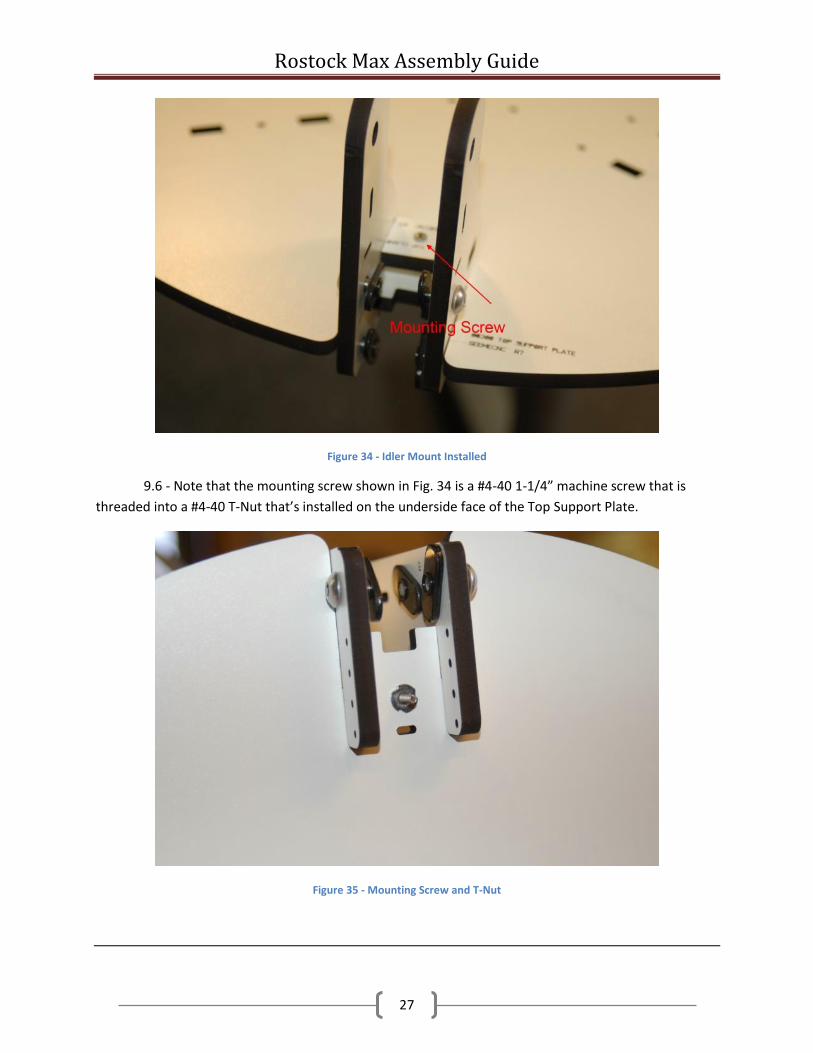
threaded into a #4-40 T-Nut that’s installed on the underside face of the Top Support Plate.
Figure 35 - Mounting Screw and T-Nut

Rostock Max Assembly Guide
28
10 – Installing the Top Support Plate
10.1 – Attach the Top Support Plate to the mounting rails. Finger tighten the button head
screws after you’ve got the Top Support Plate installed. The Idler Brackets get a final adjustment and
tightening later.
Figure 36 - Top Support Plate Installed
Rostock Max Assembly Guide
29
11 – Tighten the Rails at the Base
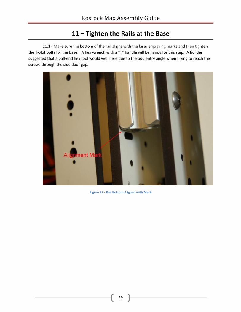
11.1 - Make sure the bottom of the rail aligns with the laser engraving marks and then tighten
the T-Slot bolts for the base. A hex wrench with a “T” handle will be handy for this step. A builder
suggested that a ball-end hex tool would well here due to the odd entry angle when trying to reach the
screws through the side door gap.
Figure 37 - Rail Bottom Aligned with Mark
Rostock Max Assembly Guide
30
12 – Adjusting the Top Support Plate
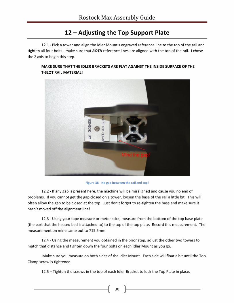
12.1 - Pick a tower and align the Idler Mount's engraved reference line to the top of the rail and
tighten all four bolts - make sure that BOTH reference lines are aligned with the top of the rail. I chose
the Z axis to begin this step.
MAKE SURE THAT THE IDLER BRACKETS ARE FLAT AGAINST THE INSIDE SURFACE OF THE
T-SLOT RAIL MATERIAL!
Figure 38 - No gap between the rail and top!
12.2 - If any gap is present here, the machine will be misaligned and cause you no end of
problems. If you cannot get the gap closed on a tower, loosen the base of the rail a little bit. This will
often allow the gap to be closed at the top. Just don’t forget to re-tighten the base and make sure it
hasn’t moved off the alignment line!
12.3 - Using your tape measure or meter stick, measure from the bottom of the top base plate
(the part that the heated bed is attached to) to the top of the top plate. Record this measurement. The
measurement on mine came out to 715.5mm
12.4 - Using the measurement you obtained in the prior step, adjust the other two towers to
match that distance and tighten down the four bolts on each Idler Mount as you go.
Make sure you measure on both sides of the Idler Mount. Each side will float a bit until the Top
Clamp screw is tightened.
12.5 – Tighten the screws in the top of each Idler Bracket to lock the Top Plate in place.

Rostock Max Assembly Guide
31
13 – Assembling the Filament Spool and Extruder Bracket
13.1 - The filament spool mounting bracket is made from two arms (Filament Spool Bracket P/N:
68392) attached to the Extruder Brackets (P/N: 68387) The three Extruder Support Spacers are also used
(P/N: 68388). Using your box cutter, pop out the countersink rings at the ends of the extruder brackets
and the filament spool brackets.
Figure 39 - Countersink Rings in the Extruder Brackets

Rostock Max Assembly Guide
32
13.2 - Attach the filament bracket and the Extruder Support Spacers as shown in Fig. 40.
Figure 40 - Filament Spool Bracket and Extruder Support Spacers
13.3 - Install Extruder Clamp (P/N: 68389) and then install the other half of the Extruder Support
Bracket & Filament Spool Bracket.
Figure 41 - Extruder Clamp & Extruder Support Bracket

Rostock Max Assembly Guide
33
13.4 - After assembly you can hang the extruder on the machine like so:
Figure 42 - Filament Spool & Extruder Support in the operating position.

Rostock Max Assembly Guide
34
13.5 – Install the Extruder Mounting Plate (P/N: 71534). The Extruder Mounting Plate attaches
to the Filament Spool & Extruder Bracket using four #6-32, 1” long flat head screws and four #6-32 nylon
lock nuts.
Figure 43 - Extruder Mount Installed
13.6 – Install the Bowden fitting to the Bowden Drive PTC adapter:
Figure 44 - Bowden fitting on Bowden Drive PTC Adapter
13.7 - Take care not to over-tighten the adapter – you want a good seal with the O-ring and
that’s it.

Rostock Max Assembly Guide
35
13.8 – Install Bowden Drive PTC Adapter on Extruder Mount Plate.
Figure 45 - Bowden Drive PTC Adapter Installed
Set this assembly aside for now – it won’t be needed for a while.

Rostock Max Assembly Guide
36
14 – Assembling the Extruder
14.1 – I’m going to cheat on this one and point you to the assembly video that PartDaddy (Steve)
published on YouTube - https://www.youtube.com/watch?v=mua3i_wP32I. He does an excellent job in
describing how the extruder is constructed. He designed it after all!
14.2 - I assembled mine using a vice with soft jaw covers to install the bearings in the gears as
well as install the drive gear on to the stepper motor. Please take care when installing that gear – you
need to ensure that you’re applying force straight down with no angular component or you’ll break the
gear or bend the stepper motor output shaft.
14.3 - I created a short video that describes some of the less clear elements of assembling the
extruder here: http://youtu.be/rAVlvRuHuE8.

Rostock Max Assembly Guide
37
15 – Building the Carriage
15.1 - Get three of the six short steel rods, the two platform halves (P/N: 68304) and six of the
CNC cut U-Joints (P/N: 68309).
Figure 46 - Platform Halves, U-Joints and U-Join Axles
15.2 - The first step is to assemble the platform halves and then start test fitting each of the U-
Joints.
Figure 47 - Test fitting the U-Joint

Rostock Max Assembly Guide
38
15.3 - The U-Joints will be tight. Take your file or sandpaper and clean up the sides where the U-
Joint makes contact. You want to remove enough material to loosen up the friction, but not introduce
any side-to-side play in the part. Do this for all six U-Joint locations.
You may want to insert one of the U-Joint axle rods to help get a feel on how much
force is needed to turn the U-Joint. Just remember, you don't want any side-to-side play in how the U-
Joint fits.
15.4 - Install U-Joints and the U-Joint axles (the steel rods)
Figure 48 - U-Joints and U-Joint Axles Installed.
15.5 - You can install these parts by either setting the U-Joints in place and then sliding the axles
in from the end, or put the U-Joint on the axle, set them into one half of the platform and then fit the
other platform half in place when you're done.

Rostock Max Assembly Guide
39
15.6 - Join the two platform halves using 12 #4 x 1/4" sheet metal screws.
Figure 49 - #4 x 1/4" Sheet Metal Screw
15.7 - Six screws are used on the top, six on the bottom. Use a P1 Philips screwdriver for this.
Take care not to over-tighten the screw or you could damage the screw holes - the plastic is pretty soft.
After you've got the screws in, work each U-Joint for a bit to make sure that it moves freely.
15.8 - If you have one that's very tight, loosen the screws on that side, withdraw the axle,
remove the U-Joint and file it down a bit more, carefully checking it before putting it back together.
Figure 50 - Screws Installed.
15.9 - Now you need to grab the six Parallel Delta Arms (P/N:68303) and "adjust" them.

Rostock Max Assembly Guide
40
15.10 - The arms have square corners, but they should have a radius to them. To do this, grab
a sheet of 100 grit sandpaper or a good file and sand the corners so they look like the photo below.
(sanded arm on the left, un-sanded on the right)
Figure 51 - Radius Sanded in Arm End.
15.11 - After sanding the radius, you'll want to remove the flashing on the ends of the arms
so that they'll grip the U-Joints about the same as you did on the platform. The idea is to just
reduce the friction, not make them loose in the joint.
15.12 - Now fit the delta arms to the U-Joints. Snap them on to the U-Joints that are attached to
the platform. Use a twisting motion to get them on there. They're tight, but they will fit.
Figure 52 - Arms Installed on the U-Joints

Rostock Max Assembly Guide
41
15.13 - Next, grab the Carriage U-Joint mounts, six CNC U-Joints, the package of #4 x 3/8" sheet
metal screws and the last three axle rods.
Figure 53 - Carriage U-Joint Mount Parts.
15.14 - You'll want to use the same sanding procedure as on the platform to ensure
that the U-Joints fit well in the mounts. However, you'll want to slide the U-Joint you're working with on
to an axle and use that to ensure proper alignment in the mount.
Figure 54 - Test Fitting the U-Joint
15.15 - You might want to complete step #16 and THEN sand the components - apparently
mounting the parts deforms the plastic a bit and may require further sanding after installation.

Rostock Max Assembly Guide
42
15.16 - Now it's time to mount the Carriage U-Joint mounts to the Arm Plates (P/N: 68344)
This requires six #6-32 Nylon lock nuts and six #6-32 x 5/8" Cap head screws.
Figure 55 - Carriage U-Joint Mounts and Arm Plates.
15.17 - Assemble each unit as shown in the picture, paying attention to how the Arm
Plate is oriented.
Figure 56 - Assembled Arm Plate

Rostock Max Assembly Guide
43
15.18 - Fit the U-Joint and their axles in the mounting plate. Note that the mount may be
gripping the U-Joint more tightly. File until it fits the same as before.
15.19 - Now lock the axles in place using the #4 sheet metal screws. Take care to examine how
the axle sits in the carriage grooves - you may need to file the sides a bit to get the axle to fully seat.
Figure 57 - Arm Plate with U-Joint Mount in Place.

Rostock Max Assembly Guide
44
16 – Assembling the Cheapskate Bearings
16.1 - For this step, you'll need the three Carriage Plates (P/N: 68343), the remaining CNC
machined aluminum hardware that was in the same bag with the U-Joints, the 608 bearings, and the
machined plastic bearing sleeves.
Figure 58 - Cheapskate Bearing Components
16.2 - Install the bearing sleeves on to the 608 bearings. Make sure to carefully de-burr the
plastic sleeves and remove any flashing from the rim of each one. Take care to not damage the outside
surface of the sleeves.
Figure 59 - Bearings with Acetal Sleeve Installed.

Rostock Max Assembly Guide
45
16.3 - Next we'll get the 3 Cheapskate bearings built. For this step you'll need the package of #6-
32, 2" machine screws, the #6 washers, the #6-32 x 1.75" cap head screws, the bag of #6-32 Nylon lock-
nuts, #4-40 x 1/2" socket head cap screws, #4 washers and #4 T-Nuts. Make sure when assembling the
Cheapskate that the text on the faces of the Melamine or Acrylic parts face the same direction. Note
that it may be easier to install the #4-40 T-Nuts for the next step at this stage. If you're using Acrylic,
you'll want to flatten the prongs on the T-Nuts. Insert two #6-32 machine screws with #6 washers in the
holes marked "SPACER" and install spacers on the other side.
Figure 60 - Bearing Spacers Installed.
16.4 - Install two bearings on to the spacers
Figure 61 - Bearings Installed.

Rostock Max Assembly Guide
46
16.5 - Now install two more spacers on the bearings.
Figure 62 - Last Spacers Installed
16.6 - Place the Carriage Plate on to the machine screws in the holes marked "SPACER"
Figure 63 - Carriage Plate Installed
16.7 - Install #6 washers and #6-32 nylon lock-nuts, finger tight
Figure 64 - Lock Nuts on Finger Tight.

Rostock Max Assembly Guide
47
16.8 - Attach belt clamp to the carriage. Install two #4-40 T-Nuts as shown
Figure 65 - T-Nuts Installed
16.9 - Next, fold the belt clamp in half as pictured.
Figure 66 - Folded Belt Clamp
16.20 -Install the belt clamp with two #4-40 cap head screws with the "open" end of the clamp
oriented as shown in the photo below.
Figure 67A & Figure 67B – Upper Belt Clamp Installed

Rostock Max Assembly Guide
48
16.21 - Install the other belt clamp as shown:
Figure 68 - Lower Belt Clamp Installed
16.22 - Prepare the Axle Supports (P/N: 68381) for installation. Insert a #6-32, 2" machine screw
and washer into the end of the axle support.
Figure 69 - Axle Support and bearing screw
16.23 - Next, install two spacers, a bearing and the opposite half of the axle support as shown -
finally install a #6 washer and #6-32 nylon lock nut (finger tight).
Figure 70 - Assembled Axle Support

Rostock Max Assembly Guide
49
16.25 - Insert a #6-32 nylon lock-nut into the base of each support as shown.
Figure 71 - Axle Support with Lock Nuts Installed
16.26 - Construct the other two Axle Supports the same as this unit.
16.27 - Install Cheapskate bearings on the rails. Orient the bearing as shown below:
Figure 72 - Cheapskate on Rail
16.28 - Take two eccentric cams and one bearing, assemble as shown:
Figure 73 - Bearing and Eccentric Spacers

Rostock Max Assembly Guide
50
16.29 - Install the bearings using a 2" #6-32 screw, 2 #6 washers and a #6-32 nylon lock nut as
pictured below. The screws go into the holes marked "ECAM". To make the installation easier,
make sure you've got the center holes in the eccentric cams lined up or the screw won't go in
easily.
Figure 74 - Eccentric cams & Bearings
16.30 - Do this for all three Cheapskate assemblies.
16.31 - Install Axle Supports. Installing the Axle supports requires 2 #6-32 1" flat head screws
each. You may need to lightly sand the Axle Supports in order to get them to fit. Do NOT force them -
you'll break the bearing assembly if you use too much force.
Figure 75 - Cheapskate with Axle Support Installed.
16.32 - Tighten it down! Tighten down the "fixed" bearing sets first - the ones without the
eccentric spacers. Now tighten down the eccentric bearing side, but not as tight as you did the fixed
side. You want it loose enough to move the eccentric spacers. While adjusting the eccentric spacers,
make sure you adjust on either side of the bearing equally.
16.33 - Adjust the top eccentric spacers "UP" (Facing the Cheapskate, rotate the eccentric
in a counter-clockwise fashion) until the bearing has a good grip on the T-Slot extrusion.

Rostock Max Assembly Guide
51
16.34 - Adjust the bottom eccentric spacers "DOWN" (Facing the Cheapskate, rotate the
eccentric in a clockwise fashion) until the bearing has a good grip on the T-Slot extrusion.
16.35 - You don't want the bearings gripping the rail too tightly - the Acetal bearing covers will
develop a flat spot overnight if you do. You want to adjust the side eccentrics to remove a lot of the
side-to-side "Wiggle". When you've got it where you want it, you can adjust the Axle Support assembly
to remove any remaining backlash and tighten down the screw holding the eccentric side in place.
Please make sure when adjusting the Axle Support screws that you tighten each one evenly so that the
bearing remains square to the rail.
16.36 -When you've got it adjusted, make sure you run the bearing up and down the rail a few
times, putting roughly 15-20lbs of pressure against it to wear in the Acetal a bit - you'll need to tweak
your adjustments after this process. (The video explains it pretty well about at the 1:38 mark)
Repeat this procedure for the other two Cheapskate bearings.
16.37 - Install the delta arms! Just like you did when mounting the arms on the platform U-
Joints, give the arms a little twist and they should snap right on. Make sure the U-Joints on the
Cheapskates still move freely before you install the arms. Fair warning, installing the arms is a bit like
wrestling an octopus. :)

Rostock Max Assembly Guide
52
17 – Idler Assembly
17.1 - Using the 9 remaining bearings, assemble the idler bearings using two idler spacers and a
608 bearing for each. See photo below:
Figure 76 - Idler Bearing
17.2 - Install two idler bearings at the bottom of each tower. Prepare six #6-32 1.75" socket
head cap screws with #6 washers. Install each idler pulley as shown in the photos below. Note that
your kit may include the same size Philips head screw instead of the cap head screw.
Figure 77 - Lower Idler Bearings Installed
17.3 - It may be easier to install the parts if you lay the Rostock Max down on its side. Note that
the "inner" idler bearing must be installed first or you won't be able to reach its location past the
"outer" idler bearing.

Rostock Max Assembly Guide
53
17.4 - Install one idler bearing at the top of each tower. The bearings are mounted in the slot in
the idler bracket as shown in the photo below.
Figure 78 - Upper Idler Bearing Installed
17.5 -Do not tighten down this idler yet - it's used later to correctly tension the drive belts.
Rostock Max Assembly Guide
54
18 – Installing the Belts!
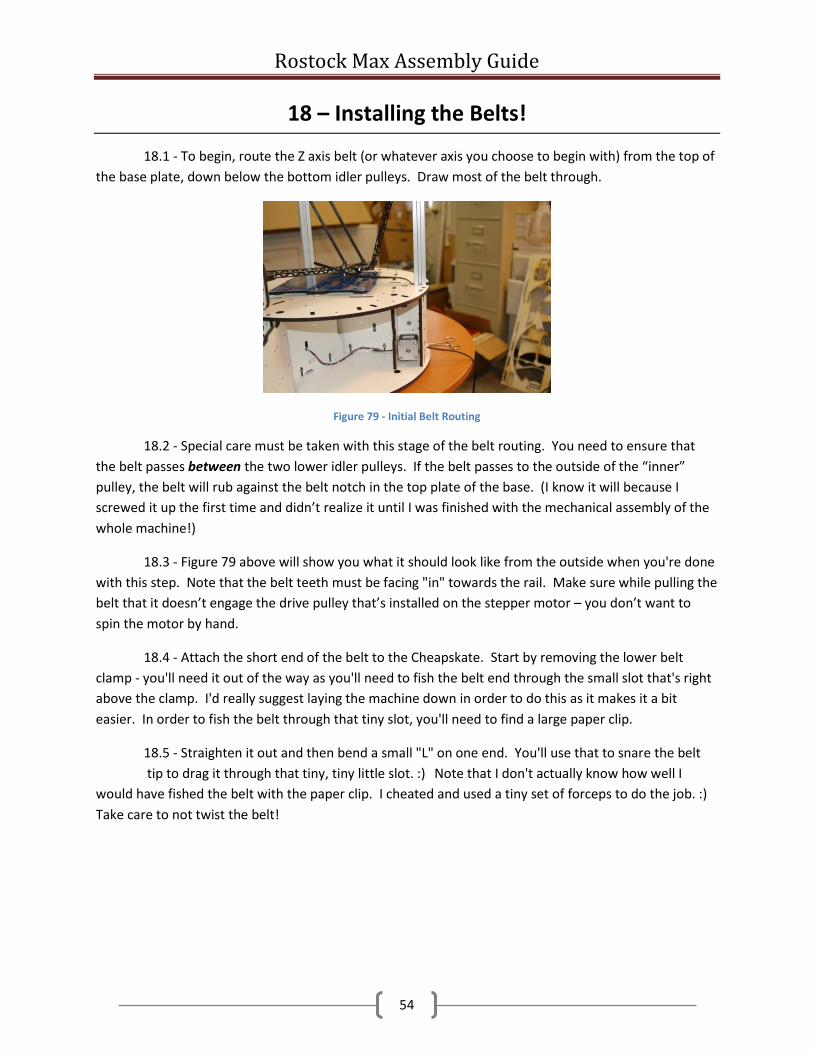
18.1 - To begin, route the Z axis belt (or whatever axis you choose to begin with) from the top of
the base plate, down below the bottom idler pulleys. Draw most of the belt through.
Figure 79 - Initial Belt Routing
18.2 - Special care must be taken with this stage of the belt routing. You need to ensure that
the belt passes between the two lower idler pulleys. If the belt passes to the outside of the “inner”
pulley, the belt will rub against the belt notch in the top plate of the base. (I know it will because I
screwed it up the first time and didn’t realize it until I was finished with the mechanical assembly of the
whole machine!)
18.3 - Figure 79 above will show you what it should look like from the outside when you're done
with this step. Note that the belt teeth must be facing "in" towards the rail. Make sure while pulling the
belt that it doesn’t engage the drive pulley that’s installed on the stepper motor – you don’t want to
spin the motor by hand.
18.4 - Attach the short end of the belt to the Cheapskate. Start by removing the lower belt
clamp - you'll need it out of the way as you'll need to fish the belt end through the small slot that's right
above the clamp. I'd really suggest laying the machine down in order to do this as it makes it a bit
easier. In order to fish the belt through that tiny slot, you'll need to find a large paper clip.
18.5 - Straighten it out and then bend a small "L" on one end. You'll use that to snare the belt
tip to drag it through that tiny, tiny little slot. :) Note that I don't actually know how well I
would have fished the belt with the paper clip. I cheated and used a tiny set of forceps to do the job. :)
Take care to not twist the belt!

Rostock Max Assembly Guide
55
18.6 - An alternate (and probably much easier method) is to insert the belt into the slot and drag
it down and around the idler pulleys. No matter what though, you're going to have to fish that sucker at
least three times when you attach the other end of the belt to the top.
Figure 80 - Belt inserted into Cheapskate
18.7 - Re-install the belt clamp with about 1/8" to 1/4" of belt extending below the clamp. Be
careful not to tighten the belt clamp too much or you'll split the clamp.
Figure 81 - Belt Clamp Installed

Rostock Max Assembly Guide
56
18.8 - Attach the long end of the belt to the Cheapskate. Remove the upper belt clamp and
route the belt up to the top idler, passing to the inside of the Cheapskate and fish that poor belt through
that tiny, tiny slot. Note that Fig. 82 shows the belt teeth facing away from the rail, this is an error! The
belt teeth should be facing IN towards the rail.
Figure 82 - Belt inserted in top of Cheapskate
18.9 - Once you've got the belt through the slot (make sure you don't twist it!) make sure that
the belt is actually on the toothed pulley at the bottom before you begin to install the belt clamp.
18.10 - Install the belt clamp - make sure that the top idler has fallen to the lowest position
before you tighten up the belt clamp - adjusting that idler is how we set the tension in the belt.
18.11 - I cannot emphasize enough how easy the forceps make this task! Before the next step,
you want to make sure that the toothed pulley on the stepper motors is properly aligned. See below for
an example of a properly aligned pulley.
Figure 83 - Properly Aligned Pulley with Belt Installed.

Rostock Max Assembly Guide
57
18.12 - Tighten Idler Bearings. Using a screwdriver as shown, raise the Idler bearing up until the
belt is tight and then tighten down the screw holding the idler bearing.
18.13 - Place the tip of the screwdriver on the other side of the rail and pry up gently. This
should raise the idler bearing up evenly. When the belt is tight, tighten the screw.
Figure 84 - Tensioning the Idler Pulley
Rostock Max Assembly Guide
58
19 – Installing the Limit Switches and Adjustment Screws
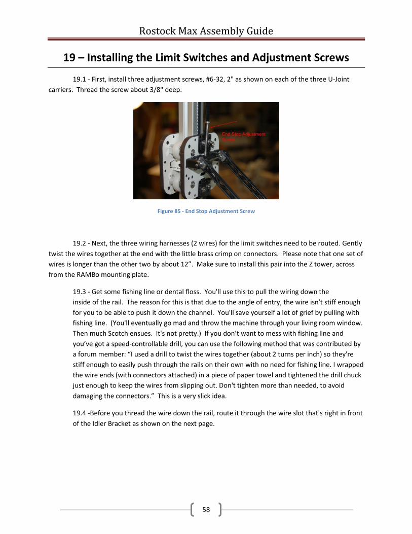
19.1 - First, install three adjustment screws, #6-32, 2" as shown on each of the three U-Joint
carriers. Thread the screw about 3/8" deep.
Figure 85 - End Stop Adjustment Screw
19.2 - Next, the three wiring harnesses (2 wires) for the limit switches need to be routed. Gently
twist the wires together at the end with the little brass crimp on connectors. Please note that one set of
wires is longer than the other two by about 12”. Make sure to install this pair into the Z tower, across
from the RAMBo mounting plate.
19.3 - Get some fishing line or dental floss. You'll use this to pull the wiring down the
inside of the rail. The reason for this is that due to the angle of entry, the wire isn't stiff enough
for you to be able to push it down the channel. You'll save yourself a lot of grief by pulling with
fishing line. (You'll eventually go mad and throw the machine through your living room window.
Then much Scotch ensues. It's not pretty.) If you don’t want to mess with fishing line and
you’ve got a speed-controllable drill, you can use the following method that was contributed by
a forum member: “I used a drill to twist the wires together (about 2 turns per inch) so they're
stiff enough to easily push through the rails on their own with no need for fishing line. I wrapped
the wire ends (with connectors attached) in a piece of paper towel and tightened the drill chuck
just enough to keep the wires from slipping out. Don't tighten more than needed, to avoid
damaging the connectors.” This is a very slick idea.
19.4 -Before you thread the wire down the rail, route it through the wire slot that's right in front
of the Idler Bracket as shown on the next page.

Rostock Max Assembly Guide
59
Figure 86 - Top End Stop Wire Slot
Figure 87 - Top End Stop wiring shown from the bottom.
19.5 - Next, you want to thread the wire around the side to the wire slot that’s in the Idler
Bracket as shown below.
Figure 88 - Wire slot in the Idler Bracket.

Rostock Max Assembly Guide
60
19.6 - Thread the wires down the central shaft of the extrusion using the fishing line - simply tie
a looped knot (a granny knot) around both wires just ahead of the crimp on connectors - make
sure you've twisted the wires together a bit as it makes pulling them both a bit easier. Thread
the fishing line down the tower and pull the extra out to the left side - that is the side that the
wire exit slot is on. When you're done, the top should look like this:
Figure 89 - Properly routed End Stop wiring.
19.7 - At the bottom of the tower, the wire should exit the rail as shown in Fig. 90.
Figure 90 - Wire exiting the tower rail.
19.8 - Make sure that the wires pass through the wiring slot to the left as shown above. Pull
wire on all three towers. We'll be coming back to them later, so don't attach the plastic connector shells
to them yet.

Rostock Max Assembly Guide
61
19.9 - There are three limit switches, one each for the three towers. Each switch is installed
using two #2-56 5/8" machine screws and two #2-56 nuts. The switches are wired as Normally Closed.
The end-stop wires should be attached to the "C" and "NC" terminals. In the photo below, these
terminals are on the left (C) and right (NC) of the switch.
Figure 91 - End Stop switch with connector lugs identified.
19.10 - Clip off the center terminal of the switch (marked "NO") and then bend the leads out as
shown in the photo.
Figure 92 - End Stop Switch with leads bent to clear the top.
19.11 -Bending the leads ensures that you'll be able to push on the spade lug connectors later
on. Please make sure that before you bend the leads on the switch that you’re bending them in
the correct direction! Do this by holding the switch so the Common leg is on the end closest to
the center of the machine. Raise the axis you’re going to install the switch on and bend the
leads such that when the switch is installed on one of the INSIDE faces of the Idler Bracket, the
End Stop Adjustment Screw will engage the end of the switch lever when it travels to the top.

Rostock Max Assembly Guide
62
19.12 - Install the switch wiring and using the #2-56 screws and nuts, install the switch as shown
in Fig. 93.
Figure 93 - End Stop Switch installed.
19.13 - Note that the position of my setup may differ from yours. Make sure the adjusting
screw will come in contact with the switch lever when the Cheapskate is at the top of its travel.
19.14 – Now you need to wire up the other end that connects to the RAMBo. Locate the three
pin locking connectors in the RAMBo wiring bag and six crimp-on connectors. You’re going to wire them
up such that pin #1 is the white wire and pin #2 is the black wire.
Figure 93-1 End Stop connector.
19.15 – The three end stop connectors belong in the “Max” row of the Endstops on the RAMBo.
Please refer to the connector illustration that came with the RAMBo for their location. DO NOT
CONNECT ANY WIRE TO THE “+” LEAD ON THE CONNECTOR. PERMANENT DAMAGE TO THE RAMBO
MAY OCCUR!

Rostock Max Assembly Guide
63
Congrats! The mechanical portion of the Rostock MAX Assembly Guide is complete. Next up is
all heaty-burny stuff and electronics.

Rostock Max Assembly Guide
64
20 –Wiring the Heated Bed
20.1 – For this task, you’ll need to remove the Heated Bed from the base and install the LED and
1k resistor as shown below. Make sure to orient the “flat spot” on the LED to the right. The flat area
marks the Cathode or “-“side of the LED. The 1k resistor limits the voltage in order to prevent the 12v
Heated Bed power from blowing the top off the LED.
Figure 94 - Power LED installed.
Note – if you’re unable to locate a T 1-3/4 LED, you can use any LED that has the same lead
spacing as a T 1-3/4. If you buy a LED that has the voltage drop resistor already installed (LEDs “rated”
at 12v will have this resistor built into them) you can just install a short piece of wire where the 1k
resistor would go.

Rostock Max Assembly Guide
65
20.2 – Mount the thermistor to the heated bed. Thread the thermistor leads through the holes
shown below and place a small amount of tape over the leads where they enter the Heated Bed. This
will help pin the leads in place so they can’t be bumped by something and short together. Apply a small
amount of RTV over the thermistor. This will affix it to the board and protect it. Flip the board over and
solder the leads in.
Figure 95 - Thermistor soldered & affixed in place.
20.2 – Now solder the two conductor white wires to the under –side of the heated bed where
it’s marked “V+” and “V-“. Before soldering the wires in, you may wish to intertwine them in order to
make the wires easier to manage.
Figure 96 - Thermistor wires intertwined for easy management.
20.3 – Now you’ll want to take the four conductor 18ga cable included in the kit and solder it to
the Heated Bed. Each pair of 12v terminals provide power to half the heating element on the board.
This is why four wires are required. Trim the wires back only about ¼” inch and insert them from under
the board. The colors I used were red/black for +/- on one pair, white/green for +/- on the second pair.

Rostock Max Assembly Guide
66
20.4 – Re-install the heated bed, routing the four conductor cable & thermistor cable though the
slot cut in the base as shown below. You may want to add a small piece of heat shrink tubing to neaten
the appearance of the wiring.
Figure 97 - Wires routed through the top
20.5 – Pull the four conductor cable through the bottom of the machine so it ends up in the
section where the RAMBo is located. Cut the cable long enough that you’ll be able to have the
electronics door completely open with the heated bed connector still plugged in. Install the connector
like shown in Fig. 98. Please make sure you wire it as shown if you followed my color guide above – if
you mix the polarities of the wires, you’ll either blow the fuse on the RAMBo or destroy it.
Figure 98 – Heated Bed power connector.

Rostock Max Assembly Guide
67
21 – Assembling, Wiring and Mounting the Hot End Assembly
21.1 – For this step, you’ll need all the components for the hot end. This includes the Hot End
Spacer (P/N: 68324), Hot End Adapter Plate (P/N: 68328), Bowden Hot End PTC Adapter (P/N: 68316),
Feed Tube Insulator, Heater Clamp, Nozzle (P/N: 71541), the Bowden Tube fitting, a thermistor, 2 power
resistors and finally, the Teflon Liner.
21.2 – The Hot End will come pre-assembled for the most part, but we’ll have to disassemble it a
bit to complete the assembly. First, remove the knurled nut on the Bowden Hot End PTC Adapter and
then slide the Hot End Adapter Plate & Hot End Spacer over the PTC Adapter. Replace the knurled nut,
just a bit more (and I mean a little bit more) than finger tight.
Figure 99 - Hot End Adapter Plate in position.
Figure 100 - Hot End Spacer and knurled nut in place.

Rostock Max Assembly Guide
68
21.3 – Next you’ll install the Bowden Fitting on the Bowden Hot End PTC Adapter by threading it
into the hole in the top. Tighten this down so it compresses the O-Ring seal, but not so much that it
starts to squish it out from under the brass fitting.
Figure 101 - Bowden Fitting installed on the Bowden Hot End PTC Adapter.
21.4 – Now remove the Nozzle from the Hot End and install the Teflon Liner. When replacing the
brass nozzle, you want to finger tighten it and then tighten it just a tiny bit more. You don’t want to
deform the liner inside the Hot End.
Figure 102 – The Teflon Liner ready for installation.
21.5 – In order for the RAMBo controller to determine what temperature the Hot End is at, it
uses a thermistor. The thermistor is shipped with bare leads, so the first thing we need to do is take
steps to prevent the leads from shorting out against one another.
21.6 – If you’ve got Kapton tape, you can create a “thermistor sandwich” that consists of a layer
of tape, the thermistor and another layer of tape. However, I didn’t have any Kapton so I’ll be
illustrating how I worked around the lack.

Rostock Max Assembly Guide
69
21.7 – I purchased some high-temperature silicone tape from the local auto parts store and
made a thermistor sandwich using that tape as well as a “mayo” layer of RTV.
Figure 103 - Thermistor sandwich with RTV sauce!
21.8 – The RTV takes about an hour to set up, so while the thermistorwich is cooking, let’s get
the power resistors prepared and installed in to the Hot End. You’ll want to cut a few strips of aluminum
foil just a little bit narrower than the resistor body is wide. You’ll need to wrap the resistor in foil in
order to get it to fight tightly in the milled holes that are in the Hot End. Please take special care to
make sure that any of the aluminum foil does not come into contact with the leads coming out of the
resistor. This can cause a short circuit and then we could bounce into a star and that would cut your trip
pretty short. Wouldn’t it, kid?
21.9 – Once you’ve got the resistors pressed into place, coat each end with RTV in order to seal
them to the Hot End.
21.10 – The thermistor is installed in one of the two small holes drilled perpendicular to the
resistor chambers on the Hot End. Fill one with RTV and press the thermistor in to place as shown
below. Make sure you’ve let the RTV cure at least one hour before moving on to the next step.
Figure 104 - Resistors & Thermistor sealed in with RTV.
Rostock Max Assembly Guide
70
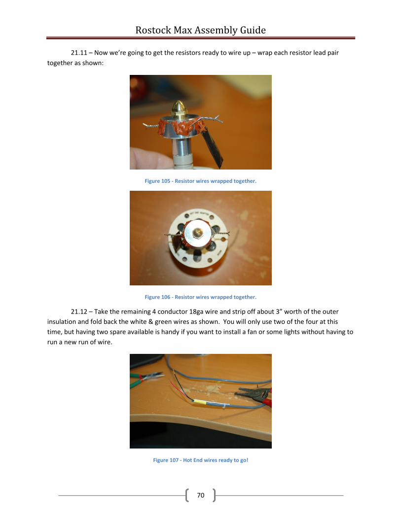
21.11 – Now we’re going to get the resistors ready to wire up – wrap each resistor lead pair
together as shown:
Figure 105 - Resistor wires wrapped together.
Figure 106 - Resistor wires wrapped together.
21.12 – Take the remaining 4 conductor 18ga wire and strip off about 3” worth of the outer
insulation and fold back the white & green wires as shown. You will only use two of the four at this
time, but having two spare available is handy if you want to install a fan or some lights without having to
run a new run of wire.
Figure 107 - Hot End wires ready to go!

Rostock Max Assembly Guide
71
21.13 – Trim off the “skirt” from two crimp-on wire nuts – this will help them clear in the limited
space available once the Hot End is mounted on the delta platform.
Figure 108 - Skirt trimmed from the crimp-on wire nut.
21.14 – Route the power wires through the Hot End Adapter Plate and crimp each one to a
resistor wire pair. Note that if you so choose, you can route the wires on the outside if you’ve trimmed
enough of the grey insulation back. This would give you a bit more room to work with when mounting
the Hot End.
Figure 109 - Power wires connected to the resistors.
Rostock Max Assembly Guide
72
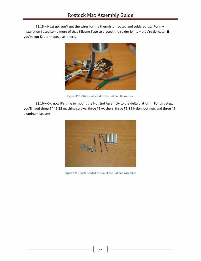
21.15 – Next up, you’ll get the wires for the thermistor routed and soldered up. For my
installation I used some more of that Silicone Tape to protect the solder joints – they’re delicate. If
you’ve got Kapton tape, use it here.
Figure 110 - Wires soldered to the Hot End thermistor.
21.16 – Ok, now it’s time to mount the Hot End Assembly to the delta platform. For this step,
you’ll need three 2” #6-32 machine screws, three #6 washers, three #6-32 Nylon lock nuts and three #6
aluminum spacers.
Figure 111 - Parts needed to mount the Hot End Assembly.

Rostock Max Assembly Guide
73
21.17 – Mounting the hot end is very simple, but take care not to damage the thermistor
installation. When you’ve got the Hot End Assembly mounted, inspect the wires coming out of the
resistors VERY carefully! You want to make sure that there’s no chance of the resistor leads coming in
contact with the Hot End itself. If you create a short circuit here, VERY VERY bad things will happen, up
to and including a fire, much running in circles, screaming and cursing.
Figure 112 - Hot End mounted in position.
Figure 113 - Hot End installed.
21.18 – Coil the wires up on the bed for the time being, we’ll be getting back to them soon.

Rostock Max Assembly Guide
74
22 – Wiring the Power Switch & RAMBo Power
22.1 – Take the included power switch and remove all the mounting hardware from it. The
mounting point is ¼” thick and there won’t be any room except the outside nut when it’s time to install
it.
22.2 – Cut one black wire and the green wire from the large 22 pin plug on the power supply.
Solder the black wire to the center lug on the switch and the green wire to one of the outside lugs –
make sure that the lugs you’re soldering to are in line. If you solder to one of the end lugs that are not
in line with the center lug, the circuit will not be completed when the switch is closed. I recommend
using heat shrink tubing to protect the exposed joints from shorting out against anything.
Figure 114 - Power Switch wired.
22.3 – Install the switch in the hole marked “Power” as shown. To orient the switch correctly,
rotate it so that the toggle is pointing down towards the green wire. If you draw an imaginary line along
the center of the toggle, it will “point” to the lug it’s in contact with. When in the “on” position, you
want it pointing to the green wire. Simple!
Figure 115 - Power switch installed.

Rostock Max Assembly Guide
75
22.4 – Now find the six pin connector that has three yellow and three black wires attached. Cut
the wires right off at the connector and route the wires into the electronics bay. Take the black six pin
terminal connector and attach the wires as shown. You only need to trim off about ¼” or so of
insulation. Note that the picture only shows one black and one yellow wire in the “Heater Bed”
positions. To get the most out of your power supply, it’s recommended that you put three yellow and
three black in the “Heater Bed” (the two terminals on the right) positions to get more power to the
heated bed. I recommend twisting three together and then soldering them to ensure good contact. (DO
NOT SOLDER THE BLACK AND THE YELLOW TOGETHER. MUCH SCREAMING AND FIRE MAY ENSUE.)
The reason for the additional wires is that you can only draw so much power through a wire of a
given gauge. Think of it like a small water hose. No matter how much you try to draw water through
that little hose, you’re only going to get as much as it has room for. However, if you use three small
hoses, you effectively get the same volume as if you had one hose with the same volume capacity as the
three smaller ones combined. The Phebe I bed doesn’t require all that much power, but the Onyx bed
does, simply because it’s nearly twice the area (and heating filament!) as the Phebe I.
Figure 116 - Power Block connector wired up.
22.5 – That’s all there is to it! When we get to the final connection step, this will plug into the
board on the connector shown in the photo above – it’s to the right of the large yellow component.
22.6 – Take some time now to bundle up the unused wiring coming out of the power supply
with some wire ties to keep it out of the way.

Rostock Max Assembly Guide
76
23 – Final Assembly!
23.1 – It’s final assembly time! The first thing up is getting the extruder installed on to the
extruder mount. As shipped, the extruder is designed to feed both 1.75mm and 3.0mm filament. This
set up is going to focus on the 1.75mm settings.
23.2 – Orient the extruder as shown in Fig. 117. You want to make sure the 1.75mm groove is
aligned with the Bowden fitting on the extruder mount.
Figure 117 - Extruder with 1.75mm drive highlighted.
23.3 – You want to install the extruder so that it aligns the 1.75mm drive groove with the
Bowden fitting on the mount. See below:
Figure 118 - Extruder correctly installed.

Rostock Max Assembly Guide
77
23.4 – Once you’ve got the extruder installed, go ahead and mount the Extruder Bracket
assembly as shown. If you haven’t already extended the leads for the drive stepper motor, now would
be a good time to do that. Please review the instructions in Section 4 for wiring details. The stepper
motor wiring can be routed as shown, or you can go around the outside of the door, through the finger
pull.
Figure 119 - Extruder mounted on the machine base.
23.5 – Install the Bowden Tube! This is a 4mm Teflon tube that goes between the Bowden
fitting on the Hot End and the Bowden fitting on the extruder mount. It just presses into place, but
make sure it’s fully seated.
Figure 120 - Bowden Tube installed.

Rostock Max Assembly Guide
78
23.6 – Tie the thermistor wire to the Hot End heater cable as shown below. I used waxed lacing
cord here because it won’t catch on the split tubing I’ll use to protect the wires with.
Figure 121 - Hot End heater and thermistor wires tied together.
23.7 – The wires supplied for the thermistors are not long enough to reach the RAMBo from the
Hot End. You’ll need to extend them at this time to make sure they’ll reach. Once you’ve done this,
route the thermistor and Hot End power wires into the electronics bay. Add a green, two position
terminal block to the Hot End wiring as shown:
Figure 122 - Hot End power connector.

Rostock Max Assembly Guide
79
23.8 – Install the split flex tubing on the wires leading to the Hot End and lightly bind it to the
Bowden tube using wire ties. Don’t over-tighten the wire ties as you’ll crush the split flex tubing.
Figure 123 - Split Flex Tubing installed on Hot End wiring.
23.9 – Now it’s time to hook it all up!
Figure 124 - RAMBo wiring illustration.

Rostock Max Assembly Guide
80
Use the RAMBo documentation as well as Fig. 124 to get all your connections made.
CONGRADULATIONS! You’ve got yourself a fully assembled Rostock MAX 3D Printer!
Kick back, relax and have your beverage of choice. After you’ve had a chance to recover from
your ordeal, we’ll get the necessary software installed and get the machine checked out in preparation
for your first print!

Rostock Max Assembly Guide
81
Software Installation and Configuration
Ok, you’ve managed to get this far, so it’s time to get this old beastie printing little green
squirrels (or whatever other “legitimate” use you have for this fancy thing).
The instructions provided in this guide are centered around the Windows operating system –
that’s because it is what I have. Details for Linux & MacOS should be on the Rostock MAX Wiki page.
In order to communicate with the RAMBo, you’ll need to download the driver for the board.
This driver is essentially just an INF file that Windows needs to figure out what’s going on with the new
peripheral you’ve just hooked up.
Download the USB Driver zip file from this location:
http://www.reprap.org/wiki/File:RAMBo_USBdriver.zip
Unzip the file to a temp directory or other place that you know the location of. For Windows
users (and likely XP, Windows 8 and Vista users as well), plug in the RAMBo and let Windows “fail” to
find the correct driver for the board. Open up the device manager by right-clicking on “Computer” or
“My Computer” and select “Properties” followed by “Device Manager”. Scroll down to the “Unknown
Devices” entry and right-click on the RAMBo entry. Choose “Update Driver” and then “Browse my
computer for driver software” (or something similar to this). Choose “Let me pick from a list of device
drivers on my computer”, then click the button for “Have Disk”. Browse to where you unzipped the file
you downloaded and then click “OK”. It may complain (depending on OS) that the driver isn’t signed –
allow it to install it anyway. That’s all there is to it. The RAMBo will now appear on your computer as a
standard serial port. On my computer it appeared as COM6 – it will most likely be different on yours.
If you need to make any changes to the firmware, you should head over to
http://www.arduino.cc and download the Arduino IDE.
The firmware for the Rostock MAX can be downloaded from this location:
https://github.com/johnoly99/Marlin-for-rostockmax-rambo. If you click on the “Zip” button on that
page, it will create a zip file of the current code and you can download it all in one go instead of picking
each file. I would recommend you download the firmware and unzip it so you can tweak it if need be.
For the initial check out of the printer, we’re going to use Repetier-Host which is commonly used
with the Rostock MAX. The software can be downloaded from http://repetier.com.
Run Repetier-Host and click on Config->Printer Settings. You’ll want to make sure that the
Connection tab looks like what is shown in Fig. 125. The Port: value for your computer will likely be
different.

Rostock Max Assembly Guide
82
Figure 125 - Connection configuration tab.
Where it says “Printer:” at the top of the window, enter in “Rostock MAX” or another name of
your choice and click the Apply button.
Next, click on the Printer Shape tab and change the settings there to those shown in Fig. 126.

Rostock Max Assembly Guide
83
Figure 126 - Printer Shape settings
After making the changes above, click “Apply” and then “OK”.
Now on to testing this sucker out – we first need to check and make sure that a) we can talk to
the RAMBo and that the end-stop switches are operating properly.
Click the Connect button on Repetier-Host – it’s right under the “File” menu item at the top.
Figure 127 - Connection Successful!

Rostock Max Assembly Guide
84
If you’ve selected the correct Port, you should see something along the lines of Fig. 127. If you
don’t and you’ve got a green light lit on the RAMBo, pick a different Port (Don’t forget to hit Apply!)
through the configuration screen and try it again.
Now that you’re connected, I want you to click on the “Manual Control” tab on the right side of
the Repetier-Host program. In the input field marked “G-Code:” I want you to type “M119” and press
the enter key.
In the log window you should see the text “x_max:L y_max:L z_max:L” This would indicate that
all three end-stop switches have not been pressed. If you see anything different, please check your
wiring! Now I want you to hold down the switch lever for the X axis and re-run the M119 command.
You should see the X_MAX value change to “H”. Do this for the Y and Z axes. This will ensure the end-
stop switches are function – this is very important for the next step.
If you haven’t powered on the Rostock MAX yet, please do so now. Ok, now you can climb out
from under the table. See, I told you it wouldn’t explode.
We’re now going to check the wiring of the stepper motors. You’re going to issue a “G28”
command which tells the machine to home all three axes against the end-stop switches. BEFORE you
issue the G28 command, please have your hand on the power switch. If the axes begin to travel
downward when you send G28, turn off the power immediately. Note that you should never try to
manually move the axes if the power is turned on – you could damage the machine. While moving an
axis with the machine powered off, do so slowly. A stepper motor can generate voltage when moved
too quickly and you run the risk of blowing a driver chip on the RAMBo. Take it slow!
If the axes all traveled up, great! If not, there are two ways to correct the problem (providing of
course the axes at least moved, even if in the wrong direction). The easy way (software!) and the hard
way (hardware!)
If you chose the hard way, rewire the misbehaving stepper motors to switch the positions of the
red and blue wires. Re-run the G28 homing test to make sure you’ve got it correct.
If you want to change the software, it’s pretty straightforward, but detailed step-by-step
instructions are a bit out of scope here. You essentially want to look for this block of code in
Configuration.h:
#define INVERT_X_DIR true // for Mendel set to false, for Orca set to true
#define INVERT_Y_DIR true // for Mendel set to true, for Orca set to false
#define INVERT_Z_DIR true // for Mendel set to false, for Orca set to true

Rostock Max Assembly Guide
85
For the axis that is going the wrong direction, change it to the opposite of whatever it currently
is shown in the file, recompile and upload the new firmware to the RAMBo. Note that you’ll have to
make sure you’re disconnected from the RAMBo in Repetier-Host or the Arduino IDE will not be able to
connect to the RAMBo for the update operation. Note that you should NEVER try to move the carriage
while the power is turned on! You don’t want to damage the motors or drive electronics. If you want to
move the platform around by hand, just turn off the power switch. You can leave the RAMBo plugged in
to the computer as it doesn’t power the stepper motors through the computer.

Rostock Max Assembly Guide
86
Calibrating Your Rostock MAX
Now that you’ve spent the last five minutes randomly positioning the axes, sending G28 and
then giggling like a school girl, why don’t we calibrate the Z axis? One thing I cannot stress enough, in
order for the calibration settings to be accurate, YOU MUST DO THEM WITH THE HOT END AND THE BED
AT OPERATING TEMPERATURE! For ABS this would be about 230C for the hot end and 70-100C for the
heated bed. PLA would be about 190C for the hot end and about 50-70C for the heated bed.
For this step you WILL need to have downloaded the Arduino IDE and the Rostock MAX
firmware source code.
If you haven’t done so already, install the included build plate on the heated bed using the
included binder clips. The plate only fits one way so it’s pretty easy to get it right. For the Phebe I
heated bed, you’ll use the 7” x 6.5” build plate. For the Onyx heated bed, you’ll use the included
280mm circular build plate.
Using the manual Z axis control in Repetier-Host, you are going to move the Z axis down until it’s
nearly touching the bed. Each time you click the tip of the down arrow, the Z axis should move 10mm.
In order to get it close to the bed, enter “G28” in the G-Code window to home the machine and then
enter “G1 Z50 F1200”. This should get you approximately 50mm from the build platform.
Once you’ve got the Z axis about a half-inch from the plate, place a sheet of notebook paper on
the build platform and start clicking the middle of the down arrow – this will move the platform down at
1mm per click. When you’re REALLY close to the paper, start moving it .1mm at a time (click the other
end of the down arrow for this). DO NOT ALLOW THE NOZZLE TO “CRASH” INTO THE BED!
Slide the paper back and forth a bit while moving down and stop as soon as the nozzle begins to
touch the paper and interfere with you sliding it back and forth.
If the Z axis reaches zero and still hasn’t touched the paper yet, increase the Z_HOME_POS by
10. The default for the Rostock MAX is 345.0. You can fine tune the Z axis by adjusting the end-stop
screws on each axis. Turning the screw “out” will decrease the height from the table, turning them “in”
will increase it. Think “Lefty, Lower”, “Righty, Raise”
Now that you’ve got the Z height set correctly, it’s time to make sure that each arm is moving
parallel to the table. Get a notepad and something to write with – this step needs notes. The
calibration locations I’ll be giving you will work with both the small Phebe I heated bed as well as the
Onyx heated bed.

Rostock Max Assembly Guide
87
Home the machine using G28 and then jog down to about 5mm using G1 Z5 F1200.
Using a caliper or other precise measuring tool (aka NOT your finger), measure the height from
the top of the platform to the print bed. This is your center measurement and this is the number you
want to get the next three measurements to match. Remember that every time you take a
measurement, you need to take it from the same spot on the carriage each time. If you don’t have a
caliper or don’t want to hassle with using this method, skip to the end of this section for a neat trick I
learned recently.
Figure 128 - Using the caliper depth probe to take the center measurement.
Now jog the platform towards the Z column by entering the G-Code “G1 Z5 Y110 F1200”. You
want to position the arm so it’s nearly parallel with the Z tower. Don’t be surprised if you find yourself
turning the screwdriver in such tiny amounts you can hardly notice the screw move.
Figure 129 - Carriage positioned close to the Z axis tower.

Rostock Max Assembly Guide
88
If the measurement you get at that point is higher than at the center, you’ll want to turn the
adjustment screw UP (out) a quarter turn or so and then in the G-Code command field, “G1 Z5 Y110
F1200”. This will position the platform in the exact same spot as it was in for your first measurement.
Repeat this process until the Z tower measurement matches the center measurement as closely as you
can get it. The closer you are to that center measurement, the better and more consistent your print
results will be.
On to the Y tower!
Figure 130 - Carriage positioned next to the Y axis tower.
The first thing you’ll notice about the photo above is that the arms aren’t nearly as close to the
tower as we got for the Z axis. This is because we need to be able to still touch the build platform and
it’s as close as it can get and still have room for the depth probe on the caliper to still hit the bed from
our measuring point.
To position the carriage next to the Y tower, enter the G-Code “G1 Z5 X70 Y-30 F1200”. Repeat
the steps taken to align the Z tower for the Y tower.

Rostock Max Assembly Guide
89
Finally, let’s do the X tower.
Figure 131 - Carriage positioned next to the X axis tower.
The process is the same as for the other two towers. Enter the G-Code “G1 Z5 X-70 Y-30 F1200”
to send the carriage to the measurement point for the X tower. Don’t forget, each time you adjust the
end stop screw, you MUST enter the G-Code “G28” in order to re-home the machine so that your next
measurement will reflect the change you made to the adjustment screw!
You should now have your Rostock MAX calibrated! The great thing about the Rostock MAX and
delta designs in general is that once you’ve got it calibrated, you never need to touch it again unless you
change the thickness of the build plate! None of this “leveling the bed” crap that those poor Cartesian
printer users have to deal with. Set it and forget it!
Now that you’ve run the axes around for a while, I want you to re-check each Cheapskate
bearing to make sure it’s still got a good grip on the rail it’s attached to. You’ll want to do this
periodically as time goes on in order to compensate for the gradual wear that will happen over time as
you use your Rostock MAX printer.
If you don’t have a caliper or didn’t want to mess with my method of doing the calibration,
you’re in luck! I recently learned about a very slick method of easily calibrating your machine.
You’ll do very much the same as above, but your tower points are now:
Z Tower – X0 Y90
Y Tower – X63 Y-30
X Tower – X-78 Y-48

Rostock Max Assembly Guide
90
Go to the base if each tower with a Z0 height – keep a sheet of paper between the head and the
bed. You’ll adjust each tower so that the paper just begins to grab the tip of the nozzle. When you’ve
done this for all three axes, you should be perfectly calibrated! Many thanks to the person that wrote
up this procedure at http://minow.blogspot.com.au/!
Another important ongoing maintenance task is to ensure that the knurled nut holding the Hot
End together remains tight. Before you heat up the Hot End for the first time each day, please take the
time to ensure that the nut is tight. Heating and cooling cycles can loosen it over time.
Figure 132 - Tighten me!
Not keeping an eye on that nut can ruin prints and if left un-noticed long enough could even
damage the wiring on the Hot End. I’ll give you a perfect example. When running my second part, the
nut began to loosen. The hot end rotated a bit and the resistor wires came in contact with the hot end.
This blew the 5A micro fuse for the MOSFET outputs on the RAMBo. Because of how the board is
oriented in my installation, I didn’t notice there was a second fuse. The MOSFET fuse is right below the
large yellow component, right next to the primary power connector. 12 hours later, after much poking
prodding, hair pulling and yelling, that fuse was found and tested. If you don’t have a replacement, a
quick & dirty field repair can be made by carefully soldering two 28ga wires to the top of the burned out
fuse. Solder those wires to a small, blade-type 5A automotive fuse. You’ll be back in business long
enough for the proper replacement to arrive. Don’t throw your fix away either, it could come in handy
in the future!
The last step we’re going to do involves “tuning” the PID algorithm in the firmware PID is an
acronym that stands for Proportional-Integral-Derivative and it defines a generic feedback mechanism
that’s used in a number of industrial control applications.
The Rostock MAX firmware contains a feature call “PID Autotune”. This feature will help
improve the accuracy of the hot end temperature management, which is very important.

Rostock Max Assembly Guide
91
Before you can start the PID Autotune routine, the hot end must be at room temperature. Once
it is, enter M303 S200 in the G-Code window and press enter. The log section of the screen should
display “PID Autotune start”. The routine takes about 10 minutes to complete and while it runs you’ll
see data displayed in the log screen, similar to the example below:
08:51:17.390 : PID Autotune start
08:55:37.640 : bias: 72 d: 72 min: 198.16 max: 206.47
08:56:32.945 : bias: 67 d: 67 min: 197.83 max: 203.48
08:57:24.730 : bias: 65 d: 65 min: 198.13 max: 202.68
08:57:24.735 : Ku: 36.35 Tu: 51.77
As the autotune routine runs, it will periodically print out a set of values labeled Kp, Ki, and Kd.
Write these values down as they appear. When the autotune routine completes, average all the values
together. For example, my PID Autotune routine just returned three Kp values: 21.81, 22.41 and 22.35.
The average of those three is 22.19. When you’ve got the average figure for all three of the PID values,
open up the Arduino IDE and edit the file “Configuration.h”. Search for “DEFAULT_Kd” You’ll want to
change that figure and the DEFAULT_Ki and DEFAULT_Kd values to match the averages you came up
with from the PID Autotune output. Save your changes and upload the firmware to the board.

Rostock Max Assembly Guide
92
Your First Print with the Rostock MAX
Here’s where the rubber meets the road! The whole point of the previous 85 pages was to get
to this point. It’s important to note that the version of Slic3r used for this manual is 0.9.7.
The first object we’re going to print is a 3D printing favorite, the Skeinforge Bridge Calibration
Cube!
Go here: http://www.thingiverse.com/download:15293 to download the STL file for the cube.
We’ll be feeding this to Slic3r to print!
Before you can print the cube, you’ll need to adjust some settings in Slic3r. Slic3r is a special
program that will take a solid model file (STL) and “slice” it into many thin layers so the Rostock MAX can
print it.

Rostock Max Assembly Guide
93
Click on the Slicer tab in Repetier-Host and then click on the Configure button to the right.
Figure 133 - The Slic3r configuration screen.
You should see a window similar to Fig. 133 show up. The first tab, Plater isn’t going to be used
for this tutorial, but I recommend you investigate it later.
Click on the Print Settings tab – this is where we’ll set up some important settings that pertain
to this specific print.
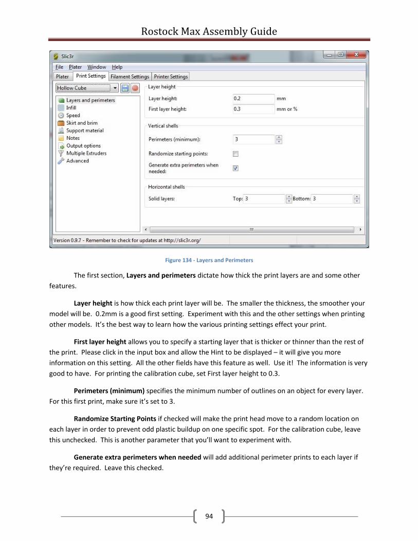
Rostock Max Assembly Guide
94
Figure 134 - Layers and Perimeters
The first section, Layers and perimeters dictate how thick the print layers are and some other
features.
Layer height is how thick each print layer will be. The smaller the thickness, the smoother your
model will be. 0.2mm is a good first setting. Experiment with this and the other settings when printing
other models. It’s the best way to learn how the various printing settings effect your print.
First layer height allows you to specify a starting layer that is thicker or thinner than the rest of
the print. Please click in the input box and allow the Hint to be displayed – it will give you more
information on this setting. All the other fields have this feature as well. Use it! The information is very
good to have. For printing the calibration cube, set First layer height to 0.3.
Perimeters (minimum) specifies the minimum number of outlines on an object for every layer.
For this first print, make sure it’s set to 3.
Randomize Starting Points if checked will make the print head move to a random location on
each layer in order to prevent odd plastic buildup on one specific spot. For the calibration cube, leave
this unchecked. This is another parameter that you’ll want to experiment with.
Generate extra perimeters when needed will add additional perimeter prints to each layer if
they’re required. Leave this checked.

Rostock Max Assembly Guide
95
Solid Layers determines the number of solid or 100% fill layers that should be done on the top
and the bottom of the print. For the calibration cube, set this value to 5. Higher values may give better
print results on the top.
Click the floppy disk icon next to the drop-down and name the print settings “Calibration Cube”
and then click on Infill.
Figure 135 - Infill
The Infill configuration page controls how the interior, solid areas of your model are filled up
with plastic.
Fill density controls how much plastic is used to fill the “solid” areas of your model. This is a
percentage value, so 0.2 shown above will be a 20% infill.
Fill pattern determines HOW the fill is added to the solid areas of your model. It provides for a
number of different fill patterns, but for this first print make sure it’s set to rectilinear.
Top/Bottom fill pattern is essentially the same as Fill pattern, but the fill density is 100%. For
this first print, make sure it’s set to rectilinear.
Infill every allows you to change how the infill works if you don’t want it to infill plastic on the
solid areas for every layer. For the test cube, set this to 1.

Rostock Max Assembly Guide
96
Solid infill every allows you to force a 100% infill every so many layers. For the test cube, set
this to 0.
Solid infill threshold area will force a 100% infill for sections that have a size less than or equal
to the size specified. Note that the value is expressed in square millimeters. For our test cube, set this
to 5.
Only retract when crossing perimeters means that the filament will only be retracted from the
print head when you’re crossing perimeters of the part and you don’t want to risk any “extra” plastic
accumulating outside the print volume. The infill areas really don’t matter and not retracting while
crossing these areas will improve your print speed. For the test print, check this option.
Click the save icon (don’t change the name!) and let’s move on to Speed!
Figure 136 - Speed
Each option above controls the speed in which the print head will move during the various
stages of the print process. For your first print, make sure your settings match all those above. If you’re
curious about what each one effects, hover your mouse pointer over the field you’re interested in. A
helpful hint will be displayed with a short description of the field.
When you’re done, click the save button and let’s move on to the next section, Skirt and Brim.

Rostock Max Assembly Guide
97
Figure 137 - Skirt and Brim
The Skirt page has some very useful options on it that are useful for starting the printing
process.
Loops does exactly that. Before your part starts to print, the printer will print a number of loops
around where your part will print. This is very handy when you’d like to make sure that the hot-end is
primed with enough plastic to begin the printing process. For the calibration cube, set this to 3.
Distance from object dictates how far away from where your part will be that the loop will
print. Set this to 3mm for the cube print.
Skirt height will tell the looping routine in Slic3r how high to build a “skirt” around your part.
This is especially useful if you want to use the looping feature to build a “draft dam” around your part to
prevent air drafts from causing adhesion or other problems. Specify a high number here (20?) to build a
skirt around your part. For now, set this to 0. This is really only a useful feature if you’ve got issues with
cold air movement or you’re using a Cartesian printer than moves the build platform around quickly.
Brim width tells Slic3r to print what essentially amounts to a hat brim around your part for the
distance specified. This can be helpful for prints that have problems with curling edges. Let’s leave this
value set to zero – we’re more interested in getting a good overall print than worrying about curling
issues right now.

Rostock Max Assembly Guide
98
Figure 138 - Support Material
The Support Material page covers options that are specific to parts that have large overhangs
that could make printing problematic. These settings would craft little support structures as part of the
printing process that you would cut away after printing finishes. Their purpose is to support extruded
plastic that sticks out in “open” air at angles greater than 45 degrees and wouldn’t stand up well during
printing. For our calibration cube, there’s nothing to set here, so leave “Generate support material”
unchecked.

Rostock Max Assembly Guide
99
The Notes page is very straightforward. If you have any comments you’d like to include with the
G-Code that Slic3r generates, put it here!
Figure 139 – Notes

Rostock Max Assembly Guide
100
The Output Options page covers three main items that handle some details on how the G-Code
is generated for your part.
Figure 140 - Output Options
Complete individual objects will tell Slic3r that if you’re printing multiple parts during one job
that you want each part to print before Slic3r begins printing the next part. For the calibration cube
we’ll leave this unchecked.
Extruder clearance (mm) tells Slic3r the amount of free space it needs to leave around each of
the objects in order to avoid striking a previously printed object with the extruder.
Verbose G-Code indicates that you want Slic3r to put descriptive text on each line in the G-Code
file. This can be a good educational tool to see what each G-Code statement does, but will create pretty
large files – if you’re printing from an SD card, you may want to leave this unchecked. For your first
print, you can check this or not. It’s entirely up to you. When it’s time to print, I’ll show you where you
can view the code that Slic3r generated and you can see (or not!) the comments it put in.
Output filename format allows you to change how the filename is created for your print job.
For now, just leave it at the default shown.

Rostock Max Assembly Guide
101
Figure 141 - Multiple Extruders
The Multiple Extruders page allows you to specify a specific extruder for each of the tasks listed.
For now, leave them all set to 1. Note that unless your Rostock MAX has more than one extruder
mounted on the carriage, you’ll never need to revisit this configuration page.
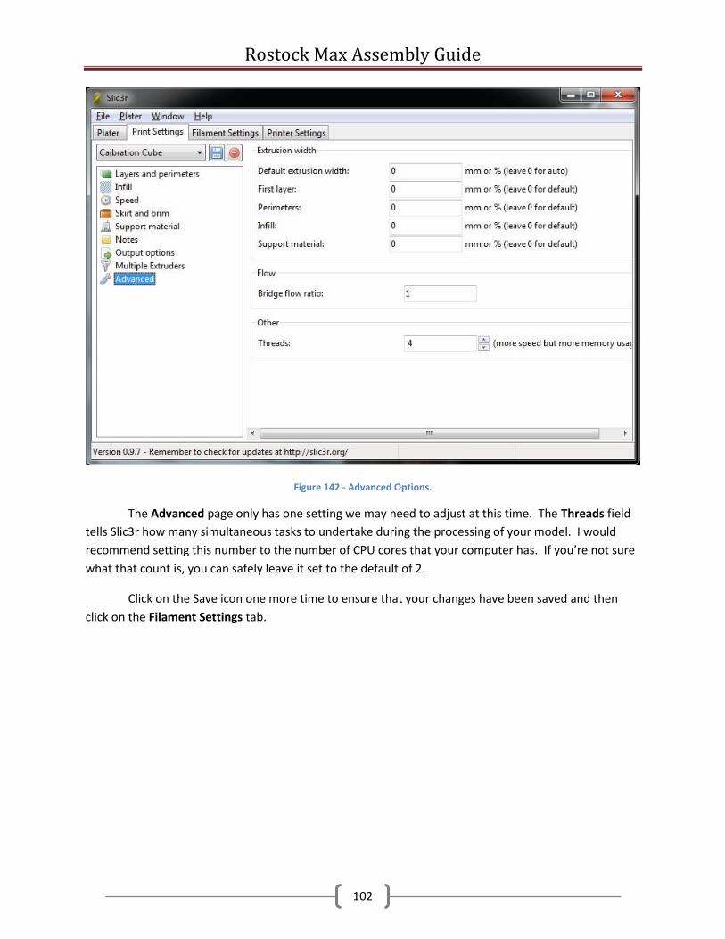
Rostock Max Assembly Guide
102
Figure 142 - Advanced Options.
The Advanced page only has one setting we may need to adjust at this time. The Threads field
tells Slic3r how many simultaneous tasks to undertake during the processing of your model. I would
recommend setting this number to the number of CPU cores that your computer has. If you’re not sure
what that count is, you can safely leave it set to the default of 2.
Click on the Save icon one more time to ensure that your changes have been saved and then
click on the Filament Settings tab.

Rostock Max Assembly Guide
103
The Filament Settings tab is for setting options that are relevant to the filament that you’re
going to use on your test print.
Figure 143 – Filament
For the Diameter setting, you’ll want to use your digital calipers to take a few test
measurements along some length of filament to get an idea of its actual diameter. Put an average of
the measurements you took into the Diameter field.
Extrusion Multiplier proportionally changes the flow rate of the extruder. For your test print,
make sure this is set to 1 as shown.
The temperature settings shown in Fig. 143 are good for your first test print, assuming you’re
using ABS plastic. If you’re using PLA or another material, you should consult your filament vendor for
appropriate extruder and heated bed settings.
Click the save icon at this point and name the configuration something that makes sense to you.
I use the vendor name, the color, type and filament diameter. You really want a configuration file for
every color, vendor and type of filament you print as not all filament is created the same, even from the
same vendor.

Rostock Max Assembly Guide
104
The last filament page is Cooling. This is primarily used by people extruding PLA. Make sure
Enable Cooling is unchecked, save your changes one more time and we’ll move on to Printer Settings.
Figure 144 - Cooling.

Rostock Max Assembly Guide
105
On the Printer Settings tab in the General page you’ll see how you specify the physical
attributes of your Rostock MAX 3D printer. Make sure your Slic3r settings match those in Fig. 145 and
then click the save icon. Name it “Rostock MAX” and then click on the Custom G-Code page.
Figure 145 - General printer settings.

Rostock Max Assembly Guide
106
Figure 146 - Custom G-Code
The Custom G-Code page allows you to tell your Rostock MAX to do some specific chores before
and after a print job is run.
Start G-Code is run before the print job is run. In this case, we send G28 which re-homes the
Rostock MAX, followed by G1 Z300 F7500 which rapidly moves the carriage to 300mm above the print
surface.
End G-Code is executed right after the print job is finished. M104 S0 turns off the heat to the
extruder and M140 S0 turns off the heat to the heated bed. G28 re-homes the machine.
Layer Change G-Code would insert any special code you need between each layer that’s printed.
For your first test print, make sure your Slic3R configuration matches what’s shown above in Fig.
146. Click save and let’s move on to the Extruder 1 page.

Rostock Max Assembly Guide
107
Figure 147 - Extruder Settings
Size describes the diameter of the hole in your extruder nozzle. For a typical Rostock MAX, this
should be 0.5mm. This helps Slic3r know how much plastic is extruded for a given extrusion speed.
Extruder Offset is only used if you’ve got multiple extruder nozzles. For now, leave both X and Y
set to 0.
Retraction Length tells Slic3r how much filament should be “backed out” of the hot end when
making rapid moves. This helps ensure that no plastic is accidentally extruded while the hot end is
moving to a new position to begin printing again.
Lift Z will tell the machine to rapidly move the Z axis up this amount during retractions. For the
calibration cube, leave this set to 0.
Speed will tell Slic3r how fast the plastic should be fed to the hot end. For this and most other
prints, you’ll want to set it to 55.
Extra length on restart will extrude an extra amount of filament once a rapid move & retraction
has occurred. This is seldom used. Set it to 0.

Rostock Max Assembly Guide
108
Minimum travel after retraction will tell Slic3r that you have to move at least as far as specified
here for a retraction to take place during a rapid move. Set this to 3 for the calibration (and most other)
cube prints.
You can leave the Retraction when tool is disabled advanced settings at their defaults as they
really only pertain to multiple-extruder jobs.
Now make sure you click save and then close the Slic3r configuration window.
In order to give Slic3r something to work with, we need to load a model into Repetier-Host.
Click the Load button and navigate to where you saved the hollow_cube.stl file. When you open the
file, you should see a rendering of the cube sitting in the center of your build volume as shown below.
Figure 148 - Hollow Cube loaded!

Rostock Max Assembly Guide
109
Now it’s time to tell Slic3r to do its thing. Click on the Slicer tab and then click the Slice with
Slic3r button. After a few seconds, you should have a display that looks very much like this:
Figure 149 - Sliced and ready to go!

Rostock Max Assembly Guide
110
The cyan colored line you see is the path that the extruder head will take as it moves and the
dark blue represents the extruded plastic. You can click in that window an using your mouse, pan, zoom
and rotate the model. In fact, why don’t you zoom in on the calibration cube so you can see what it will
look like:
Figure 150 - Visible tool path.
The rendering in Fig. 150 is a pretty accurate rendition of what will happen on your print bed.
Notice the three rings around the part? When you set Loops to 3, it caused that to be generated as part
of the tool path. (“tool path” is a term used to describe the path that the tool takes during the entire
printing process)

Rostock Max Assembly Guide
111
Back when I was walking you through the Slic3r configuration, I mentioned we’d be viewing the
G-Code that Slic3r generates. Fig. 151 below shows the code.
Figure 151 - G-Code for the calibration cube.
All that text is what controls the Rostock MAX through the RAMBo. Repetier-Host sends each
line of that file to the RAMBo board and the software on the board interprets each line in order to tell
the Rostock MAX to move to a specific place, extrude plastic, etc. Lines that start with “;” are

Rostock Max Assembly Guide
112
comments. They’re ignored by the G-Code processor on the RAMBo board and you’ll notice that the
start of the file contains all the settings that you set up in Slic3r. This is a great way to track prior
configurations.
If you want to know what a specific program code does, you can click on the Help tab under the
editor and each time you click on a line of code, Repetier-Host will display a little bit about what it does
if It knows about it. There are very few codes that Repetier-Host doesn’t know about.
I highly recommend learning more about how G-Code works – that knowledge will help you get
the most out of your Rostock MAX in the long run.
Now before can print the model you just sliced, we need to load filament into the printer! If you
haven’t already, mount the spool of ABS on the spool holder and then begin heating the extruder by
clicking on the Heat Extruder button. Make sure the temperature is set to 240 (for ABS – for PLA use
190).
Figure 152 - Loading the filament into the extruder drive.
The simplest and most trouble-free method of loading filament into the extruder drive is to
loosen the two tension screws shown in Fig. 152. You want them loose enough that you can pass the
filament between the hobbed drive rollers pretty easily. Thread the filament into the Bowden tube
entrance until you see a couple of inches of filament showing in the Bowden tube. I came to this
procedure by trial and error, mostly error. In trying to get the extruder to do the loading for me, I found
that it would most often not hit the entry to the Bowden tube squarely and would start shoving filament
through the space between the drive rollers and the Bowden tube entry. Makes a hell of a mess!
Once you have the filament loaded, tighten down the tension screws such that they’re
compressing the O-ring spacers a small amount. This will give you a good amount of tension to start
with. We’ll adjust that if needed in a sec.

Rostock Max Assembly Guide
113
Figure 153 - Filament loaded correctly in the Bowden tube.
Now that you’ve got the filament properly loaded, I want you to make sure the machine is in its
home position by entering G28 in the G-Code window, followed by G1 Z5 F1200. This will help the
filament load into the hot end by making the Bowden tube as parallel as possible to the hot end. This
will help prevent loading jams.
Once the hot end is in position, I want you to set the extruder temperature to 240 (for ABS, 190
for PLA) and click on the Heat Extruder button. The next step requires using the extruder drive, and
safety interlocks prevent it from functioning if the hot end is not at operating temperature.
After the hot end is at temperature, you’re going to use the manual extruder controls to feed
filament into the hot end.
Figure 154 - Controlling the extruder drive manually.
Set the extruder controls as shown above. The down pointing arrow feeds filament into the hot
end and the up arrow retracts it. Go ahead and click on the up arrow. Continue to click the button (only
click it once – wait for the extruder to stop before you click it again!) until the extrusion is about an inch
from the hot end. While the filament is loading, I want you to pinch the filament as it enters the
extruder drive. If you have the tension set correctly you shouldn’t be able to stop the filament by
pinching it with two fingers. If you CAN stop it, tighten each tension screw about a half-turn until you’re
unable to stop the filament. Please make sure that you tighten each screw evenly!

Rostock Max Assembly Guide
114
Now that you’ve got the drive tension set properly, click the down arrow again and get the
filament to enter the hot end. It may take a click or two, but you should see filament coming out of the
nozzle shortly after you see the end of the filament enter the top of the hot end. Once the filament is
extruding, I want you to enter G1 Z300 F1200 to bring the platform up close to the top and then click
then down button to extrude at least another 300mm through the hot end. When the extruder motor
stops for the final time, go ahead and turn off the heat to the hot end. (..and clean up the mess of thin
plastic that’s now all over the build platform!)
I would recommend that before each print, it’s a good idea to extrude about 20-25mm of
filament before you begin. That would ensure that the extruder is primed and you don’t have any jams.
Ok, I give up. I can’t keep you waiting any longer. Reach up with your mouse cursor and whack
the Run Job button!
When you start the job, Repetier-Host will start sending the G-Code in the editor to the RAMBo
over the USB cable. The first thing it will do is begin to heat the bed. When the bed has reached its
operating temperature, it will then begin heating the hot-end. Once the hot end has come up to
temperature, the Rostock MAX will begin printing the calibration cube you just sliced.
Before the printer begins, I want you to move the Feedrate slider that’s in the Speed Multiply
box back to about 50.
The reason for this is to help make sure that the print is going to adhere to the bed properly and
to ensure that the flow rate will be sufficient for the printing speed. If you go too fast, you can easily
over-run the ability of the hot end to melt the plastic. When that happens, the hot end will jam and the
extruder will begin shoving plastic out the side, between the face of the Bowden tube and the extrusion
drive rollers. It’s not a pretty sight and I’ve done it more times than I care to think about while learning
how to use a 3D printer.
Now that being said, there’s no reason you can’t bump the speed up just to see how well it
does. The worst that can happen at this point is you jam the extruder. You’ll do that often enough so
you might as well figure out how to clear it now.
I’ll shut up now so you can watch your Rostock MAX in peace. It’s absolutely the most
fascinating thing you’ll watch in a long time.

Rostock Max Assembly Guide
115
Fail Happens. (to everyone!)
You will find over time that 3D printing can be very rewarding and simultaneously the most
frustrating thing you’ve ever done. You’ll quickly learn the new natural law that has come into effect in
the last few years. 3D Printers Are Total Jerks. It’s just the nature of the beast – when you’re on the
bleeding edge of technology, you ARE going to get paper-cuts as part of your learning curve.
Let’s take a look at some of the mistakes that I made while writing this manual and learning
about 3D printing as I did it.
Figure 155 - Too fast, not enough plastic.
Above is my first “official” print. This is the calibration cube that you’re either already printing,
or will soon print from my example above.
There are a couple of things going on here – first of all you’ll notice how ratty it looks. This is a
very obvious symptom of inadequate material flow as a result of either too slow an extrusion rate, too
fast a printing speed or insufficient hot end temperature. Sometimes it’s hard to learn how to go slow
when all you really want to do is firewall the throttles and scream like a little kid.
I stopped the print in Fig. 155 and started over.

Rostock Max Assembly Guide
116
Figure 156 - Too fast, then slowed it down!
This time I started slowing it down using the Feedrate multiplier slider. The good print you see
above the rotted portion was done at the 60% I recommended in the previous section.
Figure 157 - Stretchlet, too fast.
Now this is an interesting result – it’s the same flow issue but there’s a deeper reason for it than
what you’d think. You see this is the second stretchlet I printed. The first one printed perfectly and with
the Feedrate multiplier slid all the way over to 300%!
The knurled nut loosened on my hot end during another print I was doing and that resulted in a
short that blew the MOSFET fuse on the RAMBo and may have damaged the thermistor. This damage
may have done a number on the thermistor and caused it to over-report the temperature. This would

Rostock Max Assembly Guide
117
result in the absolutely INSANE jamming problems. What was happening is that at normal feed settings,
the extruder drive would pack the under-heated hot end and because it’s such a strong little monster, it
would eventually start shoving filament out the side of the extruder! The only place the filament had to
go was out the side through the space between the drive rollers and the face of the Bowden tube!
This stretchlet was an experiment to see if increasing the hot end temperature would resolve
the issue. The holes and odd spots appeared at 300%, but backing it down to 200% resulted in a good
result. In the coming days I’m going to do some further checking to see if I’m right.
Figure 158 - Starting the print process.
In the photo above you’ll see the starting of the print process. Remember those loops you
configured in Slic3r? That’s the rounded ring around the inner print. It’s very useful at getting the plastic
flowing. The inner layer looks a little ratty, but it does improve over time as more plastic is deposited.
The hot-end will also “smoosh” the plastic into a flat layer.

Rostock Max Assembly Guide
118
In Fig. 159 below, you’ll see some common issues that you’ll run into.
Figure 159 - Retraction & Brims
You’ll notice that there are little “strings” of plastic in the spaces between the four corner posts.
This happens because while we ARE using retraction, the 2.0mm setting isn’t sufficient. As the hot end
crosses the open space it continues to extrude a small amount of plastic because the “head pressure” in
the nozzle hasn’t been reduced enough. That is what retraction is all about – getting that pressure
down during rapid moves in order to avoid un-intentional extrusion from messing up the print.
Increasing the retraction setting to somewhere between 5 and 10mm should greatly decrease the effect
you see above.
The second thing that’s happening is part curl. This happens because different parts of the part
cool at different rates. If you don’t have perfect adhesion to the print bed, you’ll get the effect seen
above. There’s a number of different ways to combat curling. Using Painter’s Tape with a heated build
platform is a good start, but more is obviously needed. There’s a lot you can do to combat curling and
that’s really beyond the scope of this guide, but I would recommend playing around with the Brim
setting in Slic3r to see how that effects curling. I would recommend that you search around using
Google to learn more about curling. There’s a lot of great information out there, written up by some
really smart people.

Rostock Max Assembly Guide
119
When your print completes, you should have something that looks like this:
Figure 160 - Successful print of the Calibration Cube!
The settings listed in the Slic3r configuration are the ones I used to print this cube. You should
get similar results as I did here – if you didn’t, please check the Slic3r settings and try your print again. If
you find the settings to be correct, I would recommend asking for assistance on the SeeMeCNC forums
(http://forum.seemecnc.com/index.php) or on the IRC channel #reprap on the freenode network.

Rostock Max Assembly Guide
120
Maintenance & Troubleshooting
Like any machine, your Rostock MAX 3D printer needs preventative maintenance to continue to
function as good as the day you built it. Vibration and heating/cooling cycles can take their toll and you
want to stay ahead of any issues before they begin to adversely affect your prints.
1. Check the condition of your drive belts to insure they’re not getting worn out or rubbing on
any of the Rostock MAX structure. Check to make sure that a print too close to the bed
hasn’t caused the drive gear to chew up the belt in one spot. This would be a good item to
add to your startup checklist.
2. Check all bolted connections to ensure that vibration hasn’t begun to loosen them. This
should be part of your startup checklist.
3. Check the Cheapskate bearings to ensure that they still have a good hold on the rails. If you
leave your Rostock MAX idle for an extended period of time could cause “flat” spots to form
on the Acetal bearing covers. You’ll know this has happened if you begin to hear “ticks” as
the flat spot comes into contact with the rail. The good news is that the flat spot isn’t
permanent as the Acetal will relax a bit with continued use and the flat spot will disappear.
4. Make sure that the fan in the power supply remains dust-free. Vacuum it out periodically to
prevent the buildup of too much dust. Dust traps heat and isn’t any good for power
supplies.
5. Keep the RAMBo free of dust. Clean it periodically with either canned air or a dry
paintbrush. Do NOT use a vacuum cleaner on it! The tip of a vacuum cleaner accumulates
static electricity and will kill the RAMBo dead as a post .
6. Keep the heated bed free of scratches and debris. If your bed gets too scratched up to be
usable, you can either order a new one from SeeMeCNC or go to your local glass shop and
order a 7” x 6.5” sheet of 1/8” glass. Compare the thickness of the glass and your original
build surface. If the glass isn’t the same, you may need to re-adjust your Z axis height.

Rostock Max Assembly Guide
121
The problem with troubleshooting is sometimes trouble shoots back.
Your Rostock MAX 3D printer is a pretty complex piece of machinery even though it looks pretty
simple. As with any complex device sometimes things can go wrong in really weird ways. This won’t be
a comprehensive troubleshooting guide, but will touch on a few of the problems I’ve run into with my
printer. As others offer tips, they’ll be added to this section.
Print layer issues
When you first start a print, you should get a very even and consistent layer height. By properly
adjusting the machine, you should get this automatically if you’ve got all three towers adjusted exactly
the same. Unfortunately, that’s really difficult to do. The larger the object you print, the more obvious
first layer thickness inconsistencies will be, especially when using loops.
Figure 161 - Correct Nozzle Height Example. (Image by LulzBot)
Above is an example of correct and incorrect nozzle height. The nozzle on the right is right at
the surface of the print bed. This means that there’s no room for the plastic to go – the bed is
effectively plugging the nozzle and will eventually cause the extruder drive to start shoving filament out

Rostock Max Assembly Guide
122
the side of the drive rollers. The nozzle on the left is spaced about .3mm away from the print bed. This
height gives plenty of space for plastic to flow and won’t cause a clogged nozzle.
Figure 162 - First layer examples. (Image by LulzBot)
In the figure above, you’ll see five different print examples. On the far left you see the result of
the nozzle being too close to the print bed, while at the far right you see the result of the nozzle being
too far away. The result you’re looking for is shown in the center. That’s what a good first layer should
look like. If you set the Z height such that you can just begin to feel a sheet of note paper begin to drag
between the nozzle and machine bed, you’re pretty close to the idea Z height when at zero.
Machine won’t move!
You’ve sent G28 and the machine still won’t move using the jog arrows.
Take a look at the log output. You may be seeing an error go by that looks like this:
Extruder switched off. MINTEMP triggered !
What is most likely happening is that you haven’t yet plugged the hot-end thermistor in. The
firmware is preventing the machine from moving because of this – it’s a safety measure of sorts. A cold
thermistor will read ambient room temperature, but a failed one may not – it could read zero or some
very high number. The firmware is will prevent the Rostock MAX from operating if the thermistor
readings are below 3 degrees Celsius for the hot end and heated bed, or if the hot end temp is above

Rostock Max Assembly Guide
123
275 or the heated bed is above 140. (These are defaults and shouldn’t be messed with unless you know
exactly what you’re doing)
Belt Damage
So you’re printing along and you start to notice stuff like this:
Figure 163 - Indications of belt lash.
The arrows are pointing to a gap between the infill and the perimeter of the part. This was
caused by a number of factors, eventually resulting in a sharp drive gear devouring all the teeth from a
short section of the drive belt. Vigilant belt inspection and more care in setting the Z height would have
helped to prevent this from happening.
Figure 164 - Belt Damage

Rostock Max Assembly Guide
124
As you can see, the teeth on the gear have nearly completely chewed through the belt.
Figure 165 - Belt Damage
The internal strings in the belt are exposed and the belt is essentially ‘used up’ at this point.

Rostock Max Assembly Guide
125
Change Log
Version 1.9:
Sec. 2: Notified builder that heated bed would have to be removed to install wiring
advised to check out Sec. 20 ahead of time.
Sec. 19.3: Added new technique for routing end stop wiring as contributed by dbarrans.
Version 1.10:
Added warning about calibrating with the printer heated up to operating temperature.
Version 1.11: Noted an error with Figures 7 and 8 that show the T-Slot panel mated to the wrong side of the Tri-Support. Version 1.12: Revised the door installation location in order to not block the LCD installation if a second extruder is installed. Version 1.13: Changed the recommended ABS extrusion temp to 240 from 260. Mentioned 190 for PLA.