Embed Size (px)
Citation preview

IEEE TRANSACTIONS ON INDUSTRIAL ELECTRONICS, VOL. 57, NO. 1, JANUARY 2010 311
Sensitivity Analysis of Geometrical Parameters on aDouble-Sided Linear Switched Reluctance Motor
J. G. Amoros, Member, IEEE, and P. Andrada, Member, IEEE
Abstract—This paper presents a detailed sensitivity analysis ofthe effect of several geometrical parameters on the performanceof a double-sided linear switched reluctance motor (LSRM). Theanalysis was conducted in two dimensions using finite-elementmethod and takes into account only one part of the LSRM.This paper first investigates the powerful influence of stator- andtranslator-pole widths on force profiles. It then shows how theseperformance parameters are influenced by stator-pole length,translator-pole length, stack length, yoke length, and air gap. Ex-perimental results confirm that the 2-D finite-element sensitivityanalysis proposed in this paper may prove to be a useful tool foroptimizing the geometry of a double-sided LSRM.
Index Terms—Analytical force calculations, end effects,finite-element analysis, linear switched reluctance machines,machine design, sensitivity analysis.
NOMENCLATURE
bp Stator-pole width (in meters).cp Stator-slot width (in meters).Tp Stator-pole pitch (in meters).Np Number of active poles per side (stator).lp Stator-pole length (in meters).bs Translator-pole width (in meters).cs Translator-slot width (in meters).Ts Translator-pole pitch (in meters).Ns Number of passive poles per side (translator).ls Translator-pole length (in meters).hy Yoke height (in meters).LW Stack length (in meters).g Air-gap length (in meters).PS Stroke (in meters).S Distance between aligned and unaligned positions
(in meters).m Number of phases.αp Normalized stator-pole width.βp Normalized stator-pole length.αs Normalized translator-pole width.βs Normalized translator-pole length.
Manuscript received December 23, 2008; revised September 2, 2009. Firstpublished September 22, 2009; current version published December 11, 2009.This work was supported in part by the Spanish Ministry of Education andScience and in part by the European Regional Development Fund underGrants DPI2006-09880 and DPI2007-66872 C02-02.
J. G. Amoros is with the Universitat Politecnica de Catalunya (UPC),08034 Barcelona, Spain, and also with the Universitat Rovira i Virgili, 43007Tarragona, Spain (e-mail: [email protected]).
P. Andrada is with the Engineering School of Vilanova i la Geltrú (EPSEVG),Department of Electrical Engineering, Universitat Politecnica de Catalunya(UPC), 08034 Barcelona, Spain.
Digital Object Identifier 10.1109/TIE.2009.2032208
δy Normalized yoke length.γw Normalized stack length.x Translator position (in meters).N1 Number of coils per pole.Lau Unsaturated aligned inductance (in henries).Lu Unaligned inductance (in henries).Las Saturated aligned inductance (in henries).L′
as Saturated aligned incremental inductance (in henries).IB Flat-topped current peak (in amperes).JB Current density peak (in amperes per square meter).Bp Magnetic flux density in the stator pole (in teslas).Ks Slot fill factor.Npp Number of stator poles per phase.M Number of modules series connected.
I. INTRODUCTION
L INEAR SWITCHED reluctance motors (LSRMs) are be-coming attractive candidates for use as linear drives for
several reasons: they only have concentrated windings on thestator or translator; they are ruggedly built; they have lowexpected manufacturing costs; and they have a good fault-tolerance capability [1]. LSRMs can be classified as transverseor longitudinal flux. With transverse flux, the plane that con-tains the flux lines is perpendicular to the line of movement.Reference [2] presents a design procedure for transverse-fluxLSRMs. In longitudinal flux, the plane that contains the fluxlines is parallel to the line of movement. Reference [3] de-scribes a design procedure for longitudinal-flux LSRMs. Othertypes of longitudinal-flux LSRMs are presented in [4], withcoupled flux paths, and in [5] with uncoupled flux paths fora magnetic levitation system. Reference [6] analyzes a high-force longitudinal-flux double-sided double-translator LSRM.Recently, longitudinal-flux LSRMs have been proposed forapplications such as precise motion control [7], [8] and aspropulsion systems for railway vehicles [9] or vertical elevators[10]–[12].
The sensitivity of geometry in the performance of rotatingSRMs has been extensively described in the literature [13]–[16]. The sensitivity of pole arcs on average torque is studiedusing an analytical method and 2-D finite-element analysis(2-D FEA) in [13]. In [14], the sensitivity analysis is conductedby means of an analytical model based on air-gap permeanceand the equivalent magnetic circuit. Reference [15] studies thesensitivity of pole arcs and air-gap length on the average torqueusing 2-D FEA. In [16], the sensitivity of the stator and rotorpole arcs is studied to minimize torque ripple.
0278-0046/$26.00 © 2010 IEEE
Authorized licensed use limited to: UNIVERSITAT POLITÈCNICA DE CATALUNYA. Downloaded on July 12,2010 at 08:42:51 UTC from IEEE Xplore. Restrictions apply.
312 IEEE TRANSACTIONS ON INDUSTRIAL ELECTRONICS, VOL. 57, NO. 1, JANUARY 2010
Up to now, very little has been published on the sensitivity ofgeometrical parameters in LSRM performance. However, it isimportant to mention the work presented in [17] on the feasiblestator- and translator-pole arrangements in longitudinal- andtransverse-flux LSRMs. This paper intends to address this gapin the literature by studying how several geometrical parame-ters influence the inductance and force profile of an LSRM.The study focuses on longitudinal-flux LSRMs for high-force-density applications, and therefore, transverse-flux LSRMs areout of the scope of this paper. Although the sensitivity analysishas been created for a double-sided LSRM, because ideally itdoes not produce a net normal force on the translator, the studycan be also applied to different kinds of LSRMs such as single-sided or modified high-force-density LSRMs [12].
This paper first presents an analytical approach to the av-erage propulsion force determined using the nonlinear energyconversion loop, in which the unaligned magnetization curveis assumed to be a straight line and the aligned magneti-zation curve is represented by two straight lines [18], [20].This first approach shows the influence of several geometricalparameters—stator-pole magnetic flux density, current density,and inductance relationships—on average force. In order tostudy the problem in greater depth, a 2-D FEA includingend effects was conducted with the aim of completing formerresearch which focused only on the influence of stator-polewidth (bp) and translator-pole width (bs) [21]. Thus, this paperalso includes a sensitivity analysis of stator-pole length (lp),translator-pole length (ls), stack length (LW ), yoke length(hy), and air gap (g) in order to determine how these affectlinear motor performance.
The main contribution of this paper, apart from compen-sating for the absence of consistent sensitivity analyses inthe literature, is to provide some guidelines for the designof longitudinal-flux LSRMs. As a result of this research, aprototype has been built for which experimental tests show agood correlation of force with the proposed 2-D finite-elementsensitivity study.
This paper is organized as follows. Section II describes theLSRM and presents an analytical approach to average propul-sion force. Section III gives the basis of the 2-D sensitivityanalysis. Section IV presents the sensitivity analysis and isdivided into five parts. The first part deals with the influence ofpole width, the second studies the influence of pole height, thethird studies the influence of stack length, the fourth studies theinfluence of yoke length, and the last studies the influence of airgap. Section V describes the experimental validation. The con-clusions drawn from this research are presented in Section VI.
II. ANALYTICAL APPROACH
This study was conducted on a high-force-density LSRM.This LSRM consists of three series-connected modules (M =3), each one formed by a four-phase double-sided magneticstructure with eight active poles per side (Np = 8) and sixpassive poles per side (Ns = 6). One module of the LSRMis shown in Fig. 1 along with the geometrical parametersconsidered in this paper, which are bp, cp, lp, bs, cs, ls, LW ,hy , and g. The number of phases (m) and the stroke (PS) can
Fig. 1. Three-dimensional view of one module and main dimensions of theLSRM.
Fig. 2. Idealized nonlinear energy conversion cycle.
be taken as design parameters to determine Tp, Ts, Np, and Ns
by means of the following:
TP = 12 · NS · PS = bp + cp
TS = 12 · NP · PS = bs + cs
}(1)
where
NP = 2 · mNS = 2 · (m ± 1)
}. (2)
Average propulsion force can be calculated using an ideal-ized nonlinear energy conversion loop in which the unalignedmagnetization curve is assumed to be a straight line and thealigned magnetization curve is represented by two straightlines [18].
This simplified model accounts for the saturation effect andis shown in Fig. 2 by means of the lines OA (OA slope = Lu),EB (EB slope = L′
as), and OE (OE slope = Lau). Assuming aflat-topped current waveform, the area OABEO is the energyconversion area (W ). Excluding iron and friction losses, theaverage propulsion force per phase (FX,avg) is then obtained by
FX,avg =W
S(3)
Authorized licensed use limited to: UNIVERSITAT POLITÈCNICA DE CATALUNYA. Downloaded on July 12,2010 at 08:42:51 UTC from IEEE Xplore. Restrictions apply.

AMOROS AND ANDRADA: SENSITIVITY ANALYSIS OF GEOMETRICAL PARAMETERS ON DOUBLE-SIDED LSRM 313
where S is the distance between aligned and unalignedpositions given by
S = (bs + cs)/2. (4)
One of the limitations of the model is that the lines OA andEB are parallel and usually have saturated conditions L′
as <Lu. From Fig. 2, the following can be derived:
W = ψ0 ·(
IB − 12· IS
)(5)
ψ0 = IB · (Las − Lu) (6)
IS · (Lau − Lu) = (Las − Lu) · IB. (7)
By substituting (6) and (7) into (5) and operating
W = I2B · Las · KL (8)
where KL is a dimensionless coefficient defined by
KL =(
1 − Lu
Las
)·(
1 − 12· Las − Lu
Lau − Lu
)(9)
where (9) is studied in [18] and [19] for rotating SRMs.At point B (see Fig. 2), the poles are fully aligned, and
therefore
ψS = Las · IB = Bp · N1 · Npp · bp · LW . (10)
The total ampere-turns per slot (N1 · IB) can be expressedby means of the current density by
N1 · IB = Ks ·cp · lp
2· JB . (11)
By substituting (10) and (11) in (8),
W =12· (KL ·Ks) · (cp · bp · lp · LW · Npp)·(Bp · JB). (12)
Considering a double-sided LSRM (see Fig. 1), the number ofpoles per phase (Npp) is four (Npp = 2 in single-sided LSRM).The double-sided LSRM has the advantage that the translatordoes not support electromagnetic normal force; therefore, themechanical losses due to friction are minimal, whereas, inthe single-sided LSRM, the normal force between stator andtranslator can reach more than ten times the propulsion force.
By substituting (12) in (3) and considering (1), the averagepropulsion force per phase is
FX,avg =Npp ·(
Ns
Np
)· (KL · Ks)
×(
cp · bp · lp · LW
TP
)· (Bp · JB). (13)
In order to obtain dimensionless variables, the geometricalvariables shown in Fig. 1 are normalized by the stator-pole pitch
Fig. 3. Main dimensions and boundary conditions. (a) Main dimensions.(b) Boundary conditions.
(TP ), obtaining
αp = bpTP (14)
αs = bs/TP (15)
βp = lp/TP (16)
βs = lsTP (17)
γW =LW /TP (18)
δy =hy/TP . (19)
Rewriting (13),
FX,avg = Npp ·(
Ns
Np
)· (KL · Ks)
×((
αp − α2p
)· βp · γW
)· T 3
P · (Bp · JB). (20)
The average propulsion force (20) is parabolic for αp
and therefore has a maximum of αp = 0.5 which can befound by fixing the remainder of the parameters and applying∂FX,avg/∂αp = 0. Equation (20) is a parametric expressionthat has the drawback that the coefficient KL must be chosenby experience; nevertheless, it can be useful as a first step in thedesign of LSRMs.
III. BASIS OF TWO-DIMENSIONAL FINITE-ELEMENT
SENSITIVITY ANALYSIS
A 2-D finite-element solver was used to study the influenceof different geometrical parameters on the inductance and forceprofile of the LSRM. Translator position is referred to as the xvariable, as shown in Fig. 3(a). In order to save computing time,the LSRM is broken down into the minimum repetition patternthat guarantees similar results to those obtained with the com-plete LSRM. To do this, the following two boundary conditionswere established, as shown in Fig. 3(b). The first condition isthe homogeneous condition (Dirichlet) and generally equals themagnetic vector potential A at zero. This condition is equiva-lent to an external material with null magnetic permeability;therefore, any flux line can cross this boundary. The secondcondition (Neumann) imposes a value on the normal derivativeof A on the boundary. When this value is zero, it is equivalent
Authorized licensed use limited to: UNIVERSITAT POLITÈCNICA DE CATALUNYA. Downloaded on July 12,2010 at 08:42:51 UTC from IEEE Xplore. Restrictions apply.
314 IEEE TRANSACTIONS ON INDUSTRIAL ELECTRONICS, VOL. 57, NO. 1, JANUARY 2010
to an external material with infinite magnetic permeability.Because this study was carried out with a minimum repetitionpattern, this sensitivity analysis can also be applied to differentkinds of LSRMs such as single-sided or modified high-force-density LSRMs [12].
End effects are not included in the 2-D FEA even thoughthese effects increase inductances. Unaligned inductance, inparticular, can be increased by up to 20%–30%. The conse-quence of this is a decrease in the energy conversion areapredicted by 2-D FEA and, therefore, a reduction in the per-formance calculations. End effects appear at the end of thelaminations stack and are basically the consequence of extraflux linkages produced at the head or the end of the winding.This extra flux produces an axial fringing flux which, alongwith the steel imaging effect of the laminations, contributes toincreasing these effects.
The most accurate manner of estimating end effects is prob-ably by means of 3-D-FEA software packages, although theystill require high computation time. In this paper, end effectsare taken into account by means of a current- and position-dependent factor Kee [22], an end-effect coefficient that cor-rects the results obtained by 2-D FEA in accordance with thefollowing:
ψ3D = Kee · ψ2D (21)
L3D = Kee · L2D (22)
where Ψ2D and L2D are the flux linkage and the inductanceobtained by 2-D FEA and Ψ3D and L3D are the 3-D flux linkageand the inductance approaches that account for the end effects.End-effect coefficient Kee is defined as [23]
Kee = (1 + Lend/L2D) · Kf . (23)
Lend is the end-winding inductance, and Kf is the axialfringing factor. The axial fringing flux is due to the tendencyof magnetic flux to bulge out in an axial direction. This effectdepends on the translator position and is stronger when thepoles are fully unaligned (x = 0) and weaker when they arecompletely aligned (x = S). The axial fringing factor cantherefore be calculated by [24]
Kf (x) = 1 + lg(x)/LW (24)
where lg(x) is the length of the effective air gap. For thealigned position, lg(S) = g, and for the unaligned position,lg(0) = g + ls. For intermediate positions (0 < x < S), lg(x)can be modulated by a function fm(x), which results in
lg(x) = g + ls · fm(x). (25)
The modulation function that produces the most fittedresults is
fm(x) = (1 + cos(π · x/S)) /2. (26)
Therefore, the axial fringing factor results as
Kf (x) = 1 + [g + 0.5 · ls · (1 + cos(π · x/S))] /LW . (27)
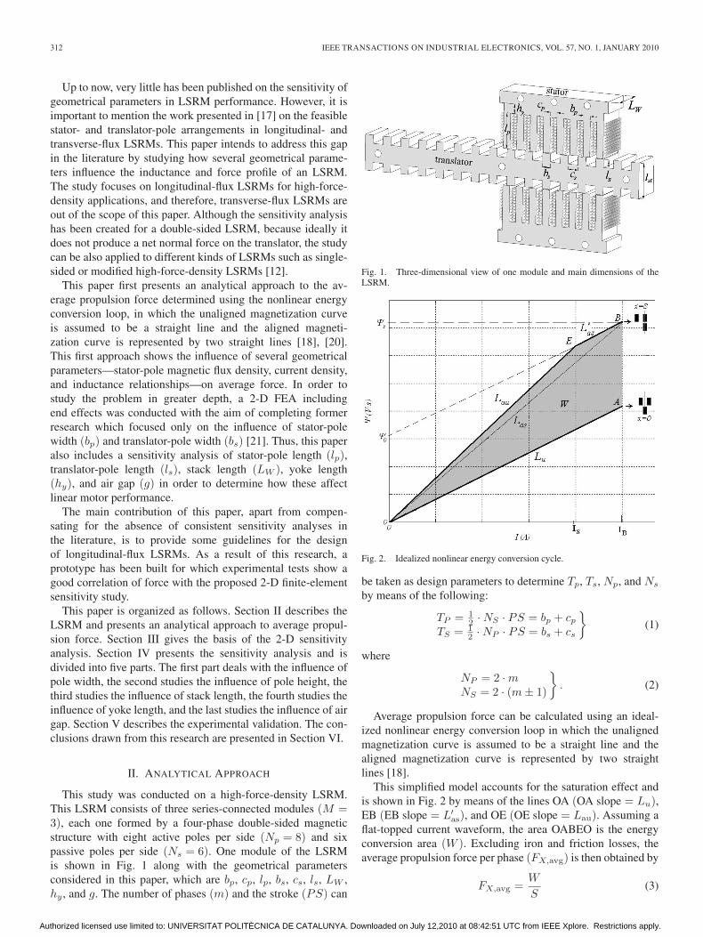
Fig. 4. Triangle for (dark) feasible configurations and (dots) scanning area.
IV. SENSITIVITY ANALYSIS
A. Influence of Pole Widths (bp, bs)
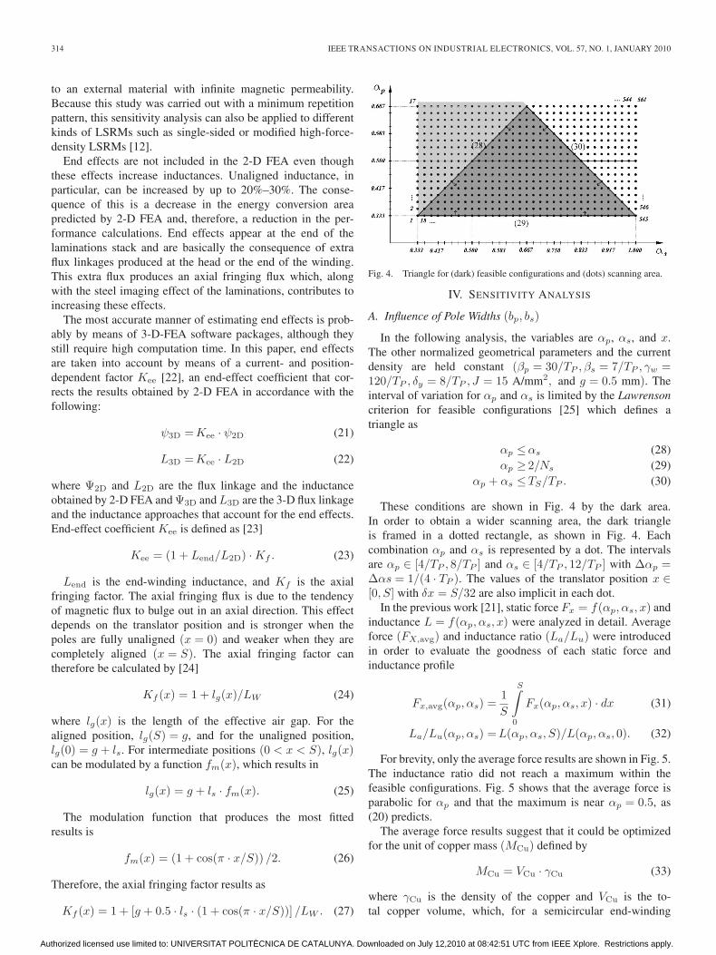
In the following analysis, the variables are αp, αs, and x.The other normalized geometrical parameters and the currentdensity are held constant (βp = 30/TP , βs = 7/TP , γw =120/TP , δy = 8/TP , J = 15 A/mm2, and g = 0.5 mm). Theinterval of variation for αp and αs is limited by the Lawrensoncriterion for feasible configurations [25] which defines atriangle as
αp ≤αs (28)αp ≥ 2/Ns (29)
αp + αs ≤TS/TP . (30)
These conditions are shown in Fig. 4 by the dark area.In order to obtain a wider scanning area, the dark triangleis framed in a dotted rectangle, as shown in Fig. 4. Eachcombination αp and αs is represented by a dot. The intervalsare αp ∈ [4/TP , 8/TP ] and αs ∈ [4/TP , 12/TP ] with Δαp =Δαs = 1/(4 · TP ). The values of the translator position x ∈[0, S] with δx = S/32 are also implicit in each dot.
In the previous work [21], static force Fx = f(αp, αs, x) andinductance L = f(αp, αs, x) were analyzed in detail. Averageforce (FX,avg) and inductance ratio (La/Lu) were introducedin order to evaluate the goodness of each static force andinductance profile
Fx,avg(αp, αs) =1S
S∫0
Fx(αp, αs, x) · dx (31)
La/Lu(αp, αs) = L(αp, αs, S)/L(αp, αs, 0). (32)
For brevity, only the average force results are shown in Fig. 5.The inductance ratio did not reach a maximum within thefeasible configurations. Fig. 5 shows that the average force isparabolic for αp and that the maximum is near αp = 0.5, as(20) predicts.
The average force results suggest that it could be optimizedfor the unit of copper mass (MCu) defined by
MCu = VCu · γCu (33)
where γCu is the density of the copper and VCu is the to-tal copper volume, which, for a semicircular end-winding
Authorized licensed use limited to: UNIVERSITAT POLITÈCNICA DE CATALUNYA. Downloaded on July 12,2010 at 08:42:51 UTC from IEEE Xplore. Restrictions apply.
AMOROS AND ANDRADA: SENSITIVITY ANALYSIS OF GEOMETRICAL PARAMETERS ON DOUBLE-SIDED LSRM 315
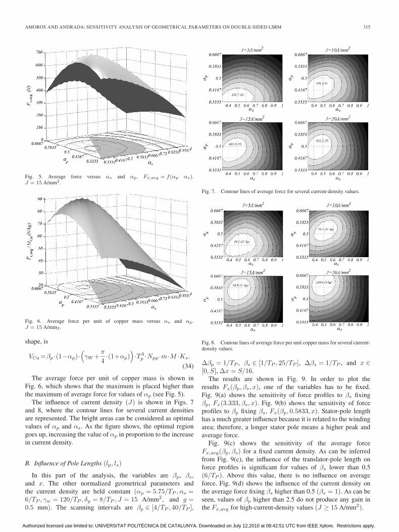
Fig. 5. Average force versus αs and αp. Fx,avg = f(αp αs).J = 15 A/mm2.
Fig. 6. Average force per unit of copper mass versus αs and αp.J = 15 A/mm2.
shape, is
VCu =βp ·(1−αp)·(γW +
π
4·(1+αp)
)·T 3
p ·Npp ·m·M ·Ks.
(34)
The average force per unit of copper mass is shown inFig. 6, which shows that the maximum is placed higher thanthe maximum of average force for values of αp (see Fig. 5).
The influence of current density (J) is shown in Figs. 7and 8, where the contour lines for several current densitiesare represented. The bright areas can be considered as optimalvalues of αp and αs. As the figure shows, the optimal regiongoes up, increasing the value of αp in proportion to the increasein current density.
B. Influence of Pole Lengths (lp, ls)
In this part of the analysis, the variables are βp, βs,and x. The other normalized geometrical parameters andthe current density are held constant (αp = 5.75/TP , αs =6/TP , γw = 120/TP , δy = 8/TP , J = 15 A/mm2, and g =0.5 mm). The scanning intervals are βp ∈ [4/TP , 40/TP ],
Fig. 7. Contour lines of average force for several current-density values.
Fig. 8. Contour lines of average force per unit copper mass for several current-density values.
Δβp = 1/TP , βs ∈ [1/TP , 25/TP ], Δβs = 1/TP , and x ∈[0, S], Δx = S/16.
The results are shown in Fig. 9. In order to plot theresults Fx(βp, βs, x), one of the variables has to be fixed.Fig. 9(a) shows the sensitivity of force profiles to βs fixingβp, Fx(3.333, βs, x). Fig. 9(b) shows the sensitivity of forceprofiles to βp fixing βs, Fx(βp, 0.5833, x). Stator-pole lengthhas a much greater influence because it is related to the windingarea; therefore, a longer stator pole means a higher peak andaverage force.
Fig. 9(c) shows the sensitivity of the average forceFx,avg(βp, βs) for a fixed current density. As can be inferredfrom Fig. 9(c), the influence of the translator-pole length onforce profiles is significant for values of βs lower than 0.5(6/TP ). Above this value, there is no influence on averageforce. Fig. 9(d) shows the influence of the current density onthe average force fixing βs higher than 0.5 (βs = 1). As can beseen, values of βp higher than 2.5 do not produce any gain inthe Fx,avg for high-current-density values (J ≥ 15 A/mm2).
Authorized licensed use limited to: UNIVERSITAT POLITÈCNICA DE CATALUNYA. Downloaded on July 12,2010 at 08:42:51 UTC from IEEE Xplore. Restrictions apply.

316 IEEE TRANSACTIONS ON INDUSTRIAL ELECTRONICS, VOL. 57, NO. 1, JANUARY 2010
Fig. 9. Sensitivity of pole lengths.
C. Influence of Stack Length (LW )
In this part of the analysis, the variables are γw and x.The other geometrical parameters and the current density areheld constant (αp = 5.75/TP , αs = 6/TP , δy = 8/TP , J =15 A/mm2, and g = 0.5 mm). The scanning intervals are γw ∈[10/TP , 120/TP ], Δγw = 5/TP and x ∈ [0, S], Δx = S/32.Fig. 10 shows the results for Fx(γw, x) and Fx,avg(γw, J).Fig. 10(a) shows the sensitivity of γw on force profiles.Fig. 10(b) shows the sensitivity of γw on the average forcefor several current densities, which shows that average forceincreases linearly with stack length.
D. Influence of Yoke Length (hy)
In this part of the analysis, the variables are δy andx. The other geometrical parameters are held constant(αp = 5.75/TP , αs = 6/TP , βp = 30/TP , βs = 7/TP , γw =120/TP , and g = 0.5 mm).
The scanning intervals are δy ∈ [2/TP , 12/TP ], Δδy =1/(2 · TP ) and x ∈ [0, S], Δx = S/32. The results of the
analysis are shown in Fig. 11. Fig. 11(a) shows the sensitivityof δy on force profiles Fx(δy, x) for a current density of J =15 A/mm2. The influence of the yoke length on force for severalcurrent densities Fx,avg(δy, J) is significant for values of δy
lower than 0.5417 (6.5/TP ) [Fig. 11(b)]. Above this value,there is no influence on the average force.
E. Influence of Air-Gap Length (g)
In LSRMs, the air gap does not condition any other dimen-sion; therefore, the air gap does not need to be normalized. Thevariables in this part of the analysis are air-gap length g andthe position of the translator x. The other geometrical parame-ters and the current density are held constant: αp = 5.75/TP ,αs = 6/TP , βp = 30/TP , βs = 7/TP , γw = 120/TP , and J =15 A/mm2. The scanning intervals are g ∈ [0.3 mm, 1.4 mm],Δg = 0.1 mm and x ∈ [0, S], Δx = S/32. Fig. 12(a) showsthe sensitivity of force profiles Fx(g, x). The sensitivity of air-gap length g on the average force Fx,avg(g, x) can be seen inFig. 12(b) and emphasizes the importance of air-gap length
Authorized licensed use limited to: UNIVERSITAT POLITÈCNICA DE CATALUNYA. Downloaded on July 12,2010 at 08:42:51 UTC from IEEE Xplore. Restrictions apply.

AMOROS AND ANDRADA: SENSITIVITY ANALYSIS OF GEOMETRICAL PARAMETERS ON DOUBLE-SIDED LSRM 317
Fig. 10. Sensitivity of stack length.
Fig. 11. Sensitivity of yoke length.
Fig. 12. Sensitivity of air-gap length.
Authorized licensed use limited to: UNIVERSITAT POLITÈCNICA DE CATALUNYA. Downloaded on July 12,2010 at 08:42:51 UTC from IEEE Xplore. Restrictions apply.

318 IEEE TRANSACTIONS ON INDUSTRIAL ELECTRONICS, VOL. 57, NO. 1, JANUARY 2010
TABLE ILSRM PROTOTYPE MAIN DIMENSIONS
TABLE IILSRM PROTOTYPE NORMALIZED MAIN DIMENSIONS
Fig. 13. View of LSRM prototype and load cell detail.
since a smaller air gap results in higher average force values,but there has to be a minimum air gap to allow for clearanceand tolerances.
V. EXPERIMENTAL VALIDATION
An LSRM prototype was built and tested in order to provide abetter illustration of the proposed 2-D finite-element sensitivityanalysis and to evaluate the results.
The main dimensions of the LSRM prototype are shown inTable I. Table II shows the normalized main dimensions of theprototype optimized for the average force per unit copper massand J = 10 A/mm2.
Static propulsion force was measured directly by a load cell.A photograph of the LSRM prototype and a detailed view ofthe load cell are shown in Fig. 13. Fig. 14 shows a comparisonof the force profiles obtained by 2-D FEA accounting for endeffects and considering the minimum study pattern, those ob-tained by 2-D FEA accounting for end effects and consideringthe complete LSRM, and the measured values.
Fig. 14. Static propulsion force for J = 15 A/mm2. Comparison results.
TABLE IIIAVERAGE FORCE RESULTS (J = 15 A/mm2)
TABLE IVINTERVALS FOR KL
The average force results are listed in Table III. The KL co-efficient defined in (9) depends on the geometrical parametersand the current density. Table IV shows the results obtained bythe sensitivity FE analysis.
VI. CONCLUSION
This paper has investigated the influence of several geomet-rical parameters on the force profile of a double-sided LSRM.Experimental results confirm a good correlation between forceand the proposed 2-D finite-element sensitivity study. If themaximum average force has to be an optimizing factor, thefollowing rules concerning the geometrical parameters involvedin the study could be useful.
1) Primary pole width: αp =0.4167 or bp =TP /2.4 (seeFig. 7).
2) Secondary pole width: αs =0.5 or bs =TP /2 (see Fig. 7).3) The relation bs = 1.2bp is a suitable design criterion for
the pole widths.4) Translator-pole length: βs = 0.5 or ls = TP /2 [see
Fig. 9(c)].5) Stator-pole length: lp = 2.5 · TP [see Fig. 9(d)].6) Stack length (LW ) is made to match the average force to
the values expected from the design because the averageforce is proportional to LW [see Fig. 10(b)]. Neverthe-less, an excessive stack increases the mass and iron losses.
Authorized licensed use limited to: UNIVERSITAT POLITÈCNICA DE CATALUNYA. Downloaded on July 12,2010 at 08:42:51 UTC from IEEE Xplore. Restrictions apply.

AMOROS AND ANDRADA: SENSITIVITY ANALYSIS OF GEOMETRICAL PARAMETERS ON DOUBLE-SIDED LSRM 319
7) Yoke length: δy = 0.5417 or hy = TP /1.846 [seeFig. 11(b)] to avoid saturation and loss of average thrust.Higher values do not have any influence and only increasethe stator mass.
8) The air-gap length (g) should be as small as possible tomaximize the average force compatible with tolerancesand manufacturing facilities [see Fig. 12(b)].
9) If the average force per unit of copper mass has to beconsidered, then the best value for the primary pole widthis αp = 0.5 or bp = TP /2 (see Fig. 8).
ACKNOWLEDGMENT
The authors would like to thank Talleres Petit Industries fortheir collaboration.
REFERENCES
[1] T. J. E. Miller, Switched Reluctance Motor and Their Control. Hillsboro,OH: Magna Phys., 1993.
[2] G. Baoming, A. T. de Almeida, and F. Ferreira, “Design of transverseflux linear switched reluctance motor,” IEEE Trans. Magn., vol. 45, no. 1,pp. 113–119, Jan. 2009.
[3] L. Byeong-Seok, B. Han-Kyung, V. Praveen, and R. Krishnan, “Designof a linear switched reluctance machine,” IEEE Trans. Ind. Appl., vol. 36,no. 6, pp. 1571–1580, Nov./Dec. 2000.
[4] N. Chayopitak and D. G. Taylor, “Design of linear variable reluctancemotor using computer-aided design assistant,” in Proc. IEEE Int. Conf.Elect. Mach. Drives, May 2005, pp. 1569–1575.
[5] Z. Sun, N. C. Cheung, J. Pan, S. W. Zhao, and W.-C. Gan, “Design andsimulation of a magnetic levitated switched reluctance linear actuatorsystem for high precision application,” in Proc. IEEE ISIE, Jun. 30–Jul. 2,2008, pp. 624–629.
[6] U. S. Deshpande, J. J. Cathey, and E. Richter, “High-force density linearswitched reluctance machine,” IEEE Trans. Ind. Appl., vol. 31, no. 2,pp. 345–352, Mar./Apr. 1995.
[7] J. Pan, N. C. Cheung, and J. Yang, “High-precision position control ofa novel planar switched reluctance motor,” IEEE Trans. Ind. Electron.,vol. 52, no. 6, pp. 1644–1652, Dec. 2005.
[8] S. W. Zhao, N. C. Cheung, W.-C. Gan, J. M. Yang, and J. F. Pan, “Aself-tuning regulator for the high-precision position control of a linearswitched reluctance motor,” IEEE Trans. Ind. Electron., vol. 54, no. 5,pp. 2425–2434, Oct. 2007.
[9] L. Kolomeitsev, D. Kraynov, F. Pakhomin, F. Rednov, E. Kallenbach,V. Kireev, T. Schneider, and J. Böcker, “Linear switched reluctance mo-tor as high efficiency propulsion system for railway vehicles,” in Proc.SPEEDAM, 2008, pp. 155–160.
[10] H. S. Lim and R. Krishnan, “Ropeless elevator with linear switchedreluctance motor drive actuation systems,” IEEE Trans. Ind. Electron.,vol. 54, no. 4, pp. 2209–2218, Aug. 2007.
[11] H. S. Lim, R. Krishnan, and N. S. Lobo, “Design and control of a linearpropulsion system for an elevator using linear switched reluctance motordrives,” IEEE Trans. Ind. Electron., vol. 55, no. 2, pp. 534–542, Feb. 2008.
[12] N. S. Lobo, H. S. Lim, and R. Krishnan, “Comparison of linear switchedreluctance machines for vertical propulsion application: Analysis, design,and experimental correlation,” IEEE Trans. Ind. Appl., vol. 44, no. 4,pp. 1134–1142, Jul./Aug. 2008.
[13] R. Arumugam, J. F. Lindsay, and R. Krishnan, “Sensitivity of pole arc/polepitch ratio on switched reluctance motor performance,” in Conf. Rec.IEEE IAS Annu. Meeting, Pittsburgh, PA, Oct. 1988, vol. 1, pp. 50–54.
[14] J. Faiz and J. W. Finch, “Aspects of design optimization for switchedreluctance motors,” IEEE Trans. Energy Convers., vol. 8, no. 4, pp. 704–713, Dec. 1993.
[15] S. S. Murthy, B. Singh, and V. K. Sharma, “Finite element analysis toachieve optimum geometry of switched reluctance motor,” in Proc. IEEETENCON, 1998, vol. 2, pp. 414–418.
[16] N. K. Sheth and K. R. Rajagopal, “Optimum pole arcs for a switchedreluctance motor for higher torque with reduced ripple,” IEEE Trans.Magn., vol. 39, no. 5, pp. 3214–3216, Sep. 2003.
[17] C. T. Liu and Y.-N. Chen, “On the feasible polygon classification of linearswitched reluctance machines,” IEEE Trans. Energy Convers., vol. 14,no. 4, pp. 1282–1287, Dec. 1999.
[18] T. J. E. Miller, “Converter volt-ampere requirements of the switched reluc-tance motor drive,” IEEE Trans. Ind. Appl., vol. IA-21, no. 5, pp. 1136–1144, Sep./Oct. 1985.
[19] R. Krishnan, R. Arumugam, and J. F. Lindsay, “Design procedure forswitched-reluctance motors,” IEEE Trans. Ind. Appl., vol. 24, no. 3,pp. 456–461, May/Jun. 1988.
[20] I. Boldea and S. A. Nasar, Linear Electric Actuators and Generators.Cambridge, U.K.: Cambridge Univ. Press, 1997, pp. 173–175.
[21] J. G. Amoros, P. Andrada, L. Massagués, and P. Iñiguez, “Sensitivityanalysis of several geometrical parameters on linear switched reluctancemotor performance,” in Proc. XVIII ICEM, Vilamoura, Portugal, Sep. 6–9,2008, pp. 1–6.
[22] F. D’hulster, K. Stockman, and R. J. M. Belmans, “Modelling of switchedreluctance machines: State of the art,” Int. J. Model. Simul., vol. 24, no. 4,pp. 216–223, 2004.
[23] A. Matveev, V. Kuzmichev, and E. Lomonova, “A new comprehensiveapproach to estimation of end-effects in switched reluctance motors,” inProc. ICEM, Bruges, Belgium, Aug. 2002.
[24] T. J. E. Miller, “Optimal design of switched reluctance motors,” IEEETrans. Ind. Electron., vol. 49, no. 1, pp. 15–27, Feb. 2002.
[25] P. J. Lawrenson, J. M. Stephenson, P. T. Blenkinsop, J. Corda, andN. N. Fulton, “Variable-speed switched reluctance motors,” Proc. Inst.Elect. Eng.—Elect. Power Appl., vol. 127, no. 4, pp. 253–265, Jul. 1980.
J. G. Amoros (M’09) received the M.Sc. de-gree in industrial engineering from the UniversitatPolitecnica de Catalunya (UPC), Barcelona, Spain,in 2004, where he is currently working toward thePh.D. degree in electrical engineering.
Currently, he is also an Associate Professor ofelectrical machines at the Universitat Rovira i Virgili,Tarragona, Spain. His research interests are in thearea of design and modeling of electrical machinesand drives.
P. Andrada (M’91) received the M.Sc. and Ph.D. de-grees in industrial engineering from the UniversitatPolitecnica de Catalunya (UPC), Barcelona, Spain,in 1980 and 1990, respectively.
In 1980, he joined the Department of ElectricalEngineering, UPC, where he is currently an AssistantProfessor in the Engineering School of Vilanova i laGeltrú (EPSEVG). His research interests are in thearea of design and modeling of electrical machinesand drives.
Authorized licensed use limited to: UNIVERSITAT POLITÈCNICA DE CATALUNYA. Downloaded on July 12,2010 at 08:42:51 UTC from IEEE Xplore. Restrictions apply.