Embed Size (px)
Citation preview

Shrink Discs®, Smart-Lock & Shaft Couplings
US08|2009
Partner for performance
copyright 2012 maryland metrics/ringfeder power transmission gmbh
RINGFEDER Products are available from MARYLAND METRICSP.O. Box 261 Owings Mills, MD 21117 USA phones: (410)358-3130 (800)638-1830 faxes: (410)358-3142 (800)872-9329
email: [email protected] web: http://mdmetric.com RFQ form: http://mdmetric.com/rfq.htm
RINGFEDER Products are available from MARYLAND METRICS

A Global Presence For You
The RINGFEDER POWER TRANSMISSION GMBH was founded in 1922 in Krefeld, Germany to fabricate and promote Friction Spring technol-ogy. Today we have expanded our offerings to top power transmission and damping products. Innovative thinking sets us apart and allows us to develop progressive and economical solutions to support our customers.
2

Special applications require special solutions
Our extensive range of RINGFEDER POWER TRANSMISSION products can be applied to solve most applications. We don´t just sell, but by under-standing the individual requirements of our cus-
tomers (e.g. loads on the components, easy instal-lation/removal capability and reduction of produc-tion costs) assist you in every step with innova-tive engineering to plan efficient and technically mature solutions.
3

Content
ContentAll technical details and information is non-binding and cannot be used as a basis for legal claims. The user is obligated to determine whether the represented products meet his requirements. We reserve the right at all times to carry out modifications in the interests of technical progress. Upon the issue of this catalogue all previous brochures and questionnaires on the products displayed are no longer valid.
Content
Content
Content
Overview ............................................................................................... Page 6
Characteristics ................................................................................... Page 8
RINGFEDER® RfN 4012 ................................................................. Page 10
RINGFEDER® RfN 4023 ................................................................. Page 12
RINGFEDER® RfN 4051 ................................................................. Page 16
RINGFEDER® RfN 4061 ................................................................. Page 24
RINGFEDER® RfN 4071 ................................................................. Page 32
RINGFEDER® RfN 4073 ................................................................. Page 36
RINGFEDER® RfN 4091 ................................................................. Page 40
RINGFEDER® RfN 4161 ................................................................. Page 48
RINGFEDER® RfN 4171 ................................................................. Page 52
RINGFEDER® RfN 4181 ................................................................. Page 56
RINGFEDER® RfN 4071 Stainless ............................................................................................... Page 60
Shrink Discs®
4

Content
Content
Content
Content
Content
Smart-Lock
Shaft Couplings
RINGFEDER® RfN 4001 ................................................................. Page 66
Smart-Lock Parts ............................................................................. Page 72
Overview ............................................................................................... Page 74
Characteristics ................................................................................... Page 76
RINGFEDER® WK 5071 ................................................................. Page 78
RINGFEDER® WK 5091 ................................................................. Page 82
Installation and removal instructions
Shrink Discs® ...................................................................................... Page 86
Shrink Discs® Stainless ............................................................................................... Page 90
5

RINGFEDER® Shrink Discs®
RfN 4071Standard Series
RfN 4073Ultra Light Duty Series
RfN 4091Heavy Duty Series
RfN 4181Heavy Duty Series
RfN 4023Light Duty Series
RfN 4051Light Duty Series
RfN 4051Light Duty Series,
split
RfN 4061Standard Series,
split
RfN 4061Standard Series
RfN 4071Standard Series,
split
RfN 4091Heavy Duty Series,
split
RfN 4161Standard Series
RfN 4171Standard Series
RfN 4012Light Duty Series
6

7
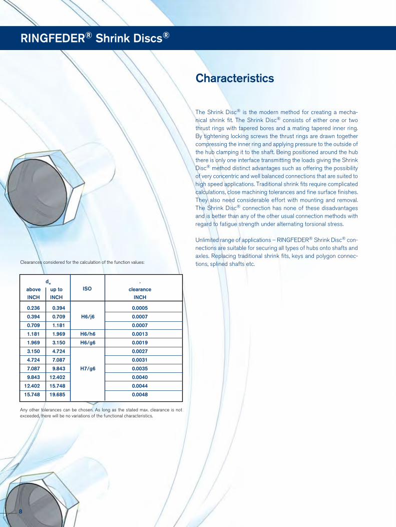
The Shrink Disc® is the modern method for creating a mecha-nical shrink fit. The Shrink Disc® consists of either one or two thrust rings with tapered bores and a mating tapered inner ring. By tightening locking screws the thrust rings are drawn together compressing the inner ring and applying pressure to the outside of the hub clamping it to the shaft. Being positioned around the hub there is only one interface transmitting the loads giving the Shrink Disc® method distinct advantages such as offering the possibility of very concentric and well balanced connections that are suited to high speed applications. Traditional shrink fits require complicated calculations, close machining tolerances and fine surface finishes. They also need considerable effort with mounting and removal. The Shrink Disc® connection has none of these disadvantages and is better than any of the other usual connection methods with regard to fatigue strength under alternating torsional stress.
Unlimited range of applications – RINGFEDER® Shrink Disc® con-nections are suitable for securing all types of hubs onto shafts and axles. Replacing traditional shrink fits, keys and polygon connec-tions, splined shafts etc.
Characteristics
dw ISO
.
above up to clearance
INCH INCH INCH
0.236 0.394 0.0005
0.394 0.709 H6/j6 0.0007
0.709 1.181 0.0007
1.181 1.969 H6/h6 0.0013
1.969 3.150 H6/g6 0.0019
3.150 4.724 0.0027
4.724 7.087 0.0031
7.087 9.843 H7/g6 0.0035
9.843 12.402 0.0040
12.402 15.748 0.0044
15.748 19.685 0.0048
Clearances considered for the calculation of the function values:
Any other tolerances can be chosen. As long as the stated max. clearance is not exceeded, there will be no variations of the functional characteristics.
RINGFEDER® Shrink Discs®
8

Explanations to tables
d, D, L, l, L1, L2, d1 = Basic dimensions
dW = solid shaft diameter (provided by the customer)
T = transmissible torque
Fax = transmissible axial force
p = approx. surface pressure on the hub extension (diameter d)
TA = required tightening torque per screw (Screws greased with molykote or equivalent!)
n = quantity of screws
Tmax = maximum theoretical transmissible torque
Cw = shaft clearances
Ch = hub tolerances
Cd = shaft tolerances
|1 = Inner ring centering shoulder length
d2 = clamped component bore
x = clamped component thickness
B = width dimension, relaxed condition
R1 = hub max. radius (split Shrink Disc®)
sv = calculated combined stress in the hub extension (d/dw) under consideration of the tangential, radial and torsional stresses following the equation:
Additional loads, e.g. tension, thrust or bending have to be taken into consideration accordingly.
Function values The functional characteristics are valid with the screw tight-ening torque listed in the tables and the following assumed conditions:
The locking screws are lubricated using MoS2 (µtot= 0.1).The tapered cones are lubricated using MoS2 (µ = 0.05). The contact surfaces (dw) are in lightly oiled condition with coefficient of friction µ = 0.12.
The hub and shaft materials have a modulus of elasticity of 30 x 106 PSI. (Lower values result in increased values for T and Fax with reduced tangential stress.)
The maximum clearance is being fully utilized. The shaft being used is solid, for hollow shaft applications the functional values will change.
In cases where the assumed conditions do not apply then contact our Technical Department where we will be happy to assist you with your application.
9
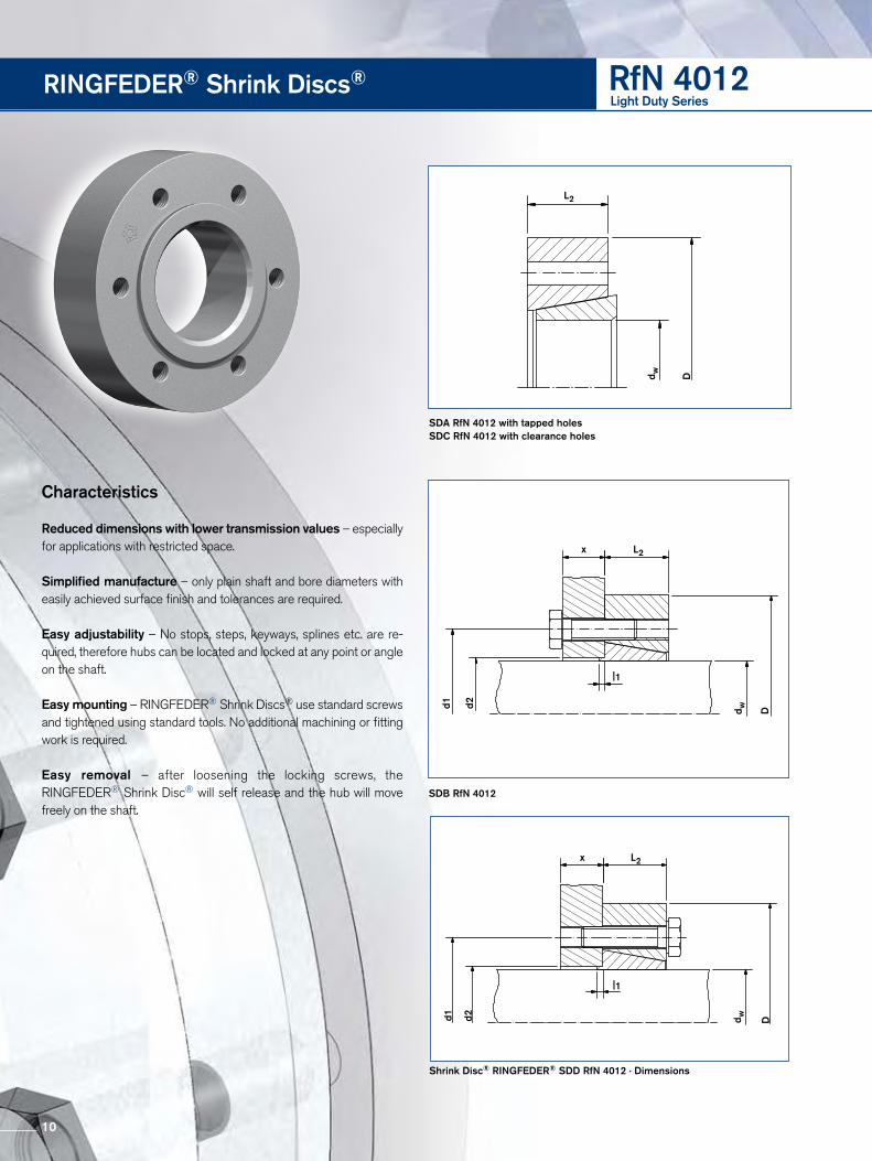
SDA RfN 4012 with tapped holes SDC RfN 4012 with clearance holes
Shrink Disc® RINGFEDER® SDD RfN 4012 · Dimensions
L2
d w D
d1 d2
x L2
|1
d w D
SDB RfN 4012
d1 d2
x L2
|1
d w D
RINGFEDER® Shrink Discs® RfN 4012Light Duty Series
Characteristics
Reduced dimensions with lower transmission values – especially for applications with restricted space.
Simplified manufacture – only plain shaft and bore diameters with easily achieved surface finish and tolerances are required.
Easy adjustability – No stops, steps, keyways, splines etc. are re-quired, therefore hubs can be located and locked at any point or angle on the shaft.
Easy mounting – RINGFEDER® Shrink Discs® use standard screws and tightened using standard tools. No additional machining or fitting work is required.
Easy removal – after loosening the locking screws, the RINGFEDER® Shrink Disc® will self release and the hub will move freely on the shaft.
10

RfN 4012 Light Duty Series
Transmissible Torques Locking screws* WeightDIN EN ISO 4014-10.9
Quantity Thread WTType dw Cd D d1 d2 h7 Ch L2 l1 TA T
Inch Inch Inch Inch Inch Inch Inch Inch lb-ft lb-ft n lbs
0.354+0
-0.0004
+0 -0.0007
15 10 SD-x 1.535 0.984 0.472 0.394 0.059 9 3 M6 0.2
0.433 15 0.433
+0 -0.0006
37 12 SD-x 1.732 1.102 0.551 0.512 0.059 9 3 M6 0.2
0.512 37 0.551 96
15 SD-x 2.047 1.417 0.709 0.591 0.079 22 3 M8 0.4 0.630 96 0.630
+0 -0.0007
148 20 SD-x 2.362 1.654 0.866 0.669 0.079 22 3 M8 0.7
0.787 148 0.787
+0 -0.0008
251 25 SD-x 2.598 1.890 1.063 0.748 0.079 22 5 M8 0.9
0.984 251 0.984 406
30 SD-x 2.992 2.205 1.260 0.827 0.079 22 6 M8 1.3 1.181 406 1.181
+0 -0.0013
+0 -0.0010
782 40 SD-x 3.780 2.756 1.693 0.984 0.118 44 6 M10 2.6
1.575 782 1.575 1106
50 SD-x 4.409 3.307 2.087 1.181 0.118 74 7 M12 4.0 1.969 1623
Design SDA and SDC without centering · Ordering example: 40 SDA 35 RfN 4012 · * Shrink discs® delivered without screws
11

Shrink Disc® RINGFEDER® SDB RfN 4023 · Location
x L2
d1 d2
|1
d w D
Shrink Disc® RINGFEDER® SDD RfN 4023 · Dimensions
x L2
d1 d2
|1
d w D
RINGFEDER® Shrink Discs® RfN 4023Heavy Duty Series
12

To continue see next page
RfN 4023 Heavy Duty Series
Shrink Disc® Dimensions Transmissible Torques Locking screws* WeightDIN EN ISO 4014-10.9
Quantity Thread WTType dw Cd D d1 d2 Ch L2 |1 TA T
Inch Inch Inch Inch Inch Inch Inch Inch lb-ft lb-ft n lbs
1.575
+0 -0.0011
+0
-0.0010
1033 50 SD-x 4.528 3.307 2.087 1.181 0.118 74 7 M12 4.4
1.969 2434 1.969
+0 -0.0012
1696 60 SD-x 4.724 3.700 2.480 1.339 0.118 74 9 M12 4.8
2.362 3466 2.362 4278
70 SD-x 5.827 4.409 2.913 1.575 0.157 184 8 M16 10 2.756 6933 2.756 5900
80 SD-x 6.693 5.118 3.307 1.732 0.157 184 9 M16 13 3.150 8850 3.150
+0 -0.0013
+0 -0.0014
8850 90 SD-x 7.283 5.669 3.701 1.969 0.157 184 12 M16 18
3.543 13275 3.543 11800
100 SD-x 7.756 6.142 4.094 2.126 0.157 184 14 M16 21 3.937 16963 3.937 16225
110 SD-x 8.465 6.535 4.567 2.283 0.197 362 10 M20 27 4.331 19913 4.331 24338
120 SD-x 9.055 7.323 4.961 2.559 0.197 362 14 M20 75 4.724 31713 4.724
+0 -0.0015
+0 -0.0016
28763 140 SD-x 11.417 8.504 5.748 2.992 0.197 362 16 M20 145
5.512 41300 5.512 47200
160 SD-x 12.598 9.213 6.535 3.268 0.197 627 14 M24 189 6.299 56788 6.299 62688
180 SD-x 13.386 10.870 7.323 3.701 0.197 627 16 M24 105 7.087 76700 7.087
+0 -0.0017
+0
-0.0018
84075 200 SD-x 14.567 11.420 8.110 3.780 0.197 922 16 M27 125
7.874 106200
Design SDA and SDC without centering · Ordering example: 40 SDA 35 RfN 4023 · * Shrink discs® delivered without screws
13

RINGFEDER® Shrink Discs® RfN 4023Heavy Duty Series
Characteristics
Reduced dimensions with lower transmission values – especially for applications with restricted space.
Simplified manufacture – only plain shaft and bore diameters with easily achieved surface finish and tolerances are required.
Easy adjustability – No stops, steps, keyways, splines etc. are re-quired, therefore hubs can be located and locked at any point or angle on the shaft.
Easy mounting – RINGFEDER® Shrink Discs® use standard screws and tightened using standard tools. No additional machining or fitting work is required.
Easy removal – after loosening the locking screws, the RINGFEDER® Shrink Disc® will self release and the hub will move freely on the shaft.
Low susceptibility to contamination – when the locking screws are tightened the contact (functional) surfaces are pressed firmly together and prevent contamination by dirt and moisture.
Highest reliability – due to the materials chosen and manufacturing processes used, RINGFEDER® Shrink Discs® can be tightened and released as often as required. If locking screws need replacing, they are standard items and thus easily available.
14

More sizes on request
RfN 4023 Heavy Duty Series
Shrink Disc® Dimensions Transmissible Torques Locking screws* WeightDIN EN ISO 4014-10.9
Quantity Thread WTType dw Cd D d1 d2 Ch L2 |1 TA T
Inch Inch Inch Inch Inch Inch Inch Inch lb-ft lb-ft n lbs
7.874
+0 -0.0035
+0 -0.0018
117263 220 SD-x 15.945 12.598 8.898 3.937 0.197 922 18 M27 156
8.661 131275 8.661 155613
240 SD-x 16.929 13.386 9.685 4.331 0.197 922 20 M27 189 9.449 155613 9.449
+0 -0.0040
+0 -0.0020
172575 260 SD-x 18.110 14.016 11.260 4.882 0.197 922 21 M27 241
10.236 171100 10.236 172575
280 SD-x 19.094 14.173 12.05 5.118 0.197 922 21 M27 275 11.024 172575 11.024 182163
300 SD-x 20.472 14.961 12.99 5.118 0.197 922 21 M27 317 11.811 182163 11.811
+0 -0.0022
220513 320 SD-x 21.654 15.827 13.780 5.354 0.315 922 24 M27 367
12.598 220513 12.598
+0 -0.0044
232313 340 SD-x 22.441 16.693 14.57 5.630 0.315 922 24 M27 403
13.386 232313 13.386 302375
360 SD-x 24.016 17.874 15.75 5.787 0.315 1254 24 M30 480 14.173 302375 14.173 323763
390 SD-x 24.803 19.134 16.93 6.575 0.315 1254 24 M30 550 15.354 323763 15.354
+0 -0.0048
+0 -0.0025
337038 420 SD-x 26.378 19.921 17.72 6.890 0.394 1254 24 M30 642
16.535 337038 15.748 414475
440 SD-x 27.559 21.024 18.5 6.890 0.394 1254 28 M30 700 17.323 414475
Design SDA and SDC without centering · Ordering example: 40 SDA 35 RfN 4023 · * Shrink discs® delivered without screws
15

Shrink Disc® RINGFEDER® RfN 4051 · Location
Thrust bearing locking collar (metric example)
Shrink Disc® RINGFEDER® RfN 4051 · Dimensions
RINGFEDER® Shrink Discs® RfN 4051Light Duty Series
16

To continue see next page
RfN 4051 Light Duty Series
Size Shrink Disc® dimensions Transmissibletorques oraxial forces
Locking screwsDIN EN ISO 4014-10.9
Weight
dw Cw d Ch D L1 L d1 L2 I TA P σv Quantity WT TmaxT Fax Thread
Inch Inch Inch Inch Inch Inch Inch Inch Inch Inch lb-ft lb-ft lbs psi psi n lbs lb-ft
3.740
0.0027
+0 -0.0025
7781 49456 40310 9736125 4.921 7.283 2.283 2.008 6.220 0.866 1.535 44 27695 8
M10x40 13
4.134 10178 58448 41760 12723 4.331 10916 59572 38860 13645
140 5.512 8.661 2.283 2.008 6.890 0.866 1.535 44 27840 9 M10x40 18 4.921 15120 73060 45675 18900 5.118
0.0031
17701 82052 42485 22127155 6.102 9.646 2.283 2.008 7.559 0.866 1.535 44 30740 11 M10x40 22 5.512 21389 92168 48430 26737 5.315 23602 106780 43210 29502
165 6.496 10.236 2.756 2.441 8.268 1.024 1.811 74 32480 10 M12x50 31 5.709 28396 119144 47415 35495 5.709 28765 120268 43790 35956
175 6.890 10.827 2.756 2.441 8.661 1.024 1.811 74 33640 11 M12x50 35 6.102 33928 132632 48430 42410 6.102
+0 -0.0028
34370 134880 44515 42963185 7.283 11.614 2.756 2.441 8.858 1.024 1.811 74 34800 12 M12x50 44 6.496 39828 146120 49445 49785 6.496 46466 170848 44370 58083
195 7.677 12.402 3.150 2.835 9.331 1.220 2.205 74 33785 15 M12x55 60 6.890 53473 185460 51475 66841 6.890 54579 191080 48430 68316
200 7.874 12.992 3.150 2.835 9.528 1.220 2.205 74 35235 16 M12x55 66 7.283 62324 205692 63800 77905 7.087
0.0035
61070 206816 40165 76337220 8.661 13.583 3.701 3.307 10.433 1.417 2.598 184 31900 10 M16x65 77 7.874 77444 237164 53215 96805 7.874 83344 255148 44080 104180
240 9.449 14.567 3.701 3.307 11.417 1.417 2.598 184 35235 12 M16x65 97 8.465 99202 281000 51620 124002 8.661
+0 -0.0032
109896 303480 43935 137371260 10.236 15.551 4.016 3.622 12.205 1.575 2.835 184 34800 14 M16x70 106 9.252 127598 331580 52780 159497 9.055 126123 333828 39150 157653
280 11.024 16.732 4.488 4.094 13.110 1.811 3.307 184 31610 16 M16x75 132 9.843 153412 373168 46980 191766 9.843
0.0040
158575 386656 40455 198219300 11.811 18.110 4.488 4.094 14.094 1.811 3.307 184 33205 18 M16x75 165 10.630 188078 424872 49590 235097 10.630
+0 -0.0035
191766 436112 42485 239707320 12.598 19.488 4.567 4.173 14.882 1.890 3.307 184 34655 20 M16x75 185 11.417 225693 477700 51475 282117 11.417 221268 465336 41760 276585
340 13.386 21.063 4.567 4.173 15.827 1.890 3.307 184 34220 21 M16x75 221 12.008 248558 496808 47270 310697 11.811 274372 558628 42340 342965
350 13.780 21.457 5.315 4.803 16.260 2.126 3.937 361 33350 16 M20x90 265 12.205 295024 582232 46400 368780 11.811 265522 539520 39150 331902
360 14.173 21.850 5.315 4.803 16.654 2.126 3.937 361 32335 16 M20x90 276 12.598 306087 582232 45530 382609 12.598
0.0044
320839 611456 38860 401048380 14.961 23.031 5.866 5.354 17.402 2.362 4.409 361 30885 18 M20x100 331 12.992 344441 637308 41325 430551 12.992 372468 687888 41325 465585
390 15.354 23.425 5.866 5.354 17.795 2.362 4.409 361 33350 20 M20x100 344 13.780 425572 740716 48865 531965
17
Characteristics
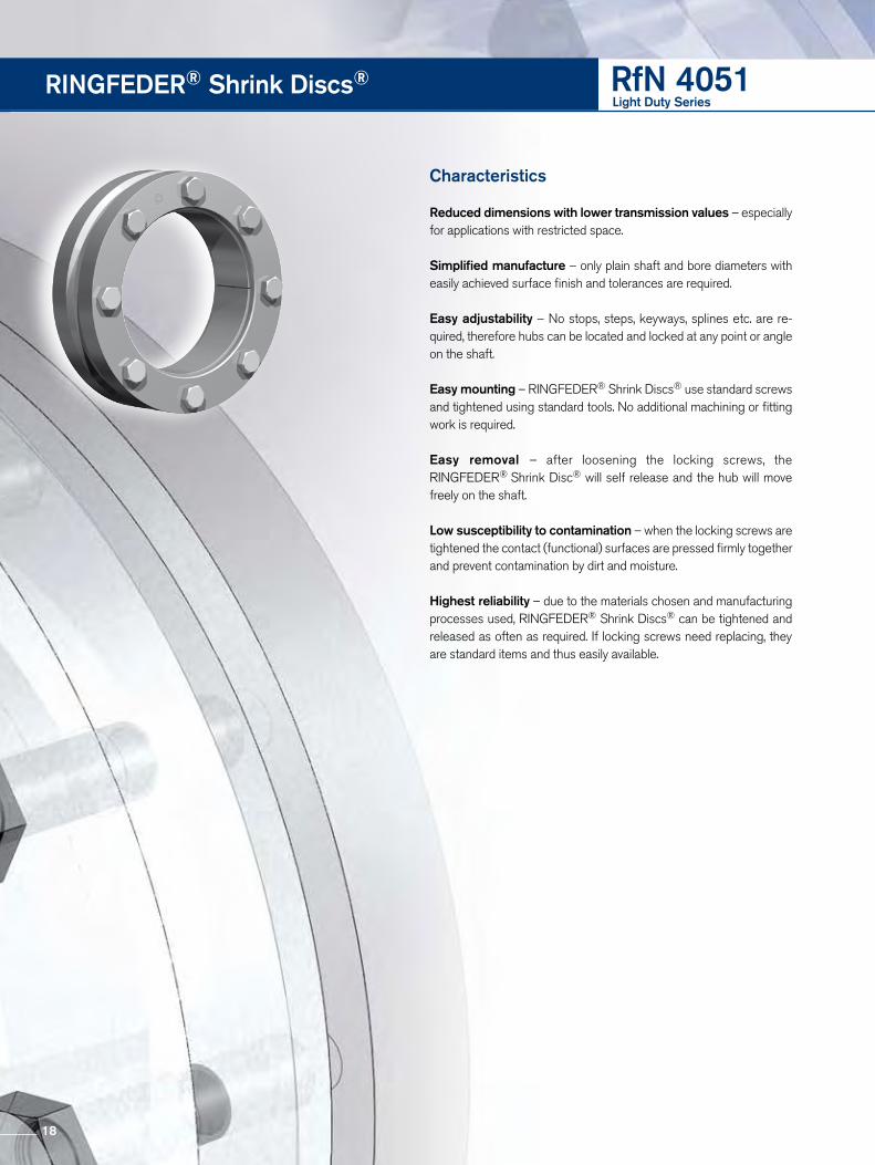
Reduced dimensions with lower transmission values – especially for applications with restricted space.
Simplified manufacture – only plain shaft and bore diameters with easily achieved surface finish and tolerances are required.
Easy adjustability – No stops, steps, keyways, splines etc. are re-quired, therefore hubs can be located and locked at any point or angle on the shaft.
Easy mounting – RINGFEDER® Shrink Discs® use standard screws and tightened using standard tools. No additional machining or fitting work is required.
Easy removal – after loosening the locking screws, the RINGFEDER® Shrink Disc® will self release and the hub will move freely on the shaft.
Low susceptibility to contamination – when the locking screws are tightened the contact (functional) surfaces are pressed firmly together and prevent contamination by dirt and moisture.
Highest reliability – due to the materials chosen and manufacturing processes used, RINGFEDER® Shrink Discs® can be tightened and released as often as required. If locking screws need replacing, they are standard items and thus easily available.
RINGFEDER® Shrink Discs® RfN 4051Light Duty Series
18

More sizes on request
RfN 4051 Light Duty Series
Size Shrink Disc® dimensions Transmissibletorques oraxial forces
Locking screwsDIN EN ISO 4014-10.9
Weight
dw Cw d Ch D L1 L d1 L2 I TA P σv Quantity WT TmaxT Fax Thread
Inch Inch Inch Inch Inch Inch Inch Inch Inch Inch lb-ft lb-ft lbs psi psi n lbs lb-ft
13.386
0.0044
+0 -0.0035
405658 727228 42195 507073400 15.748 24.213 5.866 5.354 18.189 2.362 4.409 361 34220 21 M20x100 375 14.173 461713 782304 50025 577141 13.780
+0 -0.0038
426310 741840 38425 532887420 16.535 24.803 6.181 5.669 19.094 2.520 4.724 361 31755 22 M20x100 408 14.567 483102 796916 43065 603877 14.567 499328 822768 39730 624160
440 17.323 25.984 6.181 5.669 19.882 2.520 4.724 361 33205 24 M20x100 452 15.354 562021 878968 44805 702526 15.354 619550 971136 41035 774438
460 18.110 26.969 6.732 6.220 20.748 2.795 5.197 361 33640 28 M20x110 518 16.142 689619 1029584 47560 862945 16.142
0.0048
657166 977880 39875 821457480 18.898 28.150 6.732 6.220 21.535 2.795 5.197 361 32190 28 M20x110 562 16.732 712483 1022390,4 43645 890604 16.732 727234 1044196 39875 909043
500 19.685 29.528 6.732 6.220 22.323 2.795 5.197 361 33060 30 M20x110 628 17.323 786239 1089156 43065 982799
19

Shrink Disc® RINGFEDER® RfN 4051 split · Location
Shrink Disc® RINGFEDER® RfN 4051 HT · Dimensions
Shrink Disc® RINGFEDER® RfN 4051 HC · Dimensions
RINGFEDER® Shrink Discs® RfN 4051split
D d1 d dw
R1max
L2
B x
D d1 d dw
R1max
L2
B x
D d1 d dw
R1max
L2
B x
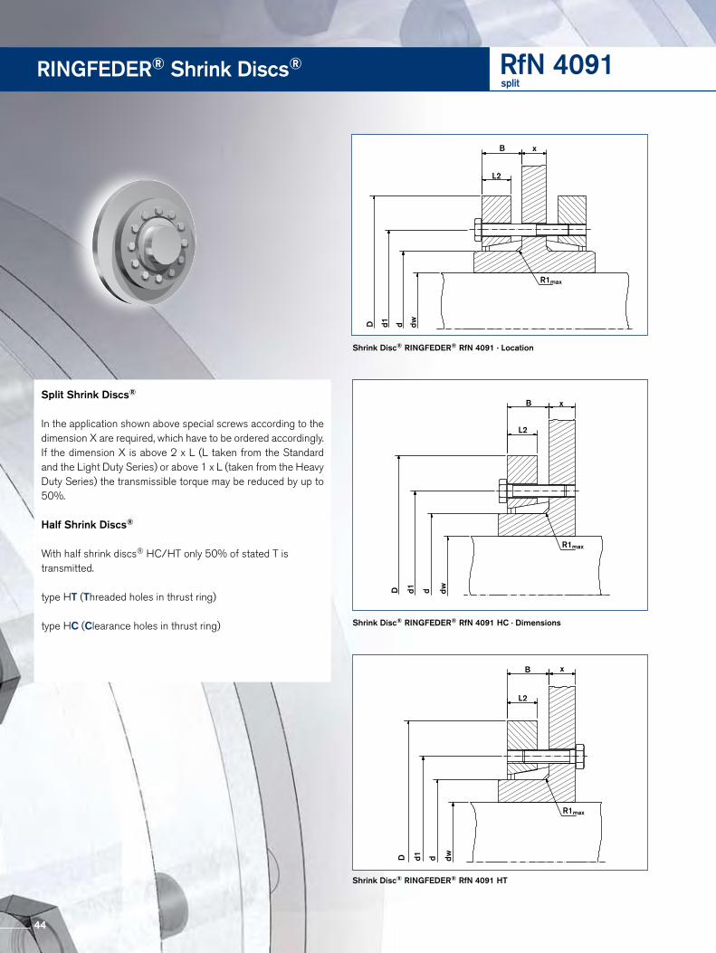
Split Shrink Discs®
In the application shown above special screws according to the dimension X are required, which have to be ordered accordingly. If the dimension X is above 2 x L (L taken from the Standard and the Light Duty Series) or above 1 x L (taken from the Heavy Duty Series) the transmissible torque may be reduced by up to 50%.
Half Shrink Discs®
With half shrink discs® HC/HT only 50% of stated T is transmitted.
type HT (Threaded holes in thrust ring)
type HC (Clearance holes in thrust ring)
20

RfN 4051 split
To continue see next page
Size Shrink Disc® dimensions Transmissibletorques oraxial forces
Locking screwsDIN EN ISO 4014-10.9
Weight
dw Cw d Ch D d1 B±0.039 R1 max TA Quantity Thread WTT Fax
Inch Inch Inch Inch Inch Inch Inch Inch lb-ft lb-ft lbs n lbs
3.740
0.0027
+0 -0.0025
7781 49456 125 4.921 7.283 6.220 1.201 0.189 44 8 M10 13 4.134 10178 58448 4.331 10916 59572
140 5.512 8.661 6.890 1.215 0.189 44 9 M10 18 4.921 15120 73060 5.118
0.0031
17701 82052 155 6.102 9.646 7.559 1.201 0.189 44 11 M10 22 5.512 21389 92168 5.315 23602 106780
165 6.496 10.236 8.268 1.417 0.189 74 10 M12 31 5.709 28396 119144 5.709 28765 120268
175 6.890 10.827 8.661 1.417 0.189 74 11 M12 35 6.102 33928 132632 6.102
+0 -0.0028
34370 134880 185 7.283 11.614 8.858 1.417 0.189 74 12 M12 44 6.496 39828 146120 6.496 46466 170848
195 7.677 12.402 9.331 1.614 0.189 74 15 M12 60 6.890 53473 185460 6.890 54579 191080
200 7.874 12.992 9.528 1.614 0.189 74 16 M12 66 7.283 62324 205692 7.087
0.0035
61070 206816 220 8.661 13.583 10.433 1.850 0.189 184 10 M16 77 7.874 77444 237164 7.874 83344 255148
240 9.449 14.567 11.417 1.850 0.189 184 12 M16 97 8.465 99202 281000 8.661
+0 -0.0032
109896 303480 260 10.236 15.551 12.205 2.067 0.252 184 14 M16 106 9.252 127598 331580 9.055 126123 333828
280 11.024 16.732 13.110 2.343 0.252 184 16 M16 132 9.843 153412 373168 9.843
0.0040
158575 386656 300 11.811 18.110 14.094 2.343 0.252 184 18 M16 165 10.630 188078 424872 10.630
+0 -0.0035
191766 436112 320 12.598 19.488 14.882 2.382 0.252 184 20 M16 185 11.417 225693 477700 11.417 221268 465336
340 13.386 21.063 15.827 2.382 0.252 184 21 M16 221 12.008 248558 496808 11.811 274372 558628
350 13.780 21.457 16.260 2.697 0.252 361 16 M20 265 12.205 295024 582232 11.811 265522 539520
360 14.173 21.850 16.654 2.697 0.252 361 16 M20 276 12.598 306087 582232 12.598
0.0044
320839 611456 380 14.961 23.031 17.402 2.972 0.252 361 18 M20 331 12.992 344441 637308 12.992 372468 687888
390 15.354 23.425 17.795 3.071 0.331 361 20 M20 344 13.780 425572 740716 13.386 405658 727228
400 15.748 24.213 18.189 3.071 0.331 361 21 M20 375 14.173 461713 782304 13.780
+0 -0.0038
426310 741840 420 16.535 24.803 19.094 3.228 0.331 361 22 M20 408
14.567 483102 796916
21

RINGFEDER® Shrink Discs® RfN 4051split
Characteristics
Reduced dimensions with lower transmission values – espe-cially for applications with restricted space.
Simplified manufacture – only plain shaft and bore diameters with easily achieved surface finish and tolerances are required.
Easy adjustability – No stops, steps, keyways, splines etc. are re-quired, therefore hubs can be located and locked at any point or angle on the shaft.
Easy mounting – RINGFEDER® Shrink Discs® use standard screws and tightened using standard tools. No additional machining or fitting work is required.
Easy removal – after loosening the locking screws, the RINGFEDER® Shrink Disc® will self release and the hub will move freely on the shaft.
Low susceptibility to contamination – when the locking screws are tightened the contact (functional) surfaces are pressed firmly together and prevent contamination by dirt and moisture.
Highest reliability – due to the materials chosen and manufacturing processes used, RINGFEDER® Shrink Discs® can be tightened and released as often as required. If locking screws need replacing, they are standard items and thus easily available.
22

RfN 4051 split
Size Shrink Disc® dimensions Transmissibletorques oraxial forces
Locking screwsDIN EN ISO 4014-10.9
Weight
dw Cw d Ch D d1 B±0.039 R1 max TA Quantity Thread WTT Fax
Inch Inch Inch Inch Inch Inch Inch Inch lb-ft lb-ft lbs n lbs
14.567
0.0044
+0 -0.0038
499328 822768 440 17.323 25.984 19.882 3.228 0.331 361 24 M20 452 15.354 562021 878968 15.354 619550 971136
460 18.110 26.969 20.748 3.602 0.390 361 28 M20 518 16.142 689619 1029584 16.142
0.0048
657166 977880 480 18.898 28.150 21.535 3.602 0.390 361 28 M20 562 16.732 712483 1022390 16.732 727234 1044196
500 19.685 29.528 22.323 3.602 0.390 361 30 M20 628 17.323 786239 1089156
23

Shrink Disc® RINGFEDER® RfN 4061 · Location
Axial bearing disc
Shrink Disc® RINGFEDER® RfN 4061 · Dimensions
RINGFEDER® Shrink Discs® RfN 4061Standard Series
24

RfN 4061 Standard Series
To continue see next page
Size Shrink Disc® dimensions Transmissibletorques oraxial forces
Locking screwsDIN EN ISO 4014-10.9
Weight
dw Cw d Ch D L1 L d1 L2 I TA P σv Quantity Thread TmaxT Fax
Inch Inch Inch Inch Inch Inch Inch Inch Inch lb-ft lb-ft lbs psi psi n lbs lb-ft
0.394
0.0007
+0 -0.0013
13 1191 99470 1714 0.551 1.457 0.591 0.472 0.945 0.197 0.354 1.5 56105 3 M5x12 0.2 0.472 26 1798 119805 32 0.472 33 2383 100940 4116 1.614 0.728 0.591 1.063 0.246 0.472 3 61250 3 M5x16 0.2 0.551 59 3192 154840 74 0.551 63 3619 113680 7818 0.709 1.732 0.728 0.591 1.142 0.246 0.472 3 72765 4 M5x16 0.2 0.630 96 4518 185465 120 0.591 81 4271 114415 10220 0.787 1.811 0.807 0.669 1.260 0.276 0.472 3 81585 5 M5x16 0.3 0.669 112 5170 152635 140 0.748 162 7194 120540 19924 0.945 1.969 0.906 0.748 1.417 0.315 0.591 3.7 81830 6 M5x18 0.4 0.827 236 8318 165130 295 0.945 280 8542 101185 34730 1.181 2.047 0.984 0.846 1.654 0.354 0.669 3.7 65905 7 M5x20 0.7 1.024 347 9666 124950 435 1.024
+0 -0.0015
278 10790 94325 35436 1.417 2.835 1.083 0.925 2.047 0.394 0.709 9 75215 5 M6x20 0.9 1.181 420 13038 109270 524 1.142
0.0013
479 13488 92365 60538 1.496 2.835 1.181 1.024 2.165 0.433 0.827 9 72030 6 M6x25 1.1 1.220 553 14387 115885 686 1.181 465 13263 98000 58340 1.575 2.953 1.122 0.965 2.244 0.413 0.748 9 76930 6 M6x25 1.2 1.260 538 14162 113925 671 1.260 546 14162 104860 67944 1.732 3.150 1.181 1.024 2.402 0.433 0.787 9 76195 7 M6x25 1.3 1.417 752 17085 111965 937 1.417 538 13713 86730 67148 1.890 3.150 1.181 1.024 2.677 0.433 0.866 9 61005 7 M6x25 1.2 1.575 819 16410 89425 1018 1.496 774 20007 103635 96650 1.969 3.543 1.260 1.102 2.756 0.472 0.866 9 78400 9 M6x25 1.8 1.654 1136 23154 115395 1416 1.654
+0 -0.0018
856 17759 84280 106955 2.165 3.937 1.358 1.201 2.953 0.512 0.906 9 61740 8 M6x25 2.4 1.890 1387 21806 101920 1733 1.890 1637 28100 99470 204362 2.441 4.331 1.378 1.220 3.386 0.512 0.906 9 80850 12 M6x30 2.9 2.047 2132 30348 117845 2663
25

RINGFEDER® Shrink Discs® RfN 4061Standard Series
Characteristics
Reduced dimensions with lower transmission values – especially for applications with restricted space.
Simplified manufacture – only plain shaft and bore diameters with easily achieved surface finish and tolerances are required.
Easy adjustability – No stops, steps, keyways, splines etc. are re-quired, therefore hubs can be located and locked at any point or angle on the shaft.
Easy mounting – RINGFEDER® Shrink Discs® use standard screws and tightened using standard tools. No additional machining or fitting work is required.
Easy removal – after loosening the locking screws, the RINGFEDER® Shrink Disc® will self release and the hub will move freely on the shaft.
Low susceptibility to contamination – when the locking screws are tightened the contact (functional) surfaces are pressed firmly together and prevent contamination by dirt and moisture.
Highest reliability – due to the materials chosen and manufacturing processes used, RINGFEDER® Shrink Discs® can be tightened and released as often as required. If locking screws need replacing, they are standard items and thus easily available.
26

RfN 4061 Standard Series
Size Shrink Disc® dimensions Transmissibletorques oraxial forces
Locking screwsDIN EN ISO 4014-10.9
Weight
dw Cw d Ch D L1 L d1 L2 I TA P σv Quantity Thread WT TmaxT Fax
Inch Inch Inch Inch Inch Inch Inch Inch Inch lb-ft lb-ft lbs psi psi n lbs lb-ft
1.969
0.0019
+0 -0.0018
1475 21356 77910 184468 2.677 4.528 1.378 1.220 3.386 0.512 0.906 9 61250 10 M6x30 3.1 2.362 2323 26976 101675 2899 2.165 1844 26751 90160 230575 2.953 5.433 1.496 1.280 3.937 0.551 0.984 22 66885 7 M8x30 3.7 2.559 2913 34844 100940 3642 2.362 2360 27875 84525 295080 3.150 5.709 1.496 1.280 3.937 0.551 0.984 22 62720 7 M8x30 4.2 2.756 3393 35518 95060 4241 2.362
+0 -0.0021
3172 37991 91630 396185 3.346 6.102 1.890 1.614 4.488 0.669 1.181 22 71050 10 M8x35 7.7 2.756 4861 47658 96040 6070 2.559 3503 38216 84525 438090 3.543 6.102 1.752 1.535 4.488 0.669 1.181 22 66395 10 M8x35 7.3 2.953 5347 47208 90160 6685 2.559 3968 43836 85505 495695 3.740 6.693 2.087 1.850 4.882 0.748 1.339 22 68600 12 M8x40 10 2.953 6048 53952 86975 7560 2.756 5089 43836 79135 6361
100 3.937 6.693 1.949 1.732 4.882 0.748 1.339 22 63210 12 M8x35 10 3.150 6638 53952 81830 8298 2.953 5310 51479 73990 6638
110 4.331 7.283 2.244 1.969 5.354 0.866 1.535 44 59780 9 M10x40 13 3.346 7966 58898 84035 9957 3.150
0.0027
+0 -0.0025
6786 60696 73990 8482115 4.528 7.283 2.402 2.165 5.591 0.906 1.654 44 61005 10 M10x45 13 3.740 11063 74184 86485 13829 3.346 8113 66541 84525 10141
125 3.740 11063 79130 84770 13829 3.740 11137 82502 81095 13921
140 5.512 9.055 2.697 2.382 6.890 1.024 1.811 74 64680 10 M12x45 22 4.134 14825 95540 81095 18531 4.134 16226 100486 78400 20283
155 6.102 10.433 2.854 2.539 7.559 1.102 1.969 74 64435 12 M12x65 33 4.528 20652 114423 78890 25815 4.528 22864 133756 80360 28580
165 6.496 11.417 3.189 2.795 8.268 1.220 2.205 184 67865 8 M16x55 49 4.921 28765 147244 84035 35956 4.921
0.0031
26552 136004 81830 33190175 6.890 11.811 3.189 2.795 8.661 1.220 2.205 184 63945 8 M16x90 49 5.315 33190 151740 79380 41488 5.315
+0 -0.0028
38353 174894 74235 47941185 7.283 12.992 3.780 3.386 9.291 1.496 2.795 184 59780 10 M16x65 82 5.709 45729 193553 76440 57161 5.512 47941 209738 80115 59927
195 7.677 13.780 3.780 3.386 9.685 1.496 2.795 184 67865 12 M16x65 90 6.102 60111 240761 83790 75139 5.906 54579 222552 78890 68224
200 7.874 13.780 3.780 3.386 9.685 1.496 2.795 184 66150 12 M16x65 90 6.299 63430 242784 81830 79288
27

Shrink Disc® RINGFEDER® RfN 4061 split · Location
D d1 d dw
R1max
L2
B x
Shrink Disc® RINGFEDER® RfN 4061 HC · Dimensions
D d1 d dw
R1max
L2
B x
D d1 d dw
R1max
L2
B x
Shrink Disc® RINGFEDER® RfN 4061 HT version
RINGFEDER® Shrink Discs® RfN 4061split
Split Shrink Discs®
In the application shown above special screws according to the dimension X are required, which have to be ordered accordingly. If the dimension X is above 2 x L (L taken from the Standard and the Light Duty Series) or above 1 x L (taken from the Heavy Duty Series) the transmissible torque may be reduced by up to 50%.
Half Shrink Discs®
With half shrink discs® HC/HT only 50% of stated T is transmitted.
type HT (Threaded holes in thrust ring)
type HC (Clearance holes in thrust ring)
28

RfN 4061 split
Size Transmissibletorques oraxial forces
Locking screwsDIN EN ISO 4014-10.9
Weight
Cw d Ch D L2 d1 B±0.039 R1 max TA Quantity Thread WT Tmaxdw T Fax
Inch Inch Inch Inch Inch Inch Inch Inch Inch lb-ft lb-ft lbs n lbs lb-ft
0.591
+0 -0.0013
4271 81 8920 0.787 1.811 0.197 1.260 0.453 0.051 3 5 M5 0,3 0.669 5170 112 123 0.748
0.0007
7194 162 17824 0.945 1.969 0.246 1.417 0.463 0.051 4 6 M5 0,4 0.827 8318 236 260 0.945 8542 280 30830 1.181 2.047 0.246 1.654 0.502 0.051 4 7 M5 0,7 1.024 9666 347 381 1.024
+0 -0.0015
10790 278 30636 1.417 2.835 0.276 2.047 0.541 0.051 9 5 M6 0,9 1.181 13038 420 462 1.142
0.0013
13488 479 52738 1.496 2.835 0.315 2.165 0.600 0.051 9 6 M6 1,1 1.220 14387 553 608 1.181 13263 465 51140 1.575 2.953 0.354 2.244 0.581 0.051 9 6 M6 1,2 1.260 14162 538 592 1.260 14162 546 60044 1.732 3.150 0.394 2.402 0.600 0.110 9 7 M6 1,3 1.417 17085 752 828 1.417 13713 538 59248 1.890 3.150 0.433 2.677 0.600 0.110 9 7 M6 1,2 1.575 16410 819 901 1.496 20007 774 85250 1.969 3.543 0.413 2.756 0.640 0.110 9 9 M6 1,8 1.654 23154 1136 1249 1.654
+0 -0.0018
17759 856 94155 2.165 3.937 0.433 2.953 0.699 0.110 9 8 M6 2,4 1.890 21806 1387 1525 1.890 28100 1637 180162 2.441 4.331 0.433 3.386 0.699 0.110 9 12 M6 2,9 2.047 30348 2132 2345 1.969
0.0019
21356 1475 162368 2.677 4.528 0.472 3.386 0.699 0.110 9 10 M6 3,1 2.362 26976 2323 2556 2.165 26751 1844 202875 2.953 5.433 0.512 3.937 0.778 0.110 22 7 M8 3,7 2.559 34844 2913 3205 2.362 27875 2360 259680 3.150 5.709 0.512 3.937 0.778 0.110 22 7 M8 4,2 2.756 35518 3393 3732
To continue see next page
29
RINGFEDER® Shrink Discs® RfN 4061split
Characteristics
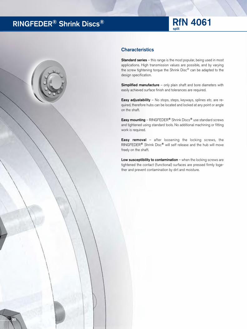
Standard series – this range is the most popular, being used in most applications. High transmission values are possible, and by varying the screw tightening torque the Shrink Disc® can be adapted to the design specification.
Simplified manufacture – only plain shaft and bore diameters with easily achieved surface finish and tolerances are required.
Easy adjustability – No stops, steps, keyways, splines etc. are re-quired, therefore hubs can be located and locked at any point or angle on the shaft.
Easy mounting – RINGFEDER® Shrink Discs® use standard screws and tightened using standard tools. No additional machining or fitting work is required.
Easy removal – after loosening the locking screws, the RINGFEDER® Shrink Disc® will self release and the hub will move freely on the shaft.
Low susceptibility to contamination – when the locking screws are tightened the contact (functional) surfaces are pressed firmly toge-ther and prevent contamination by dirt and moisture.
30

RfN 4061 split
Size Transmissibletorques oraxial forces
Locking screwsDIN EN ISO 4014-10.9
Weight
dw Cw d Ch D L2 d1 B±0.039 R1 max TA Quantity Thread WT TmaxT Fax
Inch Inch Inch Inch Inch Inch Inch Inch Inch lb-ft lb-ft lbs n lbs lb-ft
2.362
0.0019+0
-0.0021
37991 3172 348985 3.346 6.102 0.512 4.488 0.906 0.130 22 10 M8 7.7 2.756 47658 4861 5347 2.559 38216 3503 385490 3.543 6.102 0.551 4.488 0.906 0.130 22 10 M8 7.3 2.953 47208 5347 5882 2.559 43836 3968 436595 3.740 6.693 0.551 4.882 0.925 0.130 22 12 M8 10.4 2.953 53952 6048 6653 2.756 43836 5089 5598
100 3.937 6.693 0.669 4.882 1.004 0.130 22 12 M8 10.4 3.150 53952 6638 7302 2.953 51479 5310 5841
110 4.331 7.283 0.669 5.354 1.122 0.189 44 9 M10 13.0 3.346 58898 7966 8762 3.150
0.0027
+0 -0.0025
60696 6786 7464115 4.528 7.283 0.748 5.591 1.260 0.189 44 10 M10 13.2 3.740 74184 11063 12170 3.346 77556 8113 8924
125 4.921 8.465 0.748 6.299 1.260 0.189 44 12 M10 18.3 3.740 77781 11063 12170 3.740 7418 11137 12251
140 5.512 9.055 0.866 6.890 1.398 0.189 74 10 M12 22.1 4.134 74409 14825 16307 4.134 71936 16226 17849
155 6.102 10.433 1.102 3.622 1.467 0.189 74 12 M12 33.1 4.528 72386 20652 22717 4.528
+0 -0.0025
22864 133756 25151165 6.496 11.417 1.220 8.268 1.594 0.189 184 8 M16 48.5 4.921 28765 147244 31641 4.921
0.0031
26552 136004 29207175 6.890 11.811 1.220 8.661 1.594 0.189 184 8 M16 48.5 5.315 33190 151740 36509 5.315
+0 -0.0028
38353 174894 42188185 7.283 12.992 1.496 9.291 1.890 0.189 184 10 M16 81.6 5.709 45729 193553 50302 5.512 47941 209738 52736
195 7.677 13.780 1.496 9.685 1.890 0.189 184 12 M16 90.4 6.102 60111 240761 66122 5.906 54579 222552 60037
200 7.874 13.780 1.496 9.685 1.890 0.189 184 12 M16 90.4 6.299 63430 242784 69773
31
RINGFEDER® Shrink Discs® RfN 4071Standard Series
Characteristics
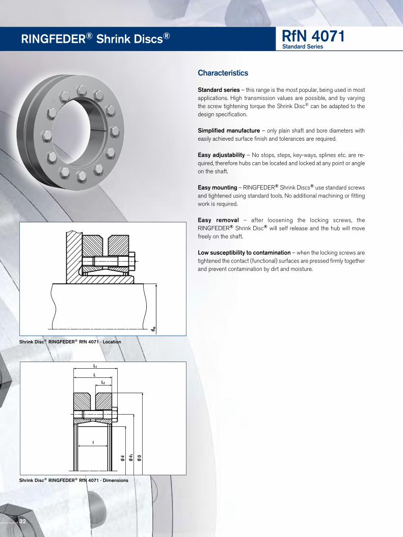
Standard series – this range is the most popular, being used in most applications. High transmission values are possible, and by varying the screw tightening torque the Shrink Disc® can be adapted to the design specification.
Simplified manufacture – only plain shaft and bore diameters with easily achieved surface finish and tolerances are required.
Easy adjustability – No stops, steps, key-ways, splines etc. are re-quired, therefore hubs can be located and locked at any point or angle on the shaft.
Easy mounting – RINGFEDER® Shrink Discs® use standard screws and tightened using standard tools. No additional machining or fitting work is required.
Easy removal – after loosening the locking screws, the RINGFEDER® Shrink Disc® will self release and the hub will move freely on the shaft.
Low susceptibility to contamination – when the locking screws are tightened the contact (functional) surfaces are pressed firmly together and prevent contamination by dirt and moisture.
Shrink Disc® RINGFEDER® RfN 4071 · Location
Shrink Disc® RINGFEDER® RfN 4071 · Dimensions
32

RfN 4071 Standard Series
Size Shrink Disc® dimensions Transmissibletorques or
axial forces
Locking screws Weight
DIN EN ISO 4014-10.9
dw Cw d Ch D L1 L d1 L2 I TA P σvQuantity Thread Tmax T Fax
Inch Inch Inch Inch Inch Inch Inch Inch Inch Inch lb-ft lb-ft lbs psi n lbs lb-ft
6.299
0.0031+0
-0.0028
70068 267512 42775 87585220 8.661 14.567 4.488 4.094 10.630 1.850 3.465 184 35960 15 M16x80 119 6.693 81132 289992 43935 101415 6.693 88507 329107 44805 110634
240 9.449 15.945 4.803 4.291 11.614 1.929 3.622 361 39440 12 M20x80 148 7.480 115059 376540 48430 143824 7.480
0.0035
+0 -0.0032
120960 395648 44370 151200260 10.236 16.929 5.236 4.724 12.638 2.126 4.055 361 37990 14 M20x90 181 8.268 151200 451848 47705 189000 8.268 160051 469832 42775 200063
280 11.024 18.110 5.787 5.276 13.622 2.362 4.488 361 36395 16 M20x100 225 9.055 199141 528280 46980 248927 9.055 202829 546489 42195 253536
300 11.811 19.094 6.102 5.591 14.331 2.520 4.803 361 35670 18 M20x100 260 9.646 232331 592573 45240 290414 9.449
+0 -0.0035
230119 595046 42485 287648320 12.598 20.472 6.102 5.591 15.197 2.520 4.803 361 37265 20 M20x100 289 10.236 275847 651920 46400 344809 9.843
0.0040
287648 701151 42775 359561340 13.386 22.441 6.654 6.142 16.063 2.795 5.276 361 38280 24 M20x110 410 10.630 339278 764320 45965 424097 10.630 326002 736445 41905 407502
350 13.780 22.835 6.890 6.378 17.008 2.874 5.512 361 35525 24 M20x110 430 11.220 368780 786800 44515 460975 11.024 341490 744088 40890 426863
360 14.173 23.228 6.890 6.378 17.008 2.874 5.512 361 34510 24 M20x110 450 11.614 385006 794893 43210 481258 11.417 418197 878968 43500 522746
380 14.961 25.394 7.205 6.614 18.031 2.992 5.669 620 38135 20 M24x120 527 12.205 485314 954950 46400 606643 11.811 460237 935168 44225 575297
390 15.354 25.984 7.205 6.614 18.425 2.992 5.669 620 39150 21 M24x120 573 12.598 529568 1008003 47995 661960 12.402
0.0044
494165 957648 43790 617707400 15.748 26.772 7.205 6.614 18.898 2.992 5.669 620 38135 21 M24x120 617 12.992 548745 1011600 46980 685931 12.992
+0 -0.0038
575297 1090280 42775 719121420 16.535 27.165 7.992 7.402 19.843 3.386 6.457 620 36395 24 M24x130 697 13.780 663804 1173456 46690 829755 13.386 594473 1065552 38715 743092
440 17.323 29.528 8.543 7.953 20.748 3.583 6.969 620 32335 24 M24x140 900 14.173 676343 1144232 41325 845428 14.173 737560 1274616 42485 921950
460 18.110 30.315 8.543 7.953 21.535 3.583 6.969 620 35960 43645 28 M24x140 926 14.961 - 1360040 45530 - 14.961 862945 1382520 40890 -
480 18.898 31.496 8.976 8.386 22.441 3.780 7.402 620 34800 30 M24x140 1114 15.748 966204 1472440 44370 - 15.748
0.0048967679 1474688 41180 -
500 19.685 33.465 9.055 8.386 23.228 3.780 7.402 922 35090 24 M27x150 1268 16.535 - 1557864 45095 -
33

RINGFEDER® Shrink Discs® RfN 4071split
Split Shrink Discs®
In the application shown above special screws according to the dimension X are required, which have to be ordered accordingly. If the dimension X is above 2 x L (L taken from the Standard and the Light Duty Series) or above 1 x L (taken from the Heavy Duty Series) the transmissible torque may be reduced by up to 50%.
Half Shrink Discs®
With half shrink discs® HC/HT only 50% of stated T is transmitted.
type HT (Threaded holes in thrust ring)
type HC (Clearance holes in thrust ring)
Shrink Disc® RINGFEDER® RfN 4071 split · Location
D d1 d dw
R1max
L2
B x
Shrink Disc® RINGFEDER® RfN 4071 HC · Dimensions
D d1 d dw
R1max
L2
B x
D d1 d dw
R1max
L2
B x
Shrink Disc® RINGFEDER® RfN 4071 HT version
34

RfN 4071 split
Size Shrink Disc® dimensions Transmissibletorques oraxial forces
Locking screwsDIN EN ISO 4014-10.9
Weight
dw Cw d Ch D L2 d1 B±0.039 R1 max TA Quantity Thread WT TmaxT Fax
Inch Inch Inch Inch Inch Inch Inch Inch Inch lb-ft lb-ft lbs n lbs lb-ft
6.299
0.0031+0
-0.0028
70068 267512 77075220 8.661 14.567 1.850 10.630 2.343 0.291 184 15 M16 119 6.693 81132 289992 89245 6.693 88507 329107 97358
240 9.449 15.945 1.929 11.614 2.441 0.291 361 12 M20 148 7.480 115059 376540 126565 7.480
0.0035
+0 -0.0032
120960 395648 133056260 10.236 16.929 2.126 12.638 2.657 0.291 361 14 M20 181 8.268 151200 451848 166320 8.268 160051 469832 176056
280 11.024 18.110 2.362 13.622 3.012 0.331 361 179965 499056 16 M20 225 197961 9.055 199141 528280 219055 9.055 202829 546489 223112
300 11.811 19.094 2.520 14.331 3.130 0.331 361 18 M20 260 9.646 232331 592573 255565 9.449
+0 -0.0035
230119 595046 253131320 12.598 20.472 2.520 15.197 3.130 0.331 361 20 M20 289 10.236 275847 651920 303432 9.843
0.0040
287648 701151 316413340 13.386 22.441 2.795 16.063 3.406 0.331 361 24 M20 410 10.630 339278 764320 373205 10.630 326002 736445 358602
350 13.780 22.835 2.874 17.008 3.524 0.331 361 24 M20 430 11.220 368780 786800 405658 11.024 341490 744088 375639
360 14.173 23.228 2.874 17.008 3.524 0.331 361 24 M20 450 11.614 385006 794893 423507 11.417 418197 878968 460016
380 14.961 25.394 2.992 18.031 3.642 0.331 620 20 M24 527 12.205 485314 954950 533846 11.811 460237 935168 506261
390 15.354 25.984 2.992 18.425 3.642 0.331 620 21 M24 573 12.598 529568 1008003 582525 12.402
0.0044
494165 957648 543582400 15.748 26.772 2.992 18.898 3.642 0.331 620 21 M24 617 12.992 548745 1011600 603619 12.992
+0 -0.0038
575297 1090280 632826420 16.535 27.165 3.386 19.843 4.193 0.390 620 24 M24 697 13.780 663804 1173456 730184 13.386 594473 1065552 653921
440 17.323 29.528 3.583 20.748 4.469 0.390 620 24 M24 900 14.173 676343 1144232 743977 14.173 737560 1274616 811316
460 18.110 30.315 3.583 21.535 4.469 0.390 620 28 M24 926 14.961 1032584 1360040 1135842 14.961 862945 1382520 949240
480 18.898 31.496 3.780 22.441 4.685 0.390 620 30 M24 1114 15.748 966204 1472440 1062824 15.748
0.0048967679 1474688 1064447
500 19.685 33.465 3.780 23.228 4.685 0.390 922 24 M27 1268 16.535 1073150 1557864 1180465
35

Shrink Disc® RINGFEDER® RfN 4073 · Location
Worm gear (metric example)
Shrink Disc® RINGFEDER® · Dimensions
RINGFEDER® Shrink Discs® RfN 4073Ultra Light Duty Series
36

To continue see next page
RfN 4073 Ultra Light Duty Series
Size Shrink Disc® dimensions Transmissibletorques oraxial forces
Locking screwsDIN EN ISO 4014-10.9
Weight
dw Cw d Ch D L1 L d1 L2 I TA P σv Quantity Thread WT TmaxT Fax
Inch Inch Inch Inch Inch Inch Inch Inch Inch Inch lb-ft lb-ft lbs psi n lbs lb-ft
0.354
0.0007
+0 -0.0013
6.6 562 56405 1314 0.551 1.339 0.551 0.472 0.945 0.197 0.354 1.8 28130 3 M4x10 0.2 0.433 15 1034 52345 26 0.433 24 1619 59160 3016 0.630 1.654 0.583 0.472 1.181 0.197 0.354 1.8 38280 4 M4x10 0.2 0.512 38 2226 63800 47 0.551 30 1641 44950 3820 0.787 1.850 0.689 0.551 1.339 0.236 0.394 2.2 27985 4 M5x12 0.3 0.630 46 2158 46400 58 0.630 50 2360 46400 6322 0.866 1.969 0.728 0.591 1.457 0.256 0.394 2.2 31755 5 M5x12 0.4 0.709 69 2922 49445 87 0.709 60 2473 42630 7424 0.945 2.047 0.728 0.591 1.535 0.256 0.394 2.2 29145 5 M 5x12 0.4 0.787 77 2922 48430 97 0.787 57 2158 39150 7128 1.102 2.205 0.728 0.591 1.693 0.256 0.394 2.2 24940 5 M 5x12 0.4 0.945 97 3035 41905 122 0.945 81 2473 35380 10231 1.220 2.362 0.728 0.591 1.811 0.256 0.394 2.2 22620 5 M 5x12 0.4 1.063 114 3147 38280 142 1.102
+0 -0.0015
119 3147 33785 14836 1.417 2.598 0.728 0.591 2.047 0.256 0.394 2.2 23345 6 M 5x12 0.5 1.260 159 3709 47560 198 1.299
0.0013
195 4496 47125 24440 1.575 2.677 0.728 0.591 2.165 0.256 0.394 3.0 28130 6 M 5x12 0.5 1.378 236 5058 48720 292 1.496 295 5845 40310 37146 1.811 3.150 0.886 0.748 2.480 0.315 0.551 3.0 23200 8 M 5x16 1.0 1.654 406 7306 47270 504 1.654 325 5845 36105 40651 2.008 3.386 0.886 0.748 2.697 0.315 0.551 3.0 20880 8 M 5x16 1.1 1.772 406 6744 37845 502 1.811
+0 -0.0018
413 6744 34945 50956 2.205 3.583 0.886 0.748 2.874 0.315 0.551 3.0 21460 9 M 5x16 1.1 1.969 524 7868 37410 656 2.047 524 7643 41325 65661 2.402 3.780 0.886 0.748 3.031 0.315 0.551 3.0 21895 10 M 5x16 1.2 2.205 671 8992 44805 833 2.283
0.0019
627 8205 38570 78966 2.598 3.937 0.886 0.748 3.228 0.315 0.551 3 20300 10 M 5x16 1.3 2.441 782 9554 44660 974 2.441 1040 12701 40455 130570 2.756 4.331 1.083 0.945 3.543 0.394 0.709 4.4 22185 10 M5x20 2.1 2.559 1202 14050 46690 1505 2.598 1092 12364 37120 135775 2.953 4.488 1.083 0.945 3.661 0.394 0.709 4.4 20590 10 M5x20 2.1 2.756 1305 14162 43645 1630 2.795 1475 15736 39005 184480 3.150 4.724 1.083 0.945 3.976 0.394 0.709 4.4 23345 12 M5x20 2.3 2.953 1719 17422 47705 2154 2.992
+0 -0.0021
1748 17422 35670 218385 3.346 5.039 1.260 1.102 4.134 0.453 0.866 9 19865 8 M6x25 3.1 3.150 2036 19333 45820 2545 3.228 1696 15624 36685 211794 3.701 5.512 1.260 1.102 4.685 0.453 0.866 9 17980 8 M6x25 3.7 3.465 2154 18658 41905 2699 3.622 2213 18209 34655 2766
105 4.134 5.906 1.260 1.102 5.039 0.453 0.866 9 18125 9 M6x25 3.9 3.858 2714 21019 38570 3393
37

Characteristics
Ultra Light Duty Series – this range is a very compact design with low inertia values. It is ideally suited for mechanical seal and small gearbox applications.
Simplified manufacture – only plain shaft and bore diameters with easily achieved surface finish and tolerances are required.
Easy adjustability – No stops, steps, keyways, splines etc. are required therefore hubs can be located and locked at any point or angle on the shaft.
Easy mounting – RINGFEDER® Shrink Discs® use standard screws and tightened using standard tools. No additional machi-ning or fitting work is required.
Easy removal– after loosening the locking screws, the RINGFEDER® Shrink Disc® will self release and the hub will move freely on the shaft.
Low susceptibility to contamination – when the locking screws are tightened the contact (functional) surfaces are pressed firmly together and prevent contamination by dirt and moisture.
RINGFEDER® Shrink Discs® RfN 4073Ultra Light Duty Series
38

More sizes on request
RfN 4073 Ultra Light Duty Series
Size Shrink Disc® dimensions Transmissibletorques oraxial forces
Locking screwsDIN EN ISO 4014-10.9
Weight
dw Cw d Ch D L1 L d1 L2 I TA P σv Quantity Thread WT TmaxT Fax
Inch Inch Inch Inch Inch Inch Inch Inch Inch lb-ft lb-ft lbs psi n lbs lb-ft
3.9370.0019
+0 -0.0021
2500 18996 32625 3127112 4.409 6.220 1.260 1.102 5.315 0.453 0.866 9 16965 9 M6x25 4.2 4.173 3024 21581 38280 3776 4.173
0.0027+0
-0.0025
2876 20569 30160 3592120 4.724 6.457 1.417 1.260 5.551 0.512 0.984 9 15515 10 M6x25 4.9 4.409 3444 23379 33350 4300 3.937 3135 22255 27695 3924
130 5.118 6.772 1.417 1.260 5.945 0.512 0.984 9 14355 10 M6x25 4.9 4.173 3762 23379 32625 4706 4.921 4197 30348 30160 5244
140 5.512 7.165 1.417 1.260 6.339 0.512 0.984 9 15950 12 M 6x25 5.3 5.118 4757 27875 31900 5945 5.315 4632 26077 28130 5782
150 5.906 7.638 1.417 1.260 6.732 0.512 0.984 9 14935 12 M6x25 6.0 5.512 5200 28100 29870 6498 5.591 4691 24953 25955 5856
160 6.299 8.031 1.417 1.260 7.126 0.512 0.984 9 13920 12 M6x25 6.25.827 5355 27426 27115 6690
39

Shrink Disc® RINGFEDER® RfN 4091 · Location
Lever · metric example
Shrink Disc® RINGFEDER® RfN 4091 · Dimensions
RINGFEDER® Shrink Discs® RfN 4091Heavy Duty Series
40

To continue see next page
RfN 4091 Heavy Duty Series
Size Shrink Disc® dimensions Transmissibletorques oraxial forces
Locking screwsDIN EN ISO 4014-10.9
Weight
dw Cw d Ch D L1 L d1 L2 I TA P σv Quantity Thread WT TmaxT Fax
mm Inch Inch Inch Inch Inch Inch Inch Inch Inch Inch lb-ft lb-ft lbs psi n lbs lb-ft
38 1.496
0.0013
+0 -0.0015
1328 23829 59450 166050 40 1.969 3.740 1.752 1.535 2.874 0.669 1.181 18 41325 7 M8x35 3.1 42 1.654 1770 27875 74095 2213 42 1.654
+0 -0.0018
1660 27426 58580 207555 45 2.165 4.134 1.752 1.535 3.071 0.669 1.181 21 42050 7 M8x35 3.7 48 1.890 2360 33270 83230 2950 48 1.890 2176 30123 54520 272062 62 2.441 4.528 1.752 1.535 3.346 0.669 1.181 22 40020 7 M8x35 4.4 52 2.047 2655 32596 66410 3319 50 1.969
0.0019
2360 32596 52345 295068 55 2.677 4.724 1.752 1.535 3.622 0.669 1.181 22 41615 8 M8x35 4.6 58 2.283 3835 40914 78155 4794 55 2.165 3393 43386 58435 424175 60 2.953 5.709 2.087 1.811 4.134 0.787 1.417 44 43790 7 M10x40 8.4 65 2.559 5163 55975 78300 6454 60 2.362 4204 44960 54955 525580 65 3.150 5.709 2.087 1.811 4.134 0.787 1.417 44 5163 41035 7 M10x40 7.9 70 2.756 6196 56874 73950 7744 65 2.559
+0 -0.0021
4942 48782 49155 617790 70 3.543 6.299 2.244 1.969 4.567 0.866 1.575 44 37555 8 M10x40 11 75 2.953 7081 60471 57275 8851 70 2.756 6491 59572 48430 8113
100 75 3.937 6.693 2.402 2.126 4.961 0.906 1.732 44 38425 10 M10x45 12 80 3.150 8998 72161 53360 11248 75 2.953 8113 69238 45820 10141
110 80 4.331 7.283 2.638 2.362 5.433 1.024 1.969 44 36830 12 M10x45 17 85 3.346 10842 79130 52200 13553 85 3.346
0.0027
+0 -0.0025
11063 79804 47995 13829125 90 4.921 8.465 2.874 2.559 6.299 1.102 2.165 74 35960 10 M12x50 24 95 3.740 14751 94866 48865 18439 90 3.543 12391 94416 47560 15489
135 95 5.315 8.346 3.268 2.953 6.693 1.260 2.362 74 36250 12 M12x55 23 105 4.134 18365 119144 48720 22953 95 3.740 15194 97338 45385 18992
140 100 5.512 9.055 3.228 2.913 6.890 1.260 2.362 74 35235 12 M12x55 29 105 4.134 19545 112400 46110 24432 90 3.543 29355 198948 60030 36694
140 100 5.512 11.969 4.173 3.780 7.283 1.654 3.150 184 49735 12 M16x70 77 110 4.331 46909 258520 74385 58636 105 4.134 19914 122741 44950 24893
155 110 6.102 10.354 3.543 3.228 7.795 1.378 2.598 74 36250 15 M12x60 43 115 4.528 25077 140275 45530 31346 115 4.528 30240 166352 46980 37800
165 120 6.496 11.417 3.858 3.465 8.268 1.496 2.835 184 39150 10 M16x65 57 125 4.921 37394 183212 49880 46743 125 4.921
0.0031
34665 168600 45820 43332175 130 6.890 11.811 3.858 3.465 8.661 1.496 2.835 184 36830 10 M16x65 64 135 5.315 42041 188832 47125 52551 125 4.921 51629 260768 53070 64537
175 130 6.890 11.811 4.961 4.567 9.252 1.969 3.622 184 43500 15 M16x80 81 135 5.315 62693 289992 55680 78366 135 5.315
+0 -0.0028
53104 247280 47415 66380185 140 7.283 12.992 4.803 4.409 9.291 1.969 3.622 184 38135 14 M16x80 104 145 5.709 63430 269760 50025 88507 135 5.315 66602 316743 55970 83248
190 140 7.480 13.780 4.921 4.409 9.843 1.969 3.622 347 47850 12 M20x90 115 155 6.102 91457 378788 63800 114322 140 5.512 55317 241660 44950 78366
195 150 7.677 13.780 4.803 4.409 9.685 1.969 3.622 184 36250 14 M16x80 117 155 6.102 70806 277628 47850 92195
41

Characteristics
Highest transmission values – for heavy duty applications.
Simplified manufacture – only plain shaft and bore diameters with easily achieved surface finish and tolerances are required.
Easy adjustability – No stops, steps, keyways, splines etc. are re-quired therefore hubs can be located and locked at any point or angle on the shaft.
Easy mounting – RINGFEDER® Shrink Discs® use standard screws and tightened using standard tools. No additional machi-ning or fitting work is required.
Easy removal – after loosening the locking screws, the RINGFEDER® Shrink Disc® will self release and the hub will move freely on the shaft.
Low susceptibility to contamination – when the locking screws are tightened the contact (functional) surfaces are pressed firmly together and prevent contamination by dirt and moisture.
Highest reliability – due to the materials chosen and manufacturing processes used, RINGFEDER® Shrink Discs® can be tightened and released as often as required. If locking screws need replacing, they are standard items and thus easily available.
RINGFEDER® Shrink Discs® RfN 4091Heavy Duty Series
42

More sizes on request
RfN 4091 Heavy Duty Series
Size Transmissibletorques oraxial forces
Locking screwsDIN EN ISO 4014-10.9
Weight
dw Cw d Ch D L1 L d1 L2 I TA P σv Quantity Thread WT TmaxT Fax
Inch Inch Inch Inch Inch Inch Inch Inch Inch Inch lb-ft lb-ft lbs psi n lbs lb-ft
5.709
+0 -0.0028
62693 712616 45965 117088200 7.874 13.780 4.803 4.409 9.685 1.969 3.622 184 37845 15 M16x80 110 6.102 73756 741840 47850 135066 6.299 93670 357432 44805 142902
220 8.661 14.567 5.669 5.276 10.630 2.362 4.488 184 36975 20 M16x90 143 6.693 108053 386656 47125 182546 6.693
0.0031+0
-0.0028
114322 409136 44225 196375240 9.449 15.945 6.181 5.669 11.614 2.559 4.724 361 37845 15 M20x100 192 7.480 146037 467584 49445 247083 7.480
0.0035
+0 -0.0032
157100 508048 44660 262756260 10.236 16.929 6.811 6.299 12.638 2.835 5.354 361 36975 18 M20x110 220 8.268 197666 579984 50170 327292 8.268 210205 615952 44950 314385
280 11.024 18.110 7.283 6.772 13.622 3.071 5.827 361 36830 21 M20x120 291 9.055 261834 694632 51620 363248 9.055 251508 665408 43210 314385
300 11.811 19.094 7.441 6.929 14.331 3.150 5.984 361 35090 22 M20x120 309 9.646 290599 722732 47415 363248 9.449
+0 -0.0035
278798 708120 40890 348497320 12.598 20.472 7.756 7.244 15.197 3.228 6.299 361 34075 24 M20x130 364 10.236 332640 780056 46110 415799 9.843
0.0040
361036 878968 42775 451295340 13.386 22.441 8.465 7.874 16.535 3.622 6.929 620 36685 21 M24x130 529 10.630 426310 961020 47270 532887 10.630 410083 926626 44080 512604
350 13.780 22.835 8.465 7.874 16.732 3.622 6.929 620 35815 21 M24x130 544 11.220 463925 992492 47995 579907 11.024 451387 982376 43935 564233
360 14.173 23.228 8.622 8.031 17.008 3.622 7.087 620 35525 22 M24x140 551 11.614 508179 1049816 48140 635224 11.417 455812 959896 40455 569765
380 14.961 25.394 8.622 8.031 18.031 3.622 7.087 620 33785 22 M24x140 705 12.205 530306 1044196 44515 662882 11.811 522192 1059932 41180 652741
390 15.354 25.984 8.937 8.346 18.425 3.780 7.402 620 34220 24 M24x140 771
12.598 600743 1144232 46110 750836 12.402
0.0044
564233 1091404 41325 705292400 15.748 26.772 8.937 8.346 18.898 3.780 7.402 620 33495 24 M24x140 815 12.992 623238 1152100 45240 779048 12.992
+0 -0.0038
736822 1361164 43790 921028420 16.535 27.165 9.961 9.370 19.843 4.370 8.425 620 34945 30 M24x150 904 13.780 840818 1464572 49590 1051023 13.386 780338 1400504 41035 975423
440 17.323 29.528 10.591 9.921 20.748 4.528 8.819 922 33495 24 M27x170 1190 14.173 888022 1503912 45240 1110028 14.173 973579 1672512 45240 1216974
460 18.110 30.315 10.591 9.921 21.535 4.528 8.819 922 37265 28 M27x170 1190 14.961 1106340 1787160 50170 1382925 14.961 1132155 1816384 43790 1415193
480 18.898 31.496 11.457 10.787 22.835 5.039 9.685 922 34945 30 M27x180 1433 15.748 1268603 1933280 49300 1585754 15.748
0.00481290730 1967000 44805 1613413
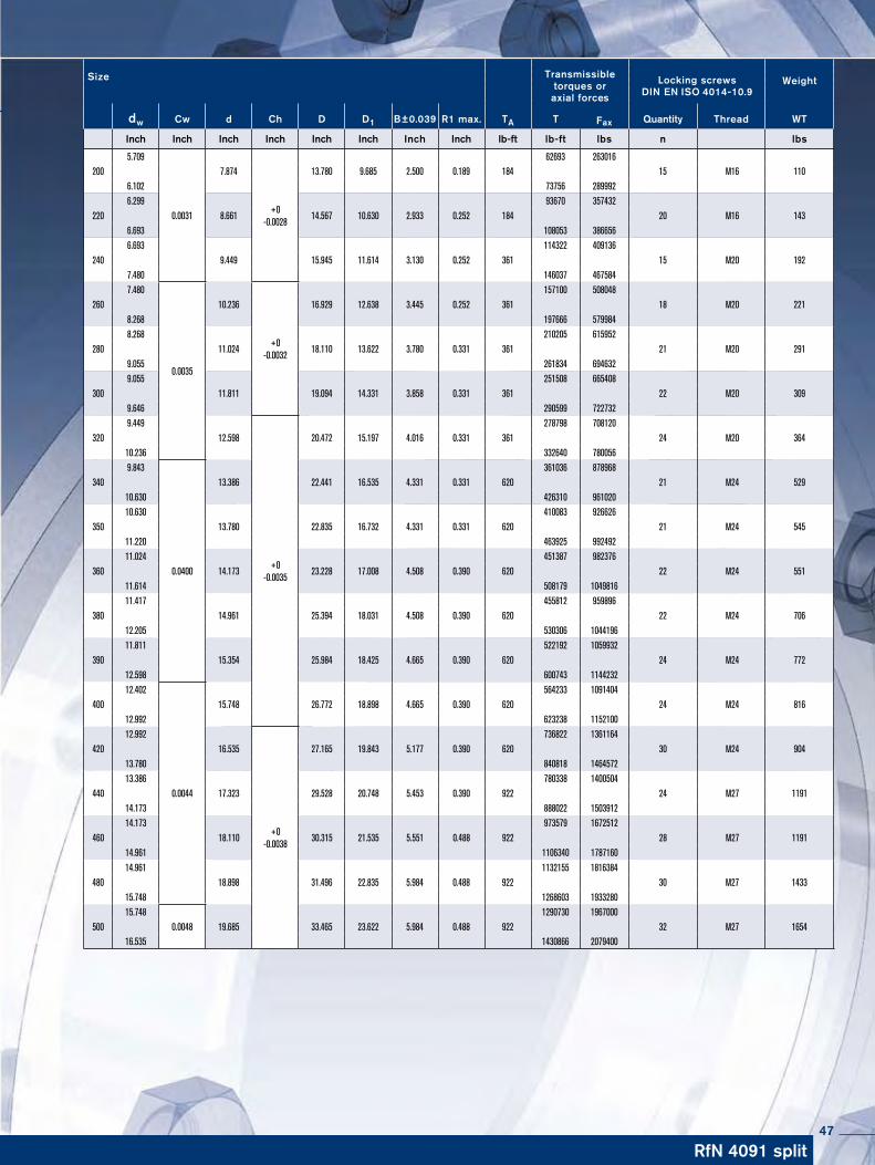
500 19.685 33.465 11.457 10.787 23.622 5.039 9.685 922 35670 32 M27x180 165316.535 1430866 2079400 50750 1788583
43
Shrink Disc® RINGFEDER® RfN 4091 · Location
Shrink Disc® RINGFEDER® RfN 4091 HT
Shrink Disc® RINGFEDER® RfN 4091 HC · Dimensions
RINGFEDER® Shrink Discs® RfN 4091split
D d1 d dw
R1max
L2
B x
D d1 d dw
R1max
L2
B x
D d1 d dw
R1max
L2
B x
Split Shrink Discs®
In the application shown above special screws according to the dimension X are required, which have to be ordered accordingly. If the dimension X is above 2 x L (L taken from the Standard and the Light Duty Series) or above 1 x L (taken from the Heavy Duty Series) the transmissible torque may be reduced by up to 50%.
Half Shrink Discs®
With half shrink discs® HC/HT only 50% of stated T is transmitted.
type HT (Threaded holes in thrust ring)
type HC (Clearance holes in thrust ring)
44

RfN 4091 split
To continue see next page
Size Transmissibletorques oraxial forces
Locking screwsDIN EN ISO 4014-10.9
Weight
dw Cw d Ch D D1 B±0.039 R1 max. TA T Fax Quantity Thread WT
Inch Inch Inch Inch Inch Inch Inch Inch lb-ft lb-ft lbs n lbs
1.496
0.0013
+0 -0.0015
1328 23829 50 1.969 3.740 2.874 0.906 0.071 18 7 M8 3.1 1.654 1770 27875 1.654
+0 -0.0018
1660 27426 55 2.165 4.134 3.071 0.906 0.071 21 7 M8 3.7 1.890 2360 33270 1.890 2176 30123 62 2.441 4.528 3.346 0.906 0.071 22 7 M8 4.4 2.047 2655 32596 1.969
0.0019
2360 32596 68 2.677 4.724 3.622 0.906 0.071 22 8 M8 4.6 2.283 3835 40914 2.165 3172 43386 75 2.953 5.709 4.134 1.063 0.110 44 7 M10 8.4 2.559 516 55975 2.362 4204 44960 80 3.150 5.709 4.134 1.063 0.110 44 7 M10 7.9 2.756 6196 56874 2.559
+0 -0.0021
4942 48782 90 3.543 6.299 4.567 1.142 0.110 44 8 M10 11 2.953 7081 60471 2.756 6491 59572
100 3.937 6.693 4.961 1.260 0.130 44 10 M10 12 3.150 8998 72161 2.953 8113 69238
110 4.331 7.283 5.433 1.378 0.130 44 12 M10 17 3.346 10842 79130 3.346
0.0027
+0 -0.0025
11063 79804 125 4.921 8.465 6.299 1.476 0.130 74 10 M12 24 3.740 14751 94866 3.543 12391 94416
135 5.315 8.346 6.693 1.772 0.189 74 12 M12 23 4.134 18365 119144 3.740 15194 97338
140 5.512 9.055 6.890 1.654 0.189 74 12 M12 29 4.134 19545 112400 3.543 29355 198948
140 5.512 11.969 7.283 2.126 0.189 184 12 M16 77 4.331 46909 258520 4.134 19914 122741
155 6.102 10.354 7.795 1.772 0.189 74 15 M12 43 4.528 25077 140275 4.528 30240 166352
165 6.496 11.417 8.268 1.929 0.189 184 10 M16 57 4.921 37394 183212 4.921
0.0031
34665 168600 175 6.890 11.811 8.661 1.929 0.189 184 10 M16 64 5.315 42041 188832 4.921 51629 260768
175 6.890 11.811 9.252 2.323 0.189 184 15 M16 81 5.315 62693 289992 5.315
+0 -0.0028
53104 247280 185 7.283 12.992 9.291 2.402 0.189 184 14 M16 104 5.709 70806 269760 5.315 66602 316743
190 7.480 13.780 9.843 2.441 0.189 347 12 M20 115 6.102 91457 378788 5.512 55317 241660
195 7.677 13.780 9.685 2.500 0.189 184 14 M16 117 6.102 70806 277628
45

RINGFEDER® Shrink Discs® RfN 4091split
D d1 d dw
R1max
L2
B x
D d1 d dw
R1max
L2
B x
D d1 d dw
R1max
L2
B x
Shrink Disc® RINGFEDER® RfN 4091 · Location
Shrink Disc® RINGFEDER® RfN 4091 HT
Shrink Disc® RINGFEDER® RfN 4091 HC · Dimensions
46
RfN 4091 split
Size Transmissibletorques oraxial forces
Locking screwsDIN EN ISO 4014-10.9
Weight
dw Cw d Ch D D1 B±0.039 R1 max. TA T Fax Quantity Thread WT
Inch Inch Inch Inch Inch Inch Inch Inch lb-ft lb-ft lbs n lbs
5.709
0.0031+0
-0.0028
62693 263016 200 7.874 13.780 9.685 2.500 0.189 184 15 M16 110 6.102 73756 289992 6.299 93670 357432
220 8.661 14.567 10.630 2.933 0.252 184 20 M16 143 6.693 108053 386656 6.693 114322 409136
240 9.449 15.945 11.614 3.130 0.252 361 15 M20 1927.480 146037 467584
7.480
0.0035
+0 -0.0032
157100 508048 260 10.236 16.929 12.638 3.445 0.252 361 18 M20 221 8.268 197666 579984 8.268 210205 615952
280 11.024 18.110 13.622 3.780 0.331 361 21 M20 291 9.055 261834 694632 9.055 251508 665408
300 11.811 19.094 14.331 3.858 0.331 361 22 M20 309 9.646 290599 722732 9.449
+0 -0.0035
278798 708120 320 12.598 20.472 15.197 4.016 0.331 361 24 M20 364 10.236 332640 780056 9.843
0.0400
361036 878968 340 13.386 22.441 16.535 4.331 0.331 620 21 M24 529 10.630 426310 961020 10.630 410083 926626
350 13.780 22.835 16.732 4.331 0.331 620 21 M24 545 11.220 463925 992492 11.024 451387 982376
360 14.173 23.228 17.008 4.508 0.390 620 22 M24 551 11.614 508179 1049816 11.417 455812 959896
380 14.961 25.394 18.031 4.508 0.390 620 22 M24 706 12.205 530306 1044196 11.811 522192 1059932
390 15.354 25.984 18.425 4.665 0.390 620 24 M24 772 12.598 600743 1144232 12.402
0.0044
564233 1091404 400 15.748 26.772 18.898 4.665 0.390 620 24 M24 816 12.992 623238 1152100 12.992
+0 -0.0038
736822 1361164 420 16.535 27.165 19.843 5.177 0.390 620 30 M24 904 13.780 840818 1464572 13.386 780338 1400504
440 17.323 29.528 20.748 5.453 0.390 922 24 M27 1191 14.173 888022 1503912 14.173 973579 1672512
460 18.110 30.315 21.535 5.551 0.488 922 28 M27 1191 14.961 1106340 1787160 14.961 1132155 1816384
480 18.898 31.496 22.835 5.984 0.488 922 30 M27 1433 15.748 1268603 1933280 15.748
0.00481290730 1967000
500 19.685 33.465 23.622 5.984 0.488 922 32 M27 1654 16.535 1430866 2079400
47

Shrink Disc® RINGFEDER® RfN 4161 · Location
Shrink Disc® RINGFEDER® RfN 4161 · Dimensions
RINGFEDER® Shrink Discs® RfN 4161Standard Series
48

RfN 4161 Standard Series
To continue see next page
Size Shrink Disc® dimensions Transmissibletorques oraxial forces
Weight
dw Cw d Ch D L1 L I TA T Fax Thread WT Tmax
mm Inch Inch Inch Inch Inch Inch Inch lb-ft lb-ft lbs lbs lb-ft
0.591
+0 -0.0013
0.0010
59 2473 18 0.630 0.71 1.73 0.75 0.59 0.53 9 81 3147 M6 0.2 89
0.669 111 4047 12220 0.709 0.79 1.85 0.75 0.59 0.53 9 133 4496 M6 0.2 146
0.748 122 3822 13424 0.94 1.97 0.87 0.71 0.59 9 M6 0.4 0.866 218 6070 239 0.787 170 5171 18726 1.02 2.03 0.87 0.71 0.59 9 M6 0.4 0.945 258 6520 284 0.945 273 6969 30030 1.18 2.36 0.94 0.79 0.67 9 M6 0.7 1.024 347 8094 381 1.063
+0 -0.0015
0.0020
354 8094 38936 1.42 2.83 1.08 0.87 0.75 22 M8 1.1 1.299 634 11691 698 1.063 354 8094 38938 1.50 2.83 1.08 0.87 0.75 22 M8 1.1 1.299 634 11691 698 1.339 597 10791 65740 1.57 3.15 1.16 0.94 0.81 22 M8 1.3 1.457 708 11691 779 1.378 597 10342 65744 1.73 3.15 1.16 0.94 0.81 22 M8 1.3 1.457 708 11691 779 1.496 848 13714 93350 1.97 3.54 1.24 1.02 0.87 22 M8 1.8 1.654 1121 16187 1233 1.654
+0 -0.0018
959 13939 105555 2.17 3.94 1.36 1.14 0.96 22 M8 2.4 1.890 1402 17761 1542 1.890 1254 15962 137960 2.36 4.33 1.36 1.14 0.96 22 M8 2.9 2.047 1593 18660 1753 1.890 1254 15962 137962 2.44 4.33 1.36 1.14 0.96 22 M8 2.9 2.047 1593 18660 1753 1.969
0.0023
1402 17086 154268 2.68 4.53 1.38 1.16 0.96 22 M8 2.9 2.362 2324 23606 2556 2.165 1992 22032 219175 2.95 5.43 1.50 1.22 0.98 44 M10 5.1 2.559 3024 28327 3327 2.362 2434 24730 267880 3.15 5.55 1.50 1.22 0.98 44 M10 5.1 2.756 3651 31700 4016 2.559
+0 -0.0021
4057 37995 446385 3.35 6.10 1.77 1.50 1.34 44 M10 7.1 2.953 5827 47437 6410 2.559 4057 37995 446390 3.54 6.10 1.77 1.50 1.24 44 M10 7.1 2.953 5827 47437 6410 2.756 4573 39793 503195 3.74 6.69 1.99 1.71 1.44 44 M10 9.5 3.150 6344 48336 6978 2.756 7745 39793 5031
100 3.94 6.69 1.99 1.71 1.44 44 M10 9.5 3.150 10106 48336 6978
49

RINGFEDER® Shrink Discs® RfN 4161Standard Series
Characteristics
Standard series – this range is the most popular, being used in most applications. High transmission values are possible, and by varying the screw tightening torque the Shrink Disc® can be adapted to the design specification.
Simplified manufacture – only plain shaft and bore diameters with easily achieved surface finish and tolerances are required.
Easy adjustability – No stops, steps, keyways, splines etc. are re-quired, therefore hubs can be located and locked at any point or angle on the shaft.
Easy mounting – RINGFEDER® Shrink Discs® use standard screws and tightened using standard tools. No additional machining or fitting work is required.
Easy removal – after loosening the locking screws, the RINGFEDER® Shrink Disc® will self release and the hub will move freely on the shaft.
Low susceptibility to contamination – when the locking screws are tightened the contact (functional) surfaces are pressed firmly together and contamination by dirt and moisture.
50

RfN 4161 Standard Series
Size Shrink Disc® dimensions Transmissibletorques oraxial forces
Weight
dw Cw d Ch D L1 L I TA T Fax Thread WT Tmax
Inch Inch Inch Inch Inch Inch Inch Inch lb-ft lb-ft lbs lbs lb-ft
3.150
+0 -0.0021
0.0027
7745 59128 8520105 4.13 7.28 2.24 1.93 1.59 74 M12 13 3.543 10106 68345 11116 3.150 7745 59128 8520
110 4.33 7.28 2.24 1.93 1.59 74 M12 133.543 10106 68345 111163.346
+0 -0.0025
0.0027
9220 59128 10142115 4.53 7.76 2.40 2.09 1.77 74 M12 15 3.740 11802 68345 12982 3.346 9220 66097 10142
120 4.72 7.76 2.40 2.09 1.77 74 M12 15 3.740 11802 75764 12982 3.543 10696 72392 11765
125 4.92 8.46 2.42 2.11 1.77 74 M12 19 3.937 13868 84532 15254 3.740 13572 87005 14930
130 5.12 9.06 2.62 2.26 1.85 118 M14 24 4.331 19326 107014 21259 3.740 13572 87005 14930
135 5.31 9.06 2.62 2.26 1.85 118 M14 24 4.331 19326 107014 21259 3.937 14679 89478 16147
140 5.51 9.06 2.64 2.28 1.85 118 M14 23 4.528 20506 108588 22557 4.331 19916 110387 21908
150 5.91 10.35 2.83 2.48 2.01 118 M14 34 4.921 26702 130171 29373 4.331 19916 110387 21908
155 6.10 10.35 2.83 2.48 2.01 118 M14 34 4.921 26702 130171 29373 4.724
0.0031
28768 146133 31645160 6.30 11.42 3.11 2.68 2.20 184 M16 47 5.315 37619 169964 41381 4.724 28768 146133 31645
165 6.50 11.42 3.11 2.68 2.20 184 M16 47 5.315 37619 169964 41381 5.118 34300 160746 37730
170 6.69 11.81 3.15 2.72 2.20 184 M16 50 5.709 43520 183004 47873 5.118 34300 160746 37730
175 6.89 11.81 3.15 2.72 2.20 184 M16 50 5.709 43520 183004 47873 5.512
+0 -0.0028
48684 212005 53552180 7.09 12.60 3.80 3.37 2.81 184 M16 72 6.102 61224 240782 67346 5.512 48684 212005 53552
185 7.28 12.60 3.80 3.37 2.81 184 M16 72 6.102 61224 240782 67346 5.906 60486 245728 66535
190 7.48 13.39 3.80 3.37 2.81 184 M16 82 6.496 75239 277878 82763 5.906 60486 245728 66535
195 7.68 13.39 3.80 3.37 2.81 184 M16 80 6.496 75239 277878 82763 5.906 60486 245728 66535
200 7.87 13.39 3.80 3.37 2.81 184 M16 806.496 75239 277878 82763
51

Shrink Disc® RINGFEDER® RfN 4171 · Location
Shrink Disc® RINGFEDER® RfN 4171 · Dimensions
RINGFEDER® Shrink Discs® RfN 4171Standard Series
Wind turbine
52

RfN 4171 Standard Series
To continue see next page
Shrink Disk dimensionsTransmissible torques or
axial forcesLocking
screws 12.9Weight
d dw D L1 L l TA T Fax WT Tmaxmm Inch lb-ft lb-ft lbs lbs lb-ft
0.591 59 2398 6518 0.630 1.73 0.75 0.59 0.53 9 81 3091 M6 0.2 89
0.669 111 3968 12220 0.709 1.85 0.75 0.59 0.53 9 133 4497 M6 0.2 146
0.748 122 3905 13424 1.97 0.87 0.71 0.59 9 M6 0.4
0.866 218 6030 2390.787 170 5171 187
26 2.03 0.87 0.71 0.59 9 M6 0.40.945 258 6558 2840.945 273 6932 300
30 2.36 0.94 0.79 0.67 9 M6 0.71.024 347 8129 3811.063 354 7994 389
36 2.83 1.08 0.87 0.75 22 M8 1.11.299 634 11718 6981.063 354 7994 389
38 2.83 1.08 0.87 0.75 22 M8 1.11.299 634 11718 6981.339 597 10713 657
40 3.15 1.16 0.94 0.81 22 M8 1.31.457 708 11667 7791.378 597 10406 657
44 3.15 1.16 0.94 0.81 22 M8 1.31.457 708 11667 7791.496 848 13608 933
50 3.54 1.24 1.02 0.87 22 M8 1.81.654 1121 16273 12331.654 959 13918 1055
55 3.94 1.36 1.14 0.96 22 M8 2.41.890 1402 17799 15421.890 1254 15926 1379
60 4.33 1.36 1.14 0.96 22 M8 2.92.047 1593 18678 17531.890 1254 15926 1379
62 4.33 1.36 1.14 0.96 22 M8 2.92.047 1593 18678 17531.969 1402 17087 1542
68 4.53 1.38 1.16 0.96 22 M8 2.92.362 2324 23607 25562.165 1992 22074 2191
75 5.43 1.50 1.22 0.98 44 M10 5.12.559 3024 28363 33272.362 2434 24731 2678
80 5.55 1.50 1.22 0.98 44 M10 5.12.756 3651 31798 40162.559 4057 38048 4463
85 6.10 1.77 1.50 1.34 44 M10 7.12.953 5827 47364 64102.559 4057 38048 4463
90 6.10 1.77 1.50 1.24 44 M10 7.12.953 5827 47364 64102.756 4573 39827 5031
95 6.69 1.99 1.71 1.44 44 M10 9.53.150 6344 48339 69782.756 4573 39827 5031
100 6.69 1.99 1.71 1.44 44 M10 9.53.150 6344 48339 69783.150 7745 59018 8520
105 7.28 2.24 1.93 1.59 74 M12 12.83.543 10106 68449 111163.150 7745 59018 8520
110 7.28 2.24 1.93 1.59 74 M12 12.83.543 10106 68449 111163.346 9220 66127 10142
115 7.76 2.40 2.09 1.77 74 M12 15.23.740 11802 75733 129823.346 9220 66127 10142
120 7.76 2.40 2.09 1.77 74 M12 15.23.740 11802 75733 129823.543 10696 72446 11765
125 8.46 2.42 2.11 1.77 74 M12 19.23.937 13868 84536 152543.740 13572 87092 14930
130 9.06 2.62 2.26 1.85 118 M14 23.84.331 19326 107101 212593.740 13572 87092 14930
135 9.06 2.62 2.26 1.85 118 M14 23.84.331 19326 107101 212593.937 14679 89483 16147
140 9.06 2.64 2.28 1.85 118 M14 22.74.528 20506 108701 22557
53

RINGFEDER® Shrink Discs® RfN 4171Standard Series
Shrink Disc® RINGFEDER® RfN 4171 · Location
Shrink Disc® RINGFEDER® RfN 4171 · Dimensions
54

RfN 4171 Standard Series
Shrink Disk dimensionsTransmissible torques or
axial forcesLocking
screws 12.9Weight
d dw D L1 L l TA T Fax WT Tmaxmm Inch lb-ft lb-ft lbs lbs lb-ft
4.331 19916 110372 21908150 10.35 2.83 2.48 2.01 118 M14 33.5
4.921 26702 130222 293734.331 19916 110372 21908
155 10.35 2.83 2.48 2.01 118 M14 33.54.921 26702 130222 293734.724 28768 146140 31645
160 11.42 3.11 2.68 2.20 184 M16 47.45.315 37619 169872 413814.724 28768 146140 31645
165 11.42 3.11 2.68 2.20 184 M16 47.45.315 37619 169872 413815.118 34300 160841 37730
170 11.81 3.15 2.72 2.20 184 M16 49.65.709 43520 182966 478735.118 34300 160841 37730
175 11.81 3.15 2.72 2.20 184 M16 49.65.709 43520 182966 478735.512 48684 211984 53552
180 12.60 3.80 3.37 2.81 184 M16 726.102 61224 240787 673465.512 48684 211984 53552
185 12.60 3.80 3.37 2.81 184 M16 726.102 61224 240787 673465.906 60486 245815 66535
190 13.39 3.80 3.37 2.81 184 M16 826.496 75239 277973 827635.906 60486 245815 66535
195 13.39 3.80 3.37 2.81 184 M16 806.496 75239 277973 827635.906 60486 245815 66535
200 13.39 3.80 3.37 2.81 184 M16 806.496 75239 277973 827636.299 77452 295091 85197
220 14.57 4.65 4.13 3.46 354 M20 1177.087 101794 344741 1119736.693 92204 330634 101425
240 15.94 4.80 4.29 3.62 354 M20 1467.874 134250 409193 1476757.480 121710 390496 133881
260 16.93 5.24 4.72 4.06 354 M20 1818.661 175557 486453 1931138.268 162280 471075 178508
280 18.11 5.83 5.31 4.49 354 M20 2279.449 221290 562078 2434208.661 202850 562078 223135
300 19.09 6.18 5.59 4.80 627 M24 2659.843 269237 656507 2961609.449 224979 571446 247477
320 20.47 6.18 5.59 4.80 627 M24 30410.630 295054 666166 3245599.843 287678 701473 316445
340 22.44 6.73 6.14 5.28 627 M24 41711.024 376194 819028 41381310.630 365129 824381 401642
350 22.83 7.01 6.42 5.51 627 M24 44511.417 431516 907077 47466810.630 368817 832708 405699
360 23.23 7.09 6.50 5.51 627 M24 45611.811 468398 951785 51523811.417 435205 914830 478725
380 25.20 7.20 6.50 5.67 922 M27 53812.205 505280 993608 55580811.417 479463 1007864 527409
390 25.59 7.24 6.57 5.67 922 M27 54912.598 590108 1124156 64911912.598 547325 1042654 602058
400 25.98 7.99 7.32 6.54 922 M27 62813.780 672723 1171691 73999512.598 547325 1042654 602058
420 26.38 7.99 7.32 6.54 922 M27 62813.780 672723 1171691 73999513.386 697065 1249796 766771
440 29.13 8.31 7.64 6.85 922 M27 86714.567 843117 1389092 92742814.173 814349 1378964 895784
460 30.31 8.31 7.64 6.85 922 M27 92415.354 973678 1521934 107104615.748 958925 1461402 1054818
480 31.50 9.13 8.39 7.52 922 M30 108516.929 1136695 1611464 125036516.929 1103502 1564406 1213852
500 33.46 9.13 8.39 7.52 922 M30 125018.110 1297500 1719469 1427250
55

RINGFEDER® Shrink Discs® RfN 4181Heavy Duty Series
Shrink Disc® RINGFEDER® RfN 4181 · Location
Wind turbine
Shrink Disc® RINGFEDER® RfN 4181 · Dimensions
56

RfN 4181 Heavy Duty Series
Shrink Disk dimensionsTransmissible torques or
axial forcesLocking
screws 12.9Weight
d dw D L1 L l TA T Fax WT Tmaxmm Inch lb-ft lb-ft lbs lbs lb-ft
1.496 1180 18933 M8 129850 3.54 1.24 1.02 0.87 26 1.8
1.654 1475 21412 16231.654 1254 18201 M8 1379
55 3.94 1.36 1.14 0.96 26 2.41.890 1844 23420 20281.890 1697 21546 M8 1866
60 4.33 1.36 1.14 0.96 26 2.92.047 2139 25077 23531.890 1697 21546 M8 1866
62 4.33 1.36 1.14 0.96 26 2.92.047 2139 25077 23531.969 1770 21584 M8 1947
68 4.53 1.38 1.16 0.96 26 2.92.362 2951 29977 32462.165 2803 31068 M10 3083
75 5.43 1.50 1.22 0.98 52 5.12.559 4426 41507 48682.362 3172 32226 M10 3489
80 5.55 1.50 1.22 0.98 52 5.12.756 4795 41754 52742.559 4426 41507 M10 4868
85 6.10 1.77 1.50 1.24 52 7.12.953 6344 51561 69782.559 4426 41507 M10 4868
90 6.10 1.77 1.50 1.24 52 7.12.953 6344 51561 69782.756 5532 48178 M10 6085
95 6.69 1.99 1.71 1.44 52 9.53.150 7819 59580 86012.756 5532 48178 M10 6085
100 6.69 1.99 1.71 1.44 52 9.53.150 7819 59580 86013.150 9442 71946 M12 10386
105 7.28 2.24 1.93 1.59 89 12.83.543 12540 84936 137943.150 9442 71946 M12 10386
110 7.28 2.24 1.93 1.59 89 12.83.543 12540 84936 137943.346 10106 72475 M12 11116
115 7.76 2.40 2.09 1.77 89 15.23.740 13425 86146 147673.346 10106 72475 M12 11116
120 7.76 2.40 2.09 1.77 89 15.23.740 13425 86146 147673.543 12245 82938 M12 13469
125 8.46 2.42 2.11 1.77 89 19.23.937 15859 96677 174453.740 15122 97032 M14 16634
130 9.06 2.62 2.26 1.85 140 23.84.331 21760 120591 239363.740 15122 97032 M14 16634
135 9.06 2.62 2.26 1.85 140 23.84.331 21760 120591 239363.937 17334 105671 M14 19068
140 9.06 2.64 2.28 1.85 140 22.74.528 23973 127078 263704.331 23235 128767 M14 25559
150 10.35 2.83 2.48 2.01 140 33.54.921 31718 154684 348904.331 23235 128767 M14 25559
155 10.35 2.83 2.48 2.01 140 33.54.921 31718 154684 348904.724 33194 168623 M16 36513
160 11.42 3.11 2.68 2.20 214 47.45.315 43520 196519 478734.724 33194 168623 M16 36513
165 11.42 3.11 2.68 2.20 214 47.45.315 43520 196519 478735.118 40570 190242 M16 44627
170 11.81 3.15 2.72 2.20 214 49.65.709 52372 220179 576095.118 40570 190242 M16 44627
175 11.81 3.15 2.72 2.20 214 49.65.709 52372 220179 576095.512 59748 260162 M16 65723
180 12.60 3.80 3.37 2.81 214 726.102 74501 293006 819515.512 59748 260162 M16 65723
185 12.60 3.80 3.37 2.81 214 726.102 74501 293006 819515.906 71551 290782 M16 78706
190 13.39 3.80 3.37 2.81 214 806.496 88516 327027 97368
To continue see next page
57

Characteristics
Two part Shrink Disc® heavy duty series – with additional guide mechanism for the inner ring. For the transmission of maximum torques.
Highest reliability – applicable for static, dynamic and impact loads.
Simplified manufacture – only plain shaft and bore diameters with easily achieved surface finish and tolerances are required.
Fully replaceable – the RINGFEDER® Shrink Discs® work with-out any positive locking.
Visual check of the tightening status – minimizing installation errors during assembly.
Easy mounting – RINGFEDER® Shrink Discs® use standard screws and tightened using standard tools. No additional machi-ning or fitting work is required.
Short assembly times – cost savings particularly in the case of quantity production.
Low susceptibility to contamination – when the locking screws are tightened the contact (functional) surfaces are pressed firmly to-gether and prevent contamination by dirt and moisture.
Easy adjustability – No stops, steps, key-ways, splines etc. are required therefore, hubs can be located and locked at any point or angle on the shaft.
RINGFEDER® Shrink Discs® RfN 4181Heavy Duty Series
58

RfN 4181 Heavy Duty Series
Shrink Disk dimensionsTransmissible torques or
axial forcesLocking
screws 12.9Weight
d dw D L1 L l TA T Fax WT Tmaxmm Inch lb-ft lb-ft lbs lbs lb-ft
5.906 71551 290782 78706195 13.39 3.80 3.37 2.81 214 M16 80
6.496 88516 327027 973685.906 71551 290782 78706
200 13.39 3.80 3.37 2.81 214 M16 806.496 88516 327027 973686.299 95893 365351 105482
220 14.57 4.65 4.13 3.46 420 M20 1177.087 125398 424681 1379386.693 112121 402051 123333
240 15.94 4.80 4.29 3.62 420 M20 1467.874 161542 492380 1776967.480 158592 508828 174451
260 16.93 5.24 4.72 4.06 420 M20 1818.661 221290 613176 2434208.268 208013 603832 228814
280 18.11 5.83 5.31 4.49 420 M20 2279.449 280301 711965 3083318.661 250796 694933 275875
300 19.09 6.18 5.59 4.80 738 M24 2659.843 324559 791406 3570159.449 302430 768173 332673
320 20.47 6.18 5.59 4.80 738 M24 30410.630 390946 882670 4300419.843 383570 935297 421927
340 22.44 6.73 6.14 5.28 738 M24 41711.024 486839 1059918 53552310.630 435205 982595 478725
350 22.83 7.01 6.42 5.51 738 M24 41711.417 516344 1085392 56797910.630 464710 1049212 511181
360 23.23 7.09 6.50 5.51 738 M24 45611.811 590108 1199099 64911911.417 516344 1085392 567979
380 25.20 7.17 6.50 5.67 1070 M27 51812.205 612237 1203934 67346111.417 582732 1224942 641005
390 25.59 7.24 6.57 5.67 1070 M27 54912.598 722882 1377091 79517011.811 590108 1199099 649119
400 25.98 7.99 7.32 6.61 1070 M27 56212.598 663871 1264675 73025912.598 714768 1361633 786245
420 26.38 7.99 7.32 6.61 1070 M27 62813.780 872622 1519858 95988413.386 894013 1602914 983415
440 29.13 8.31 7.64 6.77 1070 M27 86714.567 1076947 1774343 118464214.173 1027525 1739943 1130278
460 30.31 8.31 7.64 6.77 1070 M27 92415.354 1224474 1913947 134692114.961 1222261 1960764 1344487
480 31.50 9.13 8.39 7.40 1453 M30 108516.142 1442814 2145218 158709515.748 1391917 2121282 1531109
500 33.46 9.13 8.39 7.40 1453 M30 125016.929 1630911 2312100 1794002
59

RINGFEDER® stainless Products
60

Shrink Discs®
Standard Series, stainlessRfN 4071
61

Characteristics
Inexpensive manufacture – The large tolerances that are possible and the simple turning process guarantee inexpensive manufacture.
Simple installation – Only a few screws need to be tightened, alignment to precise angles between the hub and shaft is possible in any position, no fitting work is required.
Simple dismantling – Locking Assemblies RINGFEDER® are fitted with threaded ex-traction holes, so that no additional auxiliary equipment is necessary, series RfN 7012 is self-releasing.
Large constant reverse-torsion fatigue strength – shaft and hub are ungrooved, so that there is no weakening of these components. Shaft and hub can be designed to be considerably smaller (lighter, cost and space-saving design possible).
No danger of deflection – Locking Assemblies RINGFEDER® are absolutely backlash- free.
Effect similar to overload protection – After the set frictional connection force has been exceeded the Locking Assemblies simply slide. Valuable machine parts are protected. The Locking Assemblies are subject to the same laws as any other connection with force transmission by friction - not suitable as sliding clutch.
Completely maintenance-free – no follow-up costs.
RINGFEDER® stainless Products
62

Explanations to tables
d, D, L, l, L1, L2, d1 = Basic dimensions
dW = solid shaft diameter (provided by the customer)
T = transmissible torque
Fax = transmissible axial force
p = approx. surface pressure on the hub extension (diameter d)
TA = required tightening torque per screw (Screws greased with molykote!)
n = quantity of screws
Tmax = maximum theoretical transmissible torque
Cw = shaft clearance
Ch = Hub tolerance
σv = calculated combined stress in the hub extension (d/dw) under consideration of the tangential, radial and torsional stresses following the equation:
Additional loads, e.g. tension, thrust or bending have to be taken into consideration accordingly.
Function values The functional characteristics are valid with the screw tighte-ning torque listed in the tables and the following assumed conditions:
The locking screws are lubricated using MoS2 (µtot= 0.1).The tapered cones are lubricated using MoS2 (µ = 0.05). The contact surfaces (dw) are in lightly oiled condition with coefficient of friction µ = 0.12.
The hub and shaft materials have a modulus of elasticity of 30 x 106 PSI. (Lower values result in increased values for T and Fax with reduced tangential stress.)
The maximum clearance is being fully utilized. The shaft being used is solid, for hollow shaft applications the functional values will change.
In cases where the assumed conditions do not apply then contact our Technical Department where we will be happy to assist you with your application.
63

Characteristics
Standard series – this range is the most popular, being used in most applications. High transmission values are possible, and by varying the screw tightening torque the Shrink Disc® can be adap-ted to the design specification.
Simplified manufacture – only plain shaft and bore diameters with easily achieved surface finish and tolerances are required.
Easy adjustability – No stops, steps, keyways, splines etc. are required, therefore hubs can be located and locked at any point or angle on the shaft.
Easy mounting – RINGFEDER® Shrink Discs® use standard screws and tightened using standard tools. No additional machi-ning or fitting work is required.
Easy removal – after loosening the locking screws, the RINGFEDER® Shrink Disc® will self release and the hub will move freely on the shaft.
Low susceptibility to contamination – when the locking screws are tightened the contact (functional) surfaces are pressed firmly together and prevent contamination by dirt and moisture.
RINGFEDER® Shrink Discs® RfN 4071Standard Series stainless
64
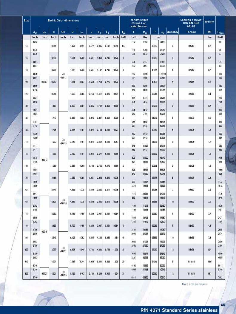
RfN 4071 Standard Series stainless
Size Shrink Disc® dimensions Transmissibletorques oraxial forces
Locking screwsDIN EN ISO
A2-70
Weight
dw Cw d Ch D L1 L d1 L2 I TA T Fax P σv Quantity Thread WT Tmax
Inch Inch Inch Inch Inch Inch Inch Inch Inch Inch lb-ft lb-ft lbs psi n lbs lb-ft
0.394
0.0007
+0 -0.0013
16 1124 61190 2014 0.551 1.457 0.591 0.472 0.945 0.197 0.354 1.5 33350 3 M4x10 0.2 0.472 28 1798 76995 35 0.472 38 2473 62785 4716 0.630 1.614 0.728 0.591 1.063 0.246 0.472 3 36250 3 M5x12 0.2 0.551 59 3147 99180 74 0.551 66 3597 70035 8318 0.709 1.732 0.728 0.591 1.142 0.246 0.472 3 43065 4 M5x12 0.2 0.630 95 4496 119190 119 0.591 87 4496 69455 10920 0.787 1.811 0.807 0.669 1.260 0.276 0.472 3 48430 5 M5x15 0.3 0.669 119 5395 94105 149 0.748 140 5620 63945 17724 0.945 1.969 0.906 0.768 1.417 0.315 0.591 3 38715 6 M5x18 0.4 0.827 184 6744 91785 229 0.945 236 7643 56115 29530 1.181 2.362 0.984 0.846 1.732 0.354 0.669 3 35090 7 M5x18 0.7 1.024 295 8542 74240 369 1.024
+0 -0.0015
243 7194 42775 30236 1.417 2.835 1.083 0.925 2.047 0.394 0.709 6 31030 5 M6x20 0.9 1.181 354 8992 51475 443 1.142
0.0013
361 9442 43645 45038 1.496 2.835 1.181 1.024 2.165 0.433 0.827 6 30160 6 M6x25 1.1 1.220 413 9442 56985 509 1.260 391 9442 50895 48744 1.732 3.150 1.181 1.024 2.402 0.433 0.787 6 31900 7 M6x25 1.2 1.417 546 11465 54375 686 1.417 450 9442 44370 56148 1.890 3.150 1.181 1.024 2.677 0.433 0.866 6 26680 7 M6x25 1.2 1.575 620 11690 48140 774 1.496 671 13488 49590 84150 1.969 3.543 1.260 1.102 2.756 0.472 0.866 6 32915 9 M6x25 1.8 1.654 878 15736 55825 1099 1.654
+0 -0.0018
642 11690 40745 80455 2.165 3.937 1.358 1.201 2.953 0.512 0.906 6 25375 8 M6x25 2.4 1.890 937 14837 49155 1173 1.890 1210 19333 46835 151262 2.441 4.331 1.378 1.220 3.386 0.512 0.906 6 33785 12 M6x30 2.9 2.047 1416 20682 57275 1770 1.969
0.0019
833 12814 44515 104068 2.677 4.528 1.378 1.220 3.386 0.512 0.906 6 25665 10 M6x30 3.1 2.362 1460 11914 59160 1829 2.165 1195 16635 43355 149775 2.953 5.433 1.496 1.280 3.937 0.551 0.984 15 26680 7 M8x30 3.7 2.559 1940 22705 47560 2427 2.362 1364 17310 40600 170480 3.150 5.709 1.496 1.280 3.937 0.551 0.984 15 25085 7 M8x30 4.2 2.756 2124 23154 44950 2655 2.559
+0 -0.0021
2058 24054 39875 257490 3.543 6.102 1.752 1.535 4.488 0.669 1.181 15 26535 10 M8x35 7.3 2.953 3046 31022 41905 3806 2.756 2552 27650 37265 3194
100 3.937 6.693 1.949 1.732 4.882 0.748 1.339 15 25230 12 M8x35 10.4 3.150 3666 34844 37845 4580 2.953 3201 32596 35090 4005
110 4.331 7.283 2.244 1.969 5.354 0.866 1.535 30 24215 9 M10x40 13.0 3.346 4492 40239 35235 5613 3.346
0.0027+0
-0.0025
4595 41138 40745 5746125 4.921 8.465 2.402 2.126 6.299 0.906 1.654 30 26390 12 M10x40 18.3 3.740 6314 50805 40310 7892
More sizes on request
65

RINGFEDER® Smart-Lock
66

Smart-Lock-Set RfN 4001
67

Smart-Lock-Set: the connection of the future
For the perfect hollow shaft connection, the solid shaft is always manufactured to a high degree of precision, normally with a dimensional tolerance of h6/H6. This close tolerance, high-finish shaft is inserted into the equally close tolerance hollow bore of the gearbox and secured in place by the com-pressive force of the Shrink Disc®. Only by maintaining the strict dimensional tolerances the full torque capacity can be reliability achieved. Smart-Lock puts an end to all the precision machining in-volved and guarantees an optimum connection even with clearances up to 0.2 mm (0.008 inches).The flexibility offered by using interchangeable bushings between the solid shaft and the hollow shaft of the gearbox makes the Smart-Lock-Set an invaluable aid to the market-place. Thanks to the availability of shaft adapter bushings with various inside diameters, one gearbox can be used with a range of shaft sizes without a change out of the shaft or Shrink Disc®. The ease of selecting and using the Smart-Lock-Set is child´s play. The Smart-Lock-Set is an efficient design that makes econo-mic sense to the user. Not only can it compensate for larger dimensional tolerances up to 0.2 mm (0.008 inches), it also offers significant cost savings by requiring a minimal number of spare parts needed in inventory. Furthermore, inexpen-sive, cold drawn, commercial available shafting up to quality grade h11 can be utilized without additional machining. The export market also benefits from using Smart-Lock-Set; ad-apter bushings in inch size standards are readily available from local inventories for countries that don´t use metric measurements. Expensive specials and large spare part in-ventories are a thing of the past.
RINGFEDER® Smart-Lock
68

Flexible, cost-saving, easy to maintain: Smart-Lock-Set is the new Shaft/Hollow Shaft connection from RINGFEDER®. Cylindrical Bu-shings allow the attachment of hollow shaft gear reducers and other hollow shaft connections to any metric and inch size solid shaft di-ameter.
• Reliable:Tension-optimized and virtually indestructible Shrink Discs
guarantee the highest possible degree of safety • Uncompromising:
Cylindrical Bushings for a wide range of shaft diameters provide the perfect connection.
• Economical: The Smart-Lock-Set requires minimal labor at installation and reduces spare part inventory costs up to 70 %.
Technical details of the Smart-Lock-Set
For Gearbox manufacturers: • Eight standard sizes of adaptor bushings are available for hollow shaft outside diameters from 44 to 90 mm.
• The inside diameters are variable and accommodate the most common metric and inch size shaft sizes. • Commercially available solid shafting without any machining can be used. Diameters from 25 to 70 mm are possible.
For users of Gearboxes: • The torque to be transmitted is the criterion used to select the shaft diameter. • The optimum shaft size for an individual gearbox can be used in connection with the Smart-Lock-Set. • It is possible to standardize on a certain gearbox size for a range of shaft diameters. The results are lower costs for maintenance and spare parts.
Characteristics
69

RINGFEDER® Smart-Lock RfN 4001
Clamp Bushing
Customer‘s solid shaft
Shrink Disc® Gearbox with hollow shaft (simplified illustration)
Support Bushing
Same hollow shaft - Same Smart-Lock Shrink Disc®
Clamp Bushings fit various shaft diameters
Larger dimensions available upon request. Technical data subject to change without notice. The Smart-Lock-Set is supplied with a RfN 4001 Shrink Disc® only. The bushings are only suitable for one-time use.
Transmissible torque without bushings in presence of d3 and d2 with identical diameter and clearance values as mentioned above, assuming dry contact surfaces.
70

dimensions technical data heat-treated steel
Max. allowable clearance Transmissible
torque tighteningtorqueaxial force screws Weight
Ød 1 Ød 2 Ød 3 Ød 4 Ød 5 Ød 6 ØD L1 L2 L3 L4 T T Fax G TA m
mm/ in. in. in. in. in. in. in. in. in. in. in. lb.-in. lb.-ft. lbs ISO 4014 Ibs-ft lbs1
1.417 1.693 1.949 1.496 3.150 1.614 1.220 1.181 0.709 0.005
5222 435
10566 M6 12 0.7544 1 1/8 5841 487
1.732 1 3/16 6019 5021 1/4 6196 5161 3/16
1.654 1.929 2.343 1.732 3.543 1.772 1.339 1.339 0.709 0.006
7612 634
12814 M6 8.85 2.2050 1 1/4 8054 671
1.969 1 3/8 8851 7381 7/16 9205 7671 3/16
1.890 2.126 2.539 1.969 3.937 1.811 1.378 1.378 0.709 0.006
7966 664
13489 M6 8.85 2.8755 1 1/4 8408 701
2.165 1 3/8 9293 7741 7/16 9647 8041 1/2 10090 8411 3/8
2.047 2.362 2.736 2.126 4.331 1.850 1.417 1.417 0.109 0.006
14869 1239
21806 M6 8.85 3.311 7/16 15622 1302
62 1 1/2 16285 13572.441 1 5/8 17613 1468
1 3/4 18941 15781 5/8
2.362 2.638 2.933 2.441 4.528 1.890 1.457 1.457 0.7090.006
17879 149022031
M6 8.85 3.8668 1 3/4 19295 1608
2.441 1 15/16 21357 17802 0.007 19560 1630 20008
75 1 15/162.559 2.874 3.130 2.638 5.433 1.969 1.535 1.535 0.709
0.006 16374 136416861 M8 22.13 5.95
2.953 2 0.007 16462 13721 15/16
2.756 3.071 3.327 2.835 5.709 1.969 1.535 1.535 0.709
0.006 31155 2596 32148
M8 22.13 6.3980 2
0.00729384 2449
319233.150 2 3/8 34872 29062 7/16 35846 2987
90 2 3/82.953 3.465 3.524 3.031 6.102 2.244 1.811 1.811 0.709 0.007
42041 350335520 M8 22.13 8.603.543 2 7/16 43192 3599
2 3/4 48679 4057
Ø D
Ø d
1h8
Ø d
4
Ø d
6
Ø d
3H7
Ø d
2
Ø d
2
Ø d
3H7
Ø d
6
Ø d
5
L1
L2
L3 L4
Larger dimensions available upon request. Technical data subject to change without notice. The Smart-Lock-Set is supplied with a RfN 4061 Shrink Disc® only. The bushings are only suitable for one-time use.
RfN 4001
Dimensions S.75
71
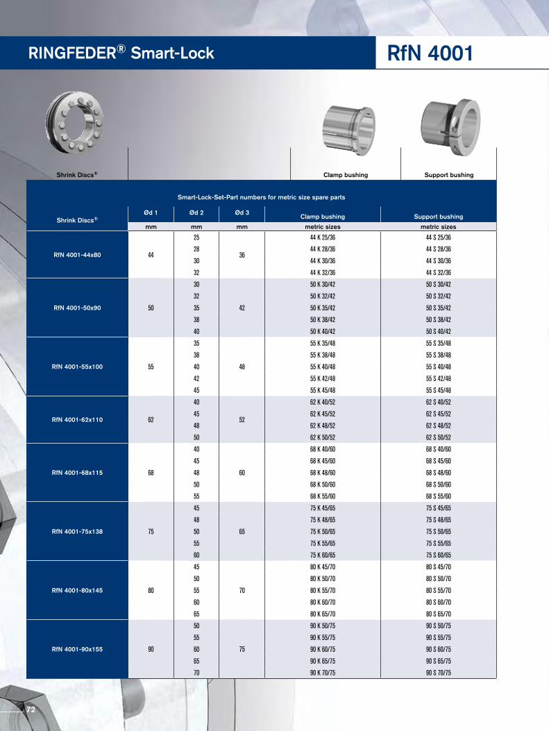
RINGFEDER® Smart-Lock
Smart-Lock-Set-Part numbers for metric size spare parts
Shrink Discs®Ød 1 Ød 2 Ød 3
Clamp bushing Support bushing
mm mm mm metric sizes metric sizes
RfN 4001-44x80 44
25
36
44 K 25/36 44 S 25/36
28 44 K 28/36 44 S 28/36
30 44 K 30/36 44 S 30/36
32 44 K 32/36 44 S 32/36
RfN 4001-50x90 50
30
42
50 K 30/42 50 S 30/42
32 50 K 32/42 50 S 32/42
35 50 K 35/42 50 S 35/42
38 50 K 38/42 50 S 38/42
40 50 K 40/42 50 S 40/42
RfN 4001-55x100 55
35
48
55 K 35/48 55 S 35/48
38 55 K 38/48 55 S 38/48
40 55 K 40/48 55 S 40/48
42 55 K 42/48 55 S 42/48
45 55 K 45/48 55 S 45/48
RfN 4001-62x110 62
40
52
62 K 40/52 62 S 40/52
45 62 K 45/52 62 S 45/52
48 62 K 48/52 62 S 48/52
50 62 K 50/52 62 S 50/52
RfN 4001-68x115 68
40
60
68 K 40/60 68 S 40/60
45 68 K 45/60 68 S 45/60
48 68 K 48/60 68 S 48/60
50 68 K 50/60 68 S 50/60
55 68 K 55/60 68 S 55/60
RfN 4001-75x138 75
45
65
75 K 45/65 75 S 45/65
48 75 K 48/65 75 S 48/65
50 75 K 50/65 75 S 50/65
55 75 K 55/65 75 S 55/65
60 75 K 60/65 75 S 60/65
RfN 4001-80x145 80
45
70
80 K 45/70 80 S 45/70
50 80 K 50/70 80 S 50/70
55 80 K 55/70 80 S 55/70
60 80 K 60/70 80 S 60/70
65 80 K 65/70 80 S 65/70
RfN 4001-90x155 90
50
75
90 K 50/75 90 S 50/75
55 90 K 55/75 90 S 55/75
60 90 K 60/75 90 S 60/75
65 90 K 65/75 90 S 65/75
70 90 K 70/75 90 S 70/75
Shrink Discs® Clamp bushing Support bushing
RfN 4001
72

Smart-Lock-Set-Part numbers for metric size spare parts
Shrink Discs® Ød 1 Ød 2 Ød 3 Clamp bushing Support bushing
mm inch mm inch sizes inch sizes
RfN 4001-44x80 44
1.0
36
44 K 1.0/36 44 S 1.0/36
1.125 44 K 1.125/36 44 S 1.125/36
1.1875 44 K 1.1875/36 44 S 1.1875/36
1.25 44 K 1.25/36 44 S 1.25/36
RfN 4001-50x90 50
1.1875
42
50 K 1.875/42 50 S 1.875/42
1.25 50 K 1.25/42 50 S 1.25/42
1.375 50 K 1.375/42 50 S 1.375/42
1.4375 50 K 1.4375/42 50 S 1.4375/42
RfN 4001-55x100 55
1.1875
48
55 K 1.875/48 55 S 1.875/48
1.25 55 K 1.25/4 55 S 1.875/48
1.375 55 K 1.375/48 55 S 1.875/48
1.4375 55 K 1.4375/48 55 S 1.875/48
1.5 55 K 1.5/48 55 S 1.5/48
RfN 4001-62x110 62
1.375
52
62 K 1.375/52 62 S 1.375/52
1.4375 62 K 1.4375/52 62 S 1.4375/52
1.5 62 K 1.5/52 62 S 1.5/52
1.625 62 K 1.625/52 62 S 1.625/52
1.75 62 K 1.75/52 62 S 1.75/52
1.9375 62 K 1.9375/52 62 S 1.9375/52
RfN 4001-68x115 68
1.625
60
68 K 1.625/60 68 S 1.625/60
1.75 68 K 1.75/60 68 S 1.75/60
1.9375 68 K 1.9375/60 68 S 1.9375/60
2.0 68 K 2.0/60 68 S 2.0/60
RfN 4001-75x138 751.9375
6575 K 1.9375/65 75 S 1.9375/65
2.0 75 K 2.0/65 75 S 2.0/65
RfN 4001-80x145 80
1.9375
70
80 K 1.9375/70 80 S 1.9375/70
2.0 80 K 2.0/70 80 S 2.0/70
2.375 80 K 2.375/70 80 S 2.375/70
2.4375 80 K 2.4375/70 80 S 2.4375/70
RfN 4001-90x155 90
2.375
75
90 K 2.375/75 90 S 2.375/75
2.4375 90 K 2.4375/75 90 S 2.4375/75
2.75 90 K 2.75/75 90 S 2.75/75
Shrink Discs® Clamp bushing Support bushing
73
RINGFEDER® Shaft Couplings
74

WK 5071
WK 5091
75

RINGFEDER rigid sleeve Couplings, type WK 5071 and WK 5091 have a proven track record in the industry. These Couplings are pre-engineered with RINGFEDER Shrink Discs® to connect two components rigidly and backlash free, when there is no misalign-ment between those components permitted. Applications such has conveyor drives, ship drive shafts, line shafts in steel mills, etc., are ideal applications for the standard and heavy duty rigid sleeve Couplings.
Although our catalog shows some preselected standard length sleeve Couplings, our technical staff can custom make a design to fit your needs. We can provide special lengths, materials and versions for every need. Please contact the nearest RINGFEDER POWER TRANSMISSION OFFICE!
Characteristics
RINGFEDER® Shaft Couplings
76

Explanations to tables
d, D, L, l, L1, L2, d1 = Basic dimensions
dW = solid shaft diameter (provided by the customer)
T = transmissible torque
Fax = transmissible axial force
p = approx. surface pressure on the hub extension (diameter d)
TA = required tightening torque per screw (Screws greased with molykote!)
n = quantity of screws
Tmax = maximum theoretical transmissible torque
Cw = shaft clearance
LH = overall Coupling length
LD = overall Shrink Disc® width
σv = calculated combined stress in the hub extension (d/dw) under consideration of the tangential, radial and torsional stresses following the equation:
Additional loads, e.g. tension, thrust or bending have to be taken into consideration accordingly.
Function values The functional characteristics are valid with the screw tighte-ning torque listed in the tables and the following assumed conditions:
The locking screws are lubricated using MoS2 (µtot= 0.1).The tapered cones are lubricated using MoS2 (µ = 0.05). The contact surfaces (dw) are in lightly oiled condition with coefficient of friction µ = 0.12.
The hub and shaft materials have a modulus of elasticity of 30 x 106 PSI. (Lower values result in increased values for T and Fax with reduced tangential stress.)
The maximum clearance is being fully utilized. The shaft being used is solid, for hollow shaft applications the functional values will change.
In cases where the assumed conditions do not apply then contact our Technical Department where we will be happy to assist you with your application.
77

D d dw
LD
LH
RINGFEDER® Shaft Couplings
Explanations
TA = tightening torque per screw (dG)
T = transmissible torque
Fax = transmissible axial force
Further hints, explanations and fundamentals of calcula-tion may be taken from our Shrink Disc® catalog.
Surface
For shaft diameter dw:
peak-to-valley height Ra ≤ 125 RMS.
Clearances considered for the calculati-on of the function values:
dw ISO
above up to clearance Cw INCH INCH INCH
0.236 0.394 0.0005
0.394 0.709 H6/j6 0.0007
0.709 1.181 0.0007
1.181 1.969 H6/h6 0.0013
1.969 3.150 H6/g6 0.0019
3.150 4.724 0.0027
4.724 7.087 0.0031
7.087 9.843 H7/g6 0.0035
9.843 12.402 0.0040
12.402 15.748 0.0044
15.748 19.685 0.0048
WK 5071Standard Duty Coupling
78

Transmissibletorques oraxial forcesSize Coupling dimensions
dw Cw d D LH LD dG TA T Fax
Inch lb-ft lb-ft lbs 0.591
+0 -0.0007
81 427120 0.787 1.811 1.772 0.827 M 5 3 0.669 112 5170 0.748 125 562024 0.945 1.969 1.969 0.906 M 5 3 0.827 184 6519 0.945 221 651930 1.181 2.362 2.165 0.984 M 5 3 1.024 273 7418 1.102 325 1124036 1.417 2.835 2.559 1.102 M 6 9 1.220 465 13038 1.181
+0 -0.0013
446 1393840 1.575 2.953 2.559 1.142 M 6 9 1.260 487 14162 1.260 524 1573644 1.732 3.150 2.756 1.181 M 6 9 1.417 634 17310 1.496 693 1775950 1.969 3.543 3.150 1.260 M 6 9 1.654 1018 20682 1.654 856 1775955 2.165 3.937 3.346 1.378 M 6 9 1.890 1387 21806 1.890 1364 2248062 2.441 4.331 3.543 1.378 M 6 9 2.047 1770 26302 1.969
+0 -0.0019
1475 2180668 2.677 4.528 3.937 1.378 M 6 9 2.362 2323 26976 2.165 1844 2675175 2.953 5.433 4.724 1.496 M 8 22 2.559 2913 34844 2.362 2360 2787580 3.150 5.709 5.118 1.496 M 8 22 2.756 3393 35518 2.559 3503 3821690 3.543 6.102 5.512 1.772 M 8 22 2.953 5347 47208 2.756 5089 43836
100 3.937 6.693 6.299 1.969 M 8 22 3.150 6638 53952 2.953 5310 51479
110 4.331 7.283 7.087 2.244 M 10 44 3.346 7966 58898 3.346
+0 -0.0027
8113 66541125 4.921 8.465 7.874 2.402 M 10 44 3.740 11063 79130 3.740 11137 82502
140 5.512 9.055 8.268 2.717 M 12 74 4.134 14825 95540 4.134 16226 100486
155 6.102 10.433 9.055 2.874 M 12 74 4.528 20652 114423 4.528 22864 133756
165 6.496 11.417 9.449 3.189 M 16 184 4.921 28765 147244 4.921
+0 -0.0031
26552 136004175 6.890 11.811 9.843 3.189 M 16 184 5.315 33190 151740 5.315 38353 174894
185 7.283 12.992 10.433 3.780 M 16 184 5.709 45729 193553 5.512 47941 209738
195 7.677 13.780 11.024 3.780 M 16 184 6.102 60111 240761 5.906 54579 222552
200 7.874 13.780 11.417 3.780 M 16 184 6.299 63430 242784
To continue see next page
WK 507179

WK 5071RINGFEDER® Shaft Couplings
Characteristics
Three part Shrink Disc® heavy duty series – with additional guide mechanism for the inner ring. For the transmission of maxi-mum torques.
Highest reliability – applicable for static, dynamic and impact loads.
Simplified manufacture – only plain shaft and bore diameters with easily achieved surface finishes and tolerances are required.
Fully replaceable – the RINGFEDER® Shrink Discs® work are self releasing.
Visual check of the tightening status – minimization of faults during assembly.
Easy mounting – RINGFEDER® Shrink Discs® use standard screws and tightened using standard tools. No additional machi-ning or fitting work is required.
Short assembly times – cost savings particularly in the case of se- ries production.
Low susceptibility to contamination – when the locking screws are tightened the contact (functional) surfaces are pressed firmly to-gether and prevent contamination by dirt and moisture.
Easy adjustability – No stops, steps, key-ways, splines etc. are required therefore, hubs can be located and locked at any point or angle on the shaft.
Standard Duty Coupling
80

WK 5071
6.299
0.0031
70068 267512220 8.661 14.567 12.205 4.488 M 16 184 6.693 81132 289992 6.693 88507 329107
240 9.449 15.945 13.780 4.803 M 20 361 7.480 115059 376540 7.480
0.0035
120960 395648260 10.236 16.929 15.354 5.236 M 20 361 8.268 151200 451848 8.268 160051 469832
280 11.024 18.110 16.929 5.787 M 20 361 9.055 199141 528280 9.055 202829 546489
300 11.811 19.094 17.520 6.102 M 20 361 9.646 232331 592573 9.449 230119 595046
320 12.598 20.472 18.110 6.142 M 20 361 10.236 275847 651920 9.843
0.0040
287648 701151340 13.386 22.441 18.898 6.772 M 20 361 10.630 339278 764320 10.630 326002 736445
350 13.780 22.835 19.291 6.890 M 20 361 11.220 368780 786800 11.024 341490 744088
360 14.173 23.228 19.685 6.890 M 20 361 11.614 385006 794893 11.417 418197 878968
380 14.961 25.394 20.866 7.205 M 24 620 12.205 485314 954950 11.811 460237 935168
390 15.354 25.984 21.260 7.205 M 24 620 12.598 529568 1008003 12.402
0.0044
494165 957648400 15.748 26.772 21.260 7.205 M 24 620 12.992 548745 1011600 12.992 575297 1090280
420 16.535 27.165 22.835 7.992 M 24 620 13.780 663804 1173456 13.386 594473 1065552
440 17.323 29.528 23.622 8.661 M 24 620 14.173 676343 1144232 14.173 737560 1274616
460 18.110 30.315 24.409 8.661 M 24 620 14.961 840818 1360040 14.961 862945 1382520
480 18.898 31.496 25.394 9.055 M 24 620 15.748 966204 1472440 15.748
0.0048 967679 1474688
500 19.685 33.465 26.378 9.055 M 27 92216.535 1073150 1557864
Transmissibletorques oraxial forcesSize Coupling dimensions
dw Cw d D LH LD dG TA T Fax
Inch Inch Inch Inch Inch Inch Inch lb-ft lb-ft lbs
81

WK 5091RINGFEDER® Shaft Couplings
D d dw
LD
LH
Heavy Duty Coupling
Heavy Duty Coupling
82
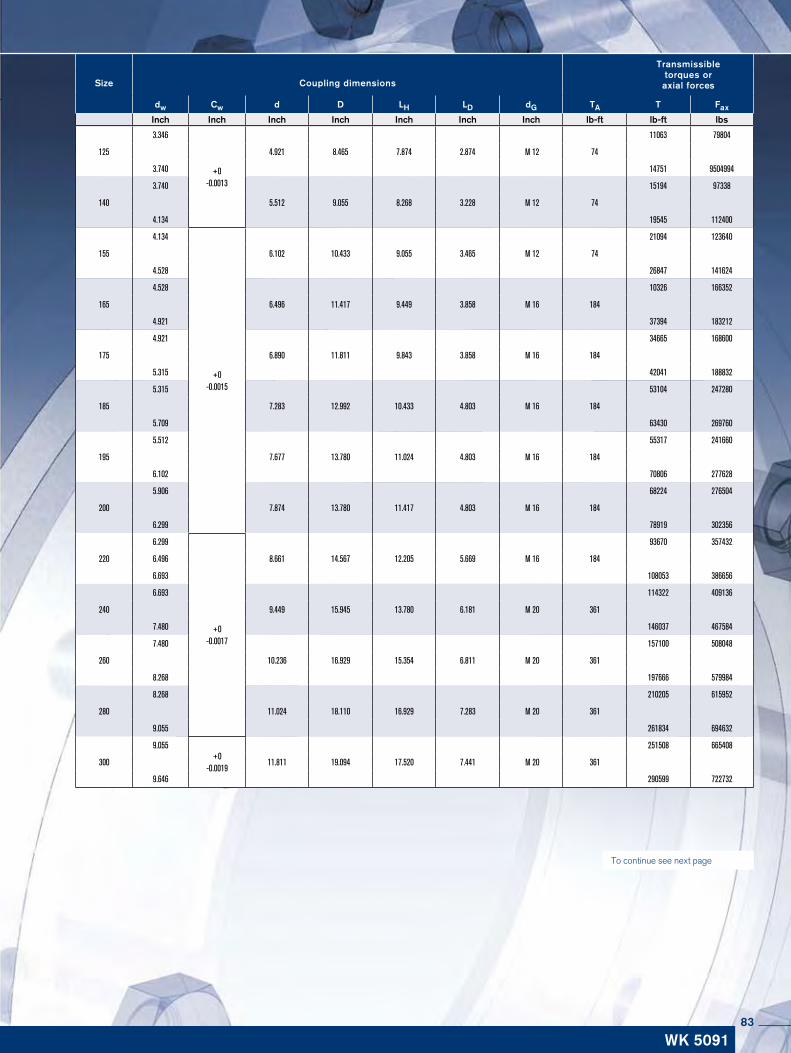
WK 5091
To continue see next page
Transmissibletorques oraxial forcesSize Coupling dimensions
dw Cw d D LH LD dG TA T Fax
Inch Inch Inch Inch Inch Inch Inch lb-ft lb-ft lbs
3.346
+0 -0.0013
11063 79804
125 4.921 8.465 7.874 2.874 M 12 74
3.740 14751 9504994
3.740 15194 97338
140 5.512 9.055 8.268 3.228 M 12 74
4.134 19545 112400
4.134
+0 -0.0015
21094 123640
155 6.102 10.433 9.055 3.465 M 12 74
4.528 26847 141624
4.528 10326 166352
165 6.496 11.417 9.449 3.858 M 16 184
4.921 37394 183212
4.921 34665 168600
175 6.890 11.811 9.843 3.858 M 16 184
5.315 42041 188832
5.315 53104 247280
185 7.283 12.992 10.433 4.803 M 16 184
5.709 63430 269760
5.512 55317 241660
195 7.677 13.780 11.024 4.803 M 16 184
6.102 70806 277628
5.906 68224 276504
200 7.874 13.780 11.417 4.803 M 16 184
6.299 78919 302356
6.299
+0 -0.0017
93670 357432
220 6.496 8.661 14.567 12.205 5.669 M 16 184
6.693 108053 386656
6.693 114322 409136
240 9.449 15.945 13.780 6.181 M 20 361
7.480 146037 467584
7.480 157100 508048
260 10.236 16.929 15.354 6.811 M 20 361
8.268 197666 579984
8.268 210205 615952
280 11.024 18.110 16.929 7.283 M 20 361
9.055 261834 694632
9.055+0
-0.0019
251508 665408
300 11.811 19.094 17.520 7.441 M 20 361
9.646 290599 722732
83
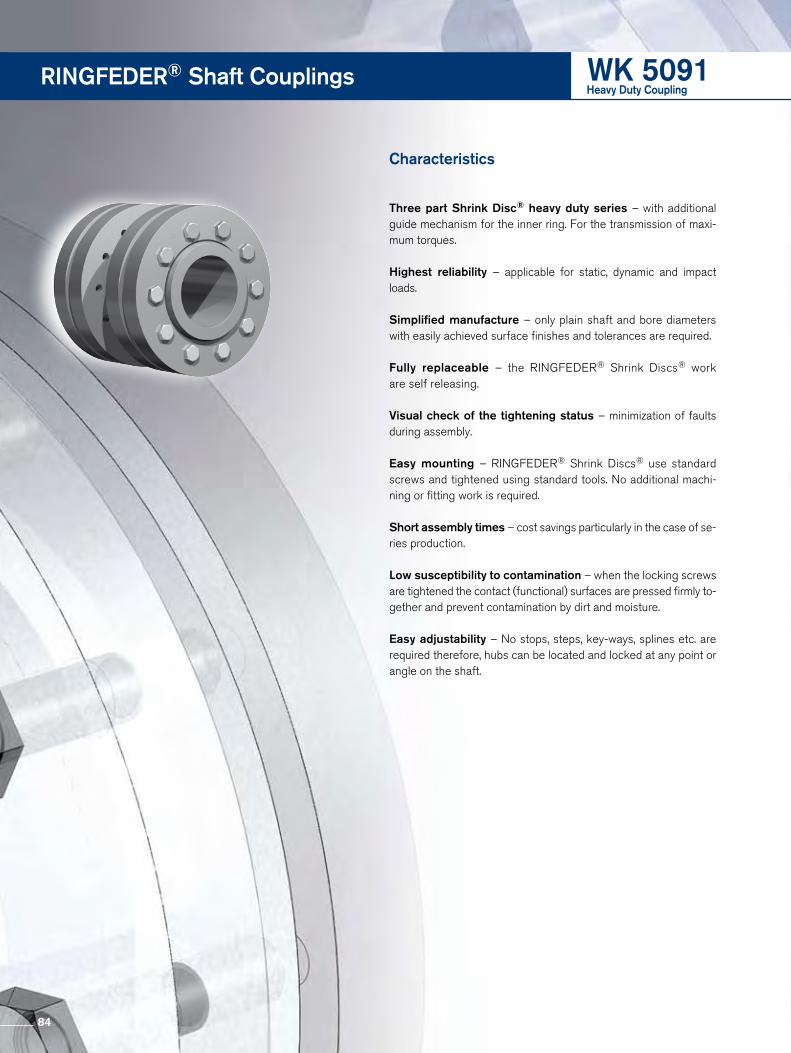
WK 5091RINGFEDER® Shaft Couplings
Characteristics
Three part Shrink Disc® heavy duty series – with additional guide mechanism for the inner ring. For the transmission of maxi-mum torques.
Highest reliability – applicable for static, dynamic and impact loads.
Simplified manufacture – only plain shaft and bore diameters with easily achieved surface finishes and tolerances are required.
Fully replaceable – the RINGFEDER® Shrink Discs® work are self releasing.
Visual check of the tightening status – minimization of faults during assembly.
Easy mounting – RINGFEDER® Shrink Discs® use standard screws and tightened using standard tools. No additional machi-ning or fitting work is required.
Short assembly times – cost savings particularly in the case of se- ries production.
Low susceptibility to contamination – when the locking screws are tightened the contact (functional) surfaces are pressed firmly to-gether and prevent contamination by dirt and moisture.
Easy adjustability – No stops, steps, key-ways, splines etc. are required therefore, hubs can be located and locked at any point or angle on the shaft.
Heavy Duty Coupling
84

WK 5091
Transmissibletorques oraxial forcesSize Coupling dimensions
dw Cw d D LH LD dG TA T Fax
Inch Inch Inch Inch Inch Inch Inch lb-ft lb-ft lbs
9.449
+0 -0.0019
278798 708120
320 12.598 20.472 18.110 7.756 M 20 361
10.236 332640 780056
9.843 361036 878968
340 13.386 22.441 18.898 8.465 M 24 620
10.630 426310 961020
10.630 410083 926626
350 13.780 22.835 19.291 8.465 M 24 620
11.220 463925 992492
11.024 451387 982376
360 14.173 23.228 19.685 8.622 M 24 620
11.614 508179 1049816
11.417
+0 -0.0021
455812 959896
380 14.961 25.394 20.866 8.622 M 24 620
12.205 530306 1044196
11.811 522192 1059932
390 15.354 25.984 21.260 8.937 M 24 620
12.598 600743 1144232
12.402 564233 1091404
400 15.748 26.772 21.260 8.937 M 24 620
12.992 623238 1152100
12.992 736822 1361164
420 16.535 27.165 22.835 9.961 M 24 620
13.780 840818 1464572
13.386 780338 1400504
440 17.323 29.528 23.622 10.591 M 27 922
14.173 888022 1503912
14.173 973579 1672512
460 18.110 30.315 24.409 10.591 M 27 922
14.961 1106340 1787160
14.961
+0 -0.0024
1132155 1816384
480 18.898 31.496 25.394 11.457 M 27 922
15.748 1268603 1933280
15.748 1290730 1967000
500 19.685 33.465 26.378 11.457 M 27 922
16.535 1430866 2079400
85
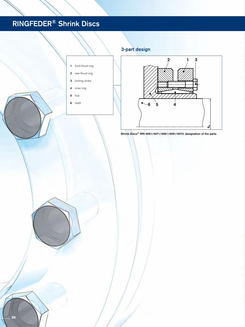
RINGFEDER® Shrink Discs
Shrink Discs® RfN 4051/4071/4061/4091/4073: designation of the parts
1 front thrust ring
2 rear thrust ring
3 locking screw
4 inner ring
5 hub
6 shaft 6
2 1 3
5 4
3-part design
86

Shrink Discs® RfN 4051, 4061, 4071, 4091, 4073
Installation
1. Clean the area on the hub where the Shrink Disc® will be seated and oil to ease assembly, if necessary.
2. Removing spacers which may be present between the thrust rings for transport purposes.
3. Sliding the Shrink Disc® onto the hub. Attention: Do not start tightening the bolts before the shaft
is in the bore of the hub, as this may cause permanent deformation.
4. Slide the hub onto the shaft and position as required. Use a thin oil to lightly lubricate the hub bore and shaft to fa-cilitate assembly.
Attention: Do not use lubricants containing MOS2.
5. Tighten 3 or 4 locking screws that are equally spaced around the diameter to establish a parallel or perpendicu-lar position of Shrink Disc® collar(s) relative to hub web or shaft, respectively. This step properly seats the collar(s) on the taper of the inner ring.
6. Using a torque wrench, tighten all locking screws gradu-ally and in sequence all the way around (not in a diametri-cally opposite sequence). Several passes may be required until all screws are torqued to the specified tightening torque (TA).
7. Verify that the screws are completely tight by applying the specified tightening torque (TA). The gap between the Shrink Disc® collars or between the Shrink Disc® collar and the hub should be even all the way around.
Removal
1. Loosen the bolts evenly and in sequence, again in several circular sequences, to avoid jamming of the discs on the inner ring. Never completely remove the bolts from their threaded holes, this creates a risk of accidents.
2. Slide the Shrink Disc® and its attached part from the shaft. Clean shaft and remove possible traces of rust from the shaft.
Installation and removal instructions
87

RINGFEDER® Shrink Discs
Shrink Discs® RfN 4171/4161/4181: designation of the parts
1 outer ring
2 locking screw
3 inner ring
4 hub
5 shaft
5
1
2
4 3
2-part design
Surfaces aligned!
not assembled
assembled
54 3
2
2
1
88

Shrink Discs® 4161, 4171, 4181
Installation
1. Clean the area on the hub where the Shrink Disc® will be seated and oil to ease assembly, if necessary.
2. Sliding the Shrink Disc® onto the hub. Attention: Do not start tightening before the shaft is in
the bore of the hub; this may cause permanent deforma-tion.
3. Slide the hub onto the shaft and position as required. Use a thin oil to lightly lubricate the hub bore and shaft to fa-cilitate assembly.
Attention: Do not use lubricants containing MOS2.
4. Tighten 3 or 4 locking screws that are equally spaced around the diameter to establish a parallel position of the Shrink Disc® inner relative to outer ring. This step properly seats the the taper of the inner ring.
5. Using a torque wrench, tighten all locking screws gradu-ally and in sequence all the way around (not in a diametri-cally opposite sequence). Several passes may be required until all screws are torqued to the specified tightening torque (TA).
6. Verify that the screws are completely tight by applying the specified tightening torque (TA).
• Assembly, using a torque wrench: Check torquing of the bolts in sequence of their positions. Assembly is only complete once all the bolts have been torqued as specified.
• Assembly, without a torque wrench: Assembly is complete once the faces of the inner and outer rings are aligned flush.
Removal
1. Gradually release the locking bolts all the way around. Begin by releasing each bolt only about one quarter of a turn.
2. If the Shrink Disc® does not loosen, back all screws out until there is a gap between the head of the bolts and the Shrink Disc® face.
3. Completely remove a few screws and thread them into the adjacent removal threads roughly equally spaced around the diameter. Use these fasteners to push the inner ring away from the outer collar until the Shrink Disc® is loose on the shaft.
Installation and removal instructions
89
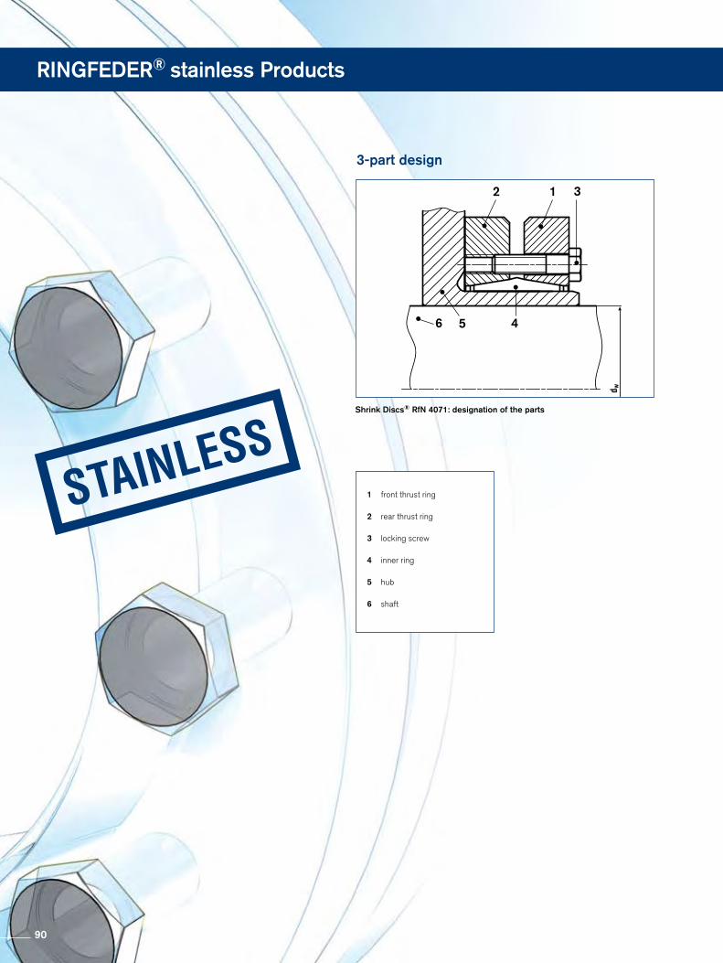
RINGFEDER® stainless Products
Shrink Discs® RfN 4071: designation of the parts
1 front thrust ring
2 rear thrust ring
3 locking screw
4 inner ring
5 hub
6 shaft
6
2 1 3
5 4
3-part design
90

Shrink Discs® RfN 4071 Stainless
Installation
1. Clean the area on the shaft where the Shrink Disc® will be seated and oil lightly to ease assembly, if necessary.
Attention: Do not use lubricants containing MOS2.
2. Fasten the attachment part to the Shrink Disc®. ATTENTION: Tighten the bolts lightly.
3. Slide the Shrink Disc® onto the shaft.
4. Tighten 3 or 4 locking screws that are equally spaced around the diameter to establish a parallel or perpendicu-lar position of Shrink Disc® collar(s) relative to hub web or shaft, respectively. This step properly seats the collar(s) on the taper of the inner ring.
5. Using a torque wrench, tighten all locking screws gradu-ally and in sequence all the way around (not in a diametri-cally opposite sequence). Several passes may be required until all screws are torqued to the specified tightening torque (TA).
6. Verify that the screws are completely tight by applying the specified tightening torque (TA). The gap between the Shrink Disc® collars or between the Shrink Disc® collar and the hub should be even all the way around.
Removal
1. Loosen the bolts evenly and in sequence, again in several circular sequences, to avoid jamming of the discs on the inner ring. Never completely remove the bolts from their threaded holes, this creates a risk of accidents.
2. Slide the Shrink Disc® and its attachment part from the shaft. First remove possible traces of rust from the shaft.
3. Release the attachment part from the Shrink Disc®.
Installation and removal instructions
91

Shafts
ISO Tolerances
Nominal diameter of
shaftd11 e8 e7 f8 f7 g6 h11 h9 h8 h7
INCHabove to upper lower upper lower upper lower upper lower upper lower upper lower upper lower upper lower upper lower upper lower
0.118 0.236 -0.0012 -0.0041 -0.0008 -0.0015 -0.0008 -0.0013 -0.0004 -0.0011 -0.0004 -0.0009 -0.0002 -0.0005 0 -0.0030 0 -0.0012 0 -0.0007 0 -0.0005
0.236 0.394 -0.0016 -0.0051 -0.0010 -0.0019 -0.0010 -0.0016 -0.0005 -0.0014 -0.0005 -0.0011 -0.0002 -0.0006 0 -0.0035 0 -0.0014 0 -0.0009 0 -0.0006
0.394 0.709 -0.0020 -0.0063 -0.0013 -0.0023 -0.0013 -0.0020 -0.0006 -0.0017 -0.0006 -0.0013 -0.0002 -0.0007 0 -0.0043 0 -0.0017 0 -0.0011 0 -0.0007
0.709 1.181 -0.0026 -0.0077 -0.0016 -0.0029 -0.0016 -0.0024 -0.0008 -0.0021 -0.0008 -0.0017 -0.0003 -0.0008 0 -0.0051 0 -0.0020 0 -0.0013 0 -0.0008
1.181 1.969 -0.0031 -0.0094 -0.0020 -0.0035 -0.0020 -0.0030 -0.0010 -0.0025 -0.0010 -0.0020 -0.0004 -0.0010 0 -0.0063 0 -0.0024 0 -0.0015 0 -0.0010
1.969 3.150 -0.0039 -0.0114 -0.0024 -0.0042 -0.0024 -0.0035 -0.0012 -0.0030 -0.0012 -0.0024 -0.0004 -0.0011 0 -0.0075 0 -0.0029 0 -0.0018 0 -0.0012
3.150 4.724 -0.0047 -0.0134 -0.0028 -0.0050 -0.0028 -0.0042 -0.0014 -0.0035 -0.0014 -0.0028 -0.0005 -0.0013 0 -0.0087 0 -0.0034 0 -0.0021 0 -0.0014
4.724 7.087 -0.0057 -0.0156 -0.0033 -0.0058 -0.0033 -0.0049 -0.0017 -0.0042 -0.0017 -0.0033 -0.0006 -0.0015 0 -0.0098 0 -0.0039 0 -0.0025 0 -0.0016
7.087 9.843 -0.0067 -0.0181 -0.0039 -0.0068 -0.0039 -0.0057 -0.0020 -0.0048 -0.0020 -0.0038 -0.0006 -0.0017 0 -0.0114 0 -0.0045 0 -0.0028 0 -0.0018
9.843 12.402 -0.0075 -0.0201 -0.0043 -0.0075 -0.0043 -0.0064 -0.0022 -0.0054 -0.0022 -0.0043 -0.0007 -0.0019 0 -0.0126 0 -0.0051 0 -0.0032 0 -0.0020
12.402 15.748 -0.0083 -0.0224 -0.0049 -0.0084 -0.0049 -0.0072 -0.0024 -0.0059 -0.0024 -0.0047 -0.0007 -0.0021 0 -0.0142 0 -0.0055 0 -0.0035 0 -0.0022
15.748 19.685 -0.0091 -0.0248 -0.0053 -0.0091 -0.0053 -0.0078 -0.0027 -0.0065 -0.0027 -0.0052 -0.0008 -0.0024 0 -0.0173 0 -0.0061 0 -0.0038 0 -0.0025
Nominal diameter of
shafth6 h5 j6 k6 k5 m6 m5 n6 p6
INCHabove to upper lower upper lower upper lower upper lower upper lower upper lower upper lower upper lower upper lower
0.118 0.236 0 -0.0003 0 -0.0002 +0.0003 0.0000 - – – +0.0005 +0.0002 +0.0004 +0.0002 +0.0006 +0.0003 +0.0008 +0.0005
0.236 0.394 0 -0.0004 0 -0.0002 +0.0003 -0.0001 +0.0004 +0.0000 +0.0003 +0.0000 +0.0006 +0.0002 +0.0005 +0.0002 +0.0007 +0.0004 +0.0009 +0.0006
0.394 0.709 0 -0.0004 0 -0.0003 +0.0003 -0.0001 +0.0005 +0.0000 +0.0004 +0.0000 +0.0007 +0.0003 +0.0006 +0.0003 +0.0009 +0.0005 +0.0011 +0.0007
0.709 1.181 0 -0.0005 0 -0.0004 +0.0004 -0.0002 +0.0006 +0.0001 +0.0004 +0.0001 +0.0008 +0.0003 +0.0007 +0.0003 +0.0011 +0.0006 +0.0014 +0.0010
1.181 1.969 0 -0.0006 0 -0.0004 +0.0004 -0.0002 +0.0007 +0.0001 +0.0005 +0.0001 +0.0010 +0.0004 +0.0008 +0.0004 +0.0013 +0.0007 +0.0017 +0.0010
1.969 3.150 0 -0.0007 0 -0.0005 +0.0005 -0.0003 +0.0008 +0.0001 +0.0006 +0.0001 +0.0012 +0.0004 +0.0009 +0.0004 +0.0015 +0.0008 +0.0020 +0.0013
3.150 4.724 0 -0.0009 0 -0.0006 +0.0005 -0.0004 +0.0010 +0.0001 +0.0007 +0.0001 +0.0014 +0.0005 +0.0011 +0.0005 +0.0018 +0.0009 +0.0023 +0.0015
4.724 7.087 0 -0.0010 0 -0.0007 +0.0006 -0.0004 +0.0011 +0.0001 +0.0008 +0.0001 +0.0016 +0.0006 +0.0013 +0.0006 +0.0020 +0.0011 +0.0027 +0.0017
7.087 9.843 0 -0.0011 0 -0.0008 +0.0006 -0.0005 +0.0013 +0.0002 +0.0009 +0.0002 +0.0018 +0.0007 +0.0015 +0.0007 +0.0024 +0.0012 +0.0031 +0.0020
9.843 12.402 0 -0.0013 0 -0.0009 +0.0006 -0.0006 +0.0014 +0.0002 +0.0011 +0.0002 +0.0021 +0.0008 +0.0017 +0.0008 +0.0026 +0.0013 +0.0035 +0.0022
12.402 15.748 0 -0.0014 0 -0.0010 +0.0007 -0.0007 +0.0016 +0.0002 +0.0011 +0.0002 +0.0022 +0.0008 +0.0018 +0.0008 +0.0029 +0.0015 +0.0039 +0.0024
15.748 19.685 0 -0.0016 0 -0.0011 +0.0008 -0.0008 +0.0018 +0.0002 +0.0013 +0.0002 +0.0025 +0.0009 +0.0020 +0.0009 +0.0031 +0.0016 +0.0043 +0.0027
92

mm
Bores
Nominal diameter of
bored11 e8 e7 f8 f7 g6 h11 h9 h8 h7
INCHabove to upper lower upper lower upper lower upper lower upper lower upper lower upper lower upper lower upper lower upper lower
0.118 0.236 +0.0041 +0.0012 +0.0015 +0.0008 +0.0013 +0.0008 +0.0011 +0.0004 +0.0009 +0.0004 +0.0006 +0.0002 +0.0030 0 +0.0012 0 +0.0007 0 +0.0005 0
0.236 0.394 +0.0051 +0.0016 +0.0019 +0.0010 +0.0016 +0.0010 +0.0014 +0.0004 +0.0011 +0.0005 +0.0008 +0.0002 +0.0035 0 +0.0014 0 +0.0009 0 +0.0006 0
0.394 0.709 +0.0063 +0.0020 +0.0023 +0.0013 +0.0020 +0.0013 +0.0017 +0.0005 +0.0013 +0.0006 +0.0009 +0.0002 +0.0043 0 +0.0017 0 +0.0011 0 +0.0007 0
0.709 1.181 +0.0077 +0.0026 +0.0029 +0.0016 +0.0024 +0.0016 +0.0021 +0.0006 +0.0016 +0.0008 +0.0011 +0.0003 +0.0051 0 +0.0020 0 +0.0013 0 +0.0008 0
1.181 1.969 +0.0094 +0.0031 +0.0035 +0.0020 +0.0030 +0.0020 +0.0025 +0.0007 +0.0020 +0.0010 +0.0013 +0.0004 +0.0063 0 +0.0024 0 +0.0015 0 +0.0010 0
1.969 3.150 +0.0114 +0.0039 +0.0042 +0.0024 +0.0035 +0.0024 +0.0030 +0.0008 +0.0024 +0.0012 +0.0016 +0.0004 +0.0075 0 +0.0029 0 +0.0018 0 +0.0012 0
3.150 4.724 +0.0134 +0.0047 +0.0050 +0.0028 +0.0042 +0.0028 +0.0035 +0.0010 +0.0028 +0.0014 +0.0019 +0.0005 +0.0087 0 +0.0034 0 +0.0021 0 +0.0014 0
4.724 7.087 +0.0156 +0.0057 +0.0058 +0.0033 +0.0049 +0.0033 +0.0042 +0.0011 +0.0033 +0.0017 +0.0021 +0.0006 +0.0098 0 +0.0039 0 +0.0025 0 +0.0016 0
7.087 9.843 +0.0181 +0.0067 +0.0068 +0.0039 +0.0057 +0.0039 +0.0048 +0.0013 +0.0038 +0.0020 +0.0024 +0.0006 +0.0114 0 +0.0045 0 +0.0028 0 +0.0018 0
9.843 12.402 +0.0201 +0.0075 +0.0075 +0.0043 +0.0064 +0.0043 +0.0054 +0.0014 +0.0043 +0.0022 +0.0027 +0.0007 +0.0126 0 +0.0051 0 +0.0032 0 +0.0020 0
12.402 15.748 +0.0224 +0.0083 +0.0084 +0.0049 +0.0072 +0.0049 +0.0059 +0.0016 +0.0047 +0.0024 +0.0030 +0.0007 +0.0142 0 +0.0055 0 +0.0035 0 +0.0022 0
15.748 19.685 +0.0248 +0.0091 +0.0091 +0.0053 +0.0078 +0.0053 +0.0065 +0.0018 +0.0052 +0.0027 +0.0033 +0.0008 +0.0157 0 +0.0061 0 +0.0038 0 +0.0025 0
Nominal diameter of
shafth6 J7 J6 K7 K6 M7 M6 N7 N6 P7
INCHabove to upper lower upper lower upper lower upper lower upper lower upper lower upper lower upper lower upper lower upper lower
0.118 0.236 +0.0003 0 +0.0002 -0.0003 +0.0002 -0.0002 - - - - 0 -0.0005 0.0000 -0.0004 -0.0002 -0.0006 -0.0002 -0.0005 -0.0003 -0.0008
0.236 0.394 +0.0004 0 +0.0003 +0.0003 +0.0002 -0.0002 2E-04 -0.0004 0.0001 -0.0003 0 -0.0006 -0.0001 -0.0005 -0.0002 -0.0007 -0.0003 -0.0006 -0.0004 -0.0009
0.394 0.709 +0.0004 0 +0.0004 -0.0003 +0.0002 -0.0002 2E-04 -0.0005 0.0001 -0.0004 0 -0.0007 -0.0002 -0.0006 -0.0002 -0.0009 -0.0004 -0.0008 -0.0004 -0.0011
0.709 1.181 +0.0005 0 +0.0005 -0.0004 +0.0003 -0.0002 2E-04 -0.0006 0.0001 -0.0004 0 -0.0008 -0.0002 -0.0007 -0.0003 -0.0011 -0.0004 -0.0009 -0.0006 -0.0014
1.181 1.969 +0.0006 0 +0.0006 -0.0004 +0.0004 -0.0002 3E-04 -0.0007 0.0001 -0.0005 0 -0.0010 -0.0002 -0.0008 -0.0003 -0.0013 -0.0005 -0.0011 -0.0007 -0.0017
1.969 3.150 +0.0007 0 +0.0007 -0.0005 +0.0005 -0.0002 4E-04 -0.0008 0.0002 -0.0006 0 -0.0012 -0.0002 -0.0009 -0.0004 -0.0015 -0.0006 -0.0013 -0.0008 -0.0020
3.150 4.724 +0.0009 0 +0.0009 -0.0005 +0.0006 -0.0002 4E-04 -0.0010 0.0002 -0.0007 0 -0.0014 -0.0002 -0.0011 -0.0004 -0.0018 -0.0006 -0.0015 -0.0009 -0.0023
4.724 7.087 +0.0010 0 +0.001 -0.0006 +0.0007 -0.0003 5E-04 -0.0011 0.0002 -0.0008 0 -0.0016 -0.0003 -0.0013 -0.0005 -0.0020 -0.0008 -0.0018 -0.0011 -0.0027
7.087 9.843 +0.0011 0 +0.0012 -0.0006 +0.0009 -0.0003 5E-04 -0.0013 0.0002 -0.0009 0 -0.0018 -0.0003 -0.0015 -0.0006 -0.0024 -0.0009 -0.0020 -0.0013 -0.0031
9.843 12.402 +0.0013 0 +0.0014 -0.0006 +0.001 -0.0003 6E-04 -0.0014 0.0002 -0.0011 0 -0.0020 -0.0004 -0.0016 -0.0006 -0.0026 -0.0010 -0.0022 -0.0014 -0.0035
12.402 15.748 +0.0014 0 +0.0015 -0.0007 +0.0011 -0.0003 7E-04 -0.0016 0.0003 -0.0011 0 -0.0022 -0.0004 -0.0018 -0.0006 -0.0029 -0.0010 -0.0024 -0.0016 -0.0039
15.748 19.685 +0.0016 0 +0.0017 -0.0008 +0.0013 -0.0003 7E-04 -0.0018 0.0003 -0.0013 0 -0.0025 -0.0004 -0.0020 -0.0007 -0.0031 -0.0011 -0.0026 -0.0018 -0.0043
93

To make it easier for our technical staff and to avoid errors or mistakes your inquiry should include the following information:
Information for technical service
Expected maximum loads:
Max. torque T max. = lb-ftMax. bending moment M max. = lb-ftMax. axial load F max. = lbsMax. radial load Fr max. = lbs
Dimensions, materials:
Shaft diameter dw = inchesIn case of hollow shaft, internal diameter dB = inchesSpeed n = rpmHub outside diameter DN = lbsHub width B = inchesHub material yield strength Rp0.2N = psiShaft material yield strength Rp0.2W = psiAmbient temperature Temp. = degree F
Additional information:
Please send a drawing or sketch together with your inquiry!
To get a design proposal for RINGFEDER® shaft-hub-connections
MARYLAND METRICS P.O. Box 261 Owings Mills, MD 21117 USA
Faxes: (410)358-3142 (800)872-9329
From
Company
attn. Dept.
Address
Phone Fax
Please have someone contact me at the following number or email address:
Fax Inquiry
94

Delivery ProgrammeDelivery Program
Locking Devices
Locking Assemblies Locking Elements Shrink Discs®
Damping Technology
Friction Springs DEFORM plus®
DEFORM plus® RFluid Elastomeric Damper
Special Solutions
Magnetic Couplings Servo-Insert Couplings
Safety CouplingsRING-flex® – torsionallyrigid Disc Couplings
Locking Assemblies Flange Couplings
Line Shafts
Smart-Lock
Shaft Couplings
Metal Bellows CouplingsCouplings
95

RINGFEDER POWER TRANSMISSION
RINGFEDER POWER TRANSMISSION GMBHWerner-Heisenberg-Straße 18, D-64823 Groß-Umstadt, Germany · Phone: +49 (0) 6078 9385-0 · Fax: +49 (0) 6078 9385-100
RINGFEDER Products are available from MARYLAND METRICSP.O. Box 261 Owings Mills, MD 21117 USA phones: (410)358-3130 (800)638-1830 faxes: (410)358-3142 (800)872-9329
email: [email protected] web: http://mdmetric.com RFQ form: http://mdmetric.com/rfq.htm