Embed Size (px)
Citation preview
Technology working for you.
EcoPower 55 – 300 t
Simply the Best.

�
Special features of the EcoPower series 55 – 300 t
The all-electric EcoPower, with clamping forces ranging from 55 to 300 t, combines efficiency with precision. The beltless EcoPower scores with a com-pact injection unit and the clean design of its clamping unit, together with a highly efficient direct drive. The machine also offers a small footprint and is open at the top and on the injection side.
Barrel change from above
The barrel can be completely removed from above. It can also be held in an intermediate position, from which the screw can be quickly removed to the rear for easy maintenance. The use of existing barrels from the HM and TM series is also possible.
Integrated peripheral equipment from Wittmann
Peripheral equipment from Wittmann built into the machine frame helps to substantially reduce the machine s space requirements. The entire peripheral equipment can also be operated, visualized and its data stored directly via the machine s Unilog B6 control system.
Fast, precise injection
The injection unit is laid out for high-speed and high-precision injection processes even under maximum injection pressure. The encapsulated drive is clean and compact. Injection and metering are effected via a dual drive with a circulating ball spindle at its center.The EcoPower comes with air cooling as standard and twoextension options: water cooling with either an open or a closed cooling circuit.
The promise: energy-saving, clean and compact
EcoP
ower
(Eng
lisch
) BP-
0000
0066
| �
009/
10 R
C
Sub
ject
to c
hang
e.
3
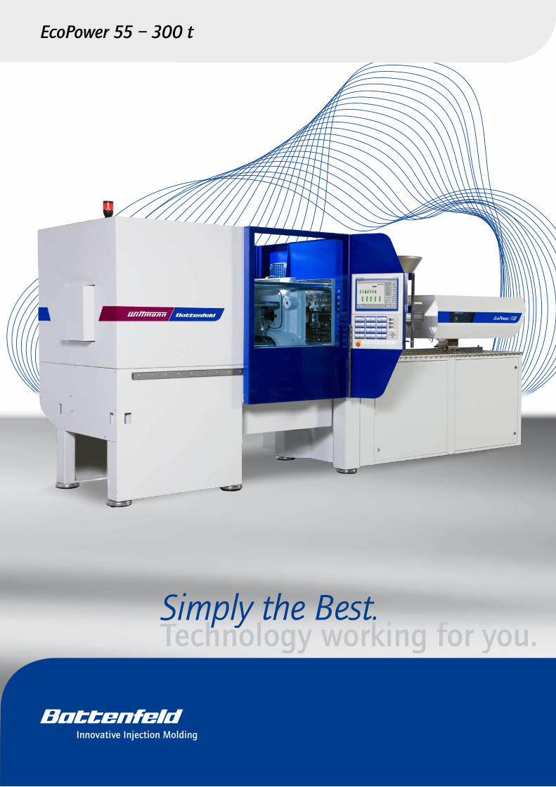
Efficient direct drive
The precise, efficient direct toggle drive stands out by its high dynamics and positioning accuracy. It is alsoextremely energy-efficient.
Toggle system
The toggle encasements are sealed on the outside to ensure a clean clamping unit suitable for clean room applications as standard. Starting the injection process parallel to clamping force build-up is also possible in the standard version, leading to a gain in cycle time.
Drive for peripheral movements
A speed-controlled servo-hydraulic drive is used in the standard version, which features a hydraulic ejector, a hydraulic nozzle stroke and an optional core pull. All-electric drives for these functions are available as an option.
Linear guides
The moving platen is supported by smooth-running linear guides. The hard chrome plated tie-bars are released, which prevents the formation of lubricant deposits in the mold space. The smoothness of the linear guides favors optimal mold protection.
Flexible safety gate and operating panel
The safety gate, open at the top, is flexible enough to accommodate automation equipment, and easy to clean. The swivel-mounted touch screen of the machine s control system is positioned ergonomically and can be moved to the most convenient working position, which also allows easy access to the nozzle area.

�
EcoPower – Experience meets Innovation
Configuration Cooling Hydraulic aggregate Electrical equipment Injection speed
Standard • Air Water Ejector Nozzlestroke Core pull Ejector Nozzle
stroke Standard High-speed
Basis standard • • • •
Basis all-electric • • • •
Packages Basis
- Clean-room package all-electric • • • •
- High-speed standard • • • •
- LIM standard • • • •
- freely configurable standard • • • • •
Precision and speedAccurate and powerful
Highest standard of repeatability in the injection process
Increased injection and metering performance as an option for high-speed models
Parallel movements of all axes
CleanlinessBeltless direct drives in the clamping and injection units
Clean, lubricant-free mold space thanks to linear guides and sealed toggle encasements
Perfect suitability for clean room and medical applications
•
•
•
•
•
•
•
Energy-efficiencyMinimal energy consumption with internal use of braking energy for power supply to the control system and for barrel heating (patent pending)
Small footprint and extremely low noise emission (<68 dba)
Highest degrees of efficiency with latest servo drive technology
CompactnessCompact design with generous ejection space open at the bottom
Integration of Wittmann peripheral equipment, such as robots, dryers and temperature controllers, into the UNILOG B6 control system
Reduction in footprint by integration of dryers and temperatur controllers in the machine frame
Integration of the servo hydraulic aggregate for peripheral movements in the machine frame
•
•
•
•
•
•
•
The production of all-electric injection molding machines has a long tradition at Battenfeld. With the new EcoPower machine series, Wittmann Battenfeld demonstrates its more than �0 years of expertise in the construction of all-electric injection molding machines. This fourth genera-tion is now setting new benchmarks in user-friendliness and precision. It also offers enormous energy-saving potential.
The EcoPower offers you the ultimate in modularity and can be laid out perfectly to suit the area of application. This helps to avoid unnecessary costs for unused equipment on the one hand, and on the other hand there are no more restrictions to optimal utilization of the machine. Here, all-electric systems offer the most generous scope.
The EcoPower „customizing system“ will help you to select the right machine model. Beginning with the standard high-precision equipment and ranging from clean room to high-speed applications, everything can be simply put together according to a customer‘s specific need. Normal equipment options for the injection side, the clamping side, the electrical system, the control system, media and automation can all be selected from a catalogue.
This is how you will benefit from the new Wittmann Battenfeld EcoPower:
Modularity/flexibilityNumerous configuration possibilities and optional extras for maximum customer benefit
All familiar process technology modules are available as usual
Equipment to customer s specifications ranging from standard high-precision injection molding and clean room technology to packaging and thin-wall applications
Air cooling as standard or optional water cooling with open or closed cooling circuit
Ideal for automation – from space-saving insider solutions to sophisticated automation concepts
•
•
•
•
•
5
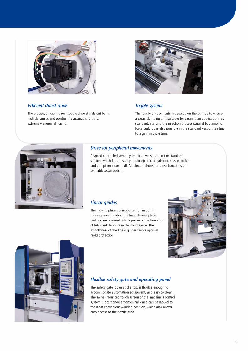
The control system generation UNILOG B6
UNILOG B6 is the proven generation of control systems setting bench-marks in user-friendliness, speed and precision. Continuity in theBATTENFELD operation philosophy and symbolism has been achieved by retention of components from the predecessor generation – with the addition of an extended graphical user interface.
A high-performance system concept optimally adapted to the require-ments of the machine’s drivers and sensors ensures fast,accurate movements of all machine axes. Precise analysis of all impor-tant process parameters provides users with the necessary control for complex applications.
The entire machine documentation including all manuals, spare part drawings and parts lists can also be retrieved. Users can also enter their own PDF files and place them at the disposal of operating staff. A number of additional functions have become available as standard in this version, such as an extended quality table with trend and SPC
analysis, an extended alarm system and more detailed logbook re-cording, several envelope curves for monitoring, additional user page functions and cycle time analysis. Operation of the machine axes is carried out via additional membrane keys.
15" TFT color screen with unrestricted touch-screen function for operation and display.
� rows of soft keys to operate machine functions.
�8 membrane keys to operate the machine axes and optional equipment (optional).
Space for 7 additional optional switches/buttons.
10 membrane keys with illuminated rings are available to operate the main functions of the machine such as drive, heaters, operational modes (optional).
The operating terminal is equipped with � USB interfaces for connecting data storage media (such as a USB stick, printer, or keyboard) or for use as an access control system with a password. More interfaces, i.e. � USB and � Ethernet interfaces, are located in the control cabinet at the rear.
Easiest integration into IT-systems due to Windows XP ™ operating system.
Energy consumption monitoring for motors and heating.

6
Clamping Unit Injection Unit
to 130 350 750 1330*
55 •
110 • •
180 • •
��0 * • •
300 * • •
Factor
Material
ABS 0,88
CA 1,0�
CAB 0,97
PA 0,91
PC 0,97
PE 0,71
PMMA 0,9�
POM 1,15
PP 0,73
The maximum shotweights (g) are calculated by multiplying thetheoretical shot volume (cm3) by the above factor.
Factor
Material
PP + �0% Talc 0,85
PP + �0% Talc 0,98
PP + �0% GF 0,85
PS 0,91
PVC-hard 1,1�
PVC-soft 1,0�
SAN 0,88
SB 0,88
PF 1,3
UP 1,6
Dark grey boxes = Thermosets
Possible combinations of clamping units/injection units
Shot weight conversion table
* available from HY �010
7
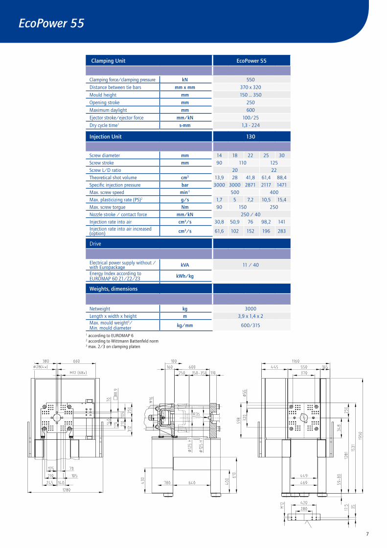
Clamping Unit EcoPower 55
Clamping force/clamping pressure kN 550
Distance between tie bars mm x mm 370 x 3�0
Mould height mm 150 ... 350
Opening stroke mm �50
Maximum daylight mm 600
Ejector stroke/ejector force mm/kN 100/�5
Dry cycle time1 s-mm 1,3 - ���
Injection Unit 130
Screw diameter mm 1� 18 �� �5 30
Screw stroke mm 90 110 1�5
Screw L/D ratio �0 ��
Theoretical shot volume cm3 13,9 �8 �1,8 61,� 88,�
Specific injection pressure bar 3000 3000 �871 �117 1�71
Max. screw speed min-1 500 �00
Max. plasticizing rate (PS)� g/s 1,7 5 7,� 10,5 15,�
Max. screw torgue Nm 90 150 �50
Nozzle stroke / contact force mm/kN �50 / �0
Injection rate into air cm3/s 30,8 50,9 76 98,� 1�1Injection rate into air increased (option) cm3/s 61,6 10� 15� 196 �83
Drive
Electrical power supply without / with Europackage kVA 11 / �0
Energy Index according toEUROMAP 60 Z1/Z�/Z3 kWh/kg
Weights, dimensions
Netweight kg 3000
Length x width x height m 3,9 x 1,� x �Max. mould weight3/Min. mould diameter kg/mm 600/315
1 according to EUROMAP 6� according to Wittmann Battenfeld norm3 max. �/3 on clamping platen
EcoPower 55

8
Clamping Unit EcoPower 110
Clamping force/clamping pressure kN 1100
Distance between tie bars mm x mm �70 x ��0
Mould height mm �00 ... �50
Opening stroke mm 380
Max. daylight mm 830
Ejector stroke/ejector force mm/kN 1�0/�5
Dry cycle time1 s-mm 1,5 - �9�
Injection Unit 130 350
Screw diameter mm 1� 18 �� �5 30 �5 30 35 �0
Screw stroke mm 90 110 1�5 175
Screw L/D ratio �0 �� ��
Theoretical shot volume cm3 13,9 �8 �1,8 61,� 88,� 85,9 1�� 168 ��0
Specific injection pressure bar 3000 3000 �871 �117 1�71 3000 �8�3 �083 1591
Max. screw speed min-1 500 �00 350
Max. plasticizing rate (PS)� g/s 1,7 5 7,� 10,5 15,� 9,3 13,5 �1 33,5
screw torgue Nm 90 150 �50 500
Nozzle stroke/contact force mm/kN �50 / �0 �50 / �0
Injection rate into air cm3/s 30,8 50,9 76 98,� 1�1 98,� 1�1 19� �51Injection rate into air increased (option) cm3/s 61,6 10� 15� 196 �83 196 �83 385 503
Drive
Electrical power supply without/with Europackage kVA 17 / �6 �8 / 58
Energy Index according toEUROMAP 60 Z1/Z�/Z3 kWh/kg
Weights, dimensions
Netweight kg �600 �800
Length x width x height m �,� x 1,5 x �,1 �,� x 1,5 x �,1Max. mould weight3/Min. mould diameter kg/mm 1000 / �00 1000 / �00
1 according to EUROMAP 6� according to Wittmann Battenfeld norm3 max. �/3 on clamping platen
EcoPower 110
9
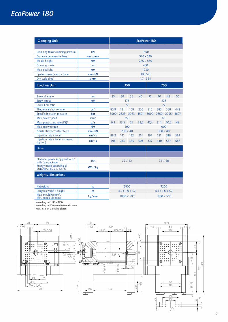
Clamping Unit EcoPower 180
Clamping force/clamping pressure kN 1800
Distance between tie bars mm x mm 570 x 5�0
Mould height mm ��5 ... 550
Opening stroke mm �80
Max. daylight mm 1030
Ejector stroke/ejector force mm/kN 180/�0
Dry cycle time1 s-mm 1,7 - 36�
Injection Unit 350 750
Screw diameter mm �5 30 35 �0 35 �0 �5 50
Screw stroke mm 175 ��5
Screw L/D ratio �� ��
Theoretical shot volume cm3 85,9 1�� 168 ��0 �16 �83 358 ���
Specific injection pressure bar 3000 �8�3 �083 1591 3000 �650 �095 1697
Max. screw speed min-1 350 3�5
Max. plasticizing rate (PS)� g/s 9,3 13,5 �1 33,5 �7,� 31,1 �0,5 �9
Max. screw torgue Nm 500 900
Nozzle stroke/contact force mm/kN �50 / �0 350 / �0
Injection rate into air cm3/s 98,� 1�1 19� �51 19� �51 318 393Injection rate into air increased (option) cm3/s 196 �83 385 503 337 ��0 557 687
Drive
Electrical power supply without/with Europackage kVA 3� / 6� 38 / 68
Energy Index according toEUROMAP 60 Z1/Z�/Z3 kWh/kg
Weights, dimensions
Netweight kg 6800 7�00
Length x width x height m 5,� x 1,6 x �,� 5,5 x 1,6 x �,�Max. mould weight3/Min. mould diameter kg/mm 1800 / 500 1800 / 500
1 according to EUROMAP 6� according to Wittmann Battenfeld norm3 max. �/3 on clamping platen
EcoPower 180

10
Cooling and ConditioningCooling-water flow controller with temperature gauges in return lines, �-way, 3 free available circuits
Electrical componentsOperating voltage �30/�00 V-3PH, 50 Hz
Common voltage supply for drive and heat
Separate voltage supply for drive and heat USA/CDN
Control Unit UNILOG B6 with touchscreen, operating system Windows XP
Software for operating hours counter
Closing/Opening - 5 profile steps
Ejection forward/back - 3 profile steps
Nozzle forward/back - 3 profile steps
Injection/Holding pressure - 10 profile steps
Injection parallel to clamp force build-up
Screw speed/Back pressure - 6 profile steps
Parts counter with good/bad part evaluation
Purging program
Stroke zero offset settings
Start-up program
Adjustable injection pressure limitation
Switchover to holding pressure MASTER/SLAVE by injection time, screw stroke/injection volume and injection pressure
Self-teaching temperature controller
Display of temperature inside electrical cabinet
Seven-day timer
Access authorization via USB interface
Access protection via password system
Freely configurable status bar
Physical, process-related units
15“ TFT colour screen - Touch screen
Energy consumption monitoring for motors and heating, cyclic recording
Automatic dimming
Logbook with filter function
User programming system „APS“Cycle time analysis� freely configurable network connections
Freely configurable screen pages „User page“
Notepad function
Hardcopy function
Internal data storage via USB connection or network
Online language selection
Online selection of imerial or metric units
Operator manual incl. hydr., mech. and el. schedules online
Time Monitoring
Quality table, 10.000 storage depth
Trend diagram
SPC charts
Events protocol (logbook) for 10.000 events
Actual value graphics with 16 curves
� Envelope curves monitorings
Injection Integral supervision
Metering Integral supervision
Alarm message via E-MAIL
USB - �x operating unit
1 Ethernet interface
Printer via USB connection or network
Standard features EcoPower – UNILOG B6
Machine in generalPaint RAL 70�7 tele grey/RAL 500� ultramarine blue
One-piece machine frame
Built-in control cabinet
Parts transport on operator side, rear side or axial
Automatic central lubrication system
Clamping unitClamping system with 5-point twin toggle, servo electrical direct drive via ball screwServo-electric mold height adjustment
Adjustable clamping and opening stroke, adjustable mold locking system
Mould safety program with envelope curves monitoring for optimal mould cover
Precise platen parallelism with low-maintenance moving platen support
Platen drillings and register rings as per EUROMAP
Fixing holes for robot on top of the fixed platen as per EUROMAP 18
Clamping force display on screen
Clamping force monitoring incl. Display via screen
Base MachineIntegrated servohydraulic power unit containing speed controlled servomotor and internal gear pump for ejector and nozzle movement includingadjustable nozzle contact force
Base Machine fully electricServoelectric ejector and injection unit movement
Injection UnitServo closed loop control
Screw drive by 3-phase servo motor, screw speed continuously adjustable via screen
Screw with check valve, screw and barrel nitrated
Thermocouple failure monitor
Plug-in ceramic heater bands
Open nozzle
Quick cylinder removal to the top
Barrel guarding
Hopper of V�A stainless steel can be shut and emptied
Linear bearings for the injection unit
Selectable barrel stand-by temperature
Decompression before and/or after metering
Physical units - bar, ccm, mm/s etc.
Screw protection
Peripheral screw speed indication
Linear interpolation of holding pressure set values
Bar chart for barrel temperature with set value and actual value display
Selectable injection pressure limitationChangeover from injection to holding pressure depending on stroke, time and pressure
Safety gateMaintenance-free safety gate locked by electromagnet
Safety gate free for mould change and handling by robot
Monitored safety gate according CE
11
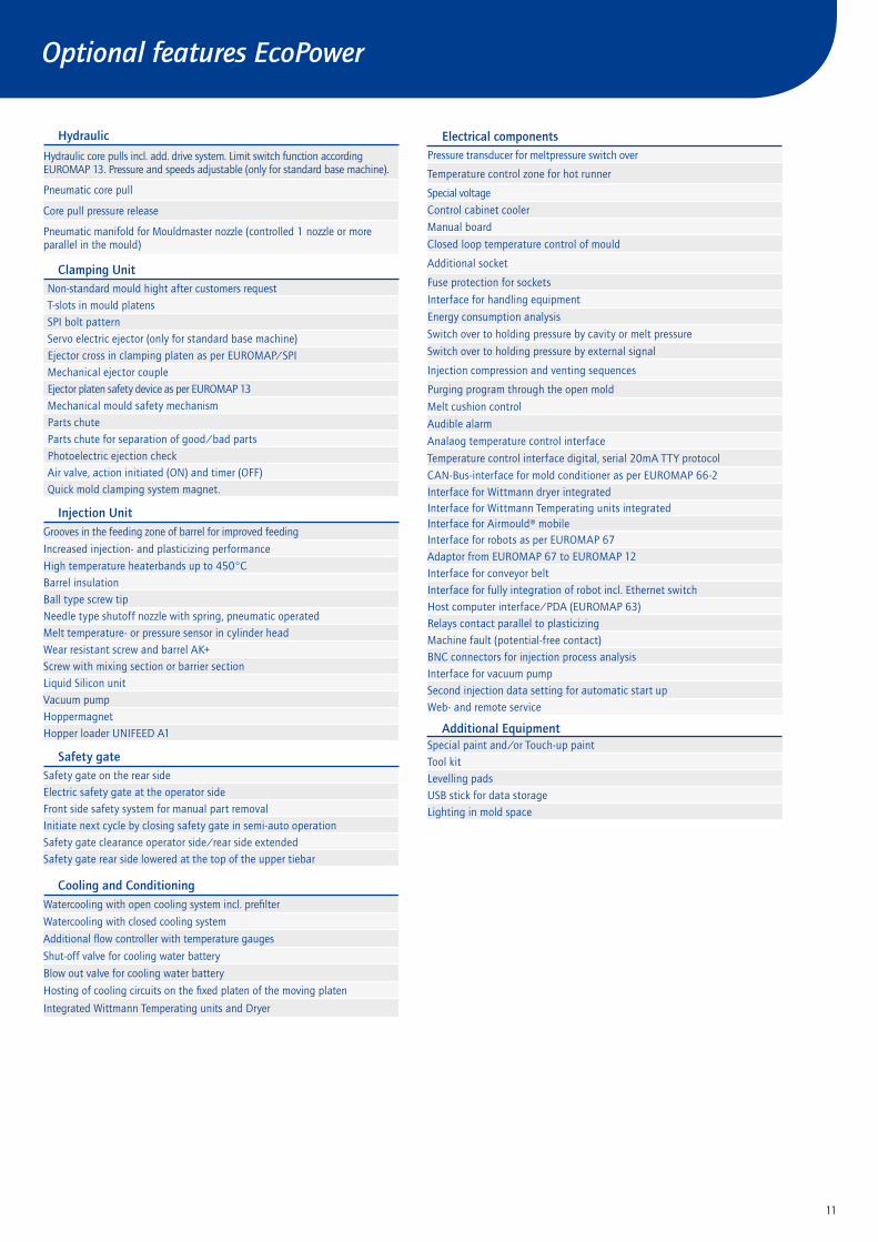
Hydraulic
Hydraulic core pulls incl. add. drive system. Limit switch function accordingEUROMAP 13. Pressure and speeds adjustable (only for standard base machine).
Pneumatic core pull
Core pull pressure release
Pneumatic manifold for Mouldmaster nozzle (controlled 1 nozzle or more parallel in the mould)
Clamping UnitNon-standard mould hight after customers request
T-slots in mould platens
SPI bolt pattern
Servo electric ejector (only for standard base machine)
Ejector cross in clamping platen as per EUROMAP/SPI
Mechanical ejector couple
Ejector platen safety device as per EUROMAP 13
Mechanical mould safety mechanism
Parts chute
Parts chute for separation of good/bad parts
Photoelectric ejection check
Air valve, action initiated (ON) and timer (OFF)
Quick mold clamping system magnet.
Injection UnitGrooves in the feeding zone of barrel for improved feeding
Increased injection- and plasticizing performance
High temperature heaterbands up to �50°C
Barrel insulation
Ball type screw tip
Needle type shutoff nozzle with spring, pneumatic operated
Melt temperature- or pressure sensor in cylinder head
Wear resistant screw and barrel AK+
Screw with mixing section or barrier section
Liquid Silicon unit
Vacuum pump
Hoppermagnet
Hopper loader UNIFEED A1
Safety gateSafety gate on the rear side
Electric safety gate at the operator side
Front side safety system for manual part removal
Initiate next cycle by closing safety gate in semi-auto operation
Safety gate clearance operator side/rear side extended
Safety gate rear side lowered at the top of the upper tiebar
Cooling and ConditioningWatercooling with open cooling system incl. prefilter
Watercooling with closed cooling system
Additional flow controller with temperature gauges
Shut-off valve for cooling water battery
Blow out valve for cooling water battery
Hosting of cooling circuits on the fixed platen of the moving platen
Integrated Wittmann Temperating units and Dryer
Electrical componentsPressure transducer for meltpressure switch over
Temperature control zone for hot runner
Special voltage
Control cabinet cooler
Manual board
Closed loop temperature control of mould
Additional socket
Fuse protection for sockets
Interface for handling equipment
Energy consumption analysis
Switch over to holding pressure by cavity or melt pressure
Switch over to holding pressure by external signal
Injection compression and venting sequences
Purging program through the open mold
Melt cushion control
Audible alarm
Analaog temperature control interface
Temperature control interface digital, serial �0mA TTY protocol
CAN-Bus-interface for mold conditioner as per EUROMAP 66-�
Interface for Wittmann dryer integratedInterface for Wittmann Temperating units integratedInterface for Airmould® mobileInterface for robots as per EUROMAP 67
Adaptor from EUROMAP 67 to EUROMAP 1�
Interface for conveyor belt
Interface for fully integration of robot incl. Ethernet switch
Host computer interface/PDA (EUROMAP 63)
Relays contact parallel to plasticizing
Machine fault (potential-free contact)
BNC connectors for injection process analysis
Interface for vacuum pump
Second injection data setting for automatic start up
Web- and remote service
Additional EquipmentSpecial paint and/or Touch-up paint
Tool kit
Levelling pads
USB stick for data storage
Lighting in mold space
Optional features EcoPower

Technology working for you.Wittmann Battenfeld GmbHWiener Neustädter Strasse 81�5�� Kottingbrunn | AustriaTel.: +�3 ��5� �0�-0 | Fax: +�3 ��5� �0�-106�[email protected]
www.wittmann-group.com
Wittmann Battenfeld GmbH & Co. KGWerner-Battenfeld-Strasse 1585�0 Meinerzhagen | GermanyTel.: +�9 �35� 7�-0 | Fax: +�9 �35� 7� �[email protected]
www.wittmann-group.com