Embed Size (px)
Citation preview
D ra f t Ope ra t ions and Ma in tenance Manua l
Vo lume 4
Soil Management Plan
Intermediate (60%) Design Submittal for the Final Groundwater Remedy
PG&E Topock Compressor Station Needles, California
Prepared for
Pacific Gas & Electric Company
April 2013
155 Grand Avenue
Suite 800 Oakland, CA 94612

SFO\130880002 iii ES070212043733BAO
Contents Section
Acronyms and Abbreviations ............................................................................................................................
Page
iii
1.0 Introduction ...................................................................................................................................... 1-1 1.1 Soil Management Plan Purpose and Objectives .............................................................................. 1-2 1.2 Site Description, Soil Investigation History, and Findings ............................................................... 1-2
1.2.1 Soil Investigation History and Findings - Outside the Compressor Station Fence Line ...... 1-5 1.2.2 Soil Investigation History and Findings - Inside the Compressor Station Fence Line ......... 1-6
1.3 Report Organization ........................................................................................................................ 1-6
2.0 Soil Management .............................................................................................................................. 2-1 2.1 Soil RFI/RI Investigation Areas Intersected by the Groundwater Remedy Project ......................... 2-1 2.2 Soil and Waste Characterization Process ........................................................................................ 2-2 2.3 Screening and Classification of Soil ................................................................................................. 2-3 2.4 Handling and Short-term Storage of Non-Hazardous Clean Soil ..................................................... 2-4 2.5 Storage of Non-Hazardous Soil ........................................................................................................ 2-4
3.0 Soil Storage ....................................................................................................................................... 3-1 3.1 Methods to Store Soil ...................................................................................................................... 3-1
3.1.1 Drums/Small Containers ..................................................................................................... 3-1 3.1.2 Stockpiles ............................................................................................................................ 3-2 3.1.3 Roll-off Bins ......................................................................................................................... 3-3
3.2 Hazardous Waste Soil Storage Time Limit ....................................................................................... 3-3 3.3 Labeling ............................................................................................................................................ 3-3
3.3.1 Hazardous Waste Soil ......................................................................................................... 3-3 3.3.2 Non-Hazardous Soil ............................................................................................................ 3-4
3.4 Inspections ....................................................................................................................................... 3-4 3.5 Security/Emergency Response ........................................................................................................ 3-4
4.0 Hazardous Waste Training, Profiling, Transportation, and Disposal ..................................................... 4-1 4.1 Employee Training for Waste Soil Management ............................................................................. 4-1 4.2 Hazardous Waste Profiling .............................................................................................................. 4-1 4.3 Manifests/Shipping Documentation................................................................................................ 4-1 4.4 Department of Transportation (DOT) Requirements ...................................................................... 4-2
4.4.1 Shipping Name .................................................................................................................... 4-2 4.4.2 Packaging, Marking, and Labeling ...................................................................................... 4-2 4.4.3 Placards ............................................................................................................................... 4-2
4.5 California Transportation Requirements ......................................................................................... 4-2 4.6 Transporter Requirements .............................................................................................................. 4-2 4.7 Spill Reporting .................................................................................................................................. 4-3 4.8 Spill Response .................................................................................................................................. 4-3 4.9 Waste Disposal ................................................................................................................................ 4-3
5.0 Recordkeeping .................................................................................................................................. 5-1
6.0 Soil Management Plan Updates ......................................................................................................... 6-1
7.0 References ........................................................................................................................................ 7-1
VOLUME 4 SOIL MANAGEMENT PLAN GROUNDWATER REMEDY DRAFT OPERATION AND MAINTENANCE MANUAL CONTENTS PG&E TOPOCK COMPRESSOR STATION, NEEDLES, CALIFORNIA
iv SFO\130880002 ES070212043733BAO
Exhibit
1.2‐1 Soil RCRA Facility Investigation/Remedial Investigation Solid Waste Management Units, Areas of Concern, and Undesignated Areas ............................................................................................................... 1‐4
Tables
1.2‐1 Historical Activities Summary, Constituents Exceeding Interim Screening Levels for Soil RFI/RI Units Outside the Fence Line, Perimeter Area, and Storm Drains, and Associated Analytical Suites ................... 1‐9
1.2‐2 Historical Area Summary and Constituents Exceeding Background Threshold Value for Soil RFI/RI Units Inside the Fence Line and Associated Analytical Suites .............................................................................. 1‐15
2.4‐1 Reference List of Potentially Applicable Analytes and Associated Screening Levels ................................... 2‐7
2.4‐2 Hazardous Waste Toxicity Characteristic Levels ......................................................................................... 2‐13
Figure
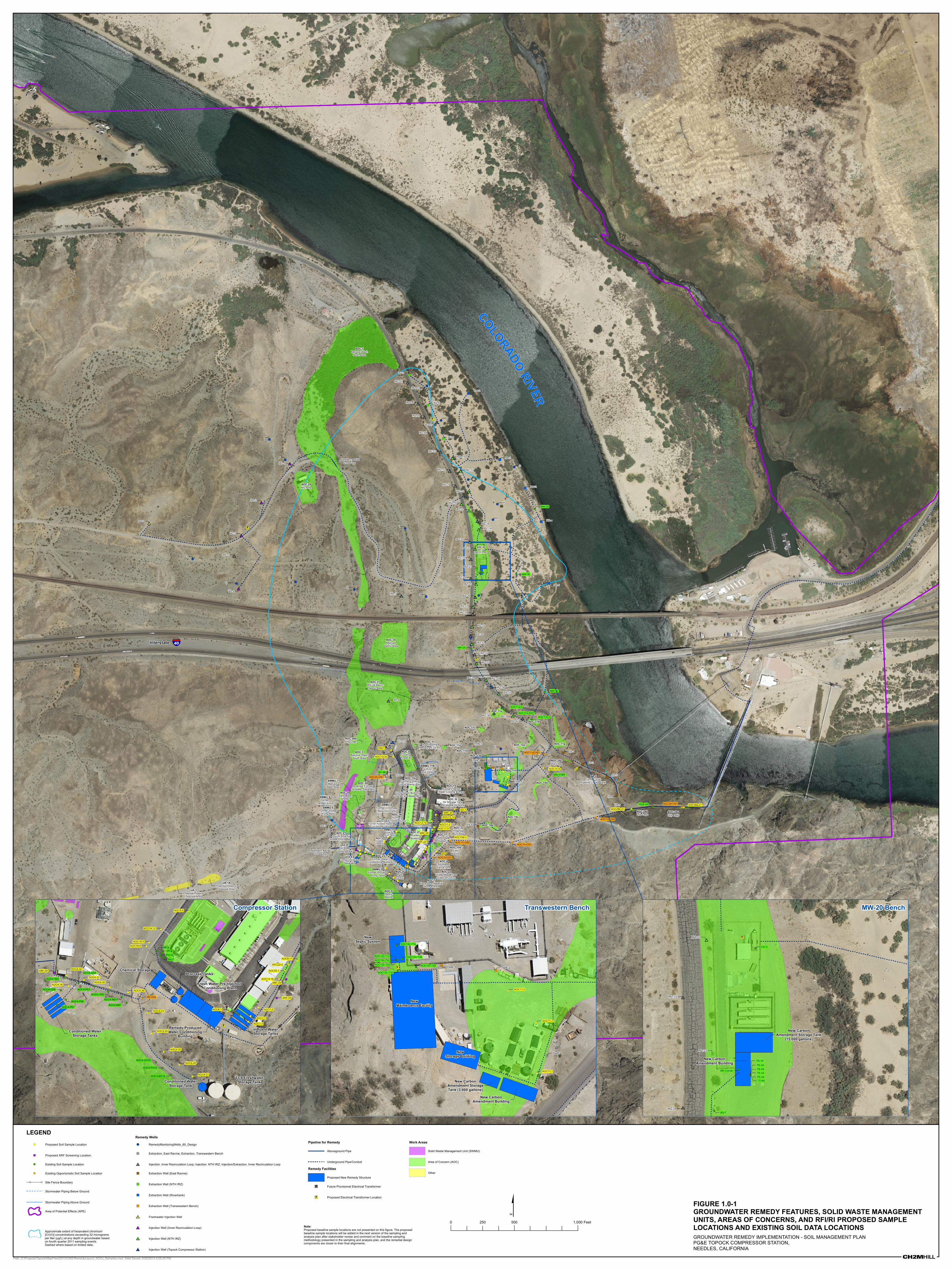
1.0‐1 Groundwater Remedy Features, Solid Waste Management Units, Areas of Concerns, and RFI/RI Proposed Sample Locations and Existing Soil Data Locations .................................................................... 1‐21
Appendices
A Groundwater Remedy Implementation—Baseline Soil Sampling and Analysis Plan
B Management Protocol for Handling and Disposition of Displaced Site Material

SFO\130880002 iii ES070212043733BAO
Acronyms and Abbreviations AOC Area of Concern
APE Area of Potential Effect
ARAR applicable or relevant and appropriate requirement
BLM U.S. Bureau of Land Management
BMP Best Management Practice
CCR California Code of Regulations
CD Consent Decree
CERCLA Comprehensive Environmental Response, Compensation, and Liability Act
CEQA California Environmental Quality Act
CFR Code of Federal Regulations
CHHSL California Human Health Screening Level
DQO Data Quality Objective
DOI U.S. Department of the Interior
DOT U.S. Department of Transportation
DTSC California Department of Toxic Substances Control
EIR environmental impact report
HAZWOPER Hazardous Waste Operations and Emergency Response
HSP Health and Safety Plan
IM-3 Interim Measure No. 3
LDR Land Disposal Restriction
mg/kg milligrams per kilogram
O&M operations and maintenance
OSHA Occupational Health and Safety Administration
PG&E Pacific Gas and Electric Company
RCRA Resource Conservation and Recovery Act
RFI RCRA Facility Investigation
RD/RA Remedial Design/Remedial Action
RI Remedial Investigation
SAP Sampling and Analysis Plan
SMP Soil Management Plan
STLC soluble threshold limit concentration
SWMU Solid Waste Management Unit
TC toxicity characteristic
VOLUME 4 SOIL MANAGEMENT PLAN GROUNDWATER REMEDY DRAFT OPERATION AND MAINTENANCE MANUAL ACRONYMS & ABBREVIATIONS PG&E TOPOCK COMPRESSOR STATION, NEEDLES, CALIFORNIA
iv SFO\130880002 ES070212043733BAO
TCLP toxicity characteristic leaching procedure
TTLC total threshold limit concentration
UA Undesignated Area
USEPA United States Environmental Protection Agency
WET Waste Extraction Test
SFO\130880002 1-1 ES070212043733BAO
SECTION 1
Introduction Pacific Gas and Electric Company (PG&E) is implementing the selected groundwater remedy to address chromium contamination in groundwater at the Topock Compressor Station (Compressor Station) in San Bernardino County, Needles, California. At some point during the implementation of the groundwater remedy, PG&E will receive approval from DTSC and DOI to decommission and remove the Interim Measures No. 3 (IM-3) Groundwater Extraction and Treatment System (referred to herein as the “IM-3 system”). The IM-3 Treatment Plant and MW-20 Bench Facility (a portion of which is part of the IM-3 system) areas have been identified as investigation areas (Areas of Concern [AOCs] 29 and AOC 30, respectively) in the concurrent Soil RCRA Facility Investigation/Remedial Investigation (RFI/RI) program.
The mitigation measure HAZ-2c set forth in the certified environmental impact report (EIR) (AECOM 2011) adopted by the California Department of Toxic Substances Control (DTSC) for the groundwater remediation project requires that contaminated soil identified during ground disturbance activities be managed and disposed of in accordance with a project-specific Soil Management Plan (SMP) and Health and Safety Plan (HSP). If activities involve stockpiling of excavated hazardous soil, this would trigger the need for compliance with the California action-specific applicable or relevant and appropriate requirement (ARAR) #86: Waste piles for RCRA hazardous waste (22 CCR, Div 4.5, Ch. 14, Article 12) (U.S. Department of the Interior [DOI] 2010), which is addressed in this SMP.
At the 60% design stage of the groundwater remediation project, proposed remedy infrastructure (i.e., exclude future provisional wells) overlaps with eighteen Soil Investigation Areas that are undergoing investigations as part of the Soil RFI/RI (see Figure 1.0-1 located at the end of this section). As shown in Figure 1.0-1, the overlap between the groundwater remediation project and ongoing soil investigations occurs in the following areas (note that as the design progresses to the 90% and final stages, the overlapping areas may change):
• Soil Investigation Areas inside the Compressor Station:
AOC 7 – Hazardous Materials Storage Area AOC 8 – Paint Locker AOC 13 – Unpaved Areas within the Compressor Station AOC 17 – Onsite Septic System AOC 18 – Combined Hazardous Waste Transference Pipelines AOC 22 – Unidentified Three-sided Structure AOC 33 – Potential Former Burn Area near AOC 17
• Soil Investigation Areas outside Compressor Station:
AOC 1 – Area Around Former Percolation Bed AOC 4 - Debris Ravine AOC 9 – Southeast Fence Line (Outside Visitor Parking Area) AOC 10 – East Ravine AOC 11 – Topographic Low Areas AOC 12 – Fill Areas AOC 27 – MW-24 Bench AOC 28 – Pipeline Drip Legs AOC 30 – MW 20 Bench Perimeter Area outside of but adjacent to the Compressor Station fence line Storm Drain System
VOLUME 4 SOIL MANAGEMENT PLAN GROUNDWATER REMEDY DRAFT OPERATION AND MAINTENANCE MANUAL 1 0BINTRODUCTION PG&E TOPOCK COMPRESSOR STATION, NEEDLES, CALIFORNIA
1-2 SFO\130880002 ES070212043733BAO
In compliance with the aforementioned EIR mitigation measure and action-specific ARAR, this SMP includes procedures and protocols for the management and disposal of potentially contaminated and contaminated soil displaced during drilling, construction, operation and maintenance (O&M) of the groundwater remedy, and the decommissioning and removal of the IM-3 system. Potentially contaminated and contaminated soil is expected to be limited to within and near the boundaries of the Soil RFI/RI Investigation Areas. This SMP is Volume 4 of the Draft O&M Manual, which is Appendix L of the Basis of Design Report for the 60% design. The HSP for O&M activities is Volume 5 of the O&M Manual, and will be submitted at the 90% design stage. The HSP for groundwater remedy construction activities will be submitted as part of the forthcoming Construction/Remedial Action Work Plan. Details of the decommissioning and removal of the IM-3 system will be submitted as part of the forthcoming IM-3 Decommissioning, Removal, and Restoration Work Plan.
Soil and material originating in or near Soil RFI/RI Investigation Areas (areas of known or suspected soil contamination) that is displaced as part of the groundwater remediation project shall be handled and managed in accordance with this SMP and the forthcoming HSPs for construction and O&M activities. Displaced soil and material originating outside areas of known or suspected contamination are assumed to be uncontaminated and will be reused as backfill into the same trench or excavation area, if practicable. Uncontaminated soil that cannot be immediately used as backfill may be reused in other areas within the Area of Potential Effect (APE), or stockpiled for future reuse within the APE. The stockpiled uncontaminated soil will be managed following the Best Management Practices (BMPs) Plan that will be submitted as part of the forthcoming Construction/Remedial Action Work Plan and the Groundwater Remedy O&M Storm Water Pollution Prevention Plan (Appendix E of Volume 1) that will be submitted as part of the 90% Basis of Design Report. In addition, handling and management of displaced soil and material from Soil RFI/RI Investigation Areas, and soil displaced as part of the decommissioning and removal of the IM-3 system shall be performed in accordance with this SMP and the forthcoming IM-3 Decommissioning, Removal, and Restoration Work Plan. Soil generated from Soil RFI/RI work activities will follow the protocols for handling of soil specified in the Revised Final Soil RFI/RI Work Plan (CH2M HILL 2013).
1.1 Soil Management Plan Purpose and Objectives The purpose and objectives of this SMP are as follows:
1. Ensure that soil is handled in a manner that complies with ARARs and the EIR mitigation measures.
2. Ensure that displaced soil from in and near Soil RFI/RI Investigation Areas that are generated during drilling, construction, decommissioning, removal, and O&M activities is handled in a manner that is protective of human health (including construction workers) and the environment within the framework of appropriate federal, state, and local requirements, and consistent with United States Environmental Protection Agency (USEPA) guidance.
3. Maximize onsite reuse of soil that was displaced during drilling, construction, decommissioning, removal, and O&M activities, following guidelines and protocols of the Management Protocol for Handling and Disposition of Displaced Site Material, Topock Remediation Project, Needles, California (PG&E 2012).
4. Minimize offsite transportation and disposal of soil that was displaced during drilling, construction, decommissioning, removal, and O&M.
5. Collect data to help guide future decision-making regarding the disposition of displaced soil and material.
1.2 Site Description, Soil Investigation History, and Findings The Compressor Station is located adjacent to the Colorado River in eastern San Bernardino County, California, approximately 12 miles southeast of Needles, California, south of Interstate 40 (I-40), in the north end of the Chemehuevi Mountains. The Topock site and adjacent lands are contained within a larger geographic area that is considered sacred by the Fort Mojave Indian Tribe and by other Native American Tribes. The Tribes believe that the environmental, cultural, and spiritual resources may not be physically perceptible. DTSC has concluded within the January 2011 certified EIR that the 779.2-acre project site “appears to qualify as a historic resource under
VOLUME 4 GROUNDWATER REMEDY DRAFT OPERATION AND MAINTENANCE MANUAL SOIL MANAGEMENT PLAN PG&E TOPOCK COMPRESSOR STATION, NEEDLES, CALIFORNIA 1 0BINTRODUCTION
SFO\130880002 1-3 ES070212043733BAO
CEQA [California Environmental Quality Act] as an area that is significant in the social and cultural annals of California,” and the U.S. Bureau of Land Management (BLM) also has determined that a traditional cultural property or property of traditional religious and cultural significance that is eligible for listing on the National Register of Historic Places exists in the area of the Topock project within the APE (AECOM 2011).
In recognition of this, all remedial activities at the Compressor Station are planned in such a way as to minimize impact to this area. Specifically, impacts to cultural resources will be minimized by implementing the mitigation measures required by the EIR. In addition, mitigation measures will be implemented in accordance with the Programmatic Agreement (PA) and the Cultural and Historic Properties Management Plan (CHPMP) and in consultation with the Tribes throughout the design process. The work will be conducted in a manner that recognizes and respects these resources and the spiritual values of the area.
Since 1996, there have been multiple phases of investigation at the Topock site to collect data to evaluate the nature and extent of contamination at the Solid Waste Management Units (SWMUs), AOCs, and Undesignated Areas (UAs). Results from the RFI/RI at the site are being documented in three volumes:
• RFI/RI Volume 1. The Revised Final RCRA Facility Investigation and Remedial Investigation Report, Volume 1 – Site Background and History (CH2M HILL 2007a) was completed in August 2007 and was approved by DTSC and DOI. Volume 1 of the RFI/RI identifies the 20 SWMUs, AOCs, and other UAs at the Topock Compressor Station to be carried forward in the Final RFI/RI.
• RFI/RI Volume 2. The Revised Final RCRA Facility Investigation/Remedial Investigation, Volume 2— Hydrogeologic Characterization and Results of Groundwater and Surface Water Investigation Report (CH2M HILL 2009a) was completed in February 2009 and approved by DTSC and DOI. Volume 2 of the RFI/RI contains the hydrogeologic characterization and results of groundwater and surface water investigations to address historical releases to groundwater from wastewater discharged at Bat Cave Wash and injection well PGE-8 at the Topock Compressor Station. The purpose of the Volume 2 RFI/RI is to complete the RFI/RI requirements for groundwater impacts associated with the past discharge of wastewater from Bat Cave Wash (SMWU 1/ AOC 1) and injection well PGE-8 (SWMU 2). An addendum to the RFI/RI Volume 2 (CH2M HILL 2009b) was submitted in June 2009. This addendum included select data and information collected between October 2007 and September 2008, after the data cutoff period for RFI/RI Volume 2.
• RFI/RI Volume 3. RFI/RI Volume 3 will include final characterization data to complete the RFI/RI requirements for remaining Topock Compressor Station operations, including results of soils investigations and the current East Ravine (AOC 10) and Compressor Station groundwater investigation. Also included in Volume 3 will be new or additional SWMUs and AOCs that have been identified after Volume 1 was finalized, including current Interim Measure No. 3 (IM-3) treatment plant location, the MW-20 bench location, buried debris found at MW-24 benches, former sulfuric acid tanks, round depression near the sludge drying beds, former three-sided structure in the upper yard, former water conditioning building, stained area associated with the former potential oil/water separator, station compressor and generator engine basements, pipeline drip legs, Teapot Dome oil pit, oil storage tank farm and waste oil sump, and burn area near AOC 17. The perimeter areas adjacent to the Compressor Station fence line and the storm drains leading from the Compressor Station to areas outside the fence line are also included in the RFI/RI Investigation and will be included in Volume 3.
PG&E will continue to document and notify the agencies of any new units discovered in the future. The SWMUs, AOCs, UAs, and other investigation areas still being characterized in support of the RFI/RI Volume 3 are presented in Exhibit 1.2-1 and shown on Figure 1.0-1.
Two draft work plans were initially prepared to describe collection of additional soil data to complete site characterization activities at the SWMUs, AOCs, and UAs identified in the Revised Final RFI/RI Volume 1 in support of RFI/RI Volume 3 preparation. Investigation areas outside the compressor station fence line were addressed in the Draft RCRA Facility Investigation/Remedial Investigation Soil Investigation Work Plan Part A, PG&E Topock Compressor Station, Needles, California (Draft Soil Part A Work Plan) (CH2M HILL 2006). Investigation areas within the compressor station fence line were addressed in the Draft RCRA Facility Investigation/Remedial Investigation
VOLUME 4 SOIL MANAGEMENT PLAN GROUNDWATER REMEDY DRAFT OPERATION AND MAINTENANCE MANUAL 1 0BINTRODUCTION PG&E TOPOCK COMPRESSOR STATION, NEEDLES, CALIFORNIA
1-4 SFO\130880002 ES070212043733BAO
Soil Investigation Work Plan Part B, PG&E Topock Compressor Station, Needles, California (Draft Part B Work Plan) (CH2M HILL 2007b).
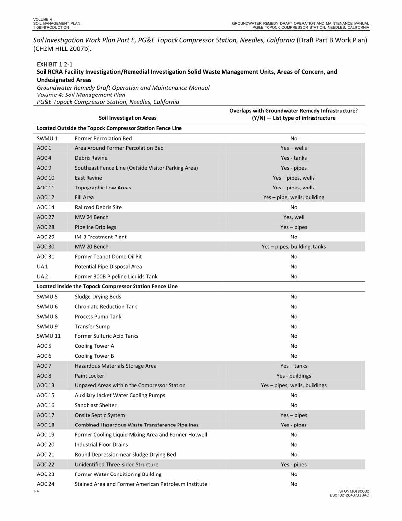
EXHIBIT 1.2-1 Soil RCRA Facility Investigation/Remedial Investigation Solid Waste Management Units, Areas of Concern, and Undesignated Areas Groundwater Remedy Draft Operation and Maintenance Manual Volume 4: Soil Management Plan PG&E Topock Compressor Station, Needles, California
Soil Investigation Areas Overlaps with Groundwater Remedy Infrastructure?
(Y/N) — List type of infrastructure
Located Outside the Topock Compressor Station Fence Line
SWMU 1 Former Percolation Bed No
AOC 1 Area Around Former Percolation Bed Yes – wells
AOC 4 Debris Ravine Yes - tanks
AOC 9 Southeast Fence Line (Outside Visitor Parking Area) Yes - pipes
AOC 10 East Ravine Yes – pipes, wells
AOC 11 Topographic Low Areas Yes – pipes, wells
AOC 12 Fill Area Yes – pipe, wells, building
AOC 14 Railroad Debris Site No
AOC 27 MW 24 Bench Yes, well
AOC 28 Pipeline Drip legs Yes – pipes
AOC 29 IM-3 Treatment Plant No
AOC 30 MW 20 Bench Yes – pipes, building, tanks
AOC 31 Former Teapot Dome Oil Pit No
UA 1 Potential Pipe Disposal Area No UA 2 Former 300B Pipeline Liquids Tank No Located Inside the Topock Compressor Station Fence Line
SWMU 5 Sludge-Drying Beds No SWMU 6 Chromate Reduction Tank No
SWMU 8 Process Pump Tank No
SWMU 9 Transfer Sump No
SWMU 11 Former Sulfuric Acid Tanks No
AOC 5 Cooling Tower A No
AOC 6 Cooling Tower B No
AOC 7 Hazardous Materials Storage Area Yes – tanks
AOC 8 Paint Locker Yes - buildings
AOC 13 Unpaved Areas within the Compressor Station Yes – pipes, wells, buildings
AOC 15 Auxiliary Jacket Water Cooling Pumps No
AOC 16 Sandblast Shelter No
AOC 17 Onsite Septic System Yes – pipes
AOC 18 Combined Hazardous Waste Transference Pipelines Yes - pipes
AOC 19 Former Cooling Liquid Mixing Area and Former Hotwell No
AOC 20 Industrial Floor Drains No
AOC 21 Round Depression near Sludge Drying Bed No
AOC 22 Unidentified Three-sided Structure Yes - pipes
AOC 23 Former Water Conditioning Building No
AOC 24 Stained Area and Former American Petroleum Institute No
VOLUME 4 GROUNDWATER REMEDY DRAFT OPERATION AND MAINTENANCE MANUAL SOIL MANAGEMENT PLAN PG&E TOPOCK COMPRESSOR STATION, NEEDLES, CALIFORNIA 1 0BINTRODUCTION
SFO\130880002 1-5 ES070212043733BAO
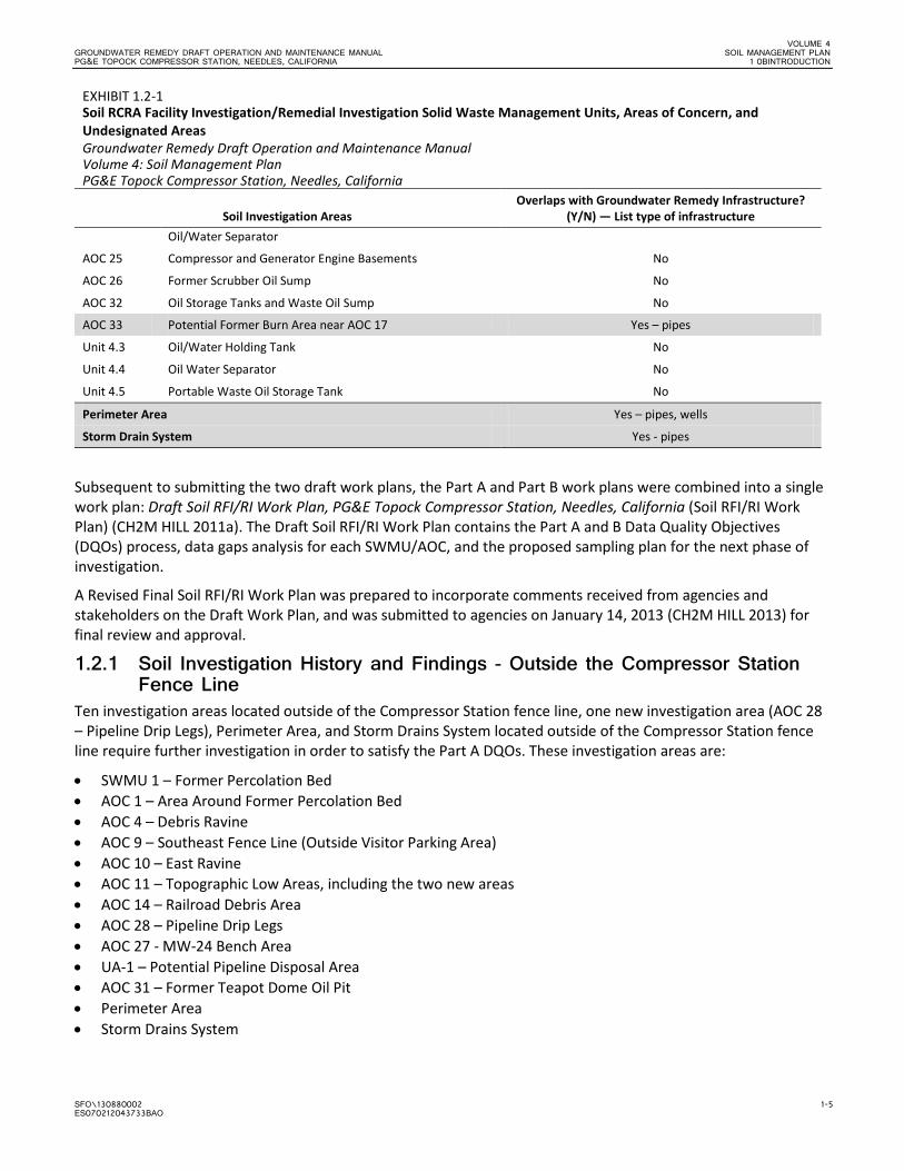
EXHIBIT 1.2-1 Soil RCRA Facility Investigation/Remedial Investigation Solid Waste Management Units, Areas of Concern, and Undesignated Areas Groundwater Remedy Draft Operation and Maintenance Manual Volume 4: Soil Management Plan PG&E Topock Compressor Station, Needles, California
Soil Investigation Areas Overlaps with Groundwater Remedy Infrastructure?
(Y/N) — List type of infrastructure Oil/Water Separator
AOC 25 Compressor and Generator Engine Basements No
AOC 26 Former Scrubber Oil Sump No
AOC 32 Oil Storage Tanks and Waste Oil Sump No
AOC 33 Potential Former Burn Area near AOC 17 Yes – pipes
Unit 4.3 Oil/Water Holding Tank No Unit 4.4 Oil Water Separator No Unit 4.5 Portable Waste Oil Storage Tank No Perimeter Area Yes – pipes, wells
Storm Drain System Yes - pipes
Subsequent to submitting the two draft work plans, the Part A and Part B work plans were combined into a single work plan: Draft Soil RFI/RI Work Plan, PG&E Topock Compressor Station, Needles, California (Soil RFI/RI Work Plan) (CH2M HILL 2011a). The Draft Soil RFI/RI Work Plan contains the Part A and B Data Quality Objectives (DQOs) process, data gaps analysis for each SWMU/AOC, and the proposed sampling plan for the next phase of investigation.
A Revised Final Soil RFI/RI Work Plan was prepared to incorporate comments received from agencies and stakeholders on the Draft Work Plan, and was submitted to agencies on January 14, 2013 (CH2M HILL 2013) for final review and approval.
1.2.1 Soil Investigation History and Findings - Outside the Compressor Station Fence Line
Ten investigation areas located outside of the Compressor Station fence line, one new investigation area (AOC 28 – Pipeline Drip Legs), Perimeter Area, and Storm Drains System located outside of the Compressor Station fence line require further investigation in order to satisfy the Part A DQOs. These investigation areas are:
• SWMU 1 – Former Percolation Bed • AOC 1 – Area Around Former Percolation Bed • AOC 4 – Debris Ravine • AOC 9 – Southeast Fence Line (Outside Visitor Parking Area) • AOC 10 – East Ravine • AOC 11 – Topographic Low Areas, including the two new areas • AOC 14 – Railroad Debris Area • AOC 28 – Pipeline Drip Legs • AOC 27 - MW-24 Bench Area • UA-1 – Potential Pipeline Disposal Area • AOC 31 – Former Teapot Dome Oil Pit • Perimeter Area • Storm Drains System
VOLUME 4 SOIL MANAGEMENT PLAN GROUNDWATER REMEDY DRAFT OPERATION AND MAINTENANCE MANUAL 1 0BINTRODUCTION PG&E TOPOCK COMPRESSOR STATION, NEEDLES, CALIFORNIA
1-6 SFO\130880002 ES070212043733BAO
The proposed sampling plan for these units is described in the Revised Final Soil RFI/RI Work Plan (CH2M HILL 2013). Table 1.2-1 (tables are presented at the end of each section) provides a summary of historical activities at the Part A investigation areas, a list of constituents that exceeded interim screening levels, and the proposed analytical suites.
1.2.2 Soil Investigation History and Findings - Inside the Compressor Station Fence Line
Twenty-four investigation areas located inside the compressor station fence line require further investigation in order to satisfy the Part B DQOs. These investigation areas are:
• SWMU 5 – Sludge-drying Beds • SWMU 6 – Chromate Reduction Tank • SWMU 8 – Process Pump Tank • SWMU 9 – Transfer Sump • SWMU 11 – Former Sulfuric Acid Tanks • AOC 5 – Cooling Tower A • AOC 6 – Cooling Tower B • AOC 7– Hazardous Materials Storage Area • AOC 8 – Paint Locker • AOC 13 – Unpaved Areas within the Compressor Station • AOC 15 – Auxiliary Jacket Cooling Water Pumps • AOC 16 – Sandblast Shelter • AOC 17 – Onsite Septic System • AOC 18 – Combined Wastewater Transference Pipelines • AOC 19 – Former Cooling Liquid Mixing Area and Former Hotwell • AOC 20 – Industrial Floor Drains • AOC 21 – Round Depression near Sludge Drying Bed • AOC 22 – Three-sided Structure • AOC 23 – Former Water Conditioning Building • AOC 24 – Stained Area and Former American Petroleum Institute Oil/Water Separator • AOC 26 – Former Scrubber Sump • AOC 33 – Potential Former Burn Area Near AOC 17 • Unit 4.3 – Oily Water Holding Tank • Unit 4.4 – Oil/Water Separator • Unit 4.5 – Portable Waste Oil Holding Tank
The proposed sampling plan for these units was described in the Revised Final Soil RFI/RI Work Plan (CH2M HILL 2013). Table 1.2-2 provides a summary of historical activities at the Part B investigation areas, a list of constituents that exceeded interim screening levels, and the proposed analytical suites.
1.3 Report Organization This SMP is organized into the following sections:
• Section 1.0 contains background information, objectives, a summary of the previous investigations conducted at the site, and a list of Soil RFI/RI Investigation Areas with overlapping groundwater remedy infrastructure.
• Section 2.0 presents details related to soil management activities including identifying areas of potential/ known contamination in the vicinity of the groundwater remedy system and IM-3 system, and the process for soil characterization, soil screening and classification, handling, and storage of soil at the site.
• Section 3.0 describes storage methods, labeling requirements and inspection of soil storage areas.
VOLUME 4 GROUNDWATER REMEDY DRAFT OPERATION AND MAINTENANCE MANUAL SOIL MANAGEMENT PLAN PG&E TOPOCK COMPRESSOR STATION, NEEDLES, CALIFORNIA 1 0BINTRODUCTION
SFO\130880002 1-7 ES070212043733BAO
• Section 4.0 summarizes the employee training required for waste soil management, hazardous waste profiling, transportation, and disposal of the various waste streams.
• Section 5.0 summarizes the records and documents that should be maintained at the site.
• Section 6.0 presents the process for updating the SMP.
• Section 7.0 presents a list of references used in the preparation of this SMP.

VOLUME 4 GROUNDWATER REMEDY DRAFT OPERATION AND MAINTENANCE MANUAL SOIL MANAGEMENT PLAN PG&E TOPOCK COMPRESSOR STATION, NEEDLES, CALIFORNIA 1 0BINTRODUCTION
SFO\130880002 1-9 ES070212043733BAO
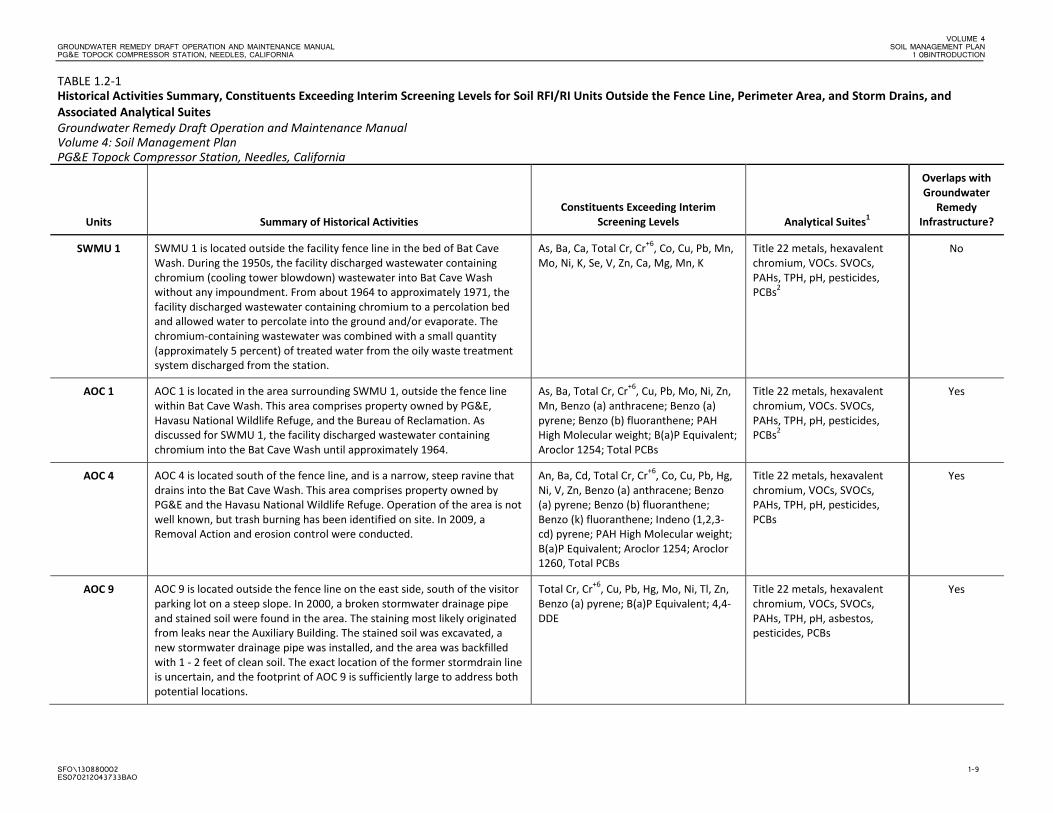
TABLE 1.2-1 Historical Activities Summary, Constituents Exceeding Interim Screening Levels for Soil RFI/RI Units Outside the Fence Line, Perimeter Area, and Storm Drains, and Associated Analytical Suites Groundwater Remedy Draft Operation and Maintenance Manual Volume 4: Soil Management Plan PG&E Topock Compressor Station, Needles, California
Units Summary of Historical Activities Constituents Exceeding Interim
Screening Levels Analytical Suites1
Overlaps with Groundwater
Remedy Infrastructure?
SWMU 1 SWMU 1 is located outside the facility fence line in the bed of Bat Cave Wash. During the 1950s, the facility discharged wastewater containing chromium (cooling tower blowdown) wastewater into Bat Cave Wash without any impoundment. From about 1964 to approximately 1971, the facility discharged wastewater containing chromium to a percolation bed and allowed water to percolate into the ground and/or evaporate. The chromium-containing wastewater was combined with a small quantity (approximately 5 percent) of treated water from the oily waste treatment system discharged from the station.
As, Ba, Ca, Total Cr, Cr+6, Co, Cu, Pb, Mn, Mo, Ni, K, Se, V, Zn, Ca, Mg, Mn, K
Title 22 metals, hexavalent chromium, VOCs. SVOCs, PAHs, TPH, pH, pesticides, PCBs2
No
AOC 1 AOC 1 is located in the area surrounding SWMU 1, outside the fence line within Bat Cave Wash. This area comprises property owned by PG&E, Havasu National Wildlife Refuge, and the Bureau of Reclamation. As discussed for SWMU 1, the facility discharged wastewater containing chromium into the Bat Cave Wash until approximately 1964.
As, Ba, Total Cr, Cr+6, Cu, Pb, Mo, Ni, Zn, Mn, Benzo (a) anthracene; Benzo (a) pyrene; Benzo (b) fluoranthene; PAH High Molecular weight; B(a)P Equivalent; Aroclor 1254; Total PCBs
Title 22 metals, hexavalent chromium, VOCs. SVOCs, PAHs, TPH, pH, pesticides, PCBs2
Yes
AOC 4 AOC 4 is located south of the fence line, and is a narrow, steep ravine that drains into the Bat Cave Wash. This area comprises property owned by PG&E and the Havasu National Wildlife Refuge. Operation of the area is not well known, but trash burning has been identified on site. In 2009, a Removal Action and erosion control were conducted.
An, Ba, Cd, Total Cr, Cr+6, Co, Cu, Pb, Hg, Ni, V, Zn, Benzo (a) anthracene; Benzo (a) pyrene; Benzo (b) fluoranthene; Benzo (k) fluoranthene; Indeno (1,2,3-cd) pyrene; PAH High Molecular weight; B(a)P Equivalent; Aroclor 1254; Aroclor 1260, Total PCBs
Title 22 metals, hexavalent chromium, VOCs, SVOCs, PAHs, TPH, pH, pesticides, PCBs
Yes
AOC 9 AOC 9 is located outside the fence line on the east side, south of the visitor parking lot on a steep slope. In 2000, a broken stormwater drainage pipe and stained soil were found in the area. The staining most likely originated from leaks near the Auxiliary Building. The stained soil was excavated, a new stormwater drainage pipe was installed, and the area was backfilled with 1 - 2 feet of clean soil. The exact location of the former stormdrain line is uncertain, and the footprint of AOC 9 is sufficiently large to address both potential locations.
Total Cr, Cr+6, Cu, Pb, Hg, Mo, Ni, Tl, Zn, Benzo (a) pyrene; B(a)P Equivalent; 4,4-DDE
Title 22 metals, hexavalent chromium, VOCs, SVOCs, PAHs, TPH, pH, asbestos, pesticides, PCBs
Yes
VOLUME 4 SOIL MANAGEMENT PLAN GROUNDWATER REMEDY DRAFT OPERATION AND MAINTENANCE MANUAL 1 0BINTRODUCTION PG&E TOPOCK COMPRESSOR STATION, NEEDLES, CALIFORNIA
1-10 SFO\130880002 ES070212043733BAO
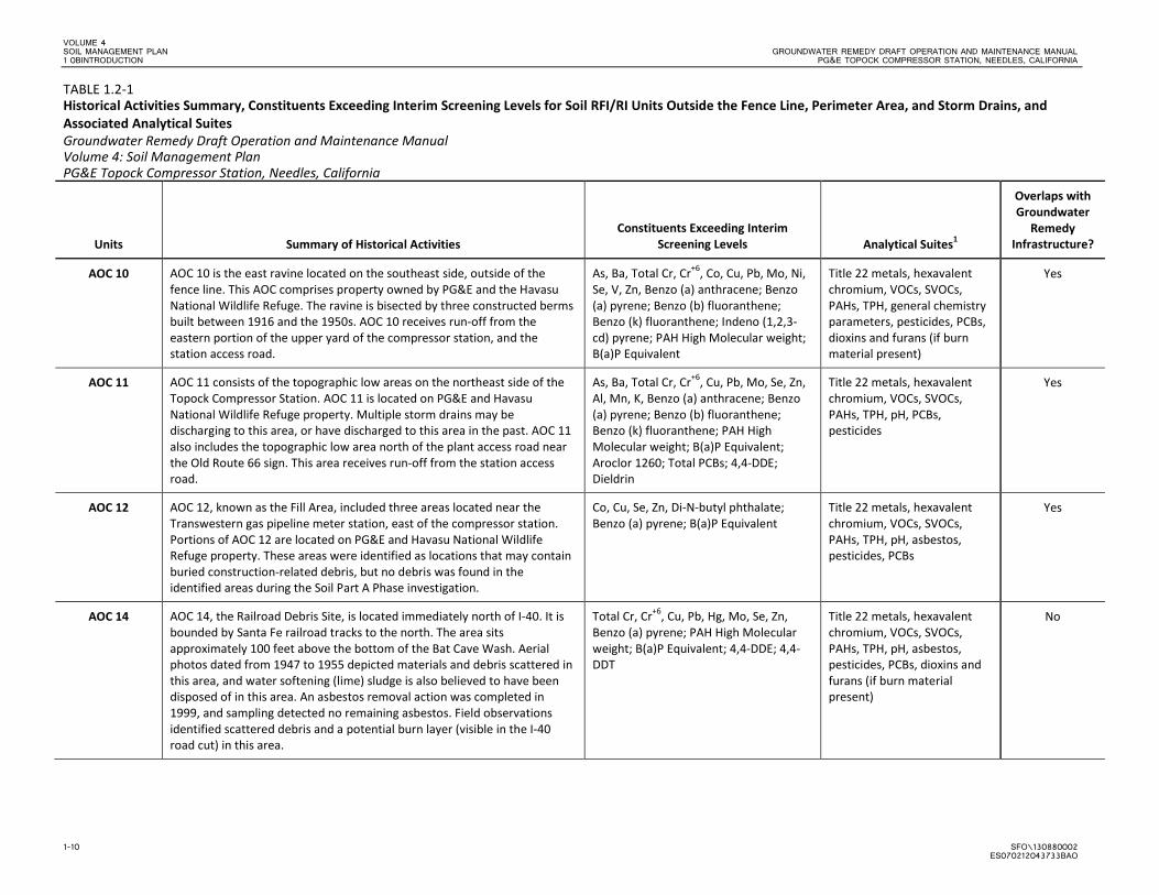
TABLE 1.2-1 Historical Activities Summary, Constituents Exceeding Interim Screening Levels for Soil RFI/RI Units Outside the Fence Line, Perimeter Area, and Storm Drains, and Associated Analytical Suites Groundwater Remedy Draft Operation and Maintenance Manual Volume 4: Soil Management Plan PG&E Topock Compressor Station, Needles, California
Units Summary of Historical Activities Constituents Exceeding Interim
Screening Levels Analytical Suites1
Overlaps with Groundwater
Remedy Infrastructure?
AOC 10 AOC 10 is the east ravine located on the southeast side, outside of the fence line. This AOC comprises property owned by PG&E and the Havasu National Wildlife Refuge. The ravine is bisected by three constructed berms built between 1916 and the 1950s. AOC 10 receives run-off from the eastern portion of the upper yard of the compressor station, and the station access road.
As, Ba, Total Cr, Cr+6, Co, Cu, Pb, Mo, Ni, Se, V, Zn, Benzo (a) anthracene; Benzo (a) pyrene; Benzo (b) fluoranthene; Benzo (k) fluoranthene; Indeno (1,2,3-cd) pyrene; PAH High Molecular weight; B(a)P Equivalent
Title 22 metals, hexavalent chromium, VOCs, SVOCs, PAHs, TPH, general chemistry parameters, pesticides, PCBs, dioxins and furans (if burn material present)
Yes
AOC 11 AOC 11 consists of the topographic low areas on the northeast side of the Topock Compressor Station. AOC 11 is located on PG&E and Havasu National Wildlife Refuge property. Multiple storm drains may be discharging to this area, or have discharged to this area in the past. AOC 11 also includes the topographic low area north of the plant access road near the Old Route 66 sign. This area receives run-off from the station access road.
As, Ba, Total Cr, Cr+6, Cu, Pb, Mo, Se, Zn, Al, Mn, K, Benzo (a) anthracene; Benzo (a) pyrene; Benzo (b) fluoranthene; Benzo (k) fluoranthene; PAH High Molecular weight; B(a)P Equivalent; Aroclor 1260; Total PCBs; 4,4-DDE; Dieldrin
Title 22 metals, hexavalent chromium, VOCs, SVOCs, PAHs, TPH, pH, PCBs, pesticides
Yes
AOC 12 AOC 12, known as the Fill Area, included three areas located near the Transwestern gas pipeline meter station, east of the compressor station. Portions of AOC 12 are located on PG&E and Havasu National Wildlife Refuge property. These areas were identified as locations that may contain buried construction-related debris, but no debris was found in the identified areas during the Soil Part A Phase investigation.
Co, Cu, Se, Zn, Di-N-butyl phthalate; Benzo (a) pyrene; B(a)P Equivalent
Title 22 metals, hexavalent chromium, VOCs, SVOCs, PAHs, TPH, pH, asbestos, pesticides, PCBs
Yes
AOC 14 AOC 14, the Railroad Debris Site, is located immediately north of I-40. It is bounded by Santa Fe railroad tracks to the north. The area sits approximately 100 feet above the bottom of the Bat Cave Wash. Aerial photos dated from 1947 to 1955 depicted materials and debris scattered in this area, and water softening (lime) sludge is also believed to have been disposed of in this area. An asbestos removal action was completed in 1999, and sampling detected no remaining asbestos. Field observations identified scattered debris and a potential burn layer (visible in the I-40 road cut) in this area.
Total Cr, Cr+6, Cu, Pb, Hg, Mo, Se, Zn, Benzo (a) pyrene; PAH High Molecular weight; B(a)P Equivalent; 4,4-DDE; 4,4-DDT
Title 22 metals, hexavalent chromium, VOCs, SVOCs, PAHs, TPH, pH, asbestos, pesticides, PCBs, dioxins and furans (if burn material present)
No
VOLUME 4 GROUNDWATER REMEDY DRAFT OPERATION AND MAINTENANCE MANUAL SOIL MANAGEMENT PLAN PG&E TOPOCK COMPRESSOR STATION, NEEDLES, CALIFORNIA 1 0BINTRODUCTION
SFO\130880002 1-11 ES070212043733BAO
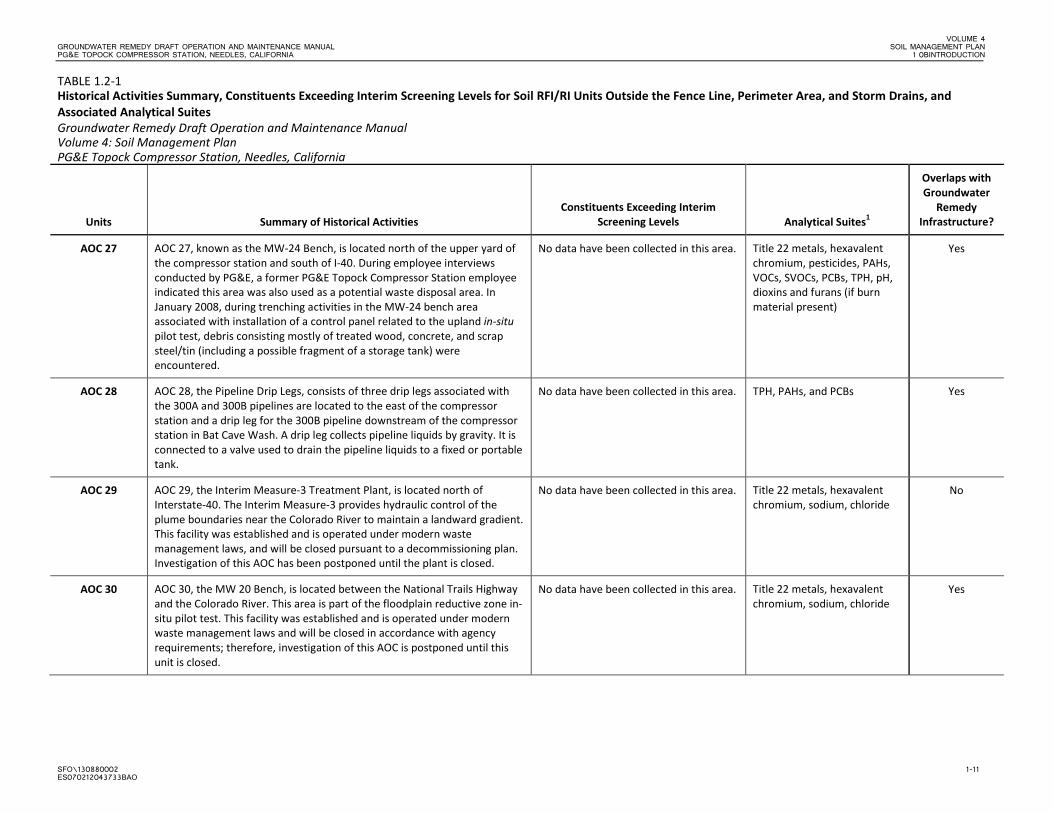
TABLE 1.2-1 Historical Activities Summary, Constituents Exceeding Interim Screening Levels for Soil RFI/RI Units Outside the Fence Line, Perimeter Area, and Storm Drains, and Associated Analytical Suites Groundwater Remedy Draft Operation and Maintenance Manual Volume 4: Soil Management Plan PG&E Topock Compressor Station, Needles, California
Units Summary of Historical Activities Constituents Exceeding Interim
Screening Levels Analytical Suites1
Overlaps with Groundwater
Remedy Infrastructure?
AOC 27 AOC 27, known as the MW-24 Bench, is located north of the upper yard of the compressor station and south of I-40. During employee interviews conducted by PG&E, a former PG&E Topock Compressor Station employee indicated this area was also used as a potential waste disposal area. In January 2008, during trenching activities in the MW-24 bench area associated with installation of a control panel related to the upland in-situ pilot test, debris consisting mostly of treated wood, concrete, and scrap steel/tin (including a possible fragment of a storage tank) were encountered.
No data have been collected in this area. Title 22 metals, hexavalent chromium, pesticides, PAHs, VOCs, SVOCs, PCBs, TPH, pH, dioxins and furans (if burn material present)
Yes
AOC 28 AOC 28, the Pipeline Drip Legs, consists of three drip legs associated with the 300A and 300B pipelines are located to the east of the compressor station and a drip leg for the 300B pipeline downstream of the compressor station in Bat Cave Wash. A drip leg collects pipeline liquids by gravity. It is connected to a valve used to drain the pipeline liquids to a fixed or portable tank.
No data have been collected in this area. TPH, PAHs, and PCBs Yes
AOC 29 AOC 29, the Interim Measure-3 Treatment Plant, is located north of Interstate-40. The Interim Measure-3 provides hydraulic control of the plume boundaries near the Colorado River to maintain a landward gradient. This facility was established and is operated under modern waste management laws, and will be closed pursuant to a decommissioning plan. Investigation of this AOC has been postponed until the plant is closed.
No data have been collected in this area. Title 22 metals, hexavalent chromium, sodium, chloride
No
AOC 30 AOC 30, the MW 20 Bench, is located between the National Trails Highway and the Colorado River. This area is part of the floodplain reductive zone in-situ pilot test. This facility was established and is operated under modern waste management laws and will be closed in accordance with agency requirements; therefore, investigation of this AOC is postponed until this unit is closed.
No data have been collected in this area. Title 22 metals, hexavalent chromium, sodium, chloride
Yes
VOLUME 4 SOIL MANAGEMENT PLAN GROUNDWATER REMEDY DRAFT OPERATION AND MAINTENANCE MANUAL 1 0BINTRODUCTION PG&E TOPOCK COMPRESSOR STATION, NEEDLES, CALIFORNIA
1-12 SFO\130880002 ES070212043733BAO
TABLE 1.2-1 Historical Activities Summary, Constituents Exceeding Interim Screening Levels for Soil RFI/RI Units Outside the Fence Line, Perimeter Area, and Storm Drains, and Associated Analytical Suites Groundwater Remedy Draft Operation and Maintenance Manual Volume 4: Soil Management Plan PG&E Topock Compressor Station, Needles, California
Units Summary of Historical Activities Constituents Exceeding Interim
Screening Levels Analytical Suites1
Overlaps with Groundwater
Remedy Infrastructure?
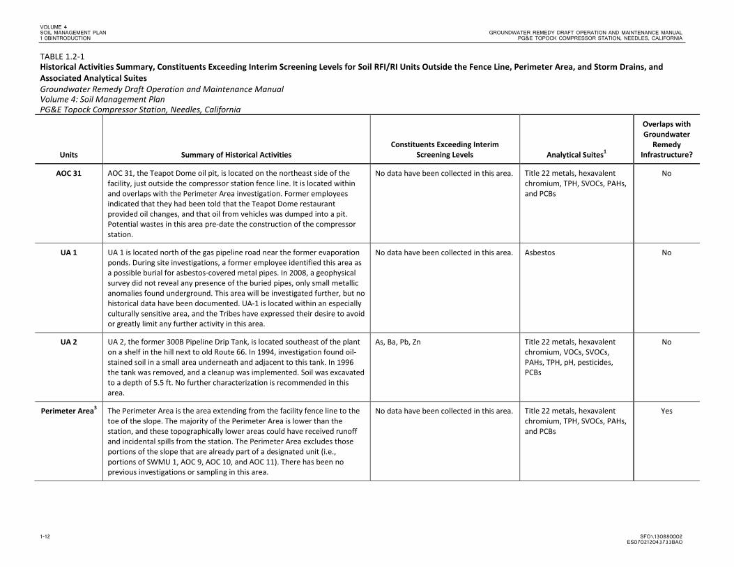
AOC 31 AOC 31, the Teapot Dome oil pit, is located on the northeast side of the facility, just outside the compressor station fence line. It is located within and overlaps with the Perimeter Area investigation. Former employees indicated that they had been told that the Teapot Dome restaurant provided oil changes, and that oil from vehicles was dumped into a pit. Potential wastes in this area pre-date the construction of the compressor station.
No data have been collected in this area. Title 22 metals, hexavalent chromium, TPH, SVOCs, PAHs, and PCBs
No
UA 1 UA 1 is located north of the gas pipeline road near the former evaporation ponds. During site investigations, a former employee identified this area as a possible burial for asbestos-covered metal pipes. In 2008, a geophysical survey did not reveal any presence of the buried pipes, only small metallic anomalies found underground. This area will be investigated further, but no historical data have been documented. UA-1 is located within an especially culturally sensitive area, and the Tribes have expressed their desire to avoid or greatly limit any further activity in this area.
No data have been collected in this area. Asbestos No
UA 2 UA 2, the former 300B Pipeline Drip Tank, is located southeast of the plant on a shelf in the hill next to old Route 66. In 1994, investigation found oil-stained soil in a small area underneath and adjacent to this tank. In 1996 the tank was removed, and a cleanup was implemented. Soil was excavated to a depth of 5.5 ft. No further characterization is recommended in this area.
As, Ba, Pb, Zn Title 22 metals, hexavalent chromium, VOCs, SVOCs, PAHs, TPH, pH, pesticides, PCBs
No
Perimeter Area3 The Perimeter Area is the area extending from the facility fence line to the toe of the slope. The majority of the Perimeter Area is lower than the station, and these topographically lower areas could have received runoff and incidental spills from the station. The Perimeter Area excludes those portions of the slope that are already part of a designated unit (i.e., portions of SWMU 1, AOC 9, AOC 10, and AOC 11). There has been no previous investigations or sampling in this area.
No data have been collected in this area. Title 22 metals, hexavalent chromium, TPH, SVOCs, PAHs, and PCBs
Yes
VOLUME 4 GROUNDWATER REMEDY DRAFT OPERATION AND MAINTENANCE MANUAL SOIL MANAGEMENT PLAN PG&E TOPOCK COMPRESSOR STATION, NEEDLES, CALIFORNIA 1 0BINTRODUCTION
SFO\130880002 1-13 ES070212043733BAO
TABLE 1.2-1 Historical Activities Summary, Constituents Exceeding Interim Screening Levels for Soil RFI/RI Units Outside the Fence Line, Perimeter Area, and Storm Drains, and Associated Analytical Suites Groundwater Remedy Draft Operation and Maintenance Manual Volume 4: Soil Management Plan PG&E Topock Compressor Station, Needles, California
Units Summary of Historical Activities Constituents Exceeding Interim
Screening Levels Analytical Suites1
Overlaps with Groundwater
Remedy Infrastructure?
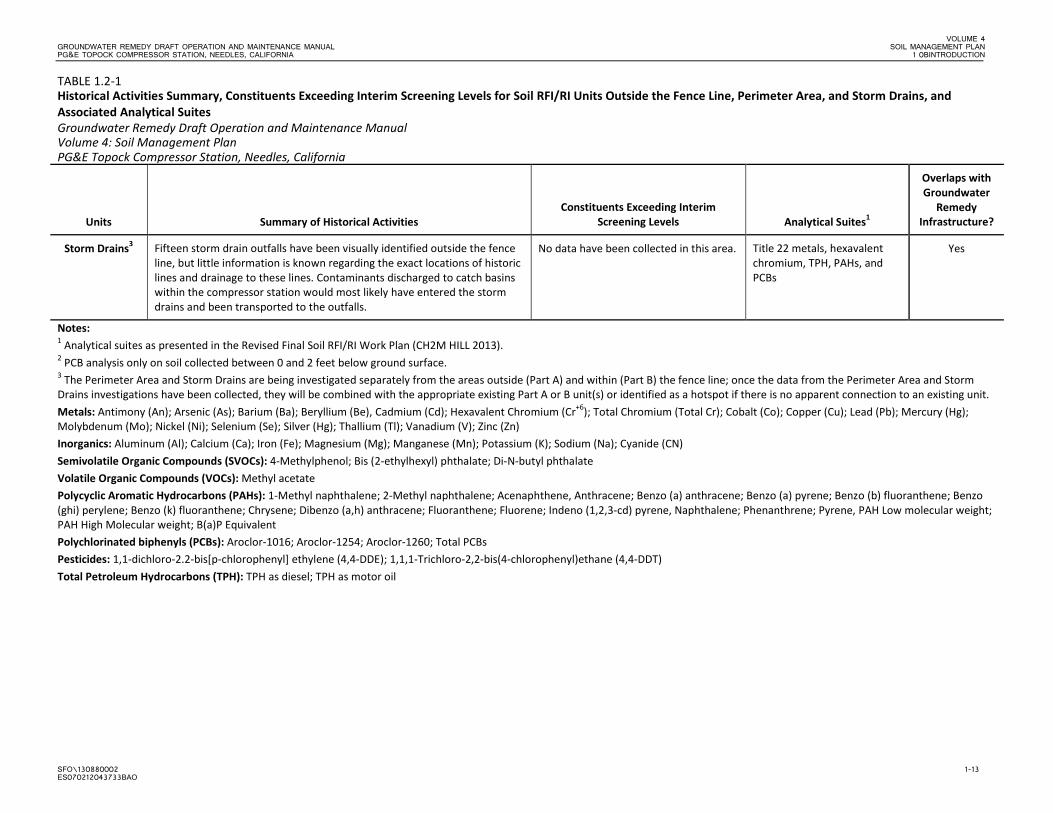
Storm Drains3 Fifteen storm drain outfalls have been visually identified outside the fence line, but little information is known regarding the exact locations of historic lines and drainage to these lines. Contaminants discharged to catch basins within the compressor station would most likely have entered the storm drains and been transported to the outfalls.
No data have been collected in this area. Title 22 metals, hexavalent chromium, TPH, PAHs, and PCBs
Yes
Notes: 1 Analytical suites as presented in the Revised Final Soil RFI/RI Work Plan (CH2M HILL 2013). 2 PCB analysis only on soil collected between 0 and 2 feet below ground surface. 3 The Perimeter Area and Storm Drains are being investigated separately from the areas outside (Part A) and within (Part B) the fence line; once the data from the Perimeter Area and Storm Drains investigations have been collected, they will be combined with the appropriate existing Part A or B unit(s) or identified as a hotspot if there is no apparent connection to an existing unit. Metals: Antimony (An); Arsenic (As); Barium (Ba); Beryllium (Be), Cadmium (Cd); Hexavalent Chromium (Cr+6); Total Chromium (Total Cr); Cobalt (Co); Copper (Cu); Lead (Pb); Mercury (Hg); Molybdenum (Mo); Nickel (Ni); Selenium (Se); Silver (Hg); Thallium (Tl); Vanadium (V); Zinc (Zn) Inorganics: Aluminum (Al); Calcium (Ca); Iron (Fe); Magnesium (Mg); Manganese (Mn); Potassium (K); Sodium (Na); Cyanide (CN) Semivolatile Organic Compounds (SVOCs): 4-Methylphenol; Bis (2-ethylhexyl) phthalate; Di-N-butyl phthalate Volatile Organic Compounds (VOCs): Methyl acetate Polycyclic Aromatic Hydrocarbons (PAHs): 1-Methyl naphthalene; 2-Methyl naphthalene; Acenaphthene, Anthracene; Benzo (a) anthracene; Benzo (a) pyrene; Benzo (b) fluoranthene; Benzo (ghi) perylene; Benzo (k) fluoranthene; Chrysene; Dibenzo (a,h) anthracene; Fluoranthene; Fluorene; Indeno (1,2,3-cd) pyrene, Naphthalene; Phenanthrene; Pyrene, PAH Low molecular weight; PAH High Molecular weight; B(a)P Equivalent Polychlorinated biphenyls (PCBs): Aroclor-1016; Aroclor-1254; Aroclor-1260; Total PCBs Pesticides: 1,1-dichloro-2.2-bis[p-chlorophenyl] ethylene (4,4-DDE); 1,1,1-Trichloro-2,2-bis(4-chlorophenyl)ethane (4,4-DDT) Total Petroleum Hydrocarbons (TPH): TPH as diesel; TPH as motor oil

VOLUME 4 GROUNDWATER REMEDY DRAFT OPERATION AND MAINTENANCE MANUAL SOIL MANAGEMENT PLAN PG&E TOPOCK COMPRESSOR STATION, NEEDLES, CALIFORNIA 1 0BINTRODUCTION
SFO\130880002 1-15 ES070212043733BAO
TABLE 1.2-2 Historical Area Summary and Constituents Exceeding Background Threshold Value for Soil RFI/RI Units Inside the Fence Line and Associated Analytical Suites Groundwater Remedy Draft Operation and Maintenance Manual Volume 4: Soil Management Plan PG&E Topock Compressor Station, Needles, California
Units Summary of Historical Activities
Constituents Exceeding Background Threshold
Value Analytical Suites1
Overlaps with Groundwater
Remedy Infrastructure?
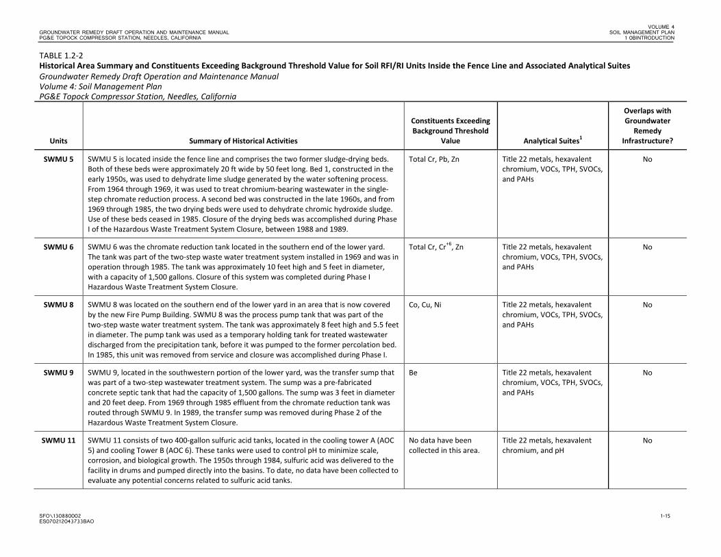
SWMU 5 SWMU 5 is located inside the fence line and comprises the two former sludge-drying beds. Both of these beds were approximately 20 ft wide by 50 feet long. Bed 1, constructed in the early 1950s, was used to dehydrate lime sludge generated by the water softening process. From 1964 through 1969, it was used to treat chromium-bearing wastewater in the single-step chromate reduction process. A second bed was constructed in the late 1960s, and from 1969 through 1985, the two drying beds were used to dehydrate chromic hydroxide sludge. Use of these beds ceased in 1985. Closure of the drying beds was accomplished during Phase I of the Hazardous Waste Treatment System Closure, between 1988 and 1989.
Total Cr, Pb, Zn Title 22 metals, hexavalent chromium, VOCs, TPH, SVOCs, and PAHs
No
SWMU 6 SWMU 6 was the chromate reduction tank located in the southern end of the lower yard. The tank was part of the two-step waste water treatment system installed in 1969 and was in operation through 1985. The tank was approximately 10 feet high and 5 feet in diameter, with a capacity of 1,500 gallons. Closure of this system was completed during Phase I Hazardous Waste Treatment System Closure.
Total Cr, Cr+6, Zn Title 22 metals, hexavalent chromium, VOCs, TPH, SVOCs, and PAHs
No
SWMU 8 SWMU 8 was located on the southern end of the lower yard in an area that is now covered by the new Fire Pump Building. SWMU 8 was the process pump tank that was part of the two-step waste water treatment system. The tank was approximately 8 feet high and 5.5 feet in diameter. The pump tank was used as a temporary holding tank for treated wastewater discharged from the precipitation tank, before it was pumped to the former percolation bed. In 1985, this unit was removed from service and closure was accomplished during Phase I.
Co, Cu, Ni Title 22 metals, hexavalent chromium, VOCs, TPH, SVOCs, and PAHs
No
SWMU 9 SWMU 9, located in the southwestern portion of the lower yard, was the transfer sump that was part of a two-step wastewater treatment system. The sump was a pre-fabricated concrete septic tank that had the capacity of 1,500 gallons. The sump was 3 feet in diameter and 20 feet deep. From 1969 through 1985 effluent from the chromate reduction tank was routed through SWMU 9. In 1989, the transfer sump was removed during Phase 2 of the Hazardous Waste Treatment System Closure.
Be Title 22 metals, hexavalent chromium, VOCs, TPH, SVOCs, and PAHs
No
SWMU 11 SWMU 11 consists of two 400-gallon sulfuric acid tanks, located in the cooling tower A (AOC 5) and cooling Tower B (AOC 6). These tanks were used to control pH to minimize scale, corrosion, and biological growth. The 1950s through 1984, sulfuric acid was delivered to the facility in drums and pumped directly into the basins. To date, no data have been collected to evaluate any potential concerns related to sulfuric acid tanks.
No data have been collected in this area.
Title 22 metals, hexavalent chromium, and pH
No
VOLUME 4 SOIL MANAGEMENT PLAN GROUNDWATER REMEDY DRAFT OPERATION AND MAINTENANCE MANUAL 1 0BINTRODUCTION PG&E TOPOCK COMPRESSOR STATION, NEEDLES, CALIFORNIA
1-16 SFO\130880002 ES070212043733BAO
TABLE 1.2-2 Historical Area Summary and Constituents Exceeding Background Threshold Value for Soil RFI/RI Units Inside the Fence Line and Associated Analytical Suites Groundwater Remedy Draft Operation and Maintenance Manual Volume 4: Soil Management Plan PG&E Topock Compressor Station, Needles, California
Units Summary of Historical Activities
Constituents Exceeding Background Threshold
Value Analytical Suites1
Overlaps with Groundwater
Remedy Infrastructure?
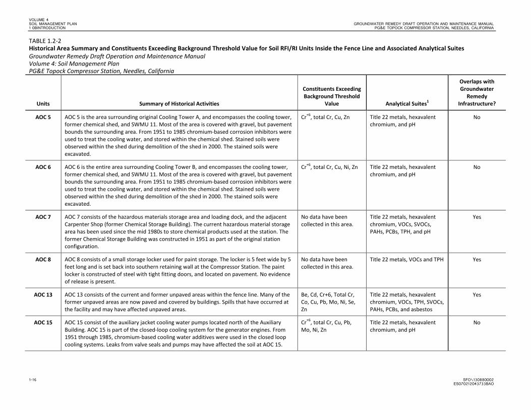
AOC 5 AOC 5 is the area surrounding original Cooling Tower A, and encompasses the cooling tower, former chemical shed, and SWMU 11. Most of the area is covered with gravel, but pavement bounds the surrounding area. From 1951 to 1985 chromium-based corrosion inhibitors were used to treat the cooling water, and stored within the chemical shed. Stained soils were observed within the shed during demolition of the shed in 2000. The stained soils were excavated.
Cr+6, total Cr, Cu, Zn Title 22 metals, hexavalent chromium, and pH
No
AOC 6 AOC 6 is the entire area surrounding Cooling Tower B, and encompasses the cooling tower, former chemical shed, and SWMU 11. Most of the area is covered with gravel, but pavement bounds the surrounding area. From 1951 to 1985 chromium-based corrosion inhibitors were used to treat the cooling water, and stored within the chemical shed. Stained soils were observed within the shed during demolition of the shed in 2000. The stained soils were excavated.
Cr+6, total Cr, Cu, Ni, Zn Title 22 metals, hexavalent chromium, and pH
No
AOC 7 AOC 7 consists of the hazardous materials storage area and loading dock, and the adjacent Carpenter Shop (former Chemical Storage Building). The current hazardous material storage area has been used since the mid 1980s to store chemical products used at the station. The former Chemical Storage Building was constructed in 1951 as part of the original station configuration.
No data have been collected in this area.
Title 22 metals, hexavalent chromium, VOCs, SVOCs, PAHs, PCBs, TPH, and pH
Yes
AOC 8 AOC 8 consists of a small storage locker used for paint storage. The locker is 5 feet wide by 5 feet long and is set back into southern retaining wall at the Compressor Station. The paint locker is constructed of steel with tight fitting doors, and located on pavement. No evidence of release is present.
No data have been collected in this area.
Title 22 metals, VOCs and TPH Yes
AOC 13 AOC 13 consists of the current and former unpaved areas within the fence line. Many of the former unpaved areas are now paved and covered by buildings. Spills that have occurred at the facility and may have affected unpaved areas.
Be, Cd, Cr+6, Total Cr, Co, Cu, Pb, Mo, Ni, Se, Zn
Title 22 metals, hexavalent chromium, VOCs, TPH, SVOCs, PAHs, PCBs, and asbestos
Yes
AOC 15 AOC 15 consist of the auxiliary jacket cooling water pumps located north of the Auxiliary Building. AOC 15 is part of the closed-loop cooling system for the generator engines. From 1951 through 1985, chromium-based cooling water additives were used in the closed loop cooling systems. Leaks from valve seals and pumps may have affected the soil at AOC 15.
Cr+6, total Cr, Cu, Pb, Mo, Ni, Zn
Title 22 metals, hexavalent chromium, and pH
No
VOLUME 4 GROUNDWATER REMEDY DRAFT OPERATION AND MAINTENANCE MANUAL SOIL MANAGEMENT PLAN PG&E TOPOCK COMPRESSOR STATION, NEEDLES, CALIFORNIA 1 0BINTRODUCTION
SFO\130880002 1-17 ES070212043733BAO
TABLE 1.2-2 Historical Area Summary and Constituents Exceeding Background Threshold Value for Soil RFI/RI Units Inside the Fence Line and Associated Analytical Suites Groundwater Remedy Draft Operation and Maintenance Manual Volume 4: Soil Management Plan PG&E Topock Compressor Station, Needles, California
Units Summary of Historical Activities
Constituents Exceeding Background Threshold
Value Analytical Suites1
Overlaps with Groundwater
Remedy Infrastructure?
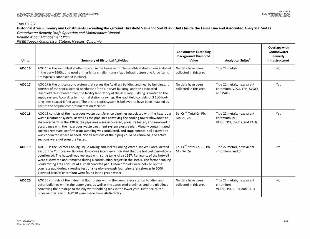
AOC 16 AOC 16 is the sand blast shelter located in the lower yard. The sandblast shelter was installed in the early 1990s, and used primarily for smaller items (fixed infrastructure and large items are typically sandblasted in place).
No data have been collected in this area.
Title 22 metals No
AOC 17 AOC 17 is the onsite septic system that serves the Auxiliary Building and nearby buildings. It consists of the septic located northeast of the air dryer building, and the associated leachfield. Wastewater from the facility laboratory of the Auxiliary Building is routed to the septic system. According to informal station drawings, the leachfield consists of 3 100-foot-long lines spaced 6 feet apart. The onsite septic system is believed to have been installed as part of the original compressor station facilities.
No data have been collected in this area.
Title 22 metals, hexavalent chromium, VOCs, TPH, SVOCs, and PAHs
Yes
AOC 18 AOC 18 consists of the hazardous waste transference pipelines associated with the hazardous waste treatment system, as well as the pipelines conveying the cooling tower blowdown to the lower yard. In the 1980s, the pipelines were uncovered, pressure tested, and removed in accordance with the hazardous waste treatment system closure plan. Visually contaminated soil was removed, confirmation sampling was conducted, and supplemental soil excavation was conducted where needed. Not all sections of the piping could be removed, and active sections were not pressure tested.
Be, Cr+6, Total Cr, Pb, Mo, Ni, Zn
Title 22 metals, hexavalent chromium, pH, VOCs, TPH, SVOCs, and PAHs
Yes
AOC 19 AOC 19 is the Former Cooling Liquid Mixing and Jacket Cooling Water Hot Well Area located east of the Compressor Building. Employee interviews indicated that the hot well periodically overflowed. The hotwell was replaced with surge tanks circa 1967. Remnants of the hotwell were discovered and removed during a construction project in the 1990s. The former cooling liquid mixing area consists of a small concrete pad. Green droplets were noticed on the concrete pad during a routine test of a nearby eyewash fountain/safety shower in 2006. Elevated level of chromium were found in the green water.
Cd, Cr+6, total Cr, Cu, Pb, Mo, Se, Zn
Title 22 metals, hexavalent chromium, and pH
No
AOC 20 AOC 20 consists of the industrial floor drains within the compressor station building and other buildings within the upper yard, as well as the associated pipelines, and the pipelines conveying the drainage to the oily water holding tank in the lower yard. Historically, the pipes associate with AOC 20 were made from vitrified clay.
No data have been collected in this area.
Title 22 metals, hexavalent chromium, VOCs, TPH, PCBs, and PAHs
No
VOLUME 4 SOIL MANAGEMENT PLAN GROUNDWATER REMEDY DRAFT OPERATION AND MAINTENANCE MANUAL 1 0BINTRODUCTION PG&E TOPOCK COMPRESSOR STATION, NEEDLES, CALIFORNIA
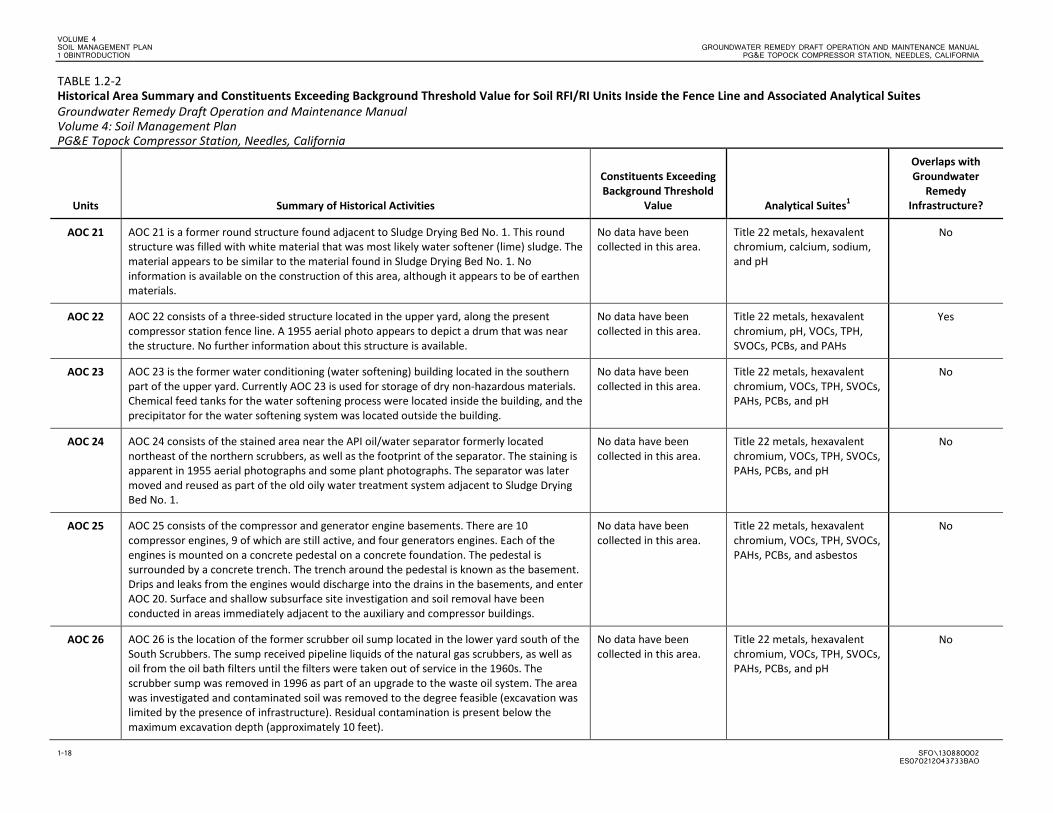
1-18 SFO\130880002 ES070212043733BAO
TABLE 1.2-2 Historical Area Summary and Constituents Exceeding Background Threshold Value for Soil RFI/RI Units Inside the Fence Line and Associated Analytical Suites Groundwater Remedy Draft Operation and Maintenance Manual Volume 4: Soil Management Plan PG&E Topock Compressor Station, Needles, California
Units Summary of Historical Activities
Constituents Exceeding Background Threshold
Value Analytical Suites1
Overlaps with Groundwater
Remedy Infrastructure?
AOC 21 AOC 21 is a former round structure found adjacent to Sludge Drying Bed No. 1. This round structure was filled with white material that was most likely water softener (lime) sludge. The material appears to be similar to the material found in Sludge Drying Bed No. 1. No information is available on the construction of this area, although it appears to be of earthen materials.
No data have been collected in this area.
Title 22 metals, hexavalent chromium, calcium, sodium, and pH
No
AOC 22 AOC 22 consists of a three-sided structure located in the upper yard, along the present compressor station fence line. A 1955 aerial photo appears to depict a drum that was near the structure. No further information about this structure is available.
No data have been collected in this area.
Title 22 metals, hexavalent chromium, pH, VOCs, TPH, SVOCs, PCBs, and PAHs
Yes
AOC 23 AOC 23 is the former water conditioning (water softening) building located in the southern part of the upper yard. Currently AOC 23 is used for storage of dry non-hazardous materials. Chemical feed tanks for the water softening process were located inside the building, and the precipitator for the water softening system was located outside the building.
No data have been collected in this area.
Title 22 metals, hexavalent chromium, VOCs, TPH, SVOCs, PAHs, PCBs, and pH
No
AOC 24 AOC 24 consists of the stained area near the API oil/water separator formerly located northeast of the northern scrubbers, as well as the footprint of the separator. The staining is apparent in 1955 aerial photographs and some plant photographs. The separator was later moved and reused as part of the old oily water treatment system adjacent to Sludge Drying Bed No. 1.
No data have been collected in this area.
Title 22 metals, hexavalent chromium, VOCs, TPH, SVOCs, PAHs, PCBs, and pH
No
AOC 25 AOC 25 consists of the compressor and generator engine basements. There are 10 compressor engines, 9 of which are still active, and four generators engines. Each of the engines is mounted on a concrete pedestal on a concrete foundation. The pedestal is surrounded by a concrete trench. The trench around the pedestal is known as the basement. Drips and leaks from the engines would discharge into the drains in the basements, and enter AOC 20. Surface and shallow subsurface site investigation and soil removal have been conducted in areas immediately adjacent to the auxiliary and compressor buildings.
No data have been collected in this area.
Title 22 metals, hexavalent chromium, VOCs, TPH, SVOCs, PAHs, PCBs, and asbestos
No
AOC 26 AOC 26 is the location of the former scrubber oil sump located in the lower yard south of the South Scrubbers. The sump received pipeline liquids of the natural gas scrubbers, as well as oil from the oil bath filters until the filters were taken out of service in the 1960s. The scrubber sump was removed in 1996 as part of an upgrade to the waste oil system. The area was investigated and contaminated soil was removed to the degree feasible (excavation was limited by the presence of infrastructure). Residual contamination is present below the maximum excavation depth (approximately 10 feet).
No data have been collected in this area.
Title 22 metals, hexavalent chromium, VOCs, TPH, SVOCs, PAHs, PCBs, and pH
No
VOLUME 4 GROUNDWATER REMEDY DRAFT OPERATION AND MAINTENANCE MANUAL SOIL MANAGEMENT PLAN PG&E TOPOCK COMPRESSOR STATION, NEEDLES, CALIFORNIA 1 0BINTRODUCTION
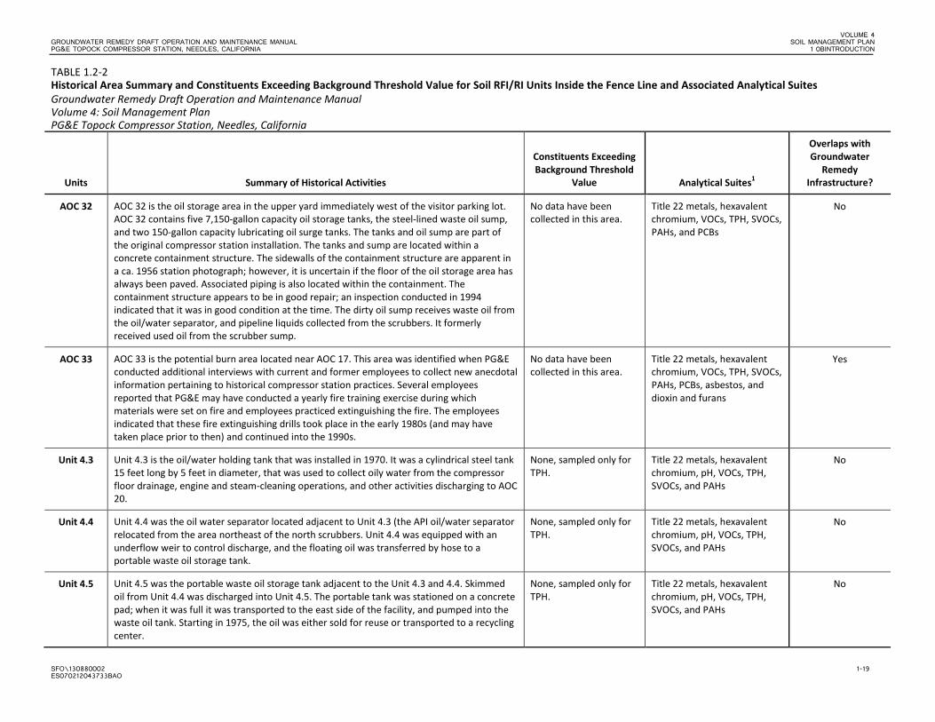
SFO\130880002 1-19 ES070212043733BAO
TABLE 1.2-2 Historical Area Summary and Constituents Exceeding Background Threshold Value for Soil RFI/RI Units Inside the Fence Line and Associated Analytical Suites Groundwater Remedy Draft Operation and Maintenance Manual Volume 4: Soil Management Plan PG&E Topock Compressor Station, Needles, California
Units Summary of Historical Activities
Constituents Exceeding Background Threshold
Value Analytical Suites1
Overlaps with Groundwater
Remedy Infrastructure?
AOC 32 AOC 32 is the oil storage area in the upper yard immediately west of the visitor parking lot. AOC 32 contains five 7,150-gallon capacity oil storage tanks, the steel-lined waste oil sump, and two 150-gallon capacity lubricating oil surge tanks. The tanks and oil sump are part of the original compressor station installation. The tanks and sump are located within a concrete containment structure. The sidewalls of the containment structure are apparent in a ca. 1956 station photograph; however, it is uncertain if the floor of the oil storage area has always been paved. Associated piping is also located within the containment. The containment structure appears to be in good repair; an inspection conducted in 1994 indicated that it was in good condition at the time. The dirty oil sump receives waste oil from the oil/water separator, and pipeline liquids collected from the scrubbers. It formerly received used oil from the scrubber sump.
No data have been collected in this area.
Title 22 metals, hexavalent chromium, VOCs, TPH, SVOCs, PAHs, and PCBs
No
AOC 33 AOC 33 is the potential burn area located near AOC 17. This area was identified when PG&E conducted additional interviews with current and former employees to collect new anecdotal information pertaining to historical compressor station practices. Several employees reported that PG&E may have conducted a yearly fire training exercise during which materials were set on fire and employees practiced extinguishing the fire. The employees indicated that these fire extinguishing drills took place in the early 1980s (and may have taken place prior to then) and continued into the 1990s.
No data have been collected in this area.
Title 22 metals, hexavalent chromium, VOCs, TPH, SVOCs, PAHs, PCBs, asbestos, and dioxin and furans
Yes
Unit 4.3 Unit 4.3 is the oil/water holding tank that was installed in 1970. It was a cylindrical steel tank 15 feet long by 5 feet in diameter, that was used to collect oily water from the compressor floor drainage, engine and steam-cleaning operations, and other activities discharging to AOC 20.
None, sampled only for TPH.
Title 22 metals, hexavalent chromium, pH, VOCs, TPH, SVOCs, and PAHs
No
Unit 4.4 Unit 4.4 was the oil water separator located adjacent to Unit 4.3 (the API oil/water separator relocated from the area northeast of the north scrubbers. Unit 4.4 was equipped with an underflow weir to control discharge, and the floating oil was transferred by hose to a portable waste oil storage tank.
None, sampled only for TPH.
Title 22 metals, hexavalent chromium, pH, VOCs, TPH, SVOCs, and PAHs
No
Unit 4.5 Unit 4.5 was the portable waste oil storage tank adjacent to the Unit 4.3 and 4.4. Skimmed oil from Unit 4.4 was discharged into Unit 4.5. The portable tank was stationed on a concrete pad; when it was full it was transported to the east side of the facility, and pumped into the waste oil tank. Starting in 1975, the oil was either sold for reuse or transported to a recycling center.
None, sampled only for TPH.
Title 22 metals, hexavalent chromium, pH, VOCs, TPH, SVOCs, and PAHs
No
VOLUME 4 SOIL MANAGEMENT PLAN GROUNDWATER REMEDY DRAFT OPERATION AND MAINTENANCE MANUAL 1 0BINTRODUCTION PG&E TOPOCK COMPRESSOR STATION, NEEDLES, CALIFORNIA
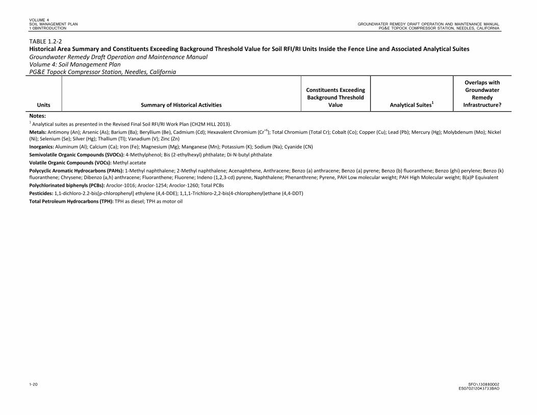
1-20 SFO\130880002 ES070212043733BAO
TABLE 1.2-2 Historical Area Summary and Constituents Exceeding Background Threshold Value for Soil RFI/RI Units Inside the Fence Line and Associated Analytical Suites Groundwater Remedy Draft Operation and Maintenance Manual Volume 4: Soil Management Plan PG&E Topock Compressor Station, Needles, California
Units Summary of Historical Activities
Constituents Exceeding Background Threshold
Value Analytical Suites1
Overlaps with Groundwater
Remedy Infrastructure?
Notes: 1 Analytical suites as presented in the Revised Final Soil RFI/RI Work Plan (CH2M HILL 2013). Metals: Antimony (An); Arsenic (As); Barium (Ba); Beryllium (Be), Cadmium (Cd); Hexavalent Chromium (Cr+6); Total Chromium (Total Cr); Cobalt (Co); Copper (Cu); Lead (Pb); Mercury (Hg); Molybdenum (Mo); Nickel (Ni); Selenium (Se); Silver (Hg); Thallium (Tl); Vanadium (V); Zinc (Zn) Inorganics: Aluminum (Al); Calcium (Ca); Iron (Fe); Magnesium (Mg); Manganese (Mn); Potassium (K); Sodium (Na); Cyanide (CN) Semivolatile Organic Compounds (SVOCs): 4-Methylphenol; Bis (2-ethylhexyl) phthalate; Di-N-butyl phthalate Volatile Organic Compounds (VOCs): Methyl acetate Polycyclic Aromatic Hydrocarbons (PAHs): 1-Methyl naphthalene; 2-Methyl naphthalene; Acenaphthene, Anthracene; Benzo (a) anthracene; Benzo (a) pyrene; Benzo (b) fluoranthene; Benzo (ghi) perylene; Benzo (k) fluoranthene; Chrysene; Dibenzo (a,h) anthracene; Fluoranthene; Fluorene; Indeno (1,2,3-cd) pyrene, Naphthalene; Phenanthrene; Pyrene, PAH Low molecular weight; PAH High Molecular weight; B(a)P Equivalent Polychlorinated biphenyls (PCBs): Aroclor-1016; Aroclor-1254; Aroclor-1260; Total PCBs Pesticides: 1,1-dichloro-2.2-bis[p-chlorophenyl] ethylene (4,4-DDE); 1,1,1-Trichloro-2,2-bis(4-chlorophenyl)ethane (4,4-DDT) Total Petroleum Hydrocarbons (TPH): TPH as diesel; TPH as motor oil
"S
#B
#B
#B
#B#B
#B
#B#B
#B
#B
#B
#B
#B
#B
#B
#B
#B
#B
#B
#B
#B
#B#B
"S
"S
!H
!H!H
!H
!H !H
!H
!H
!H
!H
!H
!H
!H
!H
!H
!H
!H
!H
!H"!
"!
"!
"!
"!
"!
"!
"S
"S
"S
#B
#B
#B
#B#B
#B
#B
#B
"S
#B
#B
#B
#B
#B
#B
#B
#B
"S
"S
"S
"S
"S
#B
#B
#B
#B
"S "S
"S
"S
"S
"S
"S
#B
#B
#B
#B
Ü
Ü
Ü
Ü
Ü
Ü
Ü
ÜÜ
Ü
ÜÜ
ÜÜ Ü Ü Ü ÜÜ
Ü
Ü
Ü
Ü
Ü
Ü
Ü
Ü
Ü
Ü
Ü
Ü
Ü
Ü ÜÜ
Ü
Ü
Ü
Ü
Ü
Ü
Ü
ÜÜÜ
ÜÜ
Ü
ÜÜ
Ü
Ü
Ü
Ü
ÜÜ
Ü
Ü
ÜÜ
Ü
Ü
Ü
Ü Ü
Ü
ÜÜÜÜ
ÜÜ
Ü
Ü
ÜÜ
Ü
Ü
Ü
ÜÜ
Ü
Ü
Ü
ÜÜ
Ü
Ü
Ü
Ü
Ü
Ü
Ü
ÜÜ
Ü Ü
Ü
ÜÜ
Ü
Ü
Ü
Ü
Ü
Ü
Ü
Ü
Ü
Ü
!(
!(
!(
!(
!(!( !(!(!(!(
!(!(!(!(
!(!(!(!(!(!(
!(
!(
!(!(
!(
!(
!(
!(!(
!(!(
!(
!(!(
!(
!(
!(
!(
!(
!(!(
!(
!(
!(
!(
!(
!(
!(
!(
!(
!(!(
!(
!(
!(!(!(
!(
!(
!(!(
!(!(
!(
!(!(
!(
!(
GF
GF
GF
GF
GF
GF !(
!(
!(
!(
!(
!(!(
!(
!(!(
!(!(
!(
!(
!(
!(
!(
!(
!(
!(!(!(
!(
!(
!(
!(!(
!(!(
!(
!(!(
!(
!(
GF
GF
GF
GF
GF
GF !(
!(
!(
!(
!(
!(!(
!(
!(!(
!(!(
!(
!(
!(
!(
!(
!(
!(
!(
!(
§̈¦40Interstate
COLORADO RIVER
Northern AerialCrossing
Northern AerialCrossing SD-1
AOC 30MW-20
Bench Area
AOC 11a
AOC 11b
AOC 12aAOC 11d
AOC 7Hazardous Material
Storage Area
AOC 5CoolingTower A
SWMU 6Former ChromateReduction Tank
SWMU 9Former
Transfer Sump
Unit 4.4Former Oil/Water
SeparatorSWMU 8
Former ProcessPump Tank
AOC 8Paint
Locker
AOC 6CoolingTower B
AOC 1Batcave Wash
South Area
AOC 4DebrisRavine
SWMU 5Former Sludge
Drying Beds
Unit 4.3Oil Water
Holding Tank
AOC 10d
AOC 10c
AOC 10b
AOC 9SoutheastFence Line
UA-1Potential Pipeline
Disposal Area
AOC 10aEast
Ravine
AOC 11e
AOC 16Sand Blast
Shelter
AOC 12b
UA-1APotential Pipeline
Disposal Area
AOC 12c
UA-2Former 300b
Pipeline Liquids Tank
AOC 11c
AOC 17Onsite Septic
System
AOC 15Auxiliary Jacket
Water Cooling Pumps
AOC 14Railroad
Debris Area
AOC 11g
AOC 11f
AOC 24Potential Former
Oil/Water Separator AOC 25Compressor Building
Engines and Basements
AOC 23Former Water
Conditioning Building
AOC 21Round Area by
Sludge Drying Beds
AOC 22Unidentified Three
Sided Structure
SWMU 11NSulfuric
Acid Tanks
SWMU 11SSulfuric
Acid Tanks
SWMU 1Batcave
Wash Area
AOC 19Former Cooling
Liquid Mixing Area
AOC 26Former
Scrubber Sump
UA-1BPotential Pipeline
Disposal Area
AOC 25AuxilaryBuilding
AOC 28aDrip Legs
AOC 28bDrip Legs
AOC 28cDrip Legs
AOC 28dDrip Legs
AOC 29IM3 Area
AOC 1Batcave Wash
North Area
AOC 27MW-24 Bench
Debris Area
AOC 31Teapot Dome
Restaurant Oil Pit
AOC 33Potential
Burn Area
AOC 32Oil Storage Tank
and Waste Oil Sump
Unit 4.5Former Portable Waste
Oil Storage Tank
J
R
M
N E
F
G
K
S
L
D
H
C
O
P
I
A
B
Q
ER-5
IRL-5
IRL-6
IRL-7
IRZ-02
IRZ-03
IRZ-04
IRZ-06
IRZ-07
IRZ-08
IRZ-10
IRZ-12
IRZ-14
IRZ-18
IRZ-22
IRZ-24
IRZ-26
IRZ-28
IRZ-30
IRZ-32
IRZ-34
IRZ-36
IRZ-38IRZ-40
TWB-3
TWB-4
IRZ-1
IRZ-5
IRZ-9
IRZ-11
IRZ-13
IRZ-15
IRZ-16
IRZ-17
IRZ-19
IRZ-20
IRZ-21
IRZ-23
IRZ-25
IRZ-27
IRZ-29
IRZ-31
IRZ-33
IRZ-35
IRZ-37
IRZ-39
RB-1
RB-2
RB-3
RB-4
RB-5
IRL-1
IRL-2
IRL-3
IRL-4
TWB-1TWB-2
ER-1
ER-2
ER-3
ER-4
ER-6
TCS-1
TCS-2
FW-1
FW-2
AOC24-OS1
AOC28-OS1
AOC11g-OS1
AOC10-OS1
AOC10-OS2 AOC10-OS3
AOC10-OS4
AOC11a-SS3AOC11a-4
AOC11b-1
MW-57BRBH-66
300a-29
MW-28
MW-26
MW-22
MW-30
AOC13-16AOC13-12
AOC17-4AOC17-2
AOC13-30
XRF-25
XRF-26
XRF-30SD-7
AOC10a-3
AOC10-9
AOC28b-01AOC28a-01
PA01
LEGEND!( Proposed Soil Sample Location
GF Proposed XRF Screening Location
!( Existing Soil Sample Location
!( Existing Opportunistic Soil Sample Location
Ü Ü Site Fence Boundary
Stormwater Piping Below Ground
Stormwater Piping Above Ground
Area of Potential Effects (APE)
!H RemedyMonitoringWells_60_Design
"S Extraction, East Ravine; Extraction, Transwestern Bench
#B Injection, Inner Recirculation Loop; Injection, NTH IRZ; Injection/Extraction, Inner Recirculation Loop
"S Extraction Well (East Ravine)
"S Extraction Well (NTH IRZ)
"S Extraction Well (Riverbank)
"S Extraction Well (Transwestern Bench)
#B Freshwater Injection Well
#B Injection Well (Inner Recirculation Loop)
#B Injection Well (NTH IRZ)
#B Injection Well (Topock Compressor Station)
Pipeline for Remedy
Aboveground Pipe
Underground Pipe/ConduitRemedy Facilities
Proposed New Remedy Structure
"! Future Provisional Electrical Transformer
"! Proposed Electrical Transformer Location
Work Areas
Solid Waste Management Unit (SWMU)
Area of Concern (AOC)
Other
Path: D:\Projects\Topock\MapFiles\2013\CMS\RemedyLayout_AOCs_Samples.mxd Date Saved: 3/26/2013 4:05:26 PM
0 500 1,000250 Feet$ FIGURE 1.0-1
GROUNDWATER REMEDY FEATURES, SOLID WASTE MANAGEMENTUNITS, AREAS OF CONCERNS, AND RFI/RI PROPOSED SAMPLELOCATIONS AND EXISTING SOIL DATA LOCATIONSGROUNDWATER REMEDY IMPLEMENTATION - SOIL MANAGEMENT PLANPG&E TOPOCK COMPRESSOR STATION,NEEDLES, CALIFORNIA
"!
!(
!(
!(
!(
!(!(!(
!(
!(
!(
"S
"S
"S
NewMaintenance Facility
NewStorage Building
New CarbonAmendment Building
New CarbonAmendment StorageTank (3,000 gallons)
NewSeptic System
TWB-2
TWB-4
TWB-1
AOC12c-T1a
AOC12c-T1b
AOC12c-T1c
AOC12c-T2a
AOC12c-T2bAOC12c-T2cAOC12c-T2d
AOC11-2
AOC11-1
AOC11-3
Ü
Ü
Ü
Ü
Ü
Ü
ÜÜ
ÜÜ
ÜÜ
Ü
Ü
Ü
Ü
Ü
Ü
Ü
Ü
Ü
Ü
Ü
Ü
Ü
Ü
Ü
Ü
Ü
Ü
Ü
Ü
Ü
Ü
Ü
Ü
"!
!(!(
!(!(
!(
!(
!(
!(
!(
!(
!(
!(
!(
!(
!(
!(
!(
!(
!( !(
!(
!(
!(
!(
!(
!(
!(
!(
!(
!(
!(
!(
!(
GF
GF
GF
GF
GF
!(
!(
!(
!(
!(
!(
!(
!(
!(
!(
!(
!(
Chemical Storage
Fresh Water Pre-InjectionConditioning Plant
Remedy-ProducedWater Conditioning
BuildingInfluent WaterStorage TanksConditioned Water
Storage Tanks
Conditioned WaterStorage Tank
TCS FreshwaterStorage Tank
Proccess Tanks
PF-6PF-8
PH-12PH-7
AOC4-F01S
AOC4-G01S
AOC4-E01S
AOC4-P03
AOC4-M01AOC4-N01
AOC4-O02
AOC4-P06AOC4-P07
AOC4-Q04
AOC4-Q06
AOC4-R05
PA-OS2
AOC5-5
AOC8-1
AOC7-1AOC7-2
AOC13-18
AOC18-6AOC18-5
AOC22-2
AOC22-1
AOC7-5
AOC18-12
XRF-23
XRF-24
XRF-20
AOC9-17
AOC4-32
AOC4-18
AOC4-31AOC4-30
AOC4-29
AOC4-23
AOC4-24
AOC4-25
AOC4-26
AOC4-27
Note:Proposed baseline sample locations are not presented on this figure. The proposedbaseline sample locations will be added in the next version of the sampling andanalysis plan after stakeholder review and comment on the baseline samplingmethodology presented in the sampling and analysis plan, and the remedial designcomponents are closer to their final alignments.
"!
!(!(!(!(!(!(
!(
!(
!(
#B
#B
#B
#B
"S
#B
New CarbonAmendment Storage Tank
(15,000 gallons)
New CarbonAmendment Building
IRZ-21
IRZ-23
IRZ-24
IRZ-22
TS-1ATS-2ATS-3ATS-4ATS-5ATS-6A
BG-7
SW-Corner
CS13
Transwestern Bench MW-20 BenchCompressor Station
Approximate extent of hexavalent chromium[Cr(VI)] concentrations exceeding 32 microgramsper liter (μg/L) at any depth in groundwater basedon fourth quarter 2011 sampling events.Dashed where based on limited data.
Remedy Wells

SFO\130880002 2-1 ES070212043733BAO
SECTION 2
Soil Management Soil that may be displaced in or near Soil RFI/RI Investigation Areas during drilling, construction, and O&M activities that are part of the groundwater remediation project or decommissioning and removal of the IM-3 system will be managed according to the processes described in this SMP. This section identifies Soil RFI/RI Investigation Areas in the vicinity of the groundwater remedy system and IM-3 system, and describes the processes for soil characterization, soil screening and classification, handling, short-term storage, and longer storage of displaced soil.
The process presented herein for determining whether displaced soil (including drill cuttings) is hazardous waste, is in compliance with California action-specific ARAR #74 (22 CCR Section 66262.11), Requirements for Waste Determination (DOI 2010). Once determined to be a hazardous waste, the waste shall be managed in compliance with California action-specific ARARs #75 through #80, and #84 through #86 (DOI 2010):
• ARAR #75 (22 CCR 66262.12): USEPA identification number
• ARAR #76 (22 CCR, Div 4.5, Ch 14, Article 2): General requirements for hazardous waste facilities
• ARAR #77 (22 CCR 66262.20 and 66262.22): Use of hazardous waste manifest
• ARAR #78 (22 CCR 66262.30, 66262.31, 66262.32 and 66262.33): Packaging, marking, labeling, and placarding hazardous waste shipments
• ARAR #79 (22 CCR 66262.34): Accumulation requirements for hazardous waste
• ARAR #80 (22 CCR 66262.40 and 66262.41): Recordkeeping
• ARAR #84 (22 CCR, Div 4.5, Ch 14, Article 9): Use and management of containers
• ARAR #85 (22 CCR, Div 4.5, Ch 14, Article 10): Tank systems
• ARAR #86 (22 CCR, Div 4.5, Ch 14, Article 12): Waste piles for RCRA hazardous waste
In addition, to maximize onsite reuse of displaced soil and minimize offsite transportation and disposal of site soil, characterization, screening, handling, and storage processes were developed following guidelines in the Management Protocol for Handling and Disposition of Displaced Site Material, Topock Remediation Project, Needles, California (PG&E 2012).
2.1 Soil RFI/RI Investigation Areas Intersected by the Groundwater Remedy Project
As of the 60% design stage, proposed remedy pipeline/conduit alignments (includes direct burial pipelines/ conduits, pipeline trenches, and remediation wells [i.e., injection and extraction wells] that are connected to those pipelines), remedy structures, and new monitoring well will intersect eighteen Soil RFI/RI Investigation Areas. These areas are listed below and shown on Figure 1.0-1:
• AOC 1 – Area Around Former Percolation Bed • AOC 4 - Debris Ravine • AOC 7 – Hazardous Materials Storage Area • AOC 8 – Paint Locker • AOC 9 – Southeast Fence Line (Outside Visitor Parking Area) • AOC 10 – East Ravine • AOC 11 – Topographic Low Areas • AOC 12 – Fill Areas • AOC 13 – Unpaved Areas within the Compressor Station
VOLUME 4 SOIL MANAGEMENT PLAN GROUNDWATER REMEDY DRAFT OPERATION AND MAINTENANCE MANUAL 2 1BSOIL MANAGEMENT PG&E TOPOCK COMPRESSOR STATION, NEEDLES, CALIFORNIA
2-2 SFO\130880002 ES070212043733BAO
• AOC 17 – Onsite Septic System • AOC 18 – Combined Hazardous Waste Transference Pipelines • AOC 22 – Unidentified Three-sided Structure • AOC 27 – MW-24 Bench • AOC 28 – Pipeline Drip Legs • AOC 30 – MW 20 Bench • AOC 33 – Potential Former Burn Area near AOC 17 • Perimeter Area outside of but adjacent to the Compressor Station fence line • Storm Drain System
The decommissioning and removal of the IM-3 system will affect two AOCs - AOC 29 (IM-3 Treatment Plant) and AOC 30 (MW 20 Bench).
These Soil RFI/RI Investigation Areas are currently being investigated under the Soil RFI/RI program. Tables 1.2-1 and 1.2-2 provide a summary of historical activities at each of these investigation areas, a list of constituents that exceeded interim screening levels, and the proposed analytical suites as presented in the revised Soil FRI/RI Work Plan. Existing soil data collected from within AOCs will be used to assess required protection of workers for health and safety purposes. Personnel engaged in field activities within known AOC areas will have completed the Occupational Safety Health Administration 40-hour health and safety training that meet the requirements of Title 29 CFR Section 1910.120 and Title 8 CCR Section 5192. All personnel will read applicable project-specific health and safety plans.
2.2 Soil and Waste Characterization Process Soil in or near Soil RFI/RI Investigation Areas that are in the vicinity of the groundwater remedy system expected to be displaced will be pre-characterized following the Groundwater Remedy Implementation—Baseline Soil Sampling and Analysis Plan (Baseline SAP), included as Appendix A of this document. The baseline soil sampling results will be screened following the process described below in Section 2.4 to classify the displaced soil for handling, storage, and/or disposal purposes. Soil generated during construction and O&M in or near Soil RFI/RI Investigation Areas that have not been pre-characterized and during the decommissioning and removal of the IM-3 system will be stockpiled or placed in lined roll-off bins at the work site, if practicable, or onsite in a temporary storage area designated by PG&E until they have been characterized.
Field segregation of soil will be a key step in the process of management of displaced soil for any ground disturbance activities that occur during remedy construction. As soil is displaced, any soil with odors or visual evidence of contamination will be segregated, characterized, and handled following procedures outlined in this SMP.
Existing soil sample results and knowledge of the area history will be used to assess waste classification for displaced soil that has not been pre-characterized. Additional characterization of displaced soil from or near Soil RFI/RI Investigation Areas will be performed as needed. In general, characterization will entail collection of composite samples from roll-off bins and stockpiles. One four-point composite sample will be taken from each roll-off bin. For stockpiles, the number of representative samples to be collected will be as follows unless otherwise directed by the disposal facility:
Stockpile Volume Frequency
0 to 500 cy Four-point composite per 250 cy
500 to 1,500 cy Four-point composite per 500 cy
1,500+ cy Four-point composite per 1,500 cy Source: Alisto et al. 2009 cy = cubic yard
VOLUME 4 GROUNDWATER REMEDY DRAFT OPERATION AND MAINTENANCE MANUAL SOIL MANAGEMENT PLAN PG&E TOPOCK COMPRESSOR STATION, NEEDLES, CALIFORNIA 2 1BSOIL MANAGEMENT
SFO\130880002 2-3 ES070212043733BAO
The waste characterization soil samples will be analyzed for the applicable Soil RFI/RI Investigation Area analytical suite presented in Tables 1.2-1 and 1.2-2. Analytical results will be screened according to the procedure listed in Section 2.4 to classify the soil for handling, storage, and disposal purposes. It is imperative to coordinate with the waste hauler and disposal facility to ensure proper completion of the profile.
Drill cuttings from new monitoring, extraction, and injection well locations will not be fully characterized as part of the Baseline SAP; therefore, drill cuttings from monitoring wells installed in or near Soil RFI/RI Investigation Areas will be containerized in 55-gallon U.S. Department of Transportation (DOT) drums or lined roll-off bins. The drill cuttings drums/bins will be stored onsite in a temporary storage area designated by PG&E until they have been characterized. Drum and roll-off bin storage are described in Section 3.1.
Characterization of drilling cuttings will be performed by collection of one discrete sample per 55-gallon DOT drum or at least one composite per ten drums, or one composite sample from each roll-off bin. One sample will be taken from the center of each drum from at least 12 inches below the surface of the soil. For multiple drum characterization, discrete drum samples will be composited for up to 10 drums. One four-point composite sample will be taken from each roll-off bin. The samples will be analyzed for applicable Soil RFI/RI Investigation Area analytical suite presented in Tables 1.2-1 and 1.2-2. Analytical results will be screened according to the procedure listed in Section 2.4 to classify the soil for handling, storage, and disposal purposes.
2.3 Screening and Classification of Soil The following process for screening and classification of displaced soil in compliance with California action-specific ARAR #74 (22 CCR 66262.11) is based on the Management Protocol for Handling and Disposition of Displaced Site Material, Topock Remediation Project, Needles, California (PG&E 2012) (see Appendix B).
Analytical results from the Baseline SAP or other characterization of soil samples (i.e., drum or roll-off bins, or areas not pre-characterized) will be used to assess whether displaced soil is suitable for retention onsite for eventual return, reuse, or replacement, or if the soil must be removed from the site for disposal in accordance with applicable state and federal laws and regulations. Analytes detected in the Baseline SAP or other characterization of soil samples above laboratory detection limits will be screened against the screening values included on Tables 2.4-1 and 2.4-2. These screening values include the following:
• Interim Screening Levels (Table 2.4-1) – The screening levels for metals are predominantly Topock-specific soil background values. However, if a background value is not available then the lesser of the DTSC residential California Human Health Screening Level (CHHSL) or the ecological comparison value is used. If a CHHSL is not available, then the lesser of the USEPA residential regional screening level or the ecological comparison value is used. These levels are the most conservative, and it is assumed that the project-specific soil cleanup goal will be equal to or greater than these levels.
• Hazardous Waste Toxicity Characteristic Levels (Table 2.4-2) – These values will be used to assess if the soil should be classified as a non-hazardous waste, a state (non-RCRA California) hazardous waste, or a federal (RCRA) hazardous waste. Specifically, total constituent concentrations expressed in milligrams per kilogram (mg/kg) will be compared to the hazardous waste characteristic levels in Table 2.4-2, and will be evaluated as follows:
- Step 1 - If the total constituent concentration exceeds the total threshold limit concentration (TTLC), the soil represented by the sample will be classified as a non-RCRA hazardous waste. Additional evaluation of the soluble threshold limit concentration (STLC), as described in Step 3 below, will not be performed.
- Step 2 - If the total constituent concentration exceeds the numeric value of the RCRA toxicity characteristic (TC) level by about 20 times or more, the toxicity characteristic leaching procedure (TCLP) will be performed. If the constituent concentration in the TCLP leachate exceeds the TC level, the soil represented by the sample will be classified as a RCRA hazardous waste. Additional evaluation of the STLC, as described in Step 3 below, will not be performed.
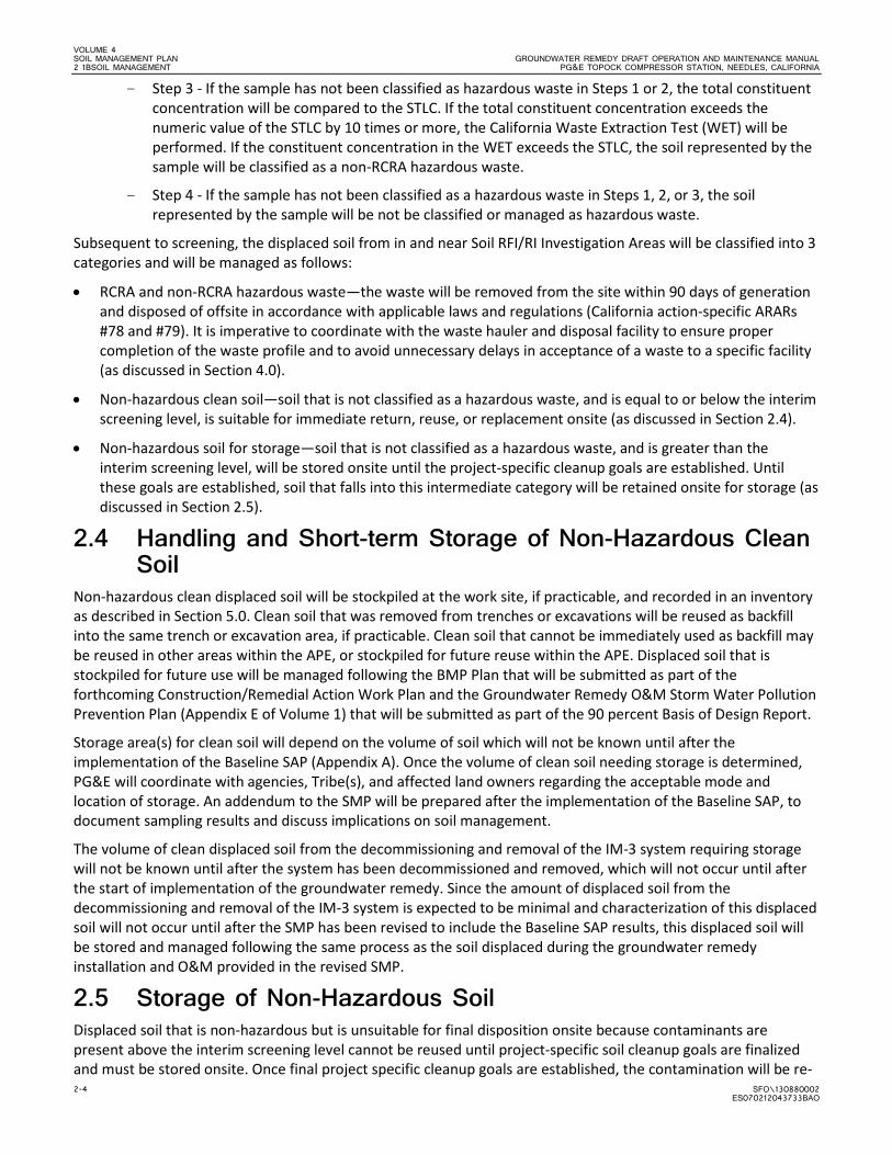
VOLUME 4 SOIL MANAGEMENT PLAN GROUNDWATER REMEDY DRAFT OPERATION AND MAINTENANCE MANUAL 2 1BSOIL MANAGEMENT PG&E TOPOCK COMPRESSOR STATION, NEEDLES, CALIFORNIA
2-4 SFO\130880002 ES070212043733BAO
- Step 3 - If the sample has not been classified as hazardous waste in Steps 1 or 2, the total constituent concentration will be compared to the STLC. If the total constituent concentration exceeds the numeric value of the STLC by 10 times or more, the California Waste Extraction Test (WET) will be performed. If the constituent concentration in the WET exceeds the STLC, the soil represented by the sample will be classified as a non-RCRA hazardous waste.
- Step 4 - If the sample has not been classified as a hazardous waste in Steps 1, 2, or 3, the soil represented by the sample will be not be classified or managed as hazardous waste.
Subsequent to screening, the displaced soil from in and near Soil RFI/RI Investigation Areas will be classified into 3 categories and will be managed as follows:
• RCRA and non-RCRA hazardous waste—the waste will be removed from the site within 90 days of generation and disposed of offsite in accordance with applicable laws and regulations (California action-specific ARARs #78 and #79). It is imperative to coordinate with the waste hauler and disposal facility to ensure proper completion of the waste profile and to avoid unnecessary delays in acceptance of a waste to a specific facility (as discussed in Section 4.0).
• Non-hazardous clean soil—soil that is not classified as a hazardous waste, and is equal to or below the interim screening level, is suitable for immediate return, reuse, or replacement onsite (as discussed in Section 2.4).
• Non-hazardous soil for storage—soil that is not classified as a hazardous waste, and is greater than the interim screening level, will be stored onsite until the project-specific cleanup goals are established. Until these goals are established, soil that falls into this intermediate category will be retained onsite for storage (as discussed in Section 2.5).
2.4 Handling and Short-term Storage of Non-Hazardous Clean Soil
Non-hazardous clean displaced soil will be stockpiled at the work site, if practicable, and recorded in an inventory as described in Section 5.0. Clean soil that was removed from trenches or excavations will be reused as backfill into the same trench or excavation area, if practicable. Clean soil that cannot be immediately used as backfill may be reused in other areas within the APE, or stockpiled for future reuse within the APE. Displaced soil that is stockpiled for future use will be managed following the BMP Plan that will be submitted as part of the forthcoming Construction/Remedial Action Work Plan and the Groundwater Remedy O&M Storm Water Pollution Prevention Plan (Appendix E of Volume 1) that will be submitted as part of the 90 percent Basis of Design Report.
Storage area(s) for clean soil will depend on the volume of soil which will not be known until after the implementation of the Baseline SAP (Appendix A). Once the volume of clean soil needing storage is determined, PG&E will coordinate with agencies, Tribe(s), and affected land owners regarding the acceptable mode and location of storage. An addendum to the SMP will be prepared after the implementation of the Baseline SAP, to document sampling results and discuss implications on soil management.
The volume of clean displaced soil from the decommissioning and removal of the IM-3 system requiring storage will not be known until after the system has been decommissioned and removed, which will not occur until after the start of implementation of the groundwater remedy. Since the amount of displaced soil from the decommissioning and removal of the IM-3 system is expected to be minimal and characterization of this displaced soil will not occur until after the SMP has been revised to include the Baseline SAP results, this displaced soil will be stored and managed following the same process as the soil displaced during the groundwater remedy installation and O&M provided in the revised SMP.
2.5 Storage of Non-Hazardous Soil Displaced soil that is non-hazardous but is unsuitable for final disposition onsite because contaminants are present above the interim screening level cannot be reused until project-specific soil cleanup goals are finalized and must be stored onsite. Once final project specific cleanup goals are established, the contamination will be re-
VOLUME 4 GROUNDWATER REMEDY DRAFT OPERATION AND MAINTENANCE MANUAL SOIL MANAGEMENT PLAN PG&E TOPOCK COMPRESSOR STATION, NEEDLES, CALIFORNIA 2 1BSOIL MANAGEMENT
SFO\130880002 2-5 ES070212043733BAO
assessed based on existing data, or additional data as determined necessary, to determine final disposition (i.e., transportation to offsite disposal facility or reuse within the APE).
Storage area(s) will depend on the volume of soil, which will not be known until after the implementation of the Baseline SAP (Appendix A). Once the volume of soil needing storage is determined, PG&E will coordinate with agencies, Tribe(s), and affected land owners regarding the acceptable mode and location of storage. An addendum to the SMP will be prepared after the implementation of the Baseline SAP to document sampling results and discuss implications on soil management and storage of soil.
The volume of displaced soil in and near Soil RFI/RI Areas from the decommissioning and removal of the IM-3 system requiring storage will not be known until after the system has been decommissioned and removed, which will be after the start of implementation of the groundwater remedy. Since the amount of displaced soil in and near Soil RFI/RI Areas from the decommissioning and removal of the IM-3 system is expected to be minimal and characterization of this displaced soil will not occur until after the SMP has been revised to include the Baseline SAP results, this displaced soil will be stored and managed following the same process as the soil displaced during the groundwater remedy installation and O&M provided in the revised SMP.

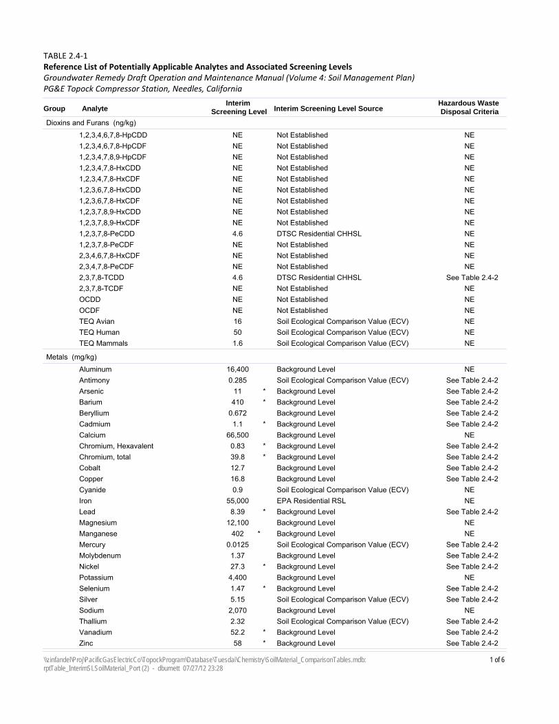
Interim Screening Level SourceInterim
Screening LevelAnalyteGroup
TABLE 2.4‐1Reference List of Potentially Applicable Analytes and Associated Screening Levels
PG&E Topock Compressor Station, Needles, California
Hazardous Waste Disposal Criteria
Groundwater Remedy Draft Operation and Maintenance Manual (Volume 4: Soil Management Plan)
Dioxins and Furans (ng/kg)
Not EstablishedNE1,2,3,4,6,7,8-HpCDD NENot EstablishedNE1,2,3,4,6,7,8-HpCDF NENot EstablishedNE1,2,3,4,7,8,9-HpCDF NENot EstablishedNE1,2,3,4,7,8-HxCDD NENot EstablishedNE1,2,3,4,7,8-HxCDF NENot EstablishedNE1,2,3,6,7,8-HxCDD NENot EstablishedNE1,2,3,6,7,8-HxCDF NENot EstablishedNE1,2,3,7,8,9-HxCDD NENot EstablishedNE1,2,3,7,8,9-HxCDF NEDTSC Residential CHHSL4.61,2,3,7,8-PeCDD NENot EstablishedNE1,2,3,7,8-PeCDF NENot EstablishedNE2,3,4,6,7,8-HxCDF NENot EstablishedNE2,3,4,7,8-PeCDF NEDTSC Residential CHHSL4.62,3,7,8-TCDD See Table 2.4-2Not EstablishedNE2,3,7,8-TCDF NENot EstablishedNEOCDD NENot EstablishedNEOCDF NESoil Ecological Comparison Value (ECV)16TEQ Avian NESoil Ecological Comparison Value (ECV)50TEQ Human NESoil Ecological Comparison Value (ECV)1.6TEQ Mammals NE
Metals (mg/kg)
Background Level16,400Aluminum NESoil Ecological Comparison Value (ECV)0.285Antimony See Table 2.4-2Background Level11Arsenic See Table 2.4-2*Background Level410Barium See Table 2.4-2*Background Level0.672Beryllium See Table 2.4-2Background Level1.1Cadmium See Table 2.4-2*Background Level66,500Calcium NEBackground Level0.83Chromium, Hexavalent See Table 2.4-2*Background Level39.8Chromium, total See Table 2.4-2*Background Level12.7Cobalt See Table 2.4-2Background Level16.8Copper See Table 2.4-2Soil Ecological Comparison Value (ECV)0.9Cyanide NEEPA Residential RSL55,000Iron NEBackground Level8.39Lead See Table 2.4-2*Background Level12,100Magnesium NEBackground Level402Manganese NE*Soil Ecological Comparison Value (ECV)0.0125Mercury See Table 2.4-2Background Level1.37Molybdenum See Table 2.4-2Background Level27.3Nickel See Table 2.4-2*Background Level4,400Potassium NEBackground Level1.47Selenium See Table 2.4-2*Soil Ecological Comparison Value (ECV)5.15Silver See Table 2.4-2Background Level2,070Sodium NESoil Ecological Comparison Value (ECV)2.32Thallium See Table 2.4-2Background Level52.2Vanadium See Table 2.4-2*Background Level58Zinc See Table 2.4-2*
1 of 6\\zinfandel\Proj\PacificGasElectricCo\TopockProgram\Database\Tuesdai\Chemistry\SoilMaterial_ComparisonTables.mdb: rptTable_InterimSLSoilMaterial_Port (2) - dburnett 07/27/12 23:28
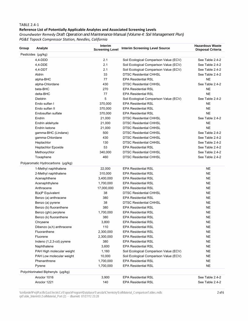
Interim Screening Level SourceInterim
Screening LevelAnalyteGroup
TABLE 2.4‐1Reference List of Potentially Applicable Analytes and Associated Screening Levels
PG&E Topock Compressor Station, Needles, California
Hazardous Waste Disposal Criteria
Groundwater Remedy Draft Operation and Maintenance Manual (Volume 4: Soil Management Plan)
Pesticides (µg/kg)
Soil Ecological Comparison Value (ECV)2.14,4-DDD See Table 2.4-2Soil Ecological Comparison Value (ECV)2.14,4-DDE See Table 2.4-2Soil Ecological Comparison Value (ECV)2.14,4-DDT See Table 2.4-2DTSC Residential CHHSL33Aldrin See Table 2.4-2EPA Residential RSL77alpha-BHC NEDTSC Residential CHHSL430alpha-Chlordane See Table 2.4-2EPA Residential RSL270beta-BHC NEEPA Residential RSL77delta-BHC NESoil Ecological Comparison Value (ECV)5Dieldrin See Table 2.4-2EPA Residential RSL370,000Endo sulfan I NEEPA Residential RSL370,000Endo sulfan II NEEPA Residential RSL370,000Endosulfan sulfate NEDTSC Residential CHHSL21,000Endrin See Table 2.4-2DTSC Residential CHHSL21,000Endrin aldehyde NEDTSC Residential CHHSL21,000Endrin ketone NEDTSC Residential CHHSL500gamma-BHC (Lindane) See Table 2.4-2DTSC Residential CHHSL430gamma-Chlordane See Table 2.4-2DTSC Residential CHHSL130Heptachlor See Table 2.4-2EPA Residential RSL53Heptachlor Epoxide See Table 2.4-2DTSC Residential CHHSL340,000Methoxychlor See Table 2.4-2DTSC Residential CHHSL460Toxaphene See Table 2.4-2
Polyaromatic Hydrocarbons (µg/kg)
EPA Residential RSL22,0001-Methyl naphthalene NEEPA Residential RSL310,0002-Methyl naphthalene NEEPA Residential RSL3,400,000Acenaphthene NEEPA Residential RSL1,700,000Acenaphthylene NEEPA Residential RSL17,000,000Anthracene NEDTSC Residential CHHSL38B(a)P Equivalent NEEPA Residential RSL380Benzo (a) anthracene NEDTSC Residential CHHSL38Benzo (a) pyrene NEEPA Residential RSL380Benzo (b) fluoranthene NEEPA Residential RSL1,700,000Benzo (ghi) perylene NEEPA Residential RSL380Benzo (k) fluoranthene NEEPA Residential RSL3,800Chrysene NEEPA Residential RSL110Dibenzo (a,h) anthracene NEEPA Residential RSL2,300,000Fluoranthene NEEPA Residential RSL2,300,000Fluorene NEEPA Residential RSL380Indeno (1,2,3-cd) pyrene NEEPA Residential RSL3,600Naphthalene NESoil Ecological Comparison Value (ECV)1,160PAH High molecular weight NESoil Ecological Comparison Value (ECV)10,000PAH Low molecular weight NEEPA Residential RSL1,700,000Phenanthrene NEEPA Residential RSL1,700,000Pyrene NE
Polychlorinated Biphenyls (µg/kg)
EPA Residential RSL3,900Aroclor 1016 See Table 2.4-2EPA Residential RSL140Aroclor 1221 See Table 2.4-2
2 of 6\\zinfandel\Proj\PacificGasElectricCo\TopockProgram\Database\Tuesdai\Chemistry\SoilMaterial_ComparisonTables.mdb: rptTable_InterimSLSoilMaterial_Port (2) - dburnett 07/27/12 23:28
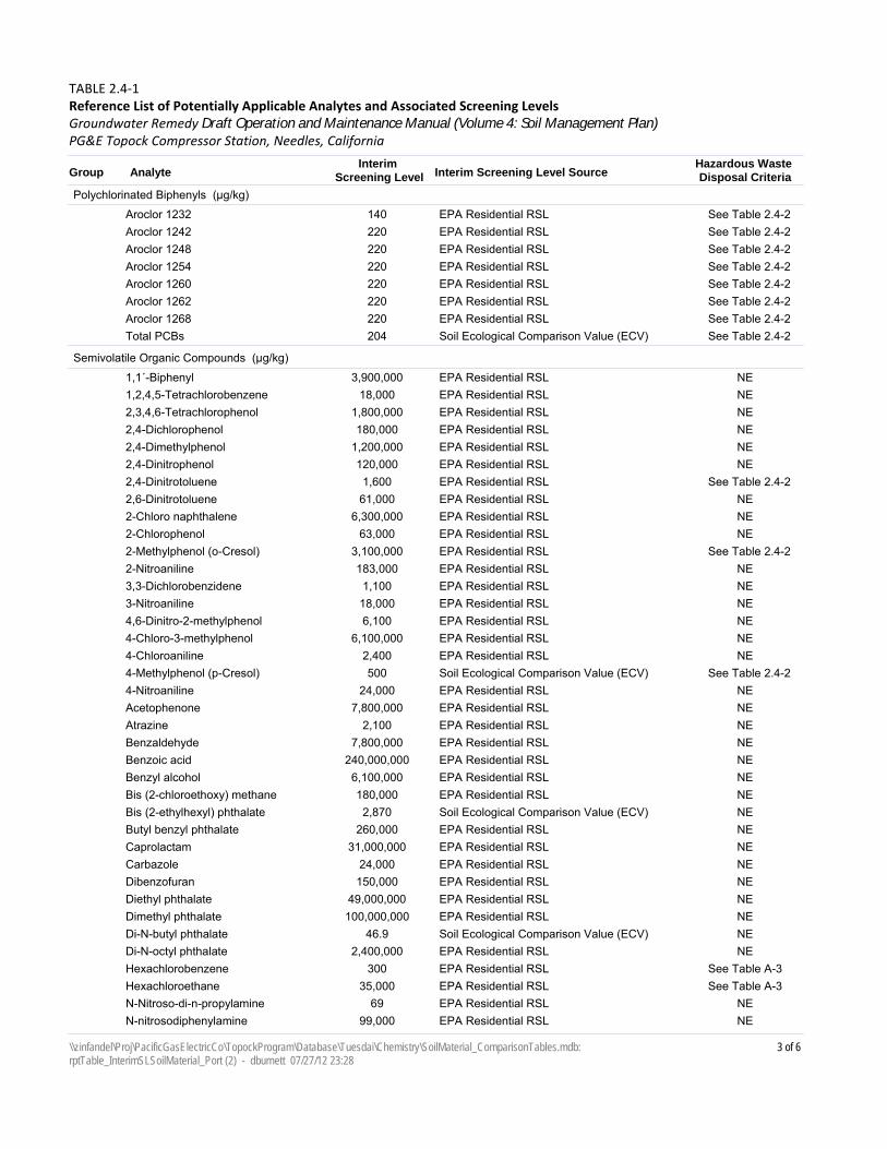
Interim Screening Level SourceInterim
Screening LevelAnalyteGroup
TABLE 2.4‐1Reference List of Potentially Applicable Analytes and Associated Screening Levels
PG&E Topock Compressor Station, Needles, California
Hazardous Waste Disposal Criteria
Groundwater Remedy Draft Operation and Maintenance Manual (Volume 4: Soil Management Plan)
Polychlorinated Biphenyls (µg/kg)
EPA Residential RSL140Aroclor 1232 See Table 2.4-2EPA Residential RSL220Aroclor 1242 See Table 2.4-2EPA Residential RSL220Aroclor 1248 See Table 2.4-2EPA Residential RSL220Aroclor 1254 See Table 2.4-2EPA Residential RSL220Aroclor 1260 See Table 2.4-2EPA Residential RSL220Aroclor 1262 See Table 2.4-2EPA Residential RSL220Aroclor 1268 See Table 2.4-2Soil Ecological Comparison Value (ECV)204Total PCBs See Table 2.4-2
Semivolatile Organic Compounds (µg/kg)
EPA Residential RSL3,900,0001,1´-Biphenyl NEEPA Residential RSL18,0001,2,4,5-Tetrachlorobenzene NEEPA Residential RSL1,800,0002,3,4,6-Tetrachlorophenol NEEPA Residential RSL180,0002,4-Dichlorophenol NEEPA Residential RSL1,200,0002,4-Dimethylphenol NEEPA Residential RSL120,0002,4-Dinitrophenol NEEPA Residential RSL1,6002,4-Dinitrotoluene See Table 2.4-2EPA Residential RSL61,0002,6-Dinitrotoluene NEEPA Residential RSL6,300,0002-Chloro naphthalene NEEPA Residential RSL63,0002-Chlorophenol NEEPA Residential RSL3,100,0002-Methylphenol (o-Cresol) See Table 2.4-2EPA Residential RSL183,0002-Nitroaniline NEEPA Residential RSL1,1003,3-Dichlorobenzidene NEEPA Residential RSL18,0003-Nitroaniline NEEPA Residential RSL6,1004,6-Dinitro-2-methylphenol NEEPA Residential RSL6,100,0004-Chloro-3-methylphenol NEEPA Residential RSL2,4004-Chloroaniline NESoil Ecological Comparison Value (ECV)5004-Methylphenol (p-Cresol) See Table 2.4-2EPA Residential RSL24,0004-Nitroaniline NEEPA Residential RSL7,800,000Acetophenone NEEPA Residential RSL2,100Atrazine NEEPA Residential RSL7,800,000Benzaldehyde NEEPA Residential RSL240,000,000Benzoic acid NEEPA Residential RSL6,100,000Benzyl alcohol NEEPA Residential RSL180,000Bis (2-chloroethoxy) methane NESoil Ecological Comparison Value (ECV)2,870Bis (2-ethylhexyl) phthalate NEEPA Residential RSL260,000Butyl benzyl phthalate NEEPA Residential RSL31,000,000Caprolactam NEEPA Residential RSL24,000Carbazole NEEPA Residential RSL150,000Dibenzofuran NEEPA Residential RSL49,000,000Diethyl phthalate NEEPA Residential RSL100,000,000Dimethyl phthalate NESoil Ecological Comparison Value (ECV)46.9Di-N-butyl phthalate NEEPA Residential RSL2,400,000Di-N-octyl phthalate NEEPA Residential RSL300Hexachlorobenzene See Table A-3EPA Residential RSL35,000Hexachloroethane See Table A-3EPA Residential RSL69N-Nitroso-di-n-propylamine NEEPA Residential RSL99,000N-nitrosodiphenylamine NE
3 of 6\\zinfandel\Proj\PacificGasElectricCo\TopockProgram\Database\Tuesdai\Chemistry\SoilMaterial_ComparisonTables.mdb: rptTable_InterimSLSoilMaterial_Port (2) - dburnett 07/27/12 23:28
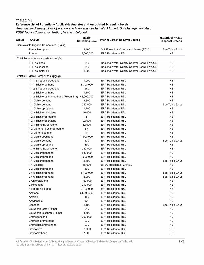
Interim Screening Level SourceInterim
Screening LevelAnalyteGroup
TABLE 2.4‐1Reference List of Potentially Applicable Analytes and Associated Screening Levels
PG&E Topock Compressor Station, Needles, California
Hazardous Waste Disposal Criteria
Groundwater Remedy Draft Operation and Maintenance Manual (Volume 4: Soil Management Plan)
Semivolatile Organic Compounds (µg/kg)
Soil Ecological Comparison Value (ECV)2,490Pentachlorophenol See Table 2.4-2EPA Residential RSL18,000,000Phenol NE
Total Petroleum Hydrocarbons (mg/kg)
Regional Water Quality Control Board (RWQCB)540TPH as diesel NERegional Water Quality Control Board (RWQCB)540TPH as gasoline NERegional Water Quality Control Board (RWQCB)1,800TPH as motor oil NE
Volatile Organic Compounds (µg/kg)
EPA Residential RSL1,9001,1,1,2-Tetrachloroethane NEEPA Residential RSL8,700,0001,1,1-Trichloroethane NEEPA Residential RSL5601,1,2,2-Tetrachloroethane NEEPA Residential RSL1,1001,1,2-Trichloroethane NEEPA Residential RSL43,000,0001,1,2-Trichlorotrifluoroethane (Freon 113) NEEPA Residential RSL3,3001,1-Dichloroethane NEEPA Residential RSL240,0001,1-Dichloroethene See Table 2.4-2EPA Residential RSL1,7001,1-Dichloropropene NEEPA Residential RSL49,0001,2,3-Trichlorobenzene NEEPA Residential RSL51,2,3-Trichloropropane NEEPA Residential RSL22,0001,2,4-Trichlorobenzene NEEPA Residential RSL62,0001,2,4-Trimethylbenzene NEEPA Residential RSL5.41,2-Dibromo-3-chloropropane NEEPA Residential RSL341,2-Dibromoethane NEEPA Residential RSL1,900,0001,2-Dichlorobenzene NEEPA Residential RSL4301,2-Dichloroethane See Table 2.4-2EPA Residential RSL8901,2-Dichloropropane NEEPA Residential RSL780,0001,3,5-Trimethylbenzene NEEPA Residential RSL530,0001,3-Dichlorobenzene NEEPA Residential RSL1,600,0001,3-Dichloropropane NEEPA Residential RSL2,4001,4-Dichlorobenzene See Table 2.4-2DTSC Residential CHHSL18,0001,4-Dioxane NEEPA Residential RSL8902,2-Dichloropropane NEEPA Residential RSL6,100,0002,4,5-Trichlorophenol See Table 2.4-2EPA Residential RSL6,9002,4,6-Trichlorophenol See Table 2.4-2EPA Residential RSL160,0002-Chlorotoluene NEEPA Residential RSL210,0002-Hexanone NEEPA Residential RSL2,100,0004-Isopropyltoluene NEEPA Residential RSL61,000,000Acetone NEEPA Residential RSL150Acrolein NEEPA Residential RSL55Acrylonitrile NEEPA Residential RSL1,100Benzene See Table 2.4-2EPA Residential RSL210Bis (2-chloroethyl) ether NEEPA Residential RSL4,600Bis (2-chloroisopropyl) ether NEEPA Residential RSL300,000Bromobenzene NEEPA Residential RSL270Bromochloromethane NEEPA Residential RSL270Bromodichloromethane NEEPA Residential RSL61,000Bromoform NEEPA Residential RSL7,300Bromomethane NE
4 of 6\\zinfandel\Proj\PacificGasElectricCo\TopockProgram\Database\Tuesdai\Chemistry\SoilMaterial_ComparisonTables.mdb: rptTable_InterimSLSoilMaterial_Port (2) - dburnett 07/27/12 23:28
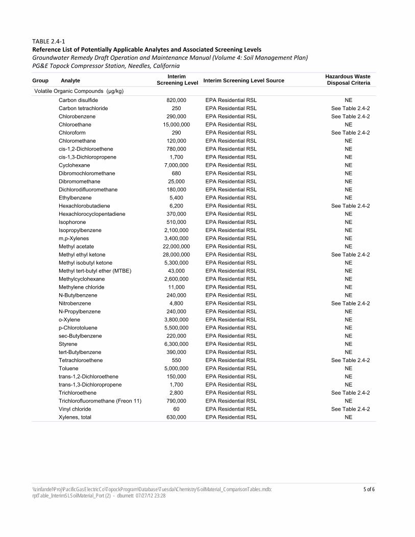
Interim Screening Level SourceInterim
Screening LevelAnalyteGroup
TABLE 2.4‐1Reference List of Potentially Applicable Analytes and Associated Screening Levels
PG&E Topock Compressor Station, Needles, California
Hazardous Waste Disposal Criteria
Groundwater Remedy Draft Operation and Maintenance Manual (Volume 4: Soil Management Plan)
Volatile Organic Compounds (µg/kg)
EPA Residential RSL820,000Carbon disulfide NEEPA Residential RSL250Carbon tetrachloride See Table 2.4-2EPA Residential RSL290,000Chlorobenzene See Table 2.4-2EPA Residential RSL15,000,000Chloroethane NEEPA Residential RSL290Chloroform See Table 2.4-2EPA Residential RSL120,000Chloromethane NEEPA Residential RSL780,000cis-1,2-Dichloroethene NEEPA Residential RSL1,700cis-1,3-Dichloropropene NEEPA Residential RSL7,000,000Cyclohexane NEEPA Residential RSL680Dibromochloromethane NEEPA Residential RSL25,000Dibromomethane NEEPA Residential RSL180,000Dichlorodifluoromethane NEEPA Residential RSL5,400Ethylbenzene NEEPA Residential RSL6,200Hexachlorobutadiene See Table 2.4-2EPA Residential RSL370,000Hexachlorocyclopentadiene NEEPA Residential RSL510,000Isophorone NEEPA Residential RSL2,100,000Isopropylbenzene NEEPA Residential RSL3,400,000m,p-Xylenes NEEPA Residential RSL22,000,000Methyl acetate NEEPA Residential RSL28,000,000Methyl ethyl ketone See Table 2.4-2EPA Residential RSL5,300,000Methyl isobutyl ketone NEEPA Residential RSL43,000Methyl tert-butyl ether (MTBE) NEEPA Residential RSL2,600,000Methylcyclohexane NEEPA Residential RSL11,000Methylene chloride NEEPA Residential RSL240,000N-Butylbenzene NEEPA Residential RSL4,800Nitrobenzene See Table 2.4-2EPA Residential RSL240,000N-Propylbenzene NEEPA Residential RSL3,800,000o-Xylene NEEPA Residential RSL5,500,000p-Chlorotoluene NEEPA Residential RSL220,000sec-Butylbenzene NEEPA Residential RSL6,300,000Styrene NEEPA Residential RSL390,000tert-Butylbenzene NEEPA Residential RSL550Tetrachloroethene See Table 2.4-2EPA Residential RSL5,000,000Toluene NEEPA Residential RSL150,000trans-1,2-Dichloroethene NEEPA Residential RSL1,700trans-1,3-Dichloropropene NEEPA Residential RSL2,800Trichloroethene See Table 2.4-2EPA Residential RSL790,000Trichlorofluoromethane (Freon 11) NEEPA Residential RSL60Vinyl chloride See Table 2.4-2EPA Residential RSL630,000Xylenes, total NE
5 of 6\\zinfandel\Proj\PacificGasElectricCo\TopockProgram\Database\Tuesdai\Chemistry\SoilMaterial_ComparisonTables.mdb: rptTable_InterimSLSoilMaterial_Port (2) - dburnett 07/27/12 23:28

Notes:
California Department of Toxic Substances Control; California human health screening levels (OEHHA, 2005)
milligrams per kilogram
DTSC CHHSL
mg/kg
Interim screening level is background value. If background value is not available then the lesser of the DTSC residential CHHSL or the ecological comparison value is used. If CHHSL is not available, it is the lesser of the USEPA residential regional screening level or the ecological comparison value.
Background "Final Soil Background Investigation at Pacific Gas and Electric Company Topock Compressor Station, Needles, California" (CH2M HIll, May 2009)
United States Environmental Protection Agency Regional Screening Level, various dates. See Tables 3-1 to 3-8 of the Soil Investigation Part A Phase 1 Data Gaps Evaluation Report (CH2M HILL, 5/2011) for respective dates for each RSL.
EPA RSL
micrograms per kilogramµg/kg
Ecological Comparison Values; ECV were calculated as needed for constituents detected during the Part APhase I sampling (Arcadis, 2008)
ECV
"San Francisco Bay Regional Water Quality Control Board Environmental Screening Levels, Screening For Environmental Concerns at Sites With Contaminated Soil and Groundwater" (Table K-1). May 27, 2008
RWQCB
nanograms per kilogramng/kg
This table presents a reference list of analytes and associated screening levels that may be applicable for making decisions related to disposition of displaced site materials. The specific analytes and screening levels applicable for characterization of displaced material will be determined based on the origin of the material and potential disposition locations.
not establishedNEOne or more screening levels (EPA RSL, DTSC CHHSL, ECV, or Soil SL) have values lower than the background level.*
6 of 6\\zinfandel\Proj\PacificGasElectricCo\TopockProgram\Database\Tuesdai\Chemistry\SoilMaterial_ComparisonTables.mdb: rptTable_InterimSLSoilMaterial_Port (2) - dburnett 07/27/12 23:28
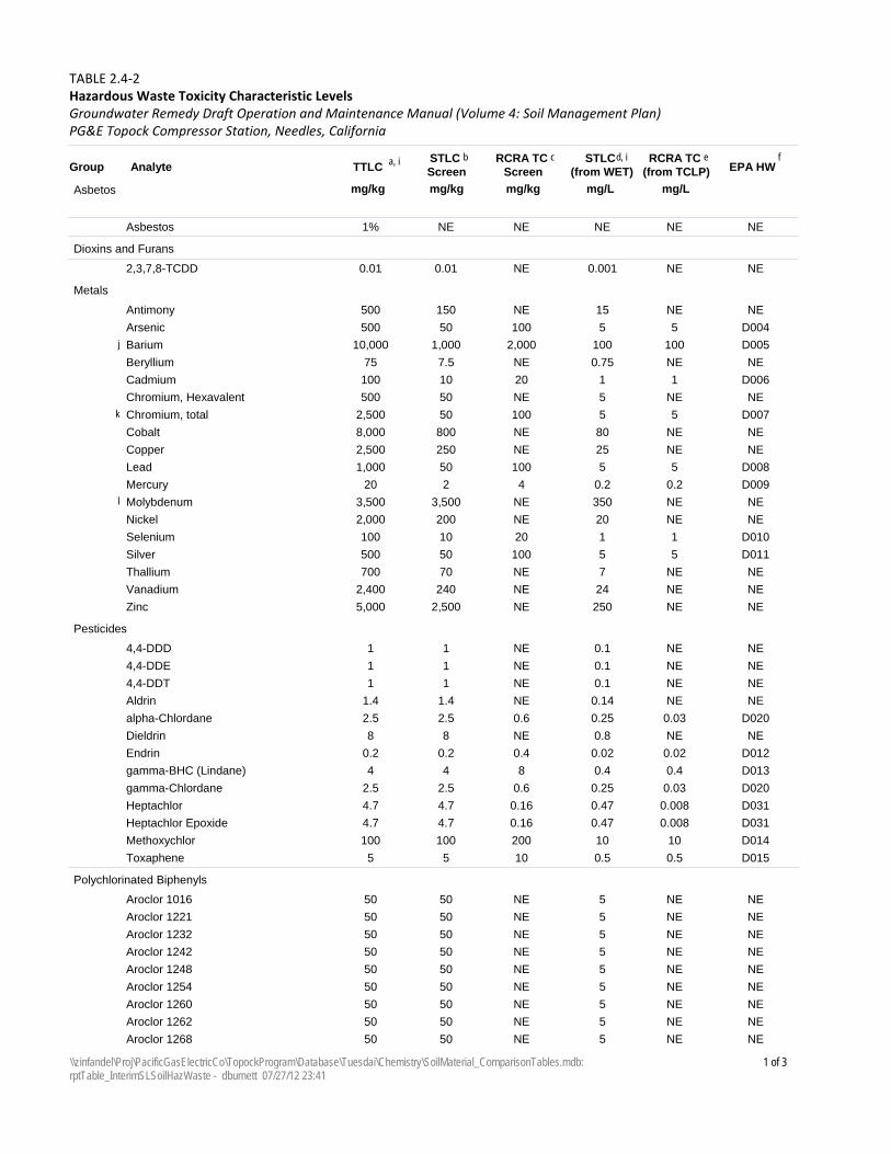
TTLCAnalyteGroupSTLC Screen
RCRA TC Screen
STLC (from WET)
RCRA TC (from TCLP)
mg/kg mg/kg mg/kg mg/L mg/L
a, i b d, ic eEPA HW
f
TABLE 2.4‐2Hazardous Waste Toxicity Characteristic Levels
PG&E Topock Compressor Station, Needles, CaliforniaGroundwater Remedy Draft Operation and Maintenance Manual (Volume 4: Soil Management Plan)
Asbetos
1%Asbestos NE NE NE NE NE
Dioxins and Furans
0.012,3,7,8-TCDD 0.01 NE 0.001 NE NE
Metals
500Antimony 150 NE 15 NE NE
500Arsenic 50 100 5 5 D004
10,000Barium 1,000 2,000 100 100j D005
75Beryllium 7.5 NE 0.75 NE NE
100Cadmium 10 20 1 1 D006
500Chromium, Hexavalent 50 NE 5 NE NE
2,500Chromium, total 50 100 5 5k D007
8,000Cobalt 800 NE 80 NE NE
2,500Copper 250 NE 25 NE NE
1,000Lead 50 100 5 5 D008
20Mercury 2 4 0.2 0.2 D009
3,500Molybdenum 3,500 NE 350 NEl NE
2,000Nickel 200 NE 20 NE NE
100Selenium 10 20 1 1 D010
500Silver 50 100 5 5 D011
700Thallium 70 NE 7 NE NE
2,400Vanadium 240 NE 24 NE NE
5,000Zinc 2,500 NE 250 NE NE
Pesticides
14,4-DDD 1 NE 0.1 NE NE
14,4-DDE 1 NE 0.1 NE NE
14,4-DDT 1 NE 0.1 NE NE
1.4Aldrin 1.4 NE 0.14 NE NE
2.5alpha-Chlordane 2.5 0.6 0.25 0.03 D020
8Dieldrin 8 NE 0.8 NE NE
0.2Endrin 0.2 0.4 0.02 0.02 D012
4gamma-BHC (Lindane) 4 8 0.4 0.4 D013
2.5gamma-Chlordane 2.5 0.6 0.25 0.03 D020
4.7Heptachlor 4.7 0.16 0.47 0.008 D031
4.7Heptachlor Epoxide 4.7 0.16 0.47 0.008 D031
100Methoxychlor 100 200 10 10 D014
5Toxaphene 5 10 0.5 0.5 D015
Polychlorinated Biphenyls
50Aroclor 1016 50 NE 5 NE NE
50Aroclor 1221 50 NE 5 NE NE
50Aroclor 1232 50 NE 5 NE NE
50Aroclor 1242 50 NE 5 NE NE
50Aroclor 1248 50 NE 5 NE NE
50Aroclor 1254 50 NE 5 NE NE
50Aroclor 1260 50 NE 5 NE NE
50Aroclor 1262 50 NE 5 NE NE
50Aroclor 1268 50 NE 5 NE NE
1 of 3\\zinfandel\Proj\PacificGasElectricCo\TopockProgram\Database\Tuesdai\Chemistry\SoilMaterial_ComparisonTables.mdb: rptTable_InterimSLSoilHazWaste - dburnett 07/27/12 23:41
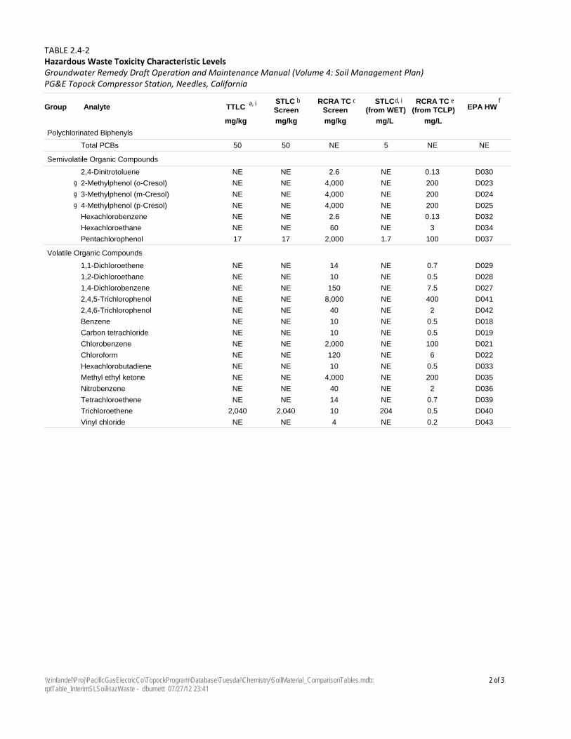
TTLCAnalyteGroupSTLC Screen
RCRA TC Screen
STLC (from WET)
RCRA TC (from TCLP)
mg/kg mg/kg mg/kg mg/L mg/L
a, i b d, ic eEPA HW
f
TABLE 2.4‐2Hazardous Waste Toxicity Characteristic Levels
PG&E Topock Compressor Station, Needles, CaliforniaGroundwater Remedy Draft Operation and Maintenance Manual (Volume 4: Soil Management Plan)
Polychlorinated Biphenyls
50Total PCBs 50 NE 5 NE NE
Semivolatile Organic Compounds
NE2,4-Dinitrotoluene NE 2.6 NE 0.13 D030
NE2-Methylphenol (o-Cresol) NE 4,000 NE 200g D023
NE3-Methylphenol (m-Cresol) NE 4,000 NE 200g D024
NE4-Methylphenol (p-Cresol) NE 4,000 NE 200g D025
NEHexachlorobenzene NE 2.6 NE 0.13 D032
NEHexachloroethane NE 60 NE 3 D034
17Pentachlorophenol 17 2,000 1.7 100 D037
Volatile Organic Compounds
NE1,1-Dichloroethene NE 14 NE 0.7 D029
NE1,2-Dichloroethane NE 10 NE 0.5 D028
NE1,4-Dichlorobenzene NE 150 NE 7.5 D027
NE2,4,5-Trichlorophenol NE 8,000 NE 400 D041
NE2,4,6-Trichlorophenol NE 40 NE 2 D042
NEBenzene NE 10 NE 0.5 D018
NECarbon tetrachloride NE 10 NE 0.5 D019
NEChlorobenzene NE 2,000 NE 100 D021
NEChloroform NE 120 NE 6 D022
NEHexachlorobutadiene NE 10 NE 0.5 D033
NEMethyl ethyl ketone NE 4,000 NE 200 D035
NENitrobenzene NE 40 NE 2 D036
NETetrachloroethene NE 14 NE 0.7 D039
2,040Trichloroethene 2,040 10 204 0.5 D040
NEVinyl chloride NE 4 NE 0.2 D043
2 of 3\\zinfandel\Proj\PacificGasElectricCo\TopockProgram\Database\Tuesdai\Chemistry\SoilMaterial_ComparisonTables.mdb: rptTable_InterimSLSoilHazWaste - dburnett 07/27/12 23:41
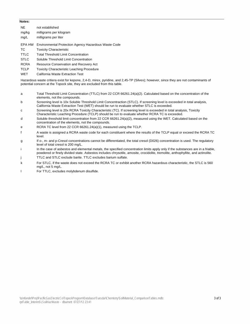
Notes:
milligrams per kilogrammg/kg
milligrams per litermg/L
not establishedNE
Total Threshold Limit ConcentrationTTLC
Soluble Threshold Limit ConcentrationSTLC
Toxicity Characteristic Leaching ProcedureTCLP
Resource Conservation and Recovery ActRCRA
Toxicity CharacteristicTC
California Waste Extraction TestWET
Environmental Protection Agency Hazardous Waste CodeEPA HW
Hazardous waste critiera exist for kepone, 2,4-D, mirex, pyridine, and 2,45-TP (Silvex); however, since they are not contaminants of potential concern at the Topock site, they are excluded from this table.
Total Threshold Limit Concentration (TTLC) from 22 CCR 66261.24(a)(2). Calculated based on the concentration of the elements, not the compounds.
a
Screening level is 10x Soluble Threshold Limit Concentraction (STLC). If screening level is exceeded in total analysis, California Waste Extraction Test (WET) should be run to evaluate whether STLC is exceeded.
b
Screening level is 20x RCRA Toxicity Characteristic (TC). If screening level is exceeded in total analysis, Toxicity Characteristic Leaching Procedure (TCLP) should be run to evaluate whether RCRA TC is exceeded.
c
Soluble threshold limit concentration from 22 CCR 66261.24(a)(2), measured using the WET. Calculated based on the concentration of the elements, not the compounds.
d
RCRA TC level from 22 CCR 66261.24(a)(1), measured using the TCLP.e
A waste is assigned a RCRA waste code for each constituent where the results of the TCLP equal or exceed the RCRA TC level.
f
If o-, m- and p-Cresol concentrations cannot be differentiated, the total cresol (D026) concentration is used. The regulatory level of total cresol is 200 mg/L.
g
In the case of asbestos and elemental metals, the specified concentration limits apply only if the substances are in a friable, powdered or finely divided state. Asbestos includes chrysotile, amosite, crocidolite, tremolite, anthophyllite, and actinolite.
i
TTLC and STLC exclude barite. TTLC excludes barium sulfate.j
For STLC, if the waste does not exceed the RCRA TC or exhibit another RCRA hazardous characteristic, the STLC is 560 mg/L, not 5 mg/L.
k
For TTLC, excludes molybdenum disulfide.l
3 of 3\\zinfandel\Proj\PacificGasElectricCo\TopockProgram\Database\Tuesdai\Chemistry\SoilMaterial_ComparisonTables.mdb: rptTable_InterimSLSoilHazWaste - dburnett 07/27/12 23:41

SFO\130880002 3-1 ES070212043733BAO
SECTION 3
Soil Storage This section describes the storage procedures for soil displaced in or near Soil RFI/RI Investigation Areas during drilling, construction, decommissioning, removal, and O&M activities at the site. Displaced soil will be segregated into the following waste streams:
• RCRA Hazardous Waste
• Non-RCRA Hazardous Waste
• Non-hazardous Waste − Clean soil − Soil for storage until project cleanup goals are defined.
Soil that is classified as non-hazardous waste clean soil that is suitable for final deposition onsite will be managed following the BMP Plan that will be submitted as part of the forthcoming Construction/Remedial Action Work Plan and the Groundwater Remedy O&M Storm Water Pollution Prevention Plan (Appendix E of Volume 1) that will be submitted as part of the 90% Basis of Design Report.
This section only applies to Non-RCRA and RCRA Hazardous Waste and non-hazardous waste soil above interim screening levels that will require storage until project cleanup goals are defined. The procedures for accumulation of hazardous waste onsite shall be in compliance with California action-specific ARAR #79 (22 CCR 66262.34). In addition, containerization of hazardous waste shall be in compliance with ARAR #84 (22 CCR, Div 4.5, Ch 14, Article 9), ARAR #85 (22 CCR, Div 4.5, Ch 14, Article 10) and for RCRA hazardous waste, ARAR #86 (22 CCR Div 4.5, Ch 14, Article 12).
3.1 Methods to Store Soil Soil will be stored in 55-gallon drums/small containers, roll-off bins, and/or stockpiles. Soil that is classified as hazardous waste and placed in containers must comply with Title 22 CCR Div. 4.5, Chapter 15, Article 9 (container management), Article 27, Article 28 and Article 28.5 (air emission standards) as required by ARAR #79, and with 22 CCR Div. 4.5, Chapter 14, Article 9 (container management) as required by ARAR #84. BMPs for each method of soil storage are described below; these BMPs must be followed to comply with mandatory regulatory requirements.
3.1.1 Drums/Small Containers Drums containing soils which are hazardous waste will be stored in a hazardous waste storage area and disposed of within 90 days of generation. Drums/small containers that contain displaced soil from in or near Soil RFI/RI Investigation Areas that is non-hazardous, but unsuitable for final disposition onsite because contaminants are present above the interim screening level will be stored following these BMPs:
• Only DOT-specification containers will be used for soil accumulation.
• Empty drums will be inspected and inventoried upon arrival onsite for signs of contamination and/or deterioration.
• Drums and small containers will be transported to the temporary accumulation areas on wood pallets and will be secured together with non-metallic banding.
• Drums will be placed within a bermed and lined area or otherwise will be provided with secondary containment.
• Adequate aisle space (e.g., 36 inches) will be provided for containers such as 55-gallon drums to allow the unobstructed movement of personnel and equipment for inspection purposes. Drums will be placed with no more than two drums per row. The column length must fit within the lined, bermed area.
VOLUME 4 SOIL MANAGEMENT PLAN GROUNDWATER REMEDY DRAFT OPERATION AND MAINTENANCE MANUAL 3 2BSOIL STORAGE PG&E TOPOCK COMPRESSOR STATION, NEEDLES, CALIFORNIA
3-2 SFO\130880002 ES070212043733BAO
• Each drum will be provided with its own label, and labels will be visible for inspection purposes.
• Drums will remain closed except when removing or adding soil to the drum. Closed means that the lid and securing ring must be on and securely tightened.
• Drums will be disposed of with the contents. If the contents are removed from the drums for offsite transportation and treatment or disposal, the drums will be reused only for compatible soil and waste streams.
3.1.2 Stockpiles RCRA and non-RCRA Hazardous Soil. If it is necessary to temporarily stockpile soil classified as RCRA or non-RCRA hazardous waste for up to 90 days to facilitate characterization or staging for offsite transportation, the liner shall consist of a single sheet of material, or multiple sheets with seams that are sealed together. Hazardous waste stockpiles shall use a minimum 20-mil liner if constructed on a foundation (e.g., pavement or compacted soil) or a 60-mil liner if constructed in a location without a foundation (e.g., unpaved, uncompacted soil). Stockpiles will be inspected by a California-registered professional engineer to verify conformance with these requirements. Temporary staging for up to 90 days prior to offsite transportation will not trigger compliance with ARAR #86 (requirements for waste piles that are applicable to RCRA hazardous waste). The contents of the stockpile, including the words “Hazardous Waste” and the accumulation start date, will be posted on a sign next to the stockpile, and the contents and accumulation start date will be entered in the field logbook. Stockpiles will be inspected on a weekly basis to verify that controls to prevent run-on, runoff, and windblown dispersal of soil are in place and effective. Security and emergency response equipment will be provided as described in Section 3.5.
Non-Hazardous Soil Above Interim Screening Levels. Stockpiles of displaced soil from in or near Soil RFI/RI Investigation Areas that is non-hazardous, but unsuitable for final disposition onsite because contaminants are present above the interim screening level will be stored following these BMPs:
• Stockpiles will be constructed with liner and perimeter berm to prevent release or infiltration of liquids. Minimum 20-mil polyethylene sheeting or equivalent will be used for liners.
• Wind erosion will be prevented by use of a cover, applying Soiltac® or a similar soil stabilization product, or other suitable means. If a cover is employed it will be minimum 6-mil polyethylene sheeting or equivalent.
• The perimeter berm will be constructed of clean materials (such as hay bales or straw wattle under the liner).
• If a cover is employed, it shall extend over the outer edges of the perimeter berm and liner so that rainfall is prevented from entering the stockpile.
• Covers and perimeter berms will be secured in place when not in use and at the end of each workday and as necessary to prevent wind dispersion or run-off from precipitation events.
• Liquids that accumulate inside the berm will be pumped from the stockpile to a container or tank for characterization and disposal.
• If the stockpile is outside of a secured area, the stockpile will be demarcated with barricades, orange cones, and/or caution tape until the stockpiles are removed from the site.
• Erosion control measures will be employed to prevent stockpiled soil from contributing to surface runoff and wind-generated particulate matter.
• After the stockpile has been removed, all residual material shall be removed from the underlying and surrounding areas.
VOLUME 4 GROUNDWATER REMEDY DRAFT OPERATION AND MAINTENANCE MANUAL SOIL MANAGEMENT PLAN PG&E TOPOCK COMPRESSOR STATION, NEEDLES, CALIFORNIA 3 2BSOIL STORAGE
SFO\130880002 3-3 ES070212043733BAO
3.1.3 Roll-off Bins • All empty roll-off bins will be inspected upon arrival onsite. Any roll-off containers arriving with contents,
residual contamination, or deterioration will be rejected. Existing damage (dings, significant paint scratches, broken wheels, etc.), if not significant enough to result in rejection, will be documented upon arrival of the bin using photos and written documentation.
• Roll-off bins will be provided with covers and disposable liners.
• Covers will be properly secured, except when adding or removing soil.
• Old labels will be removed, and each bin will be provided with its own label. Labels will be visible.
• Roll-off bins containing soils that are hazardous waste will be stored in a hazardous waste storage area and disposed of within 90 days of generation.
• Roll-off bins containing clean soil can be stored anywhere on PG&E property or at other properties that have granted permission to PG&E.
• Roll-off bins that contain displaced soil that is non-hazardous, but unsuitable for final disposition onsite because contaminants are present above the interim screening level will be stored at designated locations. The bins will be covered and inspected at a specified frequency.
3.2 Hazardous Waste Soil Storage Time Limit In compliance with 22 CCR 66262.34 (California action-specific ARAR #79), non-RCRA and RCRA hazardous wastes will be removed from the site within 90 days from date of generation. The date of generation is the day that a waste is first placed in a container (drum or roll-off bin) or stockpile. Accumulation start date for containers is documented on the hazardous waste label. A log or other record shall be used to document the accumulation start date for stockpiles.
3.3 Labeling This section describes the labeling of waste containers.
3.3.1 Hazardous Waste Soil Labeling for hazardous waste soil and soil pending characterization that could potentially be classified as hazardous will be in accordance with 22 CCR, Division 4.5, Chapter 12 (California action-specific ARAR #78) and 49 Code of Federal Regulations (CFR) 172, 173, and 178. Labels will include the type of waste, location from which the waste was generated, and accumulation start date. Containers and roll-off bins used to store/accumulate hazardous will be labeled with a pre-printed “Hazardous Waste” label specific to California, with the following information:
- Accumulation start date - Generator name - USEPA ID number - Waste codes - Description of waste, including hazardous properties and physical state - DOT shipping description
Prior to transport, the manifest number will be added to each label. Soil pending characterization that could potentially be classified as hazardous will be labeled with the hazardous waste label described above, except that the waste codes and DOT shipping description will not be entered until the analytical results are received. An “Analysis Pending” or “Waste Material” label, which is a temporary or handwritten label, will be placed next to the hazardous waste label until analytical results are received and reviewed. This label will include generator information, type and location of waste, and the accumulation start date. The waste codes and DOT shipping
VOLUME 4 SOIL MANAGEMENT PLAN GROUNDWATER REMEDY DRAFT OPERATION AND MAINTENANCE MANUAL 3 2BSOIL STORAGE PG&E TOPOCK COMPRESSOR STATION, NEEDLES, CALIFORNIA
3-4 SFO\130880002 ES070212043733BAO
description must be entered on the Hazardous Waste label, and the Analysis Pending label must be removed, within 10 days of receipt of the analytical results.
The appropriate DOT hazard class label will also be placed on the container prior to loading onto the transport vehicle.
3.3.2 Non-Hazardous Soil Containers and roll-off bins used to store/accumulate non-hazardous soil will be labeled as follows:
• Place a “Non-hazardous Clean Soil” label on containers/roll-off bins containing soil determined to be suitable for onsite reuse. This is a handwritten label with the following information:
- Material origin – Specific location of the site - Material description (e.g., soil, rock, etc.) - Date(s) of displacement or accumulation - Generating activity (e.g., drilling, excavation, etc.)
• Place a “Non-hazardous Soil for Storage” label on containers/roll-off bins containing soil identified for storage pending development of project-specific cleanup goals. This is a handwritten label with the following information:
- Material origin – Specific location of the site - Material description (e.g., soil, rock, etc.) - Date(s) of displacement or accumulation - Generating activity (e.g., drilling, excavation, etc.)
3.4 Inspections In compliance with 22 CCR 66264.15 (California action-specific ARAR #76), soil accumulation or storage areas for hazardous waste will be inspected at a minimum weekly for malfunctions, deterioration, discharges, and leaks that could result in a release.
• Containers and roll-off containers will be inspected for proper closure, leaks, signs of corrosion, or signs of general deterioration, proper labeling, and accumulation time.
• Stockpiles will be inspected for liner, cover, and berm integrity and to check that controls for windborne dispersion and run-on and run-off control are functioning properly.
• Secondary containment structures will be inspected for integrity and accumulation of liquids.
• All areas will be inspected to ensure that good housekeeping practices are maintained.
Any deficiencies observed during inspection will be corrected, and corrective measures will be documented. Appropriate measures may include transfer of waste from leaking container to new container, replacement of liner or cover, or repair of containment berm. Copies of inspection reports and corrective measures will be maintained onsite and will be available for review.
As part of BMPs, soil storage areas for displaced soil from in or near Soil RFI/RI Investigation Areas that has been classified as non-hazardous soil above interim screening levels will be inspected on a monthly basis.
3.5 Security/Emergency Response In compliance with 22 CCR 66264.14 (California action-specific ARAR #76), a barrier, such as temporary fencing, will be provided for hazardous waste accumulation areas that are otherwise accessible to the general public. Hazardous waste soil accumulation areas will also have signs that provide 24-hour emergency contacts and telephone numbers.
VOLUME 4 GROUNDWATER REMEDY DRAFT OPERATION AND MAINTENANCE MANUAL SOIL MANAGEMENT PLAN PG&E TOPOCK COMPRESSOR STATION, NEEDLES, CALIFORNIA 3 2BSOIL STORAGE
SFO\130880002 3-5 ES070212043733BAO
Hazardous waste accumulation areas will contain emergency response equipment appropriate to applicable waste hazards. The project-specific HSPs will identify the project emergency response procedures and equipment, including emergency response contacts and phone numbers.
In addition to the project-specific HSP procedures, hazardous waste accumulation areas will be provided with fire extinguishers, decontamination equipment including an eye wash station, and an alarm system (if radio equipment is not available to all staff working in accumulation area).

SFO\130880002 4-1 ES070212043733BAO
SECTION 4
Hazardous Waste Training, Profiling, Transportation, and Disposal This section describes guidelines for waste management training, waste profiling, transportation for offsite disposal, and disposal of displaced soil that is classified as a hazardous waste. The previously established practice at the site is that transportation within the plume boundary is considered to be onsite transportation. Consistent with this practice, transportation of soil within the project’s APE is considered to be onsite transportation for purposes of complying with hazardous waste requirements.
4.1 Employee Training for Waste Soil Management In compliance with 22 CCR 66264.16 (California action-specific ARAR #76), field personnel that will manage hazardous or potentially hazardous waste will obtain:
• Waste management training, including OSHA 1910.120 HAZWOPER Annual 8-Hour Refresher.
• On-the-job training (as applicable to the job description), including:
− Project-specific HSP review that requires each site worker and guests to review and sign the plan − Activity hazard analysis and daily “tailgate” meetings − Project-specific Work Plan review (e.g., this SMP) − DOT hazardous material training (49 CFR 172.704)
Training documentation will be maintained and will include the job title for each position involving hazardous waste soil management and the name of the person filling the job, written job description including skills and required qualifications, description of type and amount of continuing training given, and records that document training or job experience.
4.2 Hazardous Waste Profiling As discussed in Section 2, displaced soil from in and near Soil RFI/RI Investigation Areas will be screened to assess whether it is hazardous using prior knowledge of the soil and sample analytical results. However, in some cases, offsite disposal facilities may require additional analyses to evaluate the soil waste stream prior to acceptance. The purpose of pre-disposal profiling of the hazardous waste soil identified for offsite disposal is to characterize the appropriate disposal method and location.
Ultimately, the profile of the waste must meet the acceptance criteria of the disposal facility and be in compliance with all pertinent federal, state, and local regulations. Characterization will be documented on a waste profile form provided by the offsite treatment or disposal facility as part of the waste acceptance process. An approved copy of the waste profile will be received prior to offsite transportation of the material.
4.3 Manifests/Shipping Documentation In compliance with 22 CCR 66262.20 and 66262.22 (California action-specific ARAR #77), each load of soil classified as hazardous waste will be manifested prior to leaving the site. The hazardous waste manifest (USEPA Form 8700-22) is the shipping document for tracking shipments of hazardous waste from the site to the final disposal facility.
Additionally, each shipment of waste soil will also have a haul ticket. If the signed hazardous waste manifest from the designated offsite facility is not received within 35 days, PG&E will contact the transporter or the designated facility to determine the status of the waste. All communications will be documented. If the signed hazardous waste manifest has not been received within 45 days, PG&E will prepare an Exception Report and submit it to the State of California, as required under 22 CCR 66262.42.
VOLUME 4 SOIL MANAGEMENT PLAN GROUNDWATER REMEDY DRAFT OPERATION AND MAINTENANCE MANUAL 4 3BHAZARDOUS WASTE TRAINING, PROFILING, TRANSPORTATION, AND DISPOSAL PG&E TOPOCK COMPRESSOR STATION, NEEDLES, CALIFORNIA
4-2 SFO\130880002 ES070212043733BAO
4.4 Department of Transportation (DOT) Requirements Requirements under 49 CFR 171-178 (DOT) and 22 CCR 66262.30 through 66262.33 (California action-specific ARAR #78) will apply to all offsite shipments of soil that is classified as hazardous waste. The information contained in this section is provided as a general guide. Requirements specific to each hazardous waste will be determined in the field. It is the responsibility of a DOT-trained individual to ensure that the requirements of 49 CFR 171-178 are met.
4.4.1 Shipping Name Each shipment will be properly classified using the Hazardous Materials Table in 49 CFR 172.101. All determinations will be made by DOT-trained personnel.
4.4.2 Packaging, Marking, and Labeling The shipping name, hazard class, identification number, technical names (if applicable), USEPA markings and waste code numbers, and consignee/consignor designations will be marked on packages for shipment (49 CFR 172.301). Once a waste is characterized, reference will be made to the Hazardous Materials Table in 49 CFR 172.101 to determine the appropriate label.
4.4.3 Placards Appropriate placards will be determined by DOT-trained personnel. Specific placard descriptions are found starting at 49 CFR 172.521. If a placard is required, it will be affixed on each side and each end of the vehicle. It is the shipper’s responsibility to provide the proper placards for their shipment if the transporter does not have them.
4.5 California Transportation Requirements California hazardous waste regulations (22 CCR Division 4.5, Chapter 13) require that anyone engaged in the transportation of hazardous waste within California must possess a valid hazardous waste hauler registration issued by DTSC.
4.6 Transporter Requirements Each transportation vehicle and load of hazardous waste will be inspected before leaving the site and will be documented. A PG&E representative will verify that the driver has the appropriate class of driver’s license with appropriate endorsements for the class of vehicle being driven before loading hazardous waste onto the vehicle. The quantities of hazardous waste leaving the site will be recorded on a transportation and disposal log. The transporter must be registered with DTSC as a hazardous waste hauler, have a USEPA Identification number, and must comply with transportation requirements outlined in 49 CFR 171-179 (DOT) and 22 CCR 66262.33 (California action-specific ARAR #78).
The transporter will be responsible for ensuring that loaded trucks comply with all applicable weight limits. For each load of material, weight measurements will be obtained for each full and empty container and dump truck. Disposal quantities will be based on the difference of weight measurements between the full and empty container or dump truck. Weights will be recorded on the waste manifest and weight ticket by the disposal facility.
The transporter will observe the following practices when hauling and transporting hazardous waste offsite:
• Minimize impacts to general public traffic.
• Trucks/trailers and roll-off bins used for hauling hazardous or regulated waste will be lined and covered with a tarp or ridged closure before transport to comply with EIR mitigation measure HAZ-2f and to prevent spills or releases.
• Decontaminate exterior of vehicle using dry methods as necessary prior to leaving the site.
• Wastes or materials from other projects may not be combined with wastes generated during this project..
VOLUME 4 GROUNDWATER REMEDY DRAFT OPERATION AND MAINTENANCE MANUAL SOIL MANAGEMENT PLAN PG&E TOPOCK COMPRESSOR STATION, NEEDLES, CALIFORNIA 4 3BHAZARDOUS WASTE TRAINING, PROFILING, TRANSPORTATION, AND DISPOSAL
SFO\130880002 4-3 ES070212043733BAO
• All personnel involved in offsite disposal activities will follow safety and spill response procedures outlined in project-specific HSPs.
4.7 Spill Reporting In the event of a spill or release of hazardous waste, the transporter must immediately notify a PG&E representative. The following information about the spill will be reported and recorded:
• Type of material (for example, soil) and contaminant • Location • Estimated volume • Media affected (for example, spilled on concrete pad or soil) • Time of spill/release • Final disposition of spilled material
The transporter will also report any spill or release of hazardous waste, as required by 49 CFR 171.15, to the National Response Center at 800/424-8802 or 202/426-2675. The transporter will also report, in writing, as required by 49 CFR 171.16, to the Director, Office of Hazardous Materials Regulations, Materials Transportation Bureau, Department of Transportation, Washington, D.C. 20590.
4.8 Spill Response The transporter will clean up any spill or release of hazardous waste (including soil) that occurs during transportation or will take such action as may be required or approved by federal, state, or local officials. Spilled waste will be immediately cleaned up, including soils on the outside of the trucks, the truck and/or container, or road surface. Where appropriate, the spilled material will be returned to the original waste container. Regardless, the spilled material will be properly contained and disposed.
4.9 Waste Disposal Soil classified as RCRA or non-RCRA hazardous waste will be disposed of at an appropriately permitted facility. In accordance with the requirements of the Remedial Design/Remedial Action Consent Decree (CD) (DOI 2013), prior to the first shipment of waste material offsite, PG&E will obtain written notice and approval for disposal of waste material at the listed facilities from appropriate State environmental official in each receiving facility’s State and the Department of Interior (DOI) Project Manager. PG&E will also obtain written notice and approval annually after the date of shipment of the first volume of waste material. The waste material will be stored onsite in accordance with this waste management plan until approval is received and the waste material is transported offsite.

SFO\130880002 5-1 ES070212043733BAO
SECTION 5
Recordkeeping California action-specific ARAR #80 (22 CCR 66262.40) requires that hazardous waste manifests, biennial reports, exception reports, and waste analysis and waste determination records be retained for three years. Further, 22 CCR 66262.41 requires large quantity generators of RCRA hazardous waste to submit a biennial report to USEPA by March 1 of each even-numbered year that describes hazardous waste generated in the previous odd-numbered year. In addition, the CD (DOI 2013) requires that project-related records be retained until 10 years after receipt of the Certificate of Completion. The following records and documents will be maintained for the hazardous waste:
• Transportation and offsite disposal records, including:
− Profiles and associated characterization data − Manifests, Land Disposal Restriction (LDR) notifications/certifications, bills of lading, and weight tickets − Offsite facility waste receipts, certificates of disposal/destruction/recycle − Trucking logs
• Training records
• Inspection records
In addition, in accordance with the Management Protocol for Handling and Disposition of Displaced Site Material, PG&E will maintain a Displaced Material Inventory for all displaced soil, which will include:
• Material origin – Specific location of the site.
• Material description (e.g., soil, rock, etc.).
• Date(s) of displacement or accumulation.
• Generating activity (e.g., drilling, excavation, etc.).
• Approximate volume of material stored.
• Short-term storage mode and location – Type of storage (including container identification number, as applicable) and location of short-term storage pending soil characterization. In some cases, this information may need to be updated as containers are moved between areas of the site.
• Characterization status – Characterization sample information (e.g., date of submittal and laboratory used), date of receipt of results, and the contamination assessment based on comparison to screening criteria (as discussed in Section 2.4).
• Storage mode and location – Type of storage (including container identification number, as applicable) and location of storage pending decision regarding final disposition. This information may need to be updated as containers are moved between areas of the site.
• Final disposition information – Indication of the onsite or offsite final disposition action identified through discussion with the Tribe(s), agencies, and the affected land owner(s), as appropriate, based on review of material type and the contamination assessment.

SFO\130880002 6-1 ES070212043733BAO
SECTION 6
Soil Management Plan Updates PG&E developed this SMP using current design specifications for the groundwater remedy, current understanding of historical site activities, and available soil data; however, the groundwater remedy is at 60% design and has not been finalized, and the Soil RFI/RI Investigation is ongoing and is still in the characterization phase of the RCRA/CERCLA processes.
PG&E will have a better understanding of areas of soil disturbance associated with groundwater remedy activities once the groundwater remedy design is finalized. The management protocol for displaced site material will be better defined after the document is finalized. As the soil program advances through the RCRA/CERCLA processes, PG&E will obtain a better understanding of soil conditions by collection of additional analytical data, performing a risk assessment, developing a Corrective Measures Study/Feasibility Study (if necessary) that will develop project specific goals, and determine appropriate soil remedy(ies), if necessary. In addition, screening levels included in Tables 2.4-1 and 2.4-2 must be updated as applicable regulations and project-specific decisions are made. PG&E will review this new information as RCRA/CERCLA documents are developed and implemented. As changes are determined appropriate, PG&E will submit revisions and addenda to the SMP to the regulatory agencies.
After the 60% design stage, the following are changes anticipated for the SMP:
• Revise SMP at 90% and final design stage, and submit for approval with the final design. Goal is to incorporate new information obtained from soil investigations, as appropriate, into the SMP submitted for approval. It is anticipated that soil investigations will commence (late 2013) prior to the start of groundwater remedy construction (2014).
• Prepare an addendum to the SMP to incorporate results from implementation of the Baseline SAP (as part of the groundwater remedy construction).

SFO\130880002 7-1 ES070212043733BAO
SECTION 7
References AECOM. 2011. Final Environmental Impact Report for the Topock Compressor Station Groundwater Remediation
Project. Prepared for the California Department of Toxic Substances Control. January.
Alisto, Arcadis, CH2M HILL, NES, and Turnkey. 2009. Work Plan for Time-Critical Removal Action at AOC 4, Pacific Gas and Electric Company Topock Compressor Station, Needles, California. December.
ARCADIS. 2008. Technical Memorandum 3: Ecological Comparison Values for Metals and Polycyclic Aromatic Hydrocarbons in Soil. May 28.
California Department of Toxic Substances Control (DTSC). 1996. Corrective Action Consent Agreement (Revised), Pacific Gas and Electric Company’s Topock Compressor Station, Needles, California. EPA ID No. CAT080011729. February 2.
_______ . 2006. “Request Letter for Further Investigation in Previously Closed Units.” July 13.
_______. 2011. Statement of Basis for Groundwater Remedy at Pacific Gas and Electric Company, Topock Compressor Station, Needles, San Bernardino County, California. EPA ID No. CAT080011729. January 31.
CH2M HILL. 2006. Draft RCRA Facility Investigation/Remedial Investigation Soil Investigation Work Plan Part A, PG&E Topock Compressor Station, Needles, California. November.
_______. 2007a. Revised Final RFI/RI Volume 1, PG&E Topock Compressor Station, Needles, California. August 10.
_______. 2007b. Draft RCRA Facility Investigation Soil Investigation Work Plan Part B, PG&E Topock Compressor Station, Needles, California. December.
_______. 2009a. Revised Final RCRA Facility Investigation/Remedial Investigation, Volume 2— Hydrogeologic Characterization and Results of Groundwater and Surface Water Investigation Report, Pacific Gas and Electric Company (PG&E), Topock Compressor Station, Needles, California. February 11.
_______. 2009b. Final RCRA Facility Investigation/Remedial Investigation Report, Volume 2 Addendum—Hydrogeologic Characterization and Results of Groundwater and Surface Water Investigation, Pacific Gas and Electric Company, Topock Compressor Station, Needles, California. June 29.
_______. 2009c. Final Soil Background Investigation at Pacific Gas and Electric Company Topock Compressor Station, Needles, California. May.
_______. 2011a. Draft Soil RCRA Facility Investigation/Remedial Investigation Work Plan, PG&E Topock Compressor Station, Needles, California. May 10.
_______. 2011b. Revised Groundwater Corrective Measures Implementation/Remedial Design Work Plan for SWMU1/AOC 1 and AOC 10. November 2.
_______. 2011c. Soil Investigation Part A Phase 1 Data Gaps Evaluation Report, PG&E Topock Compressor Station, Needles, California. (Appendix A of the Draft Soil RCRA Facility Investigation/Remedial Investigation Work Plan [CH2M HILL 2011a]). May 6.
_______. 2013. Revised Final Soil RCRA Facility Investigation/Remedial Investigation Work Plan, Pacific Gas and Electric Company, Topock Compressor Station, Needles, California. January 14.
Pacific Gas and Electric Company. 2012. Management Protocol for Handling and Disposition of Displaced Site Material, Topock Remediation Project, Needles, California. October 3.
U.S. Department of the Interior (DOI). 2010. Groundwater Record of Decision, Pacific Gas and Electric Company, Topock Compressor Station, Needles, San Bernardino County, California. ROD cover date is December 2010; signed/approved by DOI on January 20, 2011
VOLUME 4 SOIL MANAGEMENT PLAN GROUNDWATER REMEDY DRAFT OPERATION AND MAINTENANCE MANUAL 7 6BREFERENCES PG&E TOPOCK COMPRESSOR STATION, NEEDLES, CALIFORNIA
7-2 SFO\130880002 ES070212043733BAO
_______. 2013. Remedial Action/Remedial Design Consent Decree (CD) between the United States of America and Pacific Gas & Electric Company. Case 5:13-cv-00074-VAP-OP, Document 5-1. Filed January 15.
Appendix A Groundwater Remedy Implementation—
Baseline Soil Sampling and Analysis Plan

SFO\130880002 A-1 ES070212043733BAO
A P P E N D I X A
Groundwater Remedy Implementation—Baseline Soil Sampling and Analysis Plan, Pacific Gas and Electric Company, Topock Compressor Station, Needles, California
1.0 Introduction Pacific Gas and Electric Company (PG&E) is implementing the selected groundwater remedy of chromium at the Topock Compressor Station (Compressor Station) in San Bernardino County, Needles, California. The selected remedy consists of the following five primary components:
• In-Situ Reactive Zone (IRZ) • Inner Recirculation Loop • Freshwater Injection System • Institutional Controls (ICs) • Monitored Natural Attenuation (MNA)
Three components for the groundwater remedy system—IRZ, Inner Recirculation Loop, and Freshwater Injection System - involve construction and installation of infrastructure such as pipelines, pipe trenches, buildings, tanks, electrical equipment, and remediation/monitoring wells, and are the focus of this Sampling and Analysis Plan (SAP).
To document baseline soil conditions prior to groundwater remedy implementation, this SAP has been developed to provide the approach and methods to collect and analyze soil samples in the areas used by the groundwater remedy, as designed at the 60% stage. In addition, the SAP also includes the collection of data to assist with the management of materials displaced during construction activities, in accordance with the Management Protocol for Handling and Disposition of Displaced Site Material, Topock Remediation Project, Needles, California (PG&E 2012) (Appendix B of the Soil Management Plan) that was developed by a subgroup consisting of representatives from PG&E, Agencies, Interested Tribes, and other stakeholders. The process for assessing the baseline data for management of displaced materials is described in the main text of the Soil Management Plan (SMP).
In areas where groundwater remedy infrastructure overlaps with Soil Investigation Areas, the approach presented in this SAP has been fully coordinated with the current RCRA Facility Investigation/Remedial Investigation (RFI/RI) planning activities to minimize the total number of soil samples to be collected and associated ground disturbances, as well as to ensure consistency between the groundwater and soil programs at Topock. Figure A-1 in Appendix A shows these overlapping areas. As shown, remedy infrastructure proposed at this 60% design stage (i.e., exclude future provisional wells) overlaps with the following eighteen Soil Investigation Areas:
• AOC 1 – Area Around Former Percolation Bed • AOC 4 - Debris Ravine • AOC 7 – Hazardous Materials Storage Area • AOC 8 – Paint Locker • AOC 9 – Southeast Fence Line (Outside Visitor Parking Area) • AOC 10 – East Ravine • AOC 11 – Topographic Low Areas • AOC 12 – Fill Areas • AOC 13 – Unpaved Areas within the Compressor Station • AOC 17 – Onsite Septic System • AOC 18 – Combined Hazardous Waste Transference Pipelines • AOC 22 – Unidentified Three-sided Structure • AOC 27 – MW-24 Bench
VOLUME 4: SOIL MANAGEMENT PLAN APPENDIX A GROUNDWATER REMEDY DRAFT OPERATION AND MAINTENANCE MANUAL GROUNDWATER REMEDY IMPLEMENTATION - BASELINE SOIL SAMPLING AND ANALYSIS PLAN PG&E TOPOCK COMPRESSOR STATION, NEEDLES, CALIFORNIA
A-2 SFO\130880002 ES070212043733BAO
• AOC 28 – Pipeline Drip Legs • AOC 30 – MW 20 Bench • AOC 33 – Potential Former Burn Area near AOC 17 • Perimeter Area outside of but adjacent to the Compressor Station fence line • Storm Drain System
The following sections discuss the sampling and analytical approach (Section 2); sampling methods, sample management, and shipping (Section 3); procedures for waste management and decontamination (Section 4); data management and reporting (Section 5); references (Section 6); and certification (Section 7). The final SAP will receive a professional stamp by Keith Sheets, CH2M HILL’s supervising California-registered Professional Geologist.
2.0 Sampling and Analytical Approach Baseline soil samples will be collected along the remedy pipelines/conduits alignments, which include direct burial pipelines/conduits, pipeline trenches, and the remediation wells (i.e., injection and extraction wells) that are connected to those pipelines, as well as at the new remedy monitoring well locations. The exception is that baseline soil sampling will not occur along the alignment of the freshwater pipeline in Arizona, and on the California side, leading to the Compressor Station. The freshwater pipeline will contain groundwater pumped from an irrigation well installed on the Havasu National Wildlife Refuge (HNWR) in Arizona, near the Topock Marsh. Because inorganic compounds are present in the fresh water at such low concentrations, soil underlying the pipeline would not be adversely impacted by inorganic compounds from incidental releases, spills or leaks from the pipeline. All other remedy pipeline alignments will be part of the baseline sampling plan and will follow the sampling guidelines provided below and presented in Figure A-2 in Appendix A.
Baseline soil samples will also be collected at locations of remedy structures/buildings following the sampling guidelines below and presented in Figure A-3.
It is anticipated that the pipeline/conduit alignments and remedy structure locations will be confirmed after the 60% design. Therefore, precise baseline soil sample locations have not been selected at this time. The locations of the baseline soil samples will be presented in the revised SAP provided at the 90% design stage. Access routes used to collect baseline soil samples are expected to be the same routes using to construct and install the remedy infrastructure.
To the extent possible, these sample locations will be situated near existing roads or in other disturbed areas to minimize the potential for impacts to sensitive resources (cultural, historical, and/or biological). Qualified biologists and cultural resource consultants will be consulted during the selection of final sampling locations.
2.1 Pipeline Alignment (including Connecting Remediation Wells) The remedy pipeline/conduit alignments will be installed above- and underground as indicated in the 60% design. The underground pipeline/conduit alignments will be installed at approximately 3 feet below ground surface (bgs).
To assess baseline conditions along the pipeline/conduit alignments, soil samples will be collected approximately every 500 linear feet along the proposed pipeline/conduit runs. If pipelines/conduits are aboveground, baseline soil samples will be collected at 0.5 foot bgs. If pipelines/conduits alignments are underground, then soil samples will be collected at the bottom of the trench if the pipelines/conduit alignments are outside Soil RFI/RI Investigation areas. If the pipelines/conduit alignments are in or near Soil RFI/RI Investigation Areas, a soil sample will be collected at 1 foot bgs and at the bottom of the trench to assess conditions for management of disturbed soil.
Proposed remedy pipelines/conduits alignments intersect eleven soil RFI/RI Investigation Areas as shown on Figure A-1. These eleven investigation areas are currently undergoing investigations under the Soil RFI/RI program:
VOLUME 4: SOIL MANAGEMENT PLAN GROUNDWATER REMEDY DRAFT OPERATION AND MAINTENANCE MANUAL APPENDIX A PG&E TOPOCK COMPRESSOR STATION, NEEDLES, CALIFORNIA GROUNDWATER REMEDY IMPLEMENTATION - BASELINE SOIL SAMPLING AND ANALYSIS PLAN
SFO\130880002 A-3 ES070212043733BAO
• AOC 1 – Area Around Former Percolation Bed • AOC 10 – East Ravine • AOC 11 – Topographic Low Areas, including the two new areas • AOC 12 – Fill Areas • AOC 13 – Unpaved Areas within the Compressor Station • AOC 17 – Onsite Septic System • AOC 22 – Unidentified Three-sided Structure (in upper yard) • AOC 28 –Pipeline Drip Legs • AOC 30 – MW 20 Bench • AOC 33 – Burn Area near AOC 17 • Perimeter Area
As part of the Soil RFI/RI, soil samples will be collected from several samples locations within these eleven areas. To minimize disturbance and potential impacts to sensitive resources, baseline soil samples will not be collected along a pipeline segment if soil RFI/RI Investigation proposed sample locations and/or existing soil data locations are located within 20 feet of the pipeline/conduit run and meet the criteria of the baseline sample program. Proposed Soil RFI/RI sample locations and existing soil data locations pertinent to this baseline sampling plan are shown in Figure A-1. Figure A-2 shows the decision process that will be used to collect baseline soil samples along the pipelines/conduits.
Baseline soil samples will be analyzed for Title 22 metals and sodium. If a baseline soil sample location is within a Soil RFI/RI Investigation Area, the sample will also be analyzed for the Soil RFI/RI Investigation Area analytical suite as presented in Table A-1.
2.2 Remedy Structures A number of remedy structures are proposed to be constructed to support the groundwater remedy system. A majority of the proposed structures will be within the Compressor Station fence line, the Transwestern Bench, and the MW-20 Bench as shown in Figure A-1. There are a few miscellaneous structures that will also require baseline sampling, including well vaults. The following is a list of key remedy structures; these structures are also shown in Figure A-1:
• Structures Located Inside the Compressor Station - Remedy-Produced Water Conditioning Plant - Conditioned Water Storage Tank Farm - Influent Water Storage Location with Containment - Potential Future Conditioning System Process Tanks - Potential Future Condition System Building - Relocated Hazardous Waste Storage Area
• Structures Located at the Transwestern Bench - Maintenance Facility - Storage Facility - Carbon Amendment Building - Carbon Storage Tank - Septic System
• Structures Located at the MW-20 Bench - Carbon Amendment Building - Carbon Storage Tank - Storage Tanks
• Other Remedy Structures - Well Vaults
VOLUME 4: SOIL MANAGEMENT PLAN APPENDIX A GROUNDWATER REMEDY DRAFT OPERATION AND MAINTENANCE MANUAL GROUNDWATER REMEDY IMPLEMENTATION - BASELINE SOIL SAMPLING AND ANALYSIS PLAN PG&E TOPOCK COMPRESSOR STATION, NEEDLES, CALIFORNIA
A-4 SFO\130880002 ES070212043733BAO
To assess baseline conditions in areas where remedy structures will be constructed, soil samples will be collected on a 50-foot grid, or a minimum of one sample location within each remedy structure footprint. Soil samples will be collected at 0.5 foot below the proposed remedy structure. If the remedy structure is being constructed over an existing structure footprint, baseline soil samples will be collected only if the former structure’s foundation is being removed and exposing underlying soil.
The currently proposed remedy structures are located within eight Soil RFI/RI Investigation Areas. These Soil RFI/RI Investigation Areas and their associated analytical suites are included in Table A-1 and are currently undergoing investigations under the Soil RFI/RI program:
• AOC 7 – Hazardous Materials Storage Area • AOC 10 – East Ravine • AOC 11 – Topographic Low Areas, including the two new areas • AOC 12 – Fill Areas • AOC 13 – Unpaved Areas within the Compressor Station • AOC 17 – Onsite Septic System • AOC 27 – MW-24 Bench • AOC 30 – MW 20 Bench
As part of the Soil RFI/RI, soil samples will be collected from several sample locations within these eight Soil RFI/RI areas. To minimize disturbance and impacts to sensitive resources, baseline soil samples will not be collected within the remedy structure footprint if soil RFI/RI Investigation proposed sample locations and/or existing soil data points are located within the proposed structure footprint or within 20 feet of the footprint and meet the criteria of the baseline sample program. Figure A-3 in Appendix A shows the decision process that will be used to collect baseline soil samples within remedy structure footprints.
Baseline soil samples will be analyzed for Title 22 metals and sodium. If the baseline soil sample location is within a Soil RFI/RI Investigation Area, the sample will also be analyzed for the same analytical suite for that Soil RFI/RI Investigation Area as presented in Table A-1.
In addition, select baseline sample locations will be used to collect geotechnical data to support the groundwater remedy design. The areas where geotechnical samples will be collected have been identified and are included in the 60% Basis of Design Report, Appendix C.
2.3 New Monitoring Well Locations A number of new monitoring wells are proposed (at the 60% design stage) to be installed to support the groundwater remedy system. To assess baseline conditions in areas where the monitoring wells will be installed, one soil sample will be collected at each new monitoring well location at 1.0 feet bgs. Baseline soil samples will be analyzed for Title 22 metals and sodium. If the baseline soil sample location is within a Soil RFI/RI Investigation Area, the sample will also be analyzed for the same analytical suite for that Soil RFI/RI Investigation Area as presented in Table A-1.
The new monitoring well locations intersect three Soil RFI/RI Investigation Areas:
• AOC 11 – Topographic Low Areas, including the two new areas • AOC 12 – Fill Areas • AOC 30 – MW 20 Bench
3.0 Sampling Methods, Sample Management, and Shipping For consistency between the groundwater remedy and the Soil RFI/RI program, soil sample collection and handling activities will follow the standard operating procedures (SOPs) included in the Revised Final Soil RFI/RI Work Plan. Those SOPs are also included in Attachment 1 of this SAP. Sample containers, preservation, and hold times are summarized in Table A-1A.
VOLUME 4: SOIL MANAGEMENT PLAN GROUNDWATER REMEDY DRAFT OPERATION AND MAINTENANCE MANUAL APPENDIX A PG&E TOPOCK COMPRESSOR STATION, NEEDLES, CALIFORNIA GROUNDWATER REMEDY IMPLEMENTATION - BASELINE SOIL SAMPLING AND ANALYSIS PLAN
SFO\130880002 A-5 ES070212043733BAO
3.1 Sample Management and Storage Samples will be placed immediately into field coolers with ice; VOC and TPH-gasoline containers will be arranged in the sample cooler standing upright. The field coolers will be taken to the sample management area, where the samples will be transferred into a refrigerator and/or freezer. If transport of a sample to the laboratory is scheduled for a pickup more than 24 hours after sampling, samples will be stored in the freezer.
3.2 Shipping Samples collected for chemical analysis will be transported to the laboratory via courier, generally daily. Chains-of-custody will accompany all samples to the laboratory.
4.0 Waste Management and Decontamination The approach for investigation-derived waste (IDW) management and equipment decontamination is presented in the following subsections.
4.1 Equipment Decontamination If used for sample collected, the downhole drilling tools, tracks on track rigs, and the back ends of the drilling rigs will be decontaminated prior to arrival at the site and will be cleaned between investigation areas as determined necessary by the field team leader. In addition, a visual inspection will be conducted between boring locations to determine if decontamination is necessary. Decontamination will be accomplished by steam-cleaning or pressure washing the core barrel, drill stem, drive casing, and back of the drilling rig. Equipment may also be cleaned using dry methods prior to leaving an excavation area to prevent the tracking of material out of the area. The backs of drill rigs and down-hole drilling tools will be decontaminated before arrival at the site.
Steam-cleaning or pressure washing will be conducted on the decontamination pad located at the Transwestern Bench. Rinsate from the decontamination operation will be collected on the containment pad and will be transferred to the cuttings bin/drum or portable storage tank. Rinsate will be processed at the IM-3 treatment plant, the new remedy-produced water conditioning plant, or transported to a PG&E-contracted offsite disposal facility.
4.2 Investigation-derived Waste Management Several types of waste materials will be generated during the drilling and sampling of soil borings, excavation of potholes, and hand excavation for utility clearance. IDW materials that will be generated include drill cuttings, incidental trash, equipment decontamination water, and possibly small quantities of soil from pothole or hand excavation areas. The IDW will be handled in accordance with the Management Protocol for Handling and Disposition of Displaced Site Material, Topock Remediation Project, Needles, California (PG&E 2012).
Drill cuttings include fragments of rock and soil that are removed to create the borehole. The cuttings will be contained in drums or lined roll-off bins at staging areas during drilling and sampling activities. After sampling and characterization, drums and bins will be removed from the staging areas. If cuttings or soil are free from contaminants (below interim screening levels presented in Table A-2), material will be designated appropriate for reuse on site. Cuttings and any soil from excavation areas that exceed the hazardous waste characteristic levels presented in Table A-3 will be considered contaminated and transported to a permitted offsite disposal facility. Cuttings and any soil from excavation areas that are below hazardous waste characteristic levels, but above interim screening levels, will be stockpiled and managed onsite until project-specific cleanup goals have been established.
Water generated during equipment decontamination will be collected in bins or portable storage tanks temporarily located in staging areas near the drilling sites or at the Compressor Station as needed. Secondary containment will be set up at the drilling area for the portable storage tanks or bins. Rinsate will be processed at the IM No. 3 treatment plant, the new remedy-produced water conditioning plant, or transported to a PG&E-contracted offsite disposal facility.
Incidental trash will be collected at the end of each drilling shift and will be disposed of properly.
VOLUME 4: SOIL MANAGEMENT PLAN APPENDIX A GROUNDWATER REMEDY DRAFT OPERATION AND MAINTENANCE MANUAL GROUNDWATER REMEDY IMPLEMENTATION - BASELINE SOIL SAMPLING AND ANALYSIS PLAN PG&E TOPOCK COMPRESSOR STATION, NEEDLES, CALIFORNIA
A-6 SFO\130880002 ES070212043733BAO
5.0 Data Management and Reporting The electronic data will be used to generate validation reports, data summary tables, and figures. Management of data generated from baseline soil sampling will be conducted in a manner that is consistent with the Soil RFI/RI program.
5.1 Data Validation Data validation will be carried out when the data packages are received from the laboratory. It will be performed on an analytical batch basis using the summary results of calibration and laboratory quality control, as well as those of the associated field samples. Data packages will be reviewed for all analytes. Raw data will be reviewed when deemed necessary. Data validation procedures will include:
• Review of the data package for completeness. • Review of chain-of-custody records for discrepancies that might degrade data quality. • Review for compliance with holding time and quality control frequency requirements. • Evaluation of all calibration and quality control summary results against the project requirements. • Verification of analyte identification and calculations for at least 10 percent of the data. • Qualification of the data using appropriate qualifier flags, as necessary, to reflect data usability limitations. • Initiation of corrective actions, as necessary, based on the data review findings.
Data validation procedures follow the United States Environmental Protection Agency (USEPA) Contract Laboratory National Functional Guidelines for Inorganic Data Review (USEPA 2002) and Contract Laboratory National Functional Guidelines for Organic Data Review (USEPA 1999), substituting the qualifiers, the calibration and quality control requirements specified in the PG&E Program Quality Assurance Project Plan, Revision 2 (CH2M HILL 2012), the Addendum to the QAPP (CH2M HILL 2008), and the PG&E Program Quality Assurance Project Plan for Dioxins and Furans (CH2M HILL 2010).
5.2 Reporting PG&E will present the results of the baseline soil sampling in an addendum to the SMP, summarizing the sampling event and analysis results. The addendum will consist of a discussion of the sampling, laboratory analytical results, a discussion of uncertainties in the data, and a discussion of the implications on management of displaced soil, especially storage of soil. Field documentation, summary tables of laboratory results, and laboratory analytical data sheets will be included as attachments or appendices to the addendum.
6.0 References CH2M HILL. 2008. Addendum to PG&E Program Quality Assurance Plan for the RCRA Facility
Investigation/Remedial Investigation, Topock Compressor Station, Needles, California. December. _______________. 2010. PG&E Program Quality Assurance Project Plan for Dioxins and Furans. January.
__________. 2012. PG&E Program Quality Assurance Project Plan, Revision 2, Topock Compressor Station, Needles, California. August.
__________.2013. Revised Final Soil RFI/RI Work Plan, Pacific Gas and Electric Company, Topock Compressor Station, Needles, California. January.
United States Environmental Protection Agency (USEPA). 1999. Contract Laboratory National Functional Guidelines for Organic Data Review.
__________. 2002. Contract Laboratory National Functional Guidelines for Inorganic Data Review.
VOLUME 4: SOIL MANAGEMENT PLAN GROUNDWATER REMEDY DRAFT OPERATION AND MAINTENANCE MANUAL APPENDIX A PG&E TOPOCK COMPRESSOR STATION, NEEDLES, CALIFORNIA GROUNDWATER REMEDY IMPLEMENTATION - BASELINE SOIL SAMPLING AND ANALYSIS PLAN
SFO\130880002 A-7 ES070212043733BAO
7.0 Certification This report was prepared by CH2M HILL under the supervision of the professional whose seal and signature appears herein, in accordance with currently accepted professional practices; no warranty, expressed or implied, is made.
Keith Sheets Professional Geologist


Tables

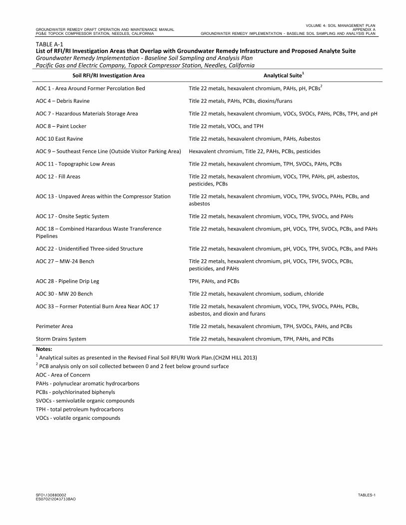
VOLUME 4: SOIL MANAGEMENT PLAN GROUNDWATER REMEDY DRAFT OPERATION AND MAINTENANCE MANUAL APPENDIX A PG&E TOPOCK COMPRESSOR STATION, NEEDLES, CALIFORNIA GROUNDWATER REMEDY IMPLEMENTATION - BASELINE SOIL SAMPLING AND ANALYSIS PLAN
SFO\130880002 TABLES-1 ES070212043733BAO
TABLE A-1 List of RFI/RI Investigation Areas that Overlap with Groundwater Remedy Infrastructure and Proposed Analyte Suite Groundwater Remedy Implementation - Baseline Soil Sampling and Analysis Plan Pacific Gas and Electric Company, Topock Compressor Station, Needles, California
Soil RFI/RI Investigation Area Analytical Suite1
AOC 1 - Area Around Former Percolation Bed Title 22 metals, hexavalent chromium, PAHs, pH, PCBs2
AOC 4 – Debris Ravine Title 22 metals, PAHs, PCBs, dioxins/furans
AOC 7 - Hazardous Materials Storage Area Title 22 metals, hexavalent chromium, VOCs, SVOCs, PAHs, PCBs, TPH, and pH
AOC 8 – Paint Locker Title 22 metals, VOCs, and TPH
AOC 10 East Ravine Title 22 metals, hexavalent chromium, PAHs, Asbestos
AOC 9 – Southeast Fence Line (Outside Visitor Parking Area) Hexavalent chromium, Title 22, PAHs, PCBs, pesticides
AOC 11 - Topographic Low Areas Title 22 metals, hexavalent chromium, TPH, SVOCs, PAHs, PCBs
AOC 12 - Fill Areas Title 22 metals, hexavalent chromium, VOCs, TPH, PAHs, pH, asbestos, pesticides, PCBs
AOC 13 - Unpaved Areas within the Compressor Station Title 22 metals, hexavalent chromium, VOCs, TPH, SVOCs, PAHs, PCBs, and asbestos
AOC 17 - Onsite Septic System Title 22 metals, hexavalent chromium, VOCs, TPH, SVOCs, and PAHs
AOC 18 – Combined Hazardous Waste Transference Pipelines
Title 22 metals, hexavalent chromium, pH, VOCs, TPH, SVOCs, PCBs, and PAHs
AOC 22 - Unidentified Three-sided Structure Title 22 metals, hexavalent chromium, pH, VOCs, TPH, SVOCs, PCBs, and PAHs
AOC 27 – MW-24 Bench Title 22 metals, hexavalent chromium, pH, VOCs, TPH, SVOCs, PCBs, pesticides, and PAHs
AOC 28 - Pipeline Drip Leg TPH, PAHs, and PCBs
AOC 30 - MW 20 Bench Title 22 metals, hexavalent chromium, sodium, chloride
AOC 33 – Former Potential Burn Area Near AOC 17 Title 22 metals, hexavalent chromium, VOCs, TPH, SVOCs, PAHs, PCBs, asbestos, and dioxin and furans
Perimeter Area Title 22 metals, hexavalent chromium, TPH, SVOCs, PAHs, and PCBs
Storm Drains System Title 22 metals, hexavalent chromium, TPH, PAHs, and PCBs
Notes: 1 Analytical suites as presented in the Revised Final Soil RFI/RI Work Plan.(CH2M HILL 2013) 2 PCB analysis only on soil collected between 0 and 2 feet below ground surface AOC - Area of Concern PAHs - polynuclear aromatic hydrocarbons PCBs - polychlorinated biphenyls SVOCs - semivolatile organic compounds TPH - total petroleum hydrocarbons VOCs - volatile organic compounds

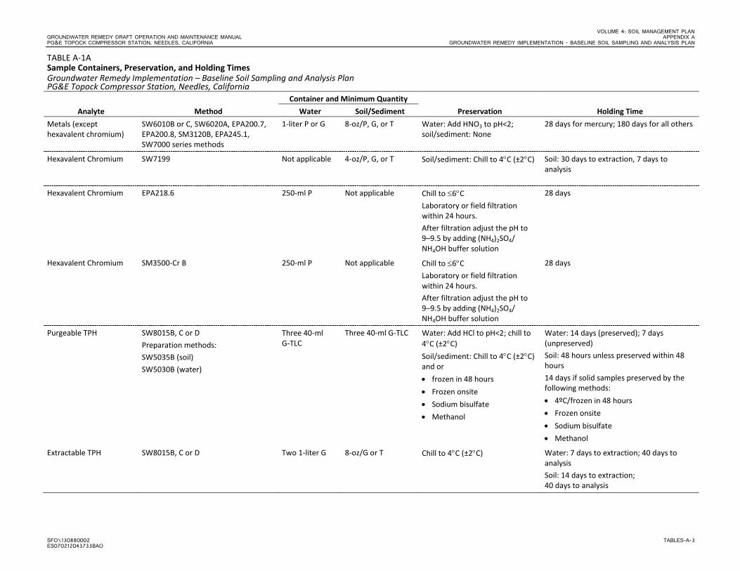
VOLUME 4: SOIL MANAGEMENT PLAN GROUNDWATER REMEDY DRAFT OPERATION AND MAINTENANCE MANUAL APPENDIX A PG&E TOPOCK COMPRESSOR STATION, NEEDLES, CALIFORNIA GROUNDWATER REMEDY IMPLEMENTATION - BASELINE SOIL SAMPLING AND ANALYSIS PLAN
SFO\130880002 TABLES-A-3 ES070212043733BAO
TABLE A-1A Sample Containers, Preservation, and Holding Times Groundwater Remedy Implementation – Baseline Soil Sampling and Analysis Plan PG&E Topock Compressor Station, Needles, California
Analyte Method Container and Minimum Quantity
Preservation Holding Time Water Soil/Sediment Metals (except hexavalent chromium)
SW6010B or C, SW6020A, EPA200.7, EPA200.8, SM3120B, EPA245.1, SW7000 series methods
1-liter P or G 8-oz/P, G, or T Water: Add HNO3 to pH<2; soil/sediment: None
28 days for mercury; 180 days for all others
Hexavalent Chromium SW7199 Not applicable 4-oz/P, G, or T Soil/sediment: Chill to 4°C (±2°C) Soil: 30 days to extraction, 7 days to analysis
Hexavalent Chromium EPA218.6 250-ml P Not applicable Chill to ≤6°C Laboratory or field filtration within 24 hours. After filtration adjust the pH to 9–9.5 by adding (NH4)2SO4/
28 days
NH4OH buffer solution
Hexavalent Chromium SM3500-Cr B 250-ml P Not applicable Chill to ≤6°C Laboratory or field filtration within 24 hours. After filtration adjust the pH to 9–9.5 by adding (NH4)2SO4/
28 days
NH4OH buffer solution
Purgeable TPH SW8015B, C or D Preparation methods: SW5035B (soil) SW5030B (water)
Three 40-ml G-TLC
Three 40-ml G-TLC Water: Add HCl to pH<2; chill to 4°C (±2°C) Soil/sediment: Chill to 4°C (±2°C) and or • frozen in 48 hours • Frozen onsite • Sodium bisulfate • Methanol
Water: 14 days (preserved); 7 days (unpreserved) Soil: 48 hours unless preserved within 48 hours 14 days if solid samples preserved by the following methods: • 4ºC/frozen in 48 hours • Frozen onsite • Sodium bisulfate • Methanol
Extractable TPH SW8015B, C or D Two 1-liter G 8-oz/G or T Chill to 4°C (±2°C) Water: 7 days to extraction; 40 days to analysis Soil: 14 days to extraction; 40 days to analysis
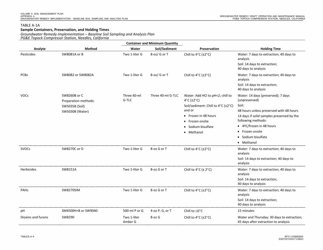
VOLUME 4: SOIL MANAGEMENT PLAN APPENDIX A GROUNDWATER REMEDY DRAFT OPERATION AND MAINTENANCE MANUAL GROUNDWATER REMEDY IMPLEMENTATION - BASELINE SOIL SAMPLING AND ANALYSIS PLAN PG&E TOPOCK COMPRESSOR STATION, NEEDLES, CALIFORNIA
TABLES-A-4 SFO\130880002 ES070212043733BAO
TABLE A-1A Sample Containers, Preservation, and Holding Times Groundwater Remedy Implementation – Baseline Soil Sampling and Analysis Plan PG&E Topock Compressor Station, Needles, California
Analyte Method Container and Minimum Quantity
Preservation Holding Time Water Soil/Sediment Pesticides SW8081A or B Two 1-liter G 8-oz/ G or T Chill to 4°C (±2°C) Water: 7 days to extraction; 40 days to
analysis Soil: 14 days to extraction; 40 days to analysis
PCBs SW8082 or SW8082A Two 1-liter G 8-oz/ G or T Chill to 4°C (±2°C) Water: 7 days to extraction; 40 days to analysis Soil: 14 days to extraction; 40 days to analysis
VOCs SW8260B or C Preparation methods: SW5035B (Soil) SW5030B (Water)
Three 40-ml G-TLC
Three 40-ml G-TLC Water: Add HCl to pH<2; chill to 4°C (±2°C) Soil/sediment: Chill to 4°C (±2°C) and or • Frozen in 48 hours • Frozen onsite • Sodium bisulfate • Methanol
Water: 14 days (preserved); 7 days (unpreserved) Soil: 48 hours unless preserved with 48 hours 14 days if solid samples preserved by the following methods: • 4ºC/frozen in 48 hours • Frozen onsite • Sodium bisulfate • Methanol
SVOCs SW8270C or D Two 1-liter G 8-oz G or T Chill to 4°C (±2°C) Water: 7 days to extraction; 40 days to analysis Soil: 14 days to extraction; 40 days to analysis
Herbicides SW8151A Two 1-liter G 8-oz G or T Chill to 4°C (± 2°C) Water: 7 days to extraction; 40 days to analysis Soil: 14 days to extraction; 40 days to analysis
PAHs SW8270SIM Two 1-liter G 8-oz G or T Chill to 4°C (±2°C) Water: 7 days to extraction; 40 days to analysis Soil: 14 days to extraction; 40 days to analysis
pH SM4500H+B or SW9040 500-ml P or G 4-oz P, G, or T Chill to ≤6°C 15 minutes
Dioxins and furans SW8290 Two 1-liter Amber G
8-oz G Chill to 4°C (±2°C) Water and Thursday: 30 days to extraction; 45 days after extraction to analysis
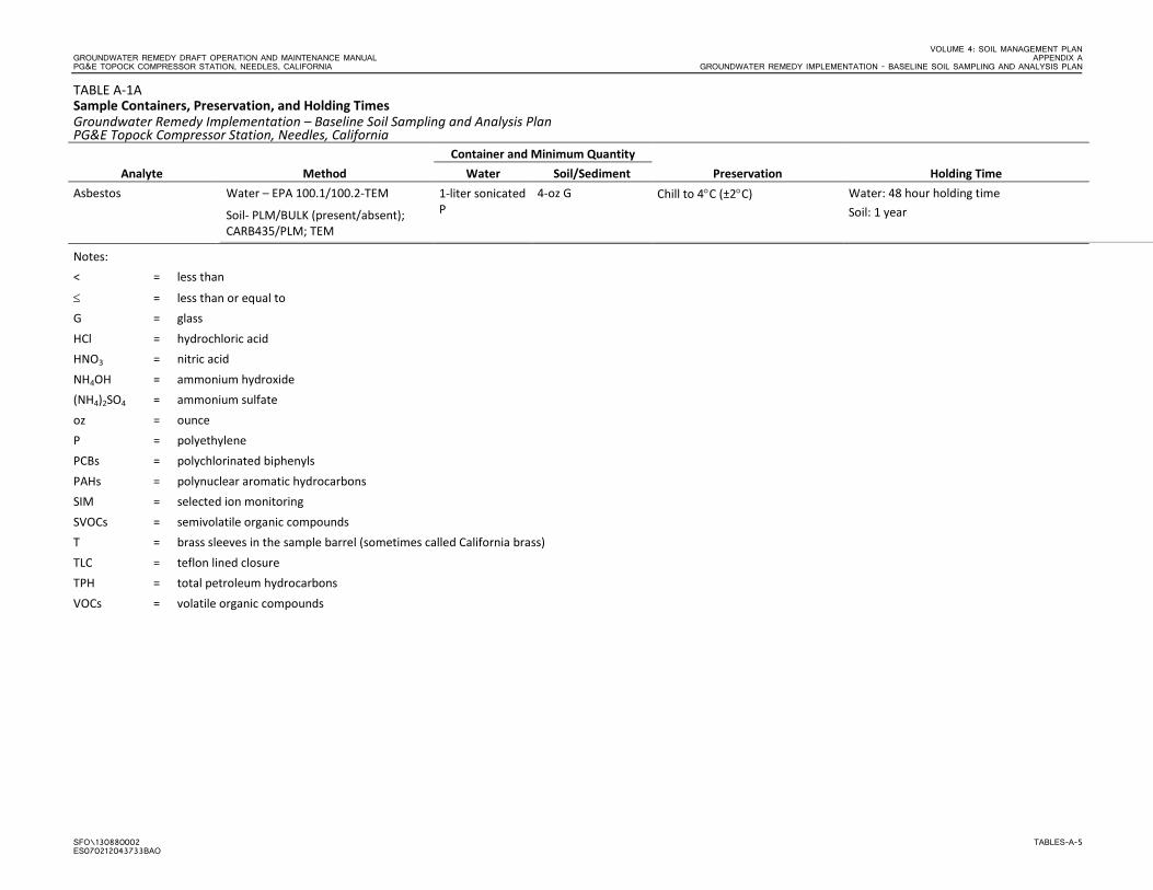
VOLUME 4: SOIL MANAGEMENT PLAN GROUNDWATER REMEDY DRAFT OPERATION AND MAINTENANCE MANUAL APPENDIX A PG&E TOPOCK COMPRESSOR STATION, NEEDLES, CALIFORNIA GROUNDWATER REMEDY IMPLEMENTATION - BASELINE SOIL SAMPLING AND ANALYSIS PLAN
SFO\130880002 TABLES-A-5 ES070212043733BAO
TABLE A-1A Sample Containers, Preservation, and Holding Times Groundwater Remedy Implementation – Baseline Soil Sampling and Analysis Plan PG&E Topock Compressor Station, Needles, California
Analyte Method Container and Minimum Quantity
Preservation Holding Time Water Soil/Sediment Asbestos Water – EPA 100.1/100.2-TEM
Soil- PLM/BULK (present/absent); CARB435/PLM; TEM
1-liter sonicated P
4-oz G Chill to 4°C (±2°C) Water: 48 hour holding time Soil: 1 year
Notes: < = less than
≤ = less than or equal to G = glass HCl = hydrochloric acid HNO3 = nitric acid NH4OH = ammonium hydroxide (NH4)2SO4 = ammonium sulfate oz = ounce P = polyethylene PCBs = polychlorinated biphenyls PAHs = polynuclear aromatic hydrocarbons SIM = selected ion monitoring SVOCs = semivolatile organic compounds T = brass sleeves in the sample barrel (sometimes called California brass) TLC = teflon lined closure TPH = total petroleum hydrocarbons VOCs = volatile organic compounds

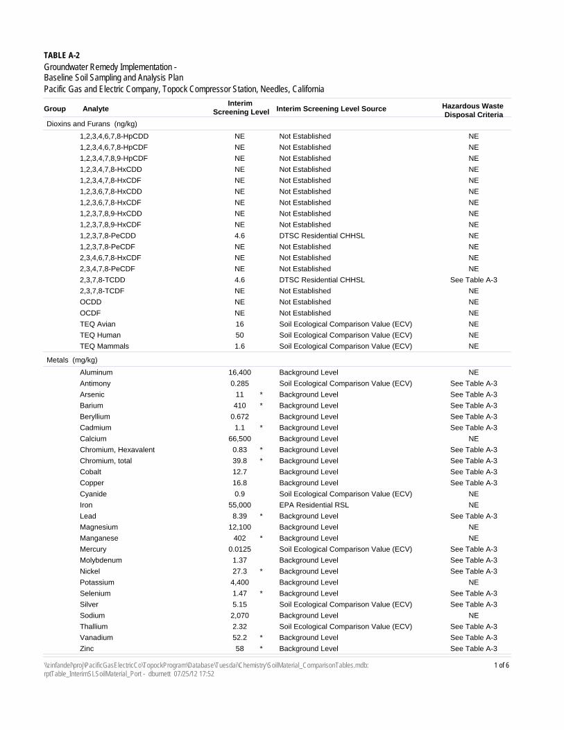
Interim Screening Level SourceInterim
Screening LevelAnalyteGroup
TABLE A-2
Groundwater Remedy Implementation - Baseline Soil Sampling and Analysis PlanPacific Gas and Electric Company, Topock Compressor Station, Needles, California
Hazardous Waste Disposal Criteria
Dioxins and Furans (ng/kg)
Not EstablishedNE1,2,3,4,6,7,8-HpCDD NE
Not EstablishedNE1,2,3,4,6,7,8-HpCDF NE
Not EstablishedNE1,2,3,4,7,8,9-HpCDF NE
Not EstablishedNE1,2,3,4,7,8-HxCDD NE
Not EstablishedNE1,2,3,4,7,8-HxCDF NE
Not EstablishedNE1,2,3,6,7,8-HxCDD NE
Not EstablishedNE1,2,3,6,7,8-HxCDF NE
Not EstablishedNE1,2,3,7,8,9-HxCDD NE
Not EstablishedNE1,2,3,7,8,9-HxCDF NE
DTSC Residential CHHSL4.61,2,3,7,8-PeCDD NE
Not EstablishedNE1,2,3,7,8-PeCDF NE
Not EstablishedNE2,3,4,6,7,8-HxCDF NE
Not EstablishedNE2,3,4,7,8-PeCDF NE
DTSC Residential CHHSL4.62,3,7,8-TCDD See Table A-3
Not EstablishedNE2,3,7,8-TCDF NE
Not EstablishedNEOCDD NE
Not EstablishedNEOCDF NE
Soil Ecological Comparison Value (ECV)16TEQ Avian NE
Soil Ecological Comparison Value (ECV)50TEQ Human NE
Soil Ecological Comparison Value (ECV)1.6TEQ Mammals NE
Metals (mg/kg)
Background Level16,400Aluminum NE
Soil Ecological Comparison Value (ECV)0.285Antimony See Table A-3
Background Level11Arsenic See Table A-3*
Background Level410Barium See Table A-3*
Background Level0.672Beryllium See Table A-3
Background Level1.1Cadmium See Table A-3*
Background Level66,500Calcium NE
Background Level0.83Chromium, Hexavalent See Table A-3*
Background Level39.8Chromium, total See Table A-3*
Background Level12.7Cobalt See Table A-3
Background Level16.8Copper See Table A-3
Soil Ecological Comparison Value (ECV)0.9Cyanide NE
EPA Residential RSL55,000Iron NE
Background Level8.39Lead See Table A-3*
Background Level12,100Magnesium NE
Background Level402Manganese NE*
Soil Ecological Comparison Value (ECV)0.0125Mercury See Table A-3
Background Level1.37Molybdenum See Table A-3
Background Level27.3Nickel See Table A-3*
Background Level4,400Potassium NE
Background Level1.47Selenium See Table A-3*
Soil Ecological Comparison Value (ECV)5.15Silver See Table A-3
Background Level2,070Sodium NE
Soil Ecological Comparison Value (ECV)2.32Thallium See Table A-3
Background Level52.2Vanadium See Table A-3*
Background Level58Zinc See Table A-3*
1 of 6\\zinfandel\proj\PacificGasElectricCo\TopockProgram\Database\Tuesdai\Chemistry\SoilMaterial_ComparisonTables.mdb: rptTable_InterimSLSoilMaterial_Port - dburnett 07/25/12 17:52
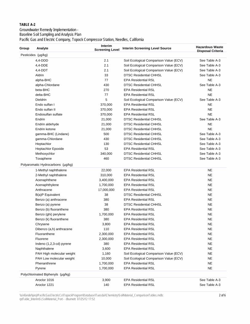
Interim Screening Level SourceInterim
Screening LevelAnalyteGroup
TABLE A-2
Groundwater Remedy Implementation - Baseline Soil Sampling and Analysis PlanPacific Gas and Electric Company, Topock Compressor Station, Needles, California
Hazardous Waste Disposal Criteria
Pesticides (µg/kg)
Soil Ecological Comparison Value (ECV)2.14,4-DDD See Table A-3
Soil Ecological Comparison Value (ECV)2.14,4-DDE See Table A-3
Soil Ecological Comparison Value (ECV)2.14,4-DDT See Table A-3
DTSC Residential CHHSL33Aldrin See Table A-3
EPA Residential RSL77alpha-BHC NE
DTSC Residential CHHSL430alpha-Chlordane See Table A-3
EPA Residential RSL270beta-BHC NE
EPA Residential RSL77delta-BHC NE
Soil Ecological Comparison Value (ECV)5Dieldrin See Table A-3
EPA Residential RSL370,000Endo sulfan I NE
EPA Residential RSL370,000Endo sulfan II NE
EPA Residential RSL370,000Endosulfan sulfate NE
DTSC Residential CHHSL21,000Endrin See Table A-3
DTSC Residential CHHSL21,000Endrin aldehyde NE
DTSC Residential CHHSL21,000Endrin ketone NE
DTSC Residential CHHSL500gamma-BHC (Lindane) See Table A-3
DTSC Residential CHHSL430gamma-Chlordane See Table A-3
DTSC Residential CHHSL130Heptachlor See Table A-3
EPA Residential RSL53Heptachlor Epoxide See Table A-3
DTSC Residential CHHSL340,000Methoxychlor See Table A-3
DTSC Residential CHHSL460Toxaphene See Table A-3
Polyaromatic Hydrocarbons (µg/kg)
EPA Residential RSL22,0001-Methyl naphthalene NE
EPA Residential RSL310,0002-Methyl naphthalene NE
EPA Residential RSL3,400,000Acenaphthene NE
EPA Residential RSL1,700,000Acenaphthylene NE
EPA Residential RSL17,000,000Anthracene NE
DTSC Residential CHHSL38B(a)P Equivalent NE
EPA Residential RSL380Benzo (a) anthracene NE
DTSC Residential CHHSL38Benzo (a) pyrene NE
EPA Residential RSL380Benzo (b) fluoranthene NE
EPA Residential RSL1,700,000Benzo (ghi) perylene NE
EPA Residential RSL380Benzo (k) fluoranthene NE
EPA Residential RSL3,800Chrysene NE
EPA Residential RSL110Dibenzo (a,h) anthracene NE
EPA Residential RSL2,300,000Fluoranthene NE
EPA Residential RSL2,300,000Fluorene NE
EPA Residential RSL380Indeno (1,2,3-cd) pyrene NE
EPA Residential RSL3,600Naphthalene NE
Soil Ecological Comparison Value (ECV)1,160PAH High molecular weight NE
Soil Ecological Comparison Value (ECV)10,000PAH Low molecular weight NE
EPA Residential RSL1,700,000Phenanthrene NE
EPA Residential RSL1,700,000Pyrene NE
Polychlorinated Biphenyls (µg/kg)
EPA Residential RSL3,900Aroclor 1016 See Table A-3
EPA Residential RSL140Aroclor 1221 See Table A-3
2 of 6\\zinfandel\proj\PacificGasElectricCo\TopockProgram\Database\Tuesdai\Chemistry\SoilMaterial_ComparisonTables.mdb: rptTable_InterimSLSoilMaterial_Port - dburnett 07/25/12 17:52
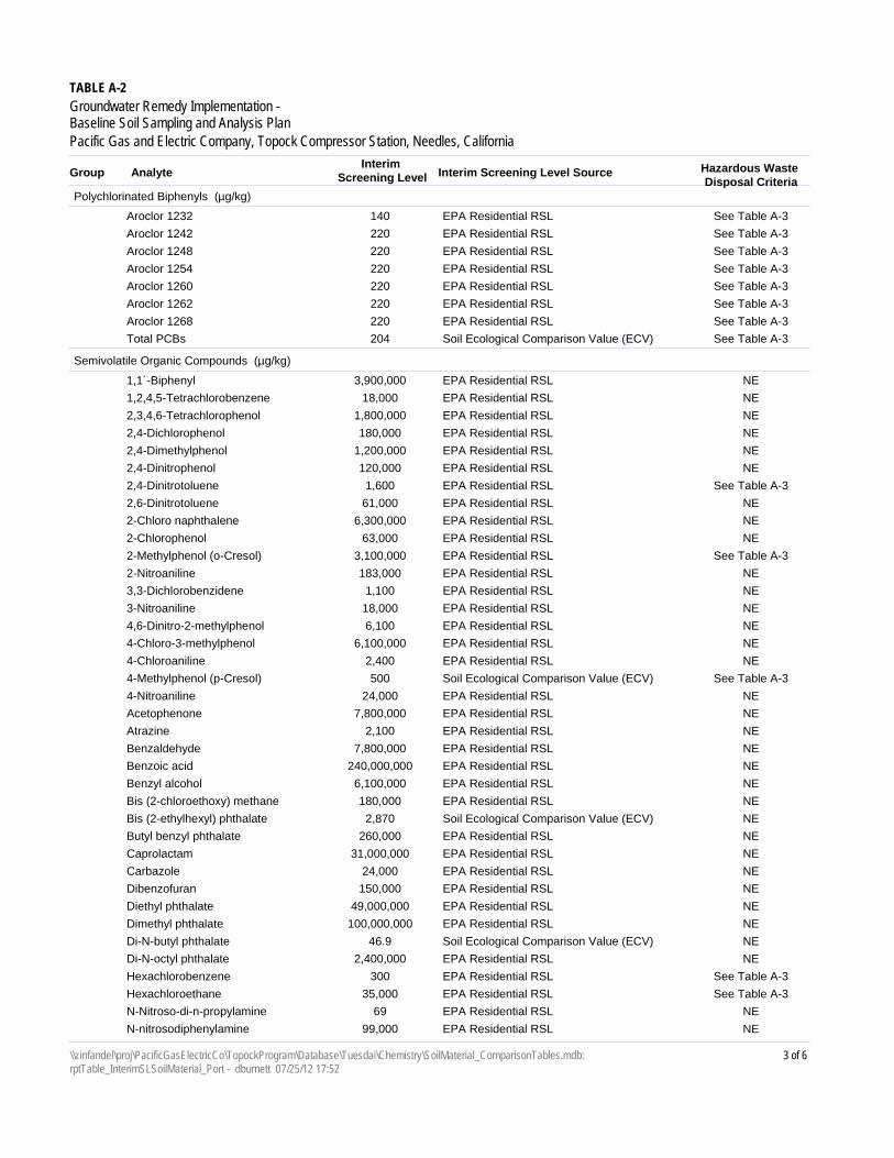
Interim Screening Level SourceInterim
Screening LevelAnalyteGroup
TABLE A-2
Groundwater Remedy Implementation - Baseline Soil Sampling and Analysis PlanPacific Gas and Electric Company, Topock Compressor Station, Needles, California
Hazardous Waste Disposal Criteria
Polychlorinated Biphenyls (µg/kg)
EPA Residential RSL140Aroclor 1232 See Table A-3
EPA Residential RSL220Aroclor 1242 See Table A-3
EPA Residential RSL220Aroclor 1248 See Table A-3
EPA Residential RSL220Aroclor 1254 See Table A-3
EPA Residential RSL220Aroclor 1260 See Table A-3
EPA Residential RSL220Aroclor 1262 See Table A-3
EPA Residential RSL220Aroclor 1268 See Table A-3
Soil Ecological Comparison Value (ECV)204Total PCBs See Table A-3
Semivolatile Organic Compounds (µg/kg)
EPA Residential RSL3,900,0001,1´-Biphenyl NE
EPA Residential RSL18,0001,2,4,5-Tetrachlorobenzene NE
EPA Residential RSL1,800,0002,3,4,6-Tetrachlorophenol NE
EPA Residential RSL180,0002,4-Dichlorophenol NE
EPA Residential RSL1,200,0002,4-Dimethylphenol NE
EPA Residential RSL120,0002,4-Dinitrophenol NE
EPA Residential RSL1,6002,4-Dinitrotoluene See Table A-3
EPA Residential RSL61,0002,6-Dinitrotoluene NE
EPA Residential RSL6,300,0002-Chloro naphthalene NE
EPA Residential RSL63,0002-Chlorophenol NE
EPA Residential RSL3,100,0002-Methylphenol (o-Cresol) See Table A-3
EPA Residential RSL183,0002-Nitroaniline NE
EPA Residential RSL1,1003,3-Dichlorobenzidene NE
EPA Residential RSL18,0003-Nitroaniline NE
EPA Residential RSL6,1004,6-Dinitro-2-methylphenol NE
EPA Residential RSL6,100,0004-Chloro-3-methylphenol NE
EPA Residential RSL2,4004-Chloroaniline NE
Soil Ecological Comparison Value (ECV)5004-Methylphenol (p-Cresol) See Table A-3
EPA Residential RSL24,0004-Nitroaniline NE
EPA Residential RSL7,800,000Acetophenone NE
EPA Residential RSL2,100Atrazine NE
EPA Residential RSL7,800,000Benzaldehyde NE
EPA Residential RSL240,000,000Benzoic acid NE
EPA Residential RSL6,100,000Benzyl alcohol NE
EPA Residential RSL180,000Bis (2-chloroethoxy) methane NE
Soil Ecological Comparison Value (ECV)2,870Bis (2-ethylhexyl) phthalate NE
EPA Residential RSL260,000Butyl benzyl phthalate NE
EPA Residential RSL31,000,000Caprolactam NE
EPA Residential RSL24,000Carbazole NE
EPA Residential RSL150,000Dibenzofuran NE
EPA Residential RSL49,000,000Diethyl phthalate NE
EPA Residential RSL100,000,000Dimethyl phthalate NE
Soil Ecological Comparison Value (ECV)46.9Di-N-butyl phthalate NE
EPA Residential RSL2,400,000Di-N-octyl phthalate NE
EPA Residential RSL300Hexachlorobenzene See Table A-3
EPA Residential RSL35,000Hexachloroethane See Table A-3
EPA Residential RSL69N-Nitroso-di-n-propylamine NE
EPA Residential RSL99,000N-nitrosodiphenylamine NE
3 of 6\\zinfandel\proj\PacificGasElectricCo\TopockProgram\Database\Tuesdai\Chemistry\SoilMaterial_ComparisonTables.mdb: rptTable_InterimSLSoilMaterial_Port - dburnett 07/25/12 17:52
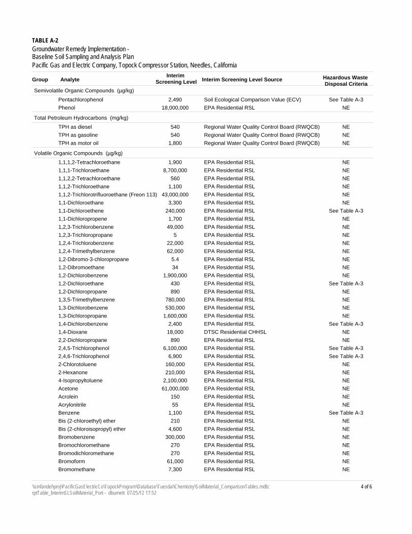
Interim Screening Level SourceInterim
Screening LevelAnalyteGroup
TABLE A-2
Groundwater Remedy Implementation - Baseline Soil Sampling and Analysis PlanPacific Gas and Electric Company, Topock Compressor Station, Needles, California
Hazardous Waste Disposal Criteria
Semivolatile Organic Compounds (µg/kg)
Soil Ecological Comparison Value (ECV)2,490Pentachlorophenol See Table A-3
EPA Residential RSL18,000,000Phenol NE
Total Petroleum Hydrocarbons (mg/kg)
Regional Water Quality Control Board (RWQCB)540TPH as diesel NE
Regional Water Quality Control Board (RWQCB)540TPH as gasoline NE
Regional Water Quality Control Board (RWQCB)1,800TPH as motor oil NE
Volatile Organic Compounds (µg/kg)
EPA Residential RSL1,9001,1,1,2-Tetrachloroethane NE
EPA Residential RSL8,700,0001,1,1-Trichloroethane NE
EPA Residential RSL5601,1,2,2-Tetrachloroethane NE
EPA Residential RSL1,1001,1,2-Trichloroethane NE
EPA Residential RSL43,000,0001,1,2-Trichlorotrifluoroethane (Freon 113) NE
EPA Residential RSL3,3001,1-Dichloroethane NE
EPA Residential RSL240,0001,1-Dichloroethene See Table A-3
EPA Residential RSL1,7001,1-Dichloropropene NE
EPA Residential RSL49,0001,2,3-Trichlorobenzene NE
EPA Residential RSL51,2,3-Trichloropropane NE
EPA Residential RSL22,0001,2,4-Trichlorobenzene NE
EPA Residential RSL62,0001,2,4-Trimethylbenzene NE
EPA Residential RSL5.41,2-Dibromo-3-chloropropane NE
EPA Residential RSL341,2-Dibromoethane NE
EPA Residential RSL1,900,0001,2-Dichlorobenzene NE
EPA Residential RSL4301,2-Dichloroethane See Table A-3
EPA Residential RSL8901,2-Dichloropropane NE
EPA Residential RSL780,0001,3,5-Trimethylbenzene NE
EPA Residential RSL530,0001,3-Dichlorobenzene NE
EPA Residential RSL1,600,0001,3-Dichloropropane NE
EPA Residential RSL2,4001,4-Dichlorobenzene See Table A-3
DTSC Residential CHHSL18,0001,4-Dioxane NE
EPA Residential RSL8902,2-Dichloropropane NE
EPA Residential RSL6,100,0002,4,5-Trichlorophenol See Table A-3
EPA Residential RSL6,9002,4,6-Trichlorophenol See Table A-3
EPA Residential RSL160,0002-Chlorotoluene NE
EPA Residential RSL210,0002-Hexanone NE
EPA Residential RSL2,100,0004-Isopropyltoluene NE
EPA Residential RSL61,000,000Acetone NE
EPA Residential RSL150Acrolein NE
EPA Residential RSL55Acrylonitrile NE
EPA Residential RSL1,100Benzene See Table A-3
EPA Residential RSL210Bis (2-chloroethyl) ether NE
EPA Residential RSL4,600Bis (2-chloroisopropyl) ether NE
EPA Residential RSL300,000Bromobenzene NE
EPA Residential RSL270Bromochloromethane NE
EPA Residential RSL270Bromodichloromethane NE
EPA Residential RSL61,000Bromoform NE
EPA Residential RSL7,300Bromomethane NE
4 of 6\\zinfandel\proj\PacificGasElectricCo\TopockProgram\Database\Tuesdai\Chemistry\SoilMaterial_ComparisonTables.mdb: rptTable_InterimSLSoilMaterial_Port - dburnett 07/25/12 17:52
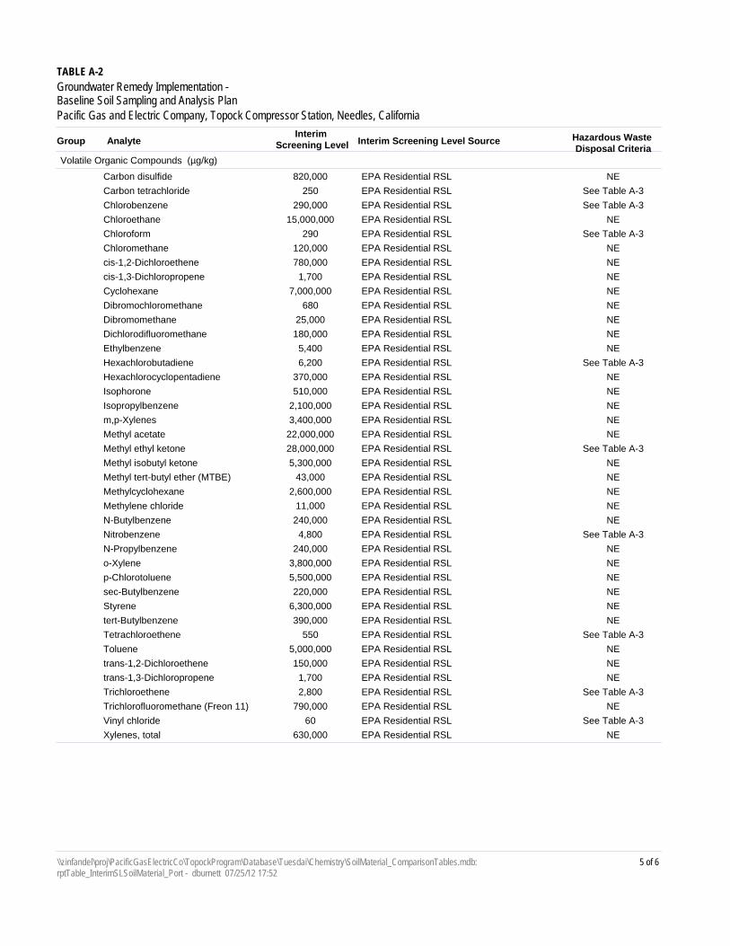
Interim Screening Level SourceInterim
Screening LevelAnalyteGroup
TABLE A-2
Groundwater Remedy Implementation - Baseline Soil Sampling and Analysis PlanPacific Gas and Electric Company, Topock Compressor Station, Needles, California
Hazardous Waste Disposal Criteria
Volatile Organic Compounds (µg/kg)
EPA Residential RSL820,000Carbon disulfide NE
EPA Residential RSL250Carbon tetrachloride See Table A-3
EPA Residential RSL290,000Chlorobenzene See Table A-3
EPA Residential RSL15,000,000Chloroethane NE
EPA Residential RSL290Chloroform See Table A-3
EPA Residential RSL120,000Chloromethane NE
EPA Residential RSL780,000cis-1,2-Dichloroethene NE
EPA Residential RSL1,700cis-1,3-Dichloropropene NE
EPA Residential RSL7,000,000Cyclohexane NE
EPA Residential RSL680Dibromochloromethane NE
EPA Residential RSL25,000Dibromomethane NE
EPA Residential RSL180,000Dichlorodifluoromethane NE
EPA Residential RSL5,400Ethylbenzene NE
EPA Residential RSL6,200Hexachlorobutadiene See Table A-3
EPA Residential RSL370,000Hexachlorocyclopentadiene NE
EPA Residential RSL510,000Isophorone NE
EPA Residential RSL2,100,000Isopropylbenzene NE
EPA Residential RSL3,400,000m,p-Xylenes NE
EPA Residential RSL22,000,000Methyl acetate NE
EPA Residential RSL28,000,000Methyl ethyl ketone See Table A-3
EPA Residential RSL5,300,000Methyl isobutyl ketone NE
EPA Residential RSL43,000Methyl tert-butyl ether (MTBE) NE
EPA Residential RSL2,600,000Methylcyclohexane NE
EPA Residential RSL11,000Methylene chloride NE
EPA Residential RSL240,000N-Butylbenzene NE
EPA Residential RSL4,800Nitrobenzene See Table A-3
EPA Residential RSL240,000N-Propylbenzene NE
EPA Residential RSL3,800,000o-Xylene NE
EPA Residential RSL5,500,000p-Chlorotoluene NE
EPA Residential RSL220,000sec-Butylbenzene NE
EPA Residential RSL6,300,000Styrene NE
EPA Residential RSL390,000tert-Butylbenzene NE
EPA Residential RSL550Tetrachloroethene See Table A-3
EPA Residential RSL5,000,000Toluene NE
EPA Residential RSL150,000trans-1,2-Dichloroethene NE
EPA Residential RSL1,700trans-1,3-Dichloropropene NE
EPA Residential RSL2,800Trichloroethene See Table A-3
EPA Residential RSL790,000Trichlorofluoromethane (Freon 11) NE
EPA Residential RSL60Vinyl chloride See Table A-3
EPA Residential RSL630,000Xylenes, total NE
5 of 6\\zinfandel\proj\PacificGasElectricCo\TopockProgram\Database\Tuesdai\Chemistry\SoilMaterial_ComparisonTables.mdb: rptTable_InterimSLSoilMaterial_Port - dburnett 07/25/12 17:52

Notes:
California Department of Toxic Substances Control; California human health screening levels (OEHHA, 2005)
milligrams per kilogram
DTSC CHHSL
mg/kg
Interim screening level is background value. If background value is not available then the lesser of the DTSC residential CHHSL or the ecological comparison value is used. If CHHSL is not available, it is the lesser of the USEPA residential regional screening level or the ecological comparison value.
Background "Final Soil Background Investigation at Pacific Gas and Electric Company Topock Compressor Station, Needles, California" (CH2M HIll, May 2009)
United States Environmental Protection Agency Regional Screening Level, various dates. See Tables 3-1 to 3-8 of the Soil Investigation Part A Phase 1 Data Gaps Evaluation Report dated May 2011 for respective dates for each RSL.
EPA RSL
micrograms per kilogramµg/kg
Ecological Comparison Values; ECV were calculated as needed for constituents detected during the Part APhase I sampling (Arcadis, 2008)
ECV
"San Francisco Bay Regional Water Quality Control Board Environmental Screening Levels, Screening For Environmental Concerns at Sites With Contaminated Soil and Groundwater" (Table K-1). May 27, 2008
RWQCB
nanograms per kilogramng/kg
This table presents a reference list of analytes and associated screening levels that may be applicable for making decisions related to disposition of displaced site materials. The specific analytes and screening levels applicable for characterization of displaced material will be determined based on the origin of the material and potential disposition locations.
not establishedNE
One or more screening levels (EPA RSL, DTSC CHHSL, ECV, or Soil SL) have values lower than the background level.*
6 of 6\\zinfandel\proj\PacificGasElectricCo\TopockProgram\Database\Tuesdai\Chemistry\SoilMaterial_ComparisonTables.mdb: rptTable_InterimSLSoilMaterial_Port - dburnett 07/25/12 17:52
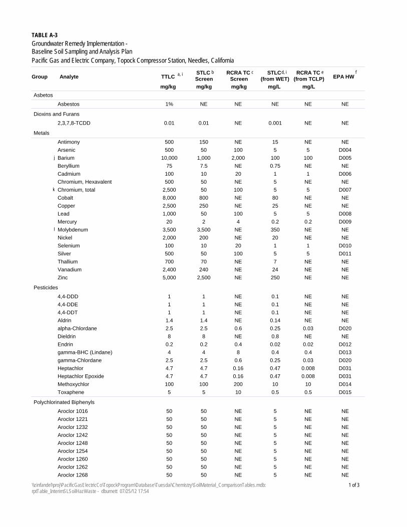
TABLE A-3
Groundwater Remedy Implementation - Baseline Soil Sampling and Analysis PlanPacific Gas and Electric Company, Topock Compressor Station, Needles, California
TTLCAnalyteGroupSTLC Screen
RCRA TC Screen
STLC (from WET)
RCRA TC (from TCLP)
mg/kg mg/kg mg/kg mg/L mg/L
a, i b d, ic eEPA HW
f
Asbetos
1%Asbestos NE NE NE NE NE
Dioxins and Furans
0.012,3,7,8-TCDD 0.01 NE 0.001 NE NE
Metals
500Antimony 150 NE 15 NE NE
500Arsenic 50 100 5 5 D004
10,000Barium 1,000 2,000 100 100j D005
75Beryllium 7.5 NE 0.75 NE NE
100Cadmium 10 20 1 1 D006
500Chromium, Hexavalent 50 NE 5 NE NE
2,500Chromium, total 50 100 5 5k D007
8,000Cobalt 800 NE 80 NE NE
2,500Copper 250 NE 25 NE NE
1,000Lead 50 100 5 5 D008
20Mercury 2 4 0.2 0.2 D009
3,500Molybdenum 3,500 NE 350 NEl NE
2,000Nickel 200 NE 20 NE NE
100Selenium 10 20 1 1 D010
500Silver 50 100 5 5 D011
700Thallium 70 NE 7 NE NE
2,400Vanadium 240 NE 24 NE NE
5,000Zinc 2,500 NE 250 NE NE
Pesticides
14,4-DDD 1 NE 0.1 NE NE
14,4-DDE 1 NE 0.1 NE NE
14,4-DDT 1 NE 0.1 NE NE
1.4Aldrin 1.4 NE 0.14 NE NE
2.5alpha-Chlordane 2.5 0.6 0.25 0.03 D020
8Dieldrin 8 NE 0.8 NE NE
0.2Endrin 0.2 0.4 0.02 0.02 D012
4gamma-BHC (Lindane) 4 8 0.4 0.4 D013
2.5gamma-Chlordane 2.5 0.6 0.25 0.03 D020
4.7Heptachlor 4.7 0.16 0.47 0.008 D031
4.7Heptachlor Epoxide 4.7 0.16 0.47 0.008 D031
100Methoxychlor 100 200 10 10 D014
5Toxaphene 5 10 0.5 0.5 D015
Polychlorinated Biphenyls
50Aroclor 1016 50 NE 5 NE NE
50Aroclor 1221 50 NE 5 NE NE
50Aroclor 1232 50 NE 5 NE NE
50Aroclor 1242 50 NE 5 NE NE
50Aroclor 1248 50 NE 5 NE NE
50Aroclor 1254 50 NE 5 NE NE
50Aroclor 1260 50 NE 5 NE NE
50Aroclor 1262 50 NE 5 NE NE
50Aroclor 1268 50 NE 5 NE NE
1 of 3\\zinfandel\proj\PacificGasElectricCo\TopockProgram\Database\Tuesdai\Chemistry\SoilMaterial_ComparisonTables.mdb: rptTable_InterimSLSoilHazWaste - dburnett 07/25/12 17:54
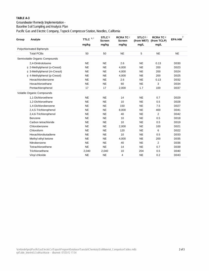
TABLE A-3
Groundwater Remedy Implementation -Baseline Soil Sampling and Analysis PlanPacific Gas and Electric Company, Topock Compressor Station, Needles, California
TTLCAnalyteGroupSTLC Screen
RCRA TC Screen
STLC (from WET)
RCRA TC (from TCLP)
mg/kg mg/kg mg/kg mg/L mg/L
a, i b d, ic eEPA HW
f
Polychlorinated Biphenyls
50Total PCBs 50 NE 5 NE NE
Semivolatile Organic Compounds
NE2,4-Dinitrotoluene NE 2.6 NE 0.13 D030
NE2-Methylphenol (o-Cresol) NE 4,000 NE 200g D023
NE3-Methylphenol (m-Cresol) NE 4,000 NE 200g D024
NE4-Methylphenol (p-Cresol) NE 4,000 NE 200g D025
NEHexachlorobenzene NE 2.6 NE 0.13 D032
NEHexachloroethane NE 60 NE 3 D034
17Pentachlorophenol 17 2,000 1.7 100 D037
Volatile Organic Compounds
NE1,1-Dichloroethene NE 14 NE 0.7 D029
NE1,2-Dichloroethane NE 10 NE 0.5 D028
NE1,4-Dichlorobenzene NE 150 NE 7.5 D027
NE2,4,5-Trichlorophenol NE 8,000 NE 400 D041
NE2,4,6-Trichlorophenol NE 40 NE 2 D042
NEBenzene NE 10 NE 0.5 D018
NECarbon tetrachloride NE 10 NE 0.5 D019
NEChlorobenzene NE 2,000 NE 100 D021
NEChloroform NE 120 NE 6 D022
NEHexachlorobutadiene NE 10 NE 0.5 D033
NEMethyl ethyl ketone NE 4,000 NE 200 D035
NENitrobenzene NE 40 NE 2 D036
NETetrachloroethene NE 14 NE 0.7 D039
2,040Trichloroethene 2,040 10 204 0.5 D040
NEVinyl chloride NE 4 NE 0.2 D043
2 of 3\\zinfandel\proj\PacificGasElectricCo\TopockProgram\Database\Tuesdai\Chemistry\SoilMaterial_ComparisonTables.mdb: rptTable_InterimSLSoilHazWaste - dburnett 07/25/12 17:54
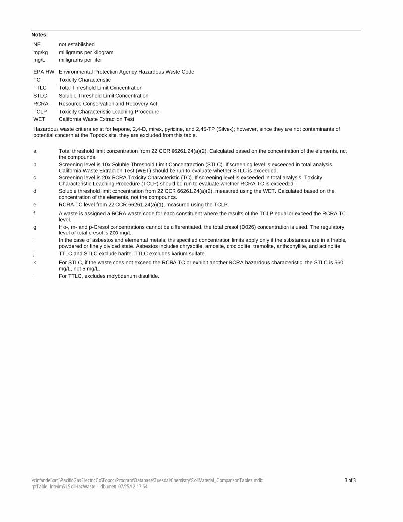
Notes:
milligrams per kilogrammg/kg
milligrams per litermg/L
not establishedNE
Total Threshold Limit ConcentrationTTLC
Soluble Threshold Limit ConcentrationSTLC
Toxicity Characteristic Leaching ProcedureTCLP
Resource Conservation and Recovery ActRCRA
Toxicity CharacteristicTC
California Waste Extraction TestWET
Environmental Protection Agency Hazardous Waste CodeEPA HW
Hazardous waste critiera exist for kepone, 2,4-D, mirex, pyridine, and 2,45-TP (Silvex); however, since they are not contaminants of potential concern at the Topock site, they are excluded from this table.
Total threshold limit concentration from 22 CCR 66261.24(a)(2). Calculated based on the concentration of the elements, not the compounds.
a
Screening level is 10x Soluble Threshold Limit Concentraction (STLC). If screening level is exceeded in total analysis, California Waste Extraction Test (WET) should be run to evaluate whether STLC is exceeded.
b
Screening level is 20x RCRA Toxicity Characteristic (TC). If screening level is exceeded in total analysis, Toxicity Characteristic Leaching Procedure (TCLP) should be run to evaluate whether RCRA TC is exceeded.
c
Soluble threshold limit concentration from 22 CCR 66261.24(a)(2), measured using the WET. Calculated based on the concentration of the elements, not the compounds.
d
RCRA TC level from 22 CCR 66261.24(a)(1), measured using the TCLP.e
A waste is assigned a RCRA waste code for each constituent where the results of the TCLP equal or exceed the RCRA TC level.
f
If o-, m- and p-Cresol concentrations cannot be differentiated, the total cresol (D026) concentration is used. The regulatory level of total cresol is 200 mg/L.
g
In the case of asbestos and elemental metals, the specified concentration limits apply only if the substances are in a friable, powdered or finely divided state. Asbestos includes chrysotile, amosite, crocidolite, tremolite, anthophyllite, and actinolite.
i
TTLC and STLC exclude barite. TTLC excludes barium sulfate.j
For STLC, if the waste does not exceed the RCRA TC or exhibit another RCRA hazardous characteristic, the STLC is 560 mg/L, not 5 mg/L.
k
For TTLC, excludes molybdenum disulfide.l
3 of 3\\zinfandel\proj\PacificGasElectricCo\TopockProgram\Database\Tuesdai\Chemistry\SoilMaterial_ComparisonTables.mdb: rptTable_InterimSLSoilHazWaste - dburnett 07/25/12 17:54

Figures


"!
"!
"!
"!
"!
"!
"S
#B
#B
#B
#B#B
#B
#B#B
#B
#B
#B
#B
#B
#B
#B
#B
#B
#B
#B
#B
#B
#B#B
"S
"S
!H
!H!H
!H
!H !H
!H
!H
!H
!H
!H
!H
!H
!H
!H
!H
!H
!H
!H
"S
"S
"S
#B
#B
#B
#B#B
#B
#B
#B
"S
#B
#B
#B
#B
#B
#B
#B
#B
"S
"S
"S
"S
"S
#B
#B
#B
#B
"S
"S
"S
"S
"S
"S
"S
#B
#B
#B
#B
Ü
Ü
Ü
Ü
Ü
Ü
Ü
ÜÜ
Ü
ÜÜ
ÜÜ Ü Ü Ü ÜÜ
Ü
Ü
Ü
Ü
Ü
Ü
Ü
Ü
Ü
Ü
Ü
Ü
Ü
Ü ÜÜ
Ü
Ü
Ü
ÜÜ
Ü
Ü
ÜÜÜ
ÜÜ
Ü
ÜÜ
Ü
Ü
ÜÜ
ÜÜ
Ü
ÜÜ
ÜÜ
Ü
Ü
Ü Ü
ÜÜÜ ÜÜ
ÜÜ
Ü
Ü
ÜÜ
Ü
Ü
Ü
ÜÜ
Ü
Ü
Ü
ÜÜ
Ü
Ü
Ü
Ü
Ü
Ü
Ü
ÜÜ
Ü Ü
Ü
ÜÜ
Ü
Ü
Ü
Ü
Ü
Ü
Ü
Ü
Ü
Ü
!(
!(
!(
!(
!(!( !(!(!(!(
!(!(!(!(
!(!(!(!(!(!(
!(
!(
!(!(
!(
!(
!(
!(!(
!(!(
!(
!(!(
!(
!(
!(
!(
!(
!(!(
!(
!(
!(
!(
!(
!(
!(
!(
!(
!(!(
!(
!(
!(!(!(
!(
!(
!(!(
!(!(
!(
!(!(
!(
!(
GF
GF
GF
GF
GF
GF !(
!(
!(
!(
!(
!(!(
!(
!(!(
!(!(
!(
!(
!(
!(
!(
!(
!(
!(!(!(
!(
!(
!(
!(!(
!(!(
!(
!(!(
!(
!(
GF
GF
GF
GF
GF
GF !(
!(
!(
!(
!(
!(!(
!(
!(!(
!(!(
!(
!(
!(
!(
!(
!(
!(
!(
!(
§̈¦40Interstate
COLORADORIVER
Northern AerialCrossing
Northern AerialCrossing SD-1
AOC 30MW-20
Bench Area
AOC 11a
AOC 11b
AOC 12a
AOC 11d
AOC 7Hazardous Material
Storage Area
AOC 5CoolingTower A
SWMU 6Former ChromateReduction Tank
SWMU 9Former
Transfer Sump
Unit 4.4Former Oil/Water
Separator
SWMU 8Former Process
Pump TankAOC 8Paint
Locker
AOC 6CoolingTower B
AOC 1Batcave Wash
South Area
AOC 4DebrisRavine
SWMU 5Former Sludge
Drying Beds
Unit 4.3Oil Water
Holding Tank
AOC 10d
AOC 10c
AOC 10b
AOC 9SoutheastFence Line
UA-1Potential Pipeline
Disposal Area
AOC 10aEast
Ravine
AOC 11e
AOC 16Sand Blast
Shelter
AOC 12b
UA-1APotential Pipeline
Disposal Area
AOC 12c
UA-2Former 300b
Pipeline Liquids Tank
AOC 11c
AOC 17Onsite Septic
System
AOC 15Auxiliary Jacket
Water Cooling Pumps
AOC 14Railroad
Debris Area
AOC 11g
AOC 11f
AOC 24Potential Former
Oil/Water Separator AOC 25Compressor Building
Engines and Basements
AOC 23Former Water
Conditioning Building
AOC 21Round Area by
Sludge Drying Beds
AOC 22Unidentified Three
Sided Structure
SWMU 11NSulfuric
Acid Tanks
SWMU 11SSulfuric
Acid Tanks
SWMU 1Batcave
Wash Area
AOC 19Former Cooling
Liquid Mixing Area
AOC 26Former
Scrubber Sump
UA-1BPotential Pipeline
Disposal Area
AOC 25AuxilaryBuilding
AOC 28aDrip Legs
AOC 28bDrip Legs
AOC 28cDrip Legs
AOC 28dDrip Legs
AOC 29IM3 Area
AOC 1Batcave Wash
North Area
AOC 27MW-24 Bench
Debris Area
AOC 31Teapot Dome
Restaurant Oil Pit
AOC 33Potential
Burn Area
AOC 32Oil Storage Tank
and Waste Oil Sump
Unit 4.5Former Portable Waste
Oil Storage Tank
J
R
M
N E
F
G
K
S
L
D
H
C
O
P
I
A
B
Q
ER-5
IRL-5
IRL-6
IRL-7
IRZ-02
IRZ-03
IRZ-04
IRZ-06
IRZ-07
IRZ-08
IRZ-10
IRZ-12
IRZ-14
IRZ-18
IRZ-22
IRZ-24
IRZ-26
IRZ-28
IRZ-30
IRZ-32
IRZ-34
IRZ-36
IRZ-38
IRZ-40
TWB-3
TWB-4
IRZ-1
IRZ-5
IRZ-9
IRZ-11
IRZ-13
IRZ-15
IRZ-16
IRZ-17
IRZ-19
IRZ-20
IRZ-21
IRZ-23
IRZ-25
IRZ-27
IRZ-29
IRZ-31
IRZ-33
IRZ-35
IRZ-37
IRZ-39
RB-1
RB-2
RB-3
RB-4
RB-5
IRL-1
IRL-2
IRL-3
IRL-4
TWB-1
TWB-2
ER-1
ER-2
ER-3
ER-4
ER-6
TCS-1
TCS-2
FW-1
FW-2
AOC24-OS1
AOC28-OS1
AOC11g-OS1
AOC10-OS1
AOC10-OS2AOC10-OS3
AOC10-OS4
AOC11a-SS3
AOC11a-4
AOC11b-1
MW-57BRBH-66
300a-29
MW-28
MW-26
MW-22
MW-30
AOC13-16
AOC13-12
AOC17-4AOC17-2
AOC13-30
XRF-25
XRF-26
XRF-30SD-7
AOC10a-3
AOC10-9
AOC28b-01AOC28a-01
PA01
LEGEND
!( Proposed Soil Sample Location
GF Proposed XRF Screening Location
!( Existing Soil Sample Location
!( Existing Opportunistic Soil Sample Location
"! Proposed Electrical Transformer Location
Ü Ü Site Fence Boundary
Stormwater Piping Below Ground
Stormwater Piping Above Ground
Area of Potential Effects (APE)
!H RemedyMonitoringWells_60_Design
"S Extraction, East Ravine; Extraction, Transwestern Bench
#B Injection, Inner Recirculation Loop; Injection, NTH IRZ; Injection/Extraction, Inner Recirculation Loop
"S Extraction Well (East Ravine)
"S Extraction Well (NTH IRZ)
"S Extraction Well (Riverbank)
"S Extraction Well (Transwestern Bench)
#B Freshwater Injection Well
#B Injection Well (Inner Recirculation Loop)
#B Injection Well (NTH IRZ)
#B Injection Well (Topock Compressor Station)
Pipeline for Remedy
Aboveground Pipe
Underground Pipe/Conduit
Remedy Facilities
Proposed New Remedy Structure
Work Areas
Solid Waste Management Unit (SWMU)
Area of Concern (AOC)
Other
Path: D:\Projects\Topock\MapFiles\2013\CMS\RemedyLayout_AOCs_Samples.mxd Date Saved: 3/14/2013 3:09:00 PM
0 500 1,000250 Feet
$ FIGURE A-1GROUNDWATER REMEDY FEATURES, SOLID WASTE MANAGEMENTUNITS, AREAS OF CONCERNS, AND RFI/RI PROPOSED SAMPLELOCATIONS AND EXISTING SOIL DATA LOCATIONSGROUNDWATER REMEDY IMPLEMENTATION - SOIL MANAGEMENT PLANPG&E TOPOCK COMPRESSOR STATION,NEEDLES, CALIFORNIA
"!
!(
!(
!(
!(
!(!(!(
!(
!(
!(
"S
"S
"S
NewMaintenance Facility
NewStorage Building
New CarbonAmendment Building
New CarbonAmendment StorageTank (3,000 gallons)
NewSeptic System
TWB-2
TWB-4
TWB-1
AOC12c-T1a
AOC12c-T1b
AOC12c-T1c
AOC12c-T2a
AOC12c-T2bAOC12c-T2c
AOC12c-T2d
AOC11-2
AOC11-1
AOC11-3
Ü
Ü
Ü
Ü
Ü
Ü
ÜÜ
ÜÜ
ÜÜ
Ü
Ü
Ü
Ü
Ü
Ü
Ü
Ü
Ü
Ü
Ü
Ü
Ü
Ü
Ü
Ü
Ü
Ü
Ü
Ü
Ü
ÜÜ
Ü
"!
!(!(
!(!(
!(
!(
!(
!(
!(
!(
!(
!(
!(
!(
!(
!(
!(
!(
!(
!(
!(
!(
!(
!(
!(
!(
!(
!(
!(
!(
GF
GF
GF
!(
!(
!(
!(
!(
!(
!(
!(
!(
!(
!(
Conditioning SystemProcess Tanks
Fresh Water Pre-InjectionConditioning Plant
Remedy-ProducedWater Conditioning
Building
Influent WaterStorage TanksConditioned Water
Storage Tanks
Conditioned WaterStorage Tank
TCS FreshwaterStorage Tank
PF-6PF-8
PH-12
PH-7
AOC4-F01S
AOC4-G01S
AOC4-E01S
AOC4-P03
AOC4-M01
AOC4-N01
AOC4-O02
AOC4-P06
AOC4-P07
AOC4-Q04
AOC4-Q06
AOC4-R05
PA-OS2
AOC5-5
AOC8-1
AOC7-1
AOC7-2
AOC13-18
AOC18-6
AOC18-5
AOC22-2
AOC22-1
AOC7-5
AOC18-12
XRF-23
XRF-24
XRF-20
AOC9-17
AOC4-32
AOC4-18
AOC4-31
AOC4-30
AOC4-29
AOC4-23
AOC4-24
AOC4-25
AOC4-26
AOC4-27
Note:Proposed baseline sample locations are not presented on this figure. The proposedbaseline sample locations will be added in the next version of the sampling andanalysis plan after stakeholder review and comment on the baseline samplingmethodology presented in the sampling and analysis plan, and the remedial designcomponents are closer to their final alignments.
!(!(!(!(!(!(
!(
!(
!(
#B
#B
B
#B
"S
New CarbonAmendment Storage Tank
(15,000 gallons)
New CarbonAmendment Building
IRZ-21
IRZ-23
IRZ-24
IRZ-22
TS-1A
TS-2ATS-3ATS-4ATS-5ATS-6A
BG-7
SW-Corner
CS13
Transwestern Bench MW-20 BenchCompressor Station
Approximate extent of hexavalent chromium[Cr(VI)] concentrations exceeding 32 microgramsper liter (μg/L) at any depth in groundwater basedon fourth quarter 2011 sampling events.Dashed where based on limited data.
Remedy Wells

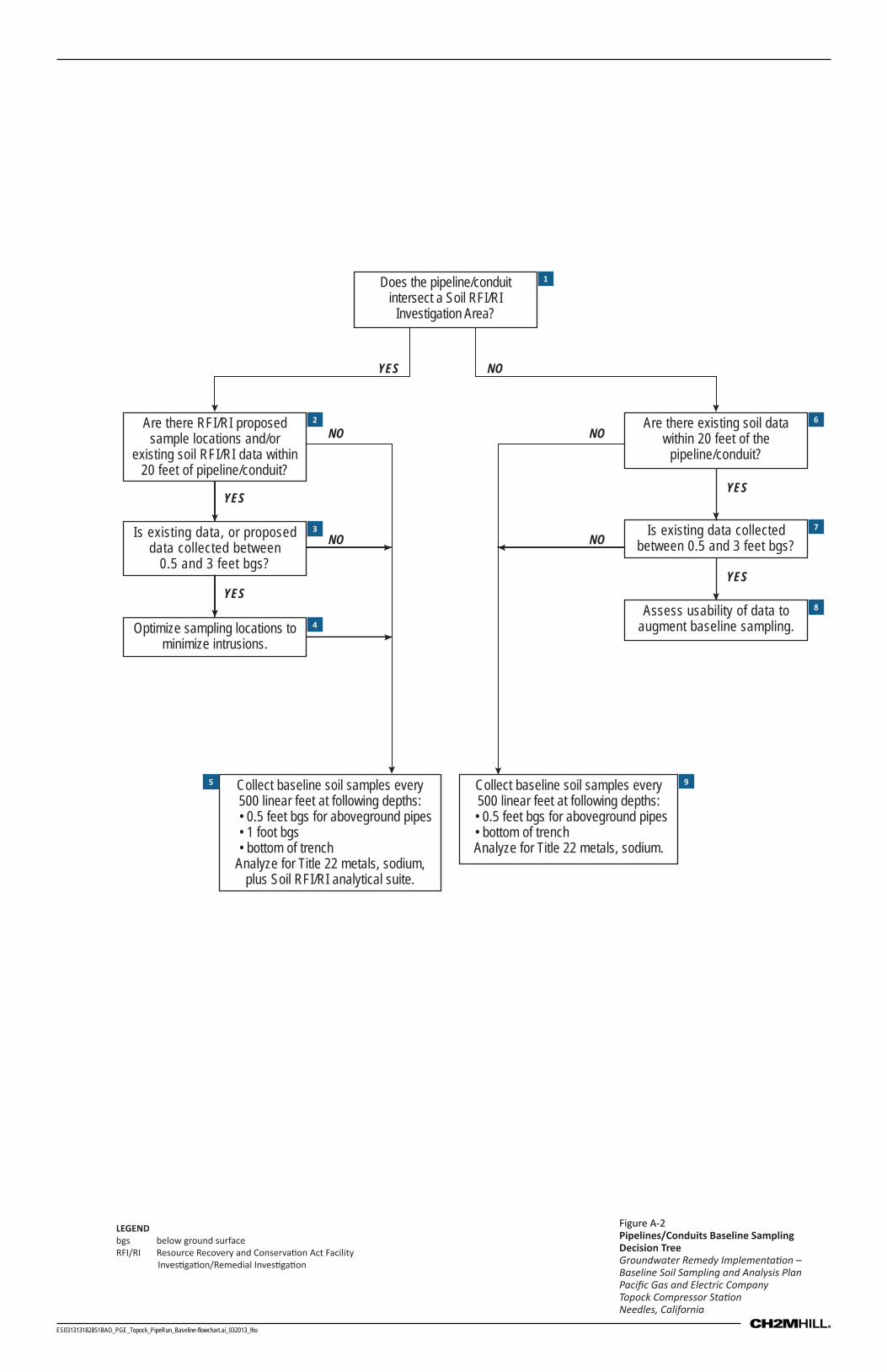
ES031313182851BAO_PGE_Topock_PipeRun_Baseline-flowchart.ai_032013_lho
Does the pipeline/conduit intersect a Soil RFI/RI
Investigation Area?
Is existing data, or proposed data collected between
0.5 and 3 feet bgs?
Collect baseline soil samples every500 linear feet at following depths:• 0.5 feet bgs for aboveground pipes• 1 foot bgs• bottom of trench
Analyze for Title 22 metals, sodium,plus Soil RFI/RI analytical suite.
Collect baseline soil samples every500 linear feet at following depths:• 0.5 feet bgs for aboveground pipes• bottom of trenchAnalyze for Title 22 metals, sodium.
Is existing data collected between 0.5 and 3 feet bgs?
YESYES
YESYES
YES NO
NO
NO
NO
NO
Assess usability of data to augment baseline sampling.
Are there existing soil data within 20 feet of the
pipeline/conduit?
Optimize sampling locations to minimize intrusions.
Are there RFI/RI proposed sample locations and/or
existing soil RFI/RI data within 20 feet of pipeline/conduit?
1
2
3
4
5 9
8
7
6
Figure A-2Pipelines/Conduits Baseline Sampling Decision Tree Groundwater Remedy Implementa on –Baseline Soil Sampling and Analysis PlanPacific Gas and Electric CompanyTopock Compressor Sta onNeedles, California
LEGENDbgs below ground surfaceRFI/RI Resource Recovery and Conserva on Act Facility
Inves ga on/Remedial Inves ga on

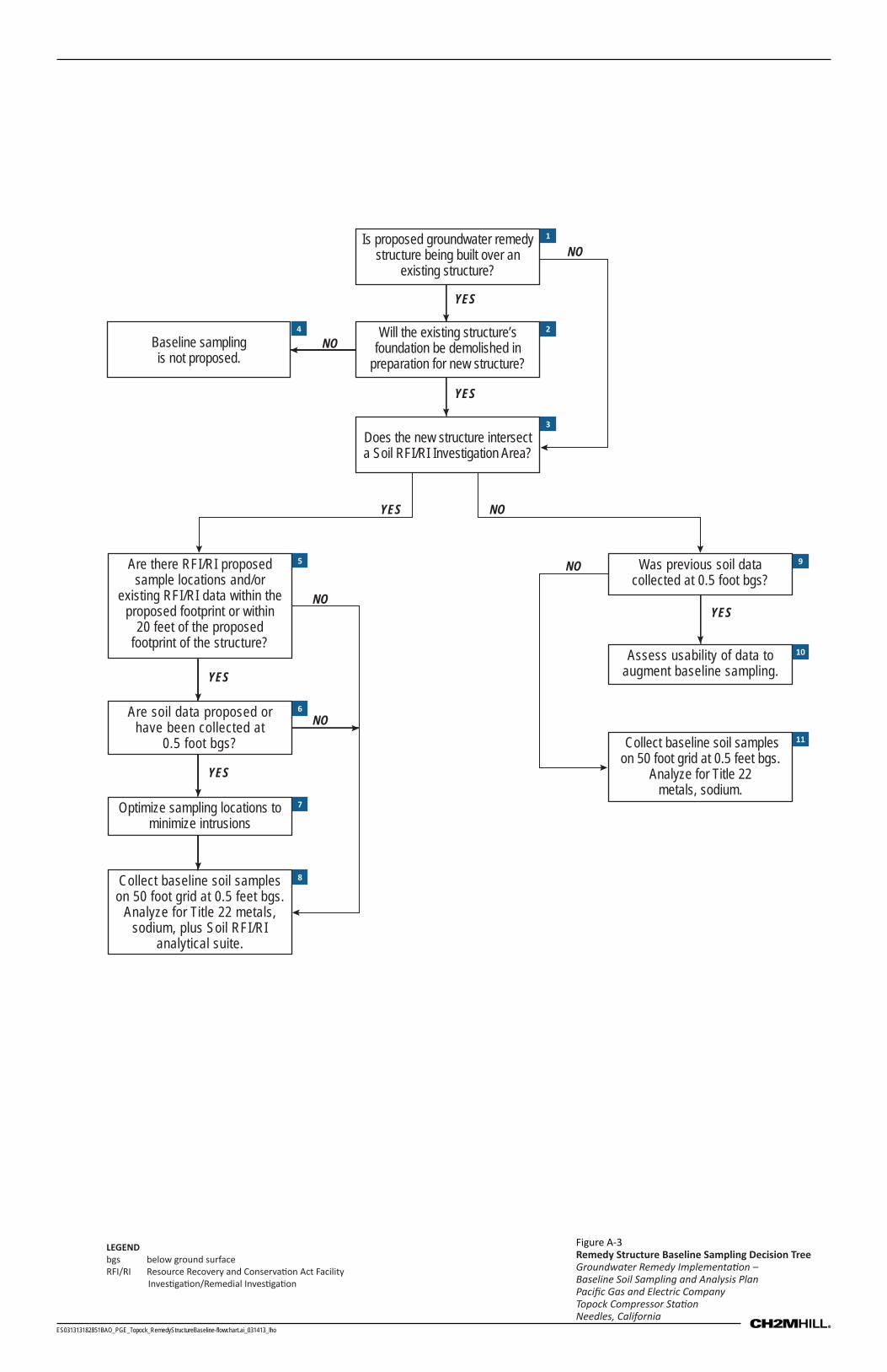
ES031313182851BAO_PGE_Topock_RemedyStructureBaseline-flowchart.ai_031413_lho
Is proposed groundwater remedy structure being built over an
existing structure?
Will the existing structure’s foundation be demolished in
preparation for new structure?
Are there RFI/RI proposed sample locations and/or
existing RFI/RI data within the proposed footprint or within
20 feet of the proposed footprint of the structure?
Are soil data proposed or have been collected at
0.5 foot bgs?
Collect baseline soil samples on 50 foot grid at 0.5 feet bgs.
Analyze for Title 22 metals, sodium, plus Soil RFI/RI
analytical suite.
Assess usability of data to augment baseline sampling.
Does the new structure intersect a Soil RFI/RI Investigation Area?
Baseline samplingis not proposed.
YES
YES
YES
YES
YES
YES
NO
NO
NO
NO
NO
NO Was previous soil data collected at 0.5 foot bgs?
Collect baseline soil samples on 50 foot grid at 0.5 feet bgs.
Analyze for Title 22metals, sodium.
Optimize sampling locations to minimize intrusions
LEGENDbgs below ground surfaceRFI/RI Resource Recovery and Conserva on Act Facility
Inves ga on/Remedial Inves ga on
Figure A-3Remedy Structure Baseline Sampling Decision TreeGroundwater Remedy Implementa on –Baseline Soil Sampling and Analysis PlanPacific Gas and Electric CompanyTopock Compressor Sta onNeedles, California
1
2
3
4
5
6
7
8
11
10
9

Attachment 1 Standard Operating Procedures (SOPs)
(Provided on CD-ROM Only)

TOPOCK FIELD PROCEDURE MANUAL
SOP-B2, REVISION 2, 12/15/06
SOP-B2
Soil Classification and Logging Procedures Standard Operating Procedures for PG&E Topock Program
This standard operating procedure (SOP) provides guidance to obtain accurate and consistent descriptions of soil characteristics during soil-sampling operations. The characterization is based on visual examination and manual tests not on laboratory determinations.
REQUIRED DOCUMENTS
1) Event-specific sampling and analysis plan, work plan or event-specific field instructions. Planned borehole depth, proposed well construction/specifications, and field sampling summary table, if available.
2) Applicable project work plan or monitoring plan. Refer to Topock Program Sampling,Analysis, and Field Procedures Manual and Quality Assurance Project Plan (Procedures Manual), as required.
3) Topock Program Health and Safety Plan (HSP).
4) Previous sampling, drilling, or well construction logs from other boreholes or wells in the vicinity, if available.
5) Blank field notebook.
6) Blank CH2M HILL soil boring log Form D1586.
PREPARATION AND SETUP
1) Review event-specific work plan or event-specific field instructions, previous sampling logs, Procedures Manual, and HSP.
2) Initiate field logbook for sampling activity.
3) Review sampling procedures and equipment, and planned sample depths with drilling contractor and field crew.
EQUIPMENT LIST
Indelible pens
Tape measure or ruler
Field logbook
Spatula
HCl, 10-percent solution
Squirt bottle/Spray bottle with water
SOP-B2_SOILCLASSIFICATIONANDLOGGINGPROCEDURES_REV1_12-14-06.DOC 1 OF 12
TOPOCK FIELD PROCEDURE MANUAL
SOP-B2, REVISION 2, 12/15/06
SOP-B2_SOILCLASSIFICATIONANDLOGGINGPROCEDURES_REV1_12-14-06.DOC 2 OF 12
Rock- or soil-color chart (e.g., Munsell)
Grain-size chart
Hand lens
Unified Soil Classification System index charts and tables to help with soil classification
PROCEDURES
This section covers several aspects of the soil characterization: instructions for completing the CH2M HILL soil boring log (see Form D1586, Attachment A) and the field logging of soil using the “Unified Soil Classification System and Logging Criteria” (Attachment B).
Instructions for Completing Soil Boring Logs
Soil boring logs will be completed on field boring log forms. Information collected will be consistent with that required for Form D1586 (attached), a standard CH2M HILL form, or an equivalent form that supplies the same information.
The information collected in the field to perform the soil characterization is described below.
Field personnel should review completed logs for accuracy, clarity, and thoroughness of detail. Samples also should be checked to see that information is correctly recorded on both jar lids and labels and on the log sheets.
Heading Information
1) Boring/Well Number. Enter the boring/well number. A numbering system should be chosen that does not conflict with information recorded for previous exploratory work done at the site. Number the sheets consecutively for each boring.
2) Location. If stationing, coordinates, mileposts, or similar project layout information is available, indicate the position of the boring to that system using modifiers such as “approximate” or “estimated,” as appropriate.
3) Elevation. Elevation will be determined at the conclusion of field activities.
4) Drilling Contractor. Enter the name of the drilling company and the city and state where the company is based.
5) Drilling Method and Equipment. Identify the bit size and type, drilling fluid (if used), and method of drilling (e.g., rotary, hollow-stem auger, sonic). Information on the drilling equipment (e.g., CME 55, Mobile B61) should be noted.
6) Water Level and Date. Enter the depth below ground surface to the apparent water level in the borehole. The information should be recorded as a comment. If free water is not encountered during drilling or cannot be detected because of the drilling method, this information should be noted. Record date and time of day (for tides, river stage) of each water level measurement.
TOPOCK FIELD PROCEDURE MANUAL
SOP-B2, REVISION 2, 12/15/06
SOP-B2_SOILCLASSIFICATIONANDLOGGINGPROCEDURES_REV1_12-14-06.DOC 3 OF 12
7) Date of Start and Finish. Enter the dates the boring was started and completed. Time of day should be added if several borings are performed on the same day.
8) Logger. Enter the first initial and full last name of the logger.
Technical Data
1) Depth Below Surface. Use a depth scale that is appropriate for the sample spacing and for the complexity of subsurface conditions.
2) Sample Interval. Note the depth at the top and bottom of the sample interval.
3) Sample Type and Number. Enter the sample type and number. SS-1 = split spoon, first sample. Number samples consecutively regardless of type. Enter a sample number even if no material was recovered in the sampler.
4) Sample Recovery. Enter the length to the nearest 0.1 foot of soil sample recovered from the sampler. Often, there will be some wash or caved material above the sample; do not include the wash material in the measurement. Record recovery in feet.
5) Soil Description. The soil classification should follow the format described in the “Field Classification of Soil” subsection below.
6) Comments. Include all pertinent observations (changes in drilling fluid color, rod drops, drilling chatter, rod bounce as in driving on a cobble, damaged Shelby tubes, and equipment malfunctions). In addition, note if casing was used, the sizes and depths installed, and if drilling fluid was added or changed. You should instruct the driller to alert you to any significant changes in drilling (changes in material, occurrence of boulders, and loss of drilling fluid). Such information should be attributed to the driller and recorded in this column. Specific information might include:
The date and the time drilling began and ended each day.
The depth and size of casing and the method of installation.
The date, time, and depth of water level measurements.
Depth of rod chatter.
Depth and percentage of drilling fluid loss.
Depth of hole caving or heaving.
Depth of change in material.
Health and safety monitoring data.
Drilling interval through a boulder.
Field Classification of Soil
This section presents the format for the field classification of soil. In general, the approach and format for classifying soils should conform to the “United Soils Classification System and Logging Criteria” (see charts and criteria, Attachment B).
TOPOCK FIELD PROCEDURE MANUAL
SOP-B2, REVISION 2, 12/15/06
SOP-B2_SOILCLASSIFICATIONANDLOGGINGPROCEDURES_REV1_12-14-06.DOC 4 OF 12
The Unified Soil Classification System (USCS) is based on numerical values of certain soil properties that are measured by laboratory tests (ASTM D 2487). It is possible, however, to estimate these values in the field with reasonable accuracy using visual-manual procedures (ASTM D 2488). In addition, some elements of a complete soil description, such as the presence of cobbles or boulders, changes in strata, and the relative proportions of soil types in a bedded deposit can be obtained only in the field.
Soil descriptions should be precise and comprehensive without being verbose. The correct overall impression of the soil should not be distorted by excessive emphasis on insignificant details. In general, similarities rather than differences between consecutive samples should be stressed.
Soil Descriptions
Soil descriptions must be recorded for every soil sample collected. The format and order for soil descriptions should be:
1) Soil name (synonymous with ASTM D 2488 Group Name) with appropriate modifiers. Soil name should be in all capitals in the log, for example “POORLY-GRADED SAND.”
2) Group symbol, in parentheses, for example, “(SP).”
3) Color, using Munsell color designation.
4) Particle size distribution (i.e., sand, silt, clay).
5) Moisture content.
6) Relative density or consistency.
7) Soil structure, mineralogy, or other descriptors.
This order follows, in general, the format described in ASTM D 2488.
(1) Soil Name
The basic name of a soil should be the ASTM D 2488 Group Name on the basis of visual estimates of gradation and plasticity. The soil name should be capitalized.
Examples of acceptable soil names are illustrated by the following descriptions:
A soil sample is visually estimated to contain 15-percent gravel, 55-percent sand, and 30-percent fines (passing No. 200 sieve). The fines are estimated as either low- or highly-plastic silt. This visual classification is SILTY SAND WITH GRAVEL with a Group Symbol of (SM).
Another soil sample has the following visual estimate: 10-percent gravel, 30-percent sand, and 60-percent fines (passing the No. 200 sieve). The fines are estimated as low-plastic silt. This visual classification is SANDY SILT. The gravel portion is not included in the soil name because the gravel portion was estimated as less than 15 percent. The Group Symbol is (ML).
The gradation of coarse-grained soil (more than 50 percent retained on No. 200 sieve) is included in the specific soil name in accordance with ASTM D 2488.
TOPOCK FIELD PROCEDURE MANUAL
SOP-B2, REVISION 2, 12/15/06
SOP-B2_SOILCLASSIFICATIONANDLOGGINGPROCEDURES_REV1_12-14-06.DOC 5 OF 12
There is no need to further document the gradation.
However, the maximum size and angularity or roundness of gravel and sand-sized particles should be recorded.
For fine-grained soil (50 percent or more passing the No. 200 sieve), the name is modified by the appropriate plasticity/elasticity term in accordance with ASTM D 2488.
Interlayered soil should each be described starting with the predominant type.
An introductory name, such as “Interlayered Sand and Silt,” should be used.
In addition, the relative proportion of each soil type should be indicated (see Table 1 for example).
Where helpful, the evaluation of plasticity/elasticity can be justified by describing results from any of the visual-manual procedures for identifying fine-grained soils, such as reaction to shaking, toughness of a soil thread, or dry strength as described in ASTM D 2488.
(2) Group Symbol
The appropriate group symbol from ASTM D 2488 must be given after each soil name.
1) The group symbol should be placed in parentheses to indicate that the classification has been estimated.
2) In accordance with ASTM D 2488, dual symbols (e.g., GP-GM or SW-SC) can be used to indicate that a soil is estimated to have about 10-percent fines.
3) Borderline symbols (e.g., GM/SM or SW/SP) can be used to indicate that a soil sample has been identified as having properties that do not distinctly place the soil into a specific group. Generally, the group name assigned to a soil with a borderline symbol should be the group name for the first symbol. The use of a borderline symbol should not be used indiscriminately. Every effort should be made to first place the soil into a single group.
(3) Color
Soil color is described by comparing the sample with the Munsell Soil Color Charts. The Munsell colors should be used unless directed otherwise by project sampling plans. Instructions for their proper use are in the color charts. The color name shall precede the Munsell color notation (e.g., “yellowish brown, 10 YR 5/4”), with color hue and chroma number parenthetically entered in the borelog description. If no color chip is available, the color should be simply described as primary color (i.e., green, brown, gray, yellow, tan, etc.).
(4) Particle Size Distribution
Within the gravel sizes and the sand sizes, there are further divisions based on particle sizes. Gravel is divided into fine and coarse gravel. Fine-gravel particles (pebbles) are those that would pass through 3/4-inch opening but not a 1/4-inch opening. The fine gravel ranges from pea- to marble-sized. Coarse-gravel particles are those that would pass through a 3-inch opening but not a 3/4-in opening. Common objects of this size are grapes and tennis balls. Cobbles range from 3 inches to 12 inches in size; boulders are larger than 12 inches.
TOPOCK FIELD PROCEDURE MANUAL
SOP-B2, REVISION 2, 12/15/06
SOP-B2_SOILCLASSIFICATIONANDLOGGINGPROCEDURES_REV1_12-14-06.DOC 6 OF 12
Sand is divided into three sizes: fine, medium, and coarse. Sand passes a No. 4 sieve (approximately 1/4 inch) and is retained in a No. 200 sieve (0.003 inch). Fine-sand particles pass a No. 40 sieve (approximately 1/64 inch) and are retained in the No. 200 (0.003 inch) sieve. These particles are sugar- or table salt-sized. Medium sand passes the No. 10 sieve (approximately 1/2 inch) and retained on the No. 40 sieve. These particles are about the same size as the openings in window screening. Coarse-sand particles would pass a No. 4 sieve (approximately 1/4 inch) and be retained on a No. 10 sieve. Rock salt granules fall in this size range. Sand and gravel particle sizes are illustrated in ASTM D2488 along with percentage estimating charts. The percentages of different grain size fractions are important in the soil type determination.
(5) Moisture Content
Soil moisture content shall be estimated using only the terminology described below:
Dry - Absence of moisture, dusty, dry to the touch
Moist - Damp but no visible water
Wet - Visibly free water, usually sampled from below the water table
(6) Relative Density or Consistency
An estimate of the consistency shall accompany descriptions of all fine-grained soil (silt and clay where more than 50 percent of the material would pass the No. 200 sieve). A pocket penetrometer is the most accurate method for estimating the consistency of fine-grained soils. The table below lists characteristics for soil consistency identification.
Consistency
Unconfined
Compressive
Strength (tons/ft)a
Blows/foot
(SPT)b
Manual Procedure
Very soft <0.25 0 – 4 Thumb will penetrate soil more than 1 inch (25 mm).
Soft 0.25 - 0.50 4 – 8 Thumb will penetrate soil about 1 inch (25 mm).
Firm(formerly stiff)
-1.50 8 – 15 Thumb will indent soil about 1/4 inch (6 mm).
Hard -2.00 15 – 30 Thumb will not indent soil but readily indented with thumbnail.
Very hard >4.0 > 30 Thumbnail will not indent soil.
Notes:a Pocket penetrometer
b Blows/foot is defined as the total number of blows required to drive the second and third 6 inches of penetration
(blow counts for the first 6 inches are also noted) while driving an 18-inch SPT sampler with a 140-pound hammer falling a free height of 30 inches. Conversion factors may be applied when the field log information is transferred to the final log when using a sampler other than an SPT (Standard penetrometer ) (e.g., S&H or Modified California), or when using different hammer weights and drop. The conversion factor is approximately 0.5 for an S&H sampler with a hammer weight of 140 pounds falling 30 inches.
Descriptions of all coarse-grained soil (sand and gravel where less than 50 percent of the material would pass the No. 200 sieve and 100 percent would pass the 3-inch sieve) shall be
TOPOCK FIELD PROCEDURE MANUAL
SOP-B2, REVISION 2, 12/15/06
SOP-B2_SOILCLASSIFICATIONANDLOGGINGPROCEDURES_REV1_12-14-06.DOC 7 OF 12
accompanied by an estimate of the density based upon standard penetrometer (SPT) blow counts. The following terminology should be used:
Density Blows/foot (SPT)
Very loose < 4
Loose 4-10
Medium dense 10-30
Dense 30-50
Very dense > 50
(7) Soil Structure, Mineralogy, and Other Descriptors
Discontinuities and inclusions are important and should be described. Such features include joints or fissures, slickensides, bedding or laminations, veins, root holes, and wood debris.
Significant mineralogical information such as cementation, abundant mica, or unusual mineralogy should be described.
Other descriptors may include particle angularity or shape, maximum particle size, hardness of large particles, plasticity of fines, dry strength, dilatancy, toughness, reaction to HCl, and staining, as well as other information such as organic debris, odor, or presence of free product. Criteria for the use of these other descriptions include:
Structure:
Stratified - Alternating layers of varying material or color with layers at least 1/4-inch thick; note thickness.
Laminated - Alternating layers of varying material or color with the layers less than 1/4-inch thick; note thickness.
Fissured - Breaks along definite planes of fracture with little resistance.
Slickensides - Fracture planes appear polished or glossy, often striated.
Blocky - Cohesive soil that can be broken down into small angular lumps that resist further breakdown.
Lensed - Inclusion of small pockets of different soils, such as lenses of sand within clay; note thickness.
Homogeneous - Same color and appearance throughout.
Grading - Whether the particles increase or decrease in size toward the top of logged interval.
Particle Shape:
Flat - Particles with width/thickness ratio > 3.
Elongated - Particles with length/width ratio > 3.
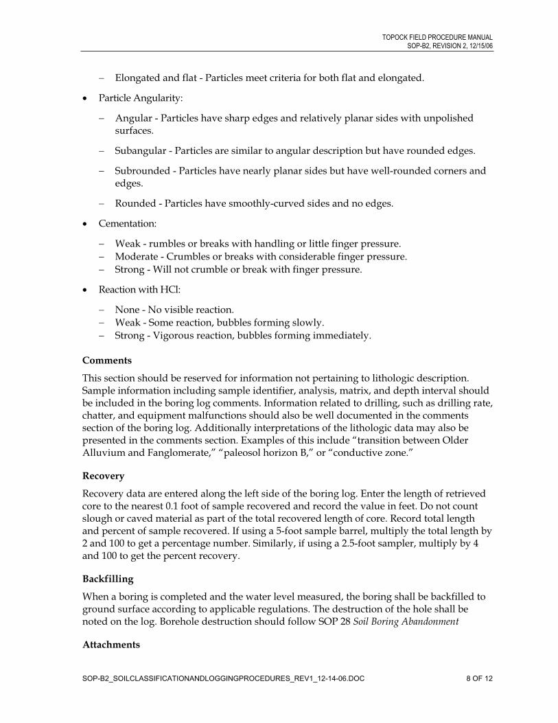
TOPOCK FIELD PROCEDURE MANUAL
SOP-B2, REVISION 2, 12/15/06
SOP-B2_SOILCLASSIFICATIONANDLOGGINGPROCEDURES_REV1_12-14-06.DOC 8 OF 12
Elongated and flat - Particles meet criteria for both flat and elongated.
Particle Angularity:
Angular - Particles have sharp edges and relatively planar sides with unpolished surfaces.
Subangular - Particles are similar to angular description but have rounded edges.
Subrounded - Particles have nearly planar sides but have well-rounded corners and edges.
Rounded - Particles have smoothly-curved sides and no edges.
Cementation:
Weak - rumbles or breaks with handling or little finger pressure.
Moderate - Crumbles or breaks with considerable finger pressure.
Strong - Will not crumble or break with finger pressure.
Reaction with HCl:
None - No visible reaction.
Weak - Some reaction, bubbles forming slowly.
Strong - Vigorous reaction, bubbles forming immediately.
Comments
This section should be reserved for information not pertaining to lithologic description. Sample information including sample identifier, analysis, matrix, and depth interval should be included in the boring log comments. Information related to drilling, such as drilling rate, chatter, and equipment malfunctions should also be well documented in the comments section of the boring log. Additionally interpretations of the lithologic data may also be presented in the comments section. Examples of this include “transition between Older Alluvium and Fanglomerate,” “paleosol horizon B,” or “conductive zone.”
Recovery
Recovery data are entered along the left side of the boring log. Enter the length of retrieved core to the nearest 0.1 foot of sample recovered and record the value in feet. Do not count slough or caved material as part of the total recovered length of core. Record total length and percent of sample recovered. If using a 5-foot sample barrel, multiply the total length by 2 and 100 to get a percentage number. Similarly, if using a 2.5-foot sampler, multiply by 4 and 100 to get the percent recovery.
Backfilling
When a boring is completed and the water level measured, the boring shall be backfilled to ground surface according to applicable regulations. The destruction of the hole shall be noted on the log. Borehole destruction should follow SOP 28 Soil Boring Abandonment
Attachments
TOPOCK FIELD PROCEDURE MANUAL
SOP-B2, REVISION 2, 12/15/06
Soil Boring Log, CH2M HILL Form D1586, and a completed example
Unified Soil Classification System and Logging Criteria
Key Checks and Preventive Maintenance
Check entries to the soil boring log and field logbook in the field; because the samples will be disposed of, confirmation and corrections cannot be made later. Check that sample numbers and intervals are properly specified. Check that drilling and sampling equipment is decontaminated using the procedures defined in SOP Decontamination of Drilling Rigs and Equipment.
SOP-B2_SOILCLASSIFICATIONANDLOGGINGPROCEDURES_REV1_12-14-06.DOC 9 OF 12


ATTACHMENT A
Examples of Soil Bore Logs

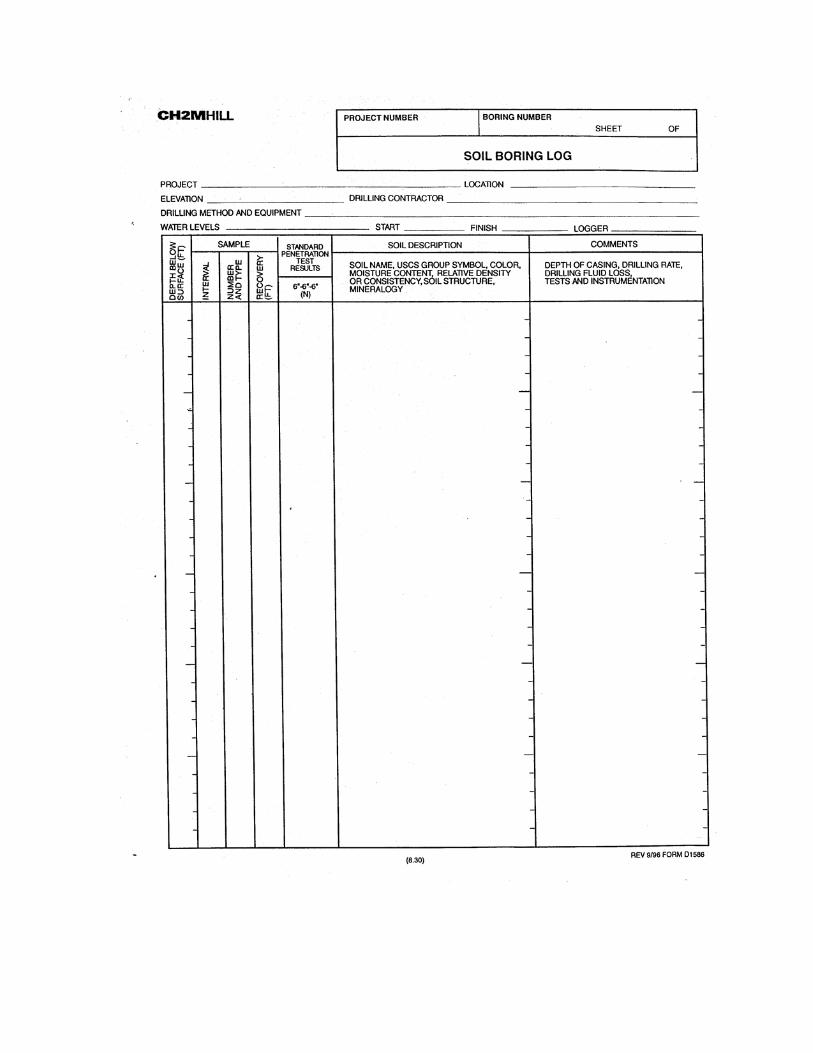

10
- 65% sand, 30% gravel up to 4cm, 5% fines
SW
6
SW
16
- fine roots, iron staining, some iron oxide coating on grains
- slightly moist
- dry
DATE COMPLETED:
- one subrnd chert gravel
DATE STARTED:
- lt grey (10YR7/2), subang to rnd met gravel up to 9cm, 2% to 5%
fines
- dk yellowish brn (10YR4/4), mostly c sand subang to ang, met,
some Miocene conglomerate gravel
USCSCODE
MW-47
5
10
15
20
25
30
35
DRILLING OBSERVATIONS AND OPERATIONS,DAILY START AND END TIMES , DRILL RATE,REFUSALS, SAMPLING AND TESTING NOTES.
SOIL NAME, USCS SYMBOL, COLOR,PERCENT COMPOSITION, GRADING, GRAIN SHAPE, MINERALOGY,
DENSITY/CONSISTENCY, STRUCTURE, MOISTURE.
PROJECT NUMBER:
COMMENTS
TY
PE
/N
UM
BE
R
SAMPLE
SW
- Possible Fluvially Reworked Alluvium
POORLY GRADED SAND (SP) - very lt brn (10YR7/3), =2% fines, 98%
f to m lithic quartz sand, subang to subrnd, dry
WELL GRADED SAND w/ GRAVEL (SW) - lt yellowish brn (10YR6/4),
45% gravel up to 7cm, 50% f to m sand, 5% fines, loose, met subang
gravel, dry(moist@ 17')
WELL GRADED SAND w/ GRAVEL (SW) - dk yellowish brn (10YR3/6),
35% gravel up to 4cm, 55% m to c sand, 10% silty fines, met clasts are
grain supported
WELL GRADED SAND w/ GRAVEL AND CLAY (SW) - dk yellowish brn
(10YR3/6), 30% subang met gravel up to 7 cm, 55% subrnd to subang
m to c sand, 15% clayey fines, m density, moist
Hand augured to 5' bgs
Rapid drill rate, no chatter
Drill rate slowed to clean out 8" pipe
SP
- cobble present in slough
Prosonic Corp. Phoenix, AZ
7,615,629.49 03/13/2006IN
TE
RV
AL
SOIL BORING LOG - DRAFT FOR DISCUSSION
02/27/2006
HOLE DEPTH (ft):
Sonic AT (track mounted)
RE
CO
VE
RY
(ft)
DEPTH BGS(feet)
BORING NUMBER:SHEET 1 of 9
288.0
DRILLING EQUIPMENT:
SURFACE ELEVATION:2,103,450.05
DRILLING METHOD:Rotosonic
IMPM Drill Program
LOGGED BY:
SOIL DESCRIPTION
PG&E Compressor Station - Flood Plain, Topock, California
326128.01.16.EN
B. Moayyad, K. Ebel
482.6 ft. MSLEASTING (CCS NAD 27 Z 5):NORTHING (CCS NAD 27 Z 5):
- some oxide staining
PROJECT NAME:
some mm siltstone
LOCATION:
DRILLING CONTRACTOR:
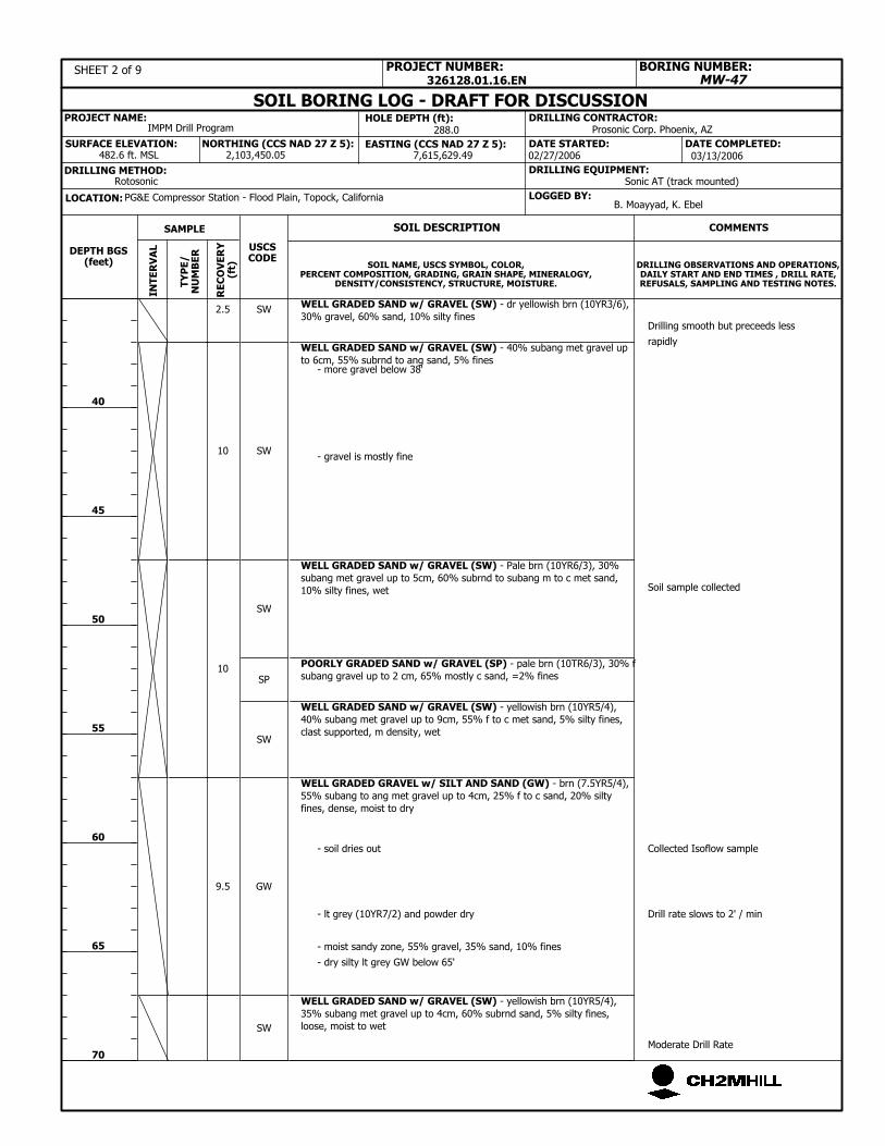
SW
SW
GW
SP
SW
SW
Moderate Drill Rate
Drill rate slows to 2' / min
Collected Isoflow sample
Soil sample collected
SW
482.6 ft. MSL
B. Moayyad, K. Ebel
NORTHING (CCS NAD 27 Z 5):
326128.01.16.EN
LOCATION:
Drilling smooth but preceeds less
rapidly
DRILLING CONTRACTOR:IMPM Drill Program
LOGGED BY:
SOIL DESCRIPTION
PROJECT NAME:
WELL GRADED SAND w/ GRAVEL (SW) - yellowish brn (10YR5/4),
40% subang met gravel up to 9cm, 55% f to c met sand, 5% silty fines,
clast supported, m density, wet
WELL GRADED GRAVEL w/ SILT AND SAND (GW) - brn (7.5YR5/4),
55% subang to ang met gravel up to 4cm, 25% f to c sand, 20% silty
fines, dense, moist to dry
POORLY GRADED SAND w/ GRAVEL (SP) - pale brn (10TR6/3), 30% f
subang gravel up to 2 cm, 65% mostly c sand, =2% fines
WELL GRADED SAND w/ GRAVEL (SW) - Pale brn (10YR6/3), 30%
subang met gravel up to 5cm, 60% subrnd to subang m to c met sand,
10% silty fines, wet
WELL GRADED SAND w/ GRAVEL (SW) - 40% subang met gravel up
to 6cm, 55% subrnd to ang sand, 5% fines
WELL GRADED SAND w/ GRAVEL (SW) - dr yellowish brn (10YR3/6),
30% gravel, 60% sand, 10% silty fines
WELL GRADED SAND w/ GRAVEL (SW) - yellowish brn (10YR5/4),
35% subang met gravel up to 4cm, 60% subrnd sand, 5% silty fines,
loose, moist to wet
2,103,450.05
DRILLING EQUIPMENT:
Prosonic Corp. Phoenix, AZ
SURFACE ELEVATION:
DRILLING METHOD:Rotosonic Sonic AT (track mounted)
02/27/2006
40
45
50
55
60
65
70
SAMPLE
TY
PE
/N
UM
BE
R
COMMENTS
PROJECT NUMBER:
DRILLING OBSERVATIONS AND OPERATIONS,DAILY START AND END TIMES , DRILL RATE,REFUSALS, SAMPLING AND TESTING NOTES.
MW-47
USCSCODE
DATE COMPLETED:DATE STARTED:7,615,629.49
SOIL NAME, USCS SYMBOL, COLOR,PERCENT COMPOSITION, GRADING, GRAIN SHAPE, MINERALOGY,
DENSITY/CONSISTENCY, STRUCTURE, MOISTURE.
10
- gravel is mostly fine
- more gravel below 38'
288.0
9.5
- moist sandy zone, 55% gravel, 35% sand, 10% fines
10
2.5
03/13/2006IN
TE
RV
AL
SOIL BORING LOG - DRAFT FOR DISCUSSION
SHEET 2 of 9
HOLE DEPTH (ft):
- soil dries out
- lt grey (10YR7/2) and powder dry
DEPTH BGS(feet)
BORING NUMBER:
PG&E Compressor Station - Flood Plain, Topock, California
- dry silty lt grey GW below 65'
EASTING (CCS NAD 27 Z 5):
RE
CO
VE
RY
(ft)

SM
5.5
4
4
2
2
4
5
3
6
SW
SAND w/ GRAVEL (SW) - dk reddish brn (5YR3/4), 20% subang to
subrnd gravel up to 5cm, 75% f to c sand, 5% fines, well graded, loose,
met, wet
SILTY SAND (SW) - mottled dk reddish brn (5YR3/4), 10% subang to
subrnd gravel up to 2.5cm, 50% well graded f to m sand, 40% silt,
metamorphic, dry to damp, no odor, interbedded sandy silt laminations
SILTY SAND W/ GRAVEL (SM) - brn (7.5YR4/4), 25% subang to
subrnd gravel up to 6.5cm, 60% m to c sand, 15% silty fines, well
graded, m consolidated, met, wet, no odor
SILTY SAND w/ GRAVEL (SM) - dk yellowish brn (10YR4/4), 15%
subang to subrnd up to 2.5cm met gravel, 75% well graded f to c sand,
10% fines, mostly met, trace chert, loose, wet, no odor
SILTY SAND (SM) - brn (7.5YR4/4), 5% ang to subrnd met gravel up
to 1.5cm increasing with depth, 85% poorly graded m to c sand, 10%
fines, loose, wet
WELL GRADED SAND w/ SILT AND SAND (SW) - dr yellowish brn
(10YR4/4), 10% subang to subrnd up to 3cm met gravel, 75%well
graded f to c sand, 15% fines, moist to wet
SILTY SAND w/ GRAVEL (SM) - dk yellowish brn (10YR4/4), 25%
subang to subrnd up to 4cm met gravel, 60% well graded f to c sand,
15% fines, wet, no odor
POORLY GRADED SAND w/ SILT (SP) - brn (7.5YR4/4), 5% subrnd to
subang met gravel up to 4cm, 85% f to c sand, 10% fines, poorly
graded, wet, no odor
SILTY SAND W/ GRAVEL (SM) - brn (7.5YR4/4), 20% subang to
subrnd gravel up to 6cm, 60% f to c sand, 20% silty fines, well graded,
m consolidated, met, wet, no odor
SW
SM
SM
SW
SW
SM
SM
SP
SILTY SAND w/ GRAVEL (SM) - brn (7.5YR4/4), 15% subang to
subrnd gravel, 70% f to m sand, 15% fines, poorly graded,
met,increasingly consolidated, slightly to moderately calcareous, moist
to wet
Collected Isoflow sample
Drill rate = 0.75' to 1.5' / min
Rotosonic Sonic AT (track mounted)
02/27/2006
288.0 Prosonic Corp. Phoenix, AZ
7,615,629.49 03/13/2006IN
TE
RV
AL
SOIL BORING LOG - DRAFT FOR DISCUSSIONHOLE DEPTH (ft):
SURFACE ELEVATION:
RE
CO
VE
RY
(ft)
DEPTH BGS(feet)
BORING NUMBER:
PG&E Compressor Station - Flood Plain, Topock, CaliforniaLOCATION:
SHEET 5 of 9
DATE STARTED:
SAMPLE
TY
PE
/N
UM
BE
R
COMMENTS
PROJECT NUMBER:
SOIL NAME, USCS SYMBOL, COLOR,PERCENT COMPOSITION, GRADING, GRAIN SHAPE, MINERALOGY,
DENSITY/CONSISTENCY, STRUCTURE, MOISTURE.
DRILLING OBSERVATIONS AND OPERATIONS,DAILY START AND END TIMES , DRILL RATE,REFUSALS, SAMPLING AND TESTING NOTES.
145
150
155
160
165
170
175
MW-47
DRILLING METHOD:
DATE COMPLETED:2,103,450.05
DRILLING EQUIPMENT:
PROJECT NAME:
USCSCODE
B. Moayyad, K. EbelLOGGED BY:
482.6 ft. MSL
IMPM Drill Program
EASTING (CCS NAD 27 Z 5):
2.5
NORTHING (CCS NAD 27 Z 5):
326128.01.16.EN
SOIL DESCRIPTION
DRILLING CONTRACTOR:

LOCATION:
DRILLING CONTRACTOR:
326128.01.16.EN
PROJECT NAME:
LOGGED BY:
SOIL DESCRIPTION
PG&E Compressor Station - Flood Plain, Topock, California
BORING NUMBER:
DEPTH BGS(feet)
MIOCENE CONGLOMERATE BEDROCK (BR) - 60% well graded
subang to rnd gravel up to 10cm, 30% well graded sand, 10% fines,
very calcareous, well consolidated to mostly hard, mod to very altered
locally, mostly met, dry to moist
EASTING (CCS NAD 27 Z 5):
ABBREVIATIONS
cc = continuous core run
brn = brown
lt = light
dk = dark
vf = very fine-grained
f = fine-grained
m = medium-grained
c = coarse-grained
vc = very coarse-grained
ang = angular
subang = subangular
subrnd = subrounded
rnd = rounded
br = bedrock formation
ss = sandstone
conglom = conglomerate
comptd = compacted
qtz = quartz
BR
Boring Terminated at 288 ft
IMPM Drill Program
NORTHING (CCS NAD 27 Z 5):
RE
CO
VE
RY
(ft)
482.6 ft. MSL
B. Moayyad, K. Ebel
0
285
DATE STARTED: DATE COMPLETED:
MW-47
DRILLING OBSERVATIONS AND OPERATIONS,DAILY START AND END TIMES , DRILL RATE,REFUSALS, SAMPLING AND TESTING NOTES.
SOIL NAME, USCS SYMBOL, COLOR,PERCENT COMPOSITION, GRADING, GRAIN SHAPE, MINERALOGY,
DENSITY/CONSISTENCY, STRUCTURE, MOISTURE.
PROJECT NUMBER:
COMMENTS
TY
PE
/N
UM
BE
R
SAMPLE
USCSCODE
02/27/2006
HOLE DEPTH (ft):
SHEET 9 of 9
SOIL BORING LOG - DRAFT FOR DISCUSSION
INT
ER
VA
L03/13/20067,615,629.49
288.0
Sonic AT (track mounted)RotosonicDRILLING METHOD:
2,103,450.05SURFACE ELEVATION:
DRILLING EQUIPMENT:
Prosonic Corp. Phoenix, AZ


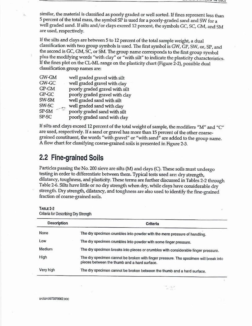
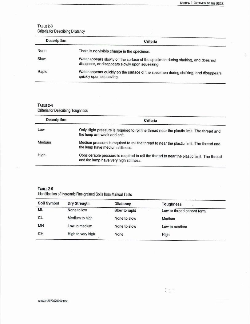

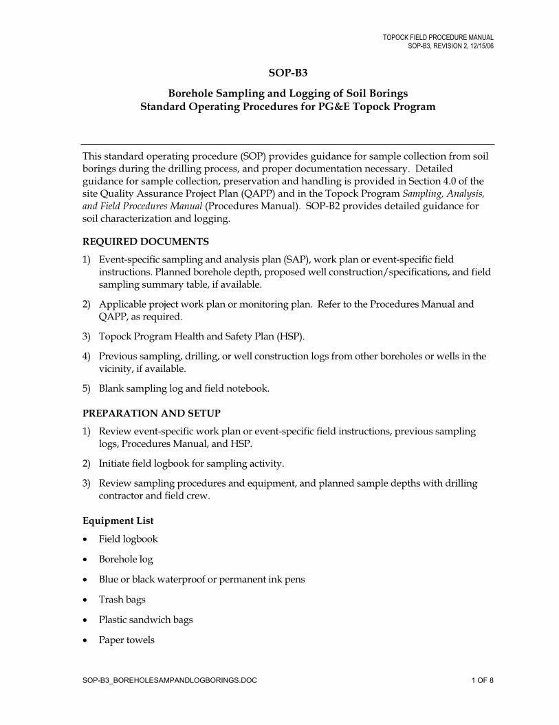
TOPOCK FIELD PROCEDURE MANUAL
SOP-B3, REVISION 2, 12/15/06
SOP-B3
Borehole Sampling and Logging of Soil Borings Standard Operating Procedures for PG&E Topock Program
This standard operating procedure (SOP) provides guidance for sample collection from soil borings during the drilling process, and proper documentation necessary. Detailed guidance for sample collection, preservation and handling is provided in Section 4.0 of the site Quality Assurance Project Plan (QAPP) and in the Topock Program Sampling, Analysis, and Field Procedures Manual (Procedures Manual). SOP-B2 provides detailed guidance for soil characterization and logging.
REQUIRED DOCUMENTS
1) Event-specific sampling and analysis plan (SAP), work plan or event-specific field instructions. Planned borehole depth, proposed well construction/specifications, and field sampling summary table, if available.
2) Applicable project work plan or monitoring plan. Refer to the Procedures Manual and QAPP, as required.
3) Topock Program Health and Safety Plan (HSP).
4) Previous sampling, drilling, or well construction logs from other boreholes or wells in the vicinity, if available.
5) Blank sampling log and field notebook.
PREPARATION AND SETUP
1) Review event-specific work plan or event-specific field instructions, previous sampling logs, Procedures Manual, and HSP.
2) Initiate field logbook for sampling activity.
3) Review sampling procedures and equipment, and planned sample depths with drilling contractor and field crew.
Equipment List
Field logbook
Borehole log
Blue or black waterproof or permanent ink pens
Trash bags
Plastic sandwich bags
Paper towels
SOP-B3_BOREHOLESAMPANDLOGBORINGS.DOC 1 OF 8
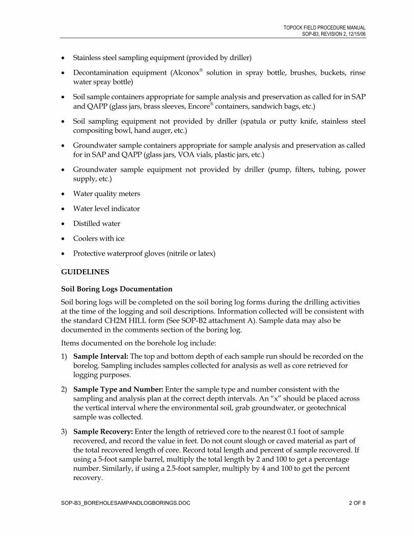
TOPOCK FIELD PROCEDURE MANUAL
SOP-B3, REVISION 2, 12/15/06
SOP-B3_BOREHOLESAMPANDLOGBORINGS.DOC 2 OF 8
Stainless steel sampling equipment (provided by driller)
Decontamination equipment (Alconox solution in spray bottle, brushes, buckets, rinse water spray bottle)
Soil sample containers appropriate for sample analysis and preservation as called for in SAP
and QAPP (glass jars, brass sleeves, Encore containers, sandwich bags, etc.)
Soil sampling equipment not provided by driller (spatula or putty knife, stainless steel compositing bowl, hand auger, etc.)
Groundwater sample containers appropriate for sample analysis and preservation as called for in SAP and QAPP (glass jars, VOA vials, plastic jars, etc.)
Groundwater sample equipment not provided by driller (pump, filters, tubing, power supply, etc.)
Water quality meters
Water level indicator
Distilled water
Coolers with ice
Protective waterproof gloves (nitrile or latex)
GUIDELINES
Soil Boring Logs Documentation
Soil boring logs will be completed on the soil boring log forms during the drilling activities at the time of the logging and soil descriptions. Information collected will be consistent with the standard CH2M HILL form (See SOP-B2 attachment A). Sample data may also be documented in the comments section of the boring log.
Items documented on the borehole log include:
1) Sample Interval: The top and bottom depth of each sample run should be recorded on the borelog. Sampling includes samples collected for analysis as well as core retrieved for logging purposes.
2) Sample Type and Number: Enter the sample type and number consistent with the sampling and analysis plan at the correct depth intervals. An “x” should be placed across the vertical interval where the environmental soil, grab groundwater, or geotechnical sample was collected.
3) Sample Recovery: Enter the length of retrieved core to the nearest 0.1 foot of sample recovered, and record the value in feet. Do not count slough or caved material as part of the total recovered length of core. Record total length and percent of sample recovered. If using a 5-foot sample barrel, multiply the total length by 2 and 100 to get a percentage number. Similarly, if using a 2.5-foot sampler, multiply by 4 and 100 to get the percent recovery.
TOPOCK FIELD PROCEDURE MANUAL
SOP-B3, REVISION 2, 12/15/06
SOP-B3_BOREHOLESAMPANDLOGBORINGS.DOC 3 OF 8
4) Sampling: Sampling difficulties shall be noted. Disturbed samples shall be noted on the log as well as the sample recovery. The top of the sample shall be marked on the container.
5) Water Levels: Water-level measurements, where groundwater is encountered, are required for each boring. Changes in soil moisture shall be noted and, if there is no water encountered, a note to that effect shall be included on the borehole log. The date and time of water-level measurements shall be documented.
At a minimum, sample identifiers (IDs) should be noted on boring logs at the depth collected. When time and space allows, a summary of analytical sample information can be included. When inclusion of these data prevents documentation of drilling information, sample data should be omitted in order to document drilling.
Borehole Sampling by Drilling—General Procedure
Split-spoon sampling procedures shall be executed in accordance with American Society for Testing and Materials (ASTM) D1586, “Standard Method for Penetration Test and Split-barrel Sampling of Soils” (ASTM 1984). California (2-inch) or Modified California (2.5-inch) split-barrel samplers may also be used.
1) The split-spoon or split-barrel sampler shall be advanced to the top of the sampling interval using a wire-line or sample rods such as A or AW. The larger-diameter samplers may be fitted with three 6-inch-long stainless-steel sleeves. The sampler shall be driven 18 inches or to refusal, with a 140-pound hammer dropping repeatedly 30 inches. Refusal shall be defined as requiring 50 blows with the hammer to advance the sampler less than 6 inches.
2) The number of blows required to drive the sampler each 6 inches shall be recorded on the borelog.
3) As the sample tubes are disassembled, an organic vapor monitor probe shall be inserted into the gap between two sample liners, and the liner exhibiting the highest reading shall be selected for analysis.
4) In general, the middle liner is collected for laboratory analysis, and 10 percent of the bottom liners are collected for quality assurance testing. A sample of the soil in the top liner typically is placed in a re-sealable plastic bag or 8-ounce clear glass jar and left in the sun for approximately 15 minutes to allow any volatile organic compounds (VOC) to volatilize.
5) After the 15 minute volatilization period, the soil vapor in the plastic bag is then measured for VOCs by taking a reading of the headspace. Background VOCs for the bag are determined by monitoring the air in an empty bag.
6) Results of the organic vapor monitoring are recorded on the boring log.
7) Small portions of soil at the ends of the sleeve are scraped off for classification.
TOPOCK FIELD PROCEDURE MANUAL
SOP-B3, REVISION 2, 12/15/06
SOP-B3_BOREHOLESAMPANDLOGBORINGS.DOC 4 OF 8
Borehole Sampling by Drilling—Split Spoon Sampling
1) Samples collected for laboratory analysis using split spoon sampling device will be separated and transferred from the split-spoon halves into sample jars by clean stainless-steel utensils.
2) Samples for VOCs will be separated and collected first, followed by semivolatile organic compounds samples.
3) For VOC samples, avoid mixing the soil before sampling and sample directly from the split spoon. See SOPs for guidance on homogenizing soil samples and for VOC sampling using EnCore samplers, respectively.
Borehole Sampling by Drilling—Direct-push Sampling
1) Samples collected for laboratory analysis using a direct-push sampling drill rig will be handled by either opening the tube and placing the soil in sample jars or cutting the acetate tube and submitting it the laboratory directly.
2) For samples that will be removed from the acetate tube, the tube will be cut open longitudinally using a double-bladed razor knife.
Soil will be inspected and logged prior to removal of soil samples.
A short section of soil will be removed from the acetate sleeve using a stainless-steel utensil, homogenized in a clean stainless-steel bowl, and placed in sample jars.
Soil collected for VOC analysis will be sampled directly from the split acetate sleeve using EnCore samplers.
3) Alternatively, a short (6-inch) length of liner will be cut from the acetate sleeve and collected directly for laboratory analysis.
The section of acetate liner will be removed, capped with Teflon sheeting and plastic end caps at both ends, and taped with clear label or packing tape.
Labels shall be affixed to the liners with job designation, time, boring number, sample depth interval, sample number, date sampled, and the initials of the sampler clearly marked.
The samples shall then be enclosed in a plastic bag and stored in a cooler maintained at 4°C.
Sample information shall be placed on the chain-of-custody, the borelog, and the field logbook. All samples shall be handled in accordance with Chain of Custody Procedures.
Borehole Sampling by Drilling—Split-barrel Sampling
Soil samples can also be collected using a 3-foot-long or 5-foot-long split-barrel sampler. The split-barrel sampler is similar to the split-spoon sampler that is used to hold steel or brass sampling sleeves, but the split-barrel sampler typically is not used to hold sample sleeves.
TOPOCK FIELD PROCEDURE MANUAL
SOP-B3, REVISION 2, 12/15/06
SOP-B3_BOREHOLESAMPANDLOGBORINGS.DOC 5 OF 8
1) The sampler is lowered to the base of the drill bit and is advanced slightly ahead of the drill bit and augers (or conductor casing). The weight of the drill string and sample barrel along with the drilling and cutting action of the drill bit advances the face of the split-barrel sampler into the formation.
2) Once the desired depth interval is reached, the split-barrel sampler is retrieved using a cable or tool steel sections.
3) The retrieved sampler is unscrewed, and one or both halves are laid on the sample table. The soil typically will form a continuous column of soil in one of the split-barrel halves.
4) The soil column is split longitudinally for soil descriptions using a putty knife or spatula.
5) Samples for VOC analysis are collected immediately directly from the soil column.
6) Other soil samples are collected after the core section has been described and logged. The soil is described following the procedures in the following sections.
Groundwater Sampling
1) Groundwater samples can be collected by hydropunch by bailer or by pumping from an isolated zone. Collection of groundwater by bailing is not an accurate method of collection depth discrete groundwater samples, as the zone sampled is poorly isolated.
2) Hydropunch samples are collected below the bit of the drill stem, in relatively undisturbed soil zone. This method of sample collection may be difficult in fine-textured soils and in very rocky soils. To collect these samples, a point is driven below the depth of the drill bit, then a screen zone is opened within this point and water allowed to flow in. The hydropunch tool must be decontaminated between samples.
Groundwater can also be collected from the open or cased borehole with a bailer. A disposable or decontaminated stainless-steel bailer is lowered into the boring, and water is collected. This method is preferable for collection of groundwater from the water table. Attempts can be made to collect discrete groundwater samples beneath the water table; however, the boring must be cased with watertight, stainless-steel pipe, and the boring must be evacuated prior to collection of samples.
Alternatively, discrete groundwater samples can be collected by isolating a zone with casing and packers. To collect these samples, the borehole is first advanced to the depth at which a sample is required. Then casing is advanced to within 20 feet of the sample zone. Next, a pump and packers are lowered into the hole. The zone from which samples are to be collected is isolated with a packer, and water is pumped directly from the target zone.
Sample Handling
Sample preservation and sampling procedures are detailed in Section 4.0 of the QAPP. Additional information is provided in the Procedures Manual and in the appropriate SAP.
KEY CHECKS AND ITEMS
Check entries to the soil boring log and field logbook in the field during sampling activities because the samples will be disposed at the end of the fieldwork, confirmation and corrections cannot be made later.
TOPOCK FIELD PROCEDURE MANUAL
SOP-B3, REVISION 2, 12/15/06
Check that the sample numbers and intervals are properly specified.
Ensure that drilling equipment is decontaminated prior to the beginning of work and between each borehole.
All materials generated during sampling (debris, PPE, decontamination liquids, etc.) will be placed in 55-gallon drums or roll-off bins for storage pending analysis and disposal off site, as outlined in SOP 39, Standard of Practice H-83, and Appendix D of the project Soil and Groundwater Management Plan.
SOP-B3_BOREHOLESAMPANDLOGBORINGS.DOC 6 OF 8

ATTACHMENT A
Examples of Soil Bore Logs


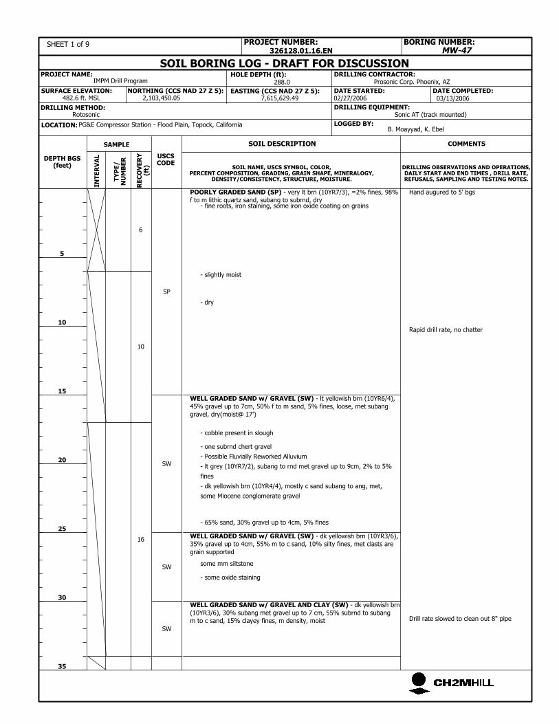
10
- 65% sand, 30% gravel up to 4cm, 5% fines
SW
6
SW
16
- fine roots, iron staining, some iron oxide coating on grains
- slightly moist
- dry
DATE COMPLETED:
- one subrnd chert gravel
DATE STARTED:
- lt grey (10YR7/2), subang to rnd met gravel up to 9cm, 2% to 5%
fines
- dk yellowish brn (10YR4/4), mostly c sand subang to ang, met,
some Miocene conglomerate gravel
USCSCODE
MW-47
5
10
15
20
25
30
35
DRILLING OBSERVATIONS AND OPERATIONS,DAILY START AND END TIMES , DRILL RATE,REFUSALS, SAMPLING AND TESTING NOTES.
SOIL NAME, USCS SYMBOL, COLOR,PERCENT COMPOSITION, GRADING, GRAIN SHAPE, MINERALOGY,
DENSITY/CONSISTENCY, STRUCTURE, MOISTURE.
PROJECT NUMBER:
COMMENTS
TY
PE
/N
UM
BE
R
SAMPLE
SW
- Possible Fluvially Reworked Alluvium
POORLY GRADED SAND (SP) - very lt brn (10YR7/3), =2% fines, 98%
f to m lithic quartz sand, subang to subrnd, dry
WELL GRADED SAND w/ GRAVEL (SW) - lt yellowish brn (10YR6/4),
45% gravel up to 7cm, 50% f to m sand, 5% fines, loose, met subang
gravel, dry(moist@ 17')
WELL GRADED SAND w/ GRAVEL (SW) - dk yellowish brn (10YR3/6),
35% gravel up to 4cm, 55% m to c sand, 10% silty fines, met clasts are
grain supported
WELL GRADED SAND w/ GRAVEL AND CLAY (SW) - dk yellowish brn
(10YR3/6), 30% subang met gravel up to 7 cm, 55% subrnd to subang
m to c sand, 15% clayey fines, m density, moist
Hand augured to 5' bgs
Rapid drill rate, no chatter
Drill rate slowed to clean out 8" pipe
SP
- cobble present in slough
Prosonic Corp. Phoenix, AZ
7,615,629.49 03/13/2006IN
TE
RV
AL
SOIL BORING LOG - DRAFT FOR DISCUSSION
02/27/2006
HOLE DEPTH (ft):
Sonic AT (track mounted)
RE
CO
VE
RY
(ft)
DEPTH BGS(feet)
BORING NUMBER:SHEET 1 of 9
288.0
DRILLING EQUIPMENT:
SURFACE ELEVATION:2,103,450.05
DRILLING METHOD:Rotosonic
IMPM Drill Program
LOGGED BY:
SOIL DESCRIPTION
PG&E Compressor Station - Flood Plain, Topock, California
326128.01.16.EN
B. Moayyad, K. Ebel
482.6 ft. MSLEASTING (CCS NAD 27 Z 5):NORTHING (CCS NAD 27 Z 5):
- some oxide staining
PROJECT NAME:
some mm siltstone
LOCATION:
DRILLING CONTRACTOR:

SW
SW
GW
SP
SW
SW
Moderate Drill Rate
Drill rate slows to 2' / min
Collected Isoflow sample
Soil sample collected
SW
482.6 ft. MSL
B. Moayyad, K. Ebel
NORTHING (CCS NAD 27 Z 5):
326128.01.16.EN
LOCATION:
Drilling smooth but preceeds less
rapidly
DRILLING CONTRACTOR:IMPM Drill Program
LOGGED BY:
SOIL DESCRIPTION
PROJECT NAME:
WELL GRADED SAND w/ GRAVEL (SW) - yellowish brn (10YR5/4),
40% subang met gravel up to 9cm, 55% f to c met sand, 5% silty fines,
clast supported, m density, wet
WELL GRADED GRAVEL w/ SILT AND SAND (GW) - brn (7.5YR5/4),
55% subang to ang met gravel up to 4cm, 25% f to c sand, 20% silty
fines, dense, moist to dry
POORLY GRADED SAND w/ GRAVEL (SP) - pale brn (10TR6/3), 30% f
subang gravel up to 2 cm, 65% mostly c sand, =2% fines
WELL GRADED SAND w/ GRAVEL (SW) - Pale brn (10YR6/3), 30%
subang met gravel up to 5cm, 60% subrnd to subang m to c met sand,
10% silty fines, wet
WELL GRADED SAND w/ GRAVEL (SW) - 40% subang met gravel up
to 6cm, 55% subrnd to ang sand, 5% fines
WELL GRADED SAND w/ GRAVEL (SW) - dr yellowish brn (10YR3/6),
30% gravel, 60% sand, 10% silty fines
WELL GRADED SAND w/ GRAVEL (SW) - yellowish brn (10YR5/4),
35% subang met gravel up to 4cm, 60% subrnd sand, 5% silty fines,
loose, moist to wet
2,103,450.05
DRILLING EQUIPMENT:
Prosonic Corp. Phoenix, AZ
SURFACE ELEVATION:
DRILLING METHOD:Rotosonic Sonic AT (track mounted)
02/27/2006
40
45
50
55
60
65
70
SAMPLE
TY
PE
/N
UM
BE
R
COMMENTS
PROJECT NUMBER:
DRILLING OBSERVATIONS AND OPERATIONS,DAILY START AND END TIMES , DRILL RATE,REFUSALS, SAMPLING AND TESTING NOTES.
MW-47
USCSCODE
DATE COMPLETED:DATE STARTED:7,615,629.49
SOIL NAME, USCS SYMBOL, COLOR,PERCENT COMPOSITION, GRADING, GRAIN SHAPE, MINERALOGY,
DENSITY/CONSISTENCY, STRUCTURE, MOISTURE.
10
- gravel is mostly fine
- more gravel below 38'
288.0
9.5
- moist sandy zone, 55% gravel, 35% sand, 10% fines
10
2.5
03/13/2006IN
TE
RV
AL
SOIL BORING LOG - DRAFT FOR DISCUSSION
SHEET 2 of 9
HOLE DEPTH (ft):
- soil dries out
- lt grey (10YR7/2) and powder dry
DEPTH BGS(feet)
BORING NUMBER:
PG&E Compressor Station - Flood Plain, Topock, California
- dry silty lt grey GW below 65'
EASTING (CCS NAD 27 Z 5):
RE
CO
VE
RY
(ft)
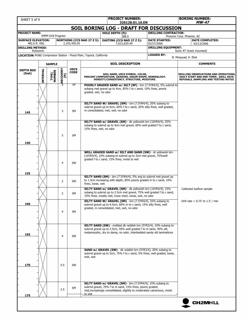
SM
5.5
4
4
2
2
4
5
3
6
SW
SAND w/ GRAVEL (SW) - dk reddish brn (5YR3/4), 20% subang to
subrnd gravel up to 5cm, 75% f to c sand, 5% fines, well graded, loose,
met, wet
SILTY SAND (SW) - mottled dk reddish brn (5YR3/4), 10% subang to
subrnd gravel up to 2.5cm, 50% well graded f to m sand, 40% silt,
metamorphic, dry to damp, no odor, interbedded sandy silt laminations
SILTY SAND W/ GRAVEL (SM) - brn (7.5YR4/4), 25% subang to
subrnd gravel up to 6.5cm, 60% m to c sand, 15% silty fines, well
graded, m consolidated, met, wet, no odor
SILTY SAND w/ GRAVEL (SM) - dk yellowish brn (10YR4/4), 15%
subang to subrnd up to 2.5cm met gravel, 75% well graded f to c sand,
10% fines, mostly met, trace chert, loose, wet, no odor
SILTY SAND (SM) - brn (7.5YR4/4), 5% ang to subrnd met gravel up
to 1.5cm increasing with depth, 85% poorly graded m to c sand, 10%
fines, loose, wet
WELL GRADED SAND w/ SILT AND SAND (SW) - dr yellowish brn
(10YR4/4), 10% subang to subrnd up to 3cm met gravel, 75%well
graded f to c sand, 15% fines, moist to wet
SILTY SAND w/ GRAVEL (SM) - dk yellowish brn (10YR4/4), 25%
subang to subrnd up to 4cm met gravel, 60% well graded f to c sand,
15% fines, wet, no odor
POORLY GRADED SAND w/ SILT (SP) - brn (7.5YR4/4), 5% subrnd to
subang met gravel up to 4cm, 85% f to c sand, 10% fines, poorly
graded, wet, no odor
SILTY SAND W/ GRAVEL (SM) - brn (7.5YR4/4), 20% subang to
subrnd gravel up to 6cm, 60% f to c sand, 20% silty fines, well graded,
m consolidated, met, wet, no odor
SW
SM
SM
SW
SW
SM
SM
SP
SILTY SAND w/ GRAVEL (SM) - brn (7.5YR4/4), 15% subang to
subrnd gravel, 70% f to m sand, 15% fines, poorly graded,
met,increasingly consolidated, slightly to moderately calcareous, moist
to wet
Collected Isoflow sample
Drill rate = 0.75' to 1.5' / min
Rotosonic Sonic AT (track mounted)
02/27/2006
288.0 Prosonic Corp. Phoenix, AZ
7,615,629.49 03/13/2006IN
TE
RV
AL
SOIL BORING LOG - DRAFT FOR DISCUSSIONHOLE DEPTH (ft):
SURFACE ELEVATION:
RE
CO
VE
RY
(ft)
DEPTH BGS(feet)
BORING NUMBER:
PG&E Compressor Station - Flood Plain, Topock, CaliforniaLOCATION:
SHEET 5 of 9
DATE STARTED:
SAMPLE
TY
PE
/N
UM
BE
R
COMMENTS
PROJECT NUMBER:
SOIL NAME, USCS SYMBOL, COLOR,PERCENT COMPOSITION, GRADING, GRAIN SHAPE, MINERALOGY,
DENSITY/CONSISTENCY, STRUCTURE, MOISTURE.
DRILLING OBSERVATIONS AND OPERATIONS,DAILY START AND END TIMES , DRILL RATE,REFUSALS, SAMPLING AND TESTING NOTES.
145
150
155
160
165
170
175
MW-47
DRILLING METHOD:
DATE COMPLETED:2,103,450.05
DRILLING EQUIPMENT:
PROJECT NAME:
USCSCODE
B. Moayyad, K. EbelLOGGED BY:
482.6 ft. MSL
IMPM Drill Program
EASTING (CCS NAD 27 Z 5):
2.5
NORTHING (CCS NAD 27 Z 5):
326128.01.16.EN
SOIL DESCRIPTION
DRILLING CONTRACTOR:
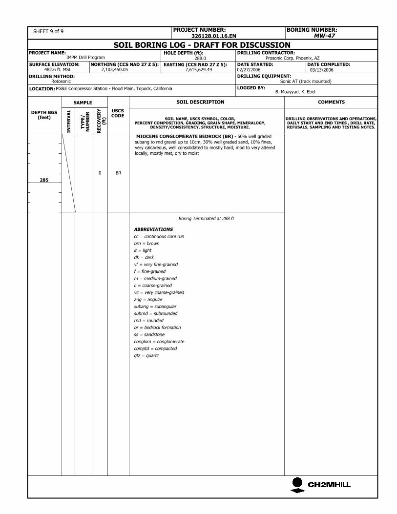
LOCATION:
DRILLING CONTRACTOR:
326128.01.16.EN
PROJECT NAME:
LOGGED BY:
SOIL DESCRIPTION
PG&E Compressor Station - Flood Plain, Topock, California
BORING NUMBER:
DEPTH BGS(feet)
MIOCENE CONGLOMERATE BEDROCK (BR) - 60% well graded
subang to rnd gravel up to 10cm, 30% well graded sand, 10% fines,
very calcareous, well consolidated to mostly hard, mod to very altered
locally, mostly met, dry to moist
EASTING (CCS NAD 27 Z 5):
ABBREVIATIONS
cc = continuous core run
brn = brown
lt = light
dk = dark
vf = very fine-grained
f = fine-grained
m = medium-grained
c = coarse-grained
vc = very coarse-grained
ang = angular
subang = subangular
subrnd = subrounded
rnd = rounded
br = bedrock formation
ss = sandstone
conglom = conglomerate
comptd = compacted
qtz = quartz
BR
Boring Terminated at 288 ft
IMPM Drill Program
NORTHING (CCS NAD 27 Z 5):
RE
CO
VE
RY
(ft)
482.6 ft. MSL
B. Moayyad, K. Ebel
0
285
DATE STARTED: DATE COMPLETED:
MW-47
DRILLING OBSERVATIONS AND OPERATIONS,DAILY START AND END TIMES , DRILL RATE,REFUSALS, SAMPLING AND TESTING NOTES.
SOIL NAME, USCS SYMBOL, COLOR,PERCENT COMPOSITION, GRADING, GRAIN SHAPE, MINERALOGY,
DENSITY/CONSISTENCY, STRUCTURE, MOISTURE.
PROJECT NUMBER:
COMMENTS
TY
PE
/N
UM
BE
R
SAMPLE
USCSCODE
02/27/2006
HOLE DEPTH (ft):
SHEET 9 of 9
SOIL BORING LOG - DRAFT FOR DISCUSSION
INT
ER
VA
L03/13/20067,615,629.49
288.0
Sonic AT (track mounted)RotosonicDRILLING METHOD:
2,103,450.05SURFACE ELEVATION:
DRILLING EQUIPMENT:
Prosonic Corp. Phoenix, AZ


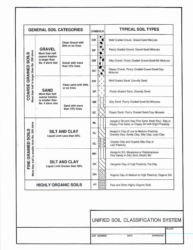
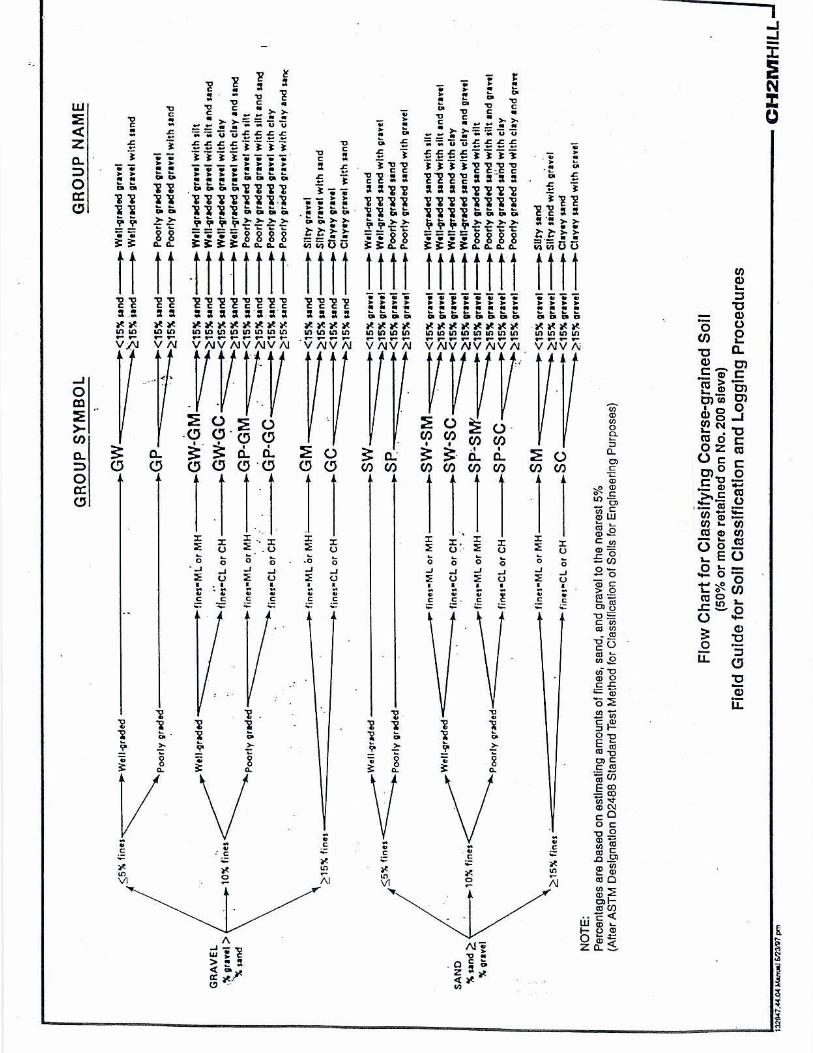
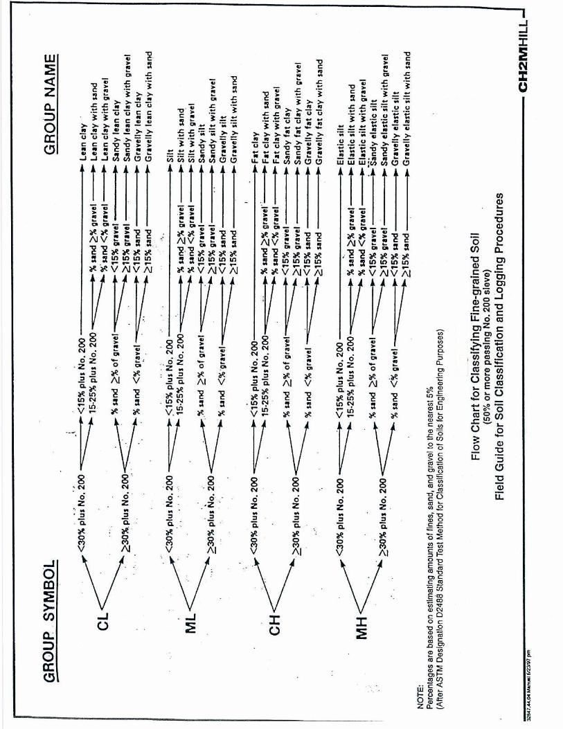


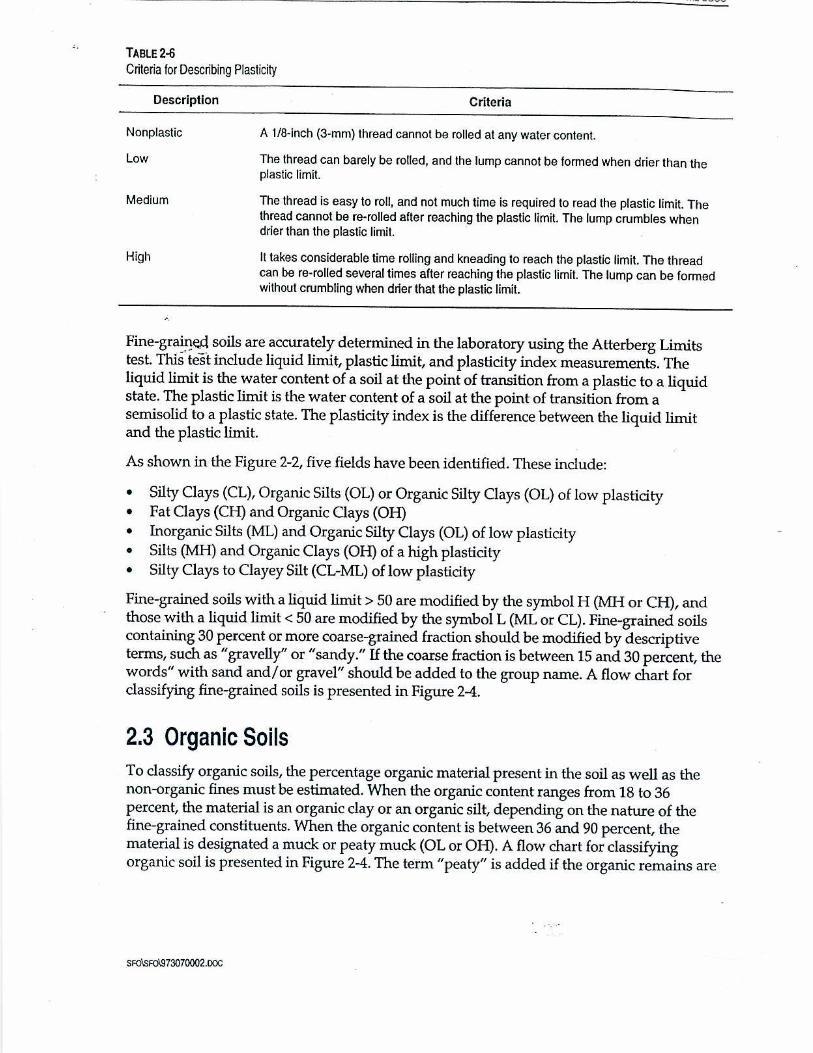
ES081312222904BAO 1 OF 2
SOP-B4
Boring Abandonment Standard Operating Procedures for PG&E Topock Program
The purpose of this standard operating procedure (SOP) is to describe methods to abandon drill borings to the surface. The guideline covers all drilling methods and includes borings through surface casings.
REQUIRED DOCUMENTS
1) Event-specific sampling and analysis plan, work plan or event-specific field instructions. Planned borehole depth, proposed well construction/specifications, and field sampling summary table, if available.
2) Applicable project work plan or monitoring plan. Refer to Topock Program Sampling, Analysis, and Field Procedures Manual and Quality Assurance Project Plan (Procedures Manual), as required.
3) San Bernardino County Department of Health well abandonment (destruction) permit.
4) Topock Program Health and Safety Plan (HSP).
5) Blank sampling log and field notebook.
PREPARATION AND SETUP
1) Review event-specific work plan or event-specific field instructions, previous sampling logs, Procedures Manual, and HSP.
2) Initiate field logbook for sampling activity.
3) Review sampling procedures and equipment, and planned sample depths with drilling contractor and field crew.
4) Inspect all required field equipment.
Equipment List
• Truck-mounted drilling rig, skid rig, or barge-mounted tripod rig
• Hollow-stem augers and associated equipment or either rotary-drilling or sonic- drilling equipment
• Steel or Schedule 40 PVC casing, of appropriate diameter for required installations (at least 6.25-inch inside diameter if surface casing is required)
• Approved water source
• Cement
• Bentonite
TOPOCK FIELD PROCEDURE MANUAL SOP-B4, REVISION 0, 3/31/05
2 OF 2 ES081312222904BAO
GUIDELINES
California Department of Water Resources, June 1991, Bulletin 74-90 (Supplement to Bulletin 74-81) California Well Standards.
PROCEDURES
Abandonment
1) The borehole will be grouted from total depth to the surface with bentonite-cement grout. The cement-bentonite grout will be installed continuously in one operation from the bottom of the space to be grouted to the ground surface.
2) The grout mixture will consist of 94 pounds of cement (1 bag) per 6 gallons of water and 2 to 3 pounds of powdered bentonite per bag of cement to reduce shrinkage.
3) The source of the water used in the grout mixture must be from a pre-approved source.
4) If there is any risk of borehole collapse upon removal of the drill casing, then the grout will be added prior to the removal of the drill casing. The grouting can be completed in stages, grouting 50 to 100 feet at a time, removing 50 to 100 feet of drill casing, and then repeating until the grout has reached the surface and the final casing removed.
5) When installing grout in soil borings, the grout will be installed through a tremie pipe that is placed inside the drill casing to the bottom of the borehole.
6) The production of grout will be completed to eliminate the preparation of excess/waste grout.
Waste Disposal
1) The soil cuttings are to be drummed and managed as described in SOP Disposal of Waste Fluids and Soils and the investigation-derived waste management plan.
2) Minimal quantities of grout may be included in the water or soil waste streams. The quantity of grout will be limited to that produced during cleaning of grouting equipment or decontamination of drill casing.
KEY CHECKS AND PREVENTATIVE MAINTENANCE
• Check that the drilling rig or soil-coring rig is in working order.
• Check that the borehole is grouted to the ground surface at the completion of drilling and sampling.
ES081312222904BAO 1 OF 4
SOP-B5
Decontamination of Personnel and Equipment, Well Drilling, and Subsurface Sampling and Investigations
Standard Operating Procedures for PG&E Topock Program
This standard operating procedure provides general guidelines for the decontamination of personnel, sampling equipment, and monitoring equipment used in potentially-contaminated areas.
REQUIRED DOCUMENTS
1) Event-specific sampling and analysis plan (SAP).
2) Applicable project work plan or monitoring plan, which includes a health and safety plan. Refer to Topock Program Sampling, Analysis, and Field Procedures Manual and Quality Assurance Project Plan, as required.
PREPARATION AND SETUP
1) Initiate field log sampling book for activity.
2) Inspect all equipment necessary to carry out activities detailed in event-specific SAP.
3) Review decontamination guidelines for equipment necessary to carry out activities.
Equipment List
• Demonstrated analyte-free, deionized water (specifically, ASTM Type II water)
• Distilled water
• Potable water; must be from a municipal water supplier, otherwise an analysis must be run for appropriate volatile and semivolatile organic compounds and inorganic chemicals (e.g., Target Compound List and Target Analyte List chemicals)
• 2.5% (W/W) Liquinox and water solution
• Large plastic pails or tubs for Liquinox and water, scrub brushes, spray or squirt bottles for Liquinox solution, and distilled or deionized water, plastic bags, and sheets
• Department of Transportation (DOT)-approved 55-gallon drum for disposal of waste
• Nitrile or latex gloves
• Decontamination pad and steam cleaner/high pressure cleaner for large equipment
TOPOCK FIELD PROCEDURE MANUAL SOP-B5, REVISION 0, 3/31/05
2 OF 4 ES081312222904BAO
GUIDELINES
Personnel Decontamination
Decontamination should be performed after completion of tasks whenever personnel come in contact with contaminated (or potentially-contaminated) soils or fluids. Full or emergency decontamination should be performed when contaminant concentrations are not known and when potentially-contaminated fluids come into contact with skin beneath clothing, eyes, nose, or ears.
Procedures for full/emergency decontamination are to:
1) Remove contaminated clothing.
2) Step into containment area (decontamination pad or large pail).
3) Rinse away fluids and soil.
4) Wash skin with Liquinox solution in such a way as to not abrade skin. (Liquinox solution should be made with potable water and sufficient detergent to create foamy suds.) Eyes and mucus membranes in contact with contaminants must be washed with eye wash or drinking water continuously for at least 15 minutes.
5) Rinse with potable water.
6) If no other clothes are available, wash affected clothes in Liquinox solution prior to donning. If other clothes are available, contaminated clothes may be isolated for later wash or disposed of along with personal protective equipment (PPE).
7) Any PPE worn (including disposable latex booties, gloves, and disposable coveralls) should be discarded into DOT-approved 55-gallon drum located at the MW-20 bench.
8) Dispose of wash and rinseate water in an appropriate container with other chromium contaminated fluids. These fluids may be taken to the MW-20 bench for treatment or to a Baker® tank within the PG&E facility for containerization.
9) Replace all appropriate clothing and PPE before resuming work or departing site.
Moist soil or water containing known concentrations of hexavalent chromium less than 50 parts per billion that comes into contact with hands need not require full decontamination. Dry soil containing chromium that comes into contact with clothing can also be decontaminated in an abbreviated manner.
Daily decontamination and minor exposure contact decontamination procedures are to:
1) Wash hands and skin that comes in contact with soils or water that may contain small concentrations of chromium as soon as possible after contact. Wash with Liquinox solution and rinse with potable water.
2) If contaminated soil or water contacts hands through hole or over lip of gloves, remove gloves and wash hands thoroughly before donning new gloves.
3) Discard gloves into DOT-approved 55-gallon drum located on the MW-20 bench at the end of the day or event.
TOPOCK FIELD PROCEDURE MANUAL SOP-B5, REVISION 0, 3/31/05
ES081312222904BAO 3 OF 4
4) Remove coveralls or dry soils from clothing before leaving site. Clothing contaminated by moist soil or water containing hexavalent chromium should be removed and promptly washed.
5) At the end of the work day, shower entire body, including hair, either at the work site or at hotel.
Sampling Equipment Decontamination—Groundwater Sampling Pumps
Sampling pumps are decontaminated after each use as follows:
1) Don waterproof (nitrile or latex) gloves.
2) Run pump and reusable tubing through with Liquinox solution (made with potable water) so that the pump and all portions or the tubing have been flushed with the solution for at least 30 to 60 seconds. More time is required if water is present in the tubing. If unsure, run for 2.5 minutes. Outside of the tubing should also be submerged and washed in the solution.
3) Run pump and reusable tubing through first rinse (with potable or distilled water) so that the pump and all portions or the tubing have been flushed with the solution for at least 60 seconds. More time is required if any suds are present in the pump or tubing.
4) Run pump and reusable tubing through second rinse (with distilled water) so that the pump and all portions or the tubing have been flushed with the solution for at least 30 seconds. More time is required if water from first rinse is present in tubing.
5) Equipment blank samples may be taken at this point using ASTM Type II water or distilled water as required by laboratory.
Sampling Equipment Decontamination—Other Equipment
Reusable sampling equipment is decontaminated after each use as follows:
1) Don nitrile or latex gloves.
2) Wash all equipment surfaces that contacted the potentially contaminated soil/water with Liquinox solution (made from potable water). Water quality meters that are not placed within wells should not be washed with detergent, as this will degrade sensors; these meters should be double-rinsed. Any portion of equipment that is placed inside wells (including cables and pipe) and that comes in contact with moisture should be washed with detergent.
3) Rinse equipment and supplies with potable water, if the equipment is not used to collect groundwater or soil samples. Equipment used to collect samples or take water quality parameters should be rinsed with distilled water.
4) Air dry or towel dry with paper towels.
5) Collect all rinseate and dispose of in Baker® tank within the PG&E facility or Denbeste® tank at the MW-20 bench.
TOPOCK FIELD PROCEDURE MANUAL SOP-B5, REVISION 0, 3/31/05
4 OF 4 ES081312222904BAO
6) Decontamination materials (e.g., plastic sheeting, tubing, etc.) that have come in contact with used decontamination fluids or sampling equipment will be disposed of in DOT-approved 55-gallon drums if highly contaminated. If not contaminated, equipment can be washed and disposed of in trash.
7) Preserved bottles may need to be washed before being packed or handed without gloves. The outsides of filled bottles should be rinsed and toweled dry to prevent contact with strong acids or based.
Heavy Equipment and Tools
Heavy equipment such as drilling rigs, drilling rods/tools, and the backhoe will be decontaminated upon arrival at the site and between locations as follows:
1) Set up a decontamination pad in designated area.
2) Steam clean heavy equipment until no visible signs of dirt are observed. This may require wire or stiff brushes to dislodge dirt from some areas.
KEY CHECKS AND ITEMS
• Clean with solutions of Liquinox and potable water. Rinse with distilled or deionized water if equipment is used to collect samples or water readings; otherwise, rinse with potable water.
• Equipment placed within wells should be thoroughly decontaminated and before being placed in a well. All potions of this equipment that come into contact with moisture should be decontaminated.
• Decontaminate filled sample bottles before relinquishing them to anyone.
ES081312222904BAO 1 OF 2
SOP-B7
Homogenization of Soil and Sediment Samples Standard Operating Procedures for PG&E Topock Program
The homogenization of soil and sediment samples is performed to minimize any bias of sample representativeness introduced by the natural stratification of constituents within the sample. Standard techniques for soil and sediment homogenization and equipment are provided in this SOP. These procedures do not apply to aliquots collected for volatile organic compounds (VOCs) or field gas chromography screening; samples for these analyses should NOT be homogenized.
REQUIRED DOCUMENTS
1) Event-specific sampling and analysis plan (SAP).
2) Applicable project work plan or monitoring plan. Refer to Topock Program Sampling, Analysis, and Field Procedures Manual and Quality Assurance Project Plan, as required.
3) Topock Program Health and Safety Plan (HSP).
4) Previous sampling logs.
5) Blank sampling logs and field notebook.
PREPARATION AND SETUP
1) Review event-specific SAP or event-specific field instructions, previous sampling logs, Procedures Manual, and HSP.
2) Initiate field logbook for sampling activity.
EQUIPMENT LIST
• Sample containers • Stainless-steel spoons or spatulas • Stainless-steel pans • Phthalate-free gloves
PROCEDURES
Sample Homogenization
1) Soil and sediment samples to be analyzed for semivolatiles, pesticides, polychlorinated biphenyls, metals, cyanide, or field x-ray fluorescence screening should be homogenized in the field.
2) After a sample is taken, a stainless-steel spatula should be used to remove the sample from the split spoon or other sampling device. The sampler should not use fingers to do this, as gloves may introduce organic interferences into the sample.
TOPOCK FIELD PROCEDURE MANUAL SOP-B7, REVISION 0, 3/31/05
2 OF 2 ES081312222904BAO
3) Samples for VOCs should be taken immediately upon opening the spoon and should not be homogenized.
4) Prior to homogenizing the soil or sediment sample, any rocks, twigs, leaves, or other debris should be removed from the sample.
5) The sample should be placed in a decontaminated stainless-steel pan and thoroughly mixed using a stainless-steel spoon. The soil or sediment material in the pan should be scraped from the sides, corners, and bottom, rolled into the middle of the pan, and initially mixed.
6) The sample should then be quartered and moved to the four corners of the pan. Each quarter of the sample should be mixed individually, then rolled to the center of the pan and mixed with the entire sample again.
Equipment Decontamination
1) All stainless-steel spoons, spatulas, and pans must be decontaminated following procedures specified in SOP Decontamination of Personnel and Equipment prior to homogenizing the sample.
2) A composite equipment rinse blank of homogenization equipment should be taken each day it is used.
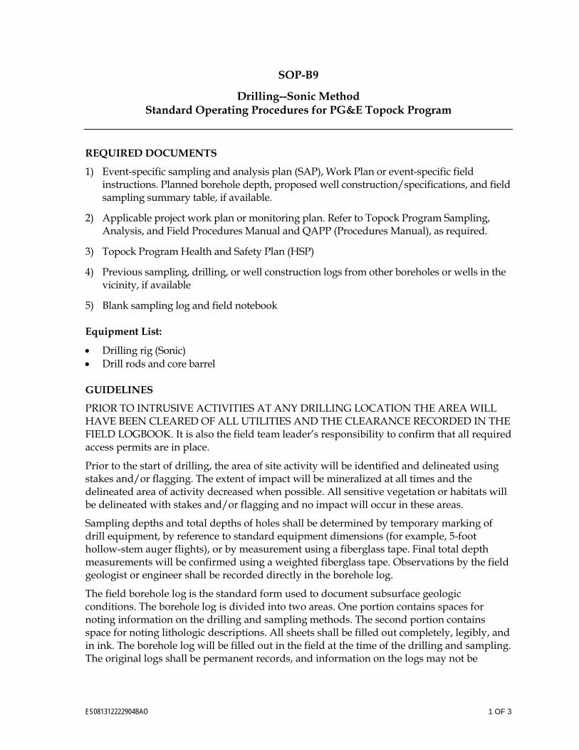
ES081312222904BAO 1 OF 3
SOP-B9
Drilling--Sonic Method Standard Operating Procedures for PG&E Topock Program
REQUIRED DOCUMENTS
1) Event-specific sampling and analysis plan (SAP), Work Plan or event-specific field instructions. Planned borehole depth, proposed well construction/specifications, and field sampling summary table, if available.
2) Applicable project work plan or monitoring plan. Refer to Topock Program Sampling, Analysis, and Field Procedures Manual and QAPP (Procedures Manual), as required.
3) Topock Program Health and Safety Plan (HSP)
4) Previous sampling, drilling, or well construction logs from other boreholes or wells in the vicinity, if available
5) Blank sampling log and field notebook
Equipment List:
• Drilling rig (Sonic) • Drill rods and core barrel
GUIDELINES
PRIOR TO INTRUSIVE ACTIVITIES AT ANY DRILLING LOCATION THE AREA WILL HAVE BEEN CLEARED OF ALL UTILITIES AND THE CLEARANCE RECORDED IN THE FIELD LOGBOOK. It is also the field team leader’s responsibility to confirm that all required access permits are in place.
Prior to the start of drilling, the area of site activity will be identified and delineated using stakes and/or flagging. The extent of impact will be mineralized at all times and the delineated area of activity decreased when possible. All sensitive vegetation or habitats will be delineated with stakes and/or flagging and no impact will occur in these areas.
Sampling depths and total depths of holes shall be determined by temporary marking of drill equipment, by reference to standard equipment dimensions (for example, 5-foot hollow-stem auger flights), or by measurement using a fiberglass tape. Final total depth measurements will be confirmed using a weighted fiberglass tape. Observations by the field geologist or engineer shall be recorded directly in the borehole log.
The field borehole log is the standard form used to document subsurface geologic conditions. The borehole log is divided into two areas. One portion contains spaces for noting information on the drilling and sampling methods. The second portion contains space for noting lithologic descriptions. All sheets shall be filled out completely, legibly, and in ink. The borehole log will be filled out in the field at the time of the drilling and sampling. The original logs shall be permanent records, and information on the logs may not be
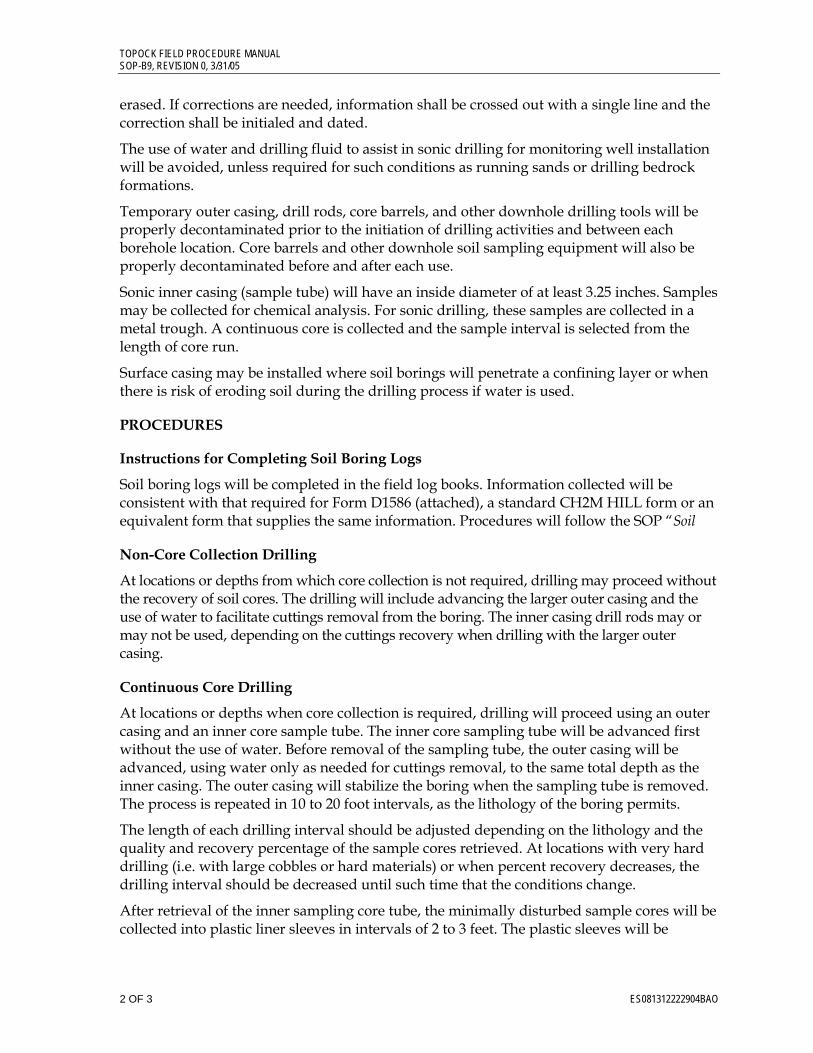
TOPOCK FIELD PROCEDURE MANUAL SOP-B9, REVISION 0, 3/31/05
2 OF 3 ES081312222904BAO
erased. If corrections are needed, information shall be crossed out with a single line and the correction shall be initialed and dated.
The use of water and drilling fluid to assist in sonic drilling for monitoring well installation will be avoided, unless required for such conditions as running sands or drilling bedrock formations.
Temporary outer casing, drill rods, core barrels, and other downhole drilling tools will be properly decontaminated prior to the initiation of drilling activities and between each borehole location. Core barrels and other downhole soil sampling equipment will also be properly decontaminated before and after each use.
Sonic inner casing (sample tube) will have an inside diameter of at least 3.25 inches. Samples may be collected for chemical analysis. For sonic drilling, these samples are collected in a metal trough. A continuous core is collected and the sample interval is selected from the length of core run.
Surface casing may be installed where soil borings will penetrate a confining layer or when there is risk of eroding soil during the drilling process if water is used.
PROCEDURES
Instructions for Completing Soil Boring Logs
Soil boring logs will be completed in the field log books. Information collected will be consistent with that required for Form D1586 (attached), a standard CH2M HILL form or an equivalent form that supplies the same information. Procedures will follow the SOP “Soil
Non-Core Collection Drilling
At locations or depths from which core collection is not required, drilling may proceed without the recovery of soil cores. The drilling will include advancing the larger outer casing and the use of water to facilitate cuttings removal from the boring. The inner casing drill rods may or may not be used, depending on the cuttings recovery when drilling with the larger outer casing.
Continuous Core Drilling
At locations or depths when core collection is required, drilling will proceed using an outer casing and an inner core sample tube. The inner core sampling tube will be advanced first without the use of water. Before removal of the sampling tube, the outer casing will be advanced, using water only as needed for cuttings removal, to the same total depth as the inner casing. The outer casing will stabilize the boring when the sampling tube is removed. The process is repeated in 10 to 20 foot intervals, as the lithology of the boring permits.
The length of each drilling interval should be adjusted depending on the lithology and the quality and recovery percentage of the sample cores retrieved. At locations with very hard drilling (i.e. with large cobbles or hard materials) or when percent recovery decreases, the drilling interval should be decreased until such time that the conditions change.
After retrieval of the inner sampling core tube, the minimally disturbed sample cores will be collected into plastic liner sleeves in intervals of 2 to 3 feet. The plastic sleeves will be
TOPOCK FIELD PROCEDURE MANUAL SOP-B9, REVISION 0, 3/31/05
ES081312222904BAO 3 OF 3
immediately sealed on both ends. The cores will be used for visual descriptions and may be used for analysis for geochemical and geotechnical parameters.
KEY CHECKS AND ITEMS
• Check entries to the soil boring log and field logbook in the field during sampling activities because the cores will be disposed at the end of the fieldwork, confirmation and corrections cannot be made later.
• Check that the sample numbers and intervals are properly specified.
• Ensure that drilling equipment is decontaminated prior to the beginning of work and between each borehole.
• All materials generated during sampling (debris, PPE, decontamination liquids, etc.) will be placed in approved IDW storage containers pending analysis and disposal off site as outlined in SOP-B6, Disposal of Waste Fluids and Solids (IDW).
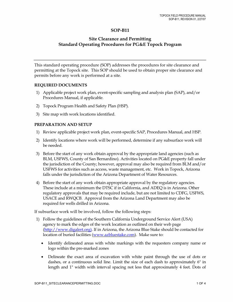
TOPOCK FIELD PROCEDURE MANUAL
SOP-B11, REVISION 01, 2/27/07
SOP-B11
Site Clearance and Permitting Standard Operating Procedures for PG&E Topock Program
This standard operating procedure (SOP) addresses the procedures for site clearance and permitting at the Topock site. This SOP should be used to obtain proper site clearance and permits before any work is performed at a site.
REQUIRED DOCUMENTS
1) Applicable project work plan, event-specific sampling and analysis plan (SAP), and/or Procedures Manual, if applicable.
2) Topock Program Health and Safety Plan (HSP).
3) Site map with work locations identified.
PREPARATION AND SETUP
1) Review applicable project work plan, event-specific SAP, Procedures Manual, and HSP.
2) Identify locations where work will be performed, determine if any subsurface work will be needed.
3) Before the start of any work obtain approval by the appropriate land agencies (such as BLM, USFWS, County of San Bernardino). Activities located on PG&E property fall under the jurisdiction of the County; however, approval may also be required from BLM and/or USFWS for activities such as access, waste management, etc. Work in Topock, Arizona falls under the jurisdiction of the Arizona Department of Water Resources.
4) Before the start of any work obtain appropriate approval by the regulatory agencies. These include at a minimum the DTSC if in California, and ADEQ is in Arizona. Other regulatory approvals that may be required include, but are not limited to CDFG, USFWS, USACE and RWQCB. Approval from the Arizona Land Department may also be required for wells drilled in Arizona.
If subsurface work will be involved, follow the following steps:
1) Follow the guidelines of the Southern California Underground Service Alert (USA) agency to mark the edges of the work location as outlined on their web page (http://www.digalert.org). If in Arizona, the Arizona Blue Stake should be contacted for location of buried facilities (www.azbluestake.com). Make sure to:
Identify delineated areas with white markings with the requesters company name or logo within the pre-marked zones
Delineate the exact area of excavation with white paint through the use of dots or dashes, or a continuous solid line. Limit the size of each dash to approximately 6" in length and 1" width with interval spacing not less that approximately 4 feet. Dots of
SOP-B11_SITECLEARANCEPERMITTING.DOC 1 OF 4
TOPOCK FIELD PROCEDURE MANUAL
SOP-B11, REVISION 01, 2/27/07
approximately 1" diameter are typically used to define arcs or radii and may be placed at closer intervals in lieu of dashes. Limit width of lines to 1".
For point locations (such as a soil boring or well) mark the exact location in the USA or Blue Stake box with a stake. Make sure the delineated area around the stake is of adequate radius (50 to 100 feet is appropriate for drilling).
2) Call USA at 1-800-227-2600 or Arizona Blue Stake at 1-800-782-5348 at least three working days before the start of work at the identified location and provide them with the information requested on the location request form. Be ready to give the location in terms of feet relative to I-40 and to Park Moabi Road when calling. You will be assigned a Dig Alert Number, file this number until work at the delineated area is complete. (The number does expire after two weeks and a new number may need to be obtained if work has been delayed.)
3) Mark the Dig Alert Number in the delineated area using white paint as soon as possible after calling USA or Arizona Blue Stake.
4) If the location is in a developed area, contact a private utility locator and have them perform a sweep of the delineated work area. Util-Locate at (866) 421-5325 is typically used for this service.
5) In some cases the utility companies may need to be contacted directly by CH2M HILL. If the following companies do not respond to the USA or Blue Stake ticket or if we are working in their easements, use the following contact information and procedures:
Southwest Gas: Main contact is Jim Default/702-365-2097(The required minimum clearance distance from gas pipelines is 18-inches.
Potholing may need to be performed in advance of design completionSouthwest Gas should be called prior to construction activities). If Southwest Gas does not come to the site after the USA call, contact them at their Bullhead City office at (928) 763-7766
Southern California Gas Co.: Main contact is Frank Castro/818-701-4566; secondary contact is Martin Woodsworth/818-701-4543. If we need to work in their easement, we must provide a letter from BLM giving us permission to be on the property. Southern California Gas Co. also requires advance notification of construction activities. They may also require a copy of the design drawing, potholing activities, and the issuance of a "Non-Interference" letter, if applicable, before work can proceed. One of their representatives may need to be in the field when digging is occurring near their pipeline.
TransWestern Pipeline Co.: Main contacts are Ron Westbrook (ROW Department)/713-345-3067 and Mike Baxter (Operations)/928-757-3620. They may require potholing if proposed construction activities are near their pipelines. Crossing pipeline requires filling out a simple form.
Burlington Northern Santa Fe Railroad: Main contact is Greg Rousseau (BNSF)/909-386-4079. Prior to work in their easements submit the proper application with the $250 fee to the Staubach Company.
SOP-B11_SITECLEARANCEPERMITTING.DOC 2 OF 4
TOPOCK FIELD PROCEDURE MANUAL
SOP-B11, REVISION 01, 2/27/07
City of Needles Utility Dept: Main contact is Ron Myers/760-326-5700 (ext. 7 for the utilities department). Work activities may need to be a minimum of 10 to 15 feet from their utility poles.
6) Do not start subsurface work at the site until the delineated area has been marked or cleared by the appropriate utility agencies.
If the work includes a performing a well installation or abandonment, or drilling a boring in California:
1) Apply for a San Bernardino County well permit two to three weeks before the start of drilling (one permit per well; cost is /$212.00 per well). Obtain a permit application by calling the Environmental Health Services Department at 1-909-387-4666 (open Monday through Friday, 8:00 a.m. to 5:00 p.m. The fee schedule for permits is located at http://www.sbcounty.gov/ dehs/FEESCHEDULE/feeschedule.htm#wateranchor. Fill out the appropriate permit form and provide it to the California-licensed driller contracted to perform the well installation. The driller is expected to review and file the permit with the San Bernardino County Department of Environmental Health Services (Steve Sesler), address below.
Environmental Health Services 385 N. Arrowhead, 2nd Floor San Bernardino, CA 92415-0160
2) A well permit needs to be obtained from San Bernardino County for well abandonmentby the same procedure described in #11. Check the 'destruction' box on the same permit form used for well installation.
3) A permit also needs to be obtained from San Bernardino County for any boring that reaches to or below the water table, even if a well is not actually installed. The permit process is the same as described in #11.
If the work includes a performing a well installation or abandonment, or drilling a boring in Arizona:
1) Apply for an Arizona Department of Water Resources (DWR) well permit two to three weeks before the start of drilling (one permit per well; cost is /$150.00 per well). Obtain a permit application by calling the DWR at 1-(602) 771-8500 (open Monday through Friday, 8:00 a.m. to 5:00 p.m. MST). All ADW permits and instructions can be found at http://www.azwater.gov/dwr/Content/Find_by_Category/Permits_Forms_Applications/default.htm Fill out the appropriate permit form (55-44A) and provide it to the Arizona-licensed driller contracted to perform the well installation. The driller is expected to review and file the permit with the Arizona Department of Water Resources address below.
Arizona Department of Water Resources 3550 N. Central Avenue Phoenix, AZ 85012
Upon completion of the well, the driller must submit a Driller Report and Well Log (Form 55-55) to the DWR within 30 days. The form and instructions can be found on the DWR webpage.
SOP-B11_SITECLEARANCEPERMITTING.DOC 3 OF 4
TOPOCK FIELD PROCEDURE MANUAL
SOP-B11, REVISION 01, 2/27/07
2) A well abandonment permit needs to be obtained from the Arizona Department of Water Resources prior to well abandonment (form 55-38). Exploratory wells that are abandoned before the drill rig leaves the site are exempt from the well abandonment permit requirements. The well abandonment form and instructions are included as Attachment 4 and can be found at the ADW webpage . No fee is required for filing this form.
Within 30 days of well abandonment a Well Abandonment Completion Report ( Form 55-58) must be filed with the DWR.
SOP-B11_SITECLEARANCEPERMITTING.DOC 4 OF 4
ES081312222904BAO 1 OF 4
SOP-B15
Volatile Organic Compound (VOC) Soil Sampling Standard Operating Procedures for PG&E Topock Program
This standard operating procedure (SOP) provides guidance for Volatile Organic Compound (VOC) sample collection from soil. Additional guidance for sample collection, preservation and handling is provided in Section 4.0 of the PG&E Quality Assurance Project Plan (QAPP). SOP-B2 and SOP-B3 Sampling, Analysis, and Field Procedures Manual, PG&E Topock Program (CH2M HILL, 2005) provides additional guidance for soil characterization and logging.
Required Documents 1) Event-specific planned sample table (PST).
2) Applicable project work plan or monitoring plan. Refer to the Procedures Manual and QAPP as required.
3) Topock Program Health and Safety Plan (HSP).
4) Previous sampling, drilling, or well construction logs from other boreholes or wells in the vicinity, if available.
5) Field notebook.
6) Database generated sampling logs.
Preparation and Setup 1) Review event-specific PST or event-specific field instructions, previous sampling logs,
Procedures Manual, and HSP.
2) Coordinate with the Project Chemist for coolers, sample containers, and courier pickup of the samples.
3) Initiate field logbook for sampling activity.
4) Review sampling procedures and planned sample depths with field crew.
5) Field-check and set up equipment for sampling, decontamination, spill prevention, and health and safety.
Equipment List
• Pre-labeled soil sample containers appropriate for sample analysis and preservation as called for in PST and QAPP (Pre-weighed Vials, glass jars, auger sleeves, etc.)
• Soil sampling equipment (stainless steel trowel, spatula, EnCore™ Sampler, EasyDraw Syringe®, or a disposable plastic syringe with a barrel smaller than the neck of the soil vial with the cap removed from the plunger, etc.)
• Field notebook
TOPOCK FIELD PROCEDURE MANUAL SOP-B15, REVISION 1,10/18/2006
2 OF 4 ES081312222904BAO
• Sediment sampling logs generated from database
• Blue or black waterproof or permanent ink pens
• Trash bags
• Paper towels
• Decontamination equipment (Alconox solution in spray bottle, brushes, buckets, rinse water spray bottle)
• Water level indicator
• Distilled water
• Coolers with ice
• Protective waterproof gloves (nitrile or latex)
SOIL SAMPLING LOGS DOCUMENTATION
Soil sampling logs or boring logs (SOP-B2 and SOP-B3 Sampling, Analysis, and Field Procedures Manual, PG&E Topock Program [CH2M HILL, 2005]) will be completed at the time of sample collection. Items to be documented on the sampling log include:
6) Sample Interval: The top and bottom depth of each sample run should be recorded on the log. Sampling includes samples collected for analysis as well as retrieved for logging purposes.
7) Sample Type and Number: Enter the sample type and number consistent with the sampling and analysis plan at the correct depth intervals. An “x” should be placed across the vertical interval where the environmental soil, grab groundwater, or geotechnical sample was collected.
8) Sample Recovery: Enter the length of retrieved sample to the nearest inch of sample recovered. Record total length and percent of sample recovered.
9) Sampling: Sampling difficulties shall be noted. The top of the sample shall be marked on the container.
10) Water Levels: Water-level measurements, where groundwater is encountered, are required for each boring. Changes in soil moisture shall be noted and, if there is no water encountered, a note to that effect shall be included on the sediment sampling log. The date and time of water-level measurements shall be documented.
At a minimum, sample identifiers (IDs) should be noted on sampling logs at the depth collected. When time and space allows, a summary of analytical sample information can be included.
VOLATILE ORGANIC COMPOUNDS (VOC) SOIL SAMPLING - COLLECTION OF SAMPLES FOR ANALYSIS
It is recommended (EPA Method 5035A) that VOC soil samples be collected in a coring device to minimize volatilization and soil disturbance to prevent constituent losses. After
TOPOCK FIELD PROCEDURE MANUAL SOP-B15, REVISION 1,10/18/2006
ES081312222904BAO 3 OF 4
collection, the sample shall be immediately transferred to the sample vial (to be used for analysis) and stored for no longer than 48 hours at 4 C ± 2º C prior to analysis. Freezing the samples between -7 and -20º C within 48 hours and maintaining them frozen until analysis allows a 14 day holding time. Chemical preservation techniques are also available as options.
Use either a commercially available sampler (such as the EnCore™ Sampler or EasyDraw Syringe®) or a disposable plastic syringe to collect VOC soil samples. To use a syringe, cut the syringe end of the barrel off and removed the rubber ‘cap’ from the plunger, prior to sampling (barrel of the syringe needs to be smaller than the neck of the soil vial). One sampler is needed for each sample aliquot to be collected (typically the laboratory will supply the sampler along with the sample vials, but arrangements must be made prior to sampling).
11) Weigh 3 empty samplers and note the weight. Using the same 3 samplers collect several trial samples (try to collect 5.0 ± 0.2g). Weigh each trial sample (total weight – syringe weight = sample weight) and note the length of the soil column in the syringe. Use the data to determine the length of soil in the syringe that corresponds to 5.0 grams. The length of the soil column equal to 5 grams becomes the volume for the project location. Discard each trial sample.
12) The VOC sample collection process should be completed in the least amount of time as possible in order to minimize the loss of VOCs. Sample collection should be done with the least amount of disturbance/disruption as possible. Additional, exposure of the sampling location’s surface layers should be considered if the material may have already lost VOCs or if it may have been contaminated by other means. Removal of surface layers can be accomplished by scraping the surface using a clean spatula, scoop, knife, or shovel.
13) Insert a clean coring tool into a freshly exposed surface; do not trap air between the sample and the plunger. For greater ease in pushing into the solid matrix, the front edge of these tools can be sharpened. The optimum diameter of the coring tool depends on the size of the opening of the collection vial (tool should fit inside mouth), the sample characteristics (e.g., particles size, cohesion), and volume of sample required for analysis. After an undisturbed sample has been obtained by pushing the barrel of the coring tool into a freshly exposed surface, quickly wipe the exterior of the barrel with a clean disposable towel. Transfer the sample into a pre-weighted vial by gently pushing the plunger, (use extreme care to ensure none of the preservative is lost if the sample is collected into a pre-preserved vial – water, methanol or NaHSO4), verify the sealing surfaces are clean, and secure the cap (the transfer should take less than 10 seconds). Note: Samples are collected in pre-weighed and pre-labeled vials provided by the laboratory; no additional labels are to be added to the vials! Complete the label attached by the laboratory (fill in sample ID-only). All vials from one sample location will be placed into a zip-lock bag and the sample information shall be recorded on a label attached to the bag.
14) As a last resort non-cohesive granular samples (sand, gravel, or a mixture of gravel and fines) that can not be easily obtained or transferred using coring tools, can be quickly sampled using a decontaminated stainless steel spatula or scoop. Decontamination is
TOPOCK FIELD PROCEDURE MANUAL SOP-B15, REVISION 1,10/18/2006
4 OF 4 ES081312222904BAO
covered in section 3.3 of the PG&E Program QAPP and in SOP-B5 Sampling, Analysis, and Field Procedures Manual, PG&E Topock Program (CH2M HILL, 2005).
15) As with the collection of aqueous samples for volatiles, collect at least 3 replicate samples. This will allow the laboratory an additional sample for reanalysis, if needed. The replicate samples should be taken from the same soil stratum or the same section of the solid waste being sampled, and within close proximity to the location from which the original sample was collected.
16) In addition, if a VOC sample is the only sample to be collected at a given location, collect at least one additional aliquot for the determination of percent moisture. Trip blanks and equipment blanks should be collected per the PG&E Program QAPP. However, trip blanks do not apply to samples that have been frozen upon collection.
17) Transport the sample at 4º C, to the lab in less than 48 hours or freeze (reagent water preserved samples to between -7 and -20º C) within 48 hours and transport frozen.
18) Complete Soil Sampling Logs and Chain of Custody Logs.
ES081312222904BAO 1 OF 7
SOP-B16
Field-portable X-Ray Fluorescence Soil Sampling Standard Operating Procedures for PG&E Topock Program
This Standard Operating Procedure (SOP) describes the analysis of in situ and ex situ soil and debris samples using a field portable x-ray fluorescence (XRF) instrument. SOP-B2 and SOP-B3 in the Sampling, Analysis, and Field Procedures Manual, PG&E Topock Program (SAFPM) (CH2M HILL, 2005) provides additional guidance for soil characterization and logging.
Required Documents 1. Event-specific planned sample table (PST).
2. Applicable project work plan or monitoring plan. Refer to the SAFPM and the PG&E Program Quality Assurance Project Plan, Revision 2, Topock Compressor Station, Needles, California (CH2M HILL, 2012) as required.
1. Topock Program Health and Safety Plan.
3. Field notebook.
4. Database generated chain-of-custody.
5. XRF Functional Check Log
Preparation and Setup 1. Review event-specific PST or event-specific field instructions, previous sampling logs,
SAFPM, and health and safety plan.
2. Coordinate with the project chemist for coolers, sample containers, and courier pickup of the samples.
3. Initiate field logbook for sampling activity.
4. Initiate electronic file for XRF instrument download.
5. Review sampling procedures and planned sample depths with field crew.
6. Field-check and set up equipment for functional checks, sampling, decontamination, spill prevention, and health and safety.
Equipment List
• Niton XRF meter and stand
• Spare battery chargers
• Field notebook
• Trowel for smoothing soil surfaces
SOP-B16, VERSION 2, 08/15/12
2 OF 7 ES081312222904BAO
• Reusable plastic bags or stainless steel tray
• Disposable sample cups with x-ray film and lids
• X-ray window film (Mylar, Kapton, Spectrolene, polypropylene, or equivalent; 2.5 to 6.0 micrometers thick)
• Disposable scoops, stainless-steel spoons, or other appropriate mixing tools
• Appropriate quality assurance/quality control (QA/QC) standards and blank sand
• Chemwipes
• Decontamination equipment (Alconox solution [or equivalent] in spray bottle, brushes, buckets, rinse water spray bottle) for mixing tools and trowels
• Protective waterproof gloves (nitrile or latex)
XRF Analysis Documentation The XRF sample results will be recorded by the associated software in an Excel format. The files will be downloaded at the end of each day and emailed to the project chemist for review. Any additional sample logging and sample collection should follow the protocol and procedures found in the appropriate SOP. Detailed notes should be recorded in the sampler’s field notebook or in a log generated from the field database. Items to be documented on the sampling log include (include as much of the following information in the XRF software as possible):
1. Record type of boring or excavation equipment and the total boring or excavation depth.
2. If multiple samples are being collected at one location at a variety of depths, record all sample depths.
3. Record date and time of sample collection in addition to the full sample ID that is listed in the PST.
4. Sampling difficulties shall be noted (that is, difficult slope or abnormal debris in sample location).
5. Analysis start time and the source count time (that is, 60, 90, or 120 seconds, etc.) will be documented on sample collection sheet. Analysis and count time are automatically recorded in the XRF software.
Field-portable XRF Soil Sampling, Collection of Samples for Analysis
In Situ Sample Preparation When the soil moisture is less than 20 percent, the error associated with moisture may be minimal. If areas are encountered where the moisture content is greater than 20 percent (moisture is visible), consult with the project chemist for options available for proceeding with field analysis.
For in situ analysis of soil:
SOP-B16, VERSION 2, 08/15/12
ES081312222904BAO 3 OF 7
1. Remove large or nonrepresentative debris from the selected location. This debris includes rocks, gravel, vegetation, and concrete.
2. Homogenize the location chosen for analysis by mixing in place an area approximately 4 inches by 4 inches by 3 inches deep using a clean (or decontaminated) stainless-steel or disposable spoon. Smooth and firmly tamp the location to provide as flat and smooth an area as possible.
3. Stretch a section of x-ray window film over the area to be tested to maintain a dust-free environment for the nose of the instrument. (Use in situ analysis for metals-only samples.)
4. To initiate a reading, position the nose of the XRF against the x-ray film, squeeze the shutter release, and firmly press the instrument flat against the surface. Source count times for in situ analysis usually range from 3 to 5 minutes, varying among instruments and depending on requirement detection limits.
5. After the in situ field screening is performed, inspect the nose of the instrument for contamination, which may affect future analysis. If necessary, clean it with a soft cloth or tissue.
For confirmation samples, or where samples for organic analysis are to be collected, the soil samples should be treated as ex situ samples, below.
For in situ analysis of debris:
1. In some cases, the large or nonrepresentative debris removed in Step 1 above may need analysis. The debris for analysis can include rocks, wood, concrete, etc.
2. Analyze debris that is too large or difficult to homogenize by locating multiple locations on the surface of the debris that are as flat and smooth as possible. Scan a minimum of three locations or approximately 10 percent of the surface area (whichever is greater).
3. Stretch a section of x-ray window film over the area to be tested to maintain a dust-free environment for the nose of the instrument. (Use in situ analysis for metals only samples.)
4. To initiate a reading, position the nose of the XRF against the x-ray film, squeeze the shutter release, and firmly press the instrument flat against the surface. Source count times for in situ analysis usually range from 3 to 5 minutes, varying among instruments and depending on requirement detection limits.
After the in situ field screening is performed, inspect the nose of the instrument for contamination, which may affect future analysis. If necessary, clean it with a soft cloth or tissue.
Ex Situ Sample Preparation For ex situ analysis:
There are several possible correct methods for the ex situ analysis of samples. The area that previously would have been homogenized for the in situ analysis should be scooped out and placed into a clean (or decontaminated) stainless-steel or disposable pan (do not use
SOP-B16, VERSION 2, 08/15/12
4 OF 7 ES081312222904BAO
plastic if organic analysis will be performed on any of this homogenized sample) using a stainless-steel or disposable spoon or spatula (do not use plastic if organic analysis are associated with the homogenized sample). The sample should then be thoroughly mixed (homogenized) using the same spoon or spatula.
1. The preferred method is to setup the portable field stand in an area where the XRF can be stationed and left in place for the day. Use the Niton software and a laptop computer to setup the method criteria and control the XRF instrument during the soil analysis.
a. Starting with the previously homogenized sample, use the supplied soil sieves, bowl, and mortar to generate a finely ground well homogenized sample. (Note: This step is not required if the soil sample was passed through a sieve during the homogenization step.)
b. Transfer the prepared sample into a new sample cup (order replacement supplies from Niton), place the X-ray film over the cup, and snap the lid in place. Place the sample cup in the portable field test stand. The XRF points upward, the sample rests on top of the XRF with the X-ray film directly in contact with the nose of the XRF cup lid facing down.
c. Using the computer, start the analysis. The source count time should be at least 2 minutes for chromium. Consult previous analysis to determine if multiple scan frequencies are required (or contact the project chemist).
d. Prepare the next sample while the XRF is analyzing the current sample.
2. An alternative method to using the portable field stand is to identify the sample for XRF analysis and homogenize the sample (as described above).
a. Transfer the sample to a re-sealable plastic bag and firmly molded into a flat smooth surface.
b. Use the Niton software and a laptop computer or the included PDA to setup the method criteria.
c. To start the analysis, position the nose of the XRF against the flat smooth surface of the sample and squeeze the shutter release (or press the start button on the laptop or PDA). Be sure to maintain constant pressure against the sample. If contact is broken, the analysis will need to be restarted. The source count time for ex situ analysis usually range from one to two minutes, depending on the required detection limits (see 1c above for count times).
d. After the ex situ field screening is performed, inspect the nose of the instrument for contamination, which may affect future analysis. If necessary, clean it with a soft cloth or tissue.
3. Transfer the sample to a labeled glass jar for shipment to the confirmation laboratory (if applicable).
Sample Analysis In today’s modern XRF models:
SOP-B16, VERSION 2, 08/15/12
ES081312222904BAO 5 OF 7
1. An X-ray source is used for detection. Expose the sample to the X-ray source for a minimum of 1 minute. Longer exposure times may be needed depending on the media that is being analyzed and the required detection levels. The time needed for analysis will be determined in the field by analyzing standards that have concentrations of the metals of concern near the required detection levels. Better detection limits can usually be obtained by homogenizing the sample, increasing the exposure time, and using two or more scan frequencies. Use a minimum of a 2-minute exposure for chromium analysis.
2. When the XRF instrument displays the results they include the analyte, the result, and a percent confidence (displayed as a ± value). The result is displayed as nondetect for analytes that do not meet the percent confidence established in the instrument. The lower the required detection levels, the longer the analysis time required to meet the percent confidence.
3. Download saved data from XRF instrument daily (if data are collected in PDA). Foreword the data files to the project chemist daily.
4. All samples collected for offsite confirmation will also be analyzed using the XRF and will be treated as ex situ samples.
Using older models:
1. Expose the sample to the energy source for a minimum of 1 minute. Longer exposure times may be needed depending on the media that is being analyzed as well as the age of the detector (non X-ray detectors). The time needed for analysis will be determined in the field by analyzing standards that have concentrations of the metals of concern near the required detection levels. Better detection limits can usually be obtained by homogenizing the sample, increasing the exposure time. Use a minimum of a 2-minute exposure for chromium).
2. When the XRF instrument indicates the results for the suite of analyzed elements and their concentrations, it includes a standard deviation for the reported concentrations. An analyte concentration is considered not detected if the result value is less than two times the standard deviation. The lower the required detection levels, the longer the analysis time required to reduce the result’s standard deviation.
3. Record the readings (electronically or documented on the sampling log). Review the standard deviations for the elements of interest and determine if a longer analysis time is needed to reduce the standard deviations, thereby allowing the desired accuracy and precision for the concentrations. The standards will be analyzed using increasingly longer times until the required detection level is achieved.
4. Record values in field notebooks.
5. Download saved data from XRF instrument daily.
6. Samples collected for offsite confirmation will also be analyzed using the XRF and will be treated as ex situ samples.
SOP-B16, VERSION 2, 08/15/12
6 OF 7 ES081312222904BAO
Calibration Two forms of calibration are important with XRF testing: an energy calibration and a sample matrix calibration.
Energy Calibration The Niton XLi 702 automatically re-calibrates the energy scale when powered on. The energy scale can also be re-calibrated by pressing “Reset” on the instrument. The energy calibration should be performed every two hours.
Sample Matrix Calibration Modern XRF instruments, such as the Niton Xli 702, do not require site specific calibrations to account for sample matrix effects. United States Environmental Protection Agency Method 6200 allows both fundamental parameters and Compton normalization as two techniques to eliminate site specific calibrations. Niton uses the Compton normalization method to automatically correct for sample specific matrix effects. The XRF is calibrated internally at the factory on NIST standard reference soil samples. Ensure the annual factory calibration certification is on file. This internal calibration is used for subsequent field work, without need for adjustment or recalibration at other sites.
Quality Assurance and Quality Control (Functional Checks) Even though no onsite calibration will be performed, the method does require QA/QC functional check-testing protocols. The QA/QC that will be used to document that the XRF is operating properly will have the following steps:
• A startup operations check • Analysis of a blank sample (clean sand) • Analysis of standard sample(s) • Analysis of duplicate samples • QA/QC procedures will be compliant with manufacturer’s instructions.
1. At the beginning of each day perform QA/QC functional check procedure or when the instrument is turned on after more than 2 hours of down time or if the operating environment changes, such as a temperature change of more than 20 degrees Fahrenheit.
2. Two types of blanks should be analyzed, an instrument blank and a method blank. An instrument blank sample (silicon dioxide, provided by Niton) will be analyzed at the start and end of each day and once every 20 samples, to confirm proper zero calibration of the XRF. The blank will be analyzed following the procedure for the ex situ sample analysis. A method blank is used to monitor for any field induced contamination. The method blank should follow any preparation procedures performed on the samples, such as mixing or ex situ analysis. A method blank will be analyzed each day.
3. A set of three to ten QC samples will be collected from the site during the initial field activities. These samples will be well homogenized, and a portion sent to the offsite laboratory for characterization. The remaining sample will be collected in re-sealable bags, labeled, and stored with the XRF for use as standards. Three to five of the on-site standards will be analyzed at the start of each day. The results of the standards will be plotted against the original XRF results and a correlation value will be calculated. A
SOP-B16, VERSION 2, 08/15/12
ES081312222904BAO 7 OF 7
correlation coefficient of 0.90 or greater must be achieved to meet the project objectives. A running log of all onsite standards analyzed will be maintained. One of the standards will be analyzed after every 20 samples. The readout from the XRF must be within 20 percent relative percent difference of the known QC sample concentration.
4. The last QA/QC step will be to analyze duplicate samples (two separate aliquots) at a rate of 1 in 10. These duplicate measurements must be within 35 percent of each other for the analysis to continue. If the sample results are not in agreement, then the reason for this discrepancy must be determined.
5. The Niton XL3t 600 displays both concentration and precision for each sample analyte measurement. The precision displayed by the Niton’s 95 percent (2-sigma level) confidence intervals; whereas the precision calculated in EPA method 6200 is at a 68 percent (1-sigma) level. The Niton also calculates and displays detection limits for analytes if the concentration is below three standard deviations. This bypasses the need for replicate measurements on low-level standards.
Note: Volatile organic compounds, semivolatile organic compounds, and other organic samples cannot be collected from the homogenized soil if plastic is used for homogenizing or after XRF analysis, if contacted by plastic.
ES081312222904BAO 1 OF 2
SOP-B17
Standard Operating Procedure for the Installation of Permanent Soil Gas Sampling Implants
This procedure is recommended as a practical approach for installation of permanent soil gas implants using a hand auger or hydrovac where the intent is to collect shallow soil vapor samples, and continuing with hydrovac and/or hollow-stem auger to collect deeper soil vapor samples. This SOP should be used where its application is consistent with the project’s data quality objectives and in conjunction with SOP B18 Standard Operating Procedure for the Collection of Soil Gas Samples from Soil Gas Probes Using Summa™ Canisters. Only persons trained in the collection of soil gas samples should attempt this procedure.
1. Implant/Probe System Set-up
1.1 Obtain all necessary equipment for hand auguring or hydrovac to 5 feet below ground surface (BGS), and for hydrovac or hollow stem augering to depth greater than 5 feet BGS.
1.2 This technique can only be used in the vadose zone, not below the water table.
1.3 Several screen lengths are available (3”, 6”, 14”, 21”) but for discrete intervals required in Vapor Intrusion investigations, a 6” screen is recommended.
1.4 It is necessary to coordinate the hardware (i.e. size of tubing, fittings, sampling interface assembly, etc.) that mates the soil gas probe sampling line to the sampling system (i.e. Tedlar bags, Summa canisters, etc.). This step is critical to achieve a leak free system. All connections should be inert gas tight compression fittings (i.e. Swagelok® or equal) and all sample transfer lines should be made of Teflon® tubing.
1.5 Prior to installation of implants at a given location a utility survey must be completed, the necessary permits acquired, and in the case of private property - permission granted.
1.6 The drilling system must be decontaminated prior to use. Steam cleaning is the preferred method of decontamination. Once decontaminated, the auger/drill rod must be shown to be free of contaminates. As a minimum, a suitably sensitive organic vapor meter should be used for this purpose. Any probe that does not pass decontamination should not be used.
1.7 Handle and store decontaminated hand augers and drill rods in a manner that prevents contamination.
2. Implant Installation
2.1 Assemble the hand auger and/or other coring device. Auger/hydrovac/drill to the desired depth. Be sure that the final depth of the hole includes extra depth to include length of the screen. (i.e. for 5’ BGS with a 6” screen, push the probe to 5’6”, for 15’ BGS with a 6” screen, push the probe to 15’6”).
2.2 Attach the ¼” Teflon tubing to the implant. Use sufficient tubing so that at least 2’ will be left above ground. Plug the exposed end of the tubing with a cap.
2.3 Remove the auger/drill rod and put a section of PVC pipe down the hole. The PVC pipe is helpful to help center the implant in the middle of the hole and to be sure that the filter
SOP B17, REV. 1
ES081312222904BAO 2 OF 2
pack material makes it to the bottom of the hole. Thread the implant and tubing down the inside of the PVC pipe until it reaches the bottom.
2.4 Determine the volume of glass beads or sand (#2/12 or #2/16) needed to fill the space around the implant plus an additional 6” space above the implant. Pour the sand/beads into the hole as the PVC pipe is slowly removed. Do not pull on the tubing. Remove the PVC pipe from the hole completely once the filter pack material has been set in place.
2.5 Determine the volume of dry bentonite needed to fill the next 1 foot of hole. Pour dry bentonite into the hole until it measures 1 foot above the sand pack.
2.6 Determine the volume of hydrated bentonite needed to fill the hole to 6” below the upper nested probe. Place hydrated bentonite to the point 6” below the upper nested probe. Measure the depth to make sure the upper probe will be installed at 5’6” BGS.
2.7 Follow steps 2.2 through 2.4 for the installation of the upper nested probe.
2.8 Determine the volume of dry bentonite needed to fill the next 1 foot of hole. Pour dry bentonite into the hole until it measures 1 foot above the upper sand pack.
2.9 Determine the amount of hydrated bentonite needed to complete the hole. Pour in granular bentonite and hydrate. Repeat the procedure in 6” increments to ground level.
2.10 Optional: Enlarge the hole and install the flushmount so that it is flush with the ground surface. Label probe tubing with location and depth. Coil the extra tubing inside the enclosure and cover.
2.11 Wait at least 48 hours before sampling.
2.12 When calculating dead volume, use the internal volume of the Teflon tubing, the internal volume of the implant, and the volume of the glass bead pack (assume 30% porosity).
2.13 The ground surface shall be replaced and repaired to original condition.
ES081312222904BAO 1 OF 8
SOP-B18
Collection of Soil Gas Samples from Temporary and Permanent Soil Gas Probes using SUMMA Canisters and a Helium Leak Check
1. Scope and Application
This procedure offers a practical approach for the collection of soil gas samples from soil gas probes from permanently installed vapor points into SUMMA canisters. Soil gas sample integrity is verified by using a real time helium leak checking procedure before taking each sample. This must be done after probe installation and before sampling as well as before each subsequent sample for permanent probes. This standard operating procedure (SOP) should be used in conjunction with CH2M HILL’s SOPs: “Soil Gas Probe Installation SOP” or “Soil Gas Implant Installation SOP,” and when its application is consistent with the project’s data quality objectives. Only persons trained in the collection of soil gas samples should attempt this procedure.
2. Site-Specific Considerations
2.1. Prior to attempting soil gas sampling there should be an understanding of subsurface conditions at the site.
2.1.1. Depth to Groundwater – soil gas samples should be collected in the vadose zone (and above the capillary fringe). Generally, soil gas samples should not be collected at a depth above 5 feet below ground surface (bgs). Sampling at multiple depths should be considered.
2.1.2. Soil permeability - It may not be feasible to collect soil gas from tighter grain soils with little pore volume, such as clays; if there are clay layers present in the subsurface, these intervals should be avoided. For sampling in these soils, it is recommended to uses soil gas implants with a wider bore hole. Care should be taken during purging and sampling so that the vacuum in the sampling system never exceeds 7 “Hg (100 “water).
3. Other Considerations
3.1. A utility clearance should be performed prior to mobilization, as with all intrusive site work.
3.2. Soil gas sampling should not be performed until 48 hours after a significant rain event (>1 inch of rainfall).
4. Apparatus and Materials
4.1. The soil gas probes should be installed by a licensed driller.
4.2. Teflon tubing, ¼-inch outer diameter sample tubing.
4.3. Swagelok® ¼-inch nut and ferrule sets for connecting the probe tubing to the sampling manifold.
4.4. The helium leak check equipment, including the enclosure, helium cylinder (high purity helium), and helium detector (Dialectric MGD is preferred). The enclosure may be provided by the driller or can be constructed from polyvinyl chloride (PVC) pipe. The helium detector can be rented from an equipment rental company.
4.5. MultiRae five gas meter. (Optional if onsite atmospheric gas analysis is required)
SOP 18, REV. 1
2 OF 8 ES081312222904BAO
4.6. Air pump for purging and electric supply for the pump (either generator or power inverter with adapter for car battery). Must be capable of a flow of 200 mls/min and a vacuum of 20 “Hg.
4.7. Sampling manifold consisting of Swagelok® gas tight fittings with three valves and one pressure gauge to attach the probe to the air pump and the sample canister. This manifold must be clean, free of oils, and flushed free of volatile organic compounds (VOCs) prior to use.
4.8. Canister, SUMMA polished, certified clean and evacuated. (Canisters are typically provided by the laboratory.)
4.9. Flow controller or critical orifice, certified clean and set at desired sampling rate. These are typically provided and set by the laboratory.
4.10. Negative pressure gauge, oil-free and clean, to check canister pressure. The pressure gauges are typically provided by the laboratory. The laboratory may either provide one pressure gauge to be used with all of the canisters, or a pressure gauge for each canister to be left on during sample collection. Sometimes the canisters are fitted with built-in pressure gauges that are not removable.
4.11. Shipping container, suitable for protection of canister during shipping. Typically, strong cardboard boxes are used for canister shipment. The canisters should be shipped back to the laboratory in the same shipping container in which they were received.
4.12. Wrenches and screw driver (clean and free of contaminants), various sizes as needed for connecting fittings and making adjustment to the flow controller A 9/16-inch wrench fits the ¼-inch Swagelok® fittings, which most canisters and flow controllers have.
5. System Set-up
5.1. Acquire all the necessary hardware and sampling equipment shown in Figure 1. Be sure to use ¼-inch outside diameter Teflon sample tubing. Do not connect the canister at this time.
5.2. Assemble or obtain the necessary fittings and vacuum gauge to create a soil gas probe and sampling manifold as shown in Figure 1. This manifold must be clean, free of oils, and flushed free of VOCs prior to use. Note: use only gas tight fittings such as Swagelok® or equivalent. Be sure to place the helium leak check enclosure over the probe, and push the sample tubing through the hole in the cap before attaching the sampling manifold.
5.3. Adjust the purge system evacuation pump sampling rate to achieve the desired flow rate of 200 milliliters/min. This should be performed at the outlet of the vacuum pump prior to purging, either by using a suitable flow meter, or determining the amount of time required to fill a 1- liter Tedlar bag.
5.4. Summa canisters are pre-evacuated by the laboratory. The vacuum will need to be verified in the field prior to use with a pressure gauge.
5.5. Flow controllers (if used) should come pre-set by the laboratory to sample at a pre-determined rate based on specific project requirements (see Table 1 for the most common options). In some cases [that is, project-specific quality assurance (QA)], the flow rate will need to be verified in the field prior to use. This is accomplished with a bubble meter, vacuum source, and instructions supplied by the laboratory.
6. System Leak Checking and Purging
6.1. Physical Leak Check - Perform a leak check of the sample manifold system by:
6.1.1. Make sure the gas probe valve (valve #1) is closed and the sample valve (valve #2) is open.
SOP 18, REV. 1
ES081312222904BAO 3 OF 8
6.1.2. Open the purge valve (valve #3) and start the purge pump. Verify that the flow is set to 200 milliliters per minute (ml/min).
6.1.3. Close the sample valve (valve #2) and achieve a vacuum gauge reading of approx. 15 inches of mercury (“Hg).
6.1.4. A leak-free system will be evident by closing off the purge valve (valve #3), turning off the purge pump, and observing no loss of vacuum within the sampling manifold system for a period of 30 seconds. Repair any leaks prior to use.
6.1.5. Record the leak check date and time on the field sampling log.
6.2. System Purge and Helium Leak Check -A purge of the soil gas probe and sampling manifold system is required before taking each sample. The helium leak check procedure is also performed during this step. This leak check will verify the integrity of the implant as well as the probe and ground interface. This is accomplished by:
6.2.1. Where the ground surface is soft, the helium leak check enclosure is pressed down slightly into the ground surface. In situations where the ground surface is hard (for example, asphalt), apply a slight downward pressure to achieve a buildup of helium in the leak check enclosure.
6.2.2. Start the flow of helium under the leak check enclosure at 200 ml/min. Try and position the tube so the helium is directed at the interface of the probe and the ground. Let the helium fill the enclosure for a couple of minutes.
6.2.3. Turn the helium leak detector on and make sure that the detector is not reading any helium before proceeding. Verify that the helium concentration inside the leak check enclosure is >10% by placing the probe of the helium detector into the hole where the sample tubing comes out or under the enclosure wall. It is not necessary to verify that the helium concentration is 100% as this is bad for the detector. Safety factors will be incorporated into measured purge gas helium concentration to verify the probe seal integrity.
6.2.4. Purging is carried out by pulling soil gas through the system at a rate of 200 ml /min for a time period sufficient to achieve a purge volume that equals at 3 dead volumes (internal volume of the in-ground annular space, sample line, and sampling manifold system). When calculating the dead volume, be sure to take into account the inside diameter and length of the Teflon sample tubing, as well as the probe outside diameter and retract distance for the annular space for temporary probes. For permanent probes, calculate the volume of the annular space using a nominal 30% porosity for the sand or glass bead pack. If during the purge (or sampling) the vacuum exceeds 7 “Hg, then reduce the pump flow rate. The system vacuum must stay below this level at all times.
6.2.5. Open the sample valve (valve #2) and the purge valve (valve #3) and start the purge pump. Verify that the flow rate is still 200 ml/min.
6.2.6. To start the soil gas probe purge, open the gas probe valve (valve #1) and close the sample valve (valve #2) at the same time, and start timing.
6.2.7. During the last 5 minutes of the purge (or the entire purge time if less than 5 minutes), attach a Tedlar bag to the purge pump exhaust on open the bag’s valve.
6.2.8. If the vacuum gauge reads >7 “Hg during the purge, then close the purge valve (valve #3) and monitor the vacuum in the manifold and probe. If there is no significant change after a minute, then there is an insignificant amount of soil gas and the vacuum is too great to take
SOP 18, REV. 1
4 OF 8 ES081312222904BAO
a soil gas sample. Several things can cause this. Consult with the project manager and take corrective action.
6.2.8.1. The soil formation is too ‘tight’ (that is, high clay or moisture content). Try using a lower flow rate. (temporary or permanent probe)
6.2.8.2. The soil formation is too ‘tight’. Try a different depth or location. (temporary probe)
6.2.8.3. With a temporary probe system, the expendable tip may not have released when the probe was retracted. Try retracting the probe a little further, or use a long thin rod to poke the tip loose.
6.2.8.4. If water is visible in the flexible soil gas tubing, stop the purging immediately. It is not possible to take a soil gas sample at that depth or location.
6.2.9. At the end of the pre-determined purge time and after the system is verified to be leak free, close the purge valve (valve #3), close the valve to the Tedlar bag, and turn off the pump. Do not open the purge valve again. Doing so will result in loss of the purge integrity and will require re-purging.
6.2.10. Attach the Tedlar bag to the helium detector using a piece of flexible rubber tubing and open the valve. If a helium reading of >0.1%, or 1000 ppmv, is observed, then the probe leak check has failed and corrective action should be taken. This includes first checking the fittings and connections and trying another purge and leak check. It may also be necessary to remove the soil gas probe and re-install it in a nearby location. Using a limit of 0.1 % allows for a 10x safety margin to verify that the leak check was <1% (verify that this limit is consistent with appropriate project-specific agency guidance).
6.2.11. Remove Tedlar bag and turn off the helium leak detector.
6.2.12. Record the purge date, time, purge rate, leak check result, and purge volume on the field sampling log.
6.2.13. Immediately move on to the sampling phase. Little to no delay should occur between purging and sampling.
7. Sample Collection
7.1. ‘Clean’ sampling protocols must be followed when handling and collecting samples. This requires care in the shipping, storage, and use of sampling equipment. Cleanliness of personnel who come in contact with the sampling equipment is also important: no smoking, no eating, no drinking, no perfumes, no deodorants, no dry cleaned clothing, etc. Canisters should not be transported in vehicles with gas-powered equipment or gasoline cans. Sharpie markers should not be used for labeling or note-taking during sampling.
7.2. The SUMMA canisters are certified clean and evacuated by the laboratory to near absolute zero pressure. Care should be used at all times to prevent inadvertent loss of canister vacuum. Never open the canister’s valve unless the intent is to collect a sample or check the canister pressure.
7.3. Verify that the vacuum pressure of the canister is between 28 – 30 inches Hg. Do not use a canister that has an initial pressure less than 28 inches Hg because that canister likely leaked during shipment.
7.3.1. Remove the protective cap from the valve on the canister.
SOP 18, REV. 1
ES081312222904BAO 5 OF 8
7.3.2. If using an external gauge, attach the gauge to the canister and open the valve. If the pressure gauge has two openings, make sure that the other opening is closed; the canister cap can be used for this. After taking the reading, close the canister and remove the gauge.
7.3.3. If using assigned pressure gauges, attach the pressure gauge to the canister, then attach the flow controller. When sample collection begins, record the initial pressure.
7.4. Attach the canister to the flow controller and then connect the flow controller to the sample valve (valve #2) on the sampling manifold. Open the sample valve (valve #2)
7.5. Before taking the sample, confirm that the sampling system valves are set as follows: 1) the purge valve (valve #3) is confirmed to be closed, gas probe valve (valve #1) is open, and 2) the sample valve is (valve #2) is open.
7.6. Slowly open the canister’s valve approximately one full turn.
7.7. After sampling for the appropriate amount of time (determined from project instructions, see Table 1), close the sample valve (valve #2) and the canister’s valve. If the canister has a built-in or assigned pressure gauge, allow the canister to fill until the vacuum pressure reaches 0 – 10 inches Hg. Remove the canister from the sampling manifold.
7.8. If using an external vacuum gauge, re-attach it, open the canister valve, and record the final pressure. Close the valve, remove the gauge, and replace and tighten the cap on the canister. Ideal pressure in the canister is between 0-10 inches Hg. More than 10 inches Hg can greatly increase reporting limits. Consult with the project team if this condition is encountered.
7.9. Record the sampling date, time, canister identification (ID), flow controller ID, and any other observation pertinent to the sampling event on the field sampling log. The temperature and barometric pressure should be recorded.
7.10. Fill out all appropriate documentation (sampling forms, sample labels, chain of custody, sample tags, etc.).
7.11. Disassemble the sampling system.
8. Sample Handling and Shipping
8.1. Fill out all appropriate documentation (chain of custody, sample tags) and return canisters and equipment to the laboratory
8.2. The canisters should be shipped back to the laboratory in the same shipping container in which they were received. The samples do not need to be cooled during shipment. DO NOT put ice in the shipping container.
8.3. When packing the canisters for shipment, verify that the valve (just past finger tight) and valve caps are snug (1/4 turn past finger tight), and use sufficient clean packing to prevent the valves from rubbing against any hard surfaces. Never pack the cans with other objects or materials that could cause them to be punctured or damaged.
8.4. Do not place sticky labels or tape on any surface of the canister!
8.5. Place a custody seal over the openings to the shipping container.
8.6. Make sure to insure the package for the value of the sample containers and flow controllers.
8.7. Ship canisters for overnight delivery.
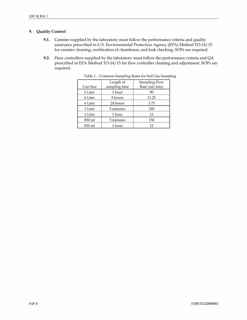
SOP 18, REV. 1
6 OF 8 ES081312222904BAO
9. Quality Control
9.1. Canister supplied by the laboratory must follow the performance criteria and quality assurance prescribed in U.S. Environmental Protection Agency (EPA) Method TO-14/15 for canister cleaning, certification of cleanliness, and leak checking. SOPs are required.
9.2. Flow controllers supplied by the laboratory must follow the performance criteria and QA prescribed in EPA Method TO-14/15 for flow controller cleaning and adjustment. SOPs are required.
Table 1 – Common Sampling Rates for Soil Gas Sampling
Can Size Length of
sampling time Sampling Flow Rate (ml/min)
6 Liter 1 hour 90 6 Liter 8 hours 11.25 6 Liter 24 hours 3.75 1 Liter 5 minutes 180 1 Liter 1 hour 15 850 ml 5 minutes 150
850 ml 1 hour 12
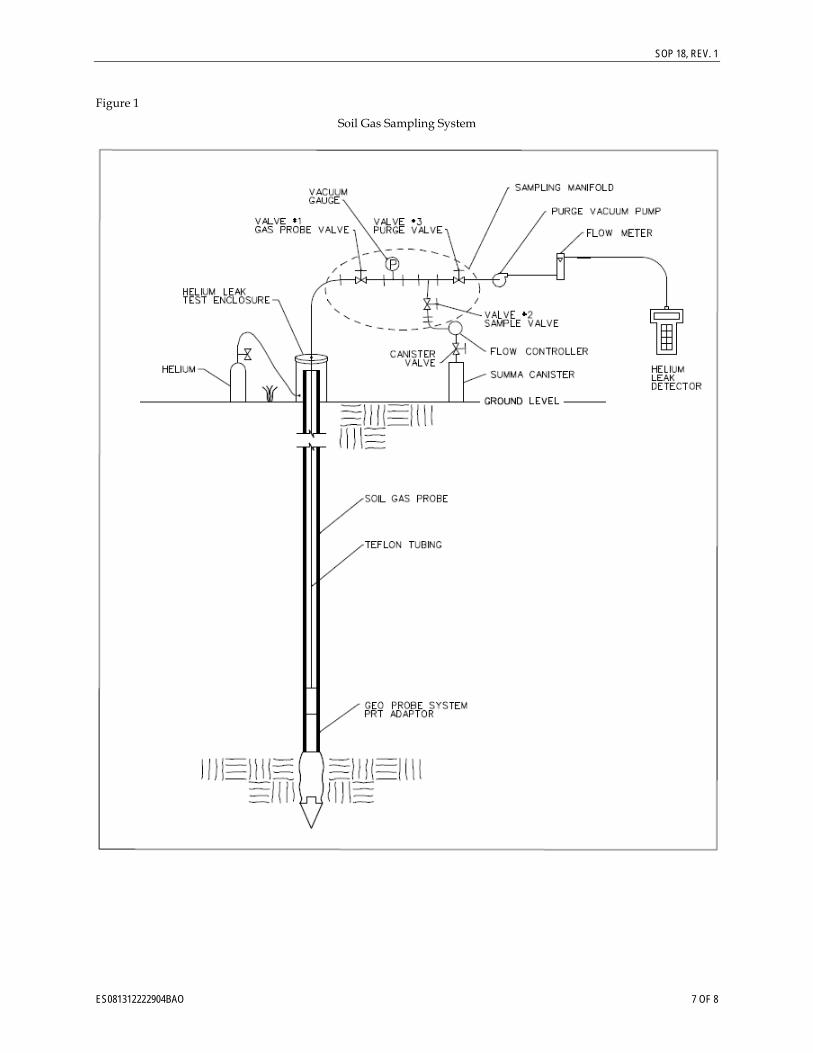
SOP 18, REV. 1
ES081312222904BAO 7 OF 8
Figure 1
Soil Gas Sampling System
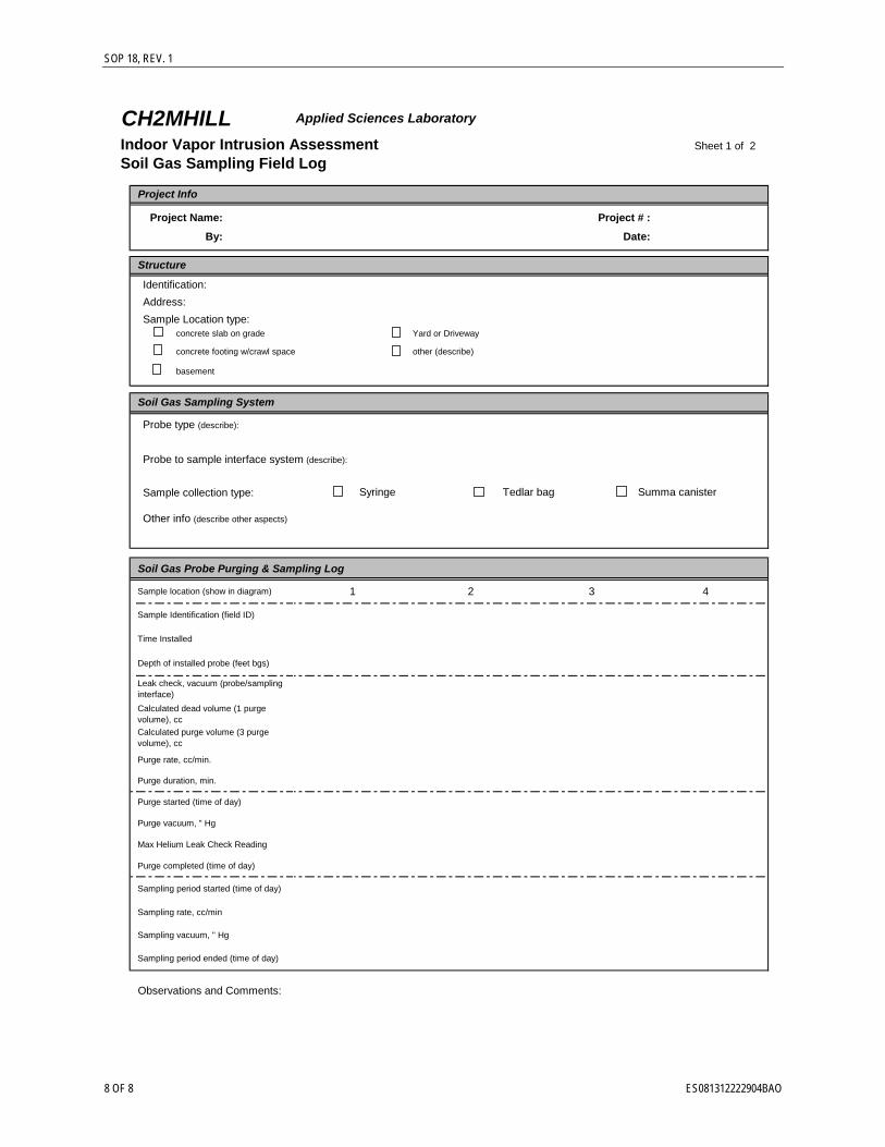
SOP 18, REV. 1
8 OF 8 ES081312222904BAO
CH2MHILL Applied Sciences Laboratory
Indoor Vapor Intrusion Assessment Sheet 1 of 2
Soil Gas Sampling Field Log
Project # :
Date:
Identification: Address:Sample Location type:
concrete slab on grade Yard or Driveway
concrete footing w/crawl space other (describe)
basement
Probe type (describe):
Probe to sample interface system (describe):
Sample collection type:
Other info (describe other aspects)
Soil Gas Probe Purging & Sampling Log
1 4
Observations and Comments:
Sample Identification (field ID)
Sample location (show in diagram)
Sampling period started (time of day)
Purge completed (time of day)
Purge vacuum, " Hg
Purge duration, min.
Purge rate, cc/min.
Calculated dead volume (1 purge volume), cc
Leak check, vacuum (probe/sampling interface)
Max Helium Leak Check Reading
Sampling period ended (time of day)
Sampling vacuum, " Hg
Sampling rate, cc/min
Summa canister
2 3
Syringe Tedlar bag
Project Info
Project Name:
By:
Structure
Soil Gas Sampling System
Time Installed
Depth of installed probe (feet bgs)
Calculated purge volume (3 purge volume), cc
Purge started (time of day)
Appendix B Management Protocol for Handling and Disposition
of Displaced Site Material

SFO\122410001 (DISPLACED MATERIAL MEMO--DRAFT 12-17-12) 1 ES051412033345BAO
Management Protocol for Handling and Disposition of Displaced Site Material, Topock Remediation Project, Needles, California PREPARED FOR: Topock Remediation Project Files PREPARED BY: Pacific Gas and Electric Company DATE: October 3, 2012
This document presents the general approach and management protocol required for the handling and disposition of soil and/or rock (referred to as “material” throughout the document) that is displaced as a result of past (as practical), present, and future activities associated with the Pacific Gas and Electric Company (PG&E) Topock Remediation Project, Needles, California. Specifically, this includes material removed from the Earth (i.e., displaced) as a result of drilling, excavation, sampling, testing, construction, grading, and other remedial activities. The management of material that may be disturbed as a result of remedial activities but not displaced from its natural location, such as soil disturbed by foot or vehicle traffic along a pathway, is not within the scope of this protocol. This protocol is applicable to the handling and disposition of displaced materials only. Further, materials that were not part of the natural site condition (e.g., building materials, equipment, waste, debris, or imported fill1) are not included in this protocol.
1.0 Introduction PG&E carefully plans Topock Remediation Project activities to minimize both the disturbance and displacement of site material. The land and soils are to be handled and managed with care and respect. Therefore, the protocol established in this plan is intended to minimize the amount of displaced material that leaves the site and instead, provide for eventual return, reuse, or restoration of the material onto the lands from which it was displaced. Through the application of this protocol and its incorporation into future work plans involving material displacement, it is anticipated that the goal of careful and respectful handling of soil material will be fulfilled.
In addition to addressing Tribal requests, this protocol was developed to comply with Mitigation Measure CUL‐1a‐8 as set forth in the certified Environmental Impact Report (EIR) and Mitigation Monitoring and Reporting Plan (MMRP) adopted by the California Department of Toxic Substances Control (DTSC). This measure requires PG&E to develop a Cultural Impact Mitigation Program (CIMP) as part of the final design of the approved groundwater remedy, and specifically subparagraph (g) requires the CIMP to include protocols for handling soil cuttings2. DTSC adopted this measure following its determination that the project area is a significant historical resource for California Environmental Quality Act (CEQA) purposes (Final EIR, p. 4.4‐57). Similarly, as part of the consultation process for the Programmatic Agreement (PA) under Section 106 of the National Historic Preservation Act (NHPA), the U.S. Bureau of Land Management (BLM) determined that a traditional cultural property (TCP) eligible for inclusion on the National Register of Historic Places exists within the Area of Potential Effect (APE). Throughout this document, the term “site” refers to the area within the APE.
1 For the purpose of this protocol, imported fill is defined as unconsolidated mixtures of sand, silt, and gravel (engineered gradations, or otherwise) that were not originally derived from inside the defined project boundary. Specific examples of imported fill material may include road base material, shading material used in pipeline trenches, or crushed rock used for railroad ballast.
2 Mitigation Measure CUL‐1a‐8(g) states the following: Protocols for the repatriation of clean soil cuttings generated during construction activities and during drilling associated with repair/replacement activities during operations and maintenance phases. The soil cuttings shall be managed in compliance with applicable laws and regulations on site.
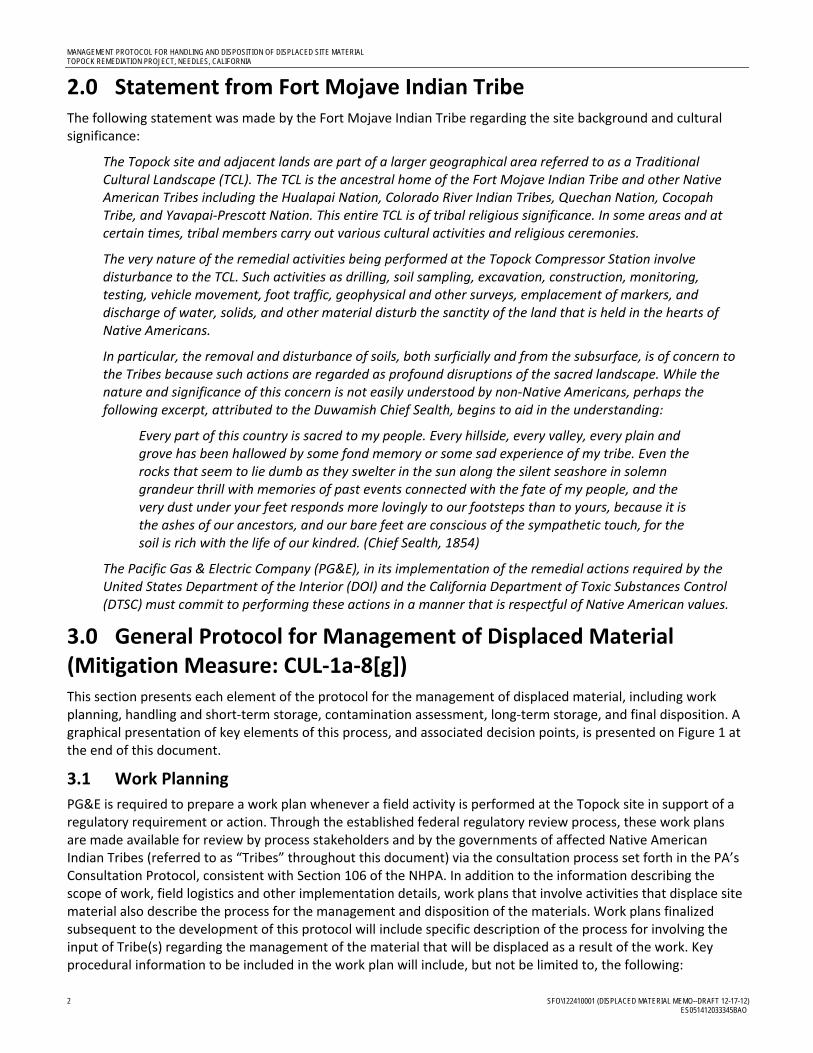
MANAGEMENT PROTOCOL FOR HANDLING AND DISPOSITION OF DISPLACED SITE MATERIAL TOPOCK REMEDIATION PROJECT, NEEDLES, CALIFORNIA
2 SFO\122410001 (DISPLACED MATERIAL MEMO--DRAFT 12-17-12) ES051412033345BAO
2.0 Statement from Fort Mojave Indian Tribe The following statement was made by the Fort Mojave Indian Tribe regarding the site background and cultural significance:
The Topock site and adjacent lands are part of a larger geographical area referred to as a Traditional Cultural Landscape (TCL). The TCL is the ancestral home of the Fort Mojave Indian Tribe and other Native American Tribes including the Hualapai Nation, Colorado River Indian Tribes, Quechan Nation, Cocopah Tribe, and Yavapai‐Prescott Nation. This entire TCL is of tribal religious significance. In some areas and at certain times, tribal members carry out various cultural activities and religious ceremonies.
The very nature of the remedial activities being performed at the Topock Compressor Station involve disturbance to the TCL. Such activities as drilling, soil sampling, excavation, construction, monitoring, testing, vehicle movement, foot traffic, geophysical and other surveys, emplacement of markers, and discharge of water, solids, and other material disturb the sanctity of the land that is held in the hearts of Native Americans.
In particular, the removal and disturbance of soils, both surficially and from the subsurface, is of concern to the Tribes because such actions are regarded as profound disruptions of the sacred landscape. While the nature and significance of this concern is not easily understood by non‐Native Americans, perhaps the following excerpt, attributed to the Duwamish Chief Sealth, begins to aid in the understanding:
Every part of this country is sacred to my people. Every hillside, every valley, every plain and grove has been hallowed by some fond memory or some sad experience of my tribe. Even the rocks that seem to lie dumb as they swelter in the sun along the silent seashore in solemn grandeur thrill with memories of past events connected with the fate of my people, and the very dust under your feet responds more lovingly to our footsteps than to yours, because it is the ashes of our ancestors, and our bare feet are conscious of the sympathetic touch, for the soil is rich with the life of our kindred. (Chief Sealth, 1854)
The Pacific Gas & Electric Company (PG&E), in its implementation of the remedial actions required by the United States Department of the Interior (DOI) and the California Department of Toxic Substances Control (DTSC) must commit to performing these actions in a manner that is respectful of Native American values.
3.0 General Protocol for Management of Displaced Material (Mitigation Measure: CUL‐1a‐8[g]) This section presents each element of the protocol for the management of displaced material, including work planning, handling and short‐term storage, contamination assessment, long‐term storage, and final disposition. A graphical presentation of key elements of this process, and associated decision points, is presented on Figure 1 at the end of this document.
3.1 Work Planning
PG&E is required to prepare a work plan whenever a field activity is performed at the Topock site in support of a regulatory requirement or action. Through the established federal regulatory review process, these work plans are made available for review by process stakeholders and by the governments of affected Native American Indian Tribes (referred to as “Tribes” throughout this document) via the consultation process set forth in the PA’s Consultation Protocol, consistent with Section 106 of the NHPA. In addition to the information describing the scope of work, field logistics and other implementation details, work plans that involve activities that displace site material also describe the process for the management and disposition of the materials. Work plans finalized subsequent to the development of this protocol will include specific description of the process for involving the input of Tribe(s) regarding the management of the material that will be displaced as a result of the work. Key procedural information to be included in the work plan will include, but not be limited to, the following:
MANAGEMENT PROTOCOL FOR HANDLING AND DISPOSITION OF DISPLACED SITE MATERIAL TOPOCK REMEDIATION PROJECT, NEEDLES, CALIFORNIA
SFO\122410001 (DISPLACED MATERIAL MEMO--DRAFT 12-17-12) 3 ES051412033345BAO
Summary of measures planned to minimize the amount of disturbance that will be incurred.
Notification procedures to inform the Tribe(s), involved regulatory agencies, and affected land owner(s) regarding the proposed activities that will disturb/displace soil or other materials.
The location of proposed disturbance activities (e.g. access pathways) and displacement activities (e.g. drilling or sampling locations), including maps.
Estimation of the volume and type(s) of material that will be displaced.
The location and methodology for short‐term storage of displaced material (see Section 3.2).
Methods that will be used to assess whether contaminants are present (see Section 3.3).
Methods that will be used to minimize the volume of material that may require long‐term storage (see Section 3.4).
The location and methodology for long‐term storage (see Section 3.4).
The anticipated location and methodology for final on‐site disposition (see Section 3.5).
3.2 Handling and Short‐term Storage
Material that is displaced as a result of Topock Remediation Project activities including drilling, excavation, sample collection, testing, construction, grading, or other activities will be handled on‐site in accordance with the project‐specific work plan. Displaced material that must be characterized for key chemical properties prior to identifying the appropriate final disposition method will be stored for the short term. Short‐term storage areas and the protocol for handing material in these areas may vary by project. Depending on the type and volume of material displaced, location, land owner considerations, and other pertinent factors, short‐term storage methods may include storage devices (e.g. bins) or properly maintained stockpiles that prevent this material from commingling with other areas of the environment. In some cases, short‐term storage for characterization may not be necessary. For example, displaced material that is pre‐characterized or characterized rapidly as work is conducted will be managed directly for long‐term storage or final disposition, as appropriate (see Sections 3.4 and 3.5, respectively).
Specific material handling and short‐term storage details will be defined in the approved work plan for a given activity. Key details to be identified in the work plan include:
The mode and location of short‐term storage.
The method of transfer from the point of origin to short‐term staging area.
Best management practices/regulatory requirements to prevent releases of the potentially contaminated material during transfer and storage.
Best management practices to protect the material from weather, erosion, contamination, and vandalism while located in the short‐term staging area(s).
Method for segregation of soils based by location, as practicable and appropriate.
A key element of this handling protocol is the development of an inventory of all material displaced by Topock Remediation Project activities. Key information maintained in this inventory will include:
Material displacement authorization – Specific work plan under which the work was conducted.
Material origin – Specific location of the site.
Material description (e.g., soil, rock, etc.).
Date(s) of displacement or accumulation.
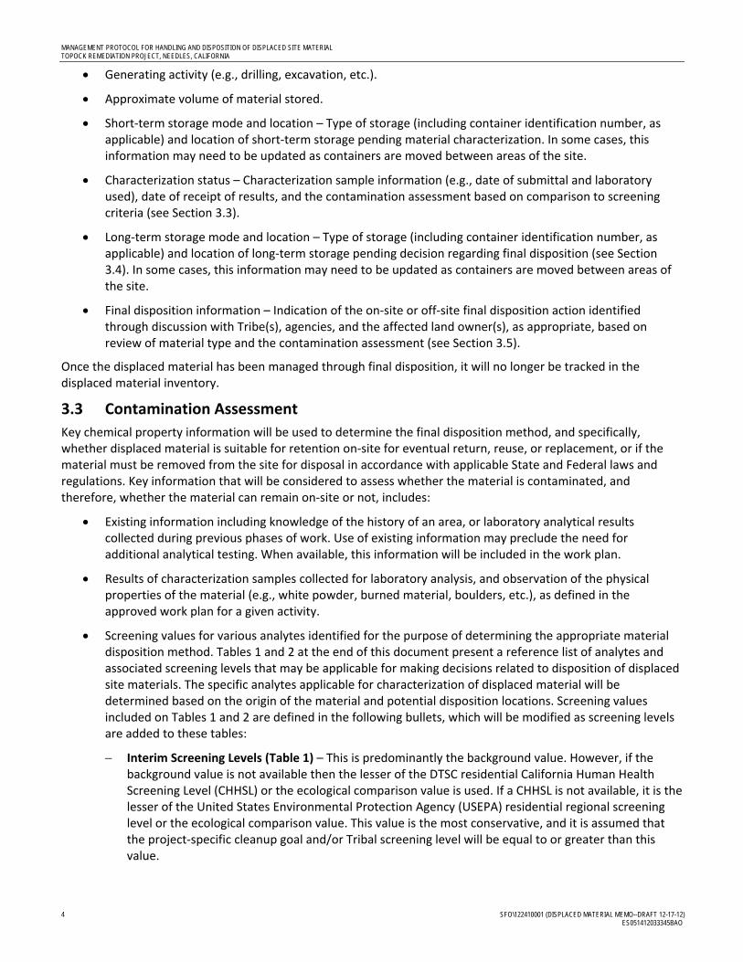
MANAGEMENT PROTOCOL FOR HANDLING AND DISPOSITION OF DISPLACED SITE MATERIAL TOPOCK REMEDIATION PROJECT, NEEDLES, CALIFORNIA
4 SFO\122410001 (DISPLACED MATERIAL MEMO--DRAFT 12-17-12) ES051412033345BAO
Generating activity (e.g., drilling, excavation, etc.).
Approximate volume of material stored.
Short‐term storage mode and location – Type of storage (including container identification number, as applicable) and location of short‐term storage pending material characterization. In some cases, this information may need to be updated as containers are moved between areas of the site.
Characterization status – Characterization sample information (e.g., date of submittal and laboratory used), date of receipt of results, and the contamination assessment based on comparison to screening criteria (see Section 3.3).
Long‐term storage mode and location – Type of storage (including container identification number, as applicable) and location of long‐term storage pending decision regarding final disposition (see Section 3.4). In some cases, this information may need to be updated as containers are moved between areas of the site.
Final disposition information – Indication of the on‐site or off‐site final disposition action identified through discussion with Tribe(s), agencies, and the affected land owner(s), as appropriate, based on review of material type and the contamination assessment (see Section 3.5).
Once the displaced material has been managed through final disposition, it will no longer be tracked in the displaced material inventory.
3.3 Contamination Assessment
Key chemical property information will be used to determine the final disposition method, and specifically, whether displaced material is suitable for retention on‐site for eventual return, reuse, or replacement, or if the material must be removed from the site for disposal in accordance with applicable State and Federal laws and regulations. Key information that will be considered to assess whether the material is contaminated, and therefore, whether the material can remain on‐site or not, includes:
Existing information including knowledge of the history of an area, or laboratory analytical results collected during previous phases of work. Use of existing information may preclude the need for additional analytical testing. When available, this information will be included in the work plan.
Results of characterization samples collected for laboratory analysis, and observation of the physical properties of the material (e.g., white powder, burned material, boulders, etc.), as defined in the approved work plan for a given activity.
Screening values for various analytes identified for the purpose of determining the appropriate material disposition method. Tables 1 and 2 at the end of this document present a reference list of analytes and associated screening levels that may be applicable for making decisions related to disposition of displaced site materials. The specific analytes applicable for characterization of displaced material will be determined based on the origin of the material and potential disposition locations. Screening values included on Tables 1 and 2 are defined in the following bullets, which will be modified as screening levels are added to these tables:
Interim Screening Levels (Table 1) – This is predominantly the background value. However, if the background value is not available then the lesser of the DTSC residential California Human Health Screening Level (CHHSL) or the ecological comparison value is used. If a CHHSL is not available, it is the lesser of the United States Environmental Protection Agency (USEPA) residential regional screening level or the ecological comparison value. This value is the most conservative, and it is assumed that the project‐specific cleanup goal and/or Tribal screening level will be equal to or greater than this value.
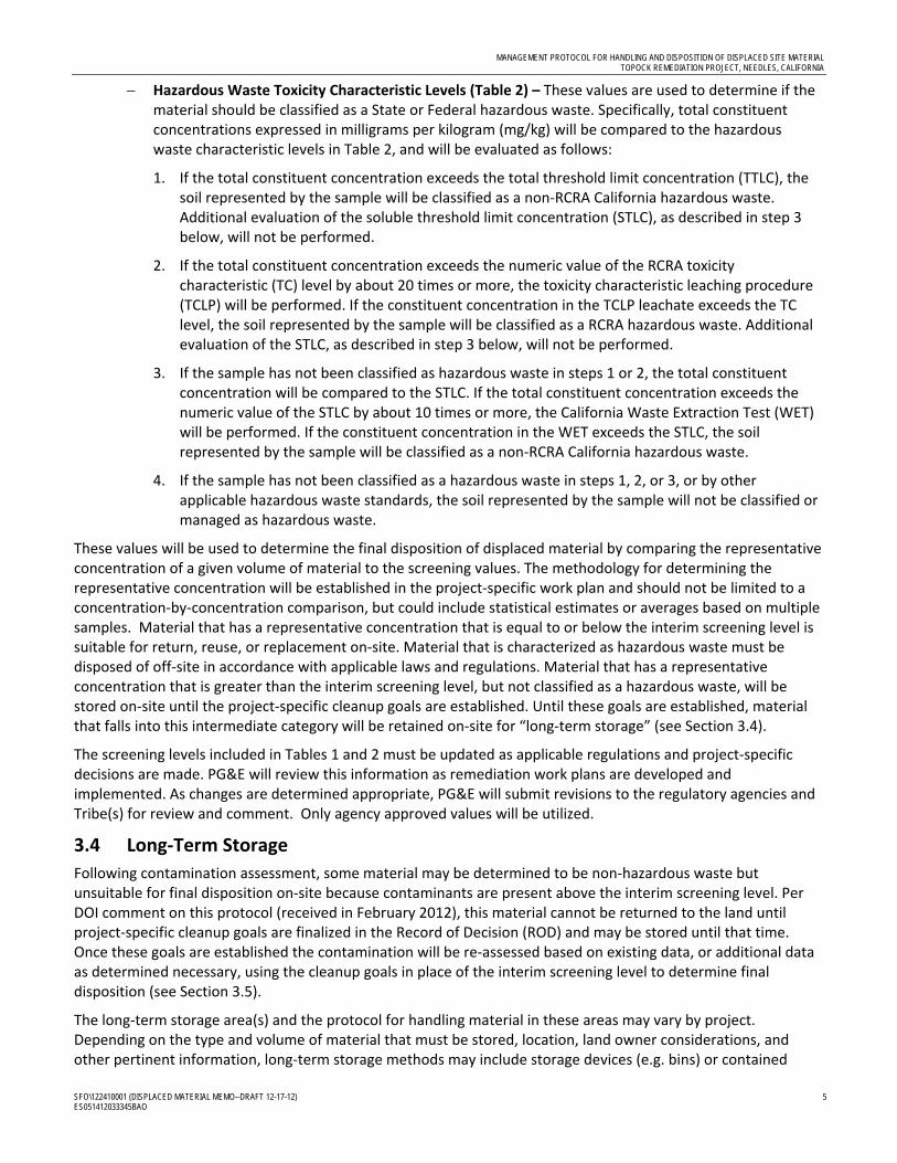
MANAGEMENT PROTOCOL FOR HANDLING AND DISPOSITION OF DISPLACED SITE MATERIAL TOPOCK REMEDIATION PROJECT, NEEDLES, CALIFORNIA
SFO\122410001 (DISPLACED MATERIAL MEMO--DRAFT 12-17-12) 5 ES051412033345BAO
Hazardous Waste Toxicity Characteristic Levels (Table 2) – These values are used to determine if the material should be classified as a State or Federal hazardous waste. Specifically, total constituent concentrations expressed in milligrams per kilogram (mg/kg) will be compared to the hazardous waste characteristic levels in Table 2, and will be evaluated as follows:
1. If the total constituent concentration exceeds the total threshold limit concentration (TTLC), the soil represented by the sample will be classified as a non‐RCRA California hazardous waste. Additional evaluation of the soluble threshold limit concentration (STLC), as described in step 3 below, will not be performed.
2. If the total constituent concentration exceeds the numeric value of the RCRA toxicity characteristic (TC) level by about 20 times or more, the toxicity characteristic leaching procedure (TCLP) will be performed. If the constituent concentration in the TCLP leachate exceeds the TC level, the soil represented by the sample will be classified as a RCRA hazardous waste. Additional evaluation of the STLC, as described in step 3 below, will not be performed.
3. If the sample has not been classified as hazardous waste in steps 1 or 2, the total constituent concentration will be compared to the STLC. If the total constituent concentration exceeds the numeric value of the STLC by about 10 times or more, the California Waste Extraction Test (WET) will be performed. If the constituent concentration in the WET exceeds the STLC, the soil represented by the sample will be classified as a non‐RCRA California hazardous waste.
4. If the sample has not been classified as a hazardous waste in steps 1, 2, or 3, or by other applicable hazardous waste standards, the soil represented by the sample will not be classified or managed as hazardous waste.
These values will be used to determine the final disposition of displaced material by comparing the representative concentration of a given volume of material to the screening values. The methodology for determining the representative concentration will be established in the project‐specific work plan and should not be limited to a concentration‐by‐concentration comparison, but could include statistical estimates or averages based on multiple samples. Material that has a representative concentration that is equal to or below the interim screening level is suitable for return, reuse, or replacement on‐site. Material that is characterized as hazardous waste must be disposed of off‐site in accordance with applicable laws and regulations. Material that has a representative concentration that is greater than the interim screening level, but not classified as a hazardous waste, will be stored on‐site until the project‐specific cleanup goals are established. Until these goals are established, material that falls into this intermediate category will be retained on‐site for “long‐term storage” (see Section 3.4).
The screening levels included in Tables 1 and 2 must be updated as applicable regulations and project‐specific decisions are made. PG&E will review this information as remediation work plans are developed and implemented. As changes are determined appropriate, PG&E will submit revisions to the regulatory agencies and Tribe(s) for review and comment. Only agency approved values will be utilized.
3.4 Long‐Term Storage
Following contamination assessment, some material may be determined to be non‐hazardous waste but unsuitable for final disposition on‐site because contaminants are present above the interim screening level. Per DOI comment on this protocol (received in February 2012), this material cannot be returned to the land until project‐specific cleanup goals are finalized in the Record of Decision (ROD) and may be stored until that time. Once these goals are established the contamination will be re‐assessed based on existing data, or additional data as determined necessary, using the cleanup goals in place of the interim screening level to determine final disposition (see Section 3.5).
The long‐term storage area(s) and the protocol for handling material in these areas may vary by project. Depending on the type and volume of material that must be stored, location, land owner considerations, and other pertinent information, long‐term storage methods may include storage devices (e.g. bins) or contained
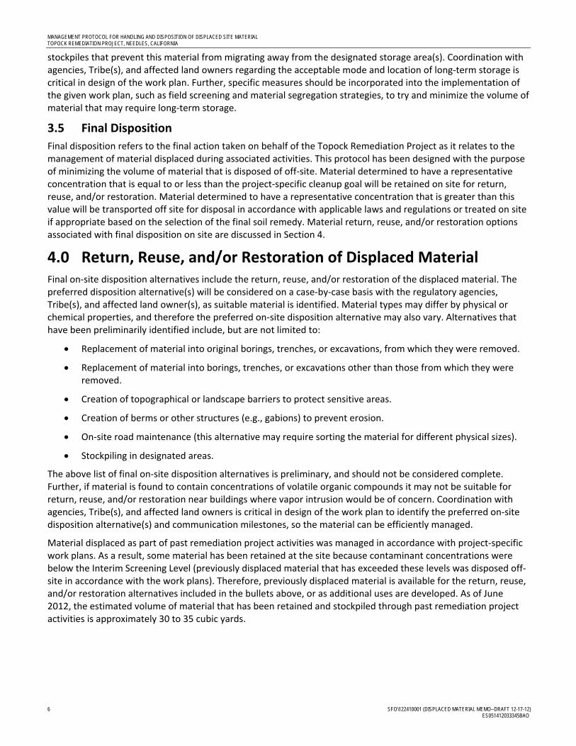
MANAGEMENT PROTOCOL FOR HANDLING AND DISPOSITION OF DISPLACED SITE MATERIAL TOPOCK REMEDIATION PROJECT, NEEDLES, CALIFORNIA
6 SFO\122410001 (DISPLACED MATERIAL MEMO--DRAFT 12-17-12) ES051412033345BAO
stockpiles that prevent this material from migrating away from the designated storage area(s). Coordination with agencies, Tribe(s), and affected land owners regarding the acceptable mode and location of long‐term storage is critical in design of the work plan. Further, specific measures should be incorporated into the implementation of the given work plan, such as field screening and material segregation strategies, to try and minimize the volume of material that may require long‐term storage.
3.5 Final Disposition
Final disposition refers to the final action taken on behalf of the Topock Remediation Project as it relates to the management of material displaced during associated activities. This protocol has been designed with the purpose of minimizing the volume of material that is disposed of off‐site. Material determined to have a representative concentration that is equal to or less than the project‐specific cleanup goal will be retained on site for return, reuse, and/or restoration. Material determined to have a representative concentration that is greater than this value will be transported off site for disposal in accordance with applicable laws and regulations or treated on site if appropriate based on the selection of the final soil remedy. Material return, reuse, and/or restoration options associated with final disposition on site are discussed in Section 4.
4.0 Return, Reuse, and/or Restoration of Displaced Material Final on‐site disposition alternatives include the return, reuse, and/or restoration of the displaced material. The preferred disposition alternative(s) will be considered on a case‐by‐case basis with the regulatory agencies, Tribe(s), and affected land owner(s), as suitable material is identified. Material types may differ by physical or chemical properties, and therefore the preferred on‐site disposition alternative may also vary. Alternatives that have been preliminarily identified include, but are not limited to:
Replacement of material into original borings, trenches, or excavations, from which they were removed.
Replacement of material into borings, trenches, or excavations other than those from which they were removed.
Creation of topographical or landscape barriers to protect sensitive areas.
Creation of berms or other structures (e.g., gabions) to prevent erosion.
On‐site road maintenance (this alternative may require sorting the material for different physical sizes).
Stockpiling in designated areas.
The above list of final on‐site disposition alternatives is preliminary, and should not be considered complete. Further, if material is found to contain concentrations of volatile organic compounds it may not be suitable for return, reuse, and/or restoration near buildings where vapor intrusion would be of concern. Coordination with agencies, Tribe(s), and affected land owners is critical in design of the work plan to identify the preferred on‐site disposition alternative(s) and communication milestones, so the material can be efficiently managed.
Material displaced as part of past remediation project activities was managed in accordance with project‐specific work plans. As a result, some material has been retained at the site because contaminant concentrations were below the Interim Screening Level (previously displaced material that has exceeded these levels was disposed off‐site in accordance with the work plans). Therefore, previously displaced material is available for the return, reuse, and/or restoration alternatives included in the bullets above, or as additional uses are developed. As of June 2012, the estimated volume of material that has been retained and stockpiled through past remediation project activities is approximately 30 to 35 cubic yards.
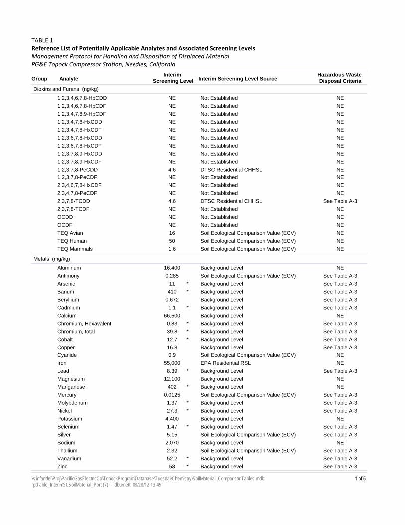
Interim Screening Level SourceInterim
Screening LevelAnalyteGroup
TABLE 1Reference List of Potentially Applicable Analytes and Associated Screening Levels
PG&E Topock Compressor Station, Needles, California
Hazardous Waste Disposal Criteria
Management Protocol for Handling and Disposition of Displaced Material
Dioxins and Furans (ng/kg)
Not EstablishedNE1,2,3,4,6,7,8-HpCDD NE
Not EstablishedNE1,2,3,4,6,7,8-HpCDF NE
Not EstablishedNE1,2,3,4,7,8,9-HpCDF NE
Not EstablishedNE1,2,3,4,7,8-HxCDD NE
Not EstablishedNE1,2,3,4,7,8-HxCDF NE
Not EstablishedNE1,2,3,6,7,8-HxCDD NE
Not EstablishedNE1,2,3,6,7,8-HxCDF NE
Not EstablishedNE1,2,3,7,8,9-HxCDD NE
Not EstablishedNE1,2,3,7,8,9-HxCDF NE
DTSC Residential CHHSL4.61,2,3,7,8-PeCDD NE
Not EstablishedNE1,2,3,7,8-PeCDF NE
Not EstablishedNE2,3,4,6,7,8-HxCDF NE
Not EstablishedNE2,3,4,7,8-PeCDF NE
DTSC Residential CHHSL4.62,3,7,8-TCDD See Table A-3
Not EstablishedNE2,3,7,8-TCDF NE
Not EstablishedNEOCDD NE
Not EstablishedNEOCDF NE
Soil Ecological Comparison Value (ECV)16TEQ Avian NE
Soil Ecological Comparison Value (ECV)50TEQ Human NE
Soil Ecological Comparison Value (ECV)1.6TEQ Mammals NE
Metals (mg/kg)
Background Level16,400Aluminum NE
Soil Ecological Comparison Value (ECV)0.285Antimony See Table A-3
Background Level11Arsenic See Table A-3*
Background Level410Barium See Table A-3*
Background Level0.672Beryllium See Table A-3
Background Level1.1Cadmium See Table A-3*
Background Level66,500Calcium NE
Background Level0.83Chromium, Hexavalent See Table A-3*
Background Level39.8Chromium, total See Table A-3*
Background Level12.7Cobalt See Table A-3*
Background Level16.8Copper See Table A-3
Soil Ecological Comparison Value (ECV)0.9Cyanide NE
EPA Residential RSL55,000Iron NE
Background Level8.39Lead See Table A-3*
Background Level12,100Magnesium NE
Background Level402Manganese NE*
Soil Ecological Comparison Value (ECV)0.0125Mercury See Table A-3
Background Level1.37Molybdenum See Table A-3*
Background Level27.3Nickel See Table A-3*
Background Level4,400Potassium NE
Background Level1.47Selenium See Table A-3*
Soil Ecological Comparison Value (ECV)5.15Silver See Table A-3
Background Level2,070Sodium NE
Soil Ecological Comparison Value (ECV)2.32Thallium See Table A-3
Background Level52.2Vanadium See Table A-3*
Background Level58Zinc See Table A-3*
1 of 6\\zinfandel\Proj\PacificGasElectricCo\TopockProgram\Database\Tuesdai\Chemistry\SoilMaterial_ComparisonTables.mdb: rptTable_InterimSLSoilMaterial_Port (7) - dburnett 08/28/12 13:49
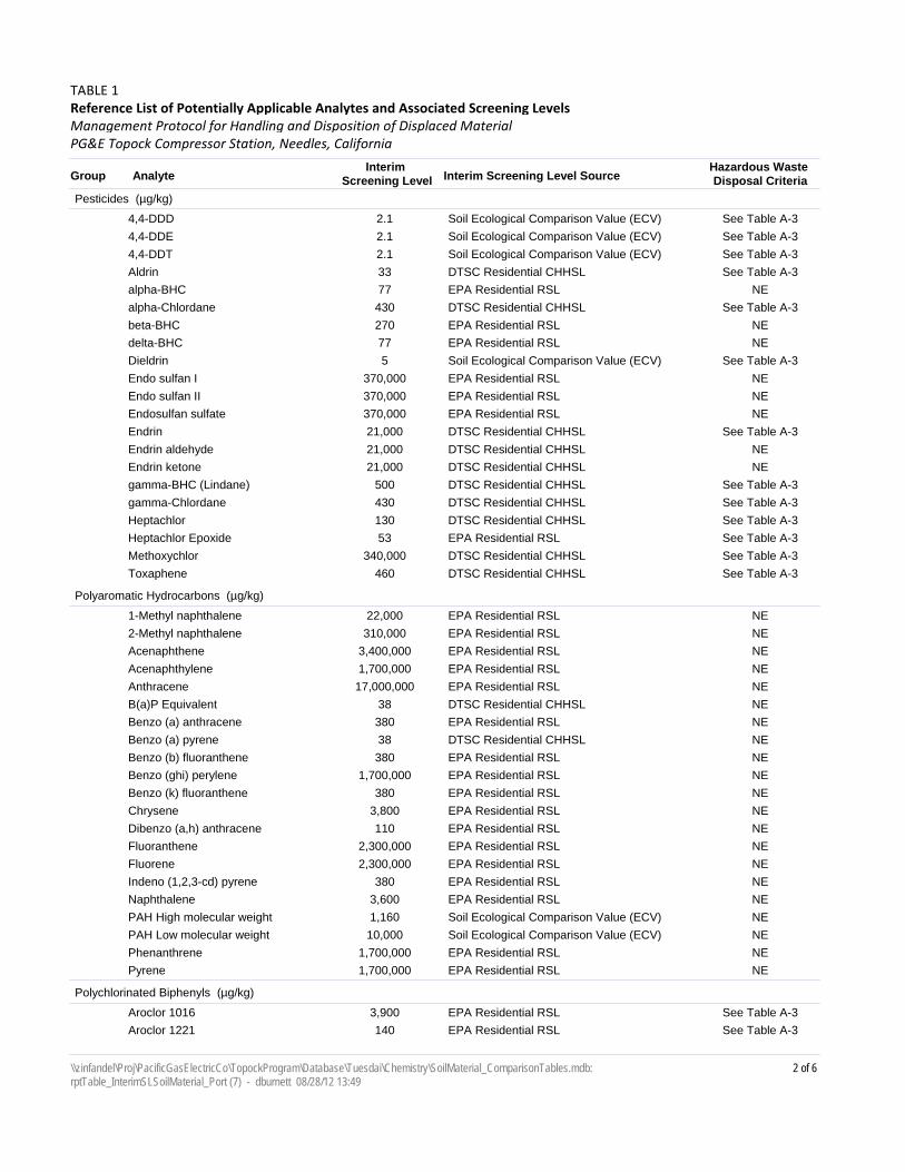
Interim Screening Level SourceInterim
Screening LevelAnalyteGroup
TABLE 1Reference List of Potentially Applicable Analytes and Associated Screening Levels
PG&E Topock Compressor Station, Needles, California
Hazardous Waste Disposal Criteria
Management Protocol for Handling and Disposition of Displaced Material
Pesticides (µg/kg)
Soil Ecological Comparison Value (ECV)2.14,4-DDD See Table A-3
Soil Ecological Comparison Value (ECV)2.14,4-DDE See Table A-3
Soil Ecological Comparison Value (ECV)2.14,4-DDT See Table A-3
DTSC Residential CHHSL33Aldrin See Table A-3
EPA Residential RSL77alpha-BHC NE
DTSC Residential CHHSL430alpha-Chlordane See Table A-3
EPA Residential RSL270beta-BHC NE
EPA Residential RSL77delta-BHC NE
Soil Ecological Comparison Value (ECV)5Dieldrin See Table A-3
EPA Residential RSL370,000Endo sulfan I NE
EPA Residential RSL370,000Endo sulfan II NE
EPA Residential RSL370,000Endosulfan sulfate NE
DTSC Residential CHHSL21,000Endrin See Table A-3
DTSC Residential CHHSL21,000Endrin aldehyde NE
DTSC Residential CHHSL21,000Endrin ketone NE
DTSC Residential CHHSL500gamma-BHC (Lindane) See Table A-3
DTSC Residential CHHSL430gamma-Chlordane See Table A-3
DTSC Residential CHHSL130Heptachlor See Table A-3
EPA Residential RSL53Heptachlor Epoxide See Table A-3
DTSC Residential CHHSL340,000Methoxychlor See Table A-3
DTSC Residential CHHSL460Toxaphene See Table A-3
Polyaromatic Hydrocarbons (µg/kg)
EPA Residential RSL22,0001-Methyl naphthalene NE
EPA Residential RSL310,0002-Methyl naphthalene NE
EPA Residential RSL3,400,000Acenaphthene NE
EPA Residential RSL1,700,000Acenaphthylene NE
EPA Residential RSL17,000,000Anthracene NE
DTSC Residential CHHSL38B(a)P Equivalent NE
EPA Residential RSL380Benzo (a) anthracene NE
DTSC Residential CHHSL38Benzo (a) pyrene NE
EPA Residential RSL380Benzo (b) fluoranthene NE
EPA Residential RSL1,700,000Benzo (ghi) perylene NE
EPA Residential RSL380Benzo (k) fluoranthene NE
EPA Residential RSL3,800Chrysene NE
EPA Residential RSL110Dibenzo (a,h) anthracene NE
EPA Residential RSL2,300,000Fluoranthene NE
EPA Residential RSL2,300,000Fluorene NE
EPA Residential RSL380Indeno (1,2,3-cd) pyrene NE
EPA Residential RSL3,600Naphthalene NE
Soil Ecological Comparison Value (ECV)1,160PAH High molecular weight NE
Soil Ecological Comparison Value (ECV)10,000PAH Low molecular weight NE
EPA Residential RSL1,700,000Phenanthrene NE
EPA Residential RSL1,700,000Pyrene NE
Polychlorinated Biphenyls (µg/kg)
EPA Residential RSL3,900Aroclor 1016 See Table A-3
EPA Residential RSL140Aroclor 1221 See Table A-3
2 of 6\\zinfandel\Proj\PacificGasElectricCo\TopockProgram\Database\Tuesdai\Chemistry\SoilMaterial_ComparisonTables.mdb: rptTable_InterimSLSoilMaterial_Port (7) - dburnett 08/28/12 13:49
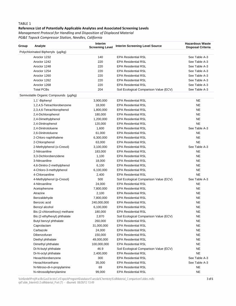
Interim Screening Level SourceInterim
Screening LevelAnalyteGroup
TABLE 1Reference List of Potentially Applicable Analytes and Associated Screening Levels
PG&E Topock Compressor Station, Needles, California
Hazardous Waste Disposal Criteria
Management Protocol for Handling and Disposition of Displaced Material
Polychlorinated Biphenyls (µg/kg)
EPA Residential RSL140Aroclor 1232 See Table A-3
EPA Residential RSL220Aroclor 1242 See Table A-3
EPA Residential RSL220Aroclor 1248 See Table A-3
EPA Residential RSL220Aroclor 1254 See Table A-3
EPA Residential RSL220Aroclor 1260 See Table A-3
EPA Residential RSL220Aroclor 1262 See Table A-3
EPA Residential RSL220Aroclor 1268 See Table A-3
Soil Ecological Comparison Value (ECV)204Total PCBs See Table A-3
Semivolatile Organic Compounds (µg/kg)
EPA Residential RSL3,900,0001,1´-Biphenyl NE
EPA Residential RSL18,0001,2,4,5-Tetrachlorobenzene NE
EPA Residential RSL1,800,0002,3,4,6-Tetrachlorophenol NE
EPA Residential RSL180,0002,4-Dichlorophenol NE
EPA Residential RSL1,200,0002,4-Dimethylphenol NE
EPA Residential RSL120,0002,4-Dinitrophenol NE
EPA Residential RSL1,6002,4-Dinitrotoluene See Table A-3
EPA Residential RSL61,0002,6-Dinitrotoluene NE
EPA Residential RSL6,300,0002-Chloro naphthalene NE
EPA Residential RSL63,0002-Chlorophenol NE
EPA Residential RSL3,100,0002-Methylphenol (o-Cresol) See Table A-3
EPA Residential RSL183,0002-Nitroaniline NE
EPA Residential RSL1,1003,3-Dichlorobenzidene NE
EPA Residential RSL18,0003-Nitroaniline NE
EPA Residential RSL6,1004,6-Dinitro-2-methylphenol NE
EPA Residential RSL6,100,0004-Chloro-3-methylphenol NE
EPA Residential RSL2,4004-Chloroaniline NE
Soil Ecological Comparison Value (ECV)5004-Methylphenol (p-Cresol) See Table A-3
EPA Residential RSL24,0004-Nitroaniline NE
EPA Residential RSL7,800,000Acetophenone NE
EPA Residential RSL2,100Atrazine NE
EPA Residential RSL7,800,000Benzaldehyde NE
EPA Residential RSL240,000,000Benzoic acid NE
EPA Residential RSL6,100,000Benzyl alcohol NE
EPA Residential RSL180,000Bis (2-chloroethoxy) methane NE
Soil Ecological Comparison Value (ECV)2,870Bis (2-ethylhexyl) phthalate NE
EPA Residential RSL260,000Butyl benzyl phthalate NE
EPA Residential RSL31,000,000Caprolactam NE
EPA Residential RSL24,000Carbazole NE
EPA Residential RSL150,000Dibenzofuran NE
EPA Residential RSL49,000,000Diethyl phthalate NE
EPA Residential RSL100,000,000Dimethyl phthalate NE
Soil Ecological Comparison Value (ECV)46.9Di-N-butyl phthalate NE
EPA Residential RSL2,400,000Di-N-octyl phthalate NE
EPA Residential RSL300Hexachlorobenzene See Table A-3
EPA Residential RSL35,000Hexachloroethane See Table A-3
EPA Residential RSL69N-Nitroso-di-n-propylamine NE
EPA Residential RSL99,000N-nitrosodiphenylamine NE
3 of 6\\zinfandel\Proj\PacificGasElectricCo\TopockProgram\Database\Tuesdai\Chemistry\SoilMaterial_ComparisonTables.mdb: rptTable_InterimSLSoilMaterial_Port (7) - dburnett 08/28/12 13:49
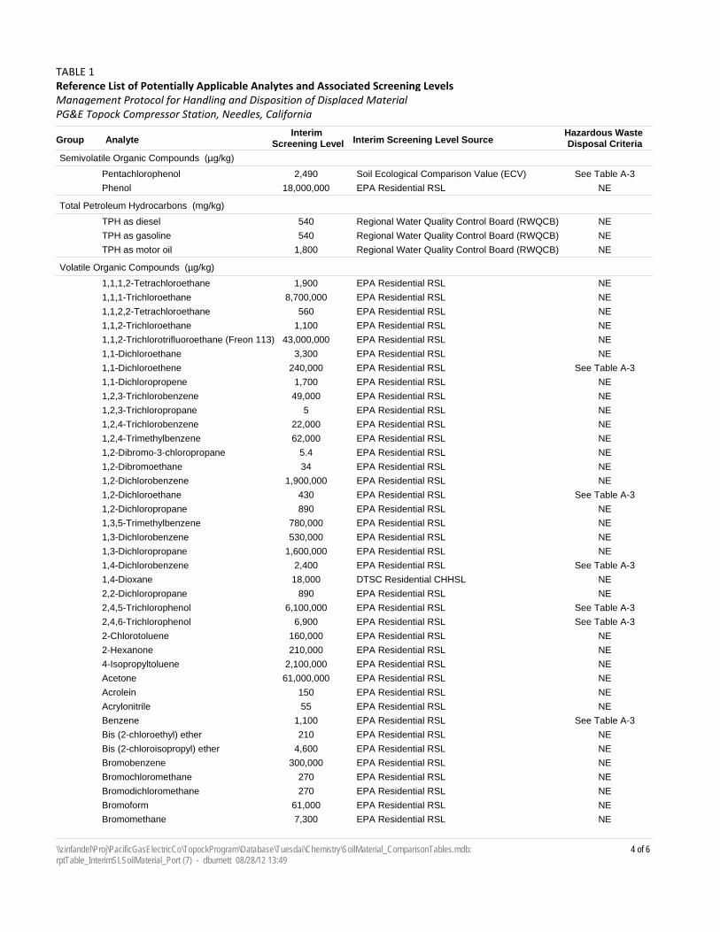
Interim Screening Level SourceInterim
Screening LevelAnalyteGroup
TABLE 1Reference List of Potentially Applicable Analytes and Associated Screening Levels
PG&E Topock Compressor Station, Needles, California
Hazardous Waste Disposal Criteria
Management Protocol for Handling and Disposition of Displaced Material
Semivolatile Organic Compounds (µg/kg)
Soil Ecological Comparison Value (ECV)2,490Pentachlorophenol See Table A-3
EPA Residential RSL18,000,000Phenol NE
Total Petroleum Hydrocarbons (mg/kg)
Regional Water Quality Control Board (RWQCB)540TPH as diesel NE
Regional Water Quality Control Board (RWQCB)540TPH as gasoline NE
Regional Water Quality Control Board (RWQCB)1,800TPH as motor oil NE
Volatile Organic Compounds (µg/kg)
EPA Residential RSL1,9001,1,1,2-Tetrachloroethane NE
EPA Residential RSL8,700,0001,1,1-Trichloroethane NE
EPA Residential RSL5601,1,2,2-Tetrachloroethane NE
EPA Residential RSL1,1001,1,2-Trichloroethane NE
EPA Residential RSL43,000,0001,1,2-Trichlorotrifluoroethane (Freon 113) NE
EPA Residential RSL3,3001,1-Dichloroethane NE
EPA Residential RSL240,0001,1-Dichloroethene See Table A-3
EPA Residential RSL1,7001,1-Dichloropropene NE
EPA Residential RSL49,0001,2,3-Trichlorobenzene NE
EPA Residential RSL51,2,3-Trichloropropane NE
EPA Residential RSL22,0001,2,4-Trichlorobenzene NE
EPA Residential RSL62,0001,2,4-Trimethylbenzene NE
EPA Residential RSL5.41,2-Dibromo-3-chloropropane NE
EPA Residential RSL341,2-Dibromoethane NE
EPA Residential RSL1,900,0001,2-Dichlorobenzene NE
EPA Residential RSL4301,2-Dichloroethane See Table A-3
EPA Residential RSL8901,2-Dichloropropane NE
EPA Residential RSL780,0001,3,5-Trimethylbenzene NE
EPA Residential RSL530,0001,3-Dichlorobenzene NE
EPA Residential RSL1,600,0001,3-Dichloropropane NE
EPA Residential RSL2,4001,4-Dichlorobenzene See Table A-3
DTSC Residential CHHSL18,0001,4-Dioxane NE
EPA Residential RSL8902,2-Dichloropropane NE
EPA Residential RSL6,100,0002,4,5-Trichlorophenol See Table A-3
EPA Residential RSL6,9002,4,6-Trichlorophenol See Table A-3
EPA Residential RSL160,0002-Chlorotoluene NE
EPA Residential RSL210,0002-Hexanone NE
EPA Residential RSL2,100,0004-Isopropyltoluene NE
EPA Residential RSL61,000,000Acetone NE
EPA Residential RSL150Acrolein NE
EPA Residential RSL55Acrylonitrile NE
EPA Residential RSL1,100Benzene See Table A-3
EPA Residential RSL210Bis (2-chloroethyl) ether NE
EPA Residential RSL4,600Bis (2-chloroisopropyl) ether NE
EPA Residential RSL300,000Bromobenzene NE
EPA Residential RSL270Bromochloromethane NE
EPA Residential RSL270Bromodichloromethane NE
EPA Residential RSL61,000Bromoform NE
EPA Residential RSL7,300Bromomethane NE
4 of 6\\zinfandel\Proj\PacificGasElectricCo\TopockProgram\Database\Tuesdai\Chemistry\SoilMaterial_ComparisonTables.mdb: rptTable_InterimSLSoilMaterial_Port (7) - dburnett 08/28/12 13:49
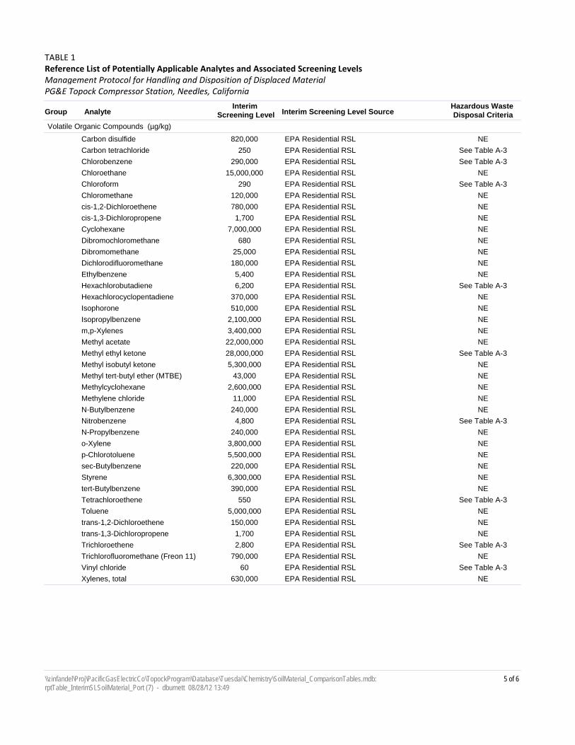
Interim Screening Level SourceInterim
Screening LevelAnalyteGroup
TABLE 1Reference List of Potentially Applicable Analytes and Associated Screening Levels
PG&E Topock Compressor Station, Needles, California
Hazardous Waste Disposal Criteria
Management Protocol for Handling and Disposition of Displaced Material
Volatile Organic Compounds (µg/kg)
EPA Residential RSL820,000Carbon disulfide NE
EPA Residential RSL250Carbon tetrachloride See Table A-3
EPA Residential RSL290,000Chlorobenzene See Table A-3
EPA Residential RSL15,000,000Chloroethane NE
EPA Residential RSL290Chloroform See Table A-3
EPA Residential RSL120,000Chloromethane NE
EPA Residential RSL780,000cis-1,2-Dichloroethene NE
EPA Residential RSL1,700cis-1,3-Dichloropropene NE
EPA Residential RSL7,000,000Cyclohexane NE
EPA Residential RSL680Dibromochloromethane NE
EPA Residential RSL25,000Dibromomethane NE
EPA Residential RSL180,000Dichlorodifluoromethane NE
EPA Residential RSL5,400Ethylbenzene NE
EPA Residential RSL6,200Hexachlorobutadiene See Table A-3
EPA Residential RSL370,000Hexachlorocyclopentadiene NE
EPA Residential RSL510,000Isophorone NE
EPA Residential RSL2,100,000Isopropylbenzene NE
EPA Residential RSL3,400,000m,p-Xylenes NE
EPA Residential RSL22,000,000Methyl acetate NE
EPA Residential RSL28,000,000Methyl ethyl ketone See Table A-3
EPA Residential RSL5,300,000Methyl isobutyl ketone NE
EPA Residential RSL43,000Methyl tert-butyl ether (MTBE) NE
EPA Residential RSL2,600,000Methylcyclohexane NE
EPA Residential RSL11,000Methylene chloride NE
EPA Residential RSL240,000N-Butylbenzene NE
EPA Residential RSL4,800Nitrobenzene See Table A-3
EPA Residential RSL240,000N-Propylbenzene NE
EPA Residential RSL3,800,000o-Xylene NE
EPA Residential RSL5,500,000p-Chlorotoluene NE
EPA Residential RSL220,000sec-Butylbenzene NE
EPA Residential RSL6,300,000Styrene NE
EPA Residential RSL390,000tert-Butylbenzene NE
EPA Residential RSL550Tetrachloroethene See Table A-3
EPA Residential RSL5,000,000Toluene NE
EPA Residential RSL150,000trans-1,2-Dichloroethene NE
EPA Residential RSL1,700trans-1,3-Dichloropropene NE
EPA Residential RSL2,800Trichloroethene See Table A-3
EPA Residential RSL790,000Trichlorofluoromethane (Freon 11) NE
EPA Residential RSL60Vinyl chloride See Table A-3
EPA Residential RSL630,000Xylenes, total NE
5 of 6\\zinfandel\Proj\PacificGasElectricCo\TopockProgram\Database\Tuesdai\Chemistry\SoilMaterial_ComparisonTables.mdb: rptTable_InterimSLSoilMaterial_Port (7) - dburnett 08/28/12 13:49
Notes:
California Department of Toxic Substances Control; California human health screening levels (OEHHA, 2005)
milligrams per kilogram
DTSC CHHSL
mg/kg
Interim screening level is background value. If background value is not available then the lesser of the DTSC residential CHHSL or the ecological comparison value is used. If CHHSL is not available, it is the lesser of the USEPA residential regional screening level or the ecological comparison value.
Background "Final Soil Background Investigation at Pacific Gas and Electric Company Topock Compressor Station, Needles, California" (CH2M HIll, May 2009)
United States Environmental Protection Agency Regional Screening Level, various dates. See Tables 3-1 to 3-8 of the Soil Investigation Part A Phase 1 Data Gaps Evaluation Report (CH2M HILL, 5/2011) for respective dates for each RSL.
EPA RSL
micrograms per kilogramµg/kg
Ecological Comparison Values; ECV were calculated as needed for constituents detected during the Part APhase I sampling (Arcadis, 2008)
ECV
"San Francisco Bay Regional Water Quality Control Board Environmental Screening Levels, Screening For Environmental Concerns at Sites With Contaminated Soil and Groundwater" (Table K-1). May 27, 2008
RWQCB
nanograms per kilogramng/kg
This table presents a reference list of analytes and associated screening levels that may be applicable for making decisions related to disposition of displaced site materials. The specific analytes and screening levels applicable for characterization of displaced material will be determined based on the origin of the material and potential disposition locations.
not establishedNE
One or more screening levels (EPA RSL, DTSC CHHSL, ECV, or Soil SL) have values lower than the background level.*
6 of 6\\zinfandel\Proj\PacificGasElectricCo\TopockProgram\Database\Tuesdai\Chemistry\SoilMaterial_ComparisonTables.mdb: rptTable_InterimSLSoilMaterial_Port (7) - dburnett 08/28/12 13:49
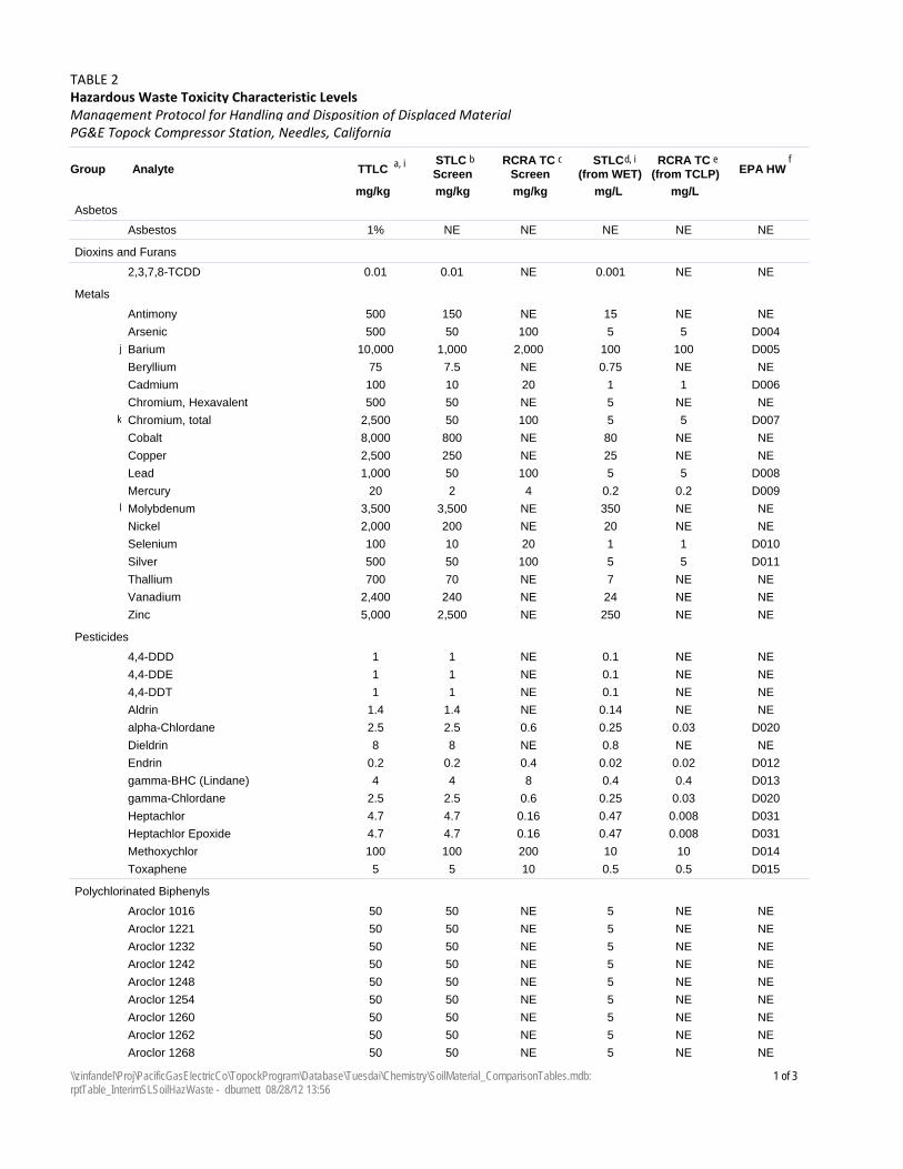
TTLCAnalyteGroupSTLC Screen
RCRA TC Screen
STLC (from WET)
RCRA TC (from TCLP)
mg/kg mg/kg mg/kg mg/L mg/L
a, i b d, ic eEPA HW
f
TABLE 2Hazardous Waste Toxicity Characteristic Levels
PG&E Topock Compressor Station, Needles, CaliforniaManagement Protocol for Handling and Disposition of Displaced Material
Asbetos
1%Asbestos NE NE NE NE NE
Dioxins and Furans
0.012,3,7,8-TCDD 0.01 NE 0.001 NE NE
Metals
500Antimony 150 NE 15 NE NE
500Arsenic 50 100 5 5 D004
10,000Barium 1,000 2,000 100 100j D005
75Beryllium 7.5 NE 0.75 NE NE
100Cadmium 10 20 1 1 D006
500Chromium, Hexavalent 50 NE 5 NE NE
2,500Chromium, total 50 100 5 5k D007
8,000Cobalt 800 NE 80 NE NE
2,500Copper 250 NE 25 NE NE
1,000Lead 50 100 5 5 D008
20Mercury 2 4 0.2 0.2 D009
3,500Molybdenum 3,500 NE 350 NEl NE
2,000Nickel 200 NE 20 NE NE
100Selenium 10 20 1 1 D010
500Silver 50 100 5 5 D011
700Thallium 70 NE 7 NE NE
2,400Vanadium 240 NE 24 NE NE
5,000Zinc 2,500 NE 250 NE NE
Pesticides
14,4-DDD 1 NE 0.1 NE NE
14,4-DDE 1 NE 0.1 NE NE
14,4-DDT 1 NE 0.1 NE NE
1.4Aldrin 1.4 NE 0.14 NE NE
2.5alpha-Chlordane 2.5 0.6 0.25 0.03 D020
8Dieldrin 8 NE 0.8 NE NE
0.2Endrin 0.2 0.4 0.02 0.02 D012
4gamma-BHC (Lindane) 4 8 0.4 0.4 D013
2.5gamma-Chlordane 2.5 0.6 0.25 0.03 D020
4.7Heptachlor 4.7 0.16 0.47 0.008 D031
4.7Heptachlor Epoxide 4.7 0.16 0.47 0.008 D031
100Methoxychlor 100 200 10 10 D014
5Toxaphene 5 10 0.5 0.5 D015
Polychlorinated Biphenyls
50Aroclor 1016 50 NE 5 NE NE
50Aroclor 1221 50 NE 5 NE NE
50Aroclor 1232 50 NE 5 NE NE
50Aroclor 1242 50 NE 5 NE NE
50Aroclor 1248 50 NE 5 NE NE
50Aroclor 1254 50 NE 5 NE NE
50Aroclor 1260 50 NE 5 NE NE
50Aroclor 1262 50 NE 5 NE NE
50Aroclor 1268 50 NE 5 NE NE
1 of 3\\zinfandel\Proj\PacificGasElectricCo\TopockProgram\Database\Tuesdai\Chemistry\SoilMaterial_ComparisonTables.mdb: rptTable_InterimSLSoilHazWaste - dburnett 08/28/12 13:56
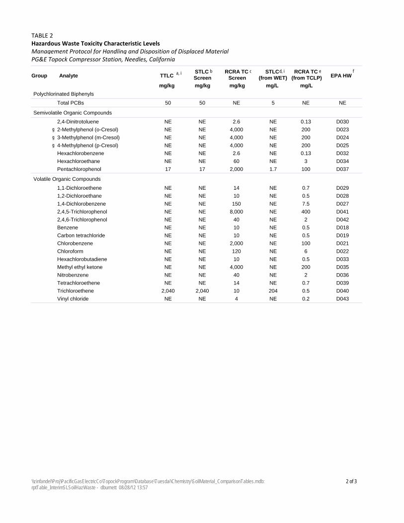
TTLCAnalyteGroupSTLC Screen
RCRA TC Screen
STLC (from WET)
RCRA TC (from TCLP)
mg/kg mg/kg mg/kg mg/L mg/L
a, i b d, ic eEPA HW
f
TABLE 2Hazardous Waste Toxicity Characteristic Levels
PG&E Topock Compressor Station, Needles, CaliforniaManagement Protocol for Handling and Disposition of Displaced Material
Polychlorinated Biphenyls
50Total PCBs 50 NE 5 NE NE
Semivolatile Organic Compounds
NE2,4-Dinitrotoluene NE 2.6 NE 0.13 D030
NE2-Methylphenol (o-Cresol) NE 4,000 NE 200g D023
NE3-Methylphenol (m-Cresol) NE 4,000 NE 200g D024
NE4-Methylphenol (p-Cresol) NE 4,000 NE 200g D025
NEHexachlorobenzene NE 2.6 NE 0.13 D032
NEHexachloroethane NE 60 NE 3 D034
17Pentachlorophenol 17 2,000 1.7 100 D037
Volatile Organic Compounds
NE1,1-Dichloroethene NE 14 NE 0.7 D029
NE1,2-Dichloroethane NE 10 NE 0.5 D028
NE1,4-Dichlorobenzene NE 150 NE 7.5 D027
NE2,4,5-Trichlorophenol NE 8,000 NE 400 D041
NE2,4,6-Trichlorophenol NE 40 NE 2 D042
NEBenzene NE 10 NE 0.5 D018
NECarbon tetrachloride NE 10 NE 0.5 D019
NEChlorobenzene NE 2,000 NE 100 D021
NEChloroform NE 120 NE 6 D022
NEHexachlorobutadiene NE 10 NE 0.5 D033
NEMethyl ethyl ketone NE 4,000 NE 200 D035
NENitrobenzene NE 40 NE 2 D036
NETetrachloroethene NE 14 NE 0.7 D039
2,040Trichloroethene 2,040 10 204 0.5 D040
NEVinyl chloride NE 4 NE 0.2 D043
2 of 3\\zinfandel\Proj\PacificGasElectricCo\TopockProgram\Database\Tuesdai\Chemistry\SoilMaterial_ComparisonTables.mdb: rptTable_InterimSLSoilHazWaste - dburnett 08/28/12 13:57
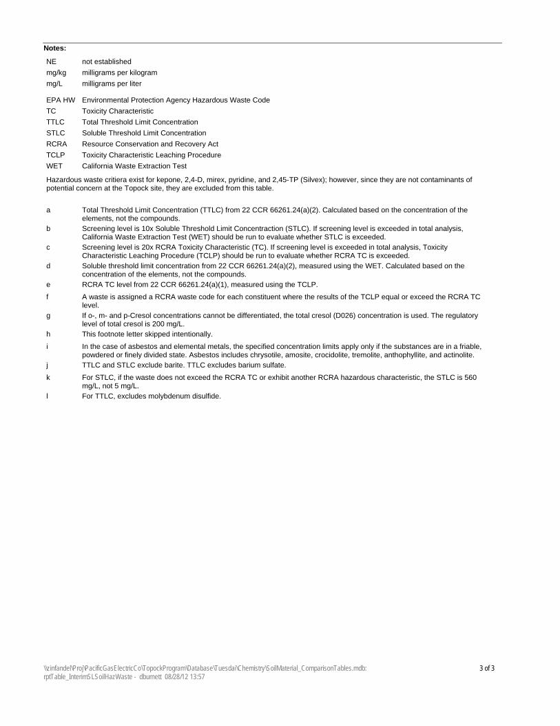
Notes:
milligrams per kilogrammg/kg
milligrams per litermg/L
not establishedNE
Total Threshold Limit ConcentrationTTLC
Soluble Threshold Limit ConcentrationSTLC
Toxicity Characteristic Leaching ProcedureTCLP
Resource Conservation and Recovery ActRCRA
Toxicity CharacteristicTC
California Waste Extraction TestWET
Environmental Protection Agency Hazardous Waste CodeEPA HW
Hazardous waste critiera exist for kepone, 2,4-D, mirex, pyridine, and 2,45-TP (Silvex); however, since they are not contaminants of potential concern at the Topock site, they are excluded from this table.
Total Threshold Limit Concentration (TTLC) from 22 CCR 66261.24(a)(2). Calculated based on the concentration of the elements, not the compounds.
a
Screening level is 10x Soluble Threshold Limit Concentraction (STLC). If screening level is exceeded in total analysis, California Waste Extraction Test (WET) should be run to evaluate whether STLC is exceeded.
b
Screening level is 20x RCRA Toxicity Characteristic (TC). If screening level is exceeded in total analysis, Toxicity Characteristic Leaching Procedure (TCLP) should be run to evaluate whether RCRA TC is exceeded.
c
Soluble threshold limit concentration from 22 CCR 66261.24(a)(2), measured using the WET. Calculated based on the concentration of the elements, not the compounds.
d
RCRA TC level from 22 CCR 66261.24(a)(1), measured using the TCLP.e
A waste is assigned a RCRA waste code for each constituent where the results of the TCLP equal or exceed the RCRA TC level.
f
If o-, m- and p-Cresol concentrations cannot be differentiated, the total cresol (D026) concentration is used. The regulatory level of total cresol is 200 mg/L.
g
This footnote letter skipped intentionally.h
In the case of asbestos and elemental metals, the specified concentration limits apply only if the substances are in a friable, powdered or finely divided state. Asbestos includes chrysotile, amosite, crocidolite, tremolite, anthophyllite, and actinolite.
i
TTLC and STLC exclude barite. TTLC excludes barium sulfate.j
For STLC, if the waste does not exceed the RCRA TC or exhibit another RCRA hazardous characteristic, the STLC is 560 mg/L, not 5 mg/L.
k
For TTLC, excludes molybdenum disulfide.l
3 of 3\\zinfandel\Proj\PacificGasElectricCo\TopockProgram\Database\Tuesdai\Chemistry\SoilMaterial_ComparisonTables.mdb: rptTable_InterimSLSoilHazWaste - dburnett 08/28/12 13:57

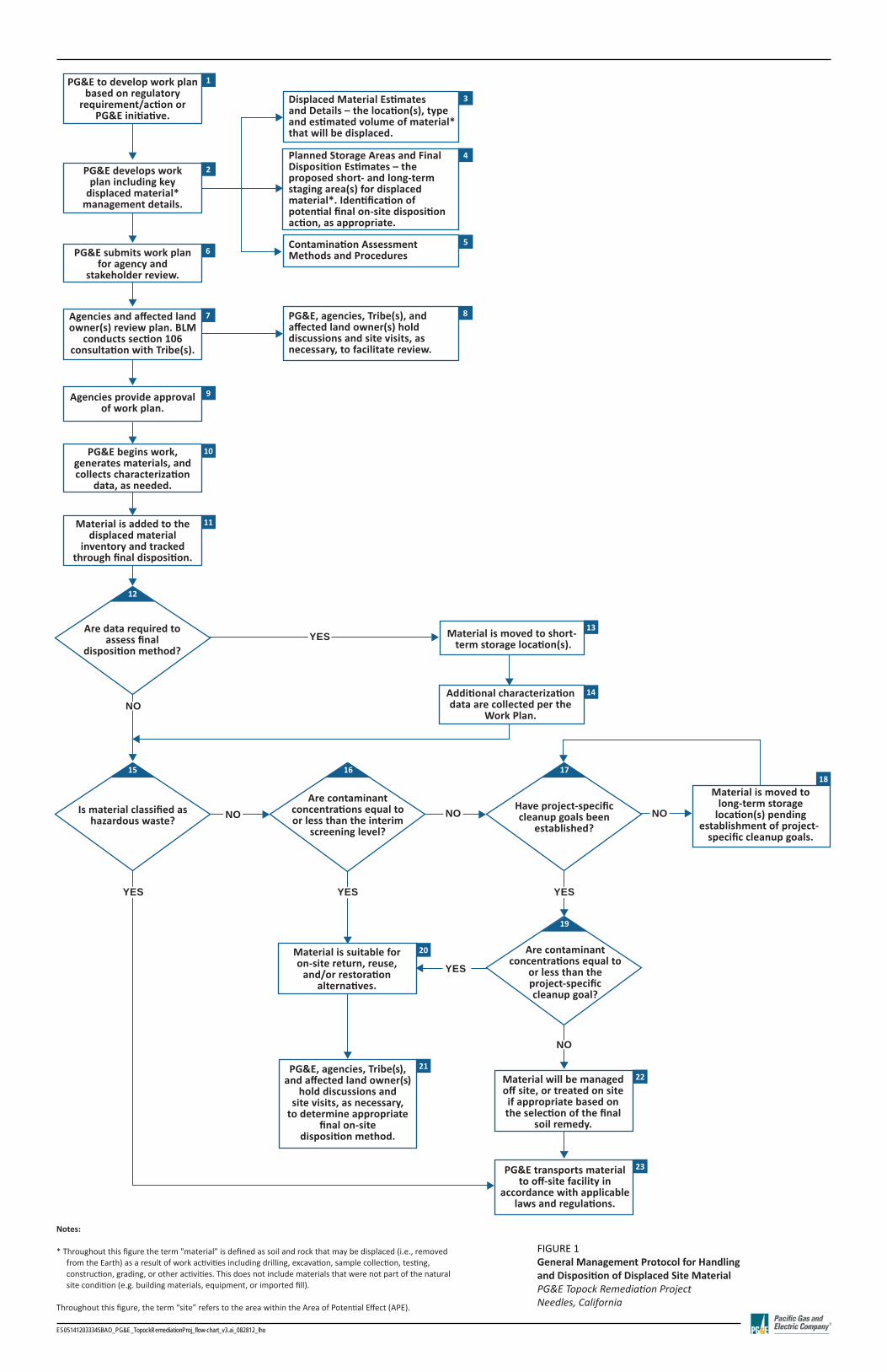
FIGURE 1General Management Protocol for Handling and Disposi on of Displaced Site MaterialPG&E Topock Remedia on ProjectNeedles, California
ES051412033345BAO_PG&E_TopockRemediationProj_flow-chart_v3.ai_082812_lho
1
2
3
4
56
7 8
9
10
11
13
14
20
2122
23
18
PG&E to develop work plan based on regulatory
requirement/action or PG&E initiative.
PG&E develops workplan including key
displaced material*management details.
PG&E submits work plan for agency and
stakeholder review.
Agencies and affected land owner(s) review plan. BLM
conducts section 106 consultation with Tribe(s).
Agencies provide approvalof work plan.
PG&E begins work, generates materials, and collects characterization
data, as needed.
Material is added to the displaced material
inventory and tracked through final disposition.
Are data required to assess final
disposition method?
Is material classified as hazardous waste?
PG&E, agencies, Tribe(s), and affected land owner(s)
hold discussions andsite visits, as necessary,
to determine appropriate final on-site
disposition method.
Material is suitable for on-site return, reuse,
and/or restorationalternatives.
PG&E transports materialto off-site facility in
accordance with applicable laws and regulations.
Material will be managed off site, or treated on site if appropriate based on the selection of the final
soil remedy.
Are contaminant concentrations equal to or less than the interim
screening level?
Have project-specific cleanup goals been
established?
Are contaminant concentrations equal to
or less than the project-specificcleanup goal?
Additional characterization data are collected per the
Work Plan.
Material is moved to long-term storage
location(s) pending establishment of project-
specific cleanup goals.
Material is moved to short-term storage location(s).
PG&E, agencies, Tribe(s), and affected land owner(s) hold discussions and site visits, as necessary, to facilitate review.
Contamination Assessment Methods and Procedures
Planned Storage Areas and Final Disposition Estimates – the proposed short- and long-term staging area(s) for displaced material*. Identification of potential final on-site disposition action, as appropriate.
Displaced Material Estimatesand Details – the location(s), type and estimated volume of material*that will be displaced.
NO
YES
NO NO
YES
YES
NO
NO
YES YES
12
15 16 17
19
Notes:
* Throughout this figure the term "material" is defined as soil and rock that may be displaced (i.e., removed from the Earth) as a result of work activities including drilling, excavation, sample collection, testing, construction, grading, or other activities. This does not include materials that were not part of the natural site condition (e.g. building materials, equipment, or imported fill).
Throughout this figure, the term “site” refers to the area within the Area of Potential Effect (APE).

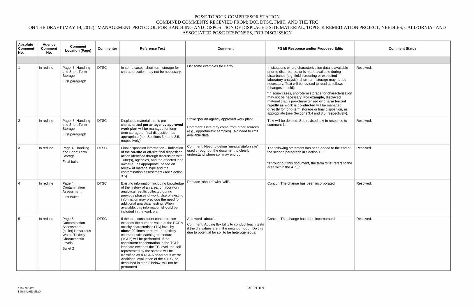
PG&E TOPOCK COMPRESSOR STATION COMBINED COMMENTS RECEVIED FROM: DOI, DTSC, FMIT, AND THE TRC
ON THE DRAFT (MAY 14, 2012) “MANAGEMENT PROTOCOL FOR HANDLING AND DISPOSITION OF DISPLACED SITE MATERIAL, TOPOCK REMEDIATION PROJECT, NEEDLES, CALIFORNIA” AND ASSOCIATED PG&E RESPONSES, FOR DISCUSSION
SFO\122410002 PAGE 1 OF 9 ES051412033345BAO
Absolute Comment No.
Agency Comment
No.
Comment Location (Page)
Commenter Reference Text Comment PG&E Response and/or Proposed Edits Comment Status
1 In redline Page 3, Handling and Short Term Storage
First paragraph
DTSC In some cases, short-term storage for characterization may not be necessary.
List some examples for clarity.
In situations where characterization data is available prior to disturbance, or is made available during disturbance (e.g. field screening or expedited laboratory analysis), short-term storage may not be necessary. Text will be revised to read as follows (changes in bold):
“In some cases, short-term storage for characterization may not be necessary. For example, displaced material that is pre-characterized or characterized rapidly as work is conducted will be managed directly for long-term storage or final disposition, as appropriate (see Sections 3.4 and 3.5, respectively).
Resolved.
2 In redline Page 3, Handling and Short Term Storage
First paragraph
DTSC Displaced material that is pre-characterized per an agency approved work plan will be managed for long-term storage or final disposition, as appropriate (see Sections 3.4 and 3.5, respectively)
Strike “per an agency approved work plan”. Comment: Data may come from other sources (e.g., opportunistic samples). No need to limit available data.
Text will be deleted. See revised text in response to comment 1.
Resolved.
3 In redline Page 4, Handling and Short Term Storage
Final bullet
DTSC Final disposition information – Indication of the on-site or off-site final disposition action identified through discussion with Tribe(s), agencies, and the affected land owner(s), as appropriate, based on review of material type and the contamination assessment (see Section 3.5).
Comment: Need to define “on-site/site/on site” used throughout the document to clearly understand where soil may end up.
The following statement has been added to the end of the second paragraph in Section 1.0:
“Throughout this document, the term “site” refers to the area within the APE.”
Resolved.
4 In redline Page 4, Contamination Assessment
First bullet
DTSC Existing information including knowledge of the history of an area, or laboratory analytical results collected during previous phases of work. Use of existing information may preclude the need for additional analytical testing. When available, this information should be included in the work plan.
Replace “should” with “will”.
Concur. The change has been incorporated. Resolved.
5 In redline Page 5, Contamination Assessment – (bullet) Hazardous Waste Toxicity Characteristic Levels
Bullet 2
DTSC If the total constituent concentration exceeds the numeric value of the RCRA toxicity characteristic (TC) level by about 20 times or more, the toxicity characteristic leaching procedure (TCLP) will be performed. If the constituent concentration in the TCLP leachate exceeds the TC level, the soil represented by the sample will be classified as a RCRA hazardous waste. Additional evaluation of the STLC, as described in step 3 below, will not be performed.
Add word “about”.
Comment: Adding flexibility to conduct leach tests if the dry values are in the neighborhood. Do this due to potential for soil to be heterogeneous.
Concur. The change has been incorporated.
Resolved.
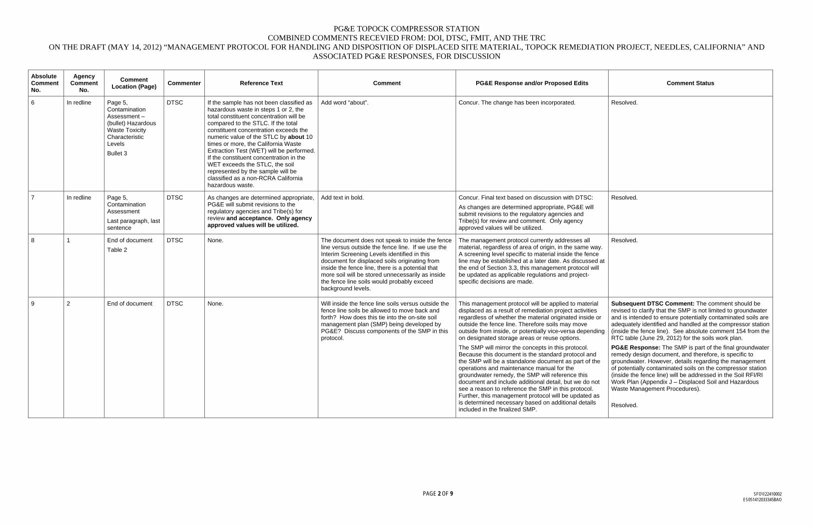
PG&E TOPOCK COMPRESSOR STATION COMBINED COMMENTS RECEVIED FROM: DOI, DTSC, FMIT, AND THE TRC
ON THE DRAFT (MAY 14, 2012) “MANAGEMENT PROTOCOL FOR HANDLING AND DISPOSITION OF DISPLACED SITE MATERIAL, TOPOCK REMEDIATION PROJECT, NEEDLES, CALIFORNIA” AND ASSOCIATED PG&E RESPONSES, FOR DISCUSSION
PAGE 2 OF 9 SFO\122410002 ES051412033345BAO
Absolute Comment No.
Agency Comment
No.
Comment Location (Page)
Commenter Reference Text Comment PG&E Response and/or Proposed Edits Comment Status
6 In redline Page 5, Contamination Assessment – (bullet) Hazardous Waste Toxicity Characteristic Levels
Bullet 3
DTSC If the sample has not been classified as hazardous waste in steps 1 or 2, the total constituent concentration will be compared to the STLC. If the total constituent concentration exceeds the numeric value of the STLC by about 10 times or more, the California Waste Extraction Test (WET) will be performed. If the constituent concentration in the WET exceeds the STLC, the soil represented by the sample will be classified as a non-RCRA California hazardous waste.
Add word “about”.
Concur. The change has been incorporated. Resolved.
7 In redline Page 5, Contamination Assessment
Last paragraph, last sentence
DTSC As changes are determined appropriate, PG&E will submit revisions to the regulatory agencies and Tribe(s) for review and acceptance. Only agency approved values will be utilized.
Add text in bold.
Concur. Final text based on discussion with DTSC:
As changes are determined appropriate, PG&E will submit revisions to the regulatory agencies and Tribe(s) for review and comment. Only agency approved values will be utilized.
Resolved.
8 1 End of document
Table 2
DTSC None. The document does not speak to inside the fence line versus outside the fence line. If we use the Interim Screening Levels identified in this document for displaced soils originating from inside the fence line, there is a potential that more soil will be stored unnecessarily as inside the fence line soils would probably exceed background levels.
The management protocol currently addresses all material, regardless of area of origin, in the same way. A screening level specific to material inside the fence line may be established at a later date. As discussed at the end of Section 3.3, this management protocol will be updated as applicable regulations and project-specific decisions are made.
Resolved.
9 2 End of document DTSC None. Will inside the fence line soils versus outside the fence line soils be allowed to move back and forth? How does this tie into the on-site soil management plan (SMP) being developed by PG&E? Discuss components of the SMP in this protocol.
This management protocol will be applied to material displaced as a result of remediation project activities regardless of whether the material originated inside or outside the fence line. Therefore soils may move outside from inside, or potentially vice-versa depending on designated storage areas or reuse options.
The SMP will mirror the concepts in this protocol. Because this document is the standard protocol and the SMP will be a standalone document as part of the operations and maintenance manual for the groundwater remedy, the SMP will reference this document and include additional detail, but we do not see a reason to reference the SMP in this protocol. Further, this management protocol will be updated as is determined necessary based on additional details included in the finalized SMP.
Subsequent DTSC Comment: The comment should be revised to clarify that the SMP is not limited to groundwater and is intended to ensure potentially contaminated soils are adequately identified and handled at the compressor station (inside the fence line). See absolute comment 154 from the RTC table (June 29, 2012) for the soils work plan.
PG&E Response: The SMP is part of the final groundwater remedy design document, and therefore, is specific to groundwater. However, details regarding the management of potentially contaminated soils on the compressor station (inside the fence line) will be addressed in the Soil RFI/RI Work Plan (Appendix J – Displaced Soil and Hazardous Waste Management Procedures).
Resolved.
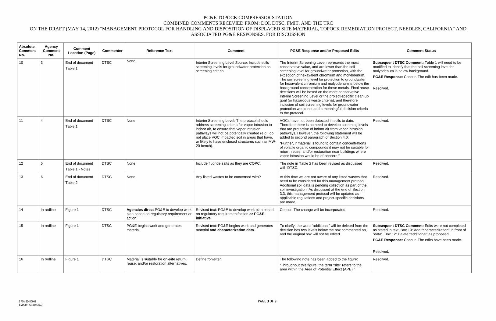
PG&E TOPOCK COMPRESSOR STATION COMBINED COMMENTS RECEVIED FROM: DOI, DTSC, FMIT, AND THE TRC
ON THE DRAFT (MAY 14, 2012) “MANAGEMENT PROTOCOL FOR HANDLING AND DISPOSITION OF DISPLACED SITE MATERIAL, TOPOCK REMEDIATION PROJECT, NEEDLES, CALIFORNIA” AND ASSOCIATED PG&E RESPONSES, FOR DISCUSSION
SFO\122410002 PAGE 3 OF 9 ES051412033345BAO
Absolute Comment No.
Agency Comment
No.
Comment Location (Page)
Commenter Reference Text Comment PG&E Response and/or Proposed Edits Comment Status
10 3 End of document
Table 1
DTSC None. Interim Screening Level Source: Include soils screening levels for groundwater protection as screening criteria.
The Interim Screening Level represents the most conservative value, and are lower than the soil screening level for groundwater protection, with the exception of hexavalent chromium and molybdenum. The soil screening level for protection to groundwater for hexavalent chromium and molybdenum is below the background concentration for these metals. Final reuse decisions will be based on the more conservative Interim Screening Level or the project-specific clean up goal (or hazardous waste criteria), and therefore inclusion of soil screening levels for groundwater protection would not add a meaningful decision criteria to the protocol.
Subsequent DTSC Comment: Table 1 will need to be modified to identify that the soil screening level for molybdenum is below background.
PG&E Response: Concur. The edit has been made.
Resolved.
11 4 End of document
Table 1
DTSC None. Interim Screening Level: The protocol should address screening criteria for vapor intrusion to indoor air, to ensure that vapor intrusion pathways will not be potentially created (e.g., do not place VOC impacted soil in areas that have, or likely to have enclosed structures such as MW-20 bench).
VOCs have not been detected in soils to date. Therefore there is no need to develop screening levels that are protective of indoor air from vapor intrusion pathways. However, the following statement will be added to second paragraph of Section 4.0:
“Further, if material is found to contain concentrations of volatile organic compounds it may not be suitable for return, reuse, and/or restoration near buildings where vapor intrusion would be of concern.”
Resolved.
12 5 End of document
Table 1 - Notes
DTSC None. Include fluoride salts as they are COPC. The note in Table 2 has been revised as discussed with DTSC.
Resolved.
13 6 End of document
Table 2
DTSC None. Any listed wastes to be concerned with? At this time we are not aware of any listed wastes that need to be considered for this management protocol. Additional soil data is pending collection as part of the soil investigation. As discussed at the end of Section 3.3, this management protocol will be updated as applicable regulations and project-specific decisions are made.
Resolved.
14 In redline Figure 1 DTSC Agencies direct PG&E to develop work plan based on regulatory requirement or action.
Revised text: PG&E to develop work plan based on regulatory requirement/action or PG&E initiative.
Concur. The change will be incorporated. Resolved.
15 In redline Figure 1 DTSC PG&E begins work and generates material.
Revised text: PG&E begins work and generates material and characterization data.
To clarify, the word “additional” will be deleted from the decision box two levels below the box commented on, and the original box will not be edited.
Subsequent DTSC Comment: Edits were not completed as stated in text. Box 10: Add “characterization” in front of “data”. Box 12: Delete “additional” as proposed.
PG&E Response: Concur. The edits have been made.
Resolved.
16 In redline Figure 1 DTSC Material is suitable for on-site return, reuse, and/or restoration alternatives.
Define “on-site”. The following note has been added to the figure:
“Throughout this figure, the term “site” refers to the area within the Area of Potential Effect (APE).”
Resolved.
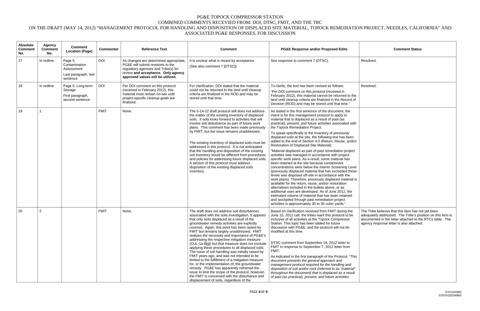
PG&E TOPOCK COMPRESSOR STATION COMBINED COMMENTS RECEVIED FROM: DOI, DTSC, FMIT, AND THE TRC
ON THE DRAFT (MAY 14, 2012) “MANAGEMENT PROTOCOL FOR HANDLING AND DISPOSITION OF DISPLACED SITE MATERIAL, TOPOCK REMEDIATION PROJECT, NEEDLES, CALIFORNIA” AND ASSOCIATED PG&E RESPONSES, FOR DISCUSSION
PAGE 4 OF 9 SFO\122410002 ES051412033345BAO
Absolute Comment No.
Agency Comment
No.
Comment Location (Page)
Commenter Reference Text Comment PG&E Response and/or Proposed Edits Comment Status
17 In redline Page 5, Contamination Assessment
Last paragraph, last sentence
DOI As changes are determined appropriate, PG&E will submit revisions to the regulatory agencies and Tribe(s) for review and acceptance. Only agency approved values will be utilized.
It is unclear what is meant by acceptance.
(See also comment 7 [DTSC])
See response to comment 7 (DTSC). Resolved.
18 In redline Page 6, Long-term Storage
First paragraph, second sentence
DOI Per DOI comment on this protocol (received in February 2012), this material must remain on-site until project-specific cleanup goals are finalized.
For clarification, DOI stated that the material could not be returned to the land until cleanup criteria are finalized in the ROD and may be stored until that time.
To clarify, the text has been revised as follows:
“Per DOI comment on this protocol (received in February 2012), this material cannot be returned to the land until cleanup criteria are finalized in the Record of Decision (ROD) and may be stored until that time.”
Resolved.
19 1 FMIT None. The 5-14-12 draft protocol still does not address the matter of the existing inventory of displaced soils. It only looks forward to activities that will involve soil disturbance as part of future work plans. This comment has been made previously by FMIT, but the issue remains unaddressed.
The existing inventory of displaced soils must be addressed in this protocol. It is not anticipated that the handling and disposition of the existing soil inventory would be different from procedures and policies for addressing future displaced soils. A section of this protocol must address disposition of the existing displaced soils inventory.
As stated in the first sentence of the document, the intent is for this management protocol to apply to material that is displaced as a result of past (as practical), present, and future activities associated with the Topock Remediation Project.
To speak specifically to the inventory of previously displaced soils at the site, the following text has been added to the end of Section 4.0 (Return, Reuse, and/or Restoration of Displaced Site Material):
“Material displaced as part of past remediation project activities was managed in accordance with project-specific work plans. As a result, some material has been retained at the site because contaminant concentrations were below the Interim Screening Level (previously displaced material that has exceeded these levels was disposed off-site in accordance with the work plans). Therefore, previously displaced material is available for the return, reuse, and/or restoration alternatives included in the bullets above, or as additional uses are developed. As of June 2012, the estimated volume of material that has been retained and stockpiled through past remediation project activities is approximately 30 to 35 cubic yards.”
20 2 FMIT None. The draft does not address soil disturbances associated with the soils investigation. It appears that only soils displaced as a result of the groundwater remedy activities are explicitly covered. Again, this point has been raised by FMIT but remains largely unaddressed. FMIT realizes the necessity and importance of PG&E’s addressing the respective mitigation measure (CUL-1a-8[g]) but that measure does not exclude applying these procedures to all displaced soils. The issue of soil handling was initially raised by FMIT years ago, and was not intended to be limited to the fulfillment of a mitigation measure for, or the implementation of, the groundwater remedy. PG&E has apparently reframed the issue to limit the scope of the protocol, however, the FMIT is concerned with the disturbance and displacement of soils, regardless of the
Based on clarification received from FMIT during the June 15, 2012 call, the tribes want this protocol to be inclusive of all activities at the Topock Compressor Station. This topic has been tabled for future discussion with PG&E, and the protocol will not be modified at this time.
DTSC comment from September 18, 2012 letter to FMIT in response to September 7, 2012 letter from FMIT:
As indicated in the first paragraph of the Protocol, “This document presents the general approach and management protocol required for the handling and disposition of soil and/or rock (referred to as “material” throughout the document) that is displaced as a result of past (as practical), present, and future activities
The Tribe believes that this item has not yet been adequately addressed. The Tribe’s position on this item is documented in the letter attached to the RTCs table. The agency response letter is also attached.
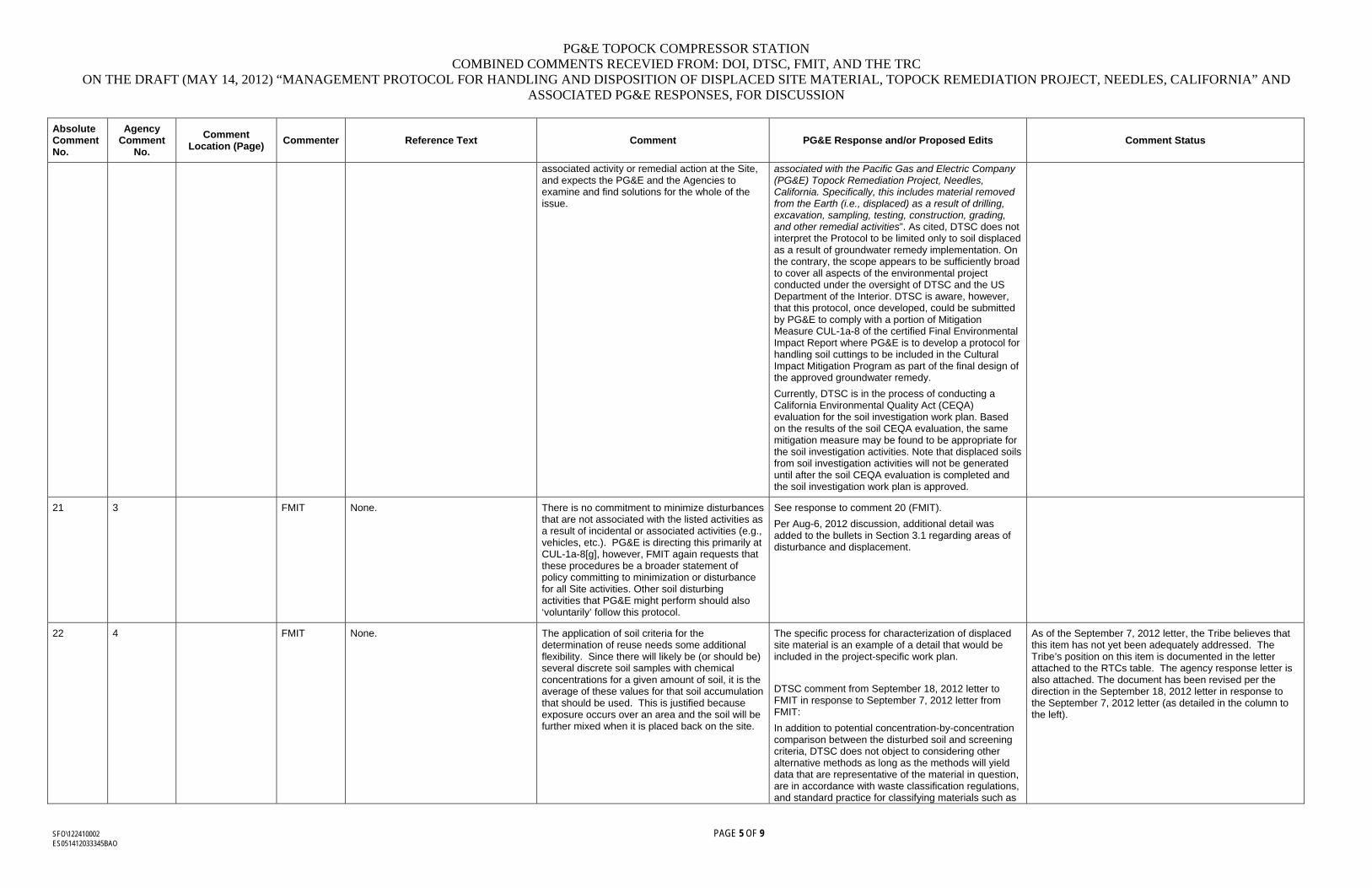
PG&E TOPOCK COMPRESSOR STATION COMBINED COMMENTS RECEVIED FROM: DOI, DTSC, FMIT, AND THE TRC
ON THE DRAFT (MAY 14, 2012) “MANAGEMENT PROTOCOL FOR HANDLING AND DISPOSITION OF DISPLACED SITE MATERIAL, TOPOCK REMEDIATION PROJECT, NEEDLES, CALIFORNIA” AND ASSOCIATED PG&E RESPONSES, FOR DISCUSSION
SFO\122410002 PAGE 5 OF 9 ES051412033345BAO
Absolute Comment No.
Agency Comment
No.
Comment Location (Page)
Commenter Reference Text Comment PG&E Response and/or Proposed Edits Comment Status
associated activity or remedial action at the Site, and expects the PG&E and the Agencies to examine and find solutions for the whole of the issue.
associated with the Pacific Gas and Electric Company (PG&E) Topock Remediation Project, Needles, California. Specifically, this includes material removed from the Earth (i.e., displaced) as a result of drilling, excavation, sampling, testing, construction, grading, and other remedial activities”. As cited, DTSC does not interpret the Protocol to be limited only to soil displaced as a result of groundwater remedy implementation. On the contrary, the scope appears to be sufficiently broad to cover all aspects of the environmental project conducted under the oversight of DTSC and the US Department of the Interior. DTSC is aware, however, that this protocol, once developed, could be submitted by PG&E to comply with a portion of Mitigation Measure CUL-1a-8 of the certified Final Environmental Impact Report where PG&E is to develop a protocol for handling soil cuttings to be included in the Cultural Impact Mitigation Program as part of the final design of the approved groundwater remedy.
Currently, DTSC is in the process of conducting a California Environmental Quality Act (CEQA) evaluation for the soil investigation work plan. Based on the results of the soil CEQA evaluation, the same mitigation measure may be found to be appropriate for the soil investigation activities. Note that displaced soils from soil investigation activities will not be generated until after the soil CEQA evaluation is completed and the soil investigation work plan is approved.
21 3 FMIT None. There is no commitment to minimize disturbances that are not associated with the listed activities as a result of incidental or associated activities (e.g., vehicles, etc.). PG&E is directing this primarily at CUL-1a-8[g], however, FMIT again requests that these procedures be a broader statement of policy committing to minimization or disturbance for all Site activities. Other soil disturbing activities that PG&E might perform should also ‘voluntarily’ follow this protocol.
See response to comment 20 (FMIT).
Per Aug-6, 2012 discussion, additional detail was added to the bullets in Section 3.1 regarding areas of disturbance and displacement.
22 4 FMIT None. The application of soil criteria for the determination of reuse needs some additional flexibility. Since there will likely be (or should be) several discrete soil samples with chemical concentrations for a given amount of soil, it is the average of these values for that soil accumulation that should be used. This is justified because exposure occurs over an area and the soil will be further mixed when it is placed back on the site.
The specific process for characterization of displaced site material is an example of a detail that would be included in the project-specific work plan.
DTSC comment from September 18, 2012 letter to FMIT in response to September 7, 2012 letter from FMIT:
In addition to potential concentration-by-concentration comparison between the disturbed soil and screening criteria, DTSC does not object to considering other alternative methods as long as the methods will yield data that are representative of the material in question, are in accordance with waste classification regulations, and standard practice for classifying materials such as
As of the September 7, 2012 letter, the Tribe believes that this item has not yet been adequately addressed. The Tribe’s position on this item is documented in the letter attached to the RTCs table. The agency response letter is also attached. The document has been revised per the direction in the September 18, 2012 letter in response to the September 7, 2012 letter (as detailed in the column to the left).
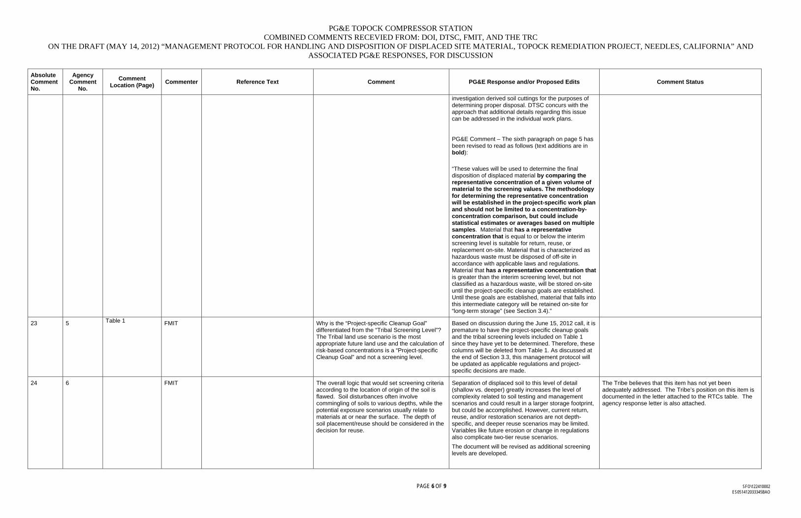
PG&E TOPOCK COMPRESSOR STATION COMBINED COMMENTS RECEVIED FROM: DOI, DTSC, FMIT, AND THE TRC
ON THE DRAFT (MAY 14, 2012) “MANAGEMENT PROTOCOL FOR HANDLING AND DISPOSITION OF DISPLACED SITE MATERIAL, TOPOCK REMEDIATION PROJECT, NEEDLES, CALIFORNIA” AND ASSOCIATED PG&E RESPONSES, FOR DISCUSSION
PAGE 6 OF 9 SFO\122410002 ES051412033345BAO
Absolute Comment No.
Agency Comment
No.
Comment Location (Page)
Commenter Reference Text Comment PG&E Response and/or Proposed Edits Comment Status
investigation derived soil cuttings for the purposes of determining proper disposal. DTSC concurs with the approach that additional details regarding this issue can be addressed in the individual work plans. PG&E Comment – The sixth paragraph on page 5 has been revised to read as follows (text additions are in bold):
“These values will be used to determine the final disposition of displaced material by comparing the representative concentration of a given volume of material to the screening values. The methodology for determining the representative concentration will be established in the project-specific work plan and should not be limited to a concentration-by-concentration comparison, but could include statistical estimates or averages based on multiple samples. Material that has a representative concentration that is equal to or below the interim screening level is suitable for return, reuse, or replacement on-site. Material that is characterized as hazardous waste must be disposed of off-site in accordance with applicable laws and regulations. Material that has a representative concentration that is greater than the interim screening level, but not classified as a hazardous waste, will be stored on-site until the project-specific cleanup goals are established. Until these goals are established, material that falls into this intermediate category will be retained on-site for “long-term storage” (see Section 3.4).”
23 5 Table 1 FMIT Why is the “Project-specific Cleanup Goal” differentiated from the “Tribal Screening Level”? The Tribal land use scenario is the most appropriate future land use and the calculation of risk-based concentrations is a “Project-specific Cleanup Goal” and not a screening level.
Based on discussion during the June 15, 2012 call, it is premature to have the project-specific cleanup goals and the tribal screening levels included on Table 1 since they have yet to be determined. Therefore, these columns will be deleted from Table 1. As discussed at the end of Section 3.3, this management protocol will be updated as applicable regulations and project-specific decisions are made.
24 6 FMIT The overall logic that would set screening criteria according to the location of origin of the soil is flawed. Soil disturbances often involve commingling of soils to various depths, while the potential exposure scenarios usually relate to materials at or near the surface. The depth of soil placement/reuse should be considered in the decision for reuse.
Separation of displaced soil to this level of detail (shallow vs. deeper) greatly increases the level of complexity related to soil testing and management scenarios and could result in a larger storage footprint, but could be accomplished. However, current return, reuse, and/or restoration scenarios are not depth-specific, and deeper reuse scenarios may be limited. Variables like future erosion or change in regulations also complicate two-tier reuse scenarios.
The document will be revised as additional screening levels are developed.
The Tribe believes that this item has not yet been adequately addressed. The Tribe’s position on this item is documented in the letter attached to the RTCs table. The agency response letter is also attached.
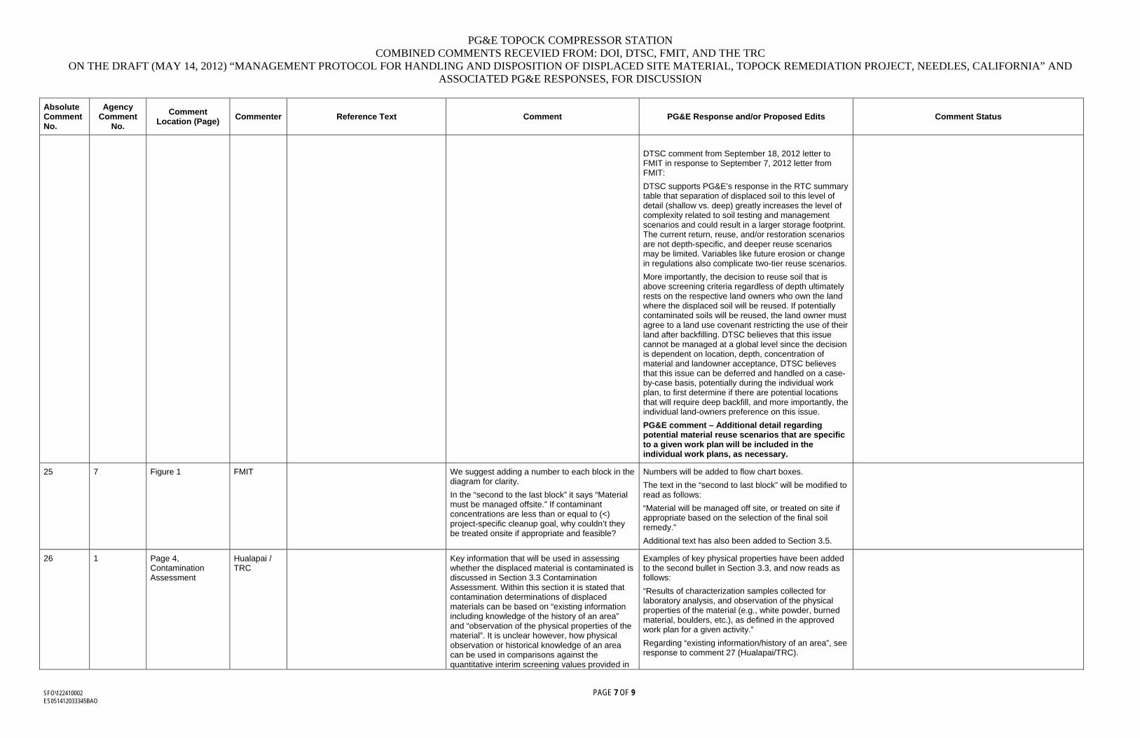
PG&E TOPOCK COMPRESSOR STATION COMBINED COMMENTS RECEVIED FROM: DOI, DTSC, FMIT, AND THE TRC
ON THE DRAFT (MAY 14, 2012) “MANAGEMENT PROTOCOL FOR HANDLING AND DISPOSITION OF DISPLACED SITE MATERIAL, TOPOCK REMEDIATION PROJECT, NEEDLES, CALIFORNIA” AND ASSOCIATED PG&E RESPONSES, FOR DISCUSSION
SFO\122410002 PAGE 7 OF 9 ES051412033345BAO
Absolute Comment No.
Agency Comment
No.
Comment Location (Page)
Commenter Reference Text Comment PG&E Response and/or Proposed Edits Comment Status
DTSC comment from September 18, 2012 letter to FMIT in response to September 7, 2012 letter from FMIT:
DTSC supports PG&E’s response in the RTC summary table that separation of displaced soil to this level of detail (shallow vs. deep) greatly increases the level of complexity related to soil testing and management scenarios and could result in a larger storage footprint. The current return, reuse, and/or restoration scenarios are not depth-specific, and deeper reuse scenarios may be limited. Variables like future erosion or change in regulations also complicate two-tier reuse scenarios.
More importantly, the decision to reuse soil that is above screening criteria regardless of depth ultimately rests on the respective land owners who own the land where the displaced soil will be reused. If potentially contaminated soils will be reused, the land owner must agree to a land use covenant restricting the use of their land after backfilling. DTSC believes that this issue cannot be managed at a global level since the decision is dependent on location, depth, concentration of material and landowner acceptance, DTSC believes that this issue can be deferred and handled on a case-by-case basis, potentially during the individual work plan, to first determine if there are potential locations that will require deep backfill, and more importantly, the individual land-owners preference on this issue.
PG&E comment – Additional detail regarding potential material reuse scenarios that are specific to a given work plan will be included in the individual work plans, as necessary.
25 7 Figure 1 FMIT We suggest adding a number to each block in the diagram for clarity.
In the “second to the last block” it says “Material must be managed offsite.” If contaminant concentrations are less than or equal to (<) project-specific cleanup goal, why couldn’t they be treated onsite if appropriate and feasible?
Numbers will be added to flow chart boxes.
The text in the “second to last block” will be modified to read as follows:
“Material will be managed off site, or treated on site if appropriate based on the selection of the final soil remedy.”
Additional text has also been added to Section 3.5.
26 1 Page 4, Contamination Assessment
Hualapai / TRC
Key information that will be used in assessing whether the displaced material is contaminated is discussed in Section 3.3 Contamination Assessment. Within this section it is stated that contamination determinations of displaced materials can be based on “existing information including knowledge of the history of an area” and “observation of the physical properties of the material”. It is unclear however, how physical observation or historical knowledge of an area can be used in comparisons against the quantitative interim screening values provided in
Examples of key physical properties have been added to the second bullet in Section 3.3, and now reads as follows:
“Results of characterization samples collected for laboratory analysis, and observation of the physical properties of the material (e.g., white powder, burned material, boulders, etc.), as defined in the approved work plan for a given activity.”
Regarding “existing information/history of an area”, see response to comment 27 (Hualapai/TRC).
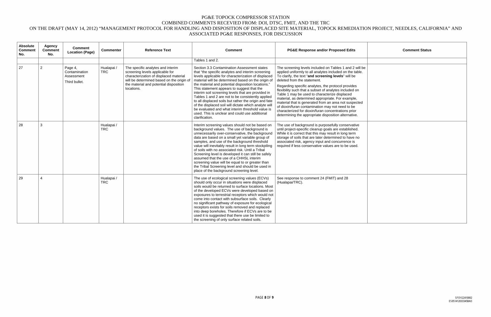
PG&E TOPOCK COMPRESSOR STATION COMBINED COMMENTS RECEVIED FROM: DOI, DTSC, FMIT, AND THE TRC
ON THE DRAFT (MAY 14, 2012) “MANAGEMENT PROTOCOL FOR HANDLING AND DISPOSITION OF DISPLACED SITE MATERIAL, TOPOCK REMEDIATION PROJECT, NEEDLES, CALIFORNIA” AND ASSOCIATED PG&E RESPONSES, FOR DISCUSSION
PAGE 8 OF 9 SFO\122410002 ES051412033345BAO
Absolute Comment No.
Agency Comment
No.
Comment Location (Page)
Commenter Reference Text Comment PG&E Response and/or Proposed Edits Comment Status
Tables 1 and 2.
27 2 Page 4, Contamination Assessment
Third bullet.
Hualapai / TRC
The specific analytes and interim screening levels applicable for characterization of displaced material will be determined based on the origin of the material and potential disposition locations.
Section 3.3 Contamination Assessment states that “the specific analytes and interim screening levels applicable for characterization of displaced material will be determined based on the origin of the material and potential disposition locations.” This statement appears to suggest that the interim soil screening levels that are provided in Tables 1 and 2 are not to be consistently applied to all displaced soils but rather the origin and fate of the displaced soil will dictate which analyte will be evaluated and what interim threshold value is used. This is unclear and could use additional clarification.
The screening levels included on Tables 1 and 2 will be applied uniformly to all analytes included on the table. To clarify, the text “and screening levels” will be deleted from the statement.
Regarding specific analytes, the protocol provides flexibility such that a subset of analytes included on Table 1 may be used to characterize displaced material, as determined appropriate. For example, material that is generated from an area not suspected of dioxin/furan contamination may not need to be characterized for dioxin/furan concentrations prior determining the appropriate disposition alternative.
28 3 Hualapai / TRC
Interim screening values should not be based on background values. The use of background is unnecessarily over-conservative, the background data are based on a small yet variable group of samples, and use of the background threshold value will inevitably result in long term stockpiling of soils with no associated risk. Until a Tribal Screening level is developed it can still be safely assumed that the use of a CHHSL interim screening value will be equal to or greater than the Tribal Screening level and should be used in place of the background screening level.
The use of background is purposefully conservative until project-specific cleanup goals are established. While it is correct that this may result in long term storage of soils that are later determined to have no associated risk, agency input and concurrence is required if less conservative values are to be used.
29 4 Hualapai / TRC
The use of ecological screening values (ECVs) should only occur in situations were displaced soils would be returned to surface locations. Most of the developed ECVs were developed based on exposures to terrestrial receptors which would not come into contact with subsurface soils. Clearly no significant pathway of exposure for ecological receptors exists for soils removed and replaced into deep boreholes. Therefore if ECVs are to be used it is suggested that there use be limited to the screening of only surface related soils.
See response to comment 24 (FMIT) and 28 (Hualapai/TRC).
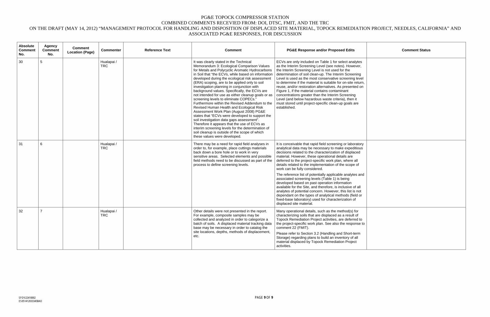
PG&E TOPOCK COMPRESSOR STATION COMBINED COMMENTS RECEVIED FROM: DOI, DTSC, FMIT, AND THE TRC
ON THE DRAFT (MAY 14, 2012) “MANAGEMENT PROTOCOL FOR HANDLING AND DISPOSITION OF DISPLACED SITE MATERIAL, TOPOCK REMEDIATION PROJECT, NEEDLES, CALIFORNIA” AND ASSOCIATED PG&E RESPONSES, FOR DISCUSSION
SFO\122410002 PAGE 9 OF 9 ES051412033345BAO
Absolute Comment No.
Agency Comment
No.
Comment Location (Page)
Commenter Reference Text Comment PG&E Response and/or Proposed Edits Comment Status
30 5 Hualapai / TRC
It was clearly stated in the Technical Memorandum 3: Ecological Comparison Values for Metals and Polycyclic Aromatic Hydrocarbons in Soil that “the ECVs, while based on information developed during the ecological risk assessment (ERA) scoping, are to be applied only to soil investigation planning in conjunction with background values. Specifically, the ECVs are not intended for use as either cleanup goals or as screening levels to eliminate COPECs.” Furthermore within the Revised Addendum to the Revised Human Health and Ecological Risk Assessment Work Plan (August 2008) PG&E states that “ECVs were developed to support the soil investigation data gaps assessment”. Therefore it appears that the use of ECVs as interim screening levels for the determination of soil cleanup is outside of the scope of which these values were developed.
ECVs are only included on Table 1 for select analytes as the Interim Screening Level (see notes). However, the Interim Screening Level is not used for the determination of soil clean-up. The Interim Screening Level is used as the most conservative screening level to determine if the material is suitable for on-site return, reuse, and/or restoration alternatives. As presented on Figure 1, if the material contains contaminant concentrations greater than the Interim Screening Level (and below hazardous waste criteria), then it must stored until project-specific clean-up goals are established.
31 6 Hualapai / TRC
There may be a need for rapid field analyses in order to, for example, place cuttings materials back down a bore hole or to work in very sensitive areas. Selected elements and possible field methods need to be discussed as part of the process to define screening levels.
It is conceivable that rapid field screening or laboratory analytical data may be necessary to make expeditious decisions related to the characterization of displaced material. However, these operational details are deferred to the project-specific work plan, where all details related to the implementation of the scope of work can be fully considered.
The reference list of potentially applicable analytes and associated screening levels (Table 1) is being developed based on past operation information available for the Site, and therefore, is inclusive of all analytes of potential concern. However, this list is not dependant on the types of analytical methods (field or fixed-base laboratory) used for characterization of displaced site material.
32 7 Hualapai / TRC
Other details were not presented in the report. For example, composite samples may be collected and analyzed in order to categorize a batch of soils. A displaced material tracking data base may be necessary in order to catalog the site locations, depths, methods of displacement, etc.
Many operational details, such as the method(s) for characterizing soils that are displaced as a result of Topock Remediation Project activities, are deferred to the project-specific work plan. See also the response to comment 22 (FMIT).
Please refer to Section 3.2 (Handling and Short-term Storage) regarding plans to build an inventory of all material displaced by Topock Remediation Project activities.

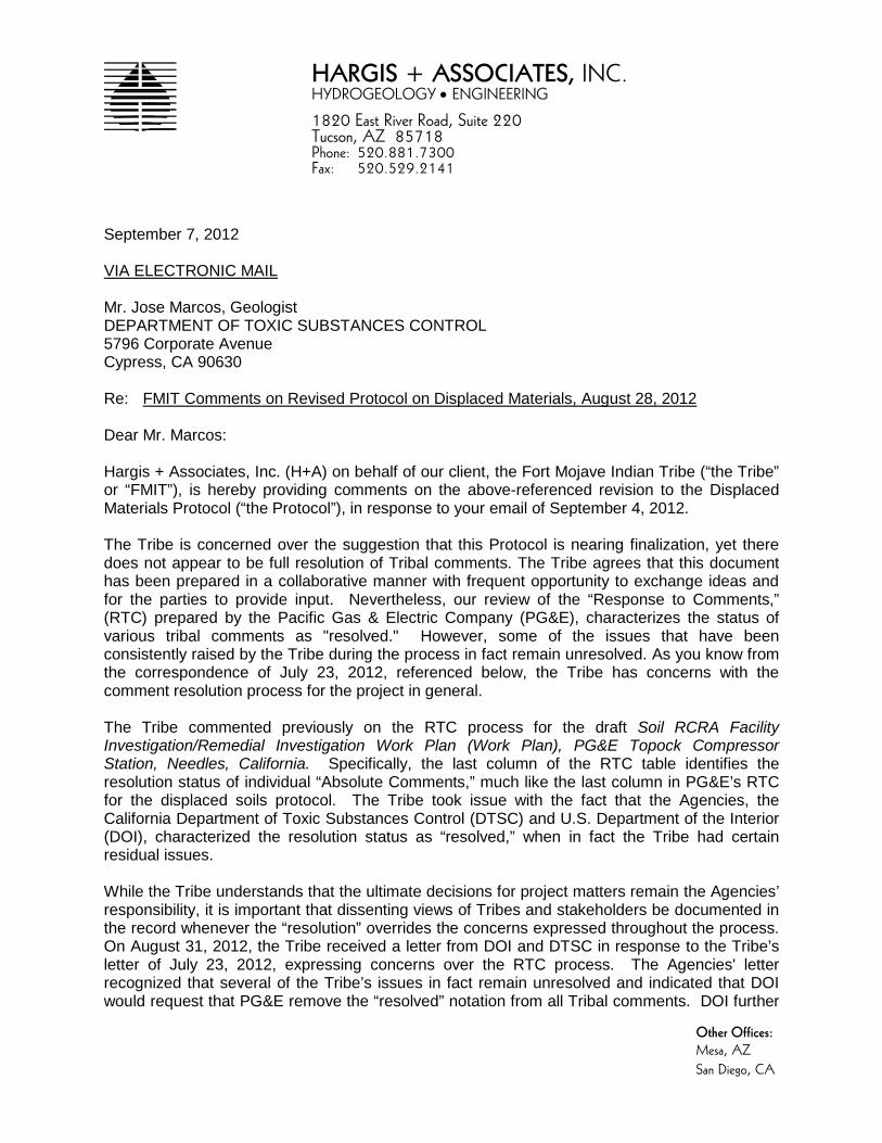
HARGIS + ASSOCIATES, INC. HYDROGEOLOGY • ENGINEERING 1820 East River Road, Suite 220 Tucson, AZ 85718 Phone: 520.881.7300 Fax: 520.529.2141
Other Offices: Mesa, AZ San Diego, CA
September 7, 2012 VIA ELECTRONIC MAIL Mr. Jose Marcos, Geologist DEPARTMENT OF TOXIC SUBSTANCES CONTROL 5796 Corporate Avenue Cypress, CA 90630 Re: FMIT Comments on Revised Protocol on Displaced Materials, August 28, 2012 Dear Mr. Marcos: Hargis + Associates, Inc. (H+A) on behalf of our client, the Fort Mojave Indian Tribe (“the Tribe” or “FMIT”), is hereby providing comments on the above-referenced revision to the Displaced Materials Protocol (“the Protocol”), in response to your email of September 4, 2012. The Tribe is concerned over the suggestion that this Protocol is nearing finalization, yet there does not appear to be full resolution of Tribal comments. The Tribe agrees that this document has been prepared in a collaborative manner with frequent opportunity to exchange ideas and for the parties to provide input. Nevertheless, our review of the “Response to Comments,” (RTC) prepared by the Pacific Gas & Electric Company (PG&E), characterizes the status of various tribal comments as "resolved." However, some of the issues that have been consistently raised by the Tribe during the process in fact remain unresolved. As you know from the correspondence of July 23, 2012, referenced below, the Tribe has concerns with the comment resolution process for the project in general. The Tribe commented previously on the RTC process for the draft Soil RCRA Facility Investigation/Remedial Investigation Work Plan (Work Plan), PG&E Topock Compressor Station, Needles, California. Specifically, the last column of the RTC table identifies the resolution status of individual “Absolute Comments,” much like the last column in PG&E’s RTC for the displaced soils protocol. The Tribe took issue with the fact that the Agencies, the California Department of Toxic Substances Control (DTSC) and U.S. Department of the Interior (DOI), characterized the resolution status as “resolved,” when in fact the Tribe had certain residual issues. While the Tribe understands that the ultimate decisions for project matters remain the Agencies’ responsibility, it is important that dissenting views of Tribes and stakeholders be documented in the record whenever the “resolution” overrides the concerns expressed throughout the process. On August 31, 2012, the Tribe received a letter from DOI and DTSC in response to the Tribe’s letter of July 23, 2012, expressing concerns over the RTC process. The Agencies' letter recognized that several of the Tribe’s issues in fact remain unresolved and indicated that DOI would request that PG&E remove the “resolved” notation from all Tribal comments. DOI further
HARGIS + ASSOCIATES, INC.
Mr. Jose Marcos September 7, 2012 Page 2 indicated its willingness to consult with the Tribe on the matter and procedure for issue resolution.
The RTC for the displaced soils protocol is unacceptable to the Tribe for the same reasons: the document seems to state that PG&E, not the Agencies, had made determinations in regard to issue resolution. This function properly belongs to the Agencies and must not be directly or indirectly delegated to a third party. Also, the document does not accurately reflect unresolved issues raised by the Tribe or document why they cannot be accommodated, if that is the case, a key part of meaningful collaboration and consultation. Perhaps finalization of the Protocol can await the Agencies' consideration of this letter and the conclusion any further discussions on this subject with the Tribes. Accordingly, below, the Tribe hereby is identifying three items where the Tribal issues remain unresolved, and requests that either these issues be resolved jointly with the Tribe(s) or the reasons why these issues cannot be accommodated at this time be identified and documented within the RTC summary. The comments are attached. Please contact me if you have questions concerning this letter. Sincerely,
HARGIS + ASSOCIATES, INC.
Leo S. Leonhart, PhD, PG, CHG Principal Hydrogeologist Comments attached below cc: K. Baker, DTSC J. Bathke, Quechan D. Bonamici, CRIT M. Cavaliere, CH2M Hill C. Coyle M. Eggers, TRC R. Escobar, Chemehuevi W. Fisher-Holt, CRIT
HARGIS + ASSOCIATES, INC.
Mr. Jose Marcos September 7, 2012 Page 3 D. Hubbs, Hualapai P. Innis, DOI L. Jackson-Kelly, Hualapai J. McCormick, Cocopah S. McDonald N. McDowell-Antone, FMIT Y. Meeks, PG&E K. Morton, Cocopah L. Otero, FMIT R. Prucha, TRC E. Rosenblum, TRC C. Schlinger, TRC M. Sullivan, CSUN T. Williams, FMIT W. Wright, TRC A. Yue, DTSC 839.07 Displaced Materials

HARGIS + ASSOCIATES, INC.
Mr. Jose Marcos September 7, 2012 Page 4
Fort Mojave Indian Tribe Comments on the Draft Soils Reuse Protocol that Remain Unresolved
Comments on the RTC
1. Comment 20 by FMIT.
There are two separate issues that have been inappropriately combined. The first issue is the Tribe’s position that this Protocol should apply to all aspects (e.g., groundwater and soil) of the Topock Remediation Project. The second issue was the request by the Tribe that the Protocol be applied to all soil-related projects. This second issue was potentially addressed by moving it to discussions between PG&E and the Tribes directly. However, this resolution does not address the first issue. Therefore, the Tribe again requests that this Protocol be applied to all aspects of the Topock Remediation Project.
2. Comment 24 by FMIT and 29 by Hualapai/TRC.
The comment and the comment’s final sentence are two separate, but related issues regarding the application of the soil criteria to decide on the disposition of disturbed soils. One issue is that it should be the final location of disturbed soil replacement that determines the applicable criteria, not the source location of the disturbed soil. And second, when the final location of disturbed soil replacement is selected, if the location has deep (i.e., below 2 feet bgs) backfill areas, and if future erosion is unlikely, then this deeper backfill soil may have less stringent acceptance criteria. While it is understood that the Protocol has criteria that are not depth-related, this issue of backfill depth can be used to decrease the amount of soil that must be removed from the site, thereby lessening the impact of the cleanup on the Site.
Comments on the August 30, 2012, Draft Protocol
1. Page 5, paragraph 6.
FMIT has commented previously that when the Protocol describes a simple comparison between the material (i.e., the disturbed soil) and the criteria, without further discussion, it gives the impression that concentration-by-concentration comparisons will be used. As discussed in the last teleconference, there may be other estimates of ‘material concentration’ that could be used (e.g., average). While the RTC specifies that the procedure for this comparison will be addressed in specific work plans, the Tribe requests that this paragraph be edited to include the statement “material concentrations will be established for each soil pile in short-term storage. This concentration may include a statistical estimate for that soil pile.” (Note: ‘pile’ may not be the correct word in this context and a substitute can be discussed.)
Department of Toxic Substances Control
Matthew Rodriquez Secretary for
Environmental Protection
Deborah O. Raphael, Director 5796 Corporate Avenue
Cypress, California 90630
Edmund G. Brown Jr.
Governor
Printed on Recycled Paper
Sent Via Electronic Mail September 18, 2012
Leo S. Leonhart, PhD, PG, CHG Principal Hydrogeologist Hargis + Associates, Inc. 1820 East River Road, Suite 220 Tucson, AZ 85718 RESPONSE TO SEPTEMBER 7, 2012 LETTER ON FMIT COMMENTS REGARDING REVISED PROTOCOL ON DISPLACED MATERIALS, PACIFIC GAS AND ELECTRIC COMPANY (PG&E), TOPOCK COMPRESSOR STATION, NEEDLES, CALIFORNIA Dear Dr. Leonhart: The Department of Toxic Substances Control (DTSC) is in receipt of your letter dated September 7, 2012, which was sent on behalf of the Fort Mojave Indian Tribe (FMIT) pertaining to the FMIT concerns over the “Management Protocol for Handling and Disposition of Displaced Site Material, Topock Remediation Project” (Protocol). DTSC appreciates the FMIT’s input as provided in your letter, and believes that they will help greatly in quickly resolving any potentially unresolved issues related to the Protocol. As you know, it has been nearly one year since your initial draft of what has evolved into the current version of the Protocol. Its development has been a collaborative effort between the various agencies, Tribes, stakeholders and PG&E as part of the displaced soil committee. The parties involved have met multiple times to discuss the details of the document and its implementation strategy. DTSC believes that these meetings throughout the past year demonstrate the commitment of all parties to completing this task and to provide meaningful input into its development. After reviewing the August 28, 2012 version of the Protocol, DTSC believes that the document has captured the issues and the resolutions suggested during the yearlong dialogues of the committee. However, in your letter, you expressed, on behalf of the FMIT, concern over DTSC’s suggestion that the Protocol is nearing completion, and your letter indicates that the response to comments (RTC) summary table does not accurately reflect unresolved issues raised by the Tribes. You specified three
Leo S. Leonhart, PhD, PG, CHG September 18, 2012 Page 2 of 4
comments that the FMIT believes remain unresolved and you requested that these issues be resolved jointly with the Tribes or document the reasons why they cannot be accommodated at this time in the RTC summary table. DTSC notes, however, that the ‘resolved’ status for comments listed on the RTC table were determined by the committee members during the various meetings after each comment was discussed. Never the less, DTSC will request PG&E to revise the RTC summary table for those three comments to reflect the FMIT’s position. DTSC is providing the following discussion to clarify our understanding of the issues raised by the three specific comments. DTSC hopes that the responses adequately address the FMIT’s comments so that the Protocol can continue to move forward. 1. Absolute Comment No. 20 by FMIT – According to the FMIT comment, the Protocol does not address soil disturbances associated with the soils investigation, and it appears that only soils displaced as a result of the groundwater remedy activities are explicitly covered. The FMIT requests that the protocol to be applied to all aspects (e.g., groundwater and soil) of the Topock Remediation Project. As indicated in the first paragraph of the Protocol, “This document presents the general approach and management protocol required for the handling and disposition of soil and/or rock (referred to as “material” throughout the document) that is displaced as a result of past (as practical), present, and future activities associated with the Pacific Gas and Electric Company (PG&E) Topock Remediation Project, Needles, California. Specifically, this includes material removed from the Earth (i.e., displaced) as a result of drilling, excavation, sampling, testing, construction, grading, and other remedial activities”. As cited, DTSC does not interpret the Protocol to be limited only to soil displaced as a result of groundwater remedy implementation. On the contrary, the scope appears to be sufficiently broad to cover all aspects of the environmental project conducted under the oversight of DTSC and the US Department of the Interior. DTSC is aware, however, that this protocol, once developed, could be submitted by PG&E to comply with a portion of Mitigation Measure CUL-1a-8 of the certified Final Environmental Impact Report where PG&E is to develop a protocol for handling soil cuttings to be included in the Cultural Impact Mitigation Program as part of the final design of the approved groundwater remedy. Currently, DTSC is in the process of conducting a California Environmental Quality Act (CEQA) evaluation for the soil investigation work plan. Based on the results of the soil CEQA evaluation, the same mitigation measure may be found to be appropriate for the soil investigation activities. Note that displaced soils from soil investigation activities will not be generated until after the soil CEQA evaluation is completed and the soil investigation work plan is approved. DTSC will instruct PG&E to add a statement in the RTC summary table reflecting DTSC’s position.
Leo S. Leonhart, PhD, PG, CHG September 18, 2012 Page 3 of 4
2. Absolute Comments No. 24 by FMIT and 29 by Hualapai/TRC – The Tribes request that the depth of the soil placement/reuse should be considered in the decision for reuse. DTSC supports PG&E’s response in the RTC summary table that separation of displaced soil to this level of detail (shallow vs. deep) greatly increases the level of complexity related to soil testing and management scenarios and could result in a larger storage footprint. The current return, reuse, and/or restoration scenarios are not depth-specific, and deeper reuse scenarios may be limited. Variables like future erosion or change in regulations also complicate two-tier reuse scenarios. More importantly, the decision to reuse soil that is above screening criteria regardless of depth ultimately rests on the respective land owners who own the land where the displaced soil will be reused. If potentially contaminated soils will be reused, the land owner must agree to a land use covenant restricting the use of their land after backfilling. DTSC believes that this issue cannot be managed at a global level since the decision is dependent on location, depth, concentration of material and landowner acceptance, DTSC believes that this issue can be deferred and handled on a case-by-case basis, potentially during the individual work plan, to first determine if there are potential locations that will require deep backfill, and more importantly, the individual land-owners preference on this issue. DTSC will instruct PG&E to revise the RTC summary table to remove the ‘resolved’ status for this comment, incorporate DTSC’s position, and indicate that additional detail can be included in the individual work plans. 3. FMIT Comment on page 5, paragraph 6 of the August 2012 draft protocol – The FMIT requests the inclusion of the statement, “material concentrations will be established for each soil pile in short-term storage. This concentration may include a statistical estimate of the soil pile”. In addition to potential concentration-by-concentration comparison between the disturbed soil and screening criteria, DTSC does not object to considering other alternative methods as long as the methods will yield data that are representative of the material in question, are in accordance with waste classification regulations, and standard practice for classifying materials such as investigation derived soil cuttings for the purposes of determining proper disposal. DTSC concurs with the approach that additional details regarding this issue can be addressed in the individual work plans. DTSC will instruct PG&E to update the Protocol and RTC summary table to incorporate the FMIT’s proposed concept as a potential alternative. Finally, your letter indicated that the FMIT has concerns with the comment resolution process for the project in general. The FMIT expressed similar concerns in a letter dated July 23, 2012. DTSC and the U.S. Department of the Interior provided a response to the FMIT letter on August 31, 2012. If you feel that this letter and the August 31, 2012 letter do not adequately address your general concerns regarding the comment resolution process for the project, we would like to meet with you to discuss any remaining concerns you may have.
Leo S. Leonhart, PhD, PG, CHG September 18, 2012 Page 4 of 4
DTSC hopes that this letter provided additional clarification and adequately addressed the FMIT’s issues related to the Protocol. As always, DTSC appreciates the Tribes and stakeholders continuing involvement on the PG&E Topock project and we look forward to working with you in moving the overall project forward. If you have any questions, please feel free to contact me at (714) 484-5492. Sincerely, Jose Marcos, PG Engineering Geologist Department of Toxic Substances Control cc: Ms. Karen Baker, DTSC Mr. John Bathke, Quechan
Mr. Douglas Bonamici, CRIT Mr. Mike Cavaliere, CH2MHill for PG&E Ms. Courtney Ann Coyle, for FMIT Ms. Margaret Eggers, TRC Mr. Ron Escobar, Chemehuevi Ms. Wilene Fisher-Holt, CRIT Mr. Christopher Guerre, DTSC Ms. Dawn Hubbs, Hualapai Ms. Pamela Innis, DOI Ms. Loretta Jackson-Kelly, Hualapai Ms. Jill McCormick, Cocopah Mr. Steven McDonald, for FMIT Ms. Nora McDowell-Antone, FMIT Ms. Yvonne Meeks, PG&E Ms. Kendra Morton, Cocopah Ms. Linda Otero, FMIT Mr. Robert Prucha, TRC Mr. Eric Rosenblum, TRC Mr. Charlie Schlinger, TRC Mr. Michael Sullivan, for FMIT Mr. Timothy Williams, FMIT Mr. Win Wright, TRC Mr. Aaron Yue, DTSC

![[DTSC] Alternatives Analysis Symposium II …dtsc.ca.gov/PollutionPrevention/.../Thompson_AAII-Presentation.pdf[DTSC] Alternatives Analysis Symposium II Chemical Compliance Systems,](https://img.pdfslide.net/doc/110x75/5ae656d97f8b9a08778cee1a/dtsc-alternatives-analysis-symposium-ii-dtsccagovpollutionpreventionthompsonaaii-.jpg)