Embed Size (px)
Citation preview
www.ijatir.org
ISSN 2348–2370
Vol.09,Issue.12,
November-2017,
Pages:2062-2070
Copyright @ 2017 IJATIR. All rights reserved.
Speed Control of Switched Reluctance Motor Powered by Photovoltaic
Energy using Fuzzy Logic Controller V. RAGHUPATHI BABU
1, M. GOWRI SHANKAR
2
1PG Scholar, Dept of EEE, KITS Engineering College, Ponnekal, Khammam(Dt), Telangana, India.
2Assistant Professor, Dept of EEE, KITS Engineering College, Ponnekal, Khammam(Dt), Telangana, India.
Abstract: The work presented in this paper concerns the
speed control of a switched reluctance motor (SRM) by use
of a Maximum Power Point Tracking (MPPT) strategy
applied to a Tri-port converter. A PV generator is used for
energy supply. Fuzzy logic control has become an important
methodology in many fields. This paper proposes a Fuzzy
Logic Controller (FLC) to control the speed of SRM motor.
The main objective of this work is to compare the operation
of PI based conventional controller and gives the effective
performance using Fuzzy Logic Control. The present work
concentrates on the design of a fuzzy logic controller for the
SRM speed control. Thus the result of applying fuzzy logic
controller to a SRM drive gives the best performance and
high robustness than a conventional PI controller. Simulation
is carried out using Matlab/Simulink.
Keywords: Electric Vehicles, Photovoltaics (PV), Power
Flow Control, Switched Reluctance Motors(SRMs), Tri-Port
Converter, Fuzzy Logic Controller.
I. INTRODUCTION
Photovoltaic Generators (PV) provide a clean and
unlimited source of energy [1-3]. As part of an ongoing
project on low-cost PV powered Electrical Vehicles, a
control system is evaluated here for a specific configuration,
based on PV panels that power a Switched Reluctance
Motor, using independent controllers for maximizing the
power supply and optimizing the operation of the motor [4].
In this paper the simulink model for the speed control of
switched reluctance motor is carried out by using different
speed controllers. The simulink models is designed for P, PI
& Fuzzy logic controller separately and their performance
result is been compared [5]. The Switched Reluctance Motor
is an electric motor which runs by a reluctance torque. For
industrial application very high speed of 50,000 rpm motor
is used [6-8]. The speed controllers applied here are based on
conventional P& PI Controller and the other one is AI based
Fuzzy Logic Controller [9]. The PI Controller proportional
integral controller) is a most special case of the PID
controller in which the derivative of the error is not being
used [10]. Fuzzy logic controller is a most intelligent
controller which uses a fuzzy logic to process the input.
Fuzzy logic is a many valued logic which is much like a
human reasoning [11].
In the industrial control FLC has various applications,
particularly where this conventional control design
techniques are very difficult to apply. A comprehensive
reviews has done for SRM machine modelling, design and
simulation and analysis and control. To provide the
maximum possible power in varying conditions, the control
system aims to regulate the PV generators so that they are
always at the Maximum PowerPoint (MPP) (which changes
with the values of solar radiation and panel temperature and
with the characteristics of the load connected to the PV)
[12]. Therefore, a Maximum Power Point Tracking (MPPT)
strategy is used in order to obtain the maximum available
power from the panel. Many methods have been developed
to determine Maximum Power Point Tracking (MPPT): This
paper considers the problem of coupling these energy
sources to power an electrical motor in an off-grid
application. When a SRM load is supplied from the PV
generator via a SEPIC converter then the duty cycle is
controlled using a specific MPPT controller. In this study,
the converter duty cycle is calculated and adjusted in order
to maximize power operation of the whole installation.
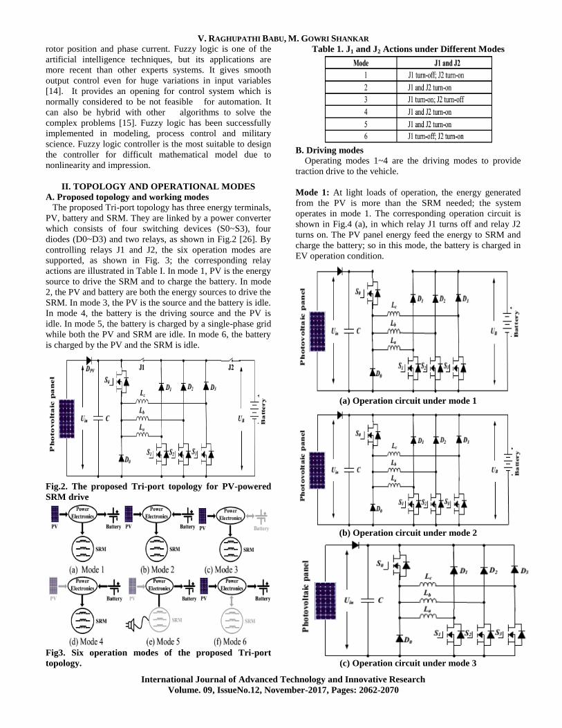
Fig1. PV-Fed Hybrid Electrical Vehicle.
The popular electronic method for torque ripple reduction
is based on the optimization of control principles. This
includes the supply voltage, turn–on and turn–off angles of
the converter and current levels [13]. But overall torque will
be reduced. Precise control of SRM model is not easy
using conventional method (like PI) as its flux linkage,
inductance, and torque possess mutual coupling with
V. RAGHUPATHI BABU, M. GOWRI SHANKAR
International Journal of Advanced Technology and Innovative Research
Volume. 09, IssueNo.12, November-2017, Pages: 2062-2070
rotor position and phase current. Fuzzy logic is one of the
artificial intelligence techniques, but its applications are
more recent than other experts systems. It gives smooth
output control even for huge variations in input variables
[14]. It provides an opening for control system which is
normally considered to be not feasible for automation. It
can also be hybrid with other algorithms to solve the
complex problems [15]. Fuzzy logic has been successfully
implemented in modeling, process control and military
science. Fuzzy logic controller is the most suitable to design
the controller for difficult mathematical model due to
nonlinearity and impression.
II. TOPOLOGY AND OPERATIONAL MODES
A. Proposed topology and working modes
The proposed Tri-port topology has three energy terminals,
PV, battery and SRM. They are linked by a power converter
which consists of four switching devices (S0~S3), four
diodes (D0~D3) and two relays, as shown in Fig.2 [26]. By
controlling relays J1 and J2, the six operation modes are
supported, as shown in Fig. 3; the corresponding relay
actions are illustrated in Table I. In mode 1, PV is the energy
source to drive the SRM and to charge the battery. In mode
2, the PV and battery are both the energy sources to drive the
SRM. In mode 3, the PV is the source and the battery is idle.
In mode 4, the battery is the driving source and the PV is
idle. In mode 5, the battery is charged by a single-phase grid
while both the PV and SRM are idle. In mode 6, the battery
is charged by the PV and the SRM is idle.
Fig.2. The proposed Tri-port topology for PV-powered
SRM drive
Fig3. Six operation modes of the proposed Tri-port
topology.
Table 1. J1 and J2 Actions under Different Modes
B. Driving modes
Operating modes 1~4 are the driving modes to provide
traction drive to the vehicle.
Mode 1: At light loads of operation, the energy generated
from the PV is more than the SRM needed; the system
operates in mode 1. The corresponding operation circuit is
shown in Fig.4 (a), in which relay J1 turns off and relay J2
turns on. The PV panel energy feed the energy to SRM and
charge the battery; so in this mode, the battery is charged in
EV operation condition.
(a) Operation circuit under mode 1
(b) Operation circuit under mode 2
(c) Operation circuit under mode 3
Speed Control of Switched Reluctance Motor Powered by Photovoltaic Energy using Fuzzy Logic Controller
International Journal of Advanced Technology and Innovative Research
Volume. 09, IssueNo.12, November-2017, Pages: 2062-2070
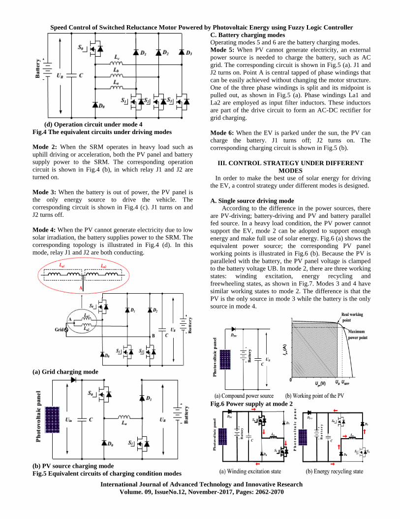
(d) Operation circuit under mode 4
Fig.4 The equivalent circuits under driving modes
Mode 2: When the SRM operates in heavy load such as
uphill driving or acceleration, both the PV panel and battery
supply power to the SRM. The corresponding operation
circuit is shown in Fig.4 (b), in which relay J1 and J2 are
turned on.
Mode 3: When the battery is out of power, the PV panel is
the only energy source to drive the vehicle. The
corresponding circuit is shown in Fig.4 (c). J1 turns on and
J2 turns off.
Mode 4: When the PV cannot generate electricity due to low
solar irradiation, the battery supplies power to the SRM. The
corresponding topology is illustrated in Fig.4 (d). In this
mode, relay J1 and J2 are both conducting.
(a) Grid charging mode
(b) PV source charging mode
Fig.5 Equivalent circuits of charging condition modes
C. Battery charging modes
Operating modes 5 and 6 are the battery charging modes.
Mode 5: When PV cannot generate electricity, an external
power source is needed to charge the battery, such as AC
grid. The corresponding circuit is shown in Fig.5 (a). J1 and
J2 turns on. Point A is central tapped of phase windings that
can be easily achieved without changing the motor structure.
One of the three phase windings is split and its midpoint is
pulled out, as shown in Fig.5 (a). Phase windings La1 and
La2 are employed as input filter inductors. These inductors
are part of the drive circuit to form an AC-DC rectifier for
grid charging.
Mode 6: When the EV is parked under the sun, the PV can
charge the battery. J1 turns off; J2 turns on. The
corresponding charging circuit is shown in Fig.5 (b).
III. CONTROL STRATEGY UNDER DIFFERENT
MODES
In order to make the best use of solar energy for driving
the EV, a control strategy under different modes is designed.
A. Single source driving mode
According to the difference in the power sources, there
are PV-driving; battery-driving and PV and battery parallel
fed source. In a heavy load condition, the PV power cannot
support the EV, mode 2 can be adopted to support enough
energy and make full use of solar energy. Fig.6 (a) shows the
equivalent power source; the corresponding PV panel
working points is illustrated in Fig.6 (b). Because the PV is
paralleled with the battery, the PV panel voltage is clamped
to the battery voltage UB. In mode 2, there are three working
states: winding excitation, energy recycling and
freewheeling states, as shown in Fig.7. Modes 3 and 4 have
similar working states to mode 2. The difference is that the
PV is the only source in mode 3 while the battery is the only
source in mode 4.
Fig.6 Power supply at mode 2
V. RAGHUPATHI BABU, M. GOWRI SHANKAR
International Journal of Advanced Technology and Innovative Research
Volume. 09, IssueNo.12, November-2017, Pages: 2062-2070
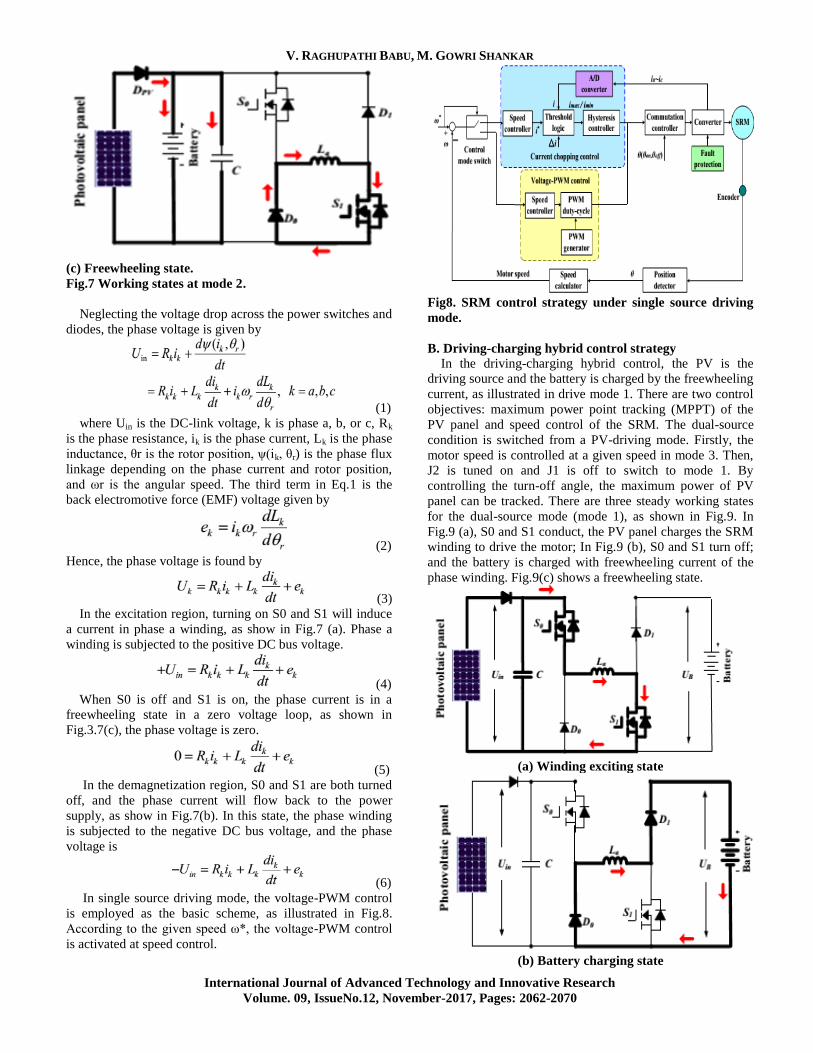
(c) Freewheeling state.
Fig.7 Working states at mode 2.
Neglecting the voltage drop across the power switches and
diodes, the phase voltage is given by
(1)
where Uin is the DC-link voltage, k is phase a, b, or c, Rk
is the phase resistance, ik is the phase current, Lk is the phase
inductance, θr is the rotor position, ψ(ik, θr) is the phase flux
linkage depending on the phase current and rotor position,
and ωr is the angular speed. The third term in Eq.1 is the
back electromotive force (EMF) voltage given by
(2)
Hence, the phase voltage is found by
(3)
In the excitation region, turning on S0 and S1 will induce
a current in phase a winding, as show in Fig.7 (a). Phase a
winding is subjected to the positive DC bus voltage.
(4)
When S0 is off and S1 is on, the phase current is in a
freewheeling state in a zero voltage loop, as shown in
Fig.3.7(c), the phase voltage is zero.
(5)
In the demagnetization region, S0 and S1 are both turned
off, and the phase current will flow back to the power
supply, as show in Fig.7(b). In this state, the phase winding
is subjected to the negative DC bus voltage, and the phase
voltage is
(6)
In single source driving mode, the voltage-PWM control
is employed as the basic scheme, as illustrated in Fig.8.
According to the given speed ω*, the voltage-PWM control
is activated at speed control.
Fig8. SRM control strategy under single source driving
mode.
B. Driving-charging hybrid control strategy
In the driving-charging hybrid control, the PV is the
driving source and the battery is charged by the freewheeling
current, as illustrated in drive mode 1. There are two control
objectives: maximum power point tracking (MPPT) of the
PV panel and speed control of the SRM. The dual-source
condition is switched from a PV-driving mode. Firstly, the
motor speed is controlled at a given speed in mode 3. Then,
J2 is tuned on and J1 is off to switch to mode 1. By
controlling the turn-off angle, the maximum power of PV
panel can be tracked. There are three steady working states
for the dual-source mode (mode 1), as shown in Fig.9. In
Fig.9 (a), S0 and S1 conduct, the PV panel charges the SRM
winding to drive the motor; In Fig.9 (b), S0 and S1 turn off;
and the battery is charged with freewheeling current of the
phase winding. Fig.9(c) shows a freewheeling state.
(a) Winding exciting state
(b) Battery charging state
Speed Control of Switched Reluctance Motor Powered by Photovoltaic Energy using Fuzzy Logic Controller
International Journal of Advanced Technology and Innovative Research
Volume. 09, IssueNo.12, November-2017, Pages: 2062-2070
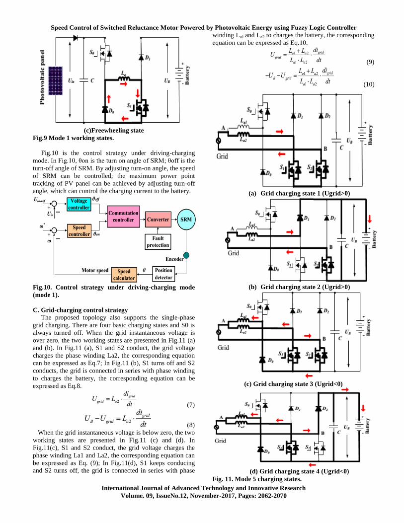
(c)Freewheeling state
Fig.9 Mode 1 working states.
Fig.10 is the control strategy under driving-charging
mode. In Fig.10, θon is the turn on angle of SRM; θoff is the
turn-off angle of SRM. By adjusting turn-on angle, the speed
of SRM can be controlled; the maximum power point
tracking of PV panel can be achieved by adjusting turn-off
angle, which can control the charging current to the battery.
Fig.10. Control strategy under driving-charging mode
(mode 1).
C. Grid-charging control strategy
The proposed topology also supports the single-phase
grid charging. There are four basic charging states and S0 is
always turned off. When the grid instantaneous voltage is
over zero, the two working states are presented in Fig.11 (a)
and (b). In Fig.11 (a), S1 and S2 conduct, the grid voltage
charges the phase winding La2, the corresponding equation
can be expressed as Eq.7; In Fig.11 (b), S1 turns off and S2
conducts, the grid is connected in series with phase winding
to charges the battery, the corresponding equation can be
expressed as Eq.8.
(7)
(8)
When the grid instantaneous voltage is below zero, the two
working states are presented in Fig.11 (c) and (d). In
Fig.11(c), S1 and S2 conduct, the grid voltage charges the
phase winding La1 and La2, the corresponding equation can
be expressed as Eq. (9); In Fig.11(d), S1 keeps conducing
and S2 turns off, the grid is connected in series with phase
winding La1 and La2 to charges the battery, the corresponding
equation can be expressed as Eq.10.
(9)
(10)
(a) Grid charging state 1 (Ugrid>0)
(b) Grid charging state 2 (Ugrid>0)
(c) Grid charging state 3 (Ugrid<0)
(d) Grid charging state 4 (Ugrid<0)
Fig. 11. Mode 5 charging states.
V. RAGHUPATHI BABU, M. GOWRI SHANKAR
International Journal of Advanced Technology and Innovative Research
Volume. 09, IssueNo.12, November-2017, Pages: 2062-2070
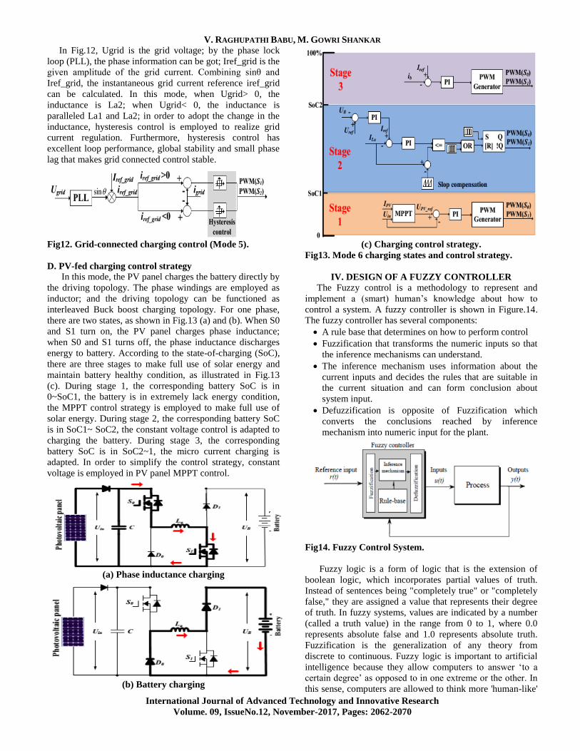
In Fig.12, Ugrid is the grid voltage; by the phase lock
loop (PLL), the phase information can be got; Iref_grid is the
given amplitude of the grid current. Combining sinθ and
Iref_grid, the instantaneous grid current reference iref_grid
can be calculated. In this mode, when Ugrid> 0, the
inductance is La2; when Ugrid< 0, the inductance is
paralleled La1 and La2; in order to adopt the change in the
inductance, hysteresis control is employed to realize grid
current regulation. Furthermore, hysteresis control has
excellent loop performance, global stability and small phase
lag that makes grid connected control stable.
Fig12. Grid-connected charging control (Mode 5).
D. PV-fed charging control strategy
In this mode, the PV panel charges the battery directly by
the driving topology. The phase windings are employed as
inductor; and the driving topology can be functioned as
interleaved Buck boost charging topology. For one phase,
there are two states, as shown in Fig.13 (a) and (b). When S0
and S1 turn on, the PV panel charges phase inductance;
when S0 and S1 turns off, the phase inductance discharges
energy to battery. According to the state-of-charging (SoC),
there are three stages to make full use of solar energy and
maintain battery healthy condition, as illustrated in Fig.13
(c). During stage 1, the corresponding battery SoC is in
0~SoC1, the battery is in extremely lack energy condition,
the MPPT control strategy is employed to make full use of
solar energy. During stage 2, the corresponding battery SoC
is in SoC1~ SoC2, the constant voltage control is adapted to
charging the battery. During stage 3, the corresponding
battery SoC is in SoC2~1, the micro current charging is
adapted. In order to simplify the control strategy, constant
voltage is employed in PV panel MPPT control.
(a) Phase inductance charging
(b) Battery charging
(c) Charging control strategy.
Fig13. Mode 6 charging states and control strategy.
IV. DESIGN OF A FUZZY CONTROLLER
The Fuzzy control is a methodology to represent and
implement a (smart) human’s knowledge about how to
control a system. A fuzzy controller is shown in Figure.14.
The fuzzy controller has several components:
A rule base that determines on how to perform control
Fuzzification that transforms the numeric inputs so that
the inference mechanisms can understand.
The inference mechanism uses information about the
current inputs and decides the rules that are suitable in
the current situation and can form conclusion about
system input.
Defuzzification is opposite of Fuzzification which
converts the conclusions reached by inference
mechanism into numeric input for the plant.
Fig14. Fuzzy Control System.
Fuzzy logic is a form of logic that is the extension of
boolean logic, which incorporates partial values of truth.
Instead of sentences being "completely true" or "completely
false," they are assigned a value that represents their degree
of truth. In fuzzy systems, values are indicated by a number
(called a truth value) in the range from 0 to 1, where 0.0
represents absolute false and 1.0 represents absolute truth.
Fuzzification is the generalization of any theory from
discrete to continuous. Fuzzy logic is important to artificial
intelligence because they allow computers to answer ‘to a
certain degree’ as opposed to in one extreme or the other. In
this sense, computers are allowed to think more 'human-like'
Speed Control of Switched Reluctance Motor Powered by Photovoltaic Energy using Fuzzy Logic Controller
International Journal of Advanced Technology and Innovative Research
Volume. 09, IssueNo.12, November-2017, Pages: 2062-2070
since almost nothing in our perception is extreme, but is true
only to a certain degree.
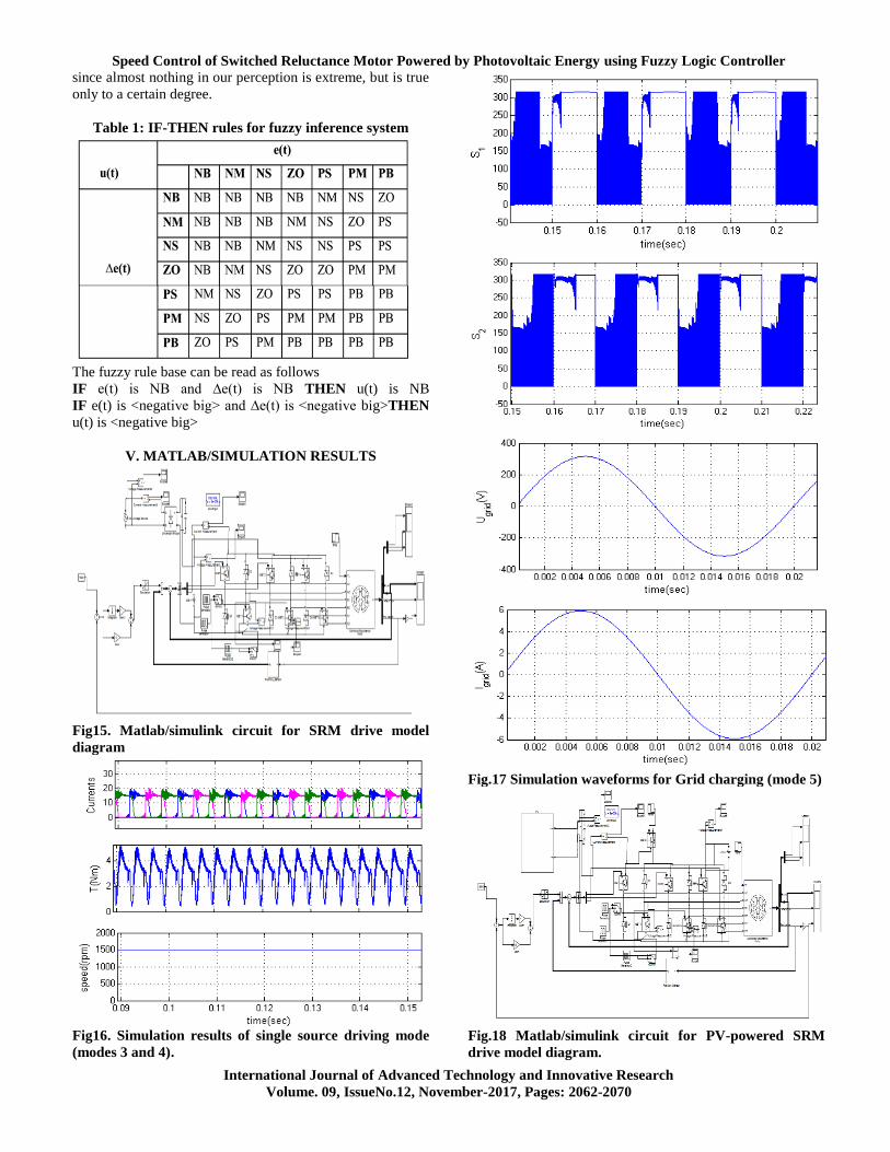
Table 1: IF-THEN rules for fuzzy inference system
The fuzzy rule base can be read as follows
IF e(t) is NB and ∆e(t) is NB THEN u(t) is NB
IF e(t) is <negative big> and ∆e(t) is <negative big>THEN
u(t) is <negative big>
V. MATLAB/SIMULATION RESULTS
Fig15. Matlab/simulink circuit for SRM drive model
diagram
Fig16. Simulation results of single source driving mode
(modes 3 and 4).
Fig.17 Simulation waveforms for Grid charging (mode 5)
Fig.18 Matlab/simulink circuit for PV-powered SRM
drive model diagram.
V. RAGHUPATHI BABU, M. GOWRI SHANKAR
International Journal of Advanced Technology and Innovative Research
Volume. 09, IssueNo.12, November-2017, Pages: 2062-2070
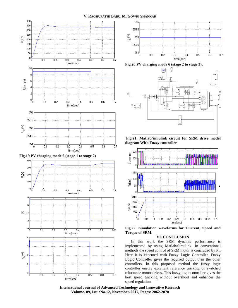
Fig.19 PV charging mode 6 (stage 1 to stage 2)
Fig.20 PV charging mode 6 (stage 2 to stage 3).
Fig.21. Matlab/simulink circuit for SRM drive model
diagram With Fuzzy controller
Fig.22. Simulation waveforms for Current, Speed and
Torque of SRM.
VI. CONCLUSION
In this work the SRM dynamic performance is
implemented by using Matlab/Simulink. In conventional
methods the speed control of SRM motor is concluded by PI.
Here it is executed with Fuzzy Logic Controller. Fuzzy
Logic Controller gives the required output than the other
controllers. In this proposed method the fuzzy logic
controller ensure excellent reference tracking of switched
reluctance motor drives. This fuzzy logic controller gives the
best speed tracking without overshoot and enhances the
speed regulation.
Speed Control of Switched Reluctance Motor Powered by Photovoltaic Energy using Fuzzy Logic Controller
International Journal of Advanced Technology and Innovative Research
Volume. 09, IssueNo.12, November-2017, Pages: 2062-2070
VII. REFERENCES
[1] A. Emadi, L. Young-Joo, K. Rajashekara, “Power
electronics and motor drives in electric, hybrid electric, and
plug-in hybrid electric vehicles,” IEEE Trans. Ind. Electron.,
vol. 55, no. 6, pp. 2237-2245, Jun. 2008.
[2] Rodrigues MG, Suemitsu WI, Branco P, Dente JA,
Rolim LGB. Fuzzy logic control of a switched reluctance
motor. Proceedings of the IEEE International Symposium.
1997,2:527–31.
[3] Nagel N. J. and Lorenz R. D., "Modeling of a
saturated switched reluctance motor using an operating
point analysis and the unsaturated equation", IEEE
Trans. Ind. Applicat., Vol. 36, pp. 714-722, May/June 2000.
[4] Z. Amjadi, S. S. Williamson, “Power-electronics-based
solutions for plugin hybrid electric vehicle energy storage
and management systems,” IEEE Trans. Ind. Electron., vol.
57, no. 2, pp. 608-616, Feb. 2010.
[5] A. Kuperman, U. Levy, J. Goren, A. Zafransky, and A.
Savernin, “Battery charger for electric vehicle traction
battery switch station,” IEEE Trans. Ind. Electron., vol. 60,
no. 12, pp. 5391-5399, Dec. 2013.
[6] S. G. Li, S. M. Sharkh, F. C. Walsh, and C. N. Zhang,
“Energy and battery management of a plug-in series hybrid
electric vehicle using fuzzy logic,” IEEE Trans. Veh.
Technol., vol. 60, no. 8, pp. 3571-3585, Oct. 2011.
[7] C. H. Kim, M. Y. Kim, and G. W. Moon, “A
modularized charge equalizer using a battery monitoring IC
for series-connected Li-Ion battery Strings in electric
vehicles,” IEEE Trans. Power Electron., vol. 28, no. 8,pp.
3779-3787, May 2013.
[8] Z. Ping, Z. Jing, L. Ranran, T. Chengde, W. Qian,
“Magnetic characteristics investigation of an axial-axial flux
compound-structure PMSM used for HEVs,” IEEE Trans.
Magnetics, vol. 46, no. 6, pp. 2191-2194, Jun. 2010.
[9] A. Kolli, O. Béthoux, A. De Bernardinis, E. Labouré, and
G. Coquery, “Space-vector PWM control synthesis for an H-
bridge drive in electric vehicles,” IEEE Trans. Veh.
Technol., vol.62, no.6, pp. 2441-2452, Jul.2013.
[10] http://www. Blue-birdelectric. Net / blue planeteco star/
solar_assisted_electric_vehicles_sustainable_transport_cars_
vans.htm
[11] S. M. Yang, and J. Y. Chen, “Controlled dynamic
braking for switched reluctance motor drives with a rectifier
front end,” IEEE Trans. Ind. Electron., vol. 60, no. 11, pp.
4913- 4919, Nov. 2013.
[12]B.Bilgin, A.Emadi, M. Krishnamurthy, “Comprehensive
evaluation of the dynamic performance of a 6/10 SRM for
traction application in PHEVs,” IEEE Trans. Ind. Electron.,
vol. 60, no. 7, pp. 2564-2575, July.2013.
[13] M. Takeno, A. Chiba, N. Hoshi, S. Ogasawara, M.
Takemoto, M. A. Rahman, “Test results and torque
improvement of the 50-kW switched reluctance motor
designed for hybrid electric vehicles,” IEEE Trans. Ind.
Appl., vol. 48, no. 4, pp. 1327-1334, Jul/Aug. 2012.
[14] A. Chiba, M. Takeno, N. Hoshi, M. Takemoto, S.
Ogasawara, M. A. Rahman, “Consideration of number of
series turns in switched-reluctance traction motor
competitive to HEV IPMSM,” IEEE Trans. Ind. Appl.,
vol.48, no. 6, pp. 2333-2340, Nov/Dec. 2012.
[15] I. Boldea, L. N. Tutelea, L. Parsa, and D. Dorrell,
“Automotive electric propulsion systems with reduced or no
permanent magnets: an overview,” IEEE Trans. Ind.
Electron., vol. 60, no. 9, pp. 5696- 5710, Oct. 2014.