Embed Size (px)
DESCRIPTION
Â
Citation preview
Studio Program, ENG & Transmission System on BTV
CHAPTER ONE
INTRODUCTION
1.1Preliminary
In 1964, Television Started broadcasting as a Corporation, named Pakistan Television
Corporation. Transmission of the station initially began from DIT (Presently RAJUK
Bhaban) for four hours duration. After independence in 1971, it was renamed as Bangladesh
Television (BTV) and continued as corporation till 1972. Then BTV was given a status of a
Department of the Government under the administration control of the Ministry of
Information. Offices and studios of Bangladesh Television were shifted to Rampur a from
DIT building on 9th February 1975. Being a state owned public broadcaster, BTV’s
administrative and financial management is under control of the Government.
In the context of Bangladesh's social perspective, the organization has earned the trust of its
viewers for which the producers, artists and supporting manpower deserve commendation for
their coordinated efforts, creativity and sincere devotion. Bangladesh Television takes pride
in recollecting the memories of 1971 when the organization inspired the nation during our
great war of liberation. BTV started Color Transmission in 1980. Since then the state-run
media is pursuing a forward looking journey. Till 2003, as many as 14 relay stations, located
all over the country, have been established. Thus 93 percent geographical area of the country
has come under transmission coverage. BTV exchanges programme and news with other
broadcasting organization on a regular basis. It is an important member of SAARC Audio
Visual Exchange Programme (SAVE) and exchanges programmes among the broadcasters of
the region. Bangladesh as a developing and peace-loving country has always extended its
hands of cooperation with other nations. BTV is an important member of several international
media bodies. As a member of Asia Pacific Broadcasting Union (ABU), Bangladesh
Television joined the Satellite News Exchange programme under ABU when it was launched
in 1984. BTV Transmits it’s transmission through 14 relay stations in the whole country,
which has a
Potential coverage of about 95% of the territory and 95% of the population. Relay
stations are as follows:
1
Natore,Sylhet,Khulna,Rangpur,Mymenshingh,Rangamati,Noakhali,.Shatkhira,Jhenidah,Thak
urgaon,B’ Beria, Patuakhali,Rajshahi,Ukhia.1
1.2 Origin of this Report
The report entitled “Studio Programe ENG & Transmission System on BTV”: A case
study on a Bangladesh Television” is the result of 4 months internship program in
Bangladesh Television , Television Bhabon Rampura, Dhaka - 1219. To complete the
internship and make this report, I had to do a literature survey on Television system, go
through history of Bangladesh Television carry out thorough study on Television system,
isolating the problems and finding out the solutions.
1.3 Organization of this Report
This report has been organized as below:
Chapter 1: In these chapter discuses about Preliminary, origin of this Report.
Chapter 2: In these chapter discuses about television overview.
Chapter 3: In these chapter discuses about BTV studio.
Chapter 4: In these chapter discuses about program studio.
Chapter 5: In these chapter discuses about programmed control room.
Chapter 6: In these chapter discuses about VTR-recording section.
Chapter 7: In these chapter discuses about Master control room.
Chapter 8: In these chapter discuses about Transmitting system of BTV.
Chapter 9: In these chapter discuses about ENG
Chapter10: Conclusion
CHAPTER TWO
TELEVISION OVERVIEW
2.1 About Bangladesh Television
2
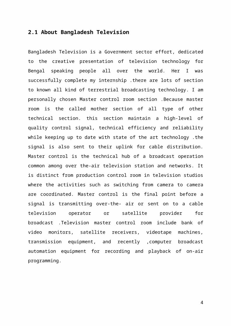
Bangladesh Television is a Government sector effort, dedicated to the creative presentation of
television technology for Bengal speaking people all over the world. Her I was successfully
complete my internship .there are lots of section to known all kind of terrestrial broadcasting
technology. I am personally chosen Master control room section .Because master room is the
called mother section of all type of other technical section. this section maintain a high-level
of quality control signal, technical efficiency and reliability while keeping up to date with
state of the art technology .the signal is also sent to their uplink for cable distribution. Master
control is the technical hub of a broadcast operation common among over the-air television
station and networks. It is distinct from production control room in television studios where
the activities such as switching from camera to camera are coordinated. Master control is the
final point before a signal is transmitting over-the- air or sent on to a cable television operator
or satellite provider for broadcast .Television master control room include bank of video
monitors, satellite receivers, videotape machines, transmission equipment, and
recently ,computer broadcast automation equipment for recording and playback of on-air
programming.
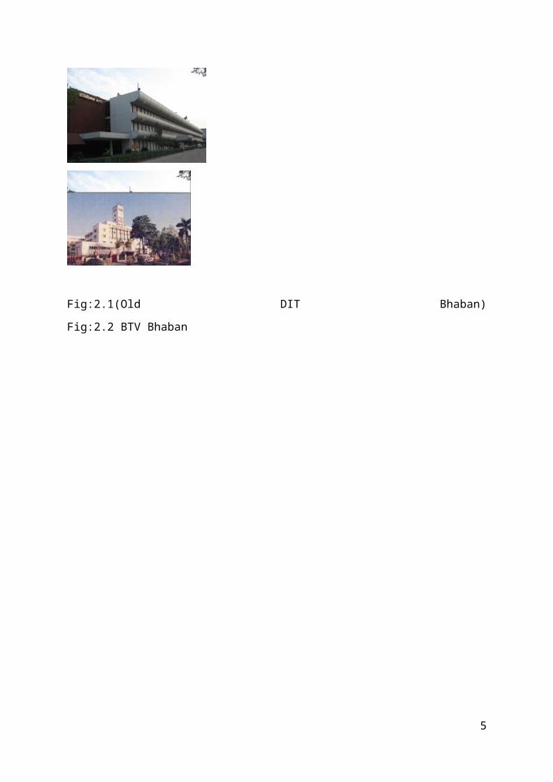
Fig:2.1(Old DIT Bhaban) Fig:2.2 BTV Bhaban
3
In 1964, Television Started broadcasting as a Corporation, named Pakistan Television
Corporation. Transmission of the station initially began from DIT (Presently RAJUK
Bhaban) for four hours duration. After independence in 1971, it was renamed as
Bangladesh Television (BTV) and continued as corporation till 1972. Then BTV was
given a status of a Department of the Information Government under the administration
control of the Ministry of. Offices and studios of Bangladesh Television were shifted to
Rampur a from DIT building on 9th February 1975. Being a state owned public
broadcaster, BTV’s administrative and financial management is under control of the
Government. In the context of Bangladesh's social perspective, the organization has
earned the trust of its viewers for which the producers, artists and supporting
manpower deserve commendation for their coordinated efforts, creativity and sincere
devotion. Bangladesh 1
BTV exchanges program me and news with other broadcasting organization on a regular
basis. It is an important member of SAARC Audio Visual Exchange Program me (SAVE)
and exchanges programmers among the broadcasters of the region. Bangladesh as a
developing and peace-loving country has always extended its hands of cooperation with other
nations. BTV is an important member of several international media bodies. As a member of
Asia Pacific Broadcasting Union (ABU), Bangladesh Television joined the Satellite News
Exchange program me under ABU when it was launched in 1984.1
2.2 Vision
The vision of the present Government of Bangladesh is to make "Digital Bangladesh" by
2021 & we are working on it. BTV has a terrestrial coverage of 95% population through 14
relay stations
BTV has a plan to go the HD Television system.
Full Automation system will be introduced in BTV
Local programme of Chittagong station will be increased from one and forty
five minutes
To six hours and also broadcast by satellite.
BTV will construct a 12 storied official building in this campus.
Bangladesh Television has adopted many projects to change the broadcasting
system
4
Bangladesh Television will change the Terrestrial broadcasting system from
Analog to Digital (DVB-T) within ITU time frame 2015.
Digital Terrestrial Transmission (DVB-T) will start from three place in
Bangladesh like Dhaka, Chittagong and Khulna experimentally very soon.1
2.3 Mission
At present, BTV transmits 17 hours terrestrial programs from 7-00 AM to till mid-night
including 14 news bulleting in English and Bengali daily. Besides, Chittagong sub-station air
one hour & forty five minute local produced programmes every day.
Bangladesh has started “BTV World” Satellite Transmission on April 11, 2004. As a result
BTV has now reaches. 1
2.4 Objectives
As a state run organization, it is accountable to the mass people of Bangladesh. It aims at the
development of the lives of the people and socio-economic progress through its creative
programs. The core objective of Bangladesh Television is to dissemination of information,
extension of education, motivation for development activities and entertainment are the major
principles followed by BTV for its broadcasting. National and international news,
documentary and development programs and various entertainment programs are aired by
BTV. For international news BTV gets supports from international News agencies and
broadcasters. On the other hand, BTV imports some foreign entertainment programs.
However, for national news, documentaries and entertainment programs, BTV produces
programs by itself. Besides, local production houses have come forward with their
productions and BTV televises the programs on terms and conditions agreed to both.1
2.5 Goals
Bangladesh Television will be the absolute media lender in the number of loans given to
large sized enterprises throughout Bangladesh. It will be a world class television in
Transmission system. BTV World is intended to extend its collaboration of reciprocal
exchange of Programmes of non-discrepant quality with any Satellite Channel in the World .1
CHAPTER THREE
5
BTV STUDIO
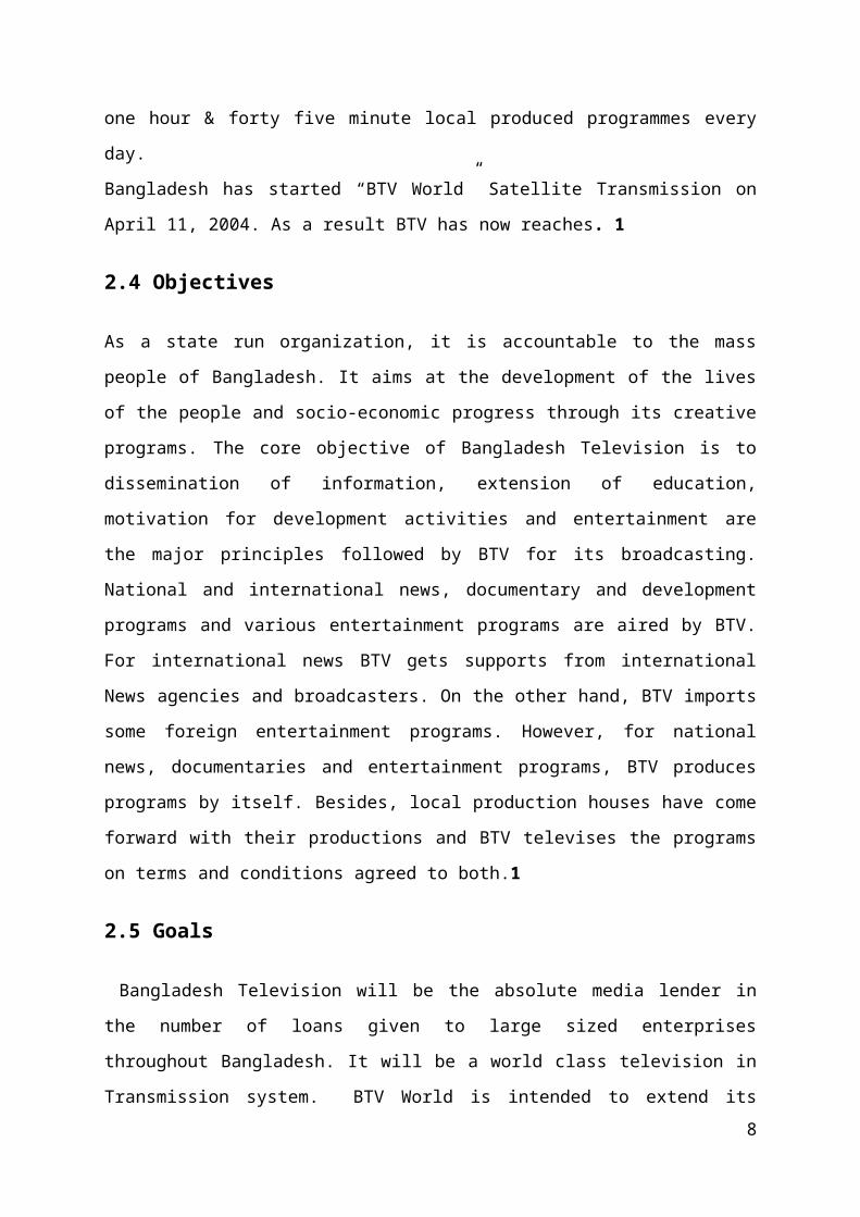
3.1 BTV News studio
Fig: 3.1 BTV news studios
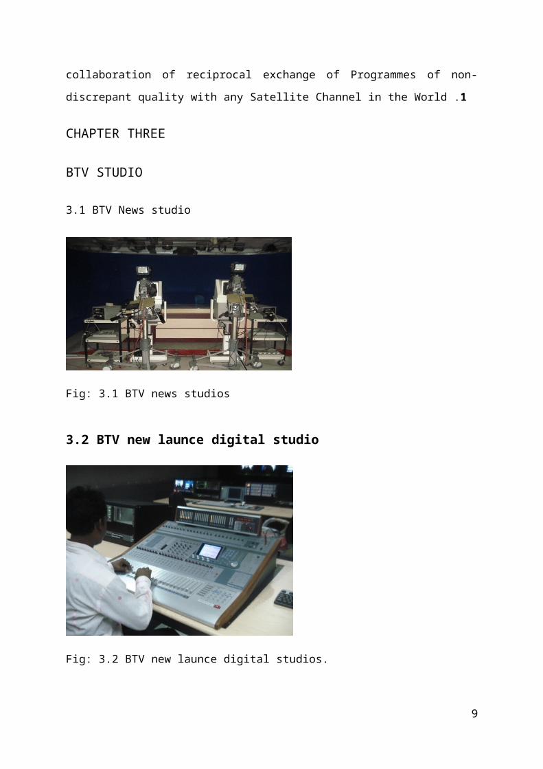
3.2 BTV new launce digital studio
Fig: 3.2 BTV new launce digital studios.
6
CHAPTER FOUR
PROGRAM STUDIO
4.1 Introduction
A complete TV Studio is in acoustically treated compact anechoic room .It is suitably
furnished and equipped with flood lights for Proper light effects. The use of dimmer stats
with flood lights enables suitable illumination level of any particular area of the studio
depending on the scene to be televised .several cameras are used to telecast the scene from
different angles similarly a large
Numbers of microphones are provided at different locations to pick up sound associated
with the programmer. The camera and microphone outputs are fed into the control room by
coaxial cables
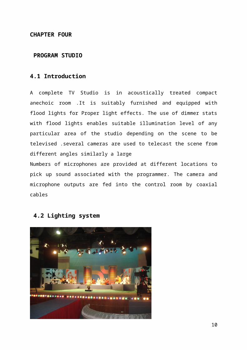
4.2 Lighting system
Fig: 4.1 lighting system
Lighting or illumination is the deliberate application of light to achieve some practical or
aesthetic effect. Lighting includes the use of both artificial light sources such as lamps and
light fixtures, as well as natural illumination by capturing daylight. Day lighting (using
windows, skylights, or light shelves) is often used as the main source of light during daytime
7
in buildings. This can save energy compared with artificial lighting, which represents a major
component of energy consumption in buildings. Without proper design, energy can be wasted
by using too much light, or using out-dated technology. Proper lighting can enhance task
performance, improve the appearance of an area, and have positive psychological effects on
occupants. One of the central dogmas of proper lighting is that a uniform illumination is
required in many applications
4.3 TV studios camera
Fig:4.2 TV studios camerasA television camera produces corresponding video signal upon receiving light from a scene
or subject. It is also called professional video cameras used for electronic motion picture
acquisition, initially developed by the television industry but now common in other
applications as well. It is known that John Logic Baird discovered Television in 1925-27, but
employing the technique of electromechanical scanning of Pal Nippon’s rotating disc. The
all-electronic television system, employing the camera tube “Iconoscope” and cathode-ray-
tube was first demonstrated by V.K. Zworykin at the Wasting House Research laboratories,
U.S.A. in 1924-29. This was the first black and white (B/W) television developed. Since then
a lot of changes and improvements were made on television camera pickup devices, its
associated electronic circuits and facility in early days comparatively bigger size television
camera employing bulky camera tube Image Orthicon (abbreviated I.O. camera) were seen in
television studios for B/W program production. This camera was then gradually replaced by
smaller size B/W TV camera, constructed using small size tubes Videocon and plumb icon.
The camera tube Videocon was in 1949, the Radio Corporation of America (RCA) developed
the first color television system compatible with monochrome or B/W television. Its system
is standardized as NTSC system. Later on modified systems SECAM in France and PAL in
Germany were introduced.
8
In the past decades we saw two varieties of television cameras. Television broadcasting
stations used more costly high quality three-tube color video camera for high quality color
television production. While, other video amateur personnel had their own less costly single
tube color video camera for video home service (VHS) production, e.g. birth-day, marriage
ceremony. Two types of professional video cameras: High end portable Camcorders used for
ENG and EFP image acquisition and studio cameras which lack the recording capability of a
camcorder, and are often fixed on studio pedestals. Professional camera with video-audio
recording facilities is called Camcorder. Camcorders are generally much larger than
consumer cameras and are designed to be carried on the shoulder. If the pickup device is a
plumb icon tube, its target plate builds up a pattern of electrical charges corresponding to the
light and shade variations in the image. An electron beam generated within the camera tube
scans this charge pattern line by line, re suiting a varying output voltage, called video signal.
4.4 Camera lensesTelevision camera can produce images to different scales depending on the focal length
(viewing angle) of the lens employed. Narrow lenses (below 200) are suitable for close-ups
of distant objects because of the magnifying effect due to their longer focal length. Lenses
with angles over 600.medium angle lenses (20 to 600) are called universal lenses and used
for television normal scenes.
4.5 Zoom lenses
Zoom lenses have a variable focal length with a range of 10:1 or more. In this lens the
viewing angel and field. View can be varied without loss of focus. A zoom lens can in
principal simulate any fixed lens which has a focal length within the zoom range. In many
camera units only a zoom lens is provided instead of the turret lens assembly. This alone
enables the camera operator to have close-ups, wide converge of the scene and distant shots
without loss to focus. Boom operators manipulate boom arms for distinct sound pick-up yet
keeping
4.6 Camera mountingCameras are mounted on light weight tripod stands with rubber wheels to enable the operator
to shift the camera as and when required. It is often necessary to be able to move the camera
up and down and around its central axis to pick-up different section of the scene. Typically
provide a 3600rotational capability and allow tilting action of plus or minus 900.
4.7 View finder
9
The camera operator to frame the scene and maintain proper Focus, an electronic, view-finder
is provided with most TV camera. This view-finder is essentially a monitor which reproduces
the scene on a small picture tube. It receives video signal from the control room stabilizing
amplifier.
4.8 Audio Pick-up
The location and placement of microphones depends on the type of programmed .A
microphone a movable platform. The booms carry microphones close to the area of pick-up
but keep them high enough to be out of the camera range
4.9 Microphone
Microphone is a device which converts sound energy into electrical energy. Without
microphone we cannot think our audio-visual production, transmission and recording
4.9.1 Kind of microphone:
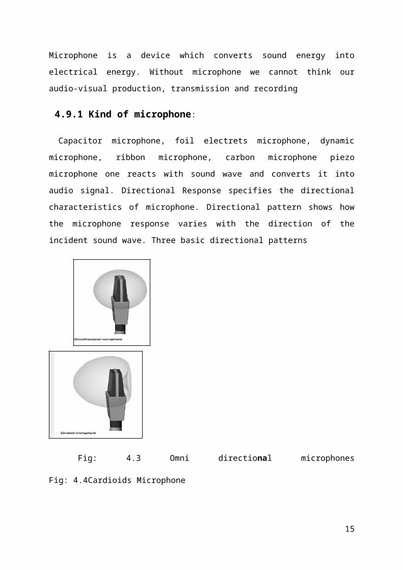
Capacitor microphone, foil electrets microphone, dynamic microphone, ribbon microphone,
carbon microphone piezo microphone one reacts with sound wave and converts it into audio
signal. Directional Response specifies the directional characteristics of microphone.
Directional pattern shows how the microphone response varies with the direction of the
incident sound wave. Three basic directional patterns
Fig: 4.3 Omni directional microphones Fig: 4.4Cardioids Microphone
10
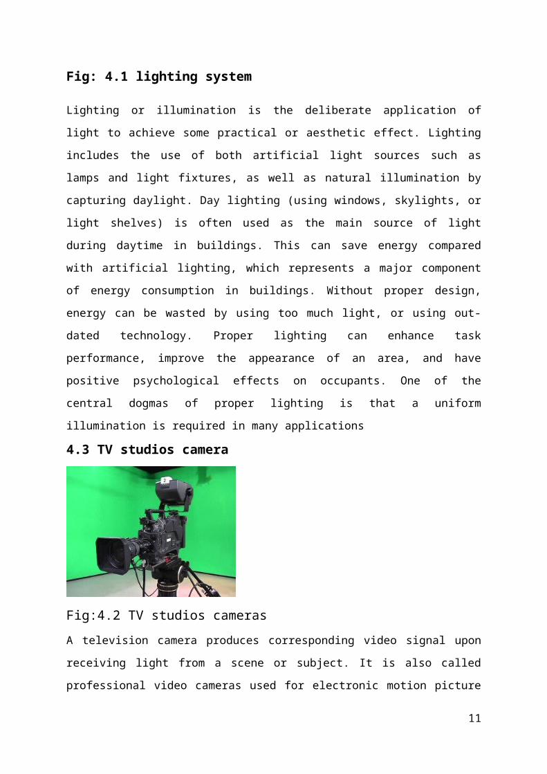
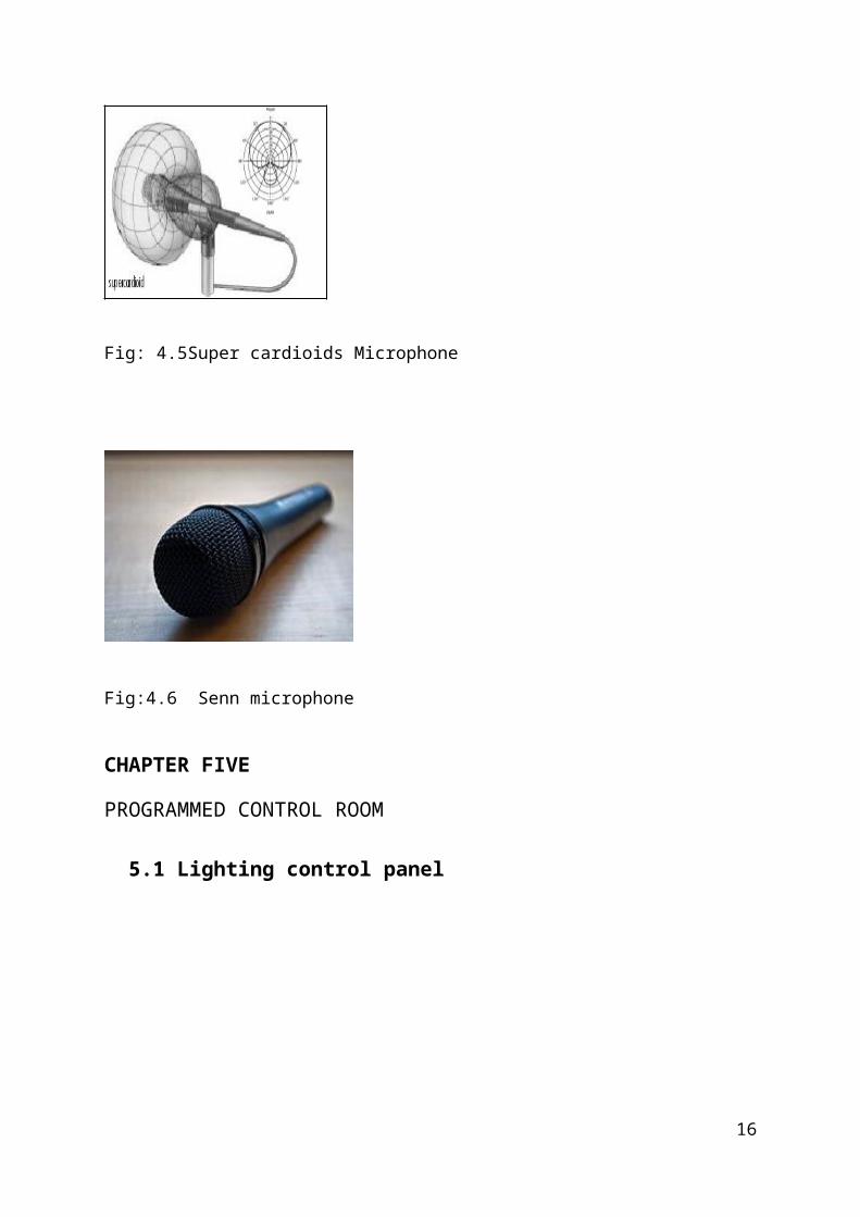
Fig: 4.5Super cardioids Microphone
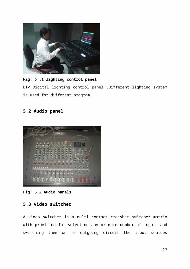
Fig:4.6 Senn microphone
CHAPTER FIVE
PROGRAMMED CONTROL ROOM
5.1 Lighting control panel
Fig: 5 .1 lighting control panel
11
BTV Digital lighting control panel .Different lighting system is used for different program.
5.2 Audio panel
Fig: 5.2 Audio panels
5.3 video switcher
A video switcher is a multi contact crossbar switcher matrix with provision for selecting any
or more number of inputs and switching them on to outgoing circuit the input sources include
cameras, VTRs and telecom outputs, besides tees signals and special effects generators
12
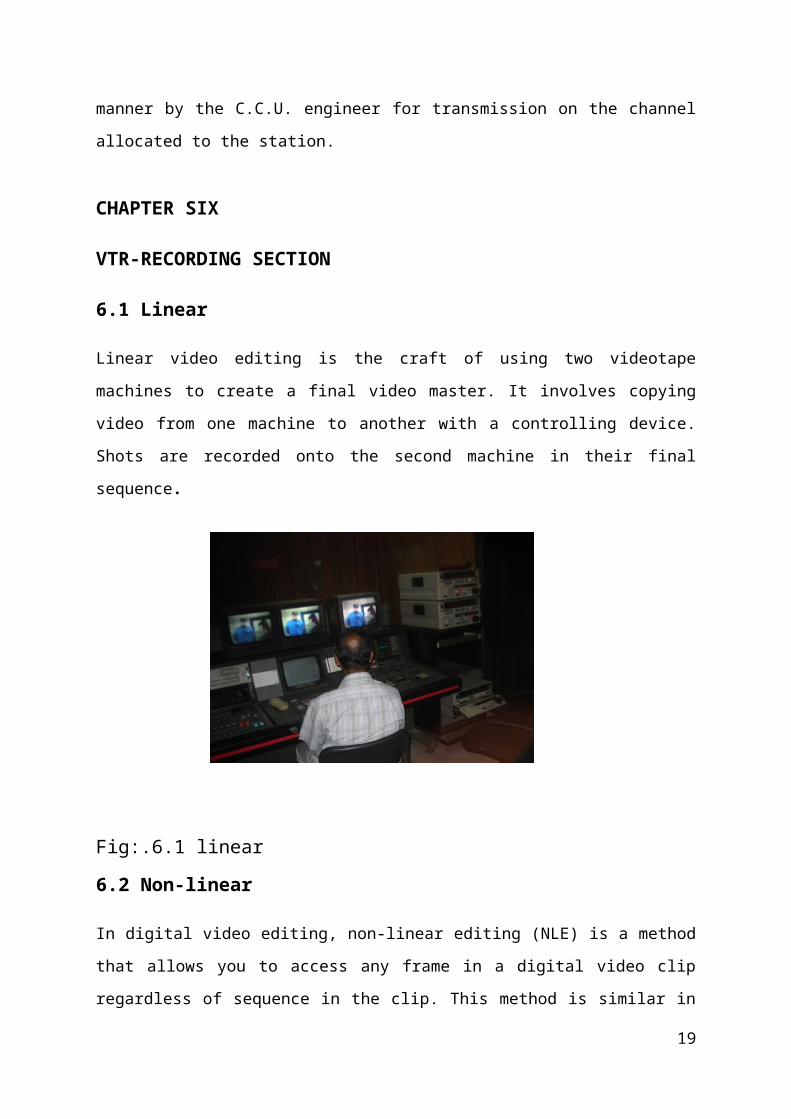
Fig:5.3 video switcher
5.4 C.C.U
The camera control unit has provision to control zoom lens action and pan-tilt movement
besides beam focus and brightness control of camera tubes .The C.C.U engineer manipulates
various controls under directions from the producer .The C.C.U. engineer has the necessary
facilities to adjust parameters such as video gain, camera sensitivity, backing level video
polarity etc .For live broadcast of programmers televised far away from the studios,
microwave links are used. The modulated composite video signal receive over the microwave
link is demodulated and processed in the usual manner by the C.C.U. engineer for
transmission on the channel allocated to the station.
CHAPTER SIX
VTR-RECORDING SECTION
6.1 Linear
Linear video editing is the craft of using two videotape machines to create a final video
master. It involves copying video from one machine to another with a controlling device.
Shots are recorded onto the second machine in their final sequence.
Fig:.6.1 linear
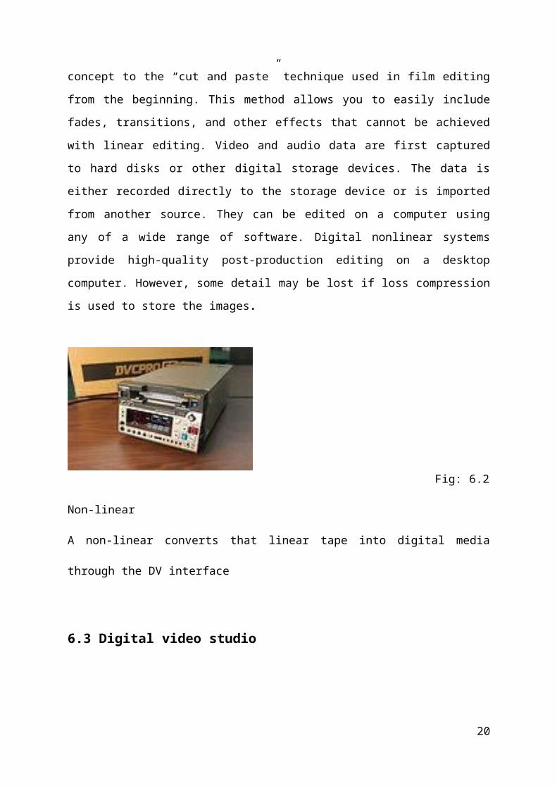
6.2 Non-linear
13
In digital video editing, non-linear editing (NLE) is a method that allows you to access any
frame in a digital video clip regardless of sequence in the clip. This method is similar in
concept to the “cut and paste” technique used in film editing from the beginning. This method
allows you to easily include fades, transitions, and other effects that cannot be achieved with
linear editing. Video and audio data are first captured to hard disks or other digital storage
devices. The data is either recorded directly to the storage device or is imported from another
source. They can be edited on a computer using any of a wide range of software. Digital
nonlinear systems provide high-quality post-production editing on a desktop computer.
However, some detail may be lost if loss compression is used to store the images.
Fig: 6.2 Non-linear
A non-linear converts that linear tape into digital media through the DV interface
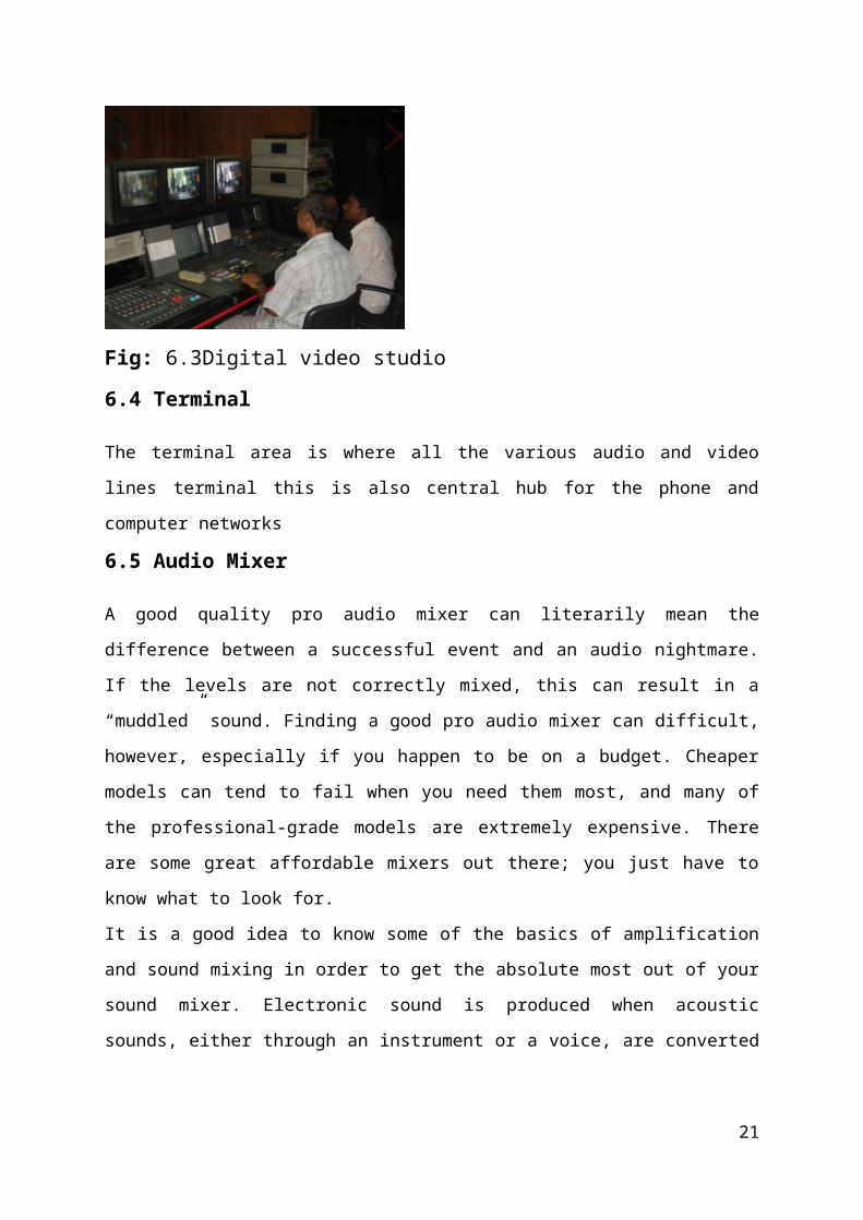
6.3 Digital video studio
Fig: 6.3Digital video studio
6.4 Terminal
14
The terminal area is where all the various audio and video lines terminal this is also central
hub for the phone and computer networks
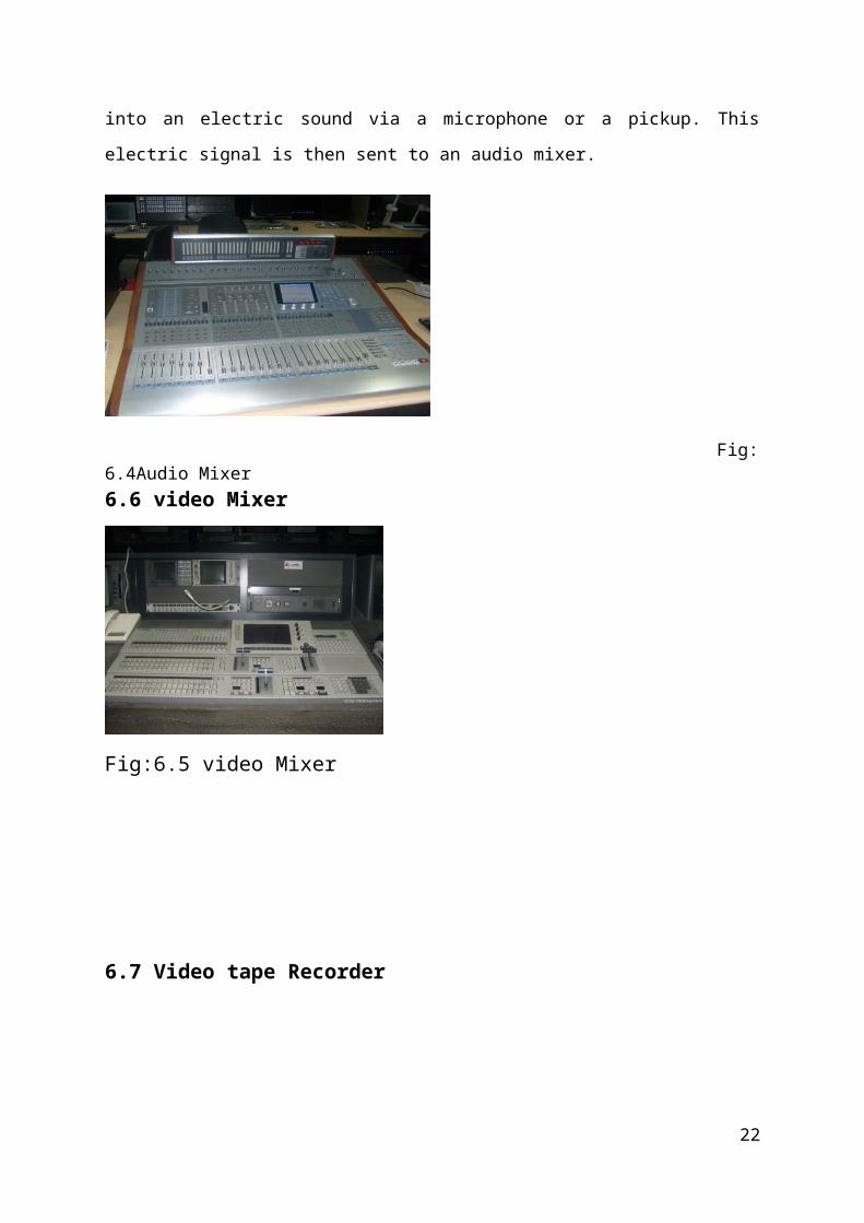
6.5 Audio Mixer
A good quality pro audio mixer can literarily mean the difference between a successful event
and an audio nightmare. If the levels are not correctly mixed, this can result in a “muddled”
sound. Finding a good pro audio mixer can difficult, however, especially if you happen to be
on a budget. Cheaper models can tend to fail when you need them most, and many of the
professional-grade models are extremely expensive. There are some great affordable mixers
out there; you just have to know what to look for.
It is a good idea to know some of the basics of amplification and sound mixing in order to get
the absolute most out of your sound mixer. Electronic sound is produced when acoustic
sounds, either through an instrument or a voice, are converted into an electric sound via a
microphone or a pickup. This electric signal is then sent to an audio mixer.
Fig: 6.4Audio Mixer6.6 video Mixer
Fig:6.5 video Mixer
15
6.7 Video tape Recorder
Fig: 6.6Video tape Recorder
There are three set of video tape recorder. A video tape recorder is a tape recorder that can
record video material. The video cassette recorder ,where the video tape is enclosed in a user
friendly video cassette shell is the most familiar type of VTR known to consumers
professionals may use other types of video tapes and recode’s.
CHAPTER 7: MASER CONTROL ROOM7.1 Introduction Master control Room
Master control is the technical hub of a broadcast operation common among most over-the-
air television stations and television networks. It is distinct from a production control room
(PCR) in television studios where the activities such as switching from camera to camera are
coordinated. A transmission control room (TCR) is usually smaller in size and is a scaled
down version of central casting. Master control is the final point before a signal is transmitted
over-the-air for terrestrial television or cablecast, satellite provider for broadcast, of sent on to
a cable television operator. Television master control rooms include banks of video monitors,
satellite receives, videotape machines, video servers, transmission equipment, and, more
recently, computer broadcast automation equipment for recording and playback of television
programming. Master control is generally staffed with one or two operators around-the-clock,
every day to ensure continuous operation. Master control operators are responsible for
16
monitoring the quality and accuracy of the on-air product, ensuring the transmission meets
government regulations, troubleshooting equipment malfunctions, and preparing
programming for play out. Regulations include both technical ones (such as those against
over-modulation and dead air), as well as content ones (such as indecency and station
ID).Many television networks and radio networks or station groups have consolidated
facilities and now operate multiple stations from one regional master control or central
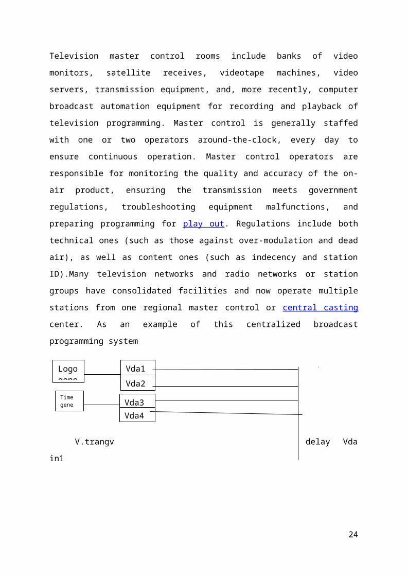
casting center. As an example of this centralized broadcast programming system
V.trangv delay Vda in1
News Pgm
Derma
SmallPST
Fig: 7.1 MCR
CHAPTER8: TRANSMITTING SYSTEM OF BTV
8.1: Terrestrial Transmitting system
Bangladesh television is terrestrial transmitting system three equipment using. Optimum
analogue liquid cooled VHF-B3 TV equipment 10K0 DD T5015 BANGLADESH
(THALES).BTV Dhaka HK transmitter. Optimum, Analogue Liquid cooled.
Optimum analogue liquid cooled VHF-B3 TV equipment 10KoDD T5015 BANGLADESH
(THALES)
17
Time gene
Vda1Vda2 Super
Processor
12
Vda1
43
Vda3
Vda2
Vda1
21 Vda7
Vda8
34
Logo gene
Vda4
Vda3Vda4
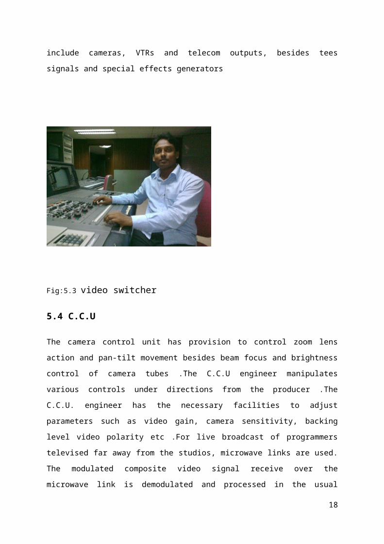
Fig: 8.1 BANGLADESH (THALES
Adjustment controls the sensitivity controls on the front of the PCL are used to set the
parameters, which are displayed by the bar graphs on the PCL and the<< RF REFLECTED
LEVEL>>AND<<RF LEVEL>> windows: These adjustments set the input signals and as
follows: R435: sensitivity control for Vision power indication
R404: sensitivity control for sound 1 power indication
R421: Sensitivity control for sound 2 powers (IRT-NICAM)
R475: sensitivity control for antenna SWR indication
R455: sensitivity control for indication of Vision SWR ahead of filter unit
R505: sensitivity control for indication of sound SWR ahead of filter unit.
Exciter section:
Video signal Input Performance
Eliminate the unwanted video Component.
Compensation of the phase distortion.
White clipping sync .stretching and clipping Pedestal Clamping.
If modulation pedestal feedback Pedestal
18
HPA-1957 Color EQ
HPA-1956 L.P.F
Hpa-1959 V.MOD
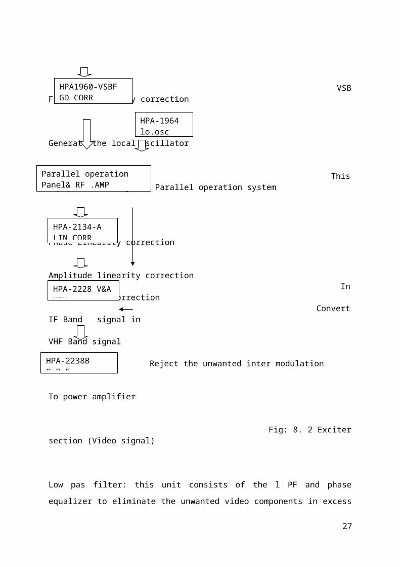
HPA1960-VSBF GD CORR
HPA-1958 VIDEO CORR
VSB Filter group Delay correction
Generate the local oscillator
This Equipment is only use Parallel operation system
Phase Linearity correction Amplitude linearity correction In demodulation correction Convert IF Band signal in VHF Band signal
Reject the unwanted inter modulation
To power amplifier
Fig: 8. 2 Exciter section (Video signal)
Low pas filter: this unit consists of the l PF and phase equalizer to eliminate the unwanted
video components in excess of 5 MHz and compensate the group delay characteristics
occurred by using of LPF.Color phase equalizer: this unit is used for compensation of the
phase distortion in the TV transmitter and receiver to achieve a high fidelity transmission of
color signals. VIDEO corrector: this unit has the following functions white clipping synch
stretching and synch. Clipping pedestal clamping. Visual modulator: the diode balanced
modulation is accomplished and the pedestal feedback circuit is included in this unit.VSBF
&CORRECTOR: This unit designed with active circuit to compensate the phase distortion
caused by VSB filter Face Linearity corrector Section: This section contains following
functions as shown: 1). Amplifier .2) phase linearity correction3) Automatics gain control
circuit V&A Mixer: This unit its used for conversion of the IF visual and aural modulated
signal to the required frequency with a local signal. Local Oscillator: This unit is used for
Supplying of the two required local signal and one frequency check output from the crystal
oscillator unit. AURAL MODULATOR: The Vari-cap diode modulation is accomplished and
the APC.(Automatic phase Control) circuit is included in this unit. REGULATED POWER
SUPPLY: This unit is employed to supply the regulated power source for exciter modules in
19
HPA-2134-A LIN.CORR
HPA-2228 V&A MIX
HPA-2238B B.P.F
HPA-1964 lo.osc
Parallel operation Panel& RF .AMP
VHF& VHF TV transmitters. Band pass filter Unit: band-pass filter is used in connection of
VHF Frequency converter to reject the unwanted inter modulation generated in the converter.
RF AMLIFIER: RF Amplifier is used mainly to small output Amplifier for TV
transmitter .This unit is designed for wide band operation or narrowband operation.40-
270MHZ.Regulated Power Supply: this unit is employed to supply the regulated power
source for transistor power amplifier unit. MAX .voltage 16v
MAX. Current 4APower Amplifier Section: This paragraph describes the transistor power
amplifier .the electron tube power amplifier the power supply circuit, and cooling system for
them
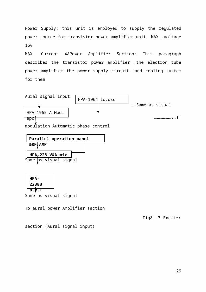
Aural signal input
….Same as visual
…………………..If modulation Automatic phase control
Same as visual signal
Same as visual signal
To aural power Amplifier section
Fig8. 3 Exciter section (Aural signal input)
The two exciter changeover modes (Dual drive version)
In the automatic changer mode the facilities for an automatic switch between the two exciters
(A-B or B-A) if a fault appears on the selected exciter channel have been enabled; in this
mode it is possible to initiate the changer over manually. In the automatic changeover mode
the identity of the selected exciter is not changed; this is not the case with manual
changeover. In the manual changeover the switch can only take place as a result of a
command from a user interface (PCL or remote user interface) Interface (PCL or remote user
interface)
Modulation:
20
HPA-1965 A.Modl apc
Parallel operation panel &RF.AMP
HPA-228 V&A mix
HPA-2238B B.P.F
HPA-1964 lo.osc
Two type of modulation are occurred in the substation. Those are audio modulation and video
modulation. Several electrical and mechanical instruments are responsible for both types of
modulation .an electrical machine named “THELES” Mainly controls the transmission section
of modulation unit in BTV .It is a air cooled solid stated (double drive) device .It used Band-
7 transmission with the Transmission power of 10kw+10kw.The exiting section of the
transmitter is 2 types such as A-exciter and B-exciter. Every type exciter has 5 modules. Two
type of modulation in BTV station discussed on the following-
Video Modulation:
In AM transmitters where efficiency is the prime requirement, amplitude modulation is
affected by making the output current of a Cass C amplifier proportion to the modulation
voltage. On the other hand, in an AM transmitter, amplitude modulation can be generated at
any point after the crystal signal oscillator .From the transmitter section of BTV the output
signal goes to “power amplification section” where rectification of amplitude modulation
signal at 557 MHz is happened in many stage .the IF stage for video signal is about 38.9 MHz
Audio Modulation:
We know that at the transmitter, the audio signal is frequency modulated and it transferred to assigned
channel sound carrier frequency by the use of multipliers .It later amplified through several stages of
power amplifier to raise the power output to desired level .Audio monitors are provided at various
point to keep a check on the sound quality .The BTV IF stage for audio signal is 33.4MHz.Though
the “THELES” performs both analog system &digital modulation in TV system ,there are
also two more electrical machine as the transmission section of BTV .One is NEC and the
other is AXCERA .The NEC is the product of Nippon Electronics of Japan, which used in
BTV .It is tube type transmitter and needs 400kw power to operate .But it is not more
efficient than previous TV transmitter THELES .The other one named AECERA ,made by
America, is the new one, which installed in the substation some months ago .it supports the
digital transmission .Now ,it is developing its for the new Gove channel “Sanged
Bangladesh” that will be lunched soon in Bangladesh Through all TV substation.
21
Amplifier:
In the TV station of the transmitter is THELES (model number: TAV 210 K0ADDB3) which
is made in France. This transmitter follows heterodyne action. It has 10 amplifiers.1st and
10th amplifiers used for video amplification .Those amplifier is missing in the transmitter
without creating any problem in total transmission system.
Mixing: we have discussed previously about this section in the signal reception and
transmission section. In this section, the video signals are both multiplexing through the
machineries by a constructive way. The machine is called the De -multiplexer .It has
transmission line .The valuable cooling system is need for the machine to work properly
always to continue the signal transmission on the through the transmission Links
Transmission: after mixing the AM and FM signal by de-multiplexer machine a path from the
machine is constructed to transmit to transmit the mixed signal .the path is made of high
Quality steel to close the occurrences of errors in line. The antenna through the transmission
line transmits the mixed signal. Those transmission equipments placed outside of the TV
station .some practical in formations of antenna and transmission line given below-
Local Oscillator:
This circuit provides a local oscillation frequency required for converting the visual and aural
I.F signals into the VHF television wave band. This oscillator multiplies twice or directly
the output from the crystal oscillator to feed it to the HPA-2228 V &A mixer (V& A Mix)
Power supply: The Dc Regulated Power supply Unit Supplies the modulation exciter with
power. This unit is equipped with a protection circuit against over voltage and over-current
for safety of the load circuit and itself.
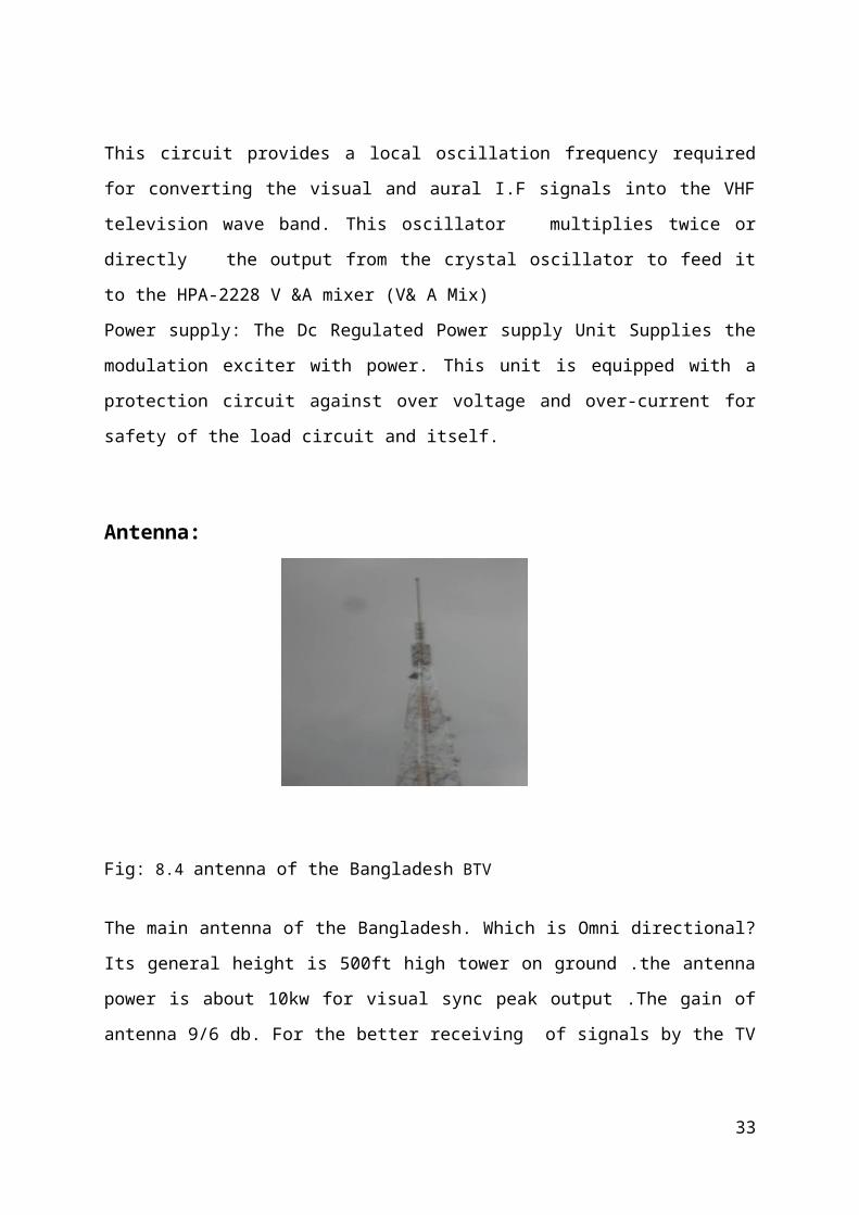
Antenna:
22
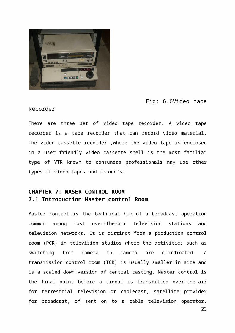
Fig: 8.4 antenna of the Bangladesh BTV
The main antenna of the Bangladesh. Which is Omni directional? Its general height is 500ft
high tower on ground .the antenna power is about 10kw for visual sync peak output .The gain
of antenna 9/6 db. For the better receiving of signals by the TV set, there must be have a
Yagi - Uda antenna on the roof or open place of the building that is called directional
antenna.
8.2 Terrestrial frequency Distribution
Terrestrial television is a mode of television broadcasting which does not involve satellite
transmission or cables — typically using radio waves through transmitting and receiving
antennas or television antenna aerials. The term is more common in Europe, while in the
United States it is referred to as broadcast television or sometimes over-the-air television
(OTA) and requires a Tuner (television) to view content. Terrestrial television broadcasting
dates back to the very beginnings of the broadcast television system as a medium itself with
the first long-distance public television broadcast from Washington, D.C., on April 7, 1927.
The BBC began broadcasting television to the public in 1929, and had a regular schedule of
television programmers in 1930. Aside from transmission by high-flying planes moving in a
loop using a system developed by Westinghouse called Stereovision, there was virtually no
other method of television delivery until the 1950s with the beginnings of cable television, or
community antenna television (CATV).
Frequency Distribution of BTVBTV uses for terrestrial broadcasting VHF band-3 Frequency (174-230 MHz)
SL.No: Station Channel No.
Power(KW) Frequency(MHz) Line description
01 Dhaka 9 10+10=20 202-209 625 Lines 50Hz02 Chittagong 5 10 174-181
03 Khulna 11 10 216-22304 Rajshahi 12 10 223-23005 Sylhet 7 10 188-195
23
06 Rangpur 6 10 181-18807 Thakurgoan 10 10 209-21608 Patuakhali 7 10 188-19509 B -baria 5 10 174-18110 Jhenaidah 5 10 174-18111 Shathkhira 7 10 188-19512 Natore 8 10 195-20213 Noakhali 12 10 223-23014 Rangamati 8 10 195-20215 Ukhia 10 10 209-21616 Mymensing 12 10 223-230
Table: 8.1 Frequency Distribution of BTV and Substations.
Satellite transmitting system
8.3 Satellite frequency distribution
Earth Station location
Latitude Longitude Satellite
Satellite location
TV Bhaban Rampura Dhaka
23º 45´56.3´´
90º 25´21.1´´
Asia Sat-3
105.5º East
Table: 8.2 Earth Station for BTV world
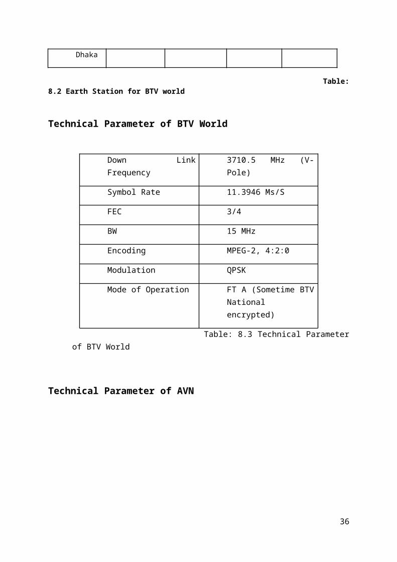
Technical Parameter of BTV World
Down Link Frequency 3710.5 MHz (V-Pole)
Symbol Rate 11.3946 Ms/S
FEC 3/4
BW 15 MHz
Encoding MPEG-2, 4:2:0
Modulation QPSK
Mode of Operation FT A (Sometime BTV National encrypted)
24
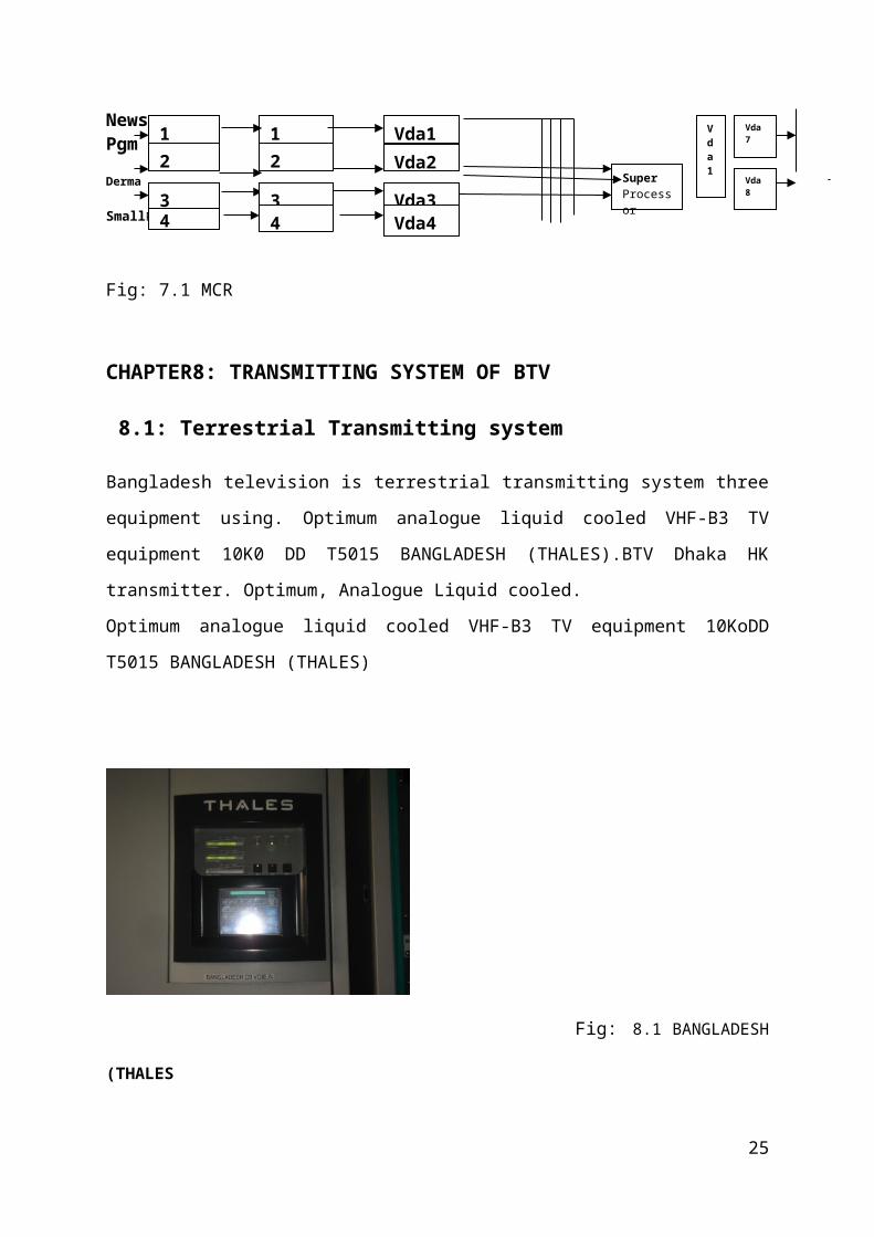
Table: 8.3 Technical Parameter of BTV World
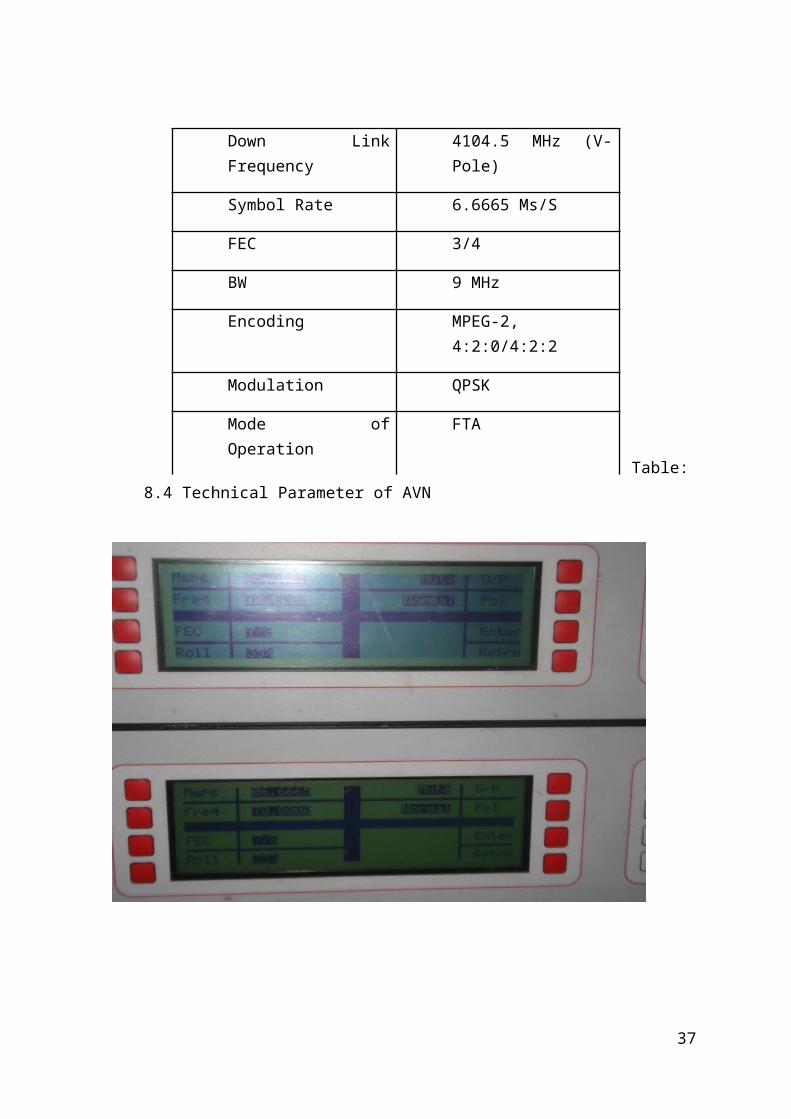
Technical Parameter of AVN
Table: 8.4 Technical Parameter of AVN
25
Down Link Frequency 4104.5 MHz (V-Pole)
Symbol Rate 6.6665 Ms/S
FEC 3/4
BW 9 MHz
Encoding MPEG-2, 4:2:0/4:2:2
Modulation QPSK
Mode of Operation FTA
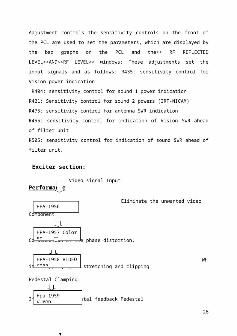
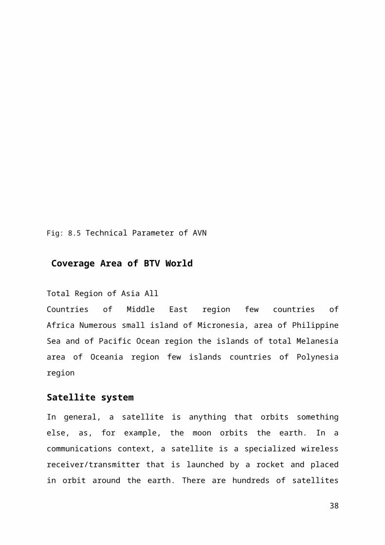
Fig: 8.5 Technical Parameter of AVN
Coverage Area of BTV World
Total Region of Asia All
Countries of Middle East region few countries of Africa Numerous small island of
Micronesia, area of Philippine Sea and of Pacific Ocean region the islands of total Melanesia
area of Oceania region few islands countries of Polynesia region
Satellite system
In general, a satellite is anything that orbits something else, as, for example, the moon orbits
the earth. In a communications context, a satellite is a specialized wireless
receiver/transmitter that is launched by a rocket and placed in orbit around the earth. There
are hundreds of satellites currently in operation. They are used for such diverse purposes as
weather forecasting, television broadcast, amateur radio communications, Internet
communications, and the Global Positioning System, (GPS).
The first artificial satellite, launched by Russia (then known as the Soviet Union) in the late
1950s, was about the size of a basketball. It did nothing but transmit a simple Morse code
signal over and over. In contrast, modern satellites can receive and re-transmit thousands of
26
signals simultaneously, from simple digital data to the most complex television
programming.
8.3.1 There are three types of communications satellite systems. A low-earth-orbit (LEO) satellite system employs a large fleet of "birds," each in a circular
orbit at a constant altitude of a few hundred miles. The orbits take the satellites over, or
nearly over, the geographic poles. Each revolution takes approximately 90 minutes to a few
hours. The fleet is arranged in such a way that, from any point on the surface at any time, at
least one satellite is on a line of sight. The entire system operates in a manner similar to the
way a cellular telephone functions. The main difference is that the transponders, or wireless
receiver/transmitters, are moving rather than fixed, and are in space rather than on the earth.
A well-designed LEO system makes it possible for anyone to access the Internet via wireless
from any point on the planet, using an antenna no more sophisticated than old-fashioned
television "rabbit ears."Some satellites revolve around the earth in elliptical orbits. These
satellites move rapidly when they are near perigee, or their lowest altitude; they move slowly
when they are near apogee, or their highest altitude. Such "birds" are used by amateur radio
operators, and by some commercial and government services. They require directional
antennas whose orientation must be constantly adjusted to follow the satellite's path across
the sky.
Satellite Ling: there are three orbital deviation in the whole world for the satellites which are
Leo (used for lower communication), MEO (used for mobile communication) and Geo (used
in TV signals transmission and reception).The Geo has 3region in the world.
Azimuth and Elevation:
27
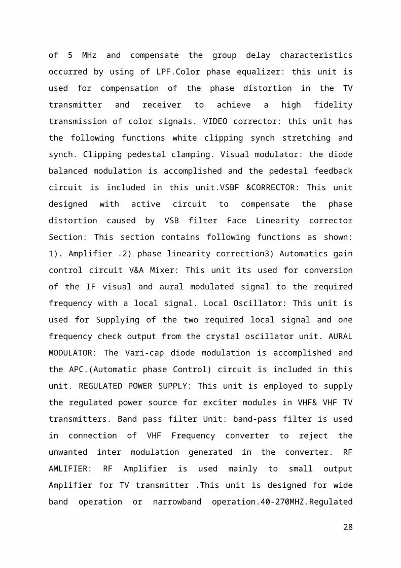
Fig: 8.6 Flyaway antenna.
Azimuth and elevation are the two basic coordinates used to determine each satellite's
position in the sky. The azimuth coordinate represents the bearing of the satellite from the site
location, while the elevation is the angle at which the antenna tilts up toward the sky .Every
geostationary satellite visible from the site location has its own unique pair of azimuth and
elevation coordinates.
Every satellite within view of a specific installation has its own unique pair of azimuth and
elevation coordinates.
Fig: 8.7 satellite instrument setup.
28
8. 3. 3 The uplink model To satellite transponder UP Converter
Baseband in FDM IF RF
RF
Fig: 8.8 the uplink modelThe primary component within the Section of a satellite system is the earth station
transmitter. Atypical earth station transmitter consists of an IF modulator, an If to RF
microwave up-converter, a high Power amplifier (HPA).THE IF modulator converters the
input baseband signal to either (mixer or BPF) converters the IF to an appropriate RF carrier
frequency. The provides adequate input sensitivity and output power to propagate the signal
to the satellite transponder. The HPA’s commonly used are klystrons and TNT’s
8.3.4The satellite transponder
A transponder is a part of a satellite, which is a combination, is a combination of transmitter
and receiver. The main function of transponder is frequency translation and amplification.
Based on the frequency translation process, there are three basic transponder configurations.
These are single conversion transponder, double conversion transponder and regenerative
Trans.
To earth station 12GHzFrom To earth station 4-12GHz
29
Mixer BPF
Microwave generator 6 or 14 GHz
HPABPFModulator (FM, PSK or QAM)
BPF MIXERLNA HPABPF
Oscillator Fig: 8.9The satellite transponder
The uplink signal is received by the receiving. The receiving signal is first band limited by
Band Pass Filter(BPF),then it is routed to low Noise Amplifier(LNA).The amplified signal is
the then frequency translated by a mixer and an oscillator. Here only the frequency is
translated from high –band up-ling frequency to the low-band down link frequency. The
mixer output (down link signal) is then applied to BPF then it is amplified by a High Power
Amplifier(HPA).This down link I s then transmitted to receiver earth station through a high
power transmitting antenna.
8.3.5The downlink:
From satellite transponder IF RF Base Band RF
Fig: 8.10The downlink
An earth station receiver includes an input BPF, an LNA and an RF to RF to IF down
converter. The BPF limits the input noise power to the LAN. The LAN is a highly sensitive,
low noise device. The RF-to-IF down converter is a mixer, BPF combination which converts
the received RF signal to an IF frequency. The most common frequencies used for satellite
communication are 6/4 and 14/12 GHz band. The first number indicates the uplink
(transponder-to-earth station) frequency and the second number is downlink (transponder-to-
earth station) frequency. Since C band is most widely used, this band is becoming
30
BPF
Mixer
Low-noise amplifier
Demodulation
BPF
Microwave generator 4-12GHz
overcrowded. A typical C band transponder can carry 12 channels, each with a bandwidth of
36MHz.
8.5 PAL, NTS C, SECAM
PAL ,short for Phase Alternating Line, Pheanase Alternation by Lime or for Phase
Alternation Line, is a color encoding used in broadcast television systems, used throughout
the world except in most of the Americas ,some East Asian countries(which use NTSC),parts
of the Middle East and Eastern Europe ,and France(which use SECAME .though most of
them are in the process of adopting PAL).PAL was developed in Germany by Walter
Brunch,working at Telefunken,and first introduction in 1967.Note that French
Thomson ,where Henri de France develop SECAM .later brought Telefunken .Thomson is
also behind the RCA is a trademark used by three now separate companies descended from a
common ancestor: the Radio COM portion of America. Various product line and business
interests of these companies now carry the RCA brand. History of RCA during World War
the pat brand for consumer electronics products, and RCA is a trademark used by three now
separate companies descended from a common ancestor. The Radio Corporation of America.
Various product line and business interests of these companies now carry the RCA band.
History of RCA during World War I the pat created the NTSC color TV standard (before
Thomson got involved).
NTSC: NTSC the analog television system in use in the United States and many other countries,
including most of the Americas and some parts of East Asia .It is named for the National
Television Systems(s)committee the industry-wide standardization body that created it .The
National Television Systems Committee was established in 1940 by the Federal
Communications Commission to resolve the conflicts which had artisan between companies
over the introduction of a nationwide analog television system in the US. The committee in
March 1941 issued a technical standard for black and white television .In January 1950 the
committee was reconstituted ,this time to decide about color television, and in March 1953 it
unanimously approved what is new called simply the NASC color television standard. The
updated standard retrained full backwards compatibility with older back and white television
31
sets. The standard has been adopted by many other countries, for example most of the
Americas and Japan.
SECAM
SECAM(Sequential Cooler avec memoire, French for “sequential color with memory ”is an
analog color television system first used in France .SECAM has been invented by a team lead
by Henri de France and working at Thomson .It is historically the European color television
standard. Thomson invented SECAM. It is, historically, the first European color television
standard.
CHAPTER-NINE
ENG
9.1 Introduction
ENG is a broadcasting (usually television) industry acronym which stands for electronic news
gathering. It can mean anything from a lone broadcast journalist reporter taking a single
professional video camera out to shoot a story, to an entire television crew taking a
production truck or satellite truck on location to do a live television news report for a remote
broadcast newscast.
The term ENG was created as television news departments moved from film based news
gathering to electronic field production (EFP) generated images on video tape. All film, of
course, required a trip through a chemical bath (processing) before it could be viewed and
edited. This generally added at least an hour from the time the film arrived back at the
television station until it was ready to be seen by the viewing public (as in the cliché "Film at
11!"). Film was also difficult to handle, subject to easy scratching and other damage. Film
editing was done by hand on what was known as "color reversal" film, meaning there was no
negative film. Edits could not be changed without cutting segments out of the film itself. It
was not that rare for the splices used for film edits to break on the air when the film was
being sent through a TV station's film chain for inclusion in newscasts. While a wonderful
medium for the creation of motion pictures and documentaries, filmmaking presented many
difficulties for use in local television news. The use of film in news gathering virtually
disappeared by the end of the 1980s.It meant that the news gathering and the reporting
process became one continuous cycle, with little pause between arriving at a news site and
32
putting the story on the air. Coupled with live microwave and/or satellite trucks, reporters
were able to show live what was happening, bringing the audience into dramatic news events.
This also led to reporters being live at news scenes long after news events had occurred, such
as a reporter standing on an empty, darkened street five hours after a fire had been
extinguished. Reporters now find themselves standing in front of empty office buildings to
add "drama" and authority to a scene that occurred many hours previously.
It can be argued that News organizations like CNN and others could not have existed
successfully during the era of film technology. As it happened, CNN began its news
transmissions in 1980, just as ENG was starting to come into its own. The technology had not
yet been fully perfected and integrated with satellites and microwave, which accounted for
some of the clumsiness of early CNN transmissions. However, ENG proved to be a crucial
development for all television news. With news recorded on U-metric 3/4" videocassette
recorders (VCR) was far easier to video edit, duplicate and distribute and, over time, control
of the technical processes passed from highly trained broadcast engineers to television
producers and television writers. This made the process less complicated, quicker and easier.
In the film era, news stories were often transferred to bulky two inch video tape for
distribution and playback, which made the content cumbersome to access, something that an
all news channels requires repeatedly. While it brought many advantages to television news
gathering and reporting, at first ENG involved considerable compromise. Contrary to popular
belief, ENG cameras and recorders were heavier and bulkier than most film equipment
9.2: OB van
33
Fig: 9.1OB VAN Fig: 9.2 production panel
The video-van's multi-camera vision mixer is ideal for covering live events with up to eight
cameras. Both 4:3 and widescreen 16:9 formats are available The mixed programmer can be
broadcast live or recorded on hard disk, DVCAM, Beta cam, DVD o any other format. The
OB van is ideal for covering outdoor events like this Scout Centenary Parade in Leeds city
centre. This 3-camera OB was relayed live onto the BBC big screen for the many spectators.
Only the front row had a direct view of the proceeding. Every else could see much better via
our via our video feed. We have since mastered and replicated 500 DVDs for them based on
this coverage.
This is a live web cast in progress from an exhibition at Stone Leigh Park. The programmer
was also recorded to broadcast standard for archiving. While there we recorded other
programming for satellite transmission. Video-Van's unique working environment has been
arrived at after extensive research and testing, giving space-efficient accommodation for
essential staff and equipment. The ergonomic design reduces stress because everything is
close to hand. While the van's exterior dimensions are compact enough to fit in a standard car
parking space. We haven't skimped on facilities, though. The Video-Van can record to any
video tape format as well as broadcasting live to satellite, the internet, or all these at once.
Streaming video via the internet is now an affordable alternative to expensive satellite links
for certain types of programming. As well as plasmas we can arrange the supply of large
screens, uplinks and other outside broad cast facilities. Here the VIDEO-VAN is connected to
a satellite uplink at the Cardiff International Arena for a live broadcast.
9.3 Electronic field production (EFP
EFP a television industry term referring to a video production which takes place in the field,
outside of a formal television studio, in a practical location or special venue. Typical
applications of electronic field production include awards shows, concerts, major newsmaker
interviews, political conventions and sporting events. Electronic field production (EFP)
places the emphasis on high-quality, multiple-camera setup photography, advanced graphics
and sound. Contrasted with the production values of EFP, in electronic journalism or
electronic news-gathering (ENG), the emphasis is on
Quickness and agility in acquisition and rapidity in the process of editing, leading to final
transmission to the audience is the goal. The two terms are often seen paired as EFP-ENG
34

and vice versa. Many episodic television shows, four-camera situation comedy, television
drama, such as PBSs Masterpiece Theatre all draw upon forms of EFP
9.4 BTV outdoor camera
Fig 9.3 BTV outdoor camera
9.5: BTV OF POWER SYSTEM
Fig: 9.4 BTV Of Power System Two power suppliers on is National Grid maintain the main power system of the BTV station and other Grid. The national grid controlled by power development Board. It supplies 10kw continuous suddenly then the substation has other option to maintain all transmission works simultaneously and that is the generator of same power 10kw.the generator placed on the ground floor of the substation building. Here the whole power system of the BTV station. observation we will say in our that it is a great achievement for us to visit a TV Station lively mainly it helps us to know about the practical and actual background of the television broadcasting in area of country with this successful TV tower .we get the information that it
35
National grid 11kw
Step down Trans former 400v
Regulated power Supply input of Thales
Power factor improvement plant
will be joined with other transmission machines soon for the channel “Sangod Bangladesh” then the people of BTV will enjoy the digital TV system at home
9.6 MW Route Ling &BTV stations
36
Rangpur T&T
Madhupur
Rangpur tvch-6
Mymensing h TV ch-12
Magura
Norgingzhi
Thakurgaon TVCh-10
Naogaon
Natore T&T
Sylhat TV ch-7
Fulbari
Dinajpur
Thakurgan T&T
Sirajgonj
Jaypurhat
Bogra
Manikgonj
Tangail
Moghbazar
Chittagong T&TSathkania
Kumira
Zeraigonj
Mohakhali
Talibabad
Hazigonj
Ramna
RAMPURA DTV, ch-9
Narayangonj
B.Baria T&T
Sylheat T&T
Shahjibazar
Moulibazar
Pabna
Rajshahi TV ch-12
Noakhali TV ch-12
B.Baria TV ch-5
Begamgonj
Barisal T&Tt&t
Sathkita TV ch-7
Chittagong TV ch-5
Faridpur
Nature TV ch-8
Kushtia
Jhenaidah
Kulna TV ch-11
jessore
Sripur
Khulna T&Tt&T
PatuakhaliTv ch-7
Rangamati ch-8
CHAPTER-10
Conclusion: BTV is a wonderful facility for learning broadcast technology. The studio
facility of BTV is highly capability for doing enamors program for people of Bangladesh.
The education and awareness program are reached to mass people very easily so that the
people can get the information and change their life at higher stage. Beside the outdoor
broadcast such as sports, international games, seminar symposium, on-demand news
gathering live broadcast can feel the audience live moment of the event. Through the
internship training in BTV is opportunity to get the maximum knowledge to change people
status of economically and politically. This internship training us the technology and
coordination of studio Program, ENG & Transmission System so clearly that makes us
confident to take the upcoming challenges.
LIST OF ABBREVIATION
B.
B.B-Black Bust
N
NTAC-National Television Systems Committee
Q
Q-Quadrature Phase-shift keying
P
PAL-Phase Alternation Line
PSTN-Public switched telephone Networks.
S
SECAM-Sequential Cooler Avec Memoire French for Sequential color With Memory.
MEO-Medium Earth Orbit.
L
LEO-Low Earth Orbit
37
Ukiya TV ch-10
Coxis Bazar T&T
Cox’s Bazar TV ch-10
Chiranga
Fig: 9.5MW Route Ling &BTV stations
H
HEO-Highly Earth Orbit.
V
VSBF-Festival Side band Frequency.
VITS-vertical information test signal.
VDA-Video Distribution Amplifiers
C
CCVS-cooler composite video signal
CCIR-Consulting committee International Radio
F
FEC-Forward error correction.
E
EFP-Electronic Field production.
Reference
1. www.btv.gov.bd
2. Instruction manual for pcn-1013BH VHF TV transmitter
3. Dilip K.Saha
4.Fundamentals of Communication-M.shamim Kiser
5. The digital satellite TV Handbook –Mark .E.Long
6. Satellite communication by D.C.Agarwal
38