Embed Size (px)
Citation preview
299
Study of Fault Clearing by A Circuit Breaker In Presence of A Shunt Capacitor Bank
Murali Kandakatla, B. Kondala Rao, Gopal Gaj jar
ABB Ltd., Maneja, Vadodara, India Thane
Introduction
Reactive power compensation through connection of shunt capacitor banks is a common practice in power transmission and distribution systems as well as in industrial power systems. The introduction of these capacitor banks also bring in many interesting phenomena in the power system that require detailed application checks for successful operations of the whole system. Generally, the capacitor switching inrush current calculation, impact on harmonics etc. are calculated as part of application check. We recently encountered one case, which points to requirement of addition of one more application check.
This paper focuses on an aspect that is rarely analyzed in detail. This phenomenon occurs during clearing of a fault on line side with presence of a capacitor bank on source side of a breaker. Usually it is beneficial to have some capacitive component on source side of breaker, as this would limit the rate of rise of transient recovery voltage after initial fault current interruptions. But if there is any re-ignition after initial interruption, then the presence of the capacitor bank would cause high frequency current superimposed on the fault current through the breaker. The energy stored in the capacitor bank is high enough to sustain such high frequency currents for duration of tens of milliseconds. The interruption by breaker at a current zero caused by superimposition of high frequency current may lead to the transient recovery voltages (TRV) beyond capability of the breaker. Eventually the breaker may fail to interrupt the fault.
It is suggested that a detailed analysis should be performed for assessing risk of occurrence of such phenomenon. There is always a possibility of having one re-ignition during fault clearing by breaker. The aim of the study should be to assess the magnitude of TRV that occurs after the interruption of current at the next
current zero after one re-ignition. If this TRV is within the breaker capability then it is suitable for application in this system, otherwise some remedial measures must be taken to avoid such possibility of breaker failures. Hence, it is much useful to perform the application check when the system is still in the planning stage so that all options can be evaluated and the risk can be averted at much lower cost.
The rest of the paper analyses the case in more detail with help of one practical medium voltage system. The system is described first and the situations where such phenomenon is expected are discussed. The simulation waveforms showing TRV are obtained and their characteristics are presented.
System Description
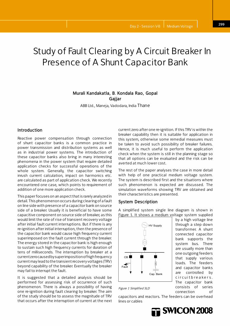
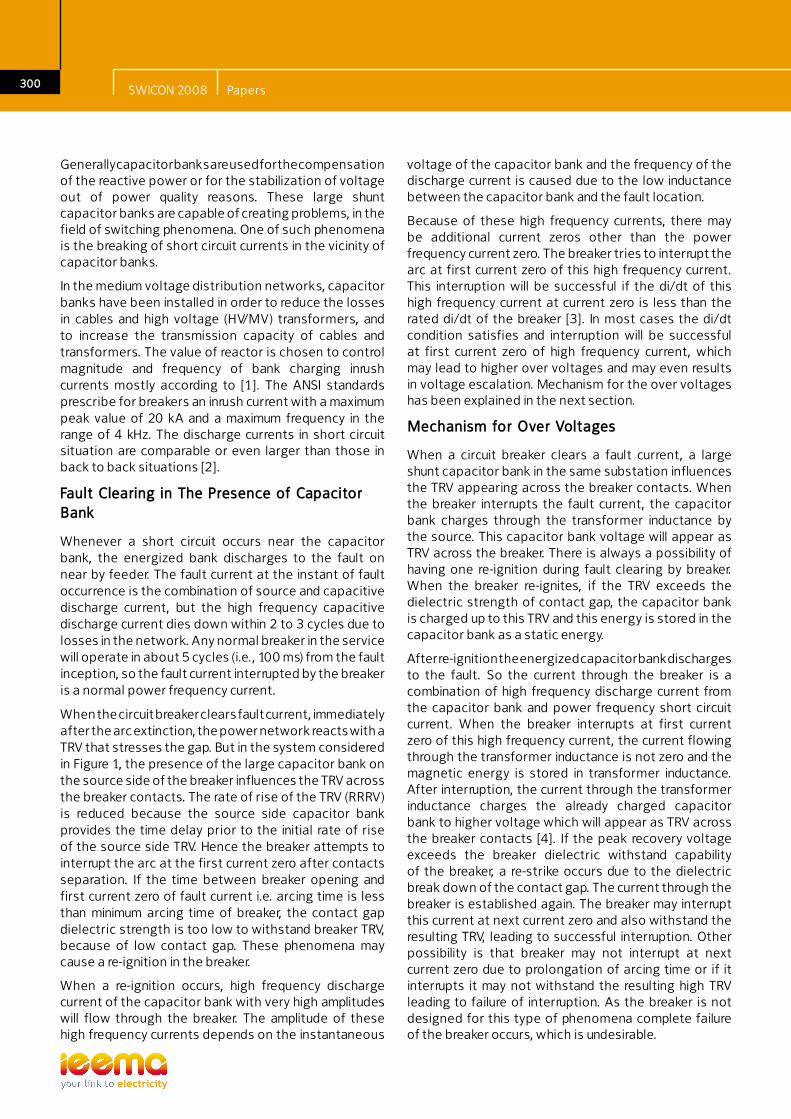
A simplified system single line diagram is shown in Figure 1. It shows a medium voltage system supplied
by a high voltage line through a step down transformer. A shunt connected capacitor bank supports the system bus. There are usually more than one outgoing feeders that supply various loads. The feeders and capacitor banks are controlled by c i r c u i t b r e a k e r s . The capacitor bank consists of series connection of
capacitors and reactors. The feeders can be overhead lines or cables
HV Supply
Cap. Bank
Fault
CB
Figure 1 Simplified SLD
Day 2 - Session V-B Medium Voltage
300
Generally capacitor banks are used for the compensation of the reactive power or for the stabilization of voltage out of power quality reasons. These large shunt capacitor banks are capable of creating problems, in the field of switching phenomena. One of such phenomena is the breaking of short circuit currents in the vicinity of capacitor banks.
In the medium voltage distribution networks, capacitor banks have been installed in order to reduce the losses in cables and high voltage (HV/MV) transformers, and to increase the transmission capacity of cables and transformers. The value of reactor is chosen to control magnitude and frequency of bank charging inrush currents mostly according to [1]. The ANSI standards prescribe for breakers an inrush current with a maximum peak value of 20 kA and a maximum frequency in the range of 4 kHz. The discharge currents in short circuit situation are comparable or even larger than those in back to back situations [2].
Fault Clearing in The Presence of Capacitor Bank
Whenever a short circuit occurs near the capacitor bank, the energized bank discharges to the fault on near by feeder. The fault current at the instant of fault occurrence is the combination of source and capacitive discharge current, but the high frequency capacitive discharge current dies down within 2 to 3 cycles due to losses in the network. Any normal breaker in the service will operate in about 5 cycles (i.e., 100 ms) from the fault inception, so the fault current interrupted by the breaker is a normal power frequency current.
When the circuit breaker clears fault current, immediately after the arc extinction, the power network reacts with a TRV that stresses the gap. But in the system considered in Figure 1, the presence of the large capacitor bank on the source side of the breaker influences the TRV across the breaker contacts. The rate of rise of the TRV (RRRV) is reduced because the source side capacitor bank provides the time delay prior to the initial rate of rise of the source side TRV. Hence the breaker attempts to interrupt the arc at the first current zero after contacts separation. If the time between breaker opening and first current zero of fault current i.e. arcing time is less than minimum arcing time of breaker, the contact gap dielectric strength is too low to withstand breaker TRV, because of low contact gap. These phenomena may cause a re-ignition in the breaker.
When a re-ignition occurs, high frequency discharge current of the capacitor bank with very high amplitudes will flow through the breaker. The amplitude of these high frequency currents depends on the instantaneous
voltage of the capacitor bank and the frequency of the discharge current is caused due to the low inductance between the capacitor bank and the fault location.
Because of these high frequency currents, there may be additional current zeros other than the power frequency current zero. The breaker tries to interrupt the arc at first current zero of this high frequency current. This interruption will be successful if the di/dt of this high frequency current at current zero is less than the rated di/dt of the breaker [3]. In most cases the di/dt condition satisfies and interruption will be successful at first current zero of high frequency current, which may lead to higher over voltages and may even results in voltage escalation. Mechanism for the over voltages has been explained in the next section.
Mechanism for Over Voltages
When a circuit breaker clears a fault current, a large shunt capacitor bank in the same substation influences the TRV appearing across the breaker contacts. When the breaker interrupts the fault current, the capacitor bank charges through the transformer inductance by the source. This capacitor bank voltage will appear as TRV across the breaker. There is always a possibility of having one re-ignition during fault clearing by breaker. When the breaker re-ignites, if the TRV exceeds the dielectric strength of contact gap, the capacitor bank is charged up to this TRV and this energy is stored in the capacitor bank as a static energy.
After re-ignition the energized capacitor bank discharges to the fault. So the current through the breaker is a combination of high frequency discharge current from the capacitor bank and power frequency short circuit current. When the breaker interrupts at first current zero of this high frequency current, the current flowing through the transformer inductance is not zero and the magnetic energy is stored in transformer inductance. After interruption, the current through the transformer inductance charges the already charged capacitor bank to higher voltage which will appear as TRV across the breaker contacts [4]. If the peak recovery voltage exceeds the breaker dielectric withstand capability of the breaker, a re-strike occurs due to the dielectric break down of the contact gap. The current through the breaker is established again. The breaker may interrupt this current at next current zero and also withstand the resulting TRV, leading to successful interruption. Other possibility is that breaker may not interrupt at next current zero due to prolongation of arcing time or if it interrupts it may not withstand the resulting high TRV leading to failure of interruption. As the breaker is not designed for this type of phenomena complete failure of the breaker occurs, which is undesirable.
SWICON 2008 Papers
30�
Application Check for A Practical System
A practical system has been considered to study the effect of shunt capacitor bank while clearing a fault on the line side of the breaker. For this system different types of faults are created on the line side of the breaker - LG, LL and LLL fault
The complete application check of fault clearing is done in PSCAD. The TRV developed across the breaker is monitored for all the test cases.
System Description
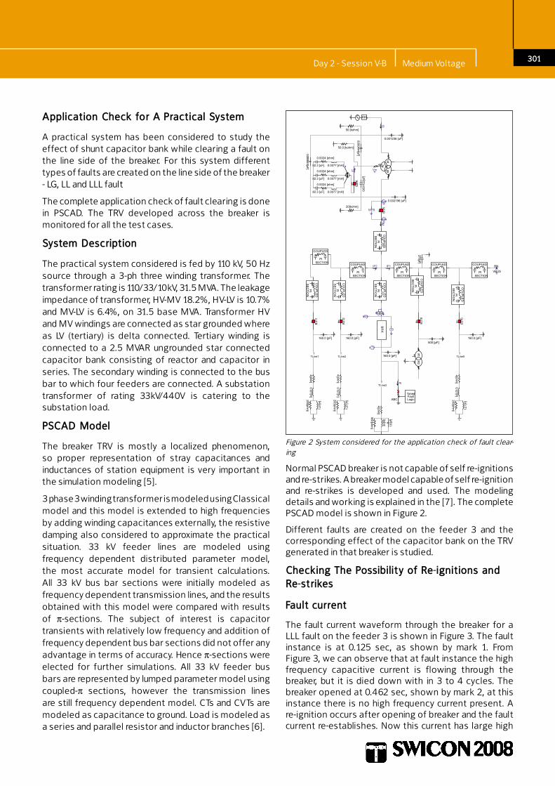
The practical system considered is fed by 110 kV, 50 Hz source through a 3-ph three winding transformer. The transformer rating is 110/33/10kV, 31.5 MVA. The leakage impedance of transformer, HV-MV 18.2%, HV-LV is 10.7% and MV-LV is 6.4%, on 31.5 base MVA. Transformer HV and MV windings are connected as star grounded where as LV (tertiary) is delta connected. Tertiary winding is connected to a 2.5 MVAR ungrounded star connected capacitor bank consisting of reactor and capacitor in series. The secondary winding is connected to the bus bar to which four feeders are connected. A substation transformer of rating 33kV/440V is catering to the substation load.
PSCAD Model
The breaker TRV is mostly a localized phenomenon, so proper representation of stray capacitances and inductances of station equipment is very important in the simulation modeling [5].
3 phase 3 winding transformer is modeled using Classical model and this model is extended to high frequencies by adding winding capacitances externally, the resistive damping also considered to approximate the practical situation. 33 kV feeder lines are modeled using frequency dependent distributed parameter model, the most accurate model for transient calculations. All 33 kV bus bar sections were initially modeled as frequency dependent transmission lines, and the results obtained with this model were compared with results of π-sections. The subject of interest is capacitor transients with relatively low frequency and addition of frequency dependent bus bar sections did not offer any advantage in terms of accuracy. Hence π-sections were elected for further simulations. All 33 kV feeder bus bars are represented by lumped parameter model using coupled-π sections, however the transmission lines are still frequency dependent model. CTs and CVTs are modeled as capacitance to ground. Load is modeled as a series and parallel resistor and inductor branches [6].
Figure 2 System considered for the application check of fault clear-ing
Normal PSCAD breaker is not capable of self re-ignitions and re-strikes. A breaker model capable of self re-ignition and re-strikes is developed and used. The modeling details and working is explained in the [7]. The complete PSCAD model is shown in Figure 2.
Different faults are created on the feeder 3 and the corresponding effect of the capacitor bank on the TRV generated in that breaker is studied.
Checking The Possibility of Re-ignitions and Re-strikes
Fault current
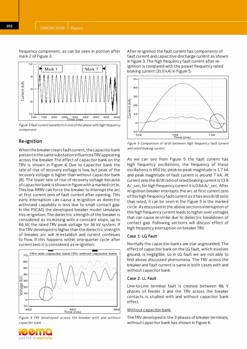
The fault current waveform through the breaker for a LLL fault on the feeder 3 is shown in Figure 3. The fault instance is at 0.125 sec, as shown by mark 1. From Figure 3, we can observe that at fault instance the high frequency capacitive current is flowing through the breaker, but it is died down with in 3 to 4 cycles. The breaker opened at 0.462 sec, shown by mark 2, at this instance there is no high frequency current present. A re-ignition occurs after opening of breaker and the fault current re-establishes. Now this current has large high
Day 2 - Session V-B Medium Voltage
302
frequency component, as can be seen in portion after mark 2 of Figure 3.
-10
0
10
20
30
40
50
60
70
462 463 464
Electrotek Concepts® TOP, The Output Processor®
Voltage (kV)
Time (ms)
TRV with capacitor bankTRV without capacitor bank
Volt
age
(kV
)
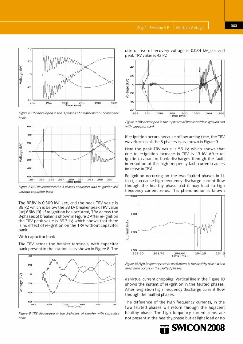
After re-ignition the fault current has components of fault current and capacitive discharge current as shown in figure 3. The high frequency fault current after re-ignition is compared with the power frequency rated braking current (31.5 kA) in Figure 5.
-10
0
10
20
30
40
50
124 129 134
Electrotek Concepts® TOP, The Output Processor®
Current (kA)
Time (ms)
Cur
ren
t (kA
)
-12
-6
0
6
12
100 150 200 250 300 350 400 450 500
Electrotek Concepts® TOP, The Output Processor®
Current (kA)
Time (ms)
Mark 111111
Mark 2
Cur
ren
t (kA
)
F igure 4 TRV develop ed across the breaker with and without
capacitor bank
Figure 5 Comparison of di/dt between high frequency fault current
and rated braking current
As we can see from Figure 5 the fault current has high frequency oscillations, the frequency of these oscillations is 650 Hz, peak-to-peak magnitude is 1.7 kA and peak magnitude of fault current is around 7 kA. At current zero the di/dt ratio of rated braking current is 13.9 A/_sec, for high frequency current it is 0.64 A/_sec. After re-ignition breaker interrupts the arc at first current zero of this high frequency fault current as it has less di/dt ratio than rated, it can be seen in the Figure 5 in the marked circle. As discussed in the above sections interruption of this high frequency current leads to higher over voltages that can cause re-strike due to dielectric breakdown of contact gap. Following sections will discuss effect of high frequency interruption on breaker TRV.
Case �: LG Fault
Normally the capacitor banks are star ungrounded. The effect of capacitor bank on the LG fault, which involves ground, is negligible, so in LG fault we are not able to find above discussed phenomena. The TRV across the breaker and fault current is same in both cases with and without capacitor bank.
Case 2: LL Fault
Line-to-Line terminal fault is created between R& Y phases of feeder 3 and the TRV across the breaker contacts is studied with and without capacitor bank effect.
Without capacitor bank
The TRV developed in the 3-phases of breaker terminals, without capacitor bank has shown in Figure 6.
Figure 3 Fault current waveform in one of the phase with high frequency component
Re-ignition
When the breaker clears fault current, the capacitor bank present in the same substation influences TRV appearing across the breaker. The effect of capacitor bank on the TRV is shown in Figure 4. Due to capacitor bank the rate of rise of recovery voltage is low, but peak of the recovery voltage is higher than without capacitor bank [8]. The lower rate of rise of recovery voltage because of capacitor bank is shown in figure with a marked circle. This low RRRV can force the breaker to interrupt the arc at first current zero of fault current after opening. This early interruption can cause a re-ignition as dielectric withstand capability is less due to small contact gap. In the PSCAD, the developed breaker model simulates this re-ignition. The dielectric strength of the breaker is considered as increasing with a constant slope, up to 66 kV, the rated TRV peak voltage for 36 kV system. If the TRV developed is higher than the dielectric strength of breaker, arc will re-establish and current continues to flow. If this happens within one-quarter cycle after current zero it is considered as re-ignition.
SWICON 2008 Papers
303
rate of rise of recovery voltage is 0.034 kV/_sec and peak TRV value is 43 kV.
The RRRV is 0.309 kV/_sec, and the peak TRV value is 38 kV, which is below the 33 kV breaker peak TRV value (uc) 66kV [9]. If re-ignition has occurred, TRV across the 3-phases of breaker is shown in Figure 7. After re-ignition the TRV peak value is 39.3 kV, which shows that there is no effect of re-ignition on the TRV without capacitor bank.
With capacitor bank
The TRV across the breaker terminals, with capacitor bank present in the station is as shown in Figure 8. The
-40
-20
0
20
40
252 254 256 258 260 262
Electrotek Concepts® TOP, The Output Processor®
Voltage (kV)
Time (ms)
Volt
age
(kV
)
-60
-40
-20
0
20
40
60
251 253 255 257 259 261 263 265 267
Electrotek Concepts® TOP, The Output Processor®
Voltage (kV)
Time (ms)
Volt
age
(kV
)
-60
-40
-20
0
20
40
252 254 256 258 260 262
Electrotek Concepts® TOP, The Output Processor®
Voltage (kV)
Time (ms)
Volt
age
(kV
)
Volt
age
(kV
)
-60
-40
-20
0
20
40
60
252 254 256 258 260 262 264 266
Electrotek Concepts® TOP, The Output Processor®
Voltage (kV)
Time (ms)
-0.06
-0.03
0.00
0.03
253.50 253.75 254.00 254.25 254.50
Electrotek Concepts® TOP, The Output Processor®
Current (kA)
Time (ms)
Cur
ren
t (kA
)
Figure 6 TRV developed in the 3-phases of breaker without capacitor
bank
Figure 7 TRV developed in the 3-phases of breaker with re-ignition and
without capacitor bank
Figure 8 TRV developed in the 3-phases of breaker with capacitor bank
Figure 9 TRV developed in the 3-phases of breaker with re-ignition and with capacitor bank
Figure 10 High frequency current oscillations in the healthy phase when re-ignition occurs in the faulted phases.
If re-ignition occurs because of low arcing time, the TRV waveform in all the 3-phases is as shown in Figure 9.
Here the peak TRV value is 56 kV, which shows that due to re-ignition increase in TRV is 13 kV. After re-ignition, capacitor bank discharges through the fault, interruption of this high frequency fault current causes increase in TRV.
Re-ignition occurring on the two faulted phases in LL fault, can cause high frequency discharge current flow through the healthy phase and it may lead to high frequency current zeros. This phenomenon is known
as virtual current chopping. Vertical line in the Figure 10 shows the instant of re-ignition in the faulted phases. After re-ignition high frequency discharge current flow through the faulted phases.
The difference of the high frequency currents, in the two faulted phases will return through the adjacent healthy phase. The high frequency current zeros are not present in the healthy phase but at light load or no
Day 2 - Session V-B Medium Voltage
30�
load conditions these high frequency current zeros may present and lead to increase in the TRV.
The effect of capacitor bank on the breaker TRV under LL fault can be understood by the above simulation results. The RRRV with capacitor bank is lower than without capacitor bank and the effect of re-ignition on the TRV is more in the case of with capacitor bank.
-45
-30
-15
0
15
30
45
60
460 463 466 469 472 475
Electrotek Concepts® TOP, The Output Processor®
Voltage (kV)
Time (ms)
Volt
age
(kA
)Vo
ltag
e (k
A)
-70
-50
-30
-10
10
30
50
70
459 461 463 465 467 469 471 473
Electrotek Concepts® TOP, The Output Processor®
Voltage (kV)
Time (ms)
up to 61.5 kV, which is below the specfied TRV peak of the breaker.
With capacitor bank
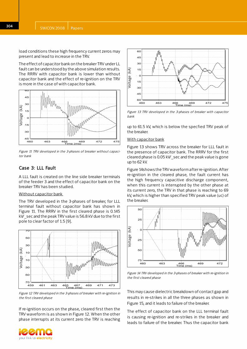
Figure 13 shows TRV across the breaker for LLL fault in the presence of capacitor bank. The RRRV for the first cleared phase is 0.05 kV/_sec and the peak value is gone up to 62 kV.
Figure 14shows the TRV waveform after re-ignition. After re-ignition in the cleared phase, the fault current has the high frequency capacitive discharge component, when this current is interrupted by the other phase at its current zero, the TRV in that phase is reaching to 69 kV, which is higher than specified TRV peak value (uc) of the breaker.
-60
-45
-30
-15
0
15
30
45
60
460 463 466 469 472 475
Electrotek Concepts® TOP, The Output Processor®
Voltage (kV)
Time (ms)
Volt
age
(kA
)
-75
-50
-25
0
25
50
460 463 466 469 472
Electrotek Concepts® TOP, The Output Processor®
Voltage (kV)
Time (ms)
Volt
age
(kA
)
Case 3: LLL Fault
A LLL fault is created on the line side breaker terminals of the feeder 3 and the effect of capacitor bank on the breaker TRV has been studied.
Without capacitor bank
The TRV developed in the 3-phases of breaker, for LLL terminal fault without capacitor bank has shown in Figure 11. The RRRV in the first cleared phase is 0.145 kV/_sec and the peak TRV value is 56.8 kV due to the first pole to clear factor of 1.5 [9].
Figure 11 TRV developed in the 3-phases of breaker without capaci-tor bank
Figure 12 TRV developed in the 3-phases of breaker with re-ignition in the first cleared phase
If re-ignition occurs on the phase, cleared first then the TRV waveform is as shown in Figure 12. When the other phase interrupts at its current zero the TRV is reaching
Figure 13 TRV developed in the 3-phases of breaker with capacitor bank
Figure 14 TRV developed in the 3-phases of breaker with re-ignition in the first cleared phase
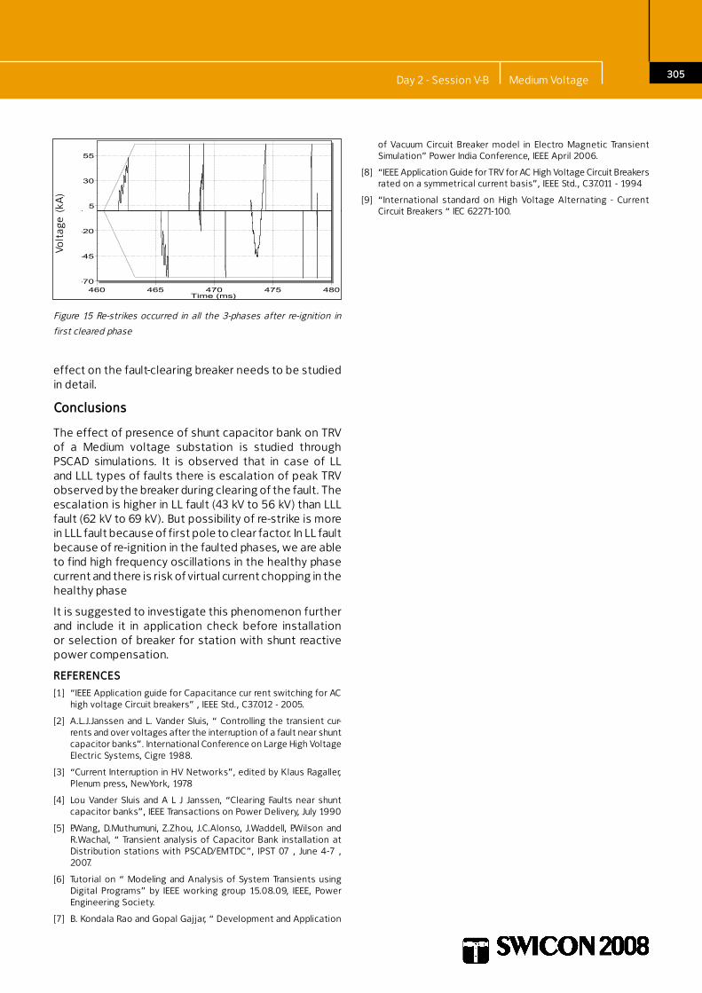
This may cause dielectric breakdown of contact gap and results in re-strikes in all the three phases as shown in Figure 15, and it leads to failure of the breaker.
The effect of capacitor bank on the LLL terminal fault is causing re-ignition and re-strikes in the breaker and leads to failure of the breaker. Thus the capacitor bank
SWICON 2008 Papers
305
effect on the fault-clearing breaker needs to be studied in detail.
Conclusions
The effect of presence of shunt capacitor bank on TRV of a Medium voltage substation is studied through PSCAD simulations. It is observed that in case of LL and LLL types of faults there is escalation of peak TRV observed by the breaker during clearing of the fault. The escalation is higher in LL fault (43 kV to 56 kV) than LLL fault (62 kV to 69 kV). But possibility of re-strike is more in LLL fault because of first pole to clear factor. In LL fault because of re-ignition in the faulted phases, we are able to find high frequency oscillations in the healthy phase current and there is risk of virtual current chopping in the healthy phase
It is suggested to investigate this phenomenon further and include it in application check before installation or selection of breaker for station with shunt reactive power compensation.
REFERENCES[1] “IEEE Application guide for Capacitance cur rent switching for AC
high voltage Circuit breakers” , IEEE Std., C37.012 - 2005.
[2] A.L.J.Janssen and L. Vander Sluis, “ Controlling the transient cur-rents and over voltages after the interruption of a fault near shunt capacitor banks”. International Conference on Large High Voltage Electric Systems, Cigre 1988.
[3] “Current Interruption in HV Networks”, edited by Klaus Ragaller, Plenum press, NewYork, 1978
[4] Lou Vander Sluis and A L J Janssen, “Clearing Faults near shunt capacitor banks”, IEEE Transactions on Power Delivery, July 1990
[5] P.Wang, D.Muthumuni, Z.Zhou, J.C.Alonso, J.Waddell, P.Wilson and R.Wachal, “ Transient analysis of Capacitor Bank installation at Distribution stations with PSCAD/EMTDC”, IPST 07 , June 4-7 , 2007.
[6] Tutorial on “ Modeling and Analysis of System Transients using Digital Programs” by IEEE working group 15.08.09, IEEE, Power Engineering Society.
[7] B. Kondala Rao and Gopal Gajjar, “ Development and Application
-70
-45
-20
5
30
55
460 465 470 475 480
Electrotek Concepts® TOP, The Output Processor®
Voltage (kV)
Time (ms)
Volt
age
(kA
)
Figure 15 Re-strikes occurred in all the 3-phases after re-ignition in
first cleared phase
of Vacuum Circuit Breaker model in Electro Magnetic Transient Simulation” Power India Conference, IEEE April 2006.
[8] “IEEE Application Guide for TRV for AC High Voltage Circuit Breakers rated on a symmetrical current basis”, IEEE Std., C37.011 - 1994
[9] “International standard on High Voltage Alternating - Current Circuit Breakers “ IEC 62271-100.
Day 2 - Session V-B Medium Voltage