Embed Size (px)
Citation preview
10th
International Conference on Contact Mechanics
CM2015, Colorado Springs, Colorado, USA
Study on Importance of Wheel-Rail Contact Modeling in Wheel Wear
Simulation
Gongquan Tao, Zefeng Wen, Xin Zhao, Xuesong Jin
State Key Laboratory of Traction Power, Southwest Jiaotong University, Chengdu 610031, China
*E-mail: [email protected]
ABSTRACT
This paper focuses on comparing three non-elliptic contact models, namely Kik-Piotrowski, STRIPES and
ANALYN, and the difference of wheel wear evaluated based on the three contact models. The three
non-elliptic contact models are compared in terms of normal contact solution and tangential contact
solution which is obtained by modifying Kalker’s simplified theory. In order to investigate the influence of
contact models on wheel wear, a wheel wear prediction model, including multi-body model of railway
vehicle, local contact analysis and wheel wear model based on USFD wear function, is developed. The
wear distributions over wheel profile under different operating conditions are analyzed. The results show
that the wear result based on elliptic approach has a relatively good agreement with CONTACT, which is a
surprising result. In all simulation cases, STRIPES and ANALYN predict nearly the same wheel wear and
both of them underestimate the wheel wear.
1. INTRODUCTION
The railway, as an eco-friendly and energy- efficient
mode of transportation, has attracted more and more
attentions in recent years. To meet the higher and
higher requirements of the modern railway,
especially of for the high speed and the heavy haul,
wear of the wheel-rail contact pair has to be
understood better in theory and well controlled in
practice. It has been well recognized by train
operators that a reliable prediction of wheel wear can
help to optimize the maintenance plan of wheelsets,
and the design of vehicles such as that of the
wheel/rail profiles and the suspension.
Complexity or uncertainty of the prediction of wheel
wear may come from simulation of the vehicle-track
dynamics, modeling of the wheel-rail rolling contact,
determination of the wear rate and other technic
details such as the smoothing and updating of the
profile after each cycle. The contact solutions
required in wear prediction include the size and
shape of the wheel-rail contact patch, normal and
tangential contact stresses, and the stick-slip
distinction in the contact patch. Sufficient accuracy is
required in the obtained results because errors can be
constantly accumulated in simulation, besides which
and the contact model embedded has to be should be
low in computational costs because the wheel-rail
rolling contact needs to be solved at every time step.
Rolling contact models developed with the boundary
element method, like Kalker’s CONTACT [1], or
with the finite element (FE) method are not suitable
due to their high computational costs, being
especially true for FE models. Analytical solution of
rolling contact, instead, is a more feasible choice, at
least for the current computational power. Today,
analytical solutions for non-elliptic contact derived
with the virtual penetration method have been
proposed by Linder [2], Kik-Piotrowski [3-4],
Ayasse-Chollet [5], Alonso-Giménez [6-7] and so on,
and that derived from the concept of approximate
surface deformation has also been proposed by
Sichani-Enblom-Berg [8]. In these models, tangential
problem for the non-elliptic contact is usually solved
with the modified FASTSIM of Kalker [9].
Sichani et al. [10] investigated the precision and
accuracy of non-elliptic contact models, including
Linder method [2], Kik-Piotrowski method [3-4] and
Ayasse-Chollet method (STRIPES) [5], these models
were implemented and compared in terms of contact
patch, as well as contact pressure and traction
distributions, and the CONTACT software was taken
as a reference. Besides, Sichani et al. [11]
investigated the difference between the new method,
named ANALYN [8], developed by themselves
recently and the approximate model of
Kik-Piotrowski and the results were evaluated using
CONTACT code. The research indicates ANALYN
to be more accurate in terms of contact patch and
stress distribution as well as creep force estimation.
Enblom and Berg [12] investigated the effect of the
elastic deformation contribution to the sliding
velocity on wheel wear. The rigid and elastic
methods employed in FASTSIM and CONTACT
code were compared, and it was indicated that a
reasonable agreement in wheel wear volume for pure
slip with large spin but a significant difference for
partial slip. Moreover, the influence of non-elliptic
contact modelling (STRIPES) on wheel wear rate
and profile shape also investigated by Enblom and
Berg [13].
The focus of this paper focuses on is to investigation
of the calculation accuracy and efficiency of
non-elliptic contact models, including
Kik-Piotrowski method [3-4], Ayasse-Chollet
method (STRIPES) [5] and Sichani-Enblom-Berg
method (ANALYN) [8], and the importance of
wheel-rail contact modeling in wheel wear
simulation. For comparison of normal solutions, i.e.,
of the shape and size of contact patch and the
pressure distribution, methods of those non-elliptic
models mentioned above and Hertz method are
chosen. Kalker’s CONTACT is taken as a reference.
Based on the normal solutions, Kalker’s simplify
theory (program FASTSIM) and the modified
FASTSIM for non-elliptic contact are employed to
solve the tangential contact problem. The obtained
tangent solutions such as the stick-slip distinction,
micro-slip distribution and the creep force are
compared with each other and with those of
CONTACT. Afterwards, the USFD wear function
[14] proposed by the University of Sheffield is
employed to calculate the wear, in which the local
wear rate is assumed to be determined by the energy
dissipation. It should be noted that the elastic
deformation that has a significant contribution to the
micro-slip distribution is considered in the present
work.
2. DESCRIPTION OF NON-ELLIPTIC
CONTACT
Hertz’s theory is widely used in railway dynamics
simulations for wheel-rail contact. However, the
Hertz solution is limited by some hypothesis, the
curvature within contact patch should be constant,
and the contact patch is assumed as an elliptic with
an elliptic contact pressure distribution. For
evaluation of the tangential properties FASTSIM
algorithm based on Kalker’s simplified theory is the
prevailing approach. However, the assumptions
adopted in Hertz’s theory are rarely meet, especially
for worn wheel and rail profiles.
To improve the contact modelling, several more or
less approximate alternative procedures have been
proposed in the past. The Kik-Piotrowski method [3],
STRIPES [5] and ANALYN [8] are investigated in
this paper.
2.1 Non-elliptic Contact Models
The Kik-Piotrowski method
Kik and Piotrowski [3] proposed a non-elliptic
contact model based on the concept of virtual
penetration (VP). The elastic deformation of both
contact bodies is neglected,, and based on the
assumption that the contact bodies can penetrate into
each other. In reality, the penetration does not occur
between the contacting bodies, while the deformation
occurs and the contact area is generated. On the basis
of some similarity of shapes of the contact area and
interpenetration region, the contact zone is
determined by the following assumption: the surfaces
of the bodies are virtually penetrated and the
resulting interpenetration region is taken as the area
of contact. Therefore, the interpenetration region will
be larger than the real contact area, and the
interpenetration region encloses real contact area. So
the rigid approach between the two bodies should be
reduced by a scaling factor, a constant number ε =
0.55 was adopted by Kik and Piotrowski. Besides, a
shape correction strategy is applied to the contact
patch, in which the shape ratio and area of the
contact patch remain the same as the interpenetration
area. As the same as the common assumption for the
methods based on the virtual penetration, the normal
pressure distribution in the direction of rolling is
assumed as the semi-elliptical. The Kik-Piotrowski
method is described in detail in ref. [3] and [4].
The Ayasse-Chollet method
The non-elliptic contact method developed by
Ayasse and Chollet (STRIPES) [5] also relies on the
interpenetration approach. In the STRIPES method, it
is possible to consider non-Hertzian conditions in
lateral direction, which means the lateral curvatures
within the contact area are not constant, while the
longitudinal curvatures remain constant as in the
Hertzian assumptions.
The correction strategy in STRIPES is different from
Kik-Piotrowski method, Ayasse and Chollet
proposed that the contact patch in the geometric
problem as well as in the Hertz problem should have
the same characteristics, in the other words, the shape
ratio of the geometric ellipse and the contact ellipse
should be the same, and the semi-axes of the
geometric ellipse and the contact ellipse also should
be the same. To meet these, curvatures and rigid
approach in geometric problem should be corrected.
In ref. [5], three correction strategies were proposed:
(1) compensating the longitudinal curvature only and
smoothing of lateral curvature; (2) compensating
lateral curvature; (3) compensating both longitudinal
and lateral curvature. In this article, the last one is
used, both relative curvatures Ai and Bi in each
longitudinal stripes are supposed to be corrected. The
detailed descriptions of STRIPES method can be
seen in ref. [5] and [15].
The Sichani-Enblom-Berg method
Unlike the VP-based methods, Sichani, Enblom and
Berg [8] developed a novel method (ANALYN) to
solve the normal contact problem in the wheel-rail
interface. The surfaces deformation of wheel and rail
is estimated using the separation between them,
instead of being neglected, and there is no correction
of relative curvatures or rigid approach, it is named
the approximate surface deformation (ASD) method.
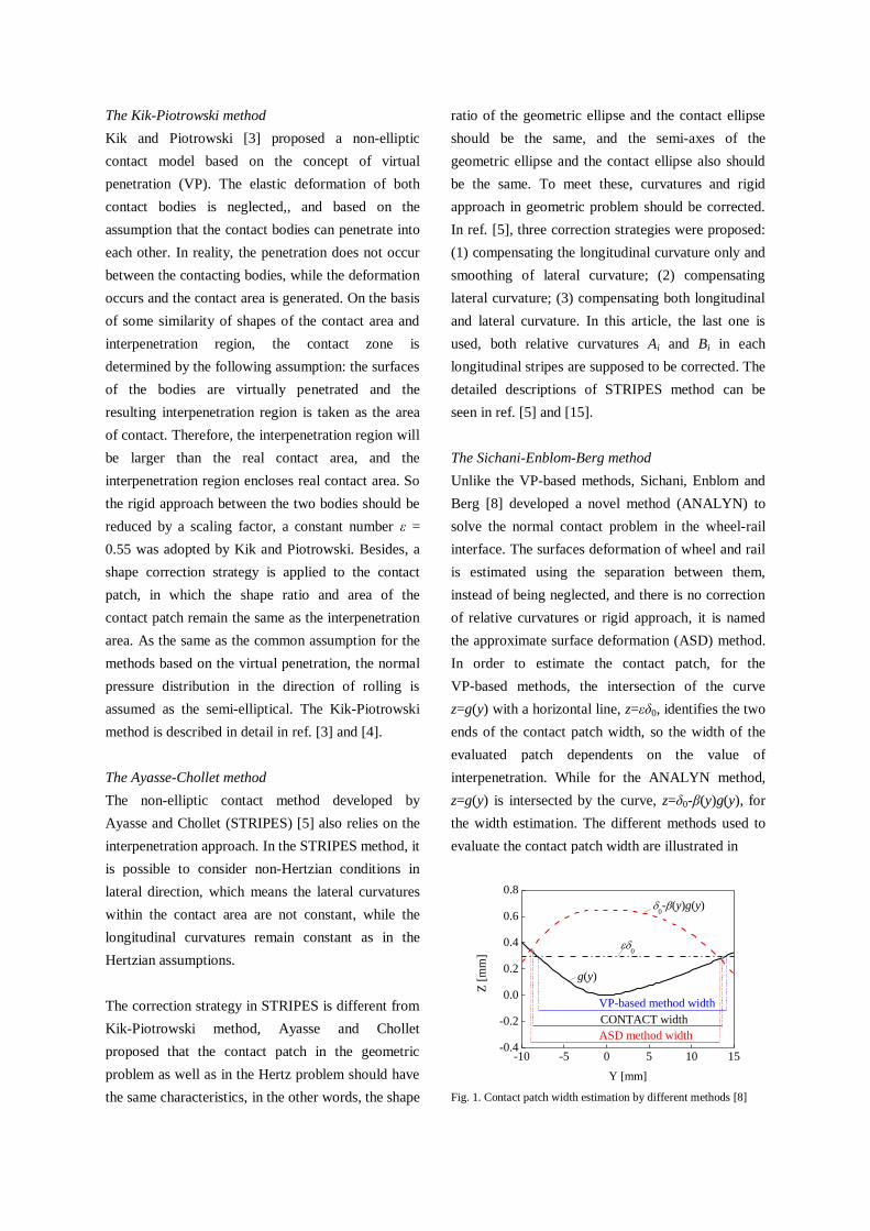
In order to estimate the contact patch, for the
VP-based methods, the intersection of the curve
z=g(y) with a horizontal line, z=εδ0, identifies the two
ends of the contact patch width, so the width of the
evaluated patch dependents on the value of
interpenetration. While for the ANALYN method,
z=g(y) is intersected by the curve, z=δ0-β(y)g(y), for
the width estimation. The different methods used to
evaluate the contact patch width are illustrated in
-10 -5 0 5 10 15-0.4
-0.2
0.0
0.2
0.4
0.6
0.8
ASD method width
CONTACT width
Z [
mm
]
Y [mm]
VP-based method width
g(y)
0-(y)g(y)
0
Fig. 1. Contact patch width estimation by different methods [8]
Figure 1. The detailed descriptions of ANALYN
method can be seen in ref. [8].
The common assumption for the VP-based methods
and ASD method is the semi-elliptical normal stress
distribution in the direction of rolling, while it is
non-elliptical in the lateral direction.
2.2 The Solution of Tangential Contact Problem
The FASTSIM algorithm, based on Kalker’s
simplified theory [9], is the most widely used for
solving the tangential wheel-rail contact problem,
because of its perfect efficiency and accuracy.
Moreover, it can obtain not only the creep force but
also the tractions and the micro-slip distribution.
However, the original FASTSIM is developed for
elliptic contact patches, in order to adapt FASTSIM
to non-elliptic patches the flexibility parameters
should be re-calculated.
Piotrowski and Kik [4] proposed an equivalent
ellipse method to calculate the flexibility parameters.
An equivalent ellipse is defined for each separate
contact region by setting the ellipse area equal to the
non-elliptic contact area and ellipse semi-axes ratio
equal to length-to-width ratio of the patch.
A local ellipse method is used by Ayasse and Chollet
[5] to calculate the flexibility parameters. The contact
patch should be divided into several independent
longitudinal stripes, then, a virtual local ellipse can
be assigned to each strip, the flexibility parameters
can be calculated using the local ellipses. The local
ellipses are determined by employing relative
curvatures at the center of each strip in Hertz solution.
ANALYN has the same form as STRIPES for the
tangential solution.
It should be noted the contact patch is assumed to be
planar, and the spin value is constant across the patch
and calculated using the contact angle at the
geometry contact point in Kik-Piotrowski method,
however, in STRIPES and ANALYN, each strip has
a different contact angle,,which causes different spin
value.
3. RESULTS AND DISCUSSION OF
WHEEL-RAIL CONTACT
In order to compare the difference among the
Kik-Piotrowski method [3], STRIPES [5] and
ANALYN [8], Kalker’s program CONTACT [1]
is used as a reference. In addition, the results are
also compared with Hertz solution. The tangential
contact of the non-elliptic models is then solved by
using the FASTSIM algorithm [9], which is
modified to be available for the non-elliptic
patches.
The non-elliptic patch is formed by the contact
between a wheel with standard profile LM and a
rail of standard profile CHN60 with the inclination
of 1:40. Both wheel and rail are assumed to have
the same material properties with ν = 0.28 and E =
206 GPa. The back-to-back distance of wheelset is
1353 mm with a mean rolling circle radius of 420
mm, and the gauge is 1435 mm. The axle load is
14 ton. Several contact cases with different
wheelset displacements are investigated. The
contact patch, contact pressure, and micro-slip
distribution and traction distributions are
compared.
3.1 The results of normal contact
Taking a wheelset lateral displacement of Δy = 3
mm as an example, which is a typical example of a
non-elliptic tread contact, the lateral relative
curvature within contact area is not a constant, As
shown in Figure 2,it is composed of a piecewise
function, and is not continuity.
Figure 3 shows the contact patch and maximum
pressure predicted by the three non-elliptic contact
models and they are compared with the results of
CONTACT and Hertz solution. From Fig.3 it can
be seen that all three non-elliptic methods predict a
non-elliptic patch with relatively good agreement
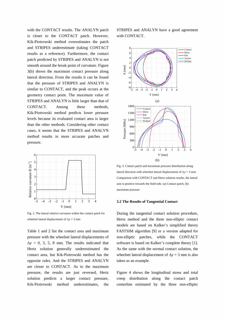
with the CONTACT results. The ANALYN patch
is closer to the CONTACT patch. However,
Kik-Piotrowski method overestimates the patch
and STRIPES underestimate (taking CONTACT
results as a reference). Furthermore, the contact
patch predicted by STRIPES and ANALYN is not
smooth around the break point of curvature. Figure
3(b) shows the maximum contact pressure along
lateral direction. From the results it can be found
that the pressure of STRIPES and ANALYN is
similar to CONTACT, and the peak occurs at the
geometry contact point. The maximum value of
STRIPES and ANALYN is little larger than that of
CONTACT. Among these methods,
Kik-Piotrowski method predicts lower pressure
levels because its evaluated contact area is larger
than the other methods. Considering other contact
cases, it seems that the STRIPES and ANALYN
method results in more accurate patches and
pressure.
-5 -4 -3 -2 -1 0 1 2 3 40
1
2
3
4
5
6
Rel
ativ
e cu
rvat
ure
B [
m-1
]
Y [mm]
Fig. 2. The lateral relative curvature within the contact patch for
wheelset lateral displacement of Δy = 3 mm
Table 1 and 2 list the contact area and maximum
pressure with the wheelset lateral displacements of
Δy = 0, 3, 5, 8 mm. The results indicated that
Hertz solution generally underestimated the
contact area, but Kik-Piotrowski method has the
opposite rules. And the STRIPES and ANALYN
are closer to CONTACT. As to the maximum
pressure, the results are just reversed, Hertz
solution predicts a larger contact pressure,
Kik-Piotrowski method underestimates, the
STRIPES and ANALYN have a good agreement
with CONTACT.
-5 -4 -3 -2 -1 0 1 2 3 4-8
-6
-4
-2
0
2
4
6
8
X [
mm
]
Y [mm]
Contact
Hertz
Kik
Ayasse
Sichani
(a)
-5 -4 -3 -2 -1 0 1 2 3 40
300
600
900
1200
1500
1800
Pre
ssu
re [
MP
a]
Y [mm]
Contact
Hertz
Kik
Ayasse
Sichani
(b)
Fig. 3. Contact patch and maximum pressure distribution along
lateral direction with wheelset lateral displacement of Δy = 3 mm.
Comparison with CONTACT and Hertz solution results, the lateral
axis is positive towards the field side. (a) Contact patch, (b)
maximum pressure
3.2 The Results of Tangential Contact
During the tangential contact solution procedure,
Hertz method and the three non-elliptic contact
models are based on Kalker’s simplified theory
FASTSIM algorithm [9] or a version adapted for
non-elliptic patches, while the CONTACT
software is based on Kalker’s complete theory [1].
As the same with the normal contact solution, the
wheelset lateral displacement of Δy = 3 mm is also
taken as an example.
Figure 4 shows the longitudinal stress and total
creep distribution along the contact patch
centerline estimated by the three non-elliptic

contact models, and they are compared with the
CONTACT and Hertz+FASTSIM results. It
should be kept in mind that the normal pressure in
FASTSIM has a parabolic distribution rather than
semi-elliptic. The contact patch is partial slip (see
Figure 5) at this contact case.The FASTSIM-based
approach for calculation of tractions results in
almost the same tangential stress distribution along
the rolling direction. This is because the tangential
stress increases linearly in the adhesion area until
it saturates and follows a parabolic traction bound
curve in the slip area when FASTSIM is used. It
also indicates a larger slope in the patch. However,
the stress is non-linear in the adhesion area for
CONTACT solution. The characteristic of
tractions obtained in this paper is similar to
Enblom’s [12]. Figure 4(b) shows the total creep
magnitude distribution along the contact patch
centerline for partial slip, and the elastic
deformation contribution to the creep is taken into
account. In this case the total creep achieved by
the FASTSIM-based approach is generally larger
than CONTACT, and the total creep distribution
calculated by Hertz+FASTSIM, Ayasse+
FASTSIM and Sichani+FASTSIM is almost the
same and the value is also larger than other
approaches.
The stick-slip distribution within the contact patch
predicted by different models is illustrated in
Figure 5. In the pictures, the blank area stands for
adhesion region and arrows area is micro-slip
region, and the direction of arrows indicates the
slip direction of the particles within micro-slip
region, and the length of the arrows means the
relative magnitude of the creep. As shown in Fig.5,
the contact patch is partial slip, only the trail area
of the contact patch is in micro-slip state. The
stick-slip distribution and the slip direction of the
particles within micro-slip region between all
methods almost have no difference.
-8 -6 -4 -2 0 2 4 6 80
50
100
150
200
250
300
Lo
ng
itu
din
al s
tres
s [M
Pa]
X [mm]
CONTACT
Hertz+FASTSIM
Kik+FASTSIM
Ayasse+FASTSIM
Sichani+FASTSIM
(a)
-8 -6 -4 -2 0 2 4 6 8
0.0
0.2
0.4
0.6
0.8
1.0
To
tal
cree
p [
%]
X [mm]
CONTACT
Hertz+FASTSIM
Kik+FASTSIM
Ayasse+FASTSIM
Sichani+FASTSIM
(b)
Fig. 4. Longitudinal stress and total creep distribution along the
contact patch centerline with wheelset lateral displacement of Δy =
3 mm. The creepages are obtained dependent on the results of the
relationship of contact geometry (the yaw angle of wheelset is
unconsidered) and ξx = -0.07%, ξy = 0, ξη= -0.195 [1/m]. (a)
Longitudinal stress, (b) total creep
Table 1. Contact area comparison between different models (mm2)
Wheelset displacement (mm) CONTACT Hertz Kik Ayasse Sichini
0 67.2 60.5 75.1 63.8 58.9
3 75.1 60.4 85.9 68.2 72.4
5 103.9 102.6 109.9 100.6 100.0
8 41.5 26.5 62.6 31.8 48.4

Table 2. Maximum pressure comparison between different models (MPa)
Wheelset displacement (mm) CONTACT Hertz Kik Ayasse Sichini
0 1689 1697 1399 1754 1696
3 1580 1697 1233 1753 1694
5 1007 989 924 989 989
8 3296 3738 1675 3779 3732
-8 -6 -4 -2 0 2 4 6 8-6
-4
-2
0
2
4
CONTACT
Y [
mm
]
X [mm]
-8 -6 -4 -2 0 2 4 6 8-6
-4
-2
0
2
4
Hertz+FASTSIM
Y [
mm
]X [mm]
(a) (b)
-8 -6 -4 -2 0 2 4 6 8-6
-4
-2
0
2
4
Kik+FASTSIM
Y [
mm
]
X [mm]
-8 -6 -4 -2 0 2 4 6 8-6
-4
-2
0
2
4
Ayasse+FASTSIM
Y [
mm
]
X [mm]
-8 -6 -4 -2 0 2 4 6 8-6
-4
-2
0
2
4
Sichani+FASTSIM
Y [
mm
]
X [mm]
(c) (d) (e)
Fig. 5. Stick-slip distribution for Δy = 3 mm predicted by (a) CONTACT, (b) Hertz+FASTSIM, (c) Kik+FASTSIM, (d) STRIPES+
FASTSIM, (e) ANALYN+FASTSIM, with ξx = -0.07%, ξy = 0, ξη= -0.195 [1/m]
4. WHEEL WEAR PREDICTION MODEL
Wheel wear prediction is a very complicated
process and it is an across-disciplines. A general
architecture of the wheel wear prediction model is
shown in Fig. 6, and is consisted of four main
modules: (1) multi-body simulation of railway
vehicle-track dynamics; (2) local contact model; (3)
wear calculation; (4) smoothing and updating of
the wheel profile.
The wheel wear prediction starts from the vehicle
and track dynamic simulation which is done using
commercial software SIMPACK. At each
integration step of the vehicle-track dynamic
simulation, global contact parameters (position
and dimensions of the various active contacts,
normal force, wheelset lateral displacement, yaw
angle and creepages) are output and used to
perform the local contact analysis, the tractions
and creep distribution within contact patch are
achieved. Then the wear function developed by
USFD [14], related the energy dissipated in the
wheel-rail contact patch with the amount of worn
material to be removed from the contact surface, is
used to evaluate wheel wear. At last the wear
distribution and worn profile are smoothed, then
the worn profile is input into the next wear step.
The local contact model is described in the Section
2, so only the multi-body model of vehicle-track
and wear model are introduced in this section.

Fig. 6. General architecture of the wheel wear prediction model
4.1 Multi-Body Model of Railway Vehicle
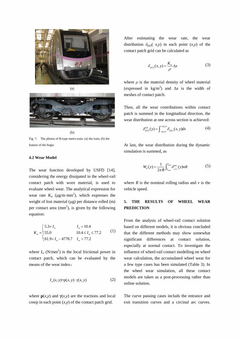
The B-type metro train (see Fig. 7(a)) running on
Beijing Changping metro line is modeled in this
paper, which composed of four powered coaches
in the middle and two trailer coaches at external,
but only a trailer coach has been performed in
present research activity. The vehicle model
consists of a coach and two bogies with two
wheelsets, the axle-box is also considered in this
model. The vehicle model developed in this paper
is provided with two stages of suspensions (see
Fig. 7(b)). The primary suspensions are made up
of coaxial spring and nonlinear vertical damper,
which link the axle boxes with the bogie frame.
Because the maximum oprational speed of this
vehicle is 120 km/h, for the running stability
against the hunting at high speed in straight track
requires primary suspensions have higher
longitudinal stiffness, a longitudinal linking arm is
equipped which connects the axle box with the
frame and provides a higher longitudinal stiffness.
The secondary suspension stage, connecting the
bogie frame with the car body, comprises the
following elements: two air-springs for
longitudinal, lateral and vertical stiffness; a
nonlinear traction rod, to transmit the traction or
braking efforts; nonlinear lateral bump stops;
nonlinear lateral dampers. All the linking elements
of primary and secondary suspensions are modeled
as viscoelastic force elements, taking into account
all the mechanical nonlinearities (vertical dampers
of primary suspensions, traction rod, lateral bump
stops and lateral dampers of secondary
suspensions). The resultant whole SIMPACK
multibody model includes 15 rigid bodies: 1 coach,
2 bogie frames, 4 wheelsets and 8 axle boxes.
The flexibility of the track is neglected in present
model, the rail profile is 60 kg/m in China
(CHN60), the gauge is 1435 mm, wheel nominal
rolling radius is 420 mm, wheelset back-to-back
distance is 1353 mm. The FASTSIM based on
Kalker’s simplified theory [9] is used to solve the
wheel and rail contact. The coefficient of friction
is set to 0.3 and track irregularity of AAR6 is
considered.
P,yw, ψ, j
Normal contact solution
New profiles
Wheel wear calculation Accumulated wear depth
USFD wear function
Local contact model
Hertz, Kik, Ayasse,
Sichani, CONTACT
P3j, a, b
Tangential contact solution
FASTSIM, CONTACT
Ptj, γj
Lo
cal co
nta
ct mo
del
Multi-body model (SIMPACK)
(a)
(b)
Fig. 7. The photos of B-type metro train. (a) the train, (b) the
feature of the bogie
4.2 Wear Model
The wear function developed by USFD [14],
considering the energy dissipated in the wheel-rail
contact patch with worn material, is used to
evaluate wheel wear. The analytical expression for
wear rate Kw (μg/m·mm2), which expresses the
weight of lost material (μg) per distance rolled (m)
per contact area (mm2), is given by the following
equation:
5.3 10.4
55.0 10.4 77.2
61.9 4778.7 77.2
w w
w w
w w
I I
K I
I I
(1)
where Iw (N/mm2) is the local frictional power in
contact patch, which can be evaluated by the
means of the wear index:
( , )=p( , ) γ( , )wI x y x y x y (2)
where p(x,y) and γ(x,y) are the tractions and local
creep in each point (x,y) of the contact patch grid.
After estimating the wear rate, the wear
distribution δp(t)( x,y) in each point (x,y) of the
contact patch grid can be calculated as
( ) ( , ) wp t
Kx y x
(3)
where ρ is the material density of wheel material
(expressed in kg/m3) and Δx is the width of
meshes of contact patch.
Then, all the wear contributions within contact
patch is summed in the longitudinal direction, the
wear distribution at one across section is achieved:
( )
( ) ( )( )
( ) ( , )a y
tot
p t p ta y
y x y dx
(4)
At last, the wear distribution during the dynamic
simulation is summed, as
( )
1( ) ( )
2
end
p tstart
Ttot
dT
W y y vdtR
(5)
where R is the nominal rolling radius and v is the
vehicle speed.
5. THE RESULTS OF WHEEL WEAR
PREDICTION
From the analysis of wheel-rail contact solution
based on different models, it is obvious concluded
that the different methods may show somewhat
significant differences at contact solution,
especially at normal contact. To investigate the
influence of wheel-rail contact modelling on wheel
wear calculation, the accumulated wheel wear for
a few type cases has been simulated (Table 3). In
the wheel wear simulation, all these contact
models are taken as a post-processing rather than
online solution.
The curve passing cases includs the entrance and
exit transition curves and a circinal arc curves.
Equal amount of right-hand and left-hand curves
as well as forward-backward symmetry is
assumed.
Table 3. The wheel wear simulation cases
Case Radius (m) Cant (mm) Speed (km·h-1)
Tangent ∞ 0 90
R400 400 120 60
R600 600 120 80
R1000 1000 76 80
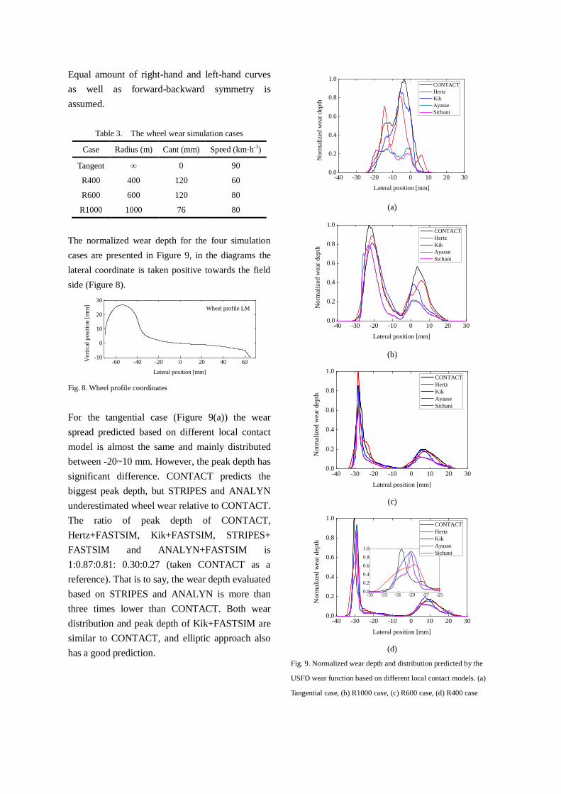
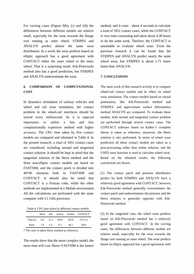
The normalized wear depth for the four simulation
cases are presented in Figure 9, in the diagrams the
lateral coordinate is taken positive towards the field
side (Figure 8).
-60 -40 -20 0 20 40 60-10
0
10
20
30
Ver
tica
l p
osi
tio
n [
mm
]
Lateral position [mm]
Wheel profile LM
Fig. 8. Wheel profile coordinates
For the tangential case (Figure 9(a)) the wear
spread predicted based on different local contact
model is almost the same and mainly distributed
between -20~10 mm. However, the peak depth has
significant difference. CONTACT predicts the
biggest peak depth, but STRIPES and ANALYN
underestimated wheel wear relative to CONTACT.
The ratio of peak depth of CONTACT,
Hertz+FASTSIM, Kik+FASTSIM, STRIPES+
FASTSIM and ANALYN+FASTSIM is
1:0.87:0.81: 0.30:0.27 (taken CONTACT as a
reference). That is to say, the wear depth evaluated
based on STRIPES and ANALYN is more than
three times lower than CONTACT. Both wear
distribution and peak depth of Kik+FASTSIM are
similar to CONTACT, and elliptic approach also
has a good prediction.
-40 -30 -20 -10 0 10 20 300.0
0.2
0.4
0.6
0.8
1.0
No
rmal
ized
wea
r d
epth
Lateral position [mm]
CONTACT
Hertz
Kik
Ayasse
Sichani
(a)
-40 -30 -20 -10 0 10 20 300.0
0.2
0.4
0.6
0.8
1.0
Norm
aliz
ed w
ear
dep
th
Lateral position [mm]
CONTACT
Hertz
Kik
Ayasse
Sichani
(b)
-40 -30 -20 -10 0 10 20 300.0
0.2
0.4
0.6
0.8
1.0
No
rmal
ized
wea
r d
epth
Lateral position [mm]
CONTACT
Hertz
Kik
Ayasse
Sichani
(c)
-40 -30 -20 -10 0 10 20 300.0
0.2
0.4
0.6
0.8
1.0
-35 -33 -31 -29 -27 -250.0
0.2
0.4
0.6
0.8
1.0
No
rmal
ized
wea
r d
epth
Lateral position [mm]
CONTACT
Hertz
Kik
Ayasse
Sichani
(d)
Fig. 9. Normalized wear depth and distribution predicted by the
USFD wear function based on different local contact models. (a)
Tangential case, (b) R1000 case, (c) R600 case, (d) R400 case
For curving cases (Figure 9(b), (c) and (d)) the
differences between different models are relative
small, especially for the wear towards the flange
root running as outer wheel. STRIPES and
ANALYN predict almost the same wear
distribution. In a word, the wear predicts based on
elliptic approach has a good agreement with
CONTACT either the outer wheel or the inner
wheel. That is a surprising result. Kik-Piotrowski
method also has a good prediction, but STRIPES
and ANALYN underestimate the wear.
6. COMPARISON OF COMPUTATIONAL
COST
In dynamics simulation of railway vehicles and
wheel and rail wear simulation, the contact
problem in the wheel-rail interfaces should be
solved every millisecond. So it is especial
importance to utilize a fast and less
computationally expensive method with higher
accuracy. The CPU time taken by five contact
models are compared and tabulated in Table 4. In
the present research, a total of 1851 contact cases
are considered, including normal and tangential
contact solution. It should be kept in mind that the
tangential solution of the Hertz method and the
three non-elliptic contact models are based on
FASTSIM, and the contact patch is divided into
40*40 elements both in FASTSIM and
CONTACT. It should also be noted that
CONTACT is a Fortran code, while the other
methods are implemented in e Matlab environment.
All the calculations are performed with the same
computer with 3.1 GHz processor.
Table 4. CPU time taken by different contact models
Hertz Kik Ayasse Sichani CONTACT
Time (s) 4.0 25.3 108.4 185.8 15772.5
Ratio 1.0 6.3 27.1 46.5 3943
* The ratio is taken Hertz method as reference.
The results show that the more complex model, the
more time will cost. Hertz+FASTSIM is the fastest
method, and it costs about 4 seconds to calculate
a total of 1851 contact cases, while the CONTACT
is very time consuming and taken about 4.38 hours
to do the same work. Therfore, the CONTACT is
unsuitable to evaluate wheel wear. From the
previous research it can be found that the
STRIPES and ANALYN predict nearly the same
wheel wear, but STRIPES is about 1.71 times
faster than ANALYN.
7. CONCLUSIONS
The main work of this research activity is to compare
wheel-rail contact models and its effect on wheel
wear simulation. The contact models based on virtual
penetration, like Kik-Piotrowski method and
STRIPES, and approximate surface deformation
method ANALYN are compared. To evaluate these
models, both normal and tangential contact problem
are performed through several contact cases. The
CONTACT software based on Kalker’s complete
theory is taken as reference, moreover, the Hertz
solution is also performed. In terms of wheel wear
prediction all these contact models are taken as a
post-processing rather than online solution, and the
USFD wear function is used to calculate wheel wear.
Based on the obtained results, the following
conclusions are drawn.
(1) The contact patch and pressure distribution
predict by both STRIPES and ANALYN have a
relatively good agreement with CONTACT, however,
Kik-Piotrowski method generally overestimates the
contact patch and underestimates the pressure and the
Hertz solution is generally opposite with Kik-
Piotrowski method.
(2) In the tangential case, the wheel wear predicts
based on Kik-Piotrowski method has a relatively
good agreement with CONTACT. In the curving
cases, the differences between different models are
relative small, especially for the wear towards the
flange root running as outer wheel. The wear predicts
based on elliptic approach has a good agreement with
CONTACT either the outer wheel or the inner wheel,
this is a surprising result. In all simulation cases,
STRIPES and ANALYN evaluate nearly the same
wheel wear and both of them underestimate the
wheel wear.
(3) The computational cost between these contact
models has a significant difference. The ratio of time
cost between Hertz, Kik-Piotrowski, STRIPES,
ANALYN methods and CONTACT is
1:6.3:27.1:46.5: 3934. The CONTACT is the most
time consuming method and unsuitable for wheel
wear.
8. ACKNOWLEDGMENTS
The present work is supported by the National
Natural Science Foundation of China (Nos.
U1134202, 51275427 and 51275430).
9. REFERENCES
1 J. J. Kalker, Three-Dimensional Elastic Bodies
in Rolling Contact, Kluwer Academic
Publishers, Dordrecht, 1990. 2 C.Linder, Verschleiss von Eisenbahnrädern mit
Unrundheiten (Ph.D. thesis), ETH Nr. 12342,
1997. 3 W. Kik, and J. Piotrowski, A fast, approximate
method to calculate normal load at contact
between wheel and rail and creep forces during
rolling. In: I. Zobory (Ed), Proceedings of the
Second Mini Conference on Contact Mechanics
and Wear of Rail/Wheel Systems. Budapest,
Hungary, 1996. 4 J. Piotrowski, W.Kik, A simplified model of
wheel/rail contact mechanics for non-Hertzian
problems and its application in rail vehicle
dynamic simulations, Vehicle Systems
Dynamics, 46(1–2) (2008) 27–48. 5 J. Ayasse, H. Chollet, Determination of the
wheel rail contact patch in semi-Hertzian
conditions, Vehicle Systems Dynamics, 43(3)
(2005) 161–172.
6 A. Alonso, J. G. Giménez, A new method for the
solution of the normal contact problem in the
dynamic simulation of railway vehicles, V
Vehicle Systems Dynamics, 43(2) (2005)
149-160. 7 A. Alonso, J. G. Giménez, Some new
contributions to the resolution of the normal
wheel-rail contact problem, Vehicle Systems
Dynamics, 44(Suppl.) (2006) 230-239. 8 M. Sh. Sichani, R. Enblom, M. Berg, A novel
method to model wheel-rail normal contact in
vehicle dynamics simulation, Vehicle Systems
Dynamics, 52(12) (2014) 1752-1764. 9 J. J. Kalker, A fast algorithm for the simplified
theory of rolling contact, Vehicle Systems
Dynamics, 11 (1982) 1-13. 10 M. Sh. Sichani, R. Enblom, M. Berg,
Comparison of non-elliptic contact models:
towards fast and accurate modelling of
wheel-rail contact, Wear, 314 (2014) 111-117. 11 M. Sh. Sichani, R. Enblom, M. Berg, A fast
non-elliptic contact model for application to rail
vehicle dynamics simulation, Proceedings of
the Second International Conference on
Railway Technology: Research, Development
and Maintenance, Civil-Comp Press,
Stirlingshire, UK, Paper 266, 2014. 12 R. Enblom, M. Berg, Simulation of railway
wheel profile development due to wear —
influence of disc braking and contact
environment, Wear, 258 (2005) 1055-1063. 13 R. Enblom, M. Berg, Impact of non-elliptic
contact modelling in wheel wear simulation,
Wear, 265 (2008) 1532-1541. 14 F. Braghin, R. Lewis, R. S. Dwyer-Joyce, S.
Bruni, A mathematical model to predict railway
wheel profile evolution due to wear, Wear, 261
(2006) 1253-1264. 15 X. Quost, M. Sebes, A. Eddhahak, J. Ayasse, H.
Chollet, P. Gautier, F. Thouverez, Assessment
of a semi-Hertzian method for determination of
wheel-rail contact patch, Vehichle Systems
Dynamics, 44(10) (2006) 789-814.


![[CM2015] Chapter 9 - Land Ice Modeling](https://img.pdfslide.net/doc/110x75/587476e91a28ab4a758b6bab/cm2015-chapter-9-land-ice-modeling.jpg)
![[CM2015] Chapter 6 - Land Surface Process Modeling](https://img.pdfslide.net/doc/110x75/589f959c1a28ab1b198b6269/cm2015-chapter-6-land-surface-process-modeling.jpg)
![[CM2015] Chapter 7 - Biogeochemistry](https://img.pdfslide.net/doc/110x75/589f959c1a28ab1b198b6265/cm2015-chapter-7-biogeochemistry.jpg)
![[CM2015] Chapter 1 - Climate System](https://img.pdfslide.net/doc/110x75/5879e9fc1a28ab15288b67b9/cm2015-chapter-1-climate-system.jpg)
![[CM2015] Chapter 3 - AGCM](https://img.pdfslide.net/doc/110x75/589f95751a28ab1b198b6213/cm2015-chapter-3-agcm.jpg)

![[CM2015] Chapter 10 - Coupling Techniques](https://img.pdfslide.net/doc/110x75/5877aaa91a28ab826e8b6c83/cm2015-chapter-10-coupling-techniques.jpg)