Embed Size (px)
Citation preview
SUSPENSION BRIDGESUSPENSION BRIDGE SUSPENSION BRIDGESUSPENSION BRIDGE
SUSPENSION BRIDGE
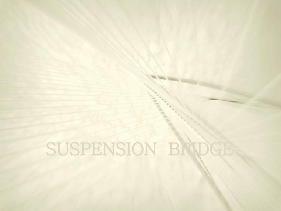
FOUR BASIC TYPES OF BRIDGES (ON THE BASIS OF LOAD TRANSFER)
BEAM BRIDGE The beam type is the simplest type of bridge. The beam bridge could be anything as simple as a plank of wood to a complex structure. It is made of two or more supports which hold up a beam.
ARCH BRIDGE In the arch type of bridge, weight is carried outward along two paths, curving toward the ground.
CANTILEVER BRIDGE In the cantilever type of bridge, two beams support another beam, which is where the deck or traffic way is.
TYPICAL SUSPENSION BRIDGE The deck (trafficway) of a suspension bridge is hung by suspender cables which hang from master cables (resting on the towers). The cables transfer the weight to the towers, which transfer the weight to the ground
CABLE STAYED BRIDGE Cable-stayed bridges have towers, but cables from the towers go directly to the road deck, instead of spanning from tower to tower.
SUSPENSION BRIDGES
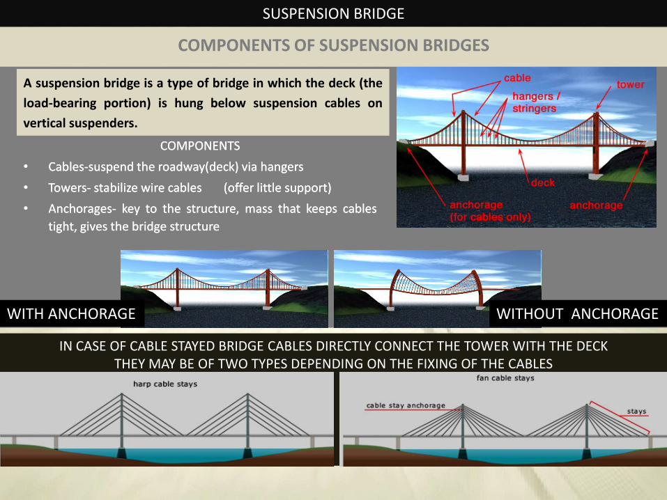
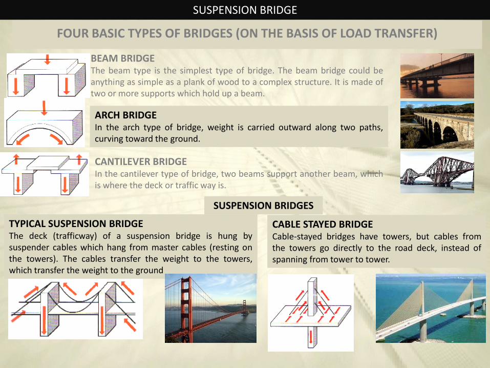
IN CASE OF CABLE STAYED BRIDGE CABLES DIRECTLY CONNECT THE TOWER WITH THE DECK THEY MAY BE OF TWO TYPES DEPENDING ON THE FIXING OF THE CABLES
A suspension bridge is a type of bridge in which the deck (the
load-bearing portion) is hung below suspension cables on
vertical suspenders.
WITH ANCHORAGE WITHOUT ANCHORAGE
SUSPENSION BRIDGE
COMPONENTSCOMPONENTS
•• CablesCables--suspendsuspend thethe roadway(deck)roadway(deck) viavia hangershangers
•• TowersTowers-- stabilizestabilize wirewire cablescables (offer(offer littlelittle support)support)
•• AnchoragesAnchorages-- keykey toto thethe structure,structure, massmass thatthat keepskeeps cablescables
tight,tight, givesgives thethe bridgebridge structurestructure
COMPONENTS OF SUSPENSION BRIDGES
SUSPENSION BRIDGE
EVOLUTION OF SUSPENSION BRIDGES
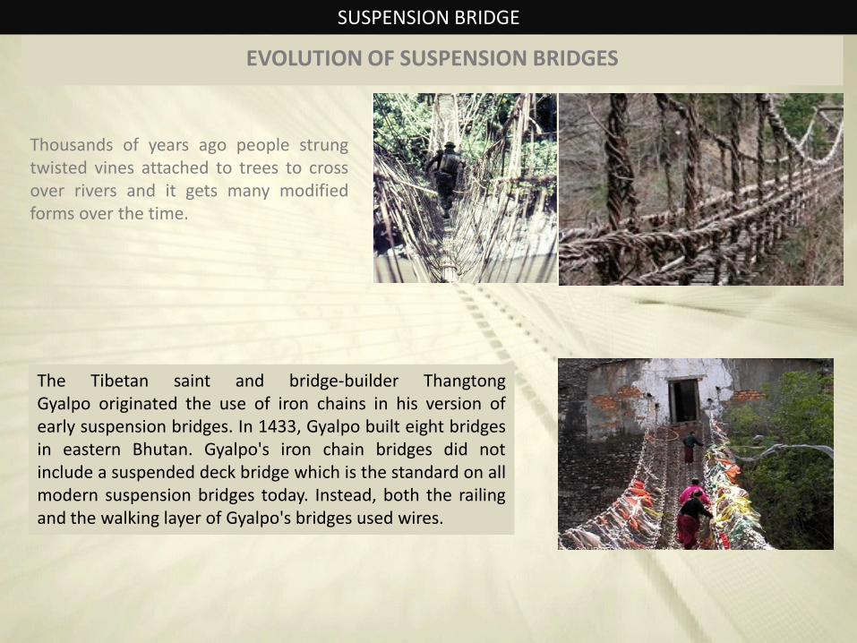
Thousands of years ago people strung twisted vines attached to trees to cross over rivers and it gets many modified forms over the time.
The Tibetan saint and bridge-builder Thangtong Gyalpo originated the use of iron chains in his version of early suspension bridges. In 1433, Gyalpo built eight bridges in eastern Bhutan. Gyalpo's iron chain bridges did not include a suspended deck bridge which is the standard on all modern suspension bridges today. Instead, both the railing and the walking layer of Gyalpo's bridges used wires.
SUSPENSION BRIDGE
EVOLUTION OF SUSPENSION BRIDGES
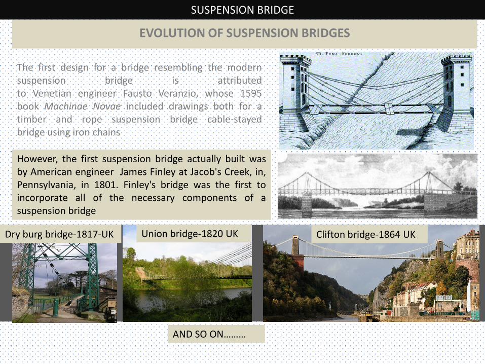
The first design for a bridge resembling the modern suspension bridge is attributed to Venetian engineer Fausto Veranzio, whose 1595 book Machinae Novae included drawings both for a timber and rope suspension bridge cable-stayed bridge using iron chains
However, the first suspension bridge actually built was by American engineer James Finley at Jacob's Creek, in, Pennsylvania, in 1801. Finley's bridge was the first to incorporate all of the necessary components of a suspension bridge
Dry burg bridge-1817-UK Union bridge-1820 UK Clifton bridge-1864 UK
AND SO ON………
SUSPENSION BRIDGE
STRUCTURAL ANALYSIS - LOADS
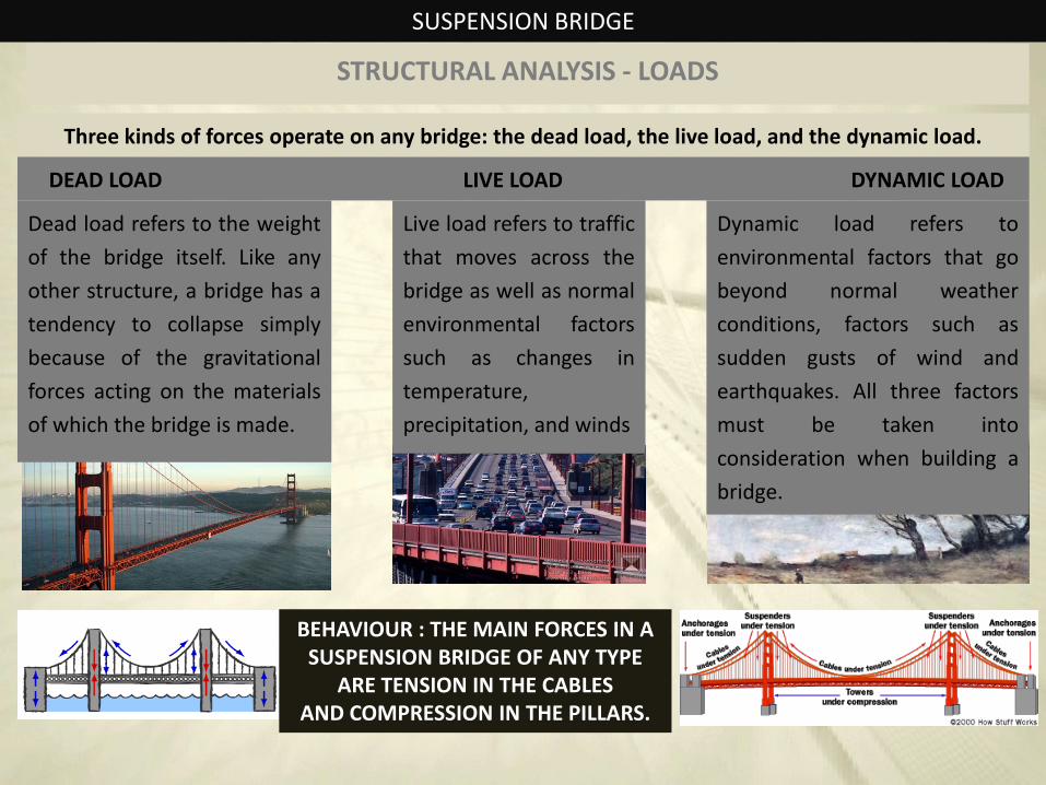
Three kinds of forces operate on any bridge: the dead load, the live load, and the dynamic load.
Live load refers to traffic
that moves across the
bridge as well as normal
environmental factors
such as changes in
temperature,
precipitation, and winds
DEAD LOAD LIVE LOAD DYNAMIC LOAD
Dead load refers to the weight
of the bridge itself. Like any
other structure, a bridge has a
tendency to collapse simply
because of the gravitational
forces acting on the materials
of which the bridge is made.
Dynamic load refers to
environmental factors that go
beyond normal weather
conditions, factors such as
sudden gusts of wind and
earthquakes. All three factors
must be taken into
consideration when building a
bridge.
BEHAVIOUR : THE MAIN FORCES IN A SUSPENSION BRIDGE OF ANY TYPE
ARE TENSION IN THE CABLES AND COMPRESSION IN THE PILLARS.
SUSPENSION BRIDGE
CONSTRUCTION SEQUENCE
1. TOWERS`
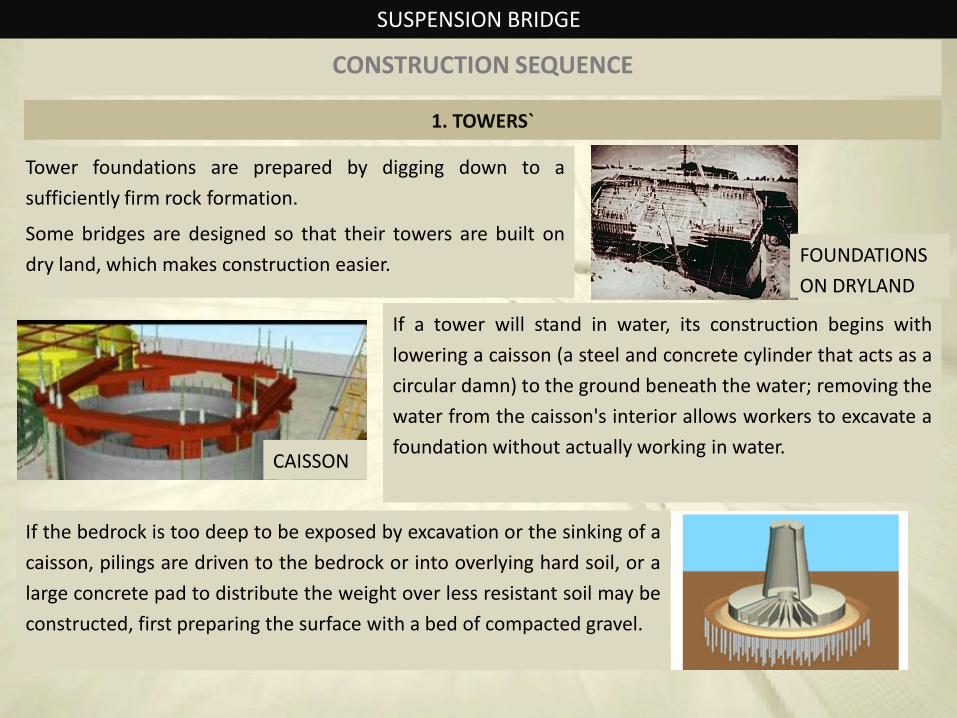
Tower foundations are prepared by digging down to a
sufficiently firm rock formation.
Some bridges are designed so that their towers are built on
dry land, which makes construction easier.
If a tower will stand in water, its construction begins with
lowering a caisson (a steel and concrete cylinder that acts as a
circular damn) to the ground beneath the water; removing the
water from the caisson's interior allows workers to excavate a
foundation without actually working in water.
FOUNDATIONS
ON DRYLAND
CAISSON
If the bedrock is too deep to be exposed by excavation or the sinking of a
caisson, pilings are driven to the bedrock or into overlying hard soil, or a
large concrete pad to distribute the weight over less resistant soil may be
constructed, first preparing the surface with a bed of compacted gravel.
SUSPENSION BRIDGE
CONSTRUCTION SEQUENCE
1. TOWERS`
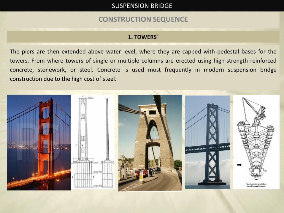
The piers are then extended above water level, where they are capped with pedestal bases for the
towers. From where towers of single or multiple columns are erected using high-strength reinforced
concrete, stonework, or steel. Concrete is used most frequently in modern suspension bridge
construction due to the high cost of steel.
SUSPENSION BRIDGE
CONSTRUCTION SEQUENCE`
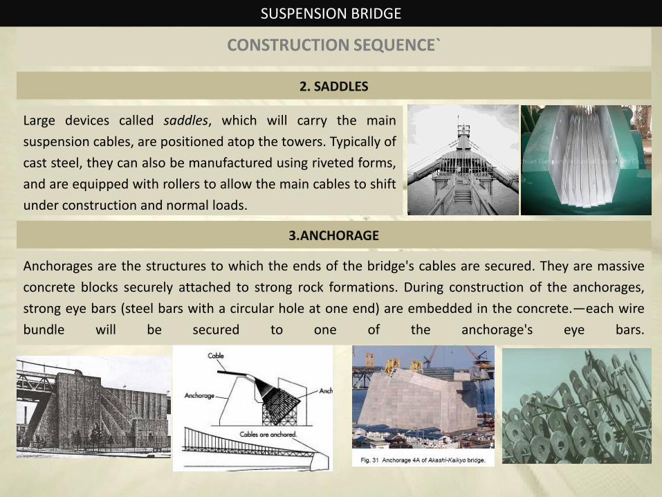
2. SADDLES
Large devices called saddles, which will carry the main
suspension cables, are positioned atop the towers. Typically of
cast steel, they can also be manufactured using riveted forms,
and are equipped with rollers to allow the main cables to shift
under construction and normal loads.
3.ANCHORAGE
Anchorages are the structures to which the ends of the bridge's cables are secured. They are massive
concrete blocks securely attached to strong rock formations. During construction of the anchorages,
strong eye bars (steel bars with a circular hole at one end) are embedded in the concrete.—each wire
bundle will be secured to one of the anchorage's eye bars.
SUSPENSION BRIDGE
CONSTRUCTION SEQUENCE`
4.CATWALKS
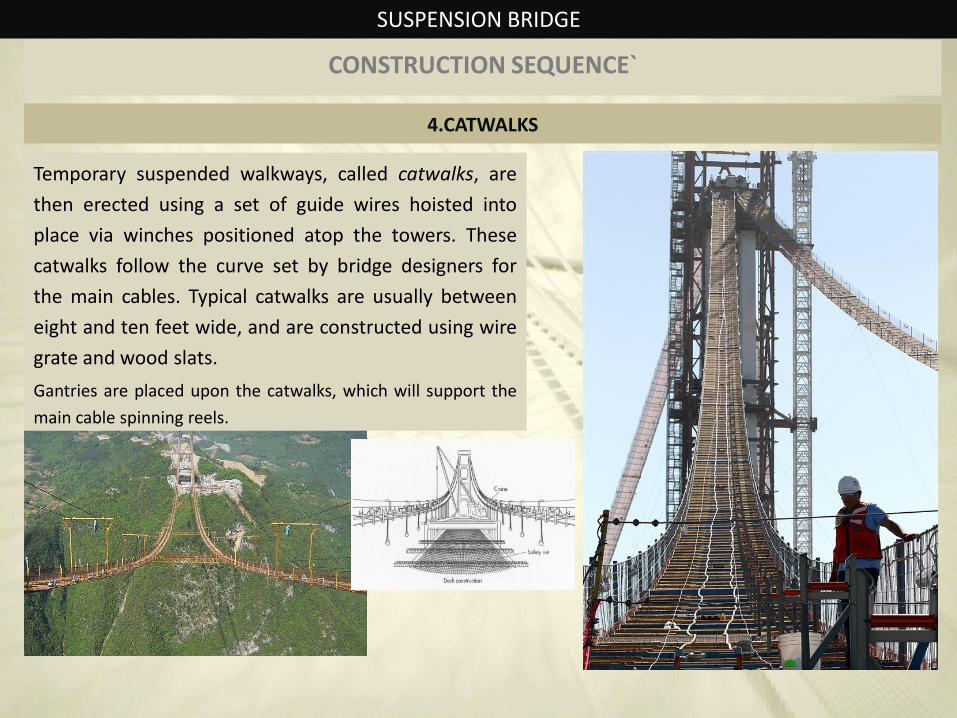
Temporary suspended walkways, called catwalks, are
then erected using a set of guide wires hoisted into
place via winches positioned atop the towers. These
catwalks follow the curve set by bridge designers for
the main cables. Typical catwalks are usually between
eight and ten feet wide, and are constructed using wire
grate and wood slats.
Gantries are placed upon the catwalks, which will support the
main cable spinning reels.
SUSPENSION BRIDGE
CONSTRUCTION SEQUENCE`
5.CABLE SPINNING
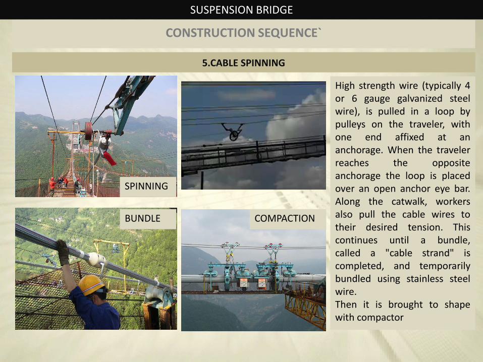
High strength wire (typically 4 or 6 gauge galvanized steel wire), is pulled in a loop by pulleys on the traveler, with one end affixed at an anchorage. When the traveler reaches the opposite anchorage the loop is placed over an open anchor eye bar. Along the catwalk, workers also pull the cable wires to their desired tension. This continues until a bundle, called a "cable strand" is completed, and temporarily bundled using stainless steel wire. Then it is brought to shape with compactor
SPINNING
BUNDLE COMPACTION
SUSPENSION BRIDGE
CONSTRUCTION SEQUENCE`
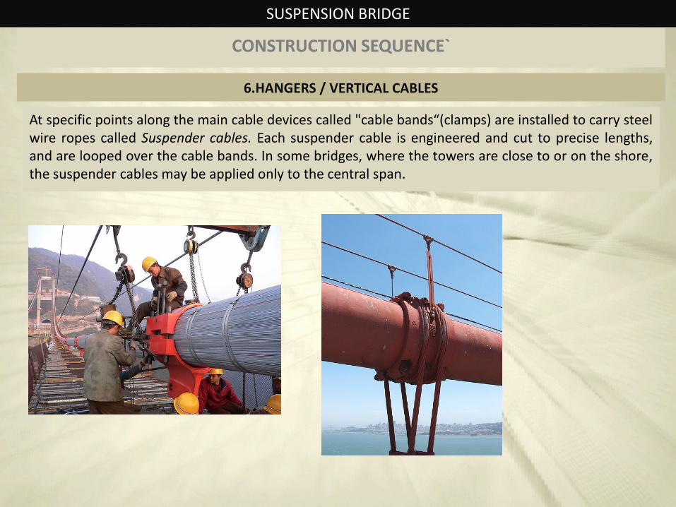
6.HANGERS / VERTICAL CABLES
At specific points along the main cable devices called "cable bands“(clamps) are installed to carry steel wire ropes called Suspender cables. Each suspender cable is engineered and cut to precise lengths, and are looped over the cable bands. In some bridges, where the towers are close to or on the shore, the suspender cables may be applied only to the central span.
SUSPENSION BRIDGE
CONSTRUCTION SEQUENCE`
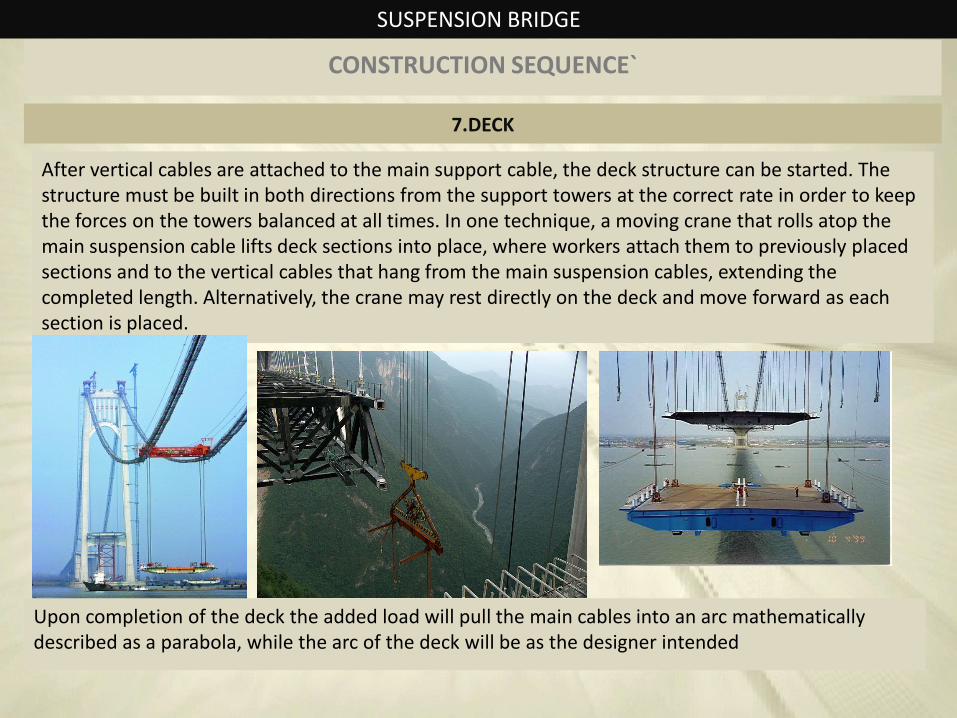
7.DECK
After vertical cables are attached to the main support cable, the deck structure can be started. The structure must be built in both directions from the support towers at the correct rate in order to keep the forces on the towers balanced at all times. In one technique, a moving crane that rolls atop the main suspension cable lifts deck sections into place, where workers attach them to previously placed sections and to the vertical cables that hang from the main suspension cables, extending the completed length. Alternatively, the crane may rest directly on the deck and move forward as each section is placed.
Upon completion of the deck the added load will pull the main cables into an arc mathematically described as a parabola, while the arc of the deck will be as the designer intended
SUSPENSION BRIDGE
CASE OF CABLE STAYED BRIDGE
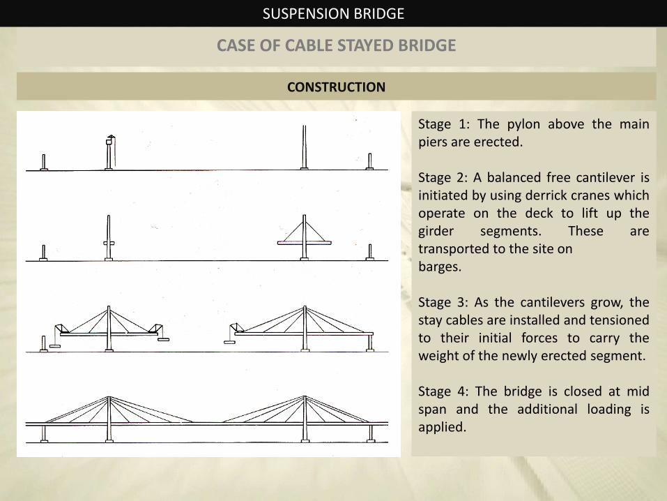
CONSTRUCTION
Stage 1: The pylon above the main piers are erected. Stage 2: A balanced free cantilever is initiated by using derrick cranes which operate on the deck to lift up the girder segments. These are transported to the site on barges. Stage 3: As the cantilevers grow, the stay cables are installed and tensioned to their initial forces to carry the weight of the newly erected segment. Stage 4: The bridge is closed at mid span and the additional loading is applied.
SUSPENSION BRIDGE
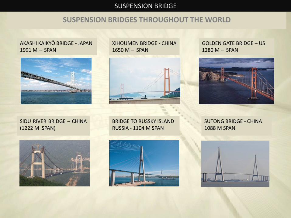
SUSPENSION BRIDGES THROUGHOUT THE WORLD
GOLDEN GATE BRIDGE – US 1280 M – SPAN
SIDU RIVER BRIDGE – CHINA (1222 M SPAN)
AKASHI KAIKYŌ BRIDGE - JAPAN 1991 M – SPAN
XIHOUMEN BRIDGE - CHINA 1650 M – SPAN
BRIDGE TO RUSSKY ISLAND RUSSIA - 1104 M SPAN
SUTONG BRIDGE - CHINA 1088 M SPAN
SUSPENSION BRIDGE
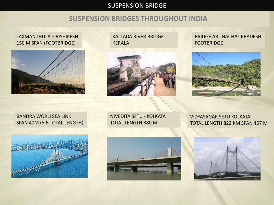
SUSPENSION BRIDGES THROUGHOUT INDIA
LAXMAN JHULA – RISHIKESH 150 M SPAN (FOOTBRIDGE)
KALLADA RIVER BRIDGE-KERALA
BRIDGE ARUNACHAL PRADESH FOOTBRIDGE
BANDRA WORLI SEA LINK SPAN 40M (5.6 TOTAL LENGTH)
NIVEDITA SETU - KOLKATA TOTAL LENGTH 880 M
VIDYASAGAR SETU KOLKATA TOTAL LENGTH 822 KM SPAN 457 M
SUSPENSION BRIDGE
COMPARISION
Advantages over other bridge types
Longer main spans
A suspension bridge can be made out of simple materials such as wood and common wire rope.
Less material may be required than other bridge types, even at spans they can achieve, leading to a reduced construction cost
Except for installation of the initial temporary cables, little or no access from below is required during construction, for example allowing a waterway to remain open while the bridge is built above
May be better to withstand earthquake movements than heavier and more rigid bridges
Disadvantages over other bridge types
Considerable stiffness may be required to prevent the bridge deck vibrating under high winds
The relatively low deck stiffness compared to other (non-suspension) types of bridges makes it more difficult to carry heavy rail traffic where high concentrated live loads occur
SUSPENSION BRIDGE
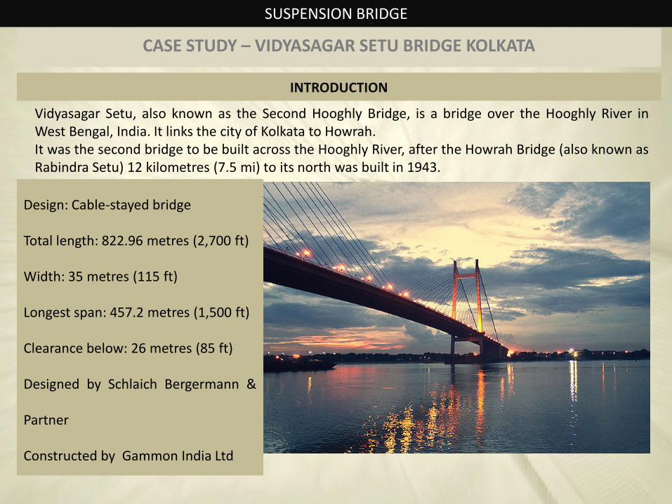
CASE STUDY – VIDYASAGAR SETU BRIDGE KOLKATA
Vidyasagar Setu, also known as the Second Hooghly Bridge, is a bridge over the Hooghly River in West Bengal, India. It links the city of Kolkata to Howrah. It was the second bridge to be built across the Hooghly River, after the Howrah Bridge (also known as Rabindra Setu) 12 kilometres (7.5 mi) to its north was built in 1943.
Design: Cable-stayed bridge
Total length: 822.96 metres (2,700 ft)
Width: 35 metres (115 ft)
Longest span: 457.2 metres (1,500 ft)
Clearance below: 26 metres (85 ft)
Designed by Schlaich Bergermann &
Partner
Constructed by Gammon India Ltd
INTRODUCTION
SUSPENSION BRIDGE
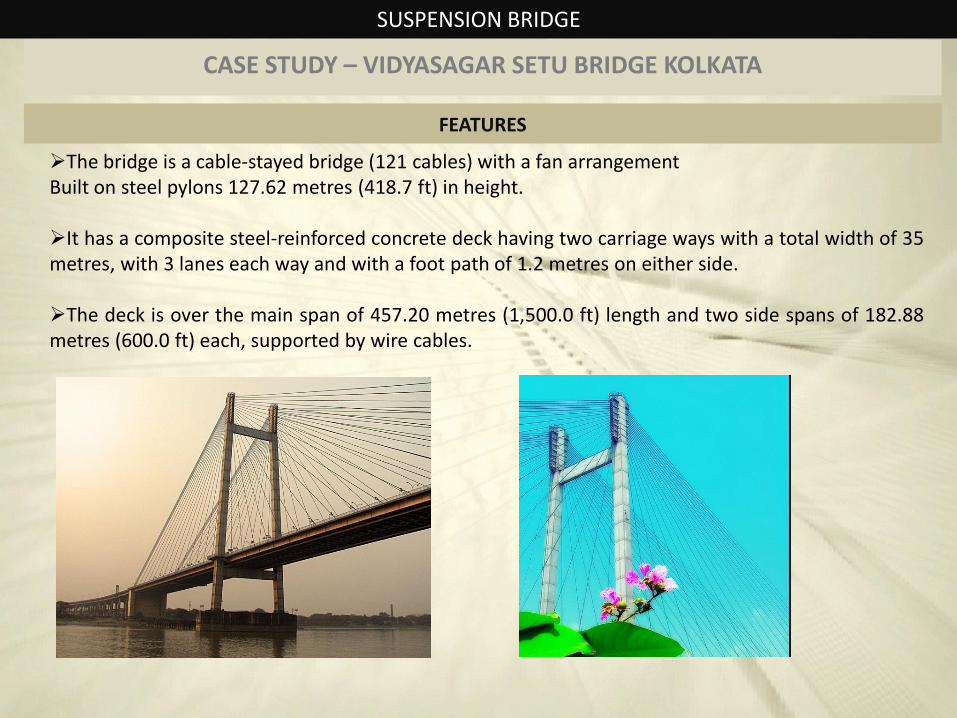
CASE STUDY – VIDYASAGAR SETU BRIDGE KOLKATA
The bridge is a cable-stayed bridge (121 cables) with a fan arrangement Built on steel pylons 127.62 metres (418.7 ft) in height.
It has a composite steel-reinforced concrete deck having two carriage ways with a total width of 35 metres, with 3 lanes each way and with a foot path of 1.2 metres on either side.
The deck is over the main span of 457.20 metres (1,500.0 ft) length and two side spans of 182.88 metres (600.0 ft) each, supported by wire cables.
FEATURES
SUSPENSION BRIDGE
CASE STUDY – VIDYASAGAR SETU BRIDGE KOLKATA
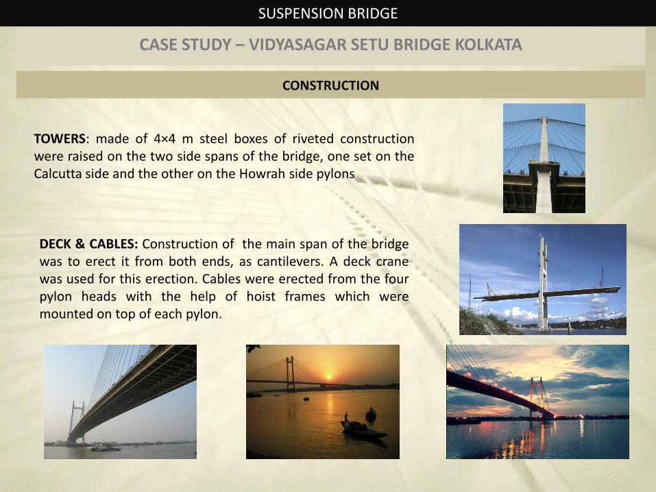
TOWERS: made of 4×4 m steel boxes of riveted construction were raised on the two side spans of the bridge, one set on the Calcutta side and the other on the Howrah side pylons
CONSTRUCTION
DECK & CABLES: Construction of the main span of the bridge was to erect it from both ends, as cantilevers. A deck crane was used for this erection. Cables were erected from the four pylon heads with the help of hoist frames which were mounted on top of each pylon.