Embed Size (px)
DESCRIPTION
Concept
Citation preview
Suspension Bridge For Loading LNG in Equatorial Guinea
Al Chernosky Engineering Manager
EG LNG Train 1 EG Global LNG Services, Ltd
Marathon Oil Corporation Houston, Texas
Andy McGhie Bridge & Marine Facilities Engineer
EG LNG Train 1 Technical Advisor to the Project Management Team
EG LNG Operations S.A. Bioko Norte, Equatorial Guinea
Prepared for presentation at:
GasTech 2006
4 – 7 December 2006, Abu Dhabi, U.A.E.
Gastec - 2006
Chernosky 2
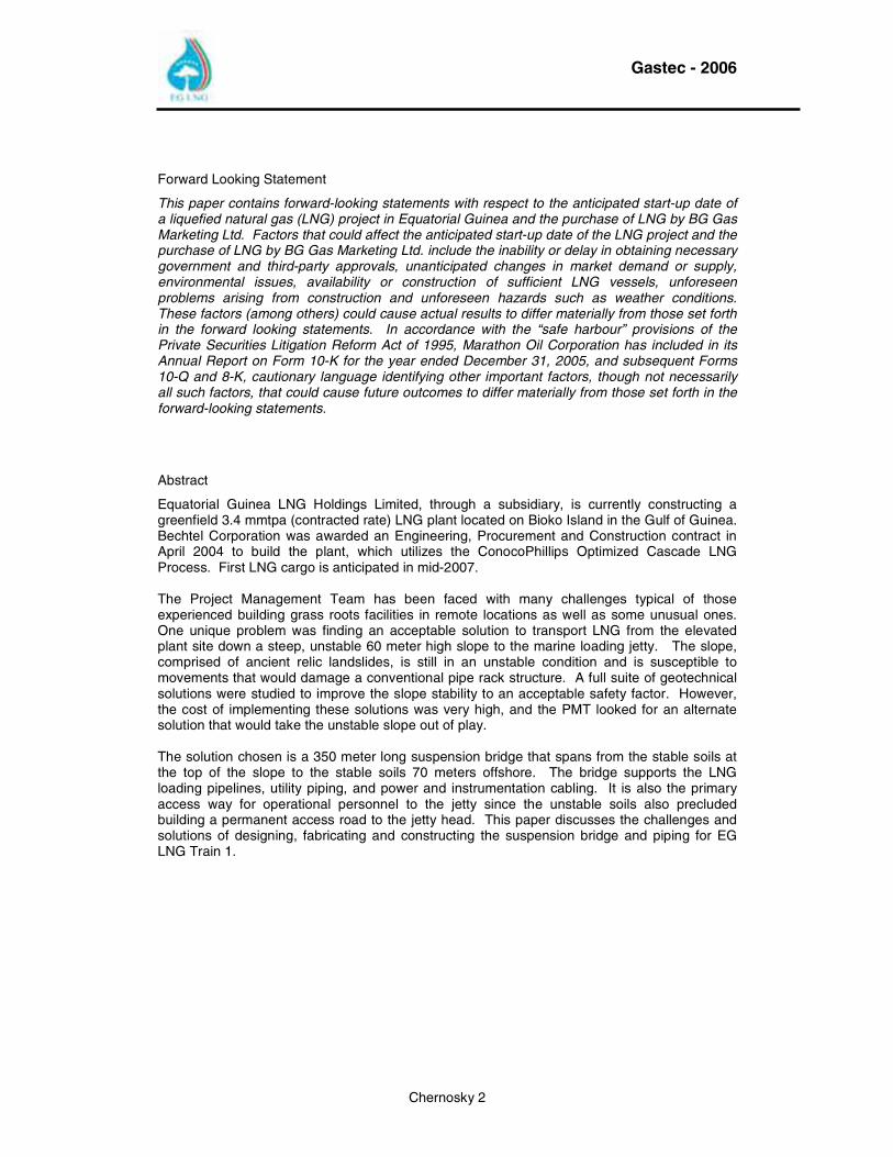
Forward Looking Statement
This paper contains forward-looking statements with respect to the anticipated start-up date of a liquefied natural gas (LNG) project in Equatorial Guinea and the purchase of LNG by BG Gas Marketing Ltd. Factors that could affect the anticipated start-up date of the LNG project and the purchase of LNG by BG Gas Marketing Ltd. include the inability or delay in obtaining necessary government and third-party approvals, unanticipated changes in market demand or supply, environmental issues, availability or construction of sufficient LNG vessels, unforeseen problems arising from construction and unforeseen hazards such as weather conditions. These factors (among others) could cause actual results to differ materially from those set forth in the forward looking statements. In accordance with the “safe harbour” provisions of the Private Securities Litigation Reform Act of 1995, Marathon Oil Corporation has included in its Annual Report on Form 10-K for the year ended December 31, 2005, and subsequent Forms 10-Q and 8-K, cautionary language identifying other important factors, though not necessarily all such factors, that could cause future outcomes to differ materially from those set forth in the forward-looking statements.
Abstract
Equatorial Guinea LNG Holdings Limited, through a subsidiary, is currently constructing a greenfield 3.4 mmtpa (contracted rate) LNG plant located on Bioko Island in the Gulf of Guinea. Bechtel Corporation was awarded an Engineering, Procurement and Construction contract in April 2004 to build the plant, which utilizes the ConocoPhillips Optimized Cascade LNG Process. First LNG cargo is anticipated in mid-2007. The Project Management Team has been faced with many challenges typical of those experienced building grass roots facilities in remote locations as well as some unusual ones. One unique problem was finding an acceptable solution to transport LNG from the elevated plant site down a steep, unstable 60 meter high slope to the marine loading jetty. The slope, comprised of ancient relic landslides, is still in an unstable condition and is susceptible to movements that would damage a conventional pipe rack structure. A full suite of geotechnical solutions were studied to improve the slope stability to an acceptable safety factor. However, the cost of implementing these solutions was very high, and the PMT looked for an alternate solution that would take the unstable slope out of play. The solution chosen is a 350 meter long suspension bridge that spans from the stable soils at the top of the slope to the stable soils 70 meters offshore. The bridge supports the LNG loading pipelines, utility piping, and power and instrumentation cabling. It is also the primary access way for operational personnel to the jetty since the unstable soils also precluded building a permanent access road to the jetty head. This paper discusses the challenges and solutions of designing, fabricating and constructing the suspension bridge and piping for EG LNG Train 1.
Gastec - 2006
Chernosky 3
INDEX OF CONTENTS
1.0 INTRODUCTION ........................................................................................................................ 5
2.0 PROJECT................................................................................................................................... 7
2.1 PROJECT OWNERSHIP................................................................................................................... 7
2.2 PROJECT LOCATION...................................................................................................................... 7
3.0 GEOLOGIC/GEOTECHINCAL CONDITIONS........................................................................... 8
3.1 BIOKO ISLAND............................................................................................................................... 8
3.2 PROJECT GEOTECHNICAL.............................................................................................................. 9
4.0 LNG LOADING LINE OPTIONS.............................................................................................. 11
4.1 INITIAL TRUSS CONCEPTS ........................................................................................................... 11
4.2 OPEN CUT.................................................................................................................................. 12
4.3 TUNNEL ...................................................................................................................................... 12
4.4 CABLE SUPPORT PIPELINE BRIDGE.............................................................................................. 12
5.0 SUSPENSION BRIDGE DESIGN ............................................................................................ 13
5.1 BRIDGE DESIGN TEAM................................................................................................................. 13
5.2 BRIDGE SERVICE LOAD REQUIREMENTS....................................................................................... 13
5.3 TRADITIONAL CABLE PIPELINE BRIDGE......................................................................................... 14
5.4 SUSPENSION BRIDGE GEOMETRY ................................................................................................ 15
5.5 LAND FOUNDATION DESIGN......................................................................................................... 18
5.6 MARINE FOUNDATION DESIGN ..................................................................................................... 18
5.7 AERODYNAMIC DESIGN ............................................................................................................... 19
6.0 INSTALLATION ENGINEERING & DESIGN .......................................................................... 20
7.0 FABRICATION......................................................................................................................... 21
7.1 STRUCTURAL STEEL ................................................................................................................... 21
7.2 SUSPENSION & HANGERS CABLES............................................................................................... 23
8.0 CONSTRUCTION..................................................................................................................... 24
8.1 SITE PREPARATION..................................................................................................................... 24
8.2 LAND TOWER & ANCHOR FOUNDATION ........................................................................................ 25
Gastec - 2006
Chernosky 4
8.3 MARINE TOWER & ANCHOR FOUNDATION..................................................................................... 26
9.0 BRIDGE ERECTION ................................................................................................................ 27
9.1 LAND TOWER ERECTION ............................................................................................................. 27
9.2 MARINE TOWER ERECTION.......................................................................................................... 28
9.3 BACKSTAY CABLE ERECTION....................................................................................................... 30
9.4 MAIN SPAN CABLE ERECTION...................................................................................................... 31
9.5 TRACK CABLES & HIGHLINE......................................................................................................... 32
9.6 CABLE CLAMP & SUSPENDER ERECTION...................................................................................... 33
9.7 PRE-ASSEMBLY OF DECK UNITS .................................................................................................. 34
9.8 MAIN SPAN DECK ERECTION ....................................................................................................... 35
9.9 PIPE INSTALLATION ..................................................................................................................... 37
10.0 PROJECT SCHEDULE............................................................................................................ 38
11.0 MAJOR PARTIES INVOLVED................................................................................................. 38
12.0 ABOUT THE AUTHORS.......................................................................................................... 39
Gastec - 2006
Chernosky 5
1.0 Introduction
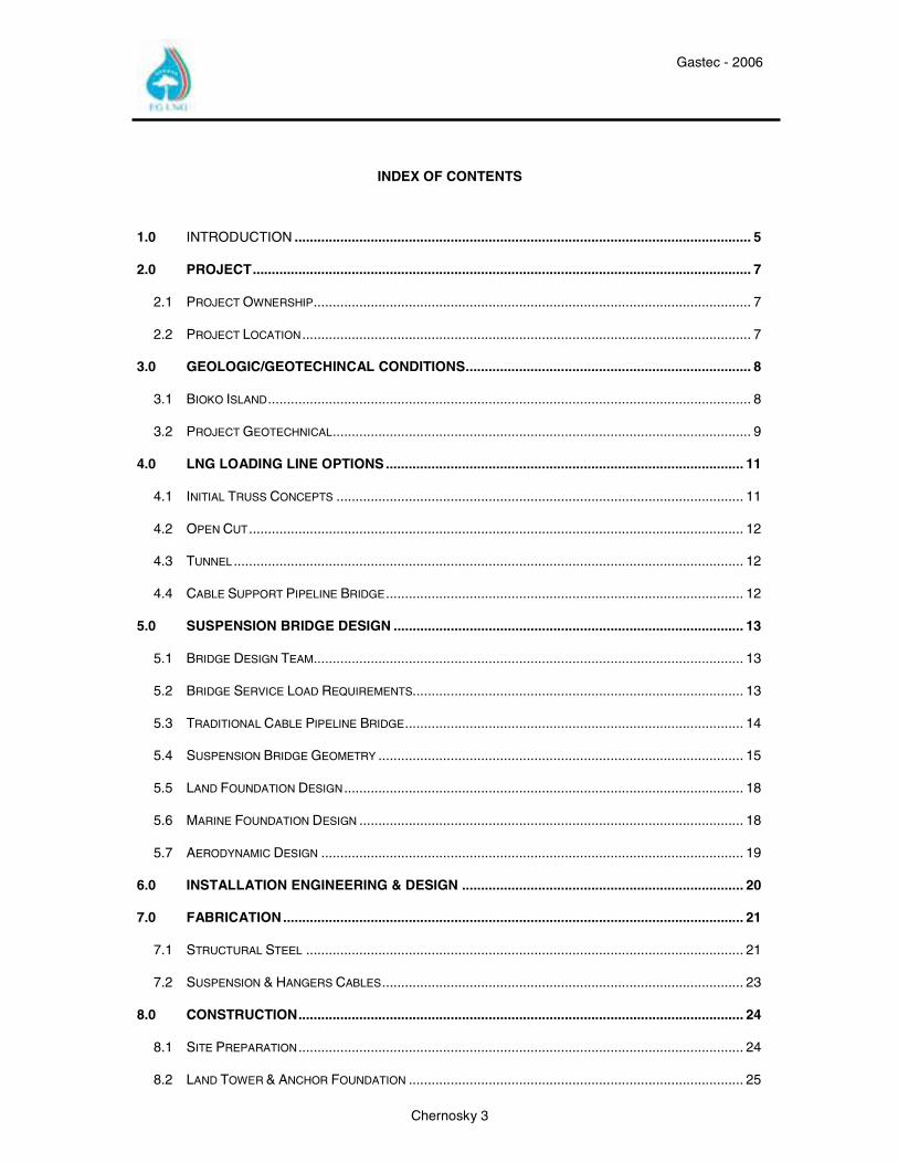
Equatorial Guinea LNG Holdings Limited, through a subsidiary (EG LNG), is currently constructing the greenfield 3.4 mmtpa (contracted rate) EG LNG Train 1 plant to monetize the gas reserves of the Alba gas and condensate field. EG LNG Shareholders include Marathon Oil Corporation, through a subsidiary (Marathon); Sociedad Nacional de Gas de Guinea Ecuatorial (Sonagas, G.E., the National Gas Company of Equatorial Guinea, share transfer pending); Mitsui & Co., Ltd., and Marubeni Gas Development Co., Ltd. The Alba Field, located approximately 25 km northwest of Bioko Island in the Gulf of Guinea, began production in December 1991. CMS NOMECO Oil & Gas Co. purchased operator rights of the Alba Field from Walter International, Inc. in February 1995 and subsequently drilled additional wells and expanded the onshore condensate processing facilities to include LPG production facilities. In April 2001 CMS Energy, Noble Energy and Compania Nacional de Petroleos de Guinea Ecuatorial (GEPetrol the National Oil Company of Equatorial Guinea) completed another expansion project that included offshore facilities and methanol production facilities. Atlantic Methanol Production Company (AMPCO) (45% CMS Energy, 45% Noble Energy, 10% GEPetrol) was created to operate the methanol facilities. Excess gas production was re-injected into the Alba reservoir.
Punta Europa Satellite Image Acquired February 2003
In January 2002, Marathon acquired CMS Energy’s interest in the Alba Field and together with the other Alba Field PSC Contractors (Noble Energy, Globex and GEPetrol) commenced a production expansion project. The expansion project increased the design production capacity to 800 MMCFD, 57,000 BCPD and 16,000 BPD of LPG products. The expansion project became fully operational in 2005. Excess residue gas production continues to be re-injected into the Alba reservoir. In parallel with the production expansion project the Alba PSC initiated a “Gas Monetization Study” to determine the optimum method for monetizing Alba Field residue gas. By the end of 2002, LNG was selected as the preferred method for monetizing the residue gas. Bechtel Corporation was awarded the Front End Engineering Design (FEED) contract in November 2002 for a LNG facility utilizing the ConocoPhillips Optimized Cascade LNG Process. In January 2004 Bechtel completed the FEED work, commenced pre-EPC groundbreaking activities at the plant site, and placed orders for long lead equipment. In June 2004 the EG LNG Train 1 Project Final Investment Decision (FID) was taken by EG LNG Shareholders.
Gastec - 2006
Chernosky 6
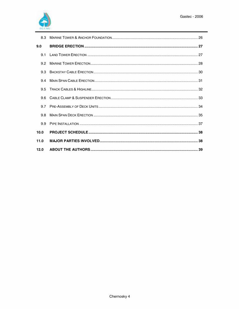
Punta Europe Layout with LNG Train 1 Plant and Alba Gas Plant
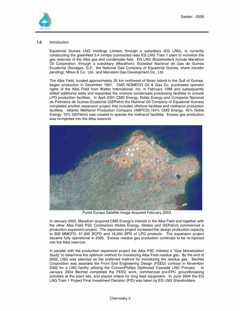
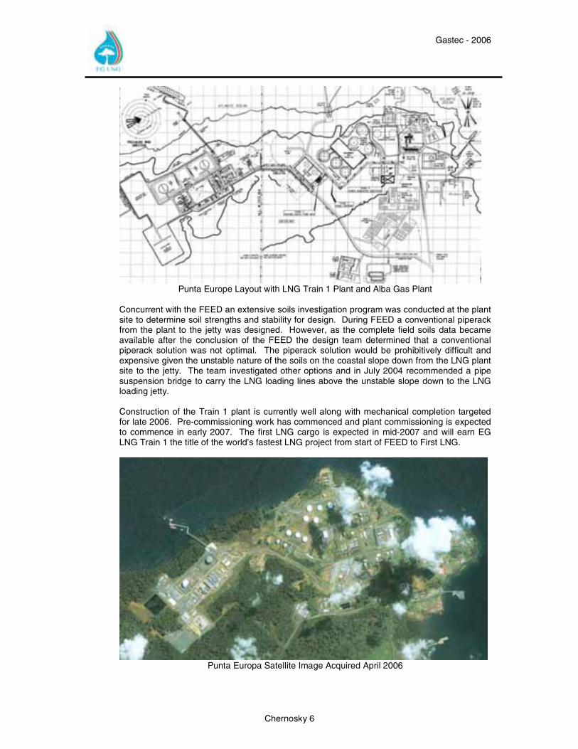
Concurrent with the FEED an extensive soils investigation program was conducted at the plant site to determine soil strengths and stability for design. During FEED a conventional piperack from the plant to the jetty was designed. However, as the complete field soils data became available after the conclusion of the FEED the design team determined that a conventional piperack solution was not optimal. The piperack solution would be prohibitively difficult and expensive given the unstable nature of the soils on the coastal slope down from the LNG plant site to the jetty. The team investigated other options and in July 2004 recommended a pipe suspension bridge to carry the LNG loading lines above the unstable slope down to the LNG loading jetty. Construction of the Train 1 plant is currently well along with mechanical completion targeted for late 2006. Pre-commissioning work has commenced and plant commissioning is expected to commence in early 2007. The first LNG cargo is expected in mid-2007 and will earn EG LNG Train 1 the title of the world’s fastest LNG project from start of FEED to First LNG.
Punta Europa Satellite Image Acquired April 2006
Gastec - 2006
Chernosky 7
2.0 Project
2.1 Project Ownership
EG LNG shareholders are Marathon, with a 60 percent interest, Sonagas, G.E., with a 25 percent interest (share transfer pending), as well as Marubeni Gas Development Co., Ltd., and Mitsui & Co., Ltd., which hold the remaining 6.5 percent and 8.5 percent interest, respectively.
2.2 Project Location
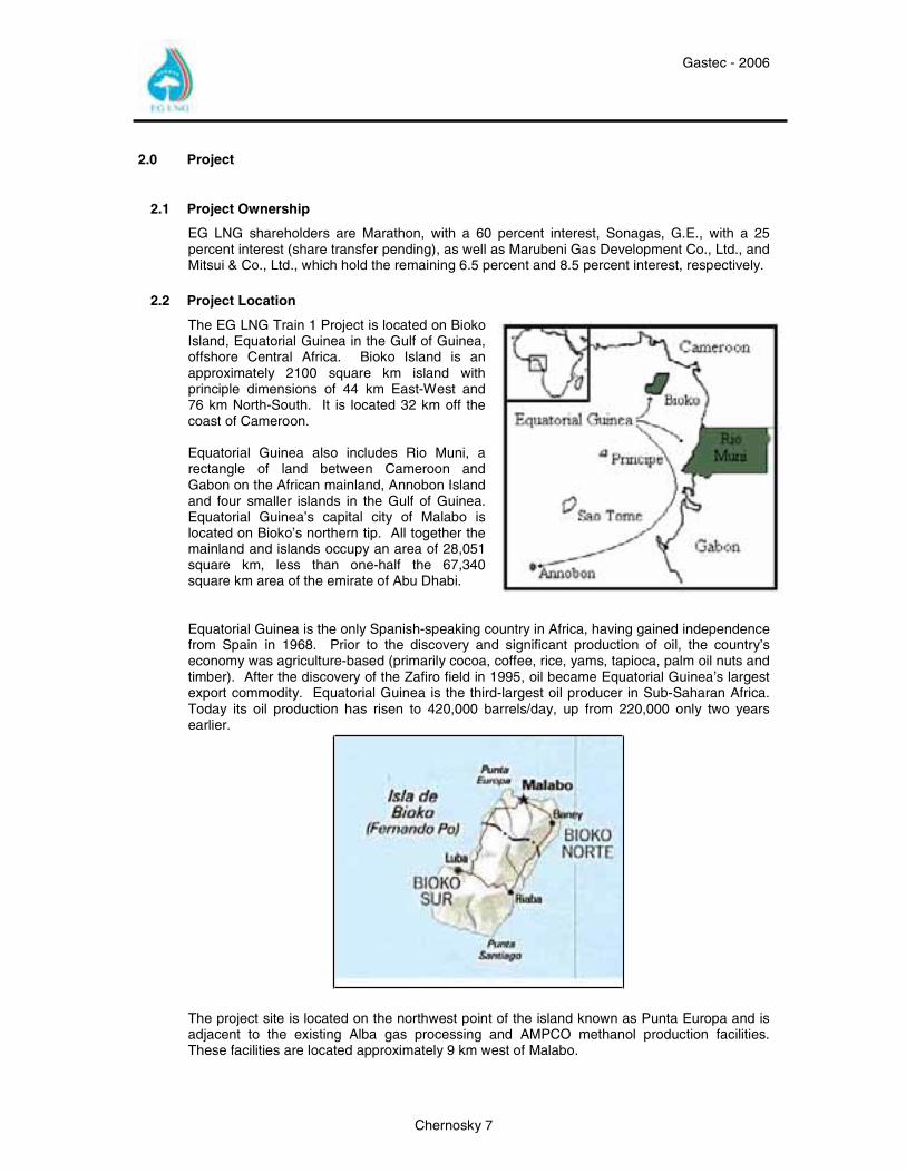
The EG LNG Train 1 Project is located on Bioko Island, Equatorial Guinea in the Gulf of Guinea, offshore Central Africa. Bioko Island is an approximately 2100 square km island with principle dimensions of 44 km East-West and 76 km North-South. It is located 32 km off the coast of Cameroon.
Equatorial Guinea also includes Rio Muni, a rectangle of land between Cameroon and Gabon on the African mainland, Annobon Island and four smaller islands in the Gulf of Guinea. Equatorial Guinea’s capital city of Malabo is located on Bioko’s northern tip. All together the mainland and islands occupy an area of 28,051 square km, less than one-half the 67,340 square km area of the emirate of Abu Dhabi.
Equatorial Guinea is the only Spanish-speaking country in Africa, having gained independence from Spain in 1968. Prior to the discovery and significant production of oil, the country’s economy was agriculture-based (primarily cocoa, coffee, rice, yams, tapioca, palm oil nuts and timber). After the discovery of the Zafiro field in 1995, oil became Equatorial Guinea’s largest export commodity. Equatorial Guinea is the third-largest oil producer in Sub-Saharan Africa. Today its oil production has risen to 420,000 barrels/day, up from 220,000 only two years earlier.
The project site is located on the northwest point of the island known as Punta Europa and is adjacent to the existing Alba gas processing and AMPCO methanol production facilities. These facilities are located approximately 9 km west of Malabo.
Gastec - 2006
Chernosky 8
3.0 Geologic/Geotechincal Conditions
3.1 Bioko Island
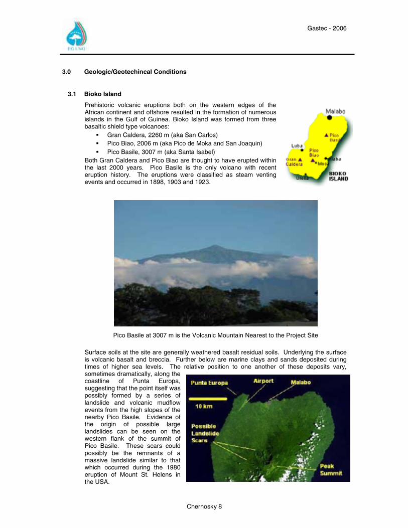
Prehistoric volcanic eruptions both on the western edges of the African continent and offshore resulted in the formation of numerous islands in the Gulf of Guinea. Bioko Island was formed from three basaltic shield type volcanoes:
Gran Caldera, 2260 m (aka San Carlos) Pico Biao, 2006 m (aka Pico de Moka and San Joaquin) Pico Basile, 3007 m (aka Santa Isabel)
Both Gran Caldera and Pico Biao are thought to have erupted within the last 2000 years. Pico Basile is the only volcano with recent eruption history. The eruptions were classified as steam venting events and occurred in 1898, 1903 and 1923.
Pico Basile at 3007 m is the Volcanic Mountain Nearest to the Project Site Surface soils at the site are generally weathered basalt residual soils. Underlying the surface is volcanic basalt and breccia. Further below are marine clays and sands deposited during times of higher sea levels. The relative position to one another of these deposits vary, sometimes dramatically, along the coastline of Punta Europa, suggesting that the point itself was possibly formed by a series of landslide and volcanic mudflow events from the high slopes of the nearby Pico Basile. Evidence of the origin of possible large landslides can be seen on the western flank of the summit of Pico Basile. These scars could possibly be the remnants of a massive landslide similar to that which occurred during the 1980 eruption of Mount St. Helens in the USA.
Gastec - 2006
Chernosky 9
3.2 Project Geotechnical
Soil borings taken for the Alba Gas Plant expansion project in 2002 and for the EG LNG Train 1 project in 2003 found a variation of soil stratigraphy along the coastal slope. The significance of these findings confirmed earlier work that the coastal slope was complex geotechnically and would present challenges to the design team. Such a challenge surfaced in 2003 during the construction of the Alba Gas Plant Expansion Project. While constructing a piperack right of way down the coastal slope using traditional cut and fill methods, an ancient relic landslide was reactivated. The landslide not only endangered the ongoing construction project, but also had the potential to endanger an existing condensate storage tank. Remediation included removal of the new fill material, the installation of 50,000 tons of rock at the toe of the slope and dozens of horizontal and vertical water wells to lower the water table. After months of work and movement of tens of thousands of cubic meters of soil the landslide was stopped.
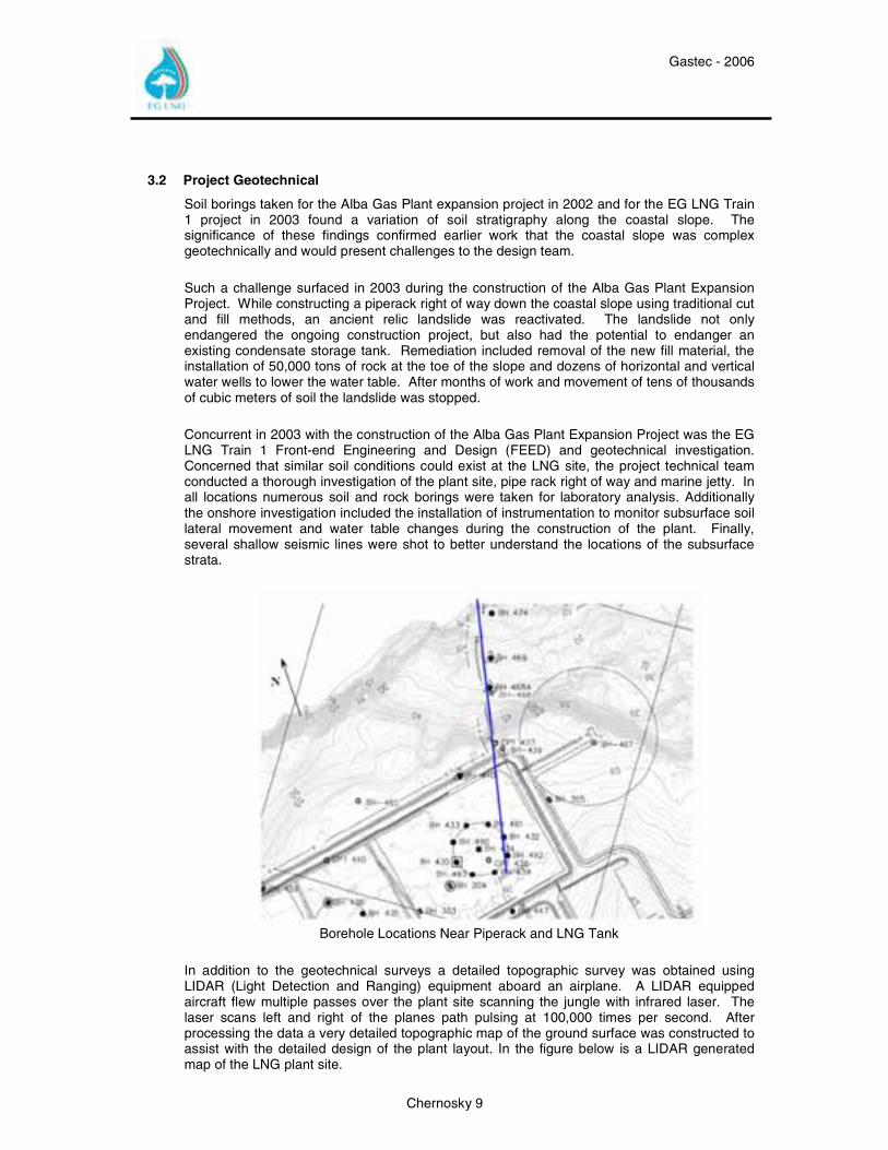
Concurrent in 2003 with the construction of the Alba Gas Plant Expansion Project was the EG LNG Train 1 Front-end Engineering and Design (FEED) and geotechnical investigation. Concerned that similar soil conditions could exist at the LNG site, the project technical team conducted a thorough investigation of the plant site, pipe rack right of way and marine jetty. In all locations numerous soil and rock borings were taken for laboratory analysis. Additionally the onshore investigation included the installation of instrumentation to monitor subsurface soil lateral movement and water table changes during the construction of the plant. Finally, several shallow seismic lines were shot to better understand the locations of the subsurface strata.
Borehole Locations Near Piperack and LNG Tank
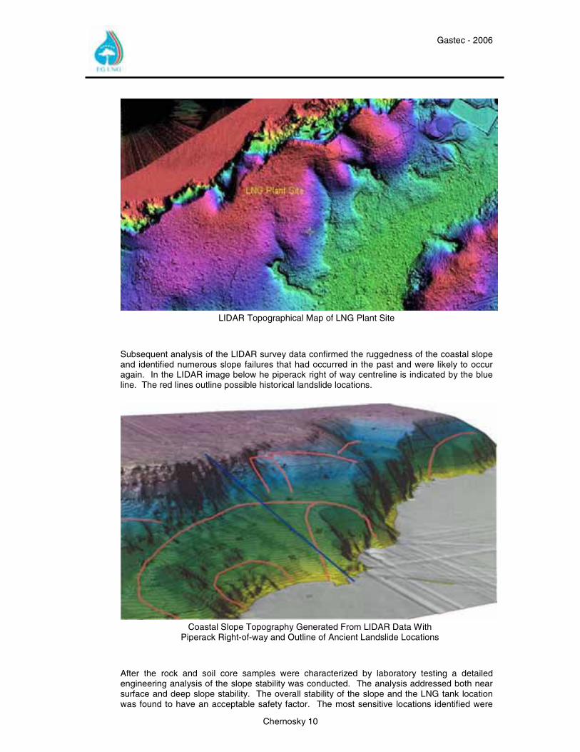
In addition to the geotechnical surveys a detailed topographic survey was obtained using LIDAR (Light Detection and Ranging) equipment aboard an airplane. A LIDAR equipped aircraft flew multiple passes over the plant site scanning the jungle with infrared laser. The laser scans left and right of the planes path pulsing at 100,000 times per second. After processing the data a very detailed topographic map of the ground surface was constructed to assist with the detailed design of the plant layout. In the figure below is a LIDAR generated map of the LNG plant site.
Gastec - 2006
Chernosky 10
LIDAR Topographical Map of LNG Plant Site
Subsequent analysis of the LIDAR survey data confirmed the ruggedness of the coastal slope and identified numerous slope failures that had occurred in the past and were likely to occur again. In the LIDAR image below he piperack right of way centreline is indicated by the blue line. The red lines outline possible historical landslide locations.
Coastal Slope Topography Generated From LIDAR Data With
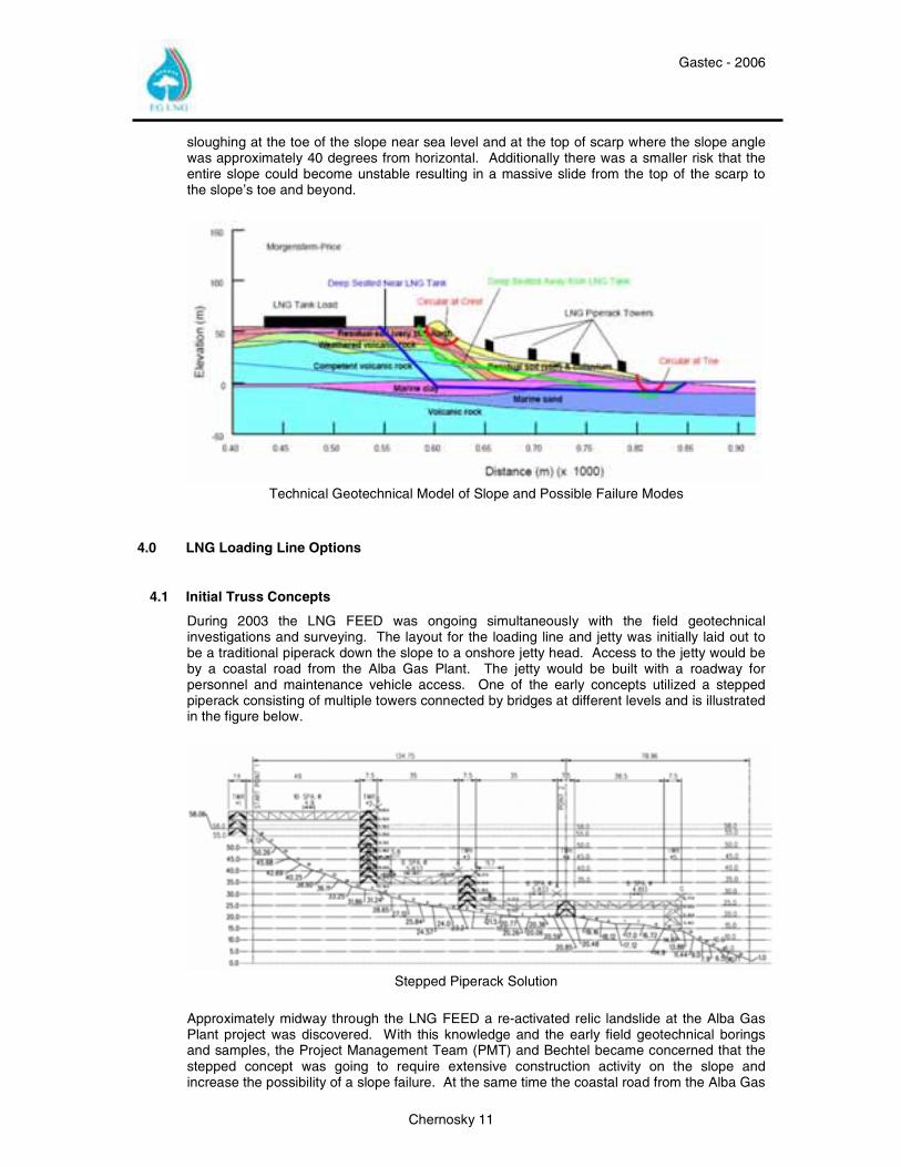
Piperack Right-of-way and Outline of Ancient Landslide Locations After the rock and soil core samples were characterized by laboratory testing a detailed engineering analysis of the slope stability was conducted. The analysis addressed both near surface and deep slope stability. The overall stability of the slope and the LNG tank location was found to have an acceptable safety factor. The most sensitive locations identified were
Gastec - 2006
Chernosky 11
sloughing at the toe of the slope near sea level and at the top of scarp where the slope angle was approximately 40 degrees from horizontal. Additionally there was a smaller risk that the entire slope could become unstable resulting in a massive slide from the top of the scarp to the slope’s toe and beyond.
Technical Geotechnical Model of Slope and Possible Failure Modes
4.0 LNG Loading Line Options
4.1 Initial Truss Concepts
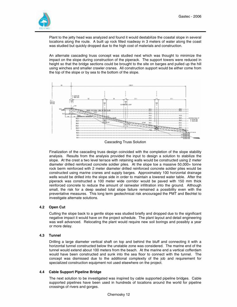
During 2003 the LNG FEED was ongoing simultaneously with the field geotechnical investigations and surveying. The layout for the loading line and jetty was initially laid out to be a traditional piperack down the slope to a onshore jetty head. Access to the jetty would be by a coastal road from the Alba Gas Plant. The jetty would be built with a roadway for personnel and maintenance vehicle access. One of the early concepts utilized a stepped piperack consisting of multiple towers connected by bridges at different levels and is illustrated in the figure below.
Stepped Piperack Solution
Approximately midway through the LNG FEED a re-activated relic landslide at the Alba Gas Plant project was discovered. With this knowledge and the early field geotechnical borings and samples, the Project Management Team (PMT) and Bechtel became concerned that the stepped concept was going to require extensive construction activity on the slope and increase the possibility of a slope failure. At the same time the coastal road from the Alba Gas
Gastec - 2006
Chernosky 12
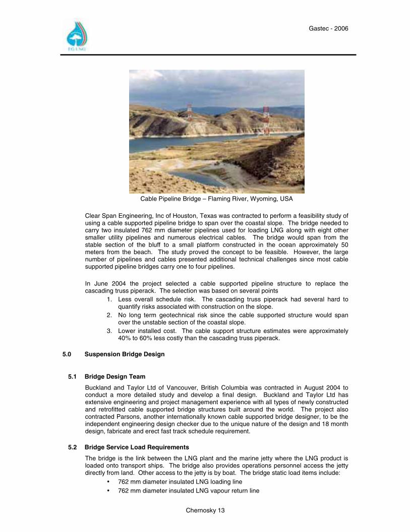
Plant to the jetty head was analyzed and found it would destabilize the coastal slope in several locations along the route. A built up rock filled roadway in 3 meters of water along the coast was studied but quickly dropped due to the high cost of materials and construction. An alternate cascading truss concept was studied next which was thought to minimize the impact on the slope during construction of the piperack. The support towers were reduced in height so that the bridge sections could be brought to the site on barges and pulled up the hill using winches and smaller crawler cranes. All construction support would be either come from the top of the slope or by sea to the bottom of the slope.
Cascading Truss Solution
Finalization of the cascading truss design coincided with the completion of the slope stability analysis. Results from the analysis provided the input to design a solution to stabilize the slope. At the crest a two level terrace with retaining walls would be constructed using 2 meter diameter drilled reinforced concrete soldier piles. At the slope toe a massive 50,000+ tonne rock berm reinforced with 2 meter diameter drilled reinforced concrete soldier piles would be constructed using marine cranes and supply barges. Approximately 100 horizontal drainage wells would be drilled into the slope side in order to maintain a lowered water table. After the piperack was constructed a 100 meter wide corridor would be paved with 150 mm thick reinforced concrete to reduce the amount of rainwater infiltration into the ground. Although small, the risk for a deep seated total slope failure remained a possibility even with the preventative measures. This long term geotechnical risk encouraged the PMT and Bechtel to investigate alternate solutions.
4.2 Open Cut
Cutting the slope back to a gentle slope was studied briefly and dropped due to the significant negative impact it would have on the project schedule. The plant layout and detail engineering was well advanced. Relocating the plant would require new soil borings and possibly a year or more delay.
4.3 Tunnel
Drilling a large diameter vertical shaft on top and behind the bluff and connecting it with a horizontal tunnel constructed below the unstable zone was considered. The marine end of the tunnel would extend about 100 meters from the beach. At the marine end a vertical cofferdam would have been constructed and sunk into the sea floor to connect with the tunnel. The concept was dismissed due to the additional complexity of the job and requirement for specialized construction equipment not used elsewhere on the project.
4.4 Cable Support Pipeline Bridge
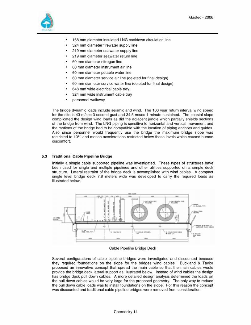
The next solution to be investigated was inspired by cable supported pipeline bridges. Cable supported pipelines have been used in hundreds of locations around the world for pipeline crossings of rivers and gorges.
Gastec - 2006
Chernosky 13
Cable Pipeline Bridge – Flaming River, Wyoming, USA
Clear Span Engineering, Inc of Houston, Texas was contracted to perform a feasibility study of using a cable supported pipeline bridge to span over the coastal slope. The bridge needed to carry two insulated 762 mm diameter pipelines used for loading LNG along with eight other smaller utility pipelines and numerous electrical cables. The bridge would span from the stable section of the bluff to a small platform constructed in the ocean approximately 50 meters from the beach. The study proved the concept to be feasible. However, the large number of pipelines and cables presented additional technical challenges since most cable supported pipeline bridges carry one to four pipelines. In June 2004 the project selected a cable supported pipeline structure to replace the cascading truss piperack. The selection was based on several points
1. Less overall schedule risk. The cascading truss piperack had several hard to quantify risks associated with construction on the slope.
2. No long term geotechnical risk since the cable supported structure would span over the unstable section of the coastal slope.
3. Lower installed cost. The cable support structure estimates were approximately 40% to 60% less costly than the cascading truss piperack.
5.0 Suspension Bridge Design
5.1 Bridge Design Team
Buckland and Taylor Ltd of Vancouver, British Columbia was contracted in August 2004 to conduct a more detailed study and develop a final design. Buckland and Taylor Ltd has extensive engineering and project management experience with all types of newly constructed and retrofitted cable supported bridge structures built around the world. The project also contracted Parsons, another internationally known cable supported bridge designer, to be the independent engineering design checker due to the unique nature of the design and 18 month design, fabricate and erect fast track schedule requirement.
5.2 Bridge Service Load Requirements
The bridge is the link between the LNG plant and the marine jetty where the LNG product is loaded onto transport ships. The bridge also provides operations personnel access the jetty directly from land. Other access to the jetty is by boat. The bridge static load items include:
• 762 mm diameter insulated LNG loading line • 762 mm diameter insulated LNG vapour return line
Gastec - 2006
Chernosky 14
• 168 mm diameter insulated LNG cooldown circulation line • 324 mm diameter firewater supply line • 219 mm diameter seawater supply line • 219 mm diameter seawater return line • 60 mm diameter nitrogen line • 60 mm diameter instrument air line • 60 mm diameter potable water line • 60 mm diameter service air line (deleted for final design) • 60 mm diameter service water line (deleted for final design) • 648 mm wide electrical cable tray • 324 mm wide instrument cable tray • personnel walkway
The bridge dynamic loads include seismic and wind. The 100 year return interval wind speed for the site is 43 m/sec 3 second gust and 34.5 m/sec 1 minute sustained. The coastal slope complicated the design wind loads as did the adjacent jungle which partially shields sections of the bridge from wind. The LNG piping is sensitive to horizontal and vertical movement and the motions of the bridge had to be compatible with the location of piping anchors and guides. Also since personnel would frequently use the bridge the maximum bridge slope was restricted to 10% and motion accelerations restricted below those levels which caused human discomfort.
5.3 Traditional Cable Pipeline Bridge
Initially a simple cable supported pipeline was investigated. These types of structures have been used for single and multiple pipelines and other utilities supported on a simple deck structure. Lateral restraint of the bridge deck is accomplished with wind cables. A compact single level bridge deck 7.8 meters wide was developed to carry the required loads as illustrated below.
Cable Pipeline Bridge Deck
Several configurations of cable pipeline bridges were investigated and discounted because they required foundations on the slope for the bridges wind cables. Buckland & Taylor proposed an innovative concept that spread the main cable so that the main cables would provide the bridge deck lateral support as illustrated below. Instead of wind cables the design has bridge deck pull down cables. A more detailed design analysis determined the loads on the pull down cables would be very large for the proposed geometry. The only way to reduce the pull down cable loads was to install foundations on the slope. For this reason the concept was discounted and traditional cable pipeline bridges were removed from consideration.
Gastec - 2006
Chernosky 15
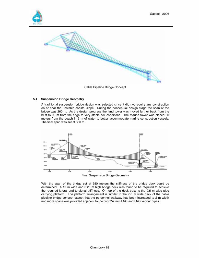
Cable Pipeline Bridge Concept
5.4 Suspension Bridge Geometry
A traditional suspension bridge design was selected since it did not require any construction on or near the unstable coastal slope. During the conceptual design stage the span of the bridge was 260 m. As the design progress the land tower was moved further back from the bluff to 90 m from the edge to very stable soil conditions. The marine tower was placed 80 meters from the beach in 5 m of water to better accommodate marine construction vessels. The final span was set at 350 m.
Final Suspension Bridge Geometry
With the span of the bridge set at 350 meters the stiffness of the bridge deck could be determined. A 12 m wide and 3.28 m high bridge deck was found to be required to achieve the required lateral and torsional stiffness. On top of the deck truss is the 9.5 m wide pipe carrying platform. The platform arrangement is similar to the 7.8 m wide deck of the cable pipeline bridge concept except that the personnel walkway has been increased to 2 m width and more space was provided adjacent to the two 752 mm LNG and LNG vapour pipes.
Gastec - 2006
Chernosky 16
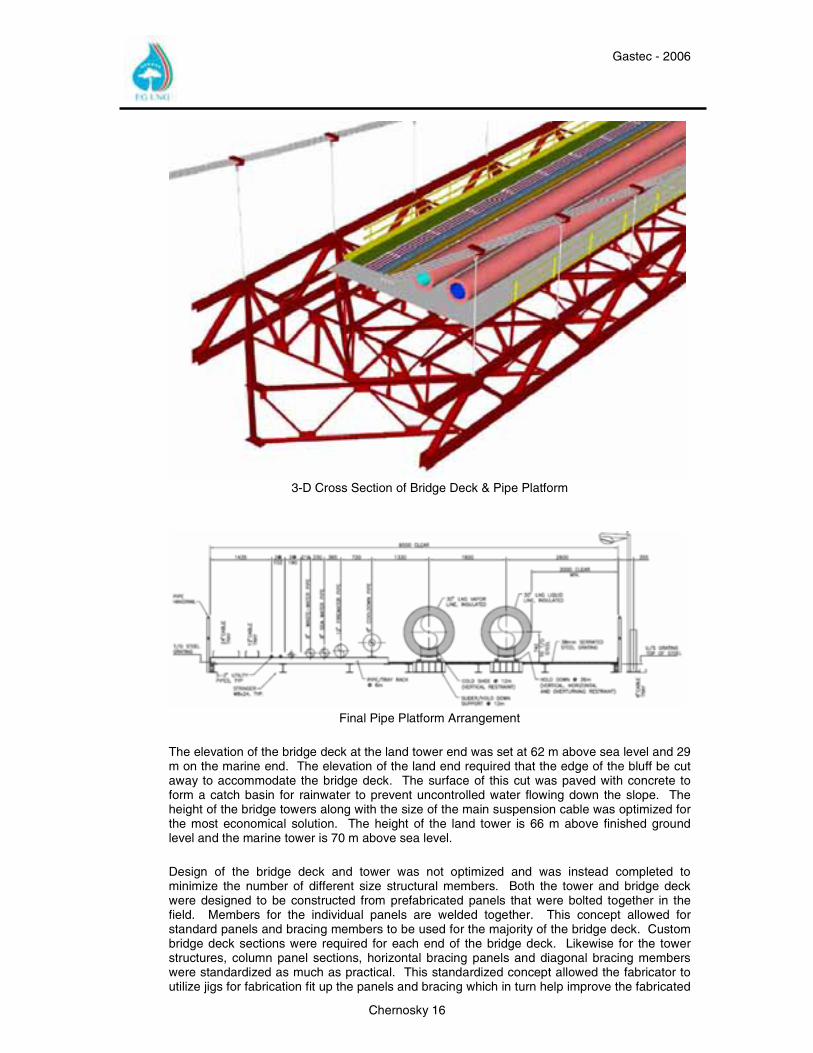
3-D Cross Section of Bridge Deck & Pipe Platform
Final Pipe Platform Arrangement
The elevation of the bridge deck at the land tower end was set at 62 m above sea level and 29 m on the marine end. The elevation of the land end required that the edge of the bluff be cut away to accommodate the bridge deck. The surface of this cut was paved with concrete to form a catch basin for rainwater to prevent uncontrolled water flowing down the slope. The height of the bridge towers along with the size of the main suspension cable was optimized for the most economical solution. The height of the land tower is 66 m above finished ground level and the marine tower is 70 m above sea level. Design of the bridge deck and tower was not optimized and was instead completed to minimize the number of different size structural members. Both the tower and bridge deck were designed to be constructed from prefabricated panels that were bolted together in the field. Members for the individual panels are welded together. This concept allowed for standard panels and bracing members to be used for the majority of the bridge deck. Custom bridge deck sections were required for each end of the bridge deck. Likewise for the tower structures, column panel sections, horizontal bracing panels and diagonal bracing members were standardized as much as practical. This standardized concept allowed the fabricator to utilize jigs for fabrication fit up the panels and bracing which in turn help improve the fabricated
Gastec - 2006
Chernosky 17
dimension control quality. The standard design also sped field erection since many of the panels and members were interchangeable. The concept also reduces the risk of shipping damage as a spare set of standard panels and braces were fabricated and shipped to site in the event of transit damage.
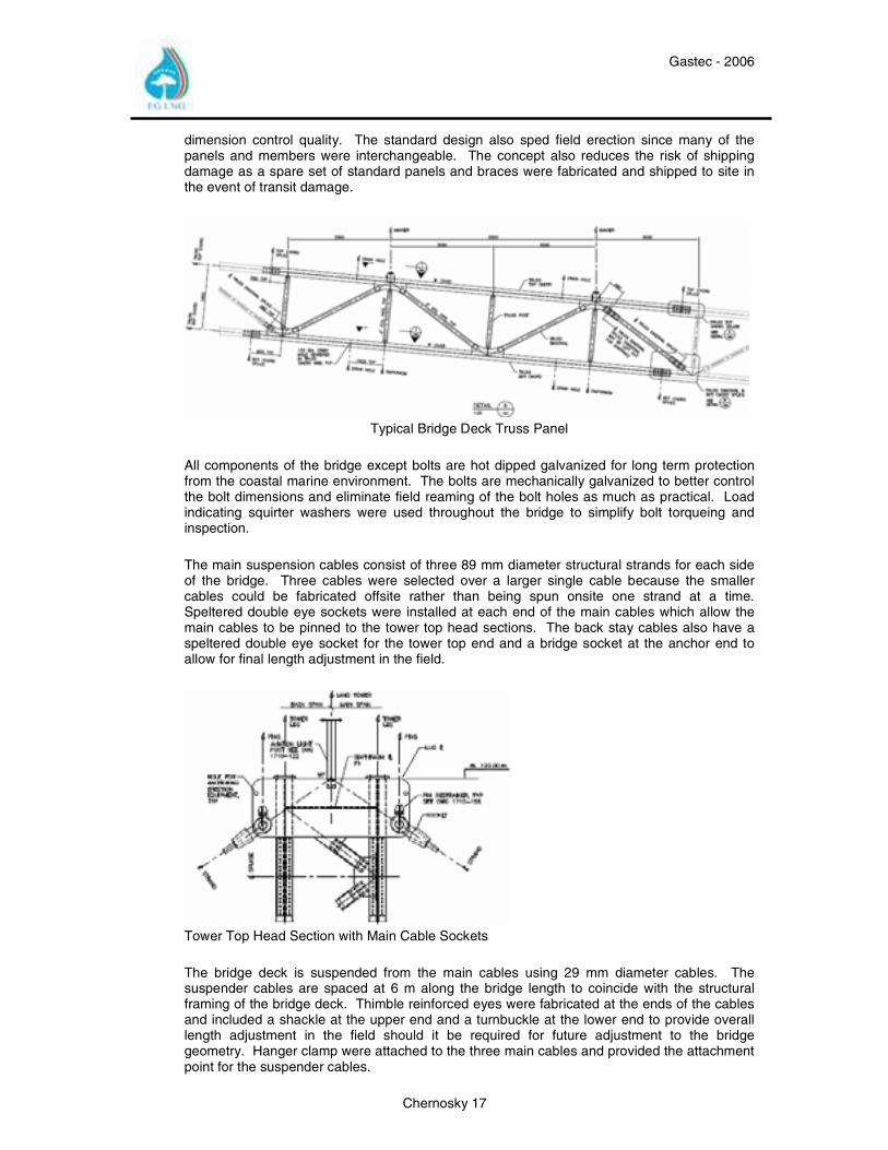
Typical Bridge Deck Truss Panel
All components of the bridge except bolts are hot dipped galvanized for long term protection from the coastal marine environment. The bolts are mechanically galvanized to better control the bolt dimensions and eliminate field reaming of the bolt holes as much as practical. Load indicating squirter washers were used throughout the bridge to simplify bolt torqueing and inspection. The main suspension cables consist of three 89 mm diameter structural strands for each side of the bridge. Three cables were selected over a larger single cable because the smaller cables could be fabricated offsite rather than being spun onsite one strand at a time. Speltered double eye sockets were installed at each end of the main cables which allow the main cables to be pinned to the tower top head sections. The back stay cables also have a speltered double eye socket for the tower top end and a bridge socket at the anchor end to allow for final length adjustment in the field.
Tower Top Head Section with Main Cable Sockets The bridge deck is suspended from the main cables using 29 mm diameter cables. The suspender cables are spaced at 6 m along the bridge length to coincide with the structural framing of the bridge deck. Thimble reinforced eyes were fabricated at the ends of the cables and included a shackle at the upper end and a turnbuckle at the lower end to provide overall length adjustment in the field should it be required for future adjustment to the bridge geometry. Hanger clamp were attached to the three main cables and provided the attachment point for the suspender cables.
Gastec - 2006
Chernosky 18
5.5 Land Foundation Design
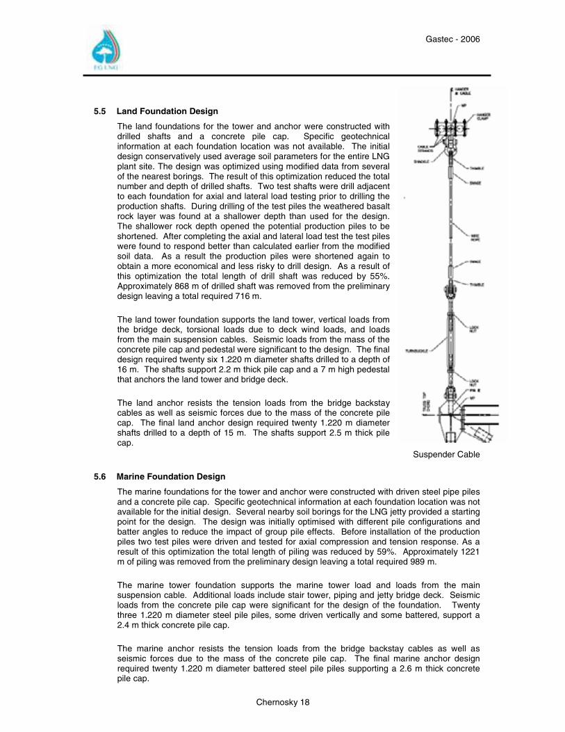
The land foundations for the tower and anchor were constructed with drilled shafts and a concrete pile cap. Specific geotechnical information at each foundation location was not available. The initial design conservatively used average soil parameters for the entire LNG plant site. The design was optimized using modified data from several of the nearest borings. The result of this optimization reduced the total number and depth of drilled shafts. Two test shafts were drill adjacent to each foundation for axial and lateral load testing prior to drilling the production shafts. During drilling of the test piles the weathered basalt rock layer was found at a shallower depth than used for the design. The shallower rock depth opened the potential production piles to be shortened. After completing the axial and lateral load test the test piles were found to respond better than calculated earlier from the modified soil data. As a result the production piles were shortened again to obtain a more economical and less risky to drill design. As a result of this optimization the total length of drill shaft was reduced by 55%. Approximately 868 m of drilled shaft was removed from the preliminary design leaving a total required 716 m. The land tower foundation supports the land tower, vertical loads from the bridge deck, torsional loads due to deck wind loads, and loads from the main suspension cables. Seismic loads from the mass of the concrete pile cap and pedestal were significant to the design. The final design required twenty six 1.220 m diameter shafts drilled to a depth of 16 m. The shafts support 2.2 m thick pile cap and a 7 m high pedestal that anchors the land tower and bridge deck. The land anchor resists the tension loads from the bridge backstay cables as well as seismic forces due to the mass of the concrete pile cap. The final land anchor design required twenty 1.220 m diameter shafts drilled to a depth of 15 m. The shafts support 2.5 m thick pile cap.
Suspender Cable
5.6 Marine Foundation Design
The marine foundations for the tower and anchor were constructed with driven steel pipe piles and a concrete pile cap. Specific geotechnical information at each foundation location was not available for the initial design. Several nearby soil borings for the LNG jetty provided a starting point for the design. The design was initially optimised with different pile configurations and batter angles to reduce the impact of group pile effects. Before installation of the production piles two test piles were driven and tested for axial compression and tension response. As a result of this optimization the total length of piling was reduced by 59%. Approximately 1221 m of piling was removed from the preliminary design leaving a total required 989 m. The marine tower foundation supports the marine tower load and loads from the main suspension cable. Additional loads include stair tower, piping and jetty bridge deck. Seismic loads from the concrete pile cap were significant for the design of the foundation. Twenty three 1.220 m diameter steel pile piles, some driven vertically and some battered, support a 2.4 m thick concrete pile cap. The marine anchor resists the tension loads from the bridge backstay cables as well as seismic forces due to the mass of the concrete pile cap. The final marine anchor design required twenty 1.220 m diameter battered steel pile piles supporting a 2.6 m thick concrete pile cap.
Gastec - 2006
Chernosky 19
5.7 Aerodynamic Design
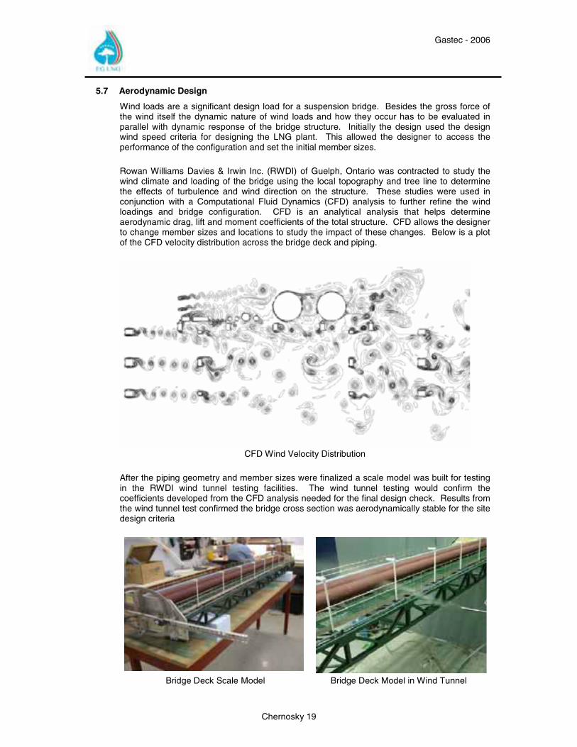
Wind loads are a significant design load for a suspension bridge. Besides the gross force of the wind itself the dynamic nature of wind loads and how they occur has to be evaluated in parallel with dynamic response of the bridge structure. Initially the design used the design wind speed criteria for designing the LNG plant. This allowed the designer to access the performance of the configuration and set the initial member sizes. Rowan Williams Davies & Irwin Inc. (RWDI) of Guelph, Ontario was contracted to study the wind climate and loading of the bridge using the local topography and tree line to determine the effects of turbulence and wind direction on the structure. These studies were used in conjunction with a Computational Fluid Dynamics (CFD) analysis to further refine the wind loadings and bridge configuration. CFD is an analytical analysis that helps determine aerodynamic drag, lift and moment coefficients of the total structure. CFD allows the designer to change member sizes and locations to study the impact of these changes. Below is a plot of the CFD velocity distribution across the bridge deck and piping.
CFD Wind Velocity Distribution
After the piping geometry and member sizes were finalized a scale model was built for testing in the RWDI wind tunnel testing facilities. The wind tunnel testing would confirm the coefficients developed from the CFD analysis needed for the final design check. Results from the wind tunnel test confirmed the bridge cross section was aerodynamically stable for the site design criteria
Bridge Deck Scale Model Bridge Deck Model in Wind Tunnel
Gastec - 2006
Chernosky 20
6.0 Installation Engineering & Design
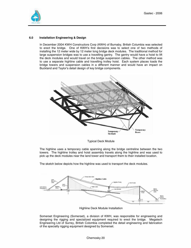
In December 2004 KWH Constructors Corp (KWH) of Burnaby, British Columbia was selected to erect the bridge. One of KWH’s first decisions was to select one of two methods of installing the 12 meter wide by 12 meter long bridge deck modules. The traditional method for large suspension bridges was to use a travelling gantry. The gantry would have a hoist to lift the deck modules and would travel on the bridge suspension cables. The other method was to use a separate highline cable and travelling trolley hoist. Each system places loads the bridge towers and suspension cables in a different manner and would have an impact on Buckland and Taylor’s detail design of key bridge components.
Typical Deck Module The highline uses a temporary cable spanning along the bridge centreline between the two towers. The highline trolley and hoist assembly travels along the highline and was used to pick up the deck modules near the land tower and transport them to their installed location. The sketch below depicts how the highline was used to transport the deck modules.
Highline Deck Module Installation
Somerset Engineering (Somerset), a division of KWH, was responsible for engineering and designing the rigging and specialized equipment required to erect the bridge. Megatech Engineering Ltd of Surrey, British Colombia completed the detail engineering and fabrication of the specialty rigging equipment designed by Somerset.
Gastec - 2006
Chernosky 21
7.0 Fabrication
7.1 Structural Steel
Bechtel awarded the structural steel fabrication package for the suspension bridge to PAX, Inc. in November 2004. Based in Gonzales, Louisiana, PAX also fabricated the majority of the structural steel components for the main plant, was familiar with the project’s quality requirements, and was able to satisfy the aggressive delivery schedule. The suspension bridge required a total quantity of 1,200 tons of fabricated structural steel.
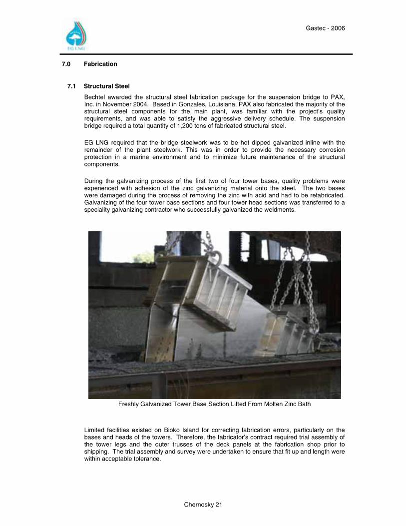
EG LNG required that the bridge steelwork was to be hot dipped galvanized inline with the remainder of the plant steelwork. This was in order to provide the necessary corrosion protection in a marine environment and to minimize future maintenance of the structural components. During the galvanizing process of the first two of four tower bases, quality problems were experienced with adhesion of the zinc galvanizing material onto the steel. The two bases were damaged during the process of removing the zinc with acid and had to be refabricated. Galvanizing of the four tower base sections and four tower head sections was transferred to a speciality galvanizing contractor who successfully galvanized the weldments.
Freshly Galvanized Tower Base Section Lifted From Molten Zinc Bath
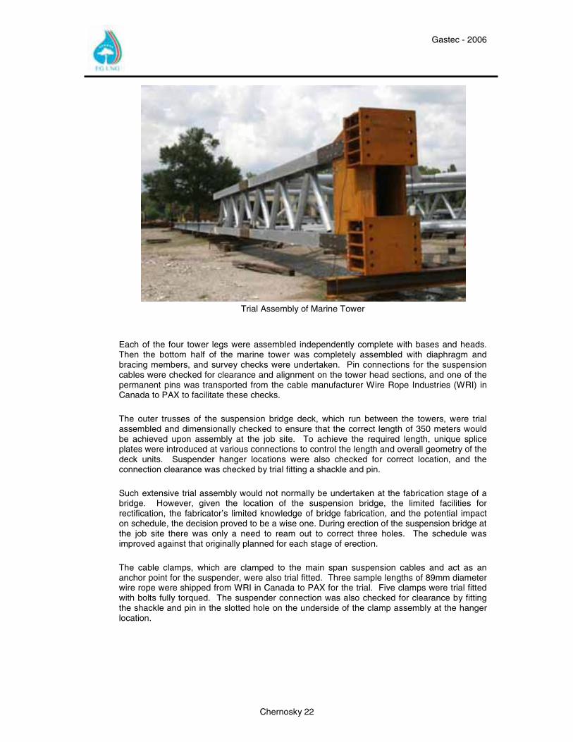
Limited facilities existed on Bioko Island for correcting fabrication errors, particularly on the bases and heads of the towers. Therefore, the fabricator’s contract required trial assembly of the tower legs and the outer trusses of the deck panels at the fabrication shop prior to shipping. The trial assembly and survey were undertaken to ensure that fit up and length were within acceptable tolerance.
Gastec - 2006
Chernosky 22
Trial Assembly of Marine Tower
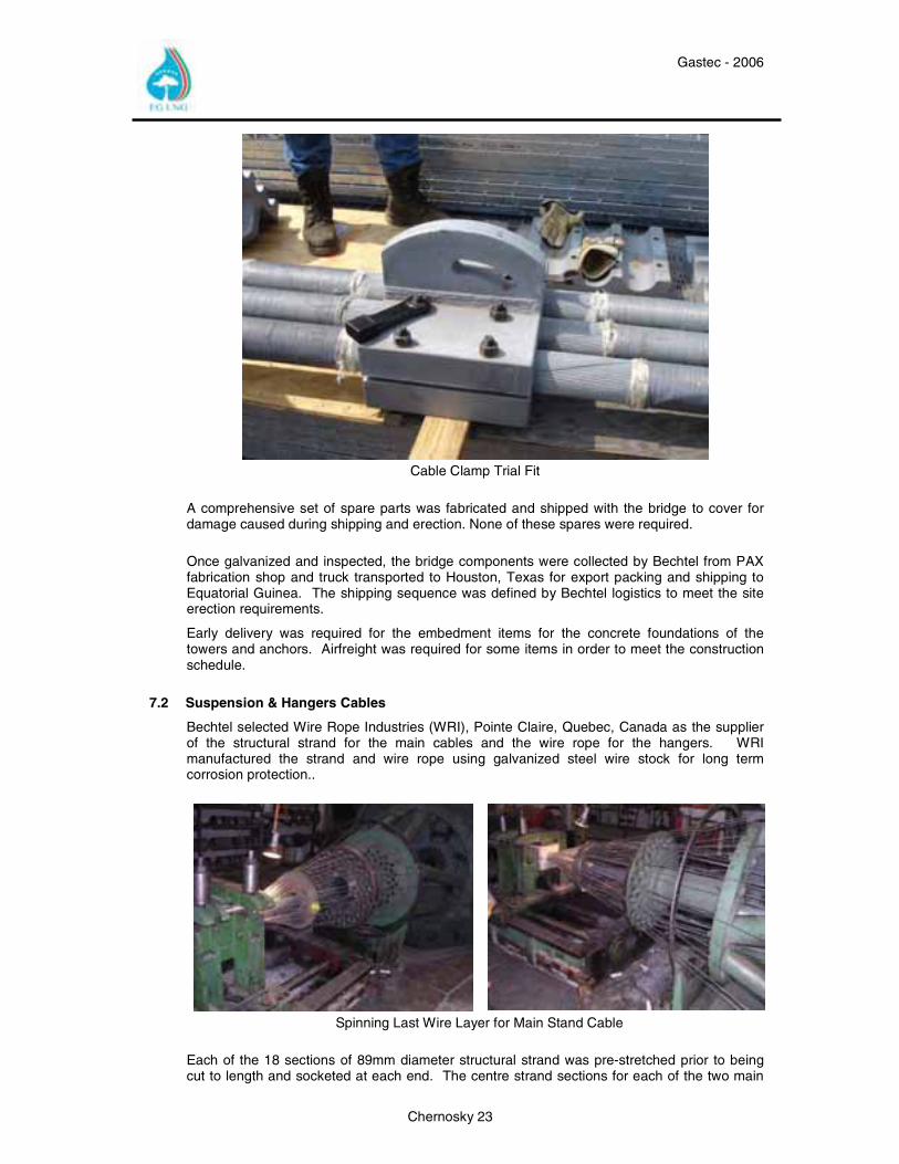
Each of the four tower legs were assembled independently complete with bases and heads. Then the bottom half of the marine tower was completely assembled with diaphragm and bracing members, and survey checks were undertaken. Pin connections for the suspension cables were checked for clearance and alignment on the tower head sections, and one of the permanent pins was transported from the cable manufacturer Wire Rope Industries (WRI) in Canada to PAX to facilitate these checks. The outer trusses of the suspension bridge deck, which run between the towers, were trial assembled and dimensionally checked to ensure that the correct length of 350 meters would be achieved upon assembly at the job site. To achieve the required length, unique splice plates were introduced at various connections to control the length and overall geometry of the deck units. Suspender hanger locations were also checked for correct location, and the connection clearance was checked by trial fitting a shackle and pin. Such extensive trial assembly would not normally be undertaken at the fabrication stage of a bridge. However, given the location of the suspension bridge, the limited facilities for rectification, the fabricator’s limited knowledge of bridge fabrication, and the potential impact on schedule, the decision proved to be a wise one. During erection of the suspension bridge at the job site there was only a need to ream out to correct three holes. The schedule was improved against that originally planned for each stage of erection. The cable clamps, which are clamped to the main span suspension cables and act as an anchor point for the suspender, were also trial fitted. Three sample lengths of 89mm diameter wire rope were shipped from WRI in Canada to PAX for the trial. Five clamps were trial fitted with bolts fully torqued. The suspender connection was also checked for clearance by fitting the shackle and pin in the slotted hole on the underside of the clamp assembly at the hanger location.
Gastec - 2006
Chernosky 23
Cable Clamp Trial Fit
A comprehensive set of spare parts was fabricated and shipped with the bridge to cover for damage caused during shipping and erection. None of these spares were required. Once galvanized and inspected, the bridge components were collected by Bechtel from PAX fabrication shop and truck transported to Houston, Texas for export packing and shipping to Equatorial Guinea. The shipping sequence was defined by Bechtel logistics to meet the site erection requirements.
Early delivery was required for the embedment items for the concrete foundations of the towers and anchors. Airfreight was required for some items in order to meet the construction schedule.
7.2 Suspension & Hangers Cables
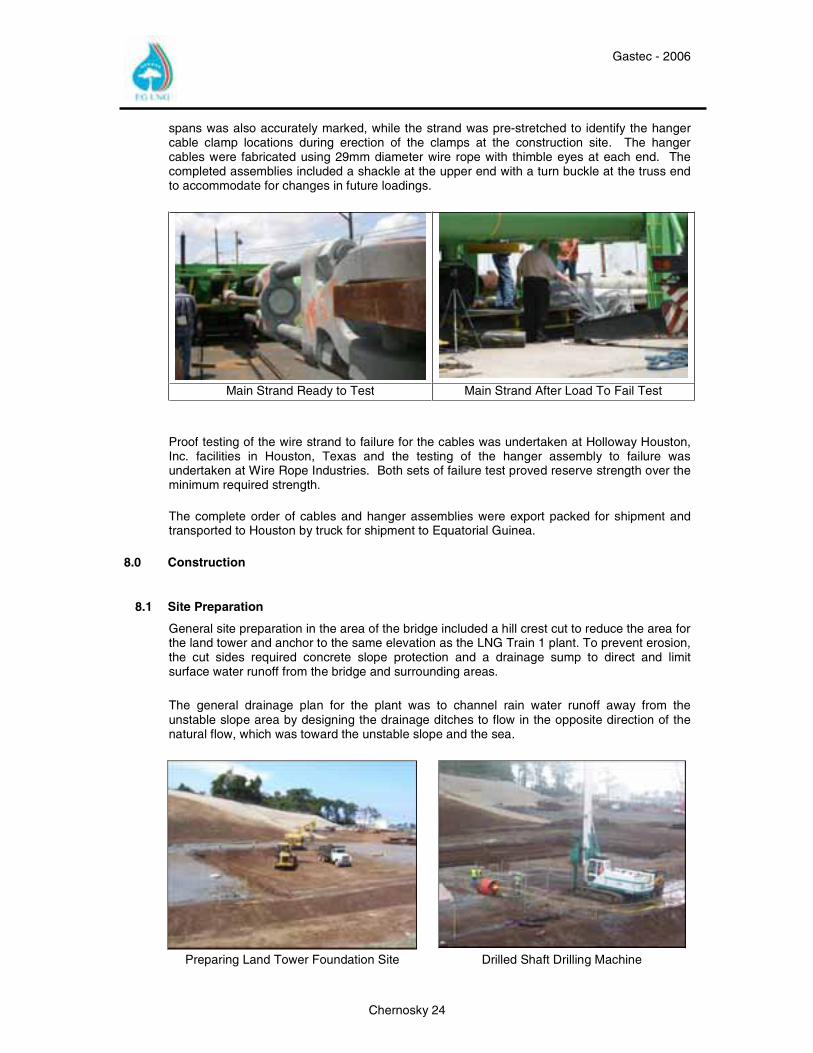
Bechtel selected Wire Rope Industries (WRI), Pointe Claire, Quebec, Canada as the supplier of the structural strand for the main cables and the wire rope for the hangers. WRI manufactured the strand and wire rope using galvanized steel wire stock for long term corrosion protection..
Spinning Last Wire Layer for Main Stand Cable
Each of the 18 sections of 89mm diameter structural strand was pre-stretched prior to being cut to length and socketed at each end. The centre strand sections for each of the two main
Gastec - 2006
Chernosky 24
spans was also accurately marked, while the strand was pre-stretched to identify the hanger cable clamp locations during erection of the clamps at the construction site. The hanger cables were fabricated using 29mm diameter wire rope with thimble eyes at each end. The completed assemblies included a shackle at the upper end with a turn buckle at the truss end to accommodate for changes in future loadings.
Main Strand Ready to Test Main Strand After Load To Fail Test
Proof testing of the wire strand to failure for the cables was undertaken at Holloway Houston, Inc. facilities in Houston, Texas and the testing of the hanger assembly to failure was undertaken at Wire Rope Industries. Both sets of failure test proved reserve strength over the minimum required strength.
The complete order of cables and hanger assemblies were export packed for shipment and transported to Houston by truck for shipment to Equatorial Guinea.
8.0 Construction
8.1 Site Preparation
General site preparation in the area of the bridge included a hill crest cut to reduce the area for the land tower and anchor to the same elevation as the LNG Train 1 plant. To prevent erosion, the cut sides required concrete slope protection and a drainage sump to direct and limit surface water runoff from the bridge and surrounding areas.
The general drainage plan for the plant was to channel rain water runoff away from the unstable slope area by designing the drainage ditches to flow in the opposite direction of the natural flow, which was toward the unstable slope and the sea.
Preparing Land Tower Foundation Site Drilled Shaft Drilling Machine
Gastec - 2006
Chernosky 25
8.2 Land Tower & Anchor Foundation
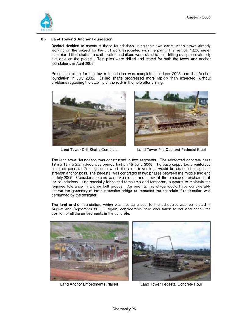
Bechtel decided to construct these foundations using their own construction crews already working on the project for the civil work associated with the plant. The vertical 1.220 meter diameter drilled shafts beneath both foundations were sized to suit drilling equipment already available on the project. Test piles were drilled and tested for both the tower and anchor foundations in April 2005. Production piling for the tower foundation was completed in June 2005 and the Anchor foundation in July 2005. Drilled shafts progressed more rapidly than expected, without problems regarding the stability of the rock in the hole after drilling.
Land Tower Drill Shafts Complete Land Tower Pile Cap and Pedestal Steel
The land tower foundation was constructed in two segments. The reinforced concrete base 18m x 15m x 2.2m deep was poured first on 15 June 2005. The base supported a reinforced concrete pedestal 7m high onto which the steel tower legs would be attached using high strength anchor bolts. The pedestal was concreted in two phases between the middle and end of July 2005. Considerable care was taken to set and check all the embedded anchors in all the foundations using specially fabricated templates and temporary supports to maintain the required tolerance in anchor bolt groups. An error at this stage would have considerably altered the geometry of the suspension bridge or impacted the schedule if rectification was demanded by the designer. The land anchor foundation, which was not as critical to the schedule, was completed in August and September 2005. Again, considerable care was taken to set and check the position of all the embedments in the concrete.
Land Anchor Embedments Placed Land Tower Pedestal Concrete Pour
Gastec - 2006
Chernosky 26
8.3 Marine Tower & Anchor Foundation
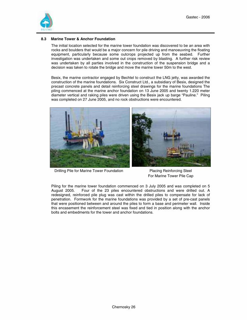
The initial location selected for the marine tower foundation was discovered to be an area with rocks and boulders that would be a major concern for pile driving and manoeuvring the floating equipment, particularly because some outcrops projected up from the seabed. Further investigation was undertaken and some out crops removed by blasting. A further risk review was undertaken by all parties involved in the construction of the suspension bridge and a decision was taken to rotate the bridge and move the marine tower 50m to the west. Besix, the marine contractor engaged by Bechtel to construct the LNG jetty, was awarded the construction of the marine foundations. Six Construct Ltd., a subsidiary of Besix, designed the precast concrete panels and detail reinforcing steel drawings for the marine foundations The piling commenced at the marine anchor foundation on 13 June 2005 and twenty 1.220 meter diameter vertical and raking piles were driven using the Besix jack up barge “Pauline.” Piling was completed on 27 June 2005, and no rock obstructions were encountered.
Drilling Pile for Marine Tower Foundation Placing Reinforcing Steel
For Marine Tower Pile Cap Piling for the marine tower foundation commenced on 3 July 2005 and was completed on 5 August 2005. Four of the 23 piles encountered obstructions and were drilled out. A redesigned, reinforced pile plug was cast within the drilled piles to compensate for lack of penetration. Formwork for the marine foundations was provided by a set of pre-cast panels that were positioned between and around the piles to form a base and perimeter wall. Inside this encasement the reinforcement steel was fixed and tied in position along with the anchor bolts and embedments for the tower and anchor foundations.
Gastec - 2006
Chernosky 27
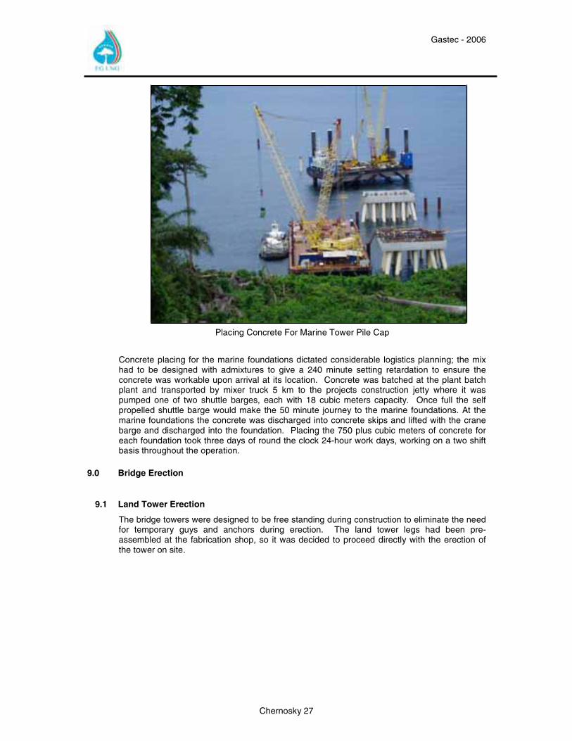
Placing Concrete For Marine Tower Pile Cap
Concrete placing for the marine foundations dictated considerable logistics planning; the mix had to be designed with admixtures to give a 240 minute setting retardation to ensure the concrete was workable upon arrival at its location. Concrete was batched at the plant batch plant and transported by mixer truck 5 km to the projects construction jetty where it was pumped one of two shuttle barges, each with 18 cubic meters capacity. Once full the self propelled shuttle barge would make the 50 minute journey to the marine foundations. At the marine foundations the concrete was discharged into concrete skips and lifted with the crane barge and discharged into the foundation. Placing the 750 plus cubic meters of concrete for each foundation took three days of round the clock 24-hour work days, working on a two shift basis throughout the operation.
9.0 Bridge Erection
9.1 Land Tower Erection
The bridge towers were designed to be free standing during construction to eliminate the need for temporary guys and anchors during erection. The land tower legs had been pre-assembled at the fabrication shop, so it was decided to proceed directly with the erection of the tower on site.
Gastec - 2006
Chernosky 28
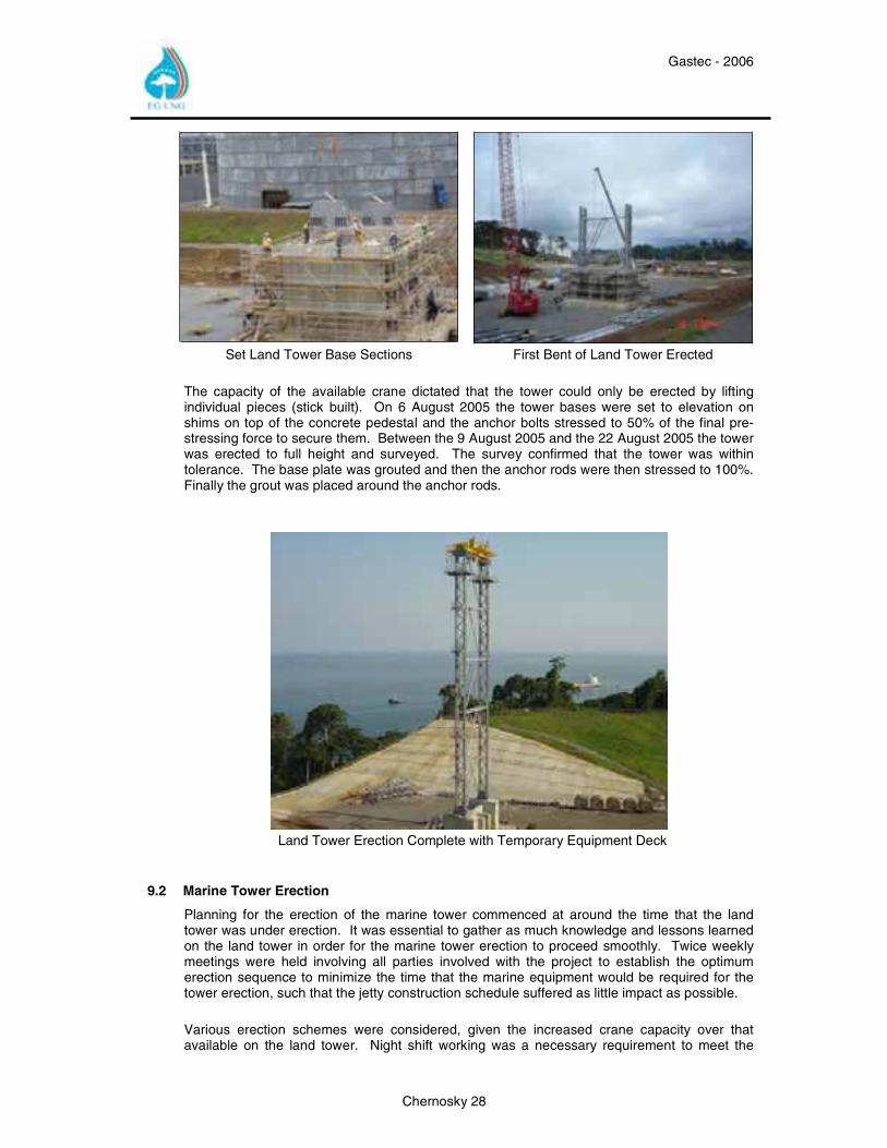
Set Land Tower Base Sections First Bent of Land Tower Erected
The capacity of the available crane dictated that the tower could only be erected by lifting individual pieces (stick built). On 6 August 2005 the tower bases were set to elevation on shims on top of the concrete pedestal and the anchor bolts stressed to 50% of the final pre-stressing force to secure them. Between the 9 August 2005 and the 22 August 2005 the tower was erected to full height and surveyed. The survey confirmed that the tower was within tolerance. The base plate was grouted and then the anchor rods were then stressed to 100%. Finally the grout was placed around the anchor rods.
Land Tower Erection Complete with Temporary Equipment Deck
9.2 Marine Tower Erection
Planning for the erection of the marine tower commenced at around the time that the land tower was under erection. It was essential to gather as much knowledge and lessons learned on the land tower in order for the marine tower erection to proceed smoothly. Twice weekly meetings were held involving all parties involved with the project to establish the optimum erection sequence to minimize the time that the marine equipment would be required for the tower erection, such that the jetty construction schedule suffered as little impact as possible. Various erection schemes were considered, given the increased crane capacity over that available on the land tower. Night shift working was a necessary requirement to meet the
Gastec - 2006
Chernosky 29
imposed three day schedule. Activities were also limited by having to be accomplished safely and with adequate lighting.
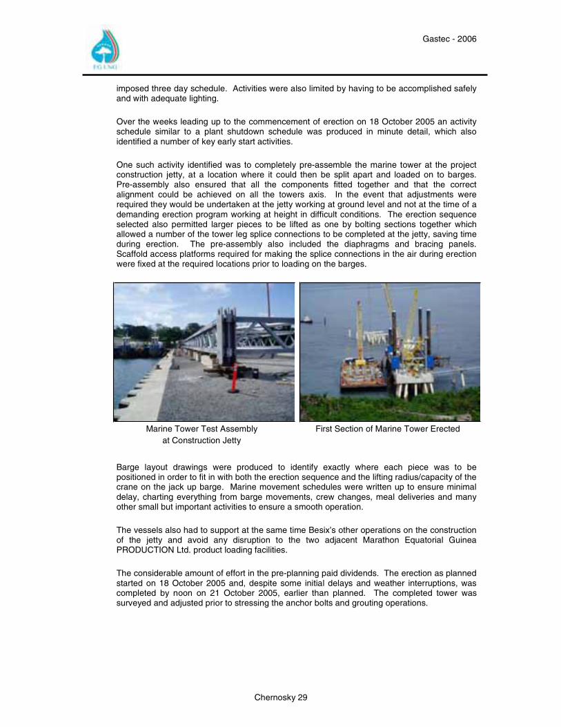
Over the weeks leading up to the commencement of erection on 18 October 2005 an activity schedule similar to a plant shutdown schedule was produced in minute detail, which also identified a number of key early start activities. One such activity identified was to completely pre-assemble the marine tower at the project construction jetty, at a location where it could then be split apart and loaded on to barges. Pre-assembly also ensured that all the components fitted together and that the correct alignment could be achieved on all the towers axis. In the event that adjustments were required they would be undertaken at the jetty working at ground level and not at the time of a demanding erection program working at height in difficult conditions. The erection sequence selected also permitted larger pieces to be lifted as one by bolting sections together which allowed a number of the tower leg splice connections to be completed at the jetty, saving time during erection. The pre-assembly also included the diaphragms and bracing panels. Scaffold access platforms required for making the splice connections in the air during erection were fixed at the required locations prior to loading on the barges.
Marine Tower Test Assembly at Construction Jetty
First Section of Marine Tower Erected
Barge layout drawings were produced to identify exactly where each piece was to be positioned in order to fit in with both the erection sequence and the lifting radius/capacity of the crane on the jack up barge. Marine movement schedules were written up to ensure minimal delay, charting everything from barge movements, crew changes, meal deliveries and many other small but important activities to ensure a smooth operation.
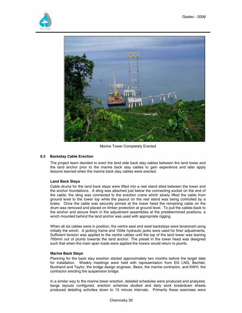
The vessels also had to support at the same time Besix’s other operations on the construction of the jetty and avoid any disruption to the two adjacent Marathon Equatorial Guinea PRODUCTION Ltd. product loading facilities. The considerable amount of effort in the pre-planning paid dividends. The erection as planned started on 18 October 2005 and, despite some initial delays and weather interruptions, was completed by noon on 21 October 2005, earlier than planned. The completed tower was surveyed and adjusted prior to stressing the anchor bolts and grouting operations.
Gastec - 2006
Chernosky 30
Marine Tower Completely Erected
9.3 Backstay Cable Erection
The project team decided to erect the land side back stay cables between the land tower and the land anchor prior to the marine back stay cables to gain experience and later apply lessons learned when the marine back stay cables were erected. Land Back Stays Cable drums for the land back stays were lifted into a reel stand sited between the tower and the anchor foundations. A sling was attached just below the connecting socket on the end of the cable; the sling was connected to the erection crane which slowly lifted the cable from ground level to the tower top while the payout on the reel stand was being controlled by a brake. Once the cable was securely pinned at the tower head the remaining cable on the drum was removed and placed on timber protection at ground level. To pull the cables back to the anchor and secure them in the adjustment assemblies at the predetermined positions, a winch mounted behind the land anchor was used with appropriate rigging.
When all six cables were in position, the centre east and west backstays were tensioned using initially the winch. A jacking frame and 150te hydraulic jacks were used for finer adjustments. Sufficient tension was applied to the centre cables until the top of the land tower was leaning 700mm out of plumb towards the land anchor. The preset in the tower head was designed such that when the main span loads were applied the towers would return to plumb. Marine Back Stays Planning for the back stay erection started approximately two months before the target date for installation. Weekly meetings were held with representation from EG LNG, Bechtel, Buckland and Taylor, the bridge design engineer, Besix, the marine contractor, and KWH, the contractor erecting the suspension bridge. In a similar way to the marine tower erection, detailed schedules were produced and analyzed, barge layouts configured, erection schemes studied and daily work breakdown sheets produced detailing activities down to 15 minute intervals. Primarily these exercises were
Gastec - 2006
Chernosky 31
undertaken to minimize impact to the piling operation being undertaken on the jetty which required the jack up barge Pauline.
One major concern identified during the meetings was how to safely manoeuvre the 50 meter long supply barge, Neptune, into the 70 meter gap between the marine tower foundation and the marine anchor foundation, particularly if there were high sea swells. The final agreed solution was to refit the three spud legs into the barge, to position one end of the barge as near as possible to its final position with the two tug boats and then using the crane on the jack up barge, release one of the spuds and lower it to penetrate the sea bed. With one end fixed the tug boats repositioned and manoeuvred the free end of the barge into position, again using the crane on the jack up barge the remaining two spud legs were lowered to penetrate the sea bed. The back stay operation commenced early morning on 3 December 2005 to take advantage of an early high tide to manoeuvre the jack up barge Pauline into position. The supply barge Neptune was towed from the construction jetty at slack water, having been loaded with the cable drums the day before, and moved into position between the foundations without any incident. Back stay cable erection commenced late in the morning on a two shift arrangement and was completed on the evening of 4 December 2005. The cable drums were lifted into a reel stand on the Neptune barge and lifted to the tower head using the crane on the jack up barge Pauline. Once the top sockets were pinned in position a winch located at the back of the marine anchor was rigged and connected to the lower socket of the cable and the cable pulled into the adjustment assemblies pinned at the marine anchor foundation. To complete the installation at this stage the center east and center west strands were tensioned using winches and jacks to apply a pre-load to the tower 700mm out of plumb towards the marine anchor.
9.4 Main Span Cable Erection
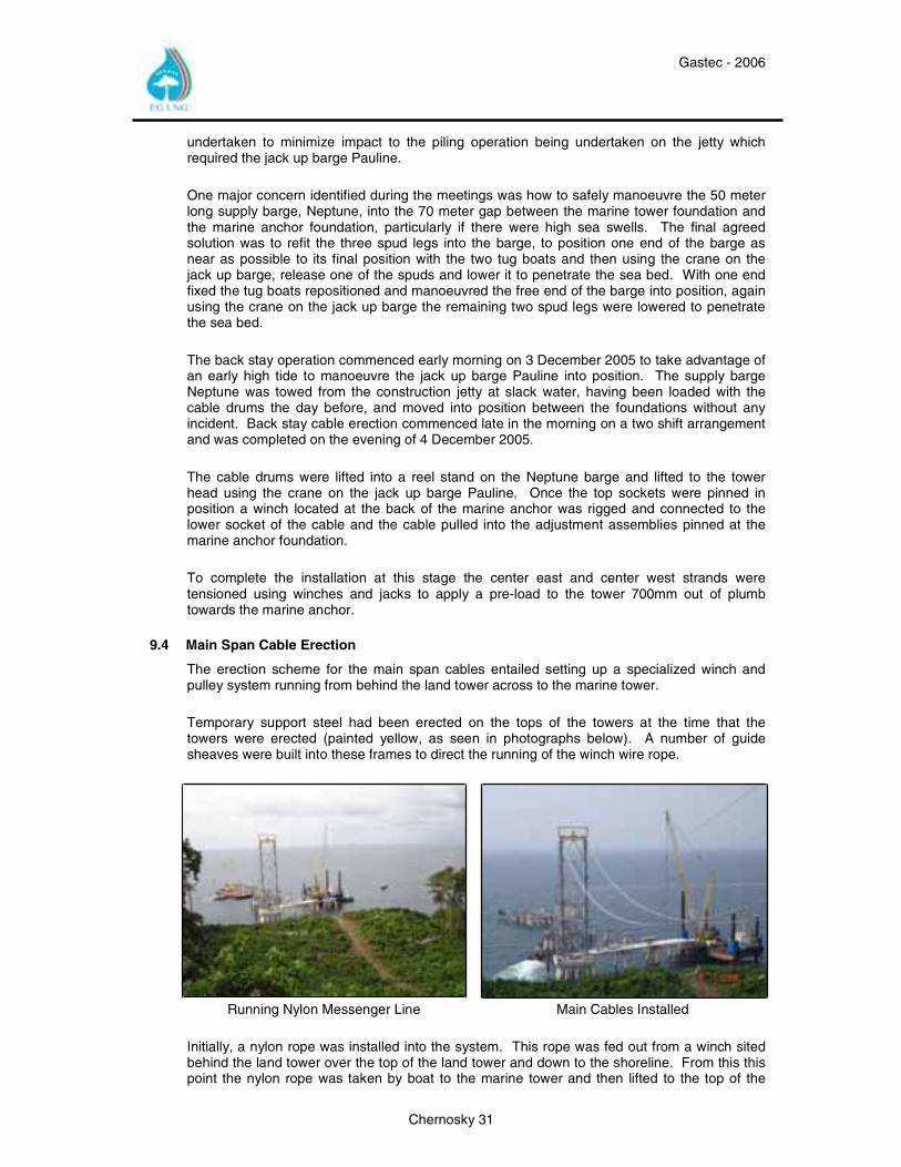
The erection scheme for the main span cables entailed setting up a specialized winch and pulley system running from behind the land tower across to the marine tower.
Temporary support steel had been erected on the tops of the towers at the time that the towers were erected (painted yellow, as seen in photographs below). A number of guide sheaves were built into these frames to direct the running of the winch wire rope.
Running Nylon Messenger Line Main Cables Installed
Initially, a nylon rope was installed into the system. This rope was fed out from a winch sited behind the land tower over the top of the land tower and down to the shoreline. From this this point the nylon rope was taken by boat to the marine tower and then lifted to the top of the
Gastec - 2006
Chernosky 32
marine tower and fed through the sheaves in the temporary steelwork. The rope was then lowered back down to the boat and returned to the shoreline, from where it was taken back to and over the land tower to a second winch. The nylon rope was connected to a small diameter wire rope on the drum of the second winch. Using the first winch the nylon rope was hauled in while the second winch ran out the wire rope until the small diameter wire replaced the nylon rope in the system. The nylon rope was removed from the drum of the first winch and the 5/8” hauling line wound on to the drum and connected to the small diameter wire rope. Using the second winch to haul in the small diameter wire rope and paying out the 5/8” hauling line from the first winch, the required diameter hauling line was put into the system and connected to the second winch. The hauling lines were positioned in plan above the centre lines of both the east and west suspension cable groups.
A cable winder was positioned between the winches and the land anchor foundation. This piece of equipment is used to control the paying out of the main span cables to avoid a run away situation occurring with a cable during installation. The main span cable wrapped on its transportation drum is placed on a reel stand and the cable is the wound off this drum onto the cable winder. The free end of the cable is connected to the hauling line at ground level and, using the winches, is hauled to the top of the land tower with controlled release provided by the cable winder. Once at the land tower the cable has to be fed over the tower on a special sheave. Considerable time was taken on the first cable and many lessons were learned. Once over the tower the cable was hauled at a controlled pace towards the marine tower, at the point in time when the tail end of the cable reached the top of the land tower the operation stopped whilst the tail was fed over the tower into the main span. The connection at the marine tower head was made first and pinned. Then, using the winches, the cable was pulled back to enable the connection to be pinned at the land tower and the cable to be disconnected from the hauling line. This was repeated another five times until all the main span cables were in place
9.5 Track Cables & Highline
The Highline is a cable crane that runs on track cables suspended between the two towers of the bridge and is operated by winches. The Highline system was the erection scheme engineered by KWH the contractor responsible for the bridge’s erection and would be used for the erection of the cable clamps, suspenders, deck units and finally the piping.
Gastec - 2006
Chernosky 33
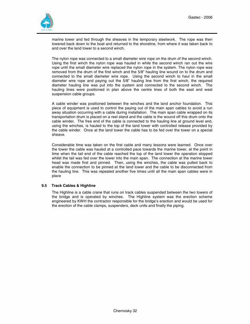
Test Run of Work Platform Used to Install Cable Clamps and Suspender Wires
The two track cables were anchored at the land and marine anchor foundations. Each cable was continuous between these two points and over the towers.
Installation required the cable winder to be positioned behind the land anchor foundation where a track cable would be unreeled from its transportation drum onto the cable winder. The winch rope from a winch positioned on the marine anchor foundation was fed up through the temporary support steelwork on top of the marine tower and then over to the land tower and down to the land anchor foundation. A connection was made to the track cable and the winch at the marine anchor started hauling the track cable across while the cable winder controlled the pay out rate to avoid a runaway situation occurring. The track cable ran in sheaves over the towers was anchored at the marine anchor foundation with tension adjustment at the land anchor foundation.
Having positioned the track cables the trolley and load block was lifted and rigged on to them. The trolley travelled back and forth between the two towers on the track cables and the load block was lowered and raised in such away that components could be lifted and moved into position in the main span of the bridge. The whole system was operated by a winch positioned behind the land tower. The Highline was load tested to 150% of the maximum load across the length of the main span prior to being put into operation
9.6 Cable Clamp & Suspender Erection
An access platform was designed to hang from the Highline, which carried the cable clamps and suspenders; it was also fitted with davits at each end to assist the iron workers during erection. Cable clamps were installed first, the top half of the clamp being position on the cables using the paint marks applied at the factory in Canada. The platform was then raised slightly to offer up the lower half of the clamp and fit and tension the connecting bolts. It took two days to fit all the clamps.
Gastec - 2006
Chernosky 34
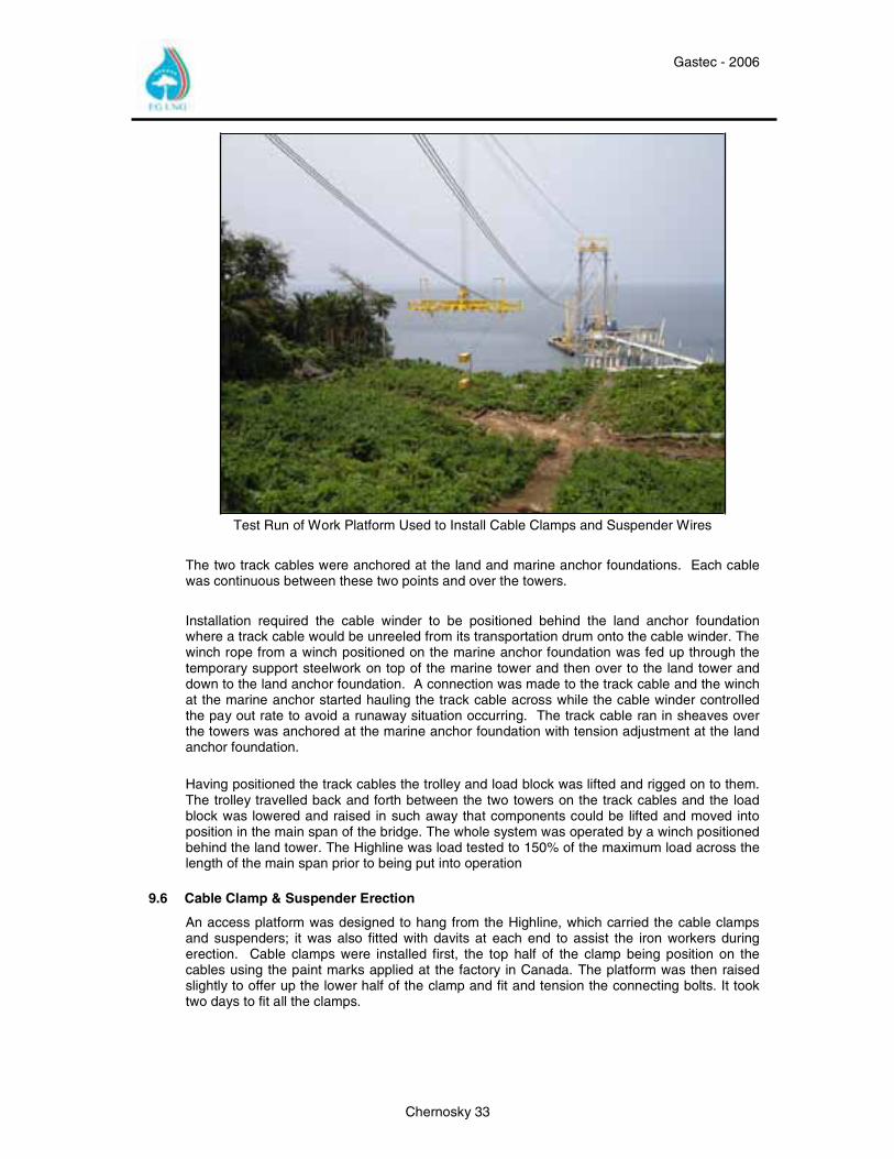
Installing Cable Clamps on Main Strand
The suspenders, which were all preset to length and marked at the factory, were unpacked and laid out in sequence of erection, starting at the marine tower working back towards the land tower. Suspenders were loaded onto the travelling platform, taking into consideration the platform’s load capacity. Once in position at a clamp the suspender would be fitted to the clamp and the platform lowered to pay out carefully the wire rope. Both east and west suspenders were hung at the same time.
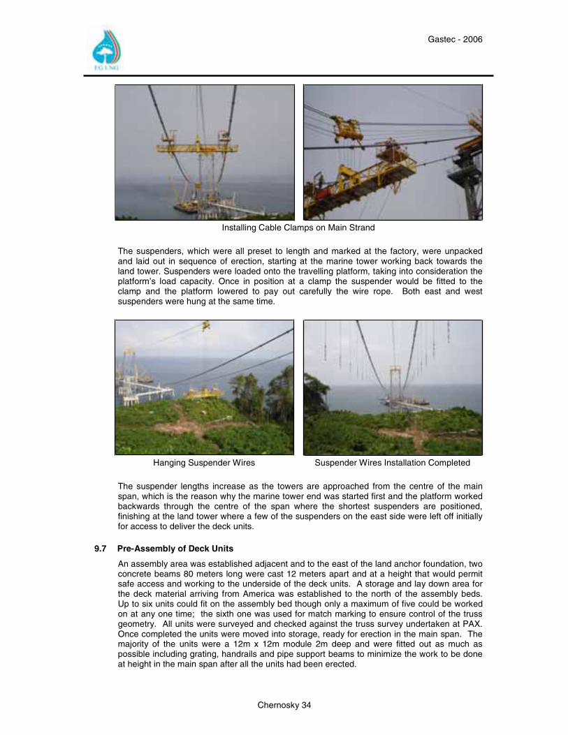
Hanging Suspender Wires Suspender Wires Installation Completed
The suspender lengths increase as the towers are approached from the centre of the main span, which is the reason why the marine tower end was started first and the platform worked backwards through the centre of the span where the shortest suspenders are positioned, finishing at the land tower where a few of the suspenders on the east side were left off initially for access to deliver the deck units.
9.7 Pre-Assembly of Deck Units
An assembly area was established adjacent and to the east of the land anchor foundation, two concrete beams 80 meters long were cast 12 meters apart and at a height that would permit safe access and working to the underside of the deck units. A storage and lay down area for the deck material arriving from America was established to the north of the assembly beds. Up to six units could fit on the assembly bed though only a maximum of five could be worked on at any one time; the sixth one was used for match marking to ensure control of the truss geometry. All units were surveyed and checked against the truss survey undertaken at PAX. Once completed the units were moved into storage, ready for erection in the main span. The majority of the units were a 12m x 12m module 2m deep and were fitted out as much as possible including grating, handrails and pipe support beams to minimize the work to be done at height in the main span after all the units had been erected.
Gastec - 2006
Chernosky 35
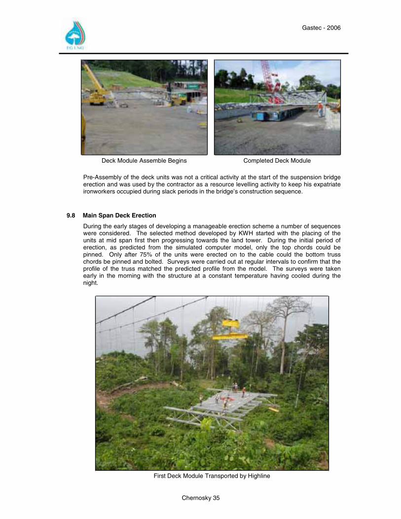
Deck Module Assemble Begins Completed Deck Module
Pre-Assembly of the deck units was not a critical activity at the start of the suspension bridge erection and was used by the contractor as a resource levelling activity to keep his expatriate ironworkers occupied during slack periods in the bridge’s construction sequence.
9.8 Main Span Deck Erection
During the early stages of developing a manageable erection scheme a number of sequences were considered. The selected method developed by KWH started with the placing of the units at mid span first then progressing towards the land tower. During the initial period of erection, as predicted from the simulated computer model, only the top chords could be pinned. Only after 75% of the units were erected on to the cable could the bottom truss chords be pinned and bolted. Surveys were carried out at regular intervals to confirm that the profile of the truss matched the predicted profile from the model. The surveys were taken early in the morning with the structure at a constant temperature having cooled during the night.
First Deck Module Transported by Highline
Gastec - 2006
Chernosky 36
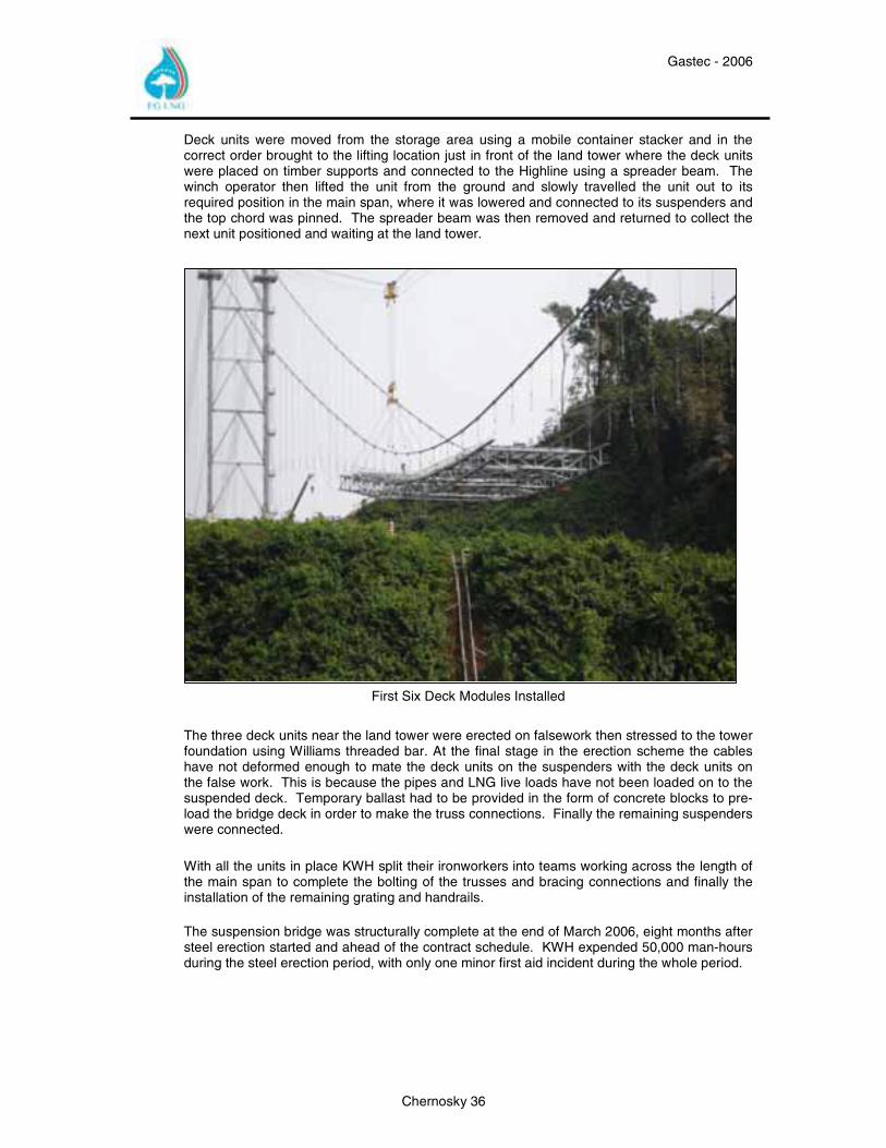
Deck units were moved from the storage area using a mobile container stacker and in the correct order brought to the lifting location just in front of the land tower where the deck units were placed on timber supports and connected to the Highline using a spreader beam. The winch operator then lifted the unit from the ground and slowly travelled the unit out to its required position in the main span, where it was lowered and connected to its suspenders and the top chord was pinned. The spreader beam was then removed and returned to collect the next unit positioned and waiting at the land tower.
First Six Deck Modules Installed
The three deck units near the land tower were erected on falsework then stressed to the tower foundation using Williams threaded bar. At the final stage in the erection scheme the cables have not deformed enough to mate the deck units on the suspenders with the deck units on the false work. This is because the pipes and LNG live loads have not been loaded on to the suspended deck. Temporary ballast had to be provided in the form of concrete blocks to pre-load the bridge deck in order to make the truss connections. Finally the remaining suspenders were connected.
With all the units in place KWH split their ironworkers into teams working across the length of the main span to complete the bolting of the trusses and bracing connections and finally the installation of the remaining grating and handrails. The suspension bridge was structurally complete at the end of March 2006, eight months after steel erection started and ahead of the contract schedule. KWH expended 50,000 man-hours during the steel erection period, with only one minor first aid incident during the whole period.
Gastec - 2006
Chernosky 37
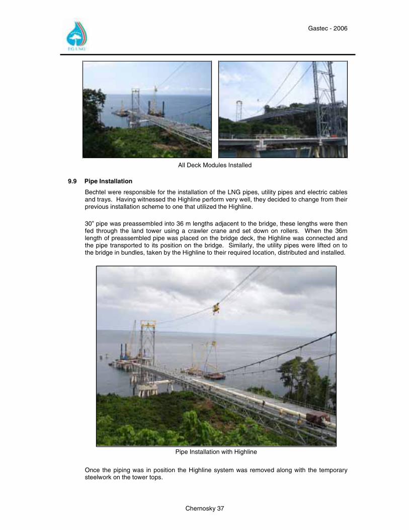
All Deck Modules Installed
9.9 Pipe Installation
Bechtel were responsible for the installation of the LNG pipes, utility pipes and electric cables and trays. Having witnessed the Highline perform very well, they decided to change from their previous installation scheme to one that utilized the Highline. 30” pipe was preassembled into 36 m lengths adjacent to the bridge, these lengths were then fed through the land tower using a crawler crane and set down on rollers. When the 36m length of preassembled pipe was placed on the bridge deck, the Highline was connected and the pipe transported to its position on the bridge. Similarly, the utility pipes were lifted on to the bridge in bundles, taken by the Highline to their required location, distributed and installed.
Pipe Installation with Highline
Once the piping was in position the Highline system was removed along with the temporary steelwork on the tower tops.
Gastec - 2006
Chernosky 38
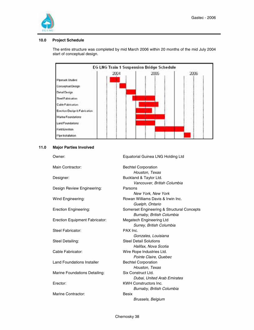
10.0 Project Schedule
The entire structure was completed by mid March 2006 within 20 months of the mid July 2004 start of conceptual design.
11.0 Major Parties Involved
Owner: Equatorial Guinea LNG Holding Ltd Main Contractor: Bechtel Corporation Houston, Texas Designer: Buckland & Taylor Ltd. Vancouver, British Columbia Design Review Engineering: Parsons New York, New York Wind Engineering: Rowan Williams Davis & Irwin Inc. Guelph, Ontario Erection Engineering: Somerset Engineering & Structural Concepts Burnaby, British Columbia Erection Equipment Fabricator: Megatech Engineering Ltd Surrey, British Columbia Steel Fabricator: PAX Inc. Gonzales, Louisiana Steel Detailing: Steel Detail Solutions Halifax, Nova Scotia Cable Fabricator: Wire Rope Industries Ltd. Pointe Claire, Quebec Land Foundations Installer Bechtel Corporation Houston, Texas Marine Foundations Detailing: Six Construct Ltd. Dubai, United Arab Emirates Erector: KWH Constructors Inc. Burnaby, British Columbia Marine Contractor: Besix Brussels, Belgium
Gastec - 2006
Chernosky 39
12.0 About The Authors
Al Chernosky is Engineering Manager for EG Global LNG Services, Ltd in Houston, Texas, USA. He has been involved with the design and procurement of the EG LNG Train 1 Project and is currently assigned as Engineering Manager for the EG LNG Train 2 Project.
Al Chernosky earned a Civil Engineering Bachelors of Science from Texas A&M University in 1975 and worked for McDermott, Inc for 7 years as a offshore structural engineer. He joined Marathon Oil in 1982 working in the
Offshore Technology Division. Since that time he has worked on conventional and frontier production facilities development, design, project management and operations. He is a registered professional engineer in the state of Texas and is a member of ASCE.
Andy Mcghie is engaged by EGLNG based in Equatorial Guinea to oversee the construction of the Suspension Bridge and Marine Facilities for Train 1.
He has worked in the construction industry since 1971 primarily on infrastructure related projects and gained a Higher National Diploma in Civil Engineering in 1975 in the UK.
Prior to joining EGLNG in April 2005 Andy worked for Cleveland Bridge UK Ltd. A world renown Bridge building company. He was Deputy Project Manager and Construction Manager on the Tsing Ma Suspension in Hong Kong, the Worlds Largest suspension bridge. He has also Project Managed Bridge construction projects in Bahrain, Ghana, Saudi Arabia and in the UK.
His marine work experience in the main has been related to Port developments in Abu Dhabi, Muscat and three ports in the UK.