Embed Size (px)
Citation preview
System Parallel ModuleInstallation and Operation Manual
Eaton UPS Accessories


©2014 Eaton CorporationAll Rights Reserved
The contents of this manual are the copyright of the publisher and may not be reproduced (even extracts)unless permission granted. Every care has been taken to ensure the accuracy of the information contained in this manual, but no liability can be accepted for any errors or omission. The right to make design modifications is reserved.
IMPORTANT SAFETY INSTRUCTIONS SAVE THESE INSTRUCTIONSThis manual contains important instructions that you should follow during installation andmaintenance of the SPM. Please read all instructions before operating the equipmentand save this manual for future reference.
Table of Contents
1 InTrodUCTIon . . . . . . . . . . . . . . . . . . . . . . . . . . . . . . . . . . . . . . . . . . . . . . . . . . . . . . . . . . . . . . . . . . . . . . . . . . . . . . . . . . . . . . 11.1 Installation Features . . . . . . . . . . . . . . . . . . . . . . . . . . . . . . . . . . . . . . . . . . . . . . . . . . . . . . . . . . . . . . . . . . . . 11.2 Model Configurations . . . . . . . . . . . . . . . . . . . . . . . . . . . . . . . . . . . . . . . . . . . . . . . . . . . . . . . . . . . . . . . . . . . 21.3 Using This Manual . . . . . . . . . . . . . . . . . . . . . . . . . . . . . . . . . . . . . . . . . . . . . . . . . . . . . . . . . . . . . . . . . . . . . 21.4 Conventions Used in This Manual . . . . . . . . . . . . . . . . . . . . . . . . . . . . . . . . . . . . . . . . . . . . . . . . . . . . . . . . . . 21.5 Symbols, Controls, and Indicators . . . . . . . . . . . . . . . . . . . . . . . . . . . . . . . . . . . . . . . . . . . . . . . . . . . . . . . . . 31.6 For More Information . . . . . . . . . . . . . . . . . . . . . . . . . . . . . . . . . . . . . . . . . . . . . . . . . . . . . . . . . . . . . . . . . . . 31.7 Getting Help . . . . . . . . . . . . . . . . . . . . . . . . . . . . . . . . . . . . . . . . . . . . . . . . . . . . . . . . . . . . . . . . . . . . . . . . . . 3
2 SAfETy WArnIngS . . . . . . . . . . . . . . . . . . . . . . . . . . . . . . . . . . . . . . . . . . . . . . . . . . . . . . . . . . . . . . . . . . . . . . . . . . . . . . . . . . 4
3 InSTAllATIon PlAn And UnPACkIng . . . . . . . . . . . . . . . . . . . . . . . . . . . . . . . . . . . . . . . . . . . . . . . . . . . . . . . . . . . . . . . . . 53.1 Creating an Installation Plan . . . . . . . . . . . . . . . . . . . . . . . . . . . . . . . . . . . . . . . . . . . . . . . . . . . . . . . . . . . . . . 53.2 Preparing the Site . . . . . . . . . . . . . . . . . . . . . . . . . . . . . . . . . . . . . . . . . . . . . . . . . . . . . . . . . . . . . . . . . . . . . . 5
3.2.1 Environmental and Installation Considerations . . . . . . . . . . . . . . . . . . . . . . . . . . . . . . . . . . . . . . . . . . . 63.2.2 SPM Wiring Preparation . . . . . . . . . . . . . . . . . . . . . . . . . . . . . . . . . . . . . . . . . . . . . . . . . . . . . . . . . . . . 9
3.3 Inspecting and Unpacking the SPM . . . . . . . . . . . . . . . . . . . . . . . . . . . . . . . . . . . . . . . . . . . . . . . . . . . . . . . . 113.4 Breaker Location . . . . . . . . . . . . . . . . . . . . . . . . . . . . . . . . . . . . . . . . . . . . . . . . . . . . . . . . . . . . . . . . . . . . . . 12
4 InSTAllATIon . . . . . . . . . . . . . . . . . . . . . . . . . . . . . . . . . . . . . . . . . . . . . . . . . . . . . . . . . . . . . . . . . . . . . . . . . . . . . . . . . . . . . . . 134.1 Preliminary Installation Information . . . . . . . . . . . . . . . . . . . . . . . . . . . . . . . . . . . . . . . . . . . . . . . . . . . . . . . . 134.2 Unloading the SPM Cabinet from the Pallet . . . . . . . . . . . . . . . . . . . . . . . . . . . . . . . . . . . . . . . . . . . . . . . . . . 134.3 External Power Cables Connecting. . . . . . . . . . . . . . . . . . . . . . . . . . . . . . . . . . . . . . . . . . . . . . . . . . . . . . . . . 154.4 External Signaling Cables Connecting . . . . . . . . . . . . . . . . . . . . . . . . . . . . . . . . . . . . . . . . . . . . . . . . . . . . . . 154.5 Initial Startup . . . . . . . . . . . . . . . . . . . . . . . . . . . . . . . . . . . . . . . . . . . . . . . . . . . . . . . . . . . . . . . . . . . . . . . . . 184.6 Completing the Installation Checklist . . . . . . . . . . . . . . . . . . . . . . . . . . . . . . . . . . . . . . . . . . . . . . . . . . . . . . . 18
5 onElInES And SChEmATICS . . . . . . . . . . . . . . . . . . . . . . . . . . . . . . . . . . . . . . . . . . . . . . . . . . . . . . . . . . . . . . . . . . . . . . . . . 205.1 Schematics . . . . . . . . . . . . . . . . . . . . . . . . . . . . . . . . . . . . . . . . . . . . . . . . . . . . . . . . . . . . . . . . . . . . . . . . . . . 20
6 mAInTEnAnCE . . . . . . . . . . . . . . . . . . . . . . . . . . . . . . . . . . . . . . . . . . . . . . . . . . . . . . . . . . . . . . . . . . . . . . . . . . . . . . . . . . . . . . 216.1 Important Safety Instructions . . . . . . . . . . . . . . . . . . . . . . . . . . . . . . . . . . . . . . . . . . . . . . . . . . . . . . . . . . . . . 216.2 Performing Preventive Maintenance . . . . . . . . . . . . . . . . . . . . . . . . . . . . . . . . . . . . . . . . . . . . . . . . . . . . . . . 21
6.2.1 DAILY Maintenance . . . . . . . . . . . . . . . . . . . . . . . . . . . . . . . . . . . . . . . . . . . . . . . . . . . . . . . . . . . . . . . 216.2.2 PERIODIC Maintenance . . . . . . . . . . . . . . . . . . . . . . . . . . . . . . . . . . . . . . . . . . . . . . . . . . . . . . . . . . . . 216.2.3 ANNUAL Maintenance . . . . . . . . . . . . . . . . . . . . . . . . . . . . . . . . . . . . . . . . . . . . . . . . . . . . . . . . . . . . . 216.2.4 BATTERY Maintenance . . . . . . . . . . . . . . . . . . . . . . . . . . . . . . . . . . . . . . . . . . . . . . . . . . . . . . . . . . . . . 21
6.3 Maintenance Training . . . . . . . . . . . . . . . . . . . . . . . . . . . . . . . . . . . . . . . . . . . . . . . . . . . . . . . . . . . . . . . . . . . 21
7 ProdUCT SPECIfICATIonS . . . . . . . . . . . . . . . . . . . . . . . . . . . . . . . . . . . . . . . . . . . . . . . . . . . . . . . . . . . . . . . . . . . . . . . . . . . . 227.1 Specifications . . . . . . . . . . . . . . . . . . . . . . . . . . . . . . . . . . . . . . . . . . . . . . . . . . . . . . . . . . . . . . . . . . . . . . . . . 22
7.1.1 Electrical Specifications . . . . . . . . . . . . . . . . . . . . . . . . . . . . . . . . . . . . . . . . . . . . . . . . . . . . . . . . . . . . 227.1.2 Environmental Specifications . . . . . . . . . . . . . . . . . . . . . . . . . . . . . . . . . . . . . . . . . . . . . . . . . . . . . . . . 22
list of figures
Figure 1-1. Eaton System Parallel Module . . . . . . . . . . . . . . . . . . . . . . . . . . . . . . . . . . . . . . . . . . . . . . . . . . . . . . . . . . . . 1Figure 1-2. Eaton System Parallel Module and UPS(93E as example). . . . . . . . . . . . . . . . . . . . . . . . . . . . . . . . . . . . . . . . 2Figure 3-1. SPM Cabinet Dimensions(Front, Right and Rear Views) . . . . . . . . . . . . . . . . . . . . . . . . . . . . . . . . . . . . . . . . . 7Figure 3-2. SPM Cabinet Dimensions (Top and Bottom Views) . . . . . . . . . . . . . . . . . . . . . . . . . . . . . . . . . . . . . . . . . . . . . 7Figure 3-3. SPM Cabinet as Shipped on Pallet (wood container removed) . . . . . . . . . . . . . . . . . . . . . . . . . . . . . . . . . . . . 12Figure 3-4. Breaker Location . . . . . . . . . . . . . . . . . . . . . . . . . . . . . . . . . . . . . . . . . . . . . . . . . . . . . . . . . . . . . . . . . . . . . . 12Figure 4-1. Removing the Front Shipping Bracket . . . . . . . . . . . . . . . . . . . . . . . . . . . . . . . . . . . . . . . . . . . . . . . . . . . . . . . 14Figure 4-2. Attaching the Ramp to the Pallet . . . . . . . . . . . . . . . . . . . . . . . . . . . . . . . . . . . . . . . . . . . . . . . . . . . . . . . . . . 14Figure 4-3. Removing the Rear Shipping Bracket . . . . . . . . . . . . . . . . . . . . . . . . . . . . . . . . . . . . . . . . . . . . . . . . . . . . . . . 14Figure 4-4. Rolling the Cabinet Down the Ramp . . . . . . . . . . . . . . . . . . . . . . . . . . . . . . . . . . . . . . . . . . . . . . . . . . . . . . . . 14Figure 4-5. Power Terminal Locations . . . . . . . . . . . . . . . . . . . . . . . . . . . . . . . . . . . . . . . . . . . . . . . . . . . . . . . . . . . . . . . . 16Figure 4-6. Power and Signal Terminal Locations . . . . . . . . . . . . . . . . . . . . . . . . . . . . . . . . . . . . . . . . . . . . . . . . . . . . . . . 17Figure 5-1. SPM Schematics . . . . . . . . . . . . . . . . . . . . . . . . . . . . . . . . . . . . . . . . . . . . . . . . . . . . . . . . . . . . . . . . . . . . . . 20

list of Tables
Table 3-1. SPM Cabinet Weights . . . . . . . . . . . . . . . . . . . . . . . . . . . . . . . . . . . . . . . . . . . . . . . . . . . . . . . . . . . . . . . . . . 6Table 3-2. SPM Cabinet Clearances . . . . . . . . . . . . . . . . . . . . . . . . . . . . . . . . . . . . . . . . . . . . . . . . . . . . . . . . . . . . . . . . 6Table 3-3. External Power Wiring Requirements for EBCB . . . . . . . . . . . . . . . . . . . . . . . . . . . . . . . . . . . . . . . . . . . . . . . 9
1
System Parallel Module
Chapter 1 Introduction
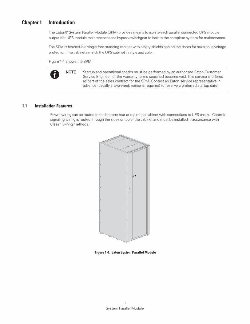
The Eaton® System Parallel Module (SPM) provides means to isolate each parallel connected UPS module output (for UPS module maintenance) and bypass switchgear to isolate the complete system for maintenance.
The SPM is housed in a single free-standing cabinet with safety shields behind the doors for hazardous voltage protection. The cabinets match the UPS cabinet in style and color.
Figure 1-1 shows the SPM.
Startup and operational checks must be performed by an authorized Eaton Customer Service Engineer, or the warranty terms specified become void. This service is offered as part of the sales contract for the SPM. Contact an Eaton service representative in advance (usually a two-week notice is required) to reserve a preferred startup date.
NOTE
Power wiring can be routed to the bottom/ rear or top of the cabinet with connections to UPS easily. Control/signaling wiring is routed through the sides or top of the cabinet and must be installed in accordance with Class 1 wiring methods.
1 .1 Installation features
figure 1-1 . Eaton System Parallel module
2
System Parallel Module
1 .2 model Configurations
1 .3 Using This manualThis manual describes how to install the SPM and is divided into chapters. Read and understand the procedures described to ensure trouble-free installation and operation.
Read through each procedure before beginning the procedure. Perform only those procedures that apply to the SPM being installed or operated.
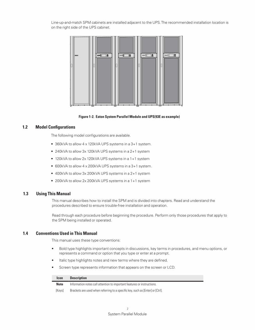
Line-up-and-match SPM cabinets are installed adjacent to the UPS. The recommended installation location is on the right side of the UPS cabinet.
The following model configurations are available.
• 360kVA to allow 4 x 120kVA UPS systems in a 3+1 system.
• 240kVA to allow 3x 120kVA UPS systems in a 2+1 system
• 120kVA to allow 2x 120kVA UPS systems in a 1+1 system
• 600kVA to allow 4 x 200kVA UPS systems in a 3+1 system.
• 400kVA to allow 3x 200kVA UPS systems in a 2+1 system
• 200kVA to allow 2x 200kVA UPS systems in a 1+1 system
1 .4 Conventions Used in This manualThis manual uses these type conventions:
• Bold type highlights important concepts in discussions, key terms in procedures, and menu options, or represents a command or option that you type or enter at a prompt.
• Italic type highlights notes and new terms where they are defined.
• Screen type represents information that appears on the screen or LCD.
Icon description
note Information notes call attention to important features or instructions.
[Keys] Brackets are used when referring to a specific key, such as [Enter] or [Ctrl].
figure 1-2 . Eaton System Parallel module and UPS(93E as example)
3
System Parallel Module
In this manual, the term UPS refers only to the UPS cabinet and its internal elements. The term UPS system refers to the entire power protection system – the UPS cabinet, SPM system, and options or accessories installed.
The term line-up-and-match refers to accessory cabinets that are physically located adjacent to the UPS. The term standalone refers to accessory cabinets that are located separate from the UPS.
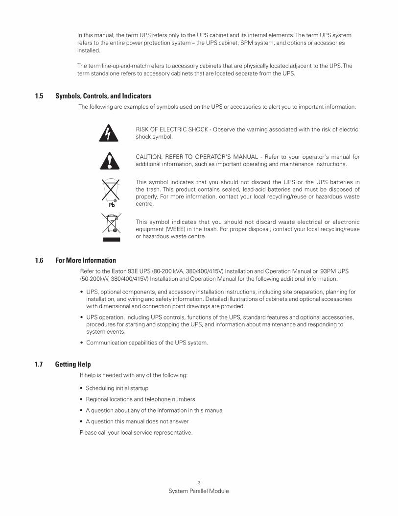
1 .5 Symbols, Controls, and IndicatorsThe following are examples of symbols used on the UPS or accessories to alert you to important information:
RISK OF ELECTRIC SHOCK - Observe the warning associated with the risk of electric shock symbol.
CAUTION: REFER TO OPERATOR'S MANUAL - Refer to your operator's manual for additional information, such as important operating and maintenance instructions.
This symbol indicates that you should not discard the UPS or the UPS batteries in the trash. This product contains sealed, lead-acid batteries and must be disposed of properly. For more information, contact your local recycling/reuse or hazardous waste centre.
This symbol indicates that you should not discard waste electrical or electronic equipment (WEEE) in the trash. For proper disposal, contact your local recycling/reuse or hazardous waste centre.
1 .6 for more InformationRefer to the Eaton 93E UPS (80-200 kVA, 380/400/415V) Installation and Operation Manual or 93PM UPS (50-200kW, 380/400/415V) Installation and Operation Manual for the following additional information:
• UPS, optional components, and accessory installation instructions, including site preparation, planning for installation, and wiring and safety information. Detailed illustrations of cabinets and optional accessories with dimensional and connection point drawings are provided.
• UPS operation, including UPS controls, functions of the UPS, standard features and optional accessories, procedures for starting and stopping the UPS, and information about maintenance and responding to system events.
• Communication capabilities of the UPS system.
1 .7 getting helpIf help is needed with any of the following:
• Scheduling initial startup
• Regional locations and telephone numbers
• A question about any of the information in this manual
• A question this manual does not answer
Please call your local service representative.
4
System Parallel Module
Chapter 2 Safety Warnings
IMPORTANT SAFETY INSTRUCTIONS SAVE THESE INSTRUCTIONSThis manual contains important instructions that should be followed during installation and maintenance of the SPM. Read all instructions before operating the equipment and save this manual for future reference.
The SPM are designed for industrial or computer room applications with UPS, and contains safety shields behind the door and front panels. However, any installation and operations should be handled with appropriate care.
DANGER
The Accessories may contain LETHAL VOLTAGES. All repairs and service should be performed by AUTHORISED SERVICE PERSONNEL ONLY.
WARNING
• The terminals may carry live voltage even when the Accessory is connected to UPS.
• To reduce the risk of fire or electric shock, install the SPM in a temperature and humidity controlled, indoor environment, free of conductive contaminants. Ambient temperature must not exceed 40°C (104°F). Do not operate near water or excessive humidity (95% maximum).
• As a result of the connected loads high leakage current is possible. Connection to earth ground is required for safety and proper product operation. Do not check Accessory or UPS operation by any action that includes removal of the earth (ground) connection with loads attached.
• Ensure all power is disconnected before performing installation or service.
• ELECTRIC ENERGY HAZARD. Do not attempt to alter any Accessory, UPS or battery wiring or connectors. Attempting to alter wiring can cause injury.
• Installation or service should be performed by qualified service personnel knowledgeable of SPM and required precautions. Keep unauthorized personnel away from equipment. Consider all warnings, cautions, and notes before installing or servicing equipment. DO NOT DISCONNECT the batteries while the UPS is in Battery mode.
• See installation instructions before connecting to the supply.
• Determine if the battery is inadvertently grounded. If it is, remove the source of the ground.
• Contacting any part of a grounded battery can cause a risk of electric shock. An electric shock is less likely if you disconnect the grounding connection before you work on the batteries.
• Keep the SPM cabinet doors closed and front panels installed to protect personnel from dangerous voltages inside the unit.
• The operating environment should be maintained within the parameters stated in this manual.
• Keep surroundings uncluttered, clean, and free from excess moisture.
• Observe all DANGER, CAUTION, and WARNING notices affixed to the inside and outside of the equipment.
CAUTION
5
System Parallel Module
Chapter 3 Installation Plan and Unpacking
Use the following basic sequence of steps to install the System Parallel Module
1. Create an installation plan.
2. Prepare your site for the SPM.
3. Inspect and unpack the SPM.
4. Unload and install the SPM, and wire the system.
5. Complete the Installation Checklist.
6. Have authorized service personnel perform preliminary operational checks and start up the system.
3 .1 Creating an Installation Plan
Before installing the SPM, read and understand how this manual applies to the system being installed. Use the procedures and illustrations in this section to create a logical plan for installing the SPM. This section contains the following information:
• Physical features and requirements, including dimensions
• Power wiring installation notes
• Location of conduit and wire entry landing plates
• Location of power terminals
Startup and operational checks for parallel systems or installations with accessory cabinets must be performed by an authorized Eaton Customer Service Engineer, or the warranty terms may become void. This service is offered as part of the sales contract for the UPS. Contact an Eaton service representative in advance (usually a two-week notice is required) to reserve a preferred startup date.
3 .2 Preparing the Site
Similar with the UPS, the SPM installation site should meet the environmental parameters outlined in this manual. If the UPS is to be operated at an altitude higher than 1000m (3300 ft.), contact an Eaton service representative for important information about high altitude operation. The operating environment must meet the weight, clearance, and environmental requirements specified.
NOTE
CAUTION
It must be ensured that no line input source can accidentally be connected to the SPM during the SPM installation.
WARNING
• Installation may only be carried out by qualified technicians and in conformity with the applicable safety standards.
• The SPM is not suitable for IT or corner-earthed power distribution systems.
6
System Parallel Module
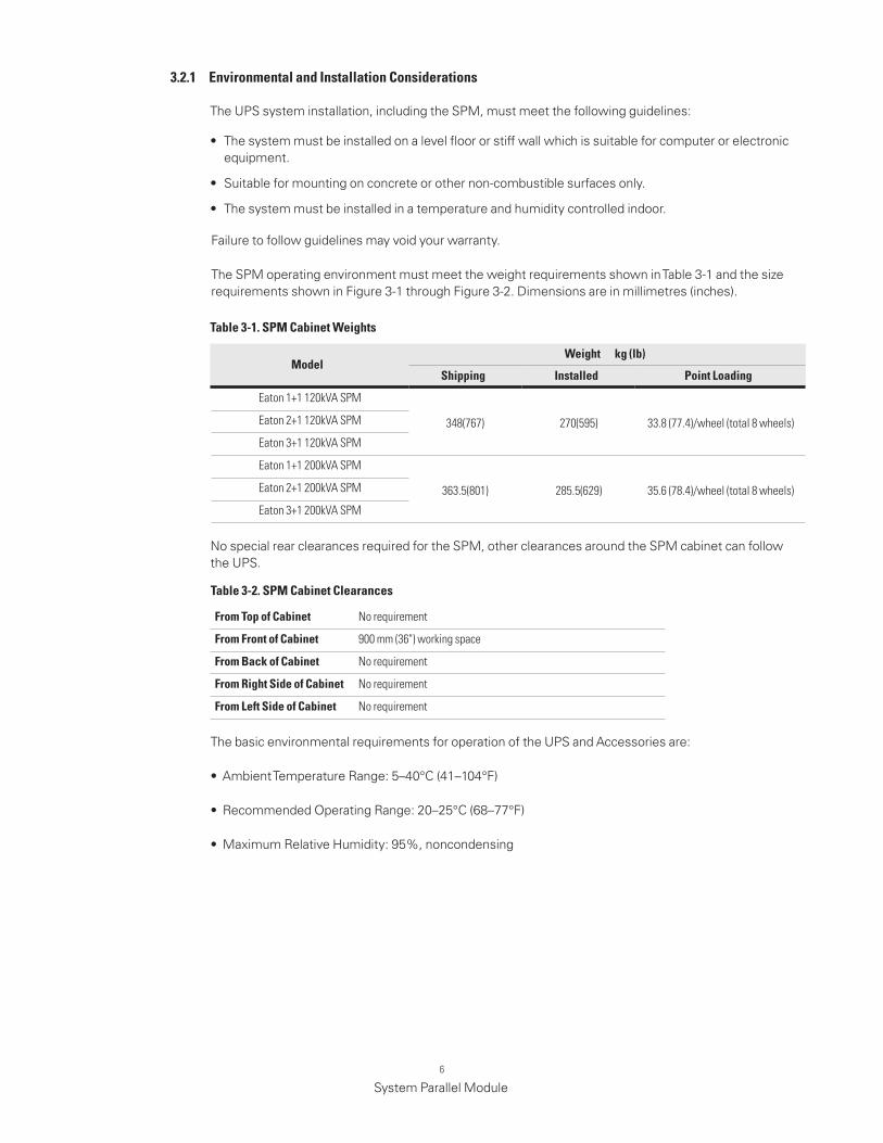
3 .2 .1 Environmental and Installation Considerations
The UPS system installation, including the SPM, must meet the following guidelines:
• The system must be installed on a level floor or stiff wall which is suitable for computer or electronic equipment.
• Suitable for mounting on concrete or other non-combustible surfaces only.
• The system must be installed in a temperature and humidity controlled indoor.
Failure to follow guidelines may void your warranty.
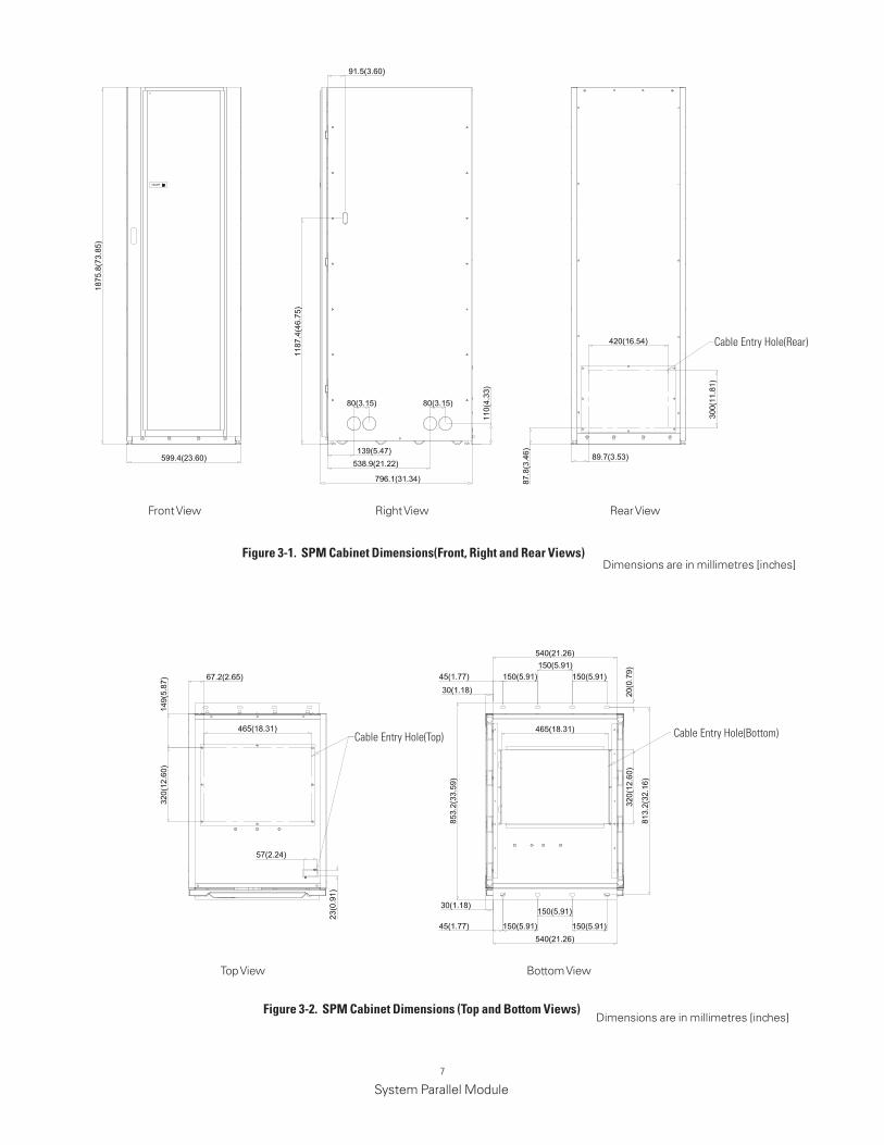
The SPM operating environment must meet the weight requirements shown in Table 3-1 and the size requirements shown in Figure 3-1 through Figure 3-2. Dimensions are in millimetres (inches).
No special rear clearances required for the SPM, other clearances around the SPM cabinet can follow the UPS.
The basic environmental requirements for operation of the UPS and Accessories are:
•AmbientTemperatureRange:5–40°C(41–104°F)
•RecommendedOperatingRange:20–25°C(68–77°F)
•MaximumRelativeHumidity:95%,noncondensing
Table 3-1 . SPm Cabinet Weights
Eaton 1+1 120kVA SPM
348(767) 270(595) 33.8 (77.4)/wheel (total 8 wheels)Eaton 2+1 120kVA SPM
Eaton 3+1 120kVA SPM
Eaton 1+1 200kVA SPM
363.5(801) 285.5(629) 35.6 (78.4)/wheel (total 8 wheels)Eaton 2+1 200kVA SPM
Eaton 3+1 200kVA SPM
modelWeight kg (lb)
Shipping Installed Point loading
Table 3-2 . SPm Cabinet Clearances
from Top of Cabinet No requirement
from front of Cabinet 900 mm (36") working space
from Back of Cabinet No requirement
from right Side of Cabinet No requirement
from left Side of Cabinet No requirement
7
System Parallel Module
figure 3-1 . SPm Cabinet dimensions(front, right and rear Views) Dimensions are in millimetres [inches]
Front View Right View Rear View
Top View Bottom View
Dimensions are in millimetres [inches]figure 3-2 . SPm Cabinet dimensions (Top and Bottom Views)
Cable Entry Hole(Top) Cable Entry Hole(Bottom)
Cable Entry Hole(Rear)
8
System Parallel Module
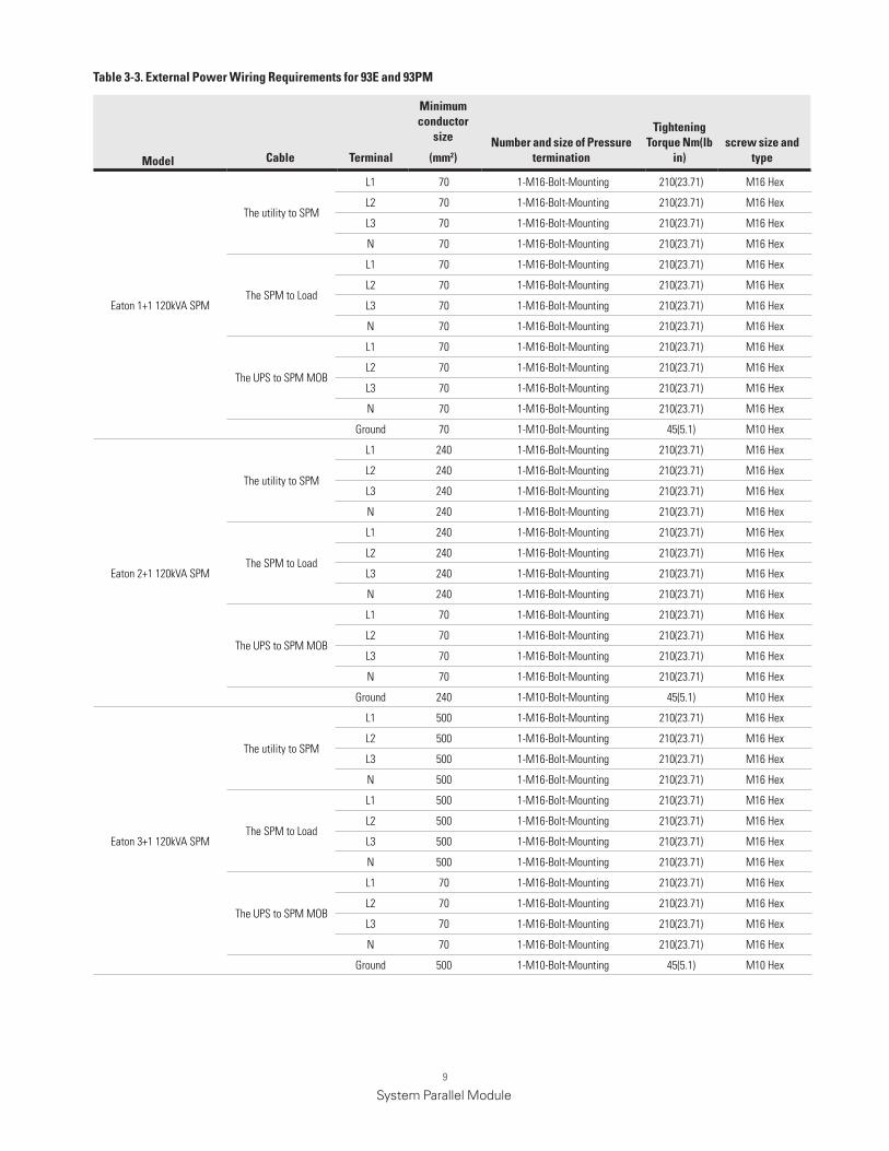
3 .2 .2 SPm Wiring Preparation
• Refer to national and local electrical codes for acceptable external wiring practices.
• Material and labor for external wiring requirements are to be provided by the customer.
• For external wiring, use 90°C copper wire. Wire sizes listed in Table 3-3 are for copper wiring only. If wire is run in an ambient temperature greater than 30°C, higher temperature wire and/or larger size wire may be necessary. Wire sizes are based on using the specified breakers.
• Refer to the appropriate Eaton 93E 80-200kVA and 93PM 50-200 kW UPS Installation and Operation manual listed in corresponding paragraph for UPS cabinet conduit and terminal specifications and locations.
• The term line-up-and-match refers to accessory cabinets that are physically located adjacent to the UPS. The term standalone refers to accessory cabinets that are located separate from the UPS.
For external power wiring requirements, including the minimum size of external wiring, see Table 3-3. Wire sizes listed are for copper wiring only.
Figure 4-5 and Figure 4-6 show the location of the SPM power cable terminals.
Read and understand the following notes while planning and performing the installation:
WARNING
As a result of the connected loads high leakage current is possible. Connection to earth ground is required for safety and proper product operation. Do not check SPM operation by any action that includes removal of the earth (ground) connection with loads attached.
9
System Parallel Module
Eaton 1+1 120kVA SPM
The utility to SPM
L1 70 1-M16-Bolt-Mounting 210(23.71) M16 Hex
L2 70 1-M16-Bolt-Mounting 210(23.71) M16 Hex
L3 70 1-M16-Bolt-Mounting 210(23.71) M16 Hex
N 70 1-M16-Bolt-Mounting 210(23.71) M16 Hex
The SPM to Load
L1 70 1-M16-Bolt-Mounting 210(23.71) M16 Hex
L2 70 1-M16-Bolt-Mounting 210(23.71) M16 Hex
L3 70 1-M16-Bolt-Mounting 210(23.71) M16 Hex
N 70 1-M16-Bolt-Mounting 210(23.71) M16 Hex
The UPS to SPM MOB
L1 70 1-M16-Bolt-Mounting 210(23.71) M16 Hex
L2 70 1-M16-Bolt-Mounting 210(23.71) M16 Hex
L3 70 1-M16-Bolt-Mounting 210(23.71) M16 Hex
N 70 1-M16-Bolt-Mounting 210(23.71) M16 Hex
Ground 70 1-M10-Bolt-Mounting 45(5.1) M10 Hex
Eaton 2+1 120kVA SPM
The utility to SPM
L1 240 1-M16-Bolt-Mounting 210(23.71) M16 Hex
L2 240 1-M16-Bolt-Mounting 210(23.71) M16 Hex
L3 240 1-M16-Bolt-Mounting 210(23.71) M16 Hex
N 240 1-M16-Bolt-Mounting 210(23.71) M16 Hex
The SPM to Load
L1 240 1-M16-Bolt-Mounting 210(23.71) M16 Hex
L2 240 1-M16-Bolt-Mounting 210(23.71) M16 Hex
L3 240 1-M16-Bolt-Mounting 210(23.71) M16 Hex
N 240 1-M16-Bolt-Mounting 210(23.71) M16 Hex
The UPS to SPM MOB
L1 70 1-M16-Bolt-Mounting 210(23.71) M16 Hex
L2 70 1-M16-Bolt-Mounting 210(23.71) M16 Hex
L3 70 1-M16-Bolt-Mounting 210(23.71) M16 Hex
N 70 1-M16-Bolt-Mounting 210(23.71) M16 Hex
Ground 240 1-M10-Bolt-Mounting 45(5.1) M10 Hex
Eaton 3+1 120kVA SPM
The utility to SPM
L1 500 1-M16-Bolt-Mounting 210(23.71) M16 Hex
L2 500 1-M16-Bolt-Mounting 210(23.71) M16 Hex
L3 500 1-M16-Bolt-Mounting 210(23.71) M16 Hex
N 500 1-M16-Bolt-Mounting 210(23.71) M16 Hex
The SPM to Load
L1 500 1-M16-Bolt-Mounting 210(23.71) M16 Hex
L2 500 1-M16-Bolt-Mounting 210(23.71) M16 Hex
L3 500 1-M16-Bolt-Mounting 210(23.71) M16 Hex
N 500 1-M16-Bolt-Mounting 210(23.71) M16 Hex
The UPS to SPM MOB
L1 70 1-M16-Bolt-Mounting 210(23.71) M16 Hex
L2 70 1-M16-Bolt-Mounting 210(23.71) M16 Hex
L3 70 1-M16-Bolt-Mounting 210(23.71) M16 Hex
N 70 1-M16-Bolt-Mounting 210(23.71) M16 Hex
Ground 500 1-M10-Bolt-Mounting 45(5.1) M10 Hex
model Cable Terminal
minimum conductor
size
(mm2)number and size of Pressure
termination
Tightening Torque nm(lb
in)screw size and
type
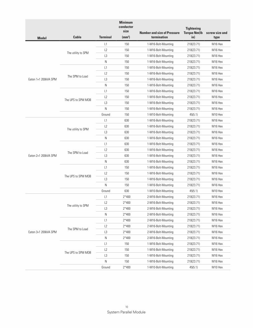
Table 3-3 . External Power Wiring requirements for 93E and 93Pm
10
System Parallel Module
Eaton 1+1 200kVA SPM
The utility to SPM
L1 150 1-M16-Bolt-Mounting 210(23.71) M16 Hex
L2 150 1-M16-Bolt-Mounting 210(23.71) M16 Hex
L3 150 1-M16-Bolt-Mounting 210(23.71) M16 Hex
N 150 1-M16-Bolt-Mounting 210(23.71) M16 Hex
The SPM to Load
L1 150 1-M16-Bolt-Mounting 210(23.71) M16 Hex
L2 150 1-M16-Bolt-Mounting 210(23.71) M16 Hex
L3 150 1-M16-Bolt-Mounting 210(23.71) M16 Hex
N 150 1-M16-Bolt-Mounting 210(23.71) M16 Hex
The UPS to SPM MOB
L1 150 1-M16-Bolt-Mounting 210(23.71) M16 Hex
L2 150 1-M16-Bolt-Mounting 210(23.71) M16 Hex
L3 150 1-M16-Bolt-Mounting 210(23.71) M16 Hex
N 150 1-M16-Bolt-Mounting 210(23.71) M16 Hex
Ground 150 1-M10-Bolt-Mounting 45(5.1) M10 Hex
Eaton 2+1 200kVA SPM
The utility to SPM
L1 630 1-M16-Bolt-Mounting 210(23.71) M16 Hex
L2 630 1-M16-Bolt-Mounting 210(23.71) M16 Hex
L3 630 1-M16-Bolt-Mounting 210(23.71) M16 Hex
N 630 1-M16-Bolt-Mounting 210(23.71) M16 Hex
The SPM to Load
L1 630 1-M16-Bolt-Mounting 210(23.71) M16 Hex
L2 630 1-M16-Bolt-Mounting 210(23.71) M16 Hex
L3 630 1-M16-Bolt-Mounting 210(23.71) M16 Hex
N 630 1-M16-Bolt-Mounting 210(23.71) M16 Hex
The UPS to SPM MOB
L1 150 1-M16-Bolt-Mounting 210(23.71) M16 Hex
L2 150 1-M16-Bolt-Mounting 210(23.71) M16 Hex
L3 150 1-M16-Bolt-Mounting 210(23.71) M16 Hex
N 150 1-M16-Bolt-Mounting 210(23.71) M16 Hex
Ground 630 1-M10-Bolt-Mounting 45(5.1) M10 Hex
Eaton 3+1 200kVA SPM
The utility to SPM
L1 2*400 2-M16-Bolt-Mounting 210(23.71) M16 Hex
L2 2*400 2-M16-Bolt-Mounting 210(23.71) M16 Hex
L3 2*400 2-M16-Bolt-Mounting 210(23.71) M16 Hex
N 2*400 2-M16-Bolt-Mounting 210(23.71) M16 Hex
The SPM to Load
L1 2*400 2-M16-Bolt-Mounting 210(23.71) M16 Hex
L2 2*400 2-M16-Bolt-Mounting 210(23.71) M16 Hex
L3 2*400 2-M16-Bolt-Mounting 210(23.71) M16 Hex
N 2*400 2-M16-Bolt-Mounting 210(23.71) M16 Hex
The UPS to SPM MOB
L1 150 1-M16-Bolt-Mounting 210(23.71) M16 Hex
L2 150 1-M16-Bolt-Mounting 210(23.71) M16 Hex
L3 150 1-M16-Bolt-Mounting 210(23.71) M16 Hex
N 150 1-M16-Bolt-Mounting 210(23.71) M16 Hex
Ground 2*400 1-M10-Bolt-Mounting 45(5.1) M10 Hex
model Cable Terminal
minimum conductor
size
(mm2)number and size of Pressure
termination
Tightening Torque nm(lb
in)screw size and
type
11
System Parallel Module
For the following steps, use pincer type pliers or a large flat blade screw driver to straighten the securing tabs.
NOTE
For the following step, verify that the forklift or pallet jack is rated to handle the weight of the cabinets (see Table 3-1 for cabinet weight).
NOTE
1. Carefully inspect the outer packaging for evidence of damage during transit.
CAUTION
Do not install a damaged cabinet. Report any damages to the carrier and contact an Eaton service representative immediately.
2. Use a forklift or pallet jack to move the packaged cabinet to the installation site, or as close as possible, before unpacking. If possible, move the cabinets using the pallet. Insert the forklift or pallet jack forks between the supports on the bottom of the pallet .
3. Remove the protective wood/carton container from the cabinet:
CAUTION
• DonottilttheSPMcabinetsmorethan10°fromverticalorthecabinetsmaytipover.
4. Remove the inner protective packaging. Retain the parts kit box, ramp brackets, and ramp extension packed at the top of the cabinet.
a. Straighten the tabs securing the top panel of the wooden container to the side panels of the container.
b. Remove the top panel and retain for later use as a ramp in unloading the cabinet from the pallet.
c. Straighten the tabs securing the side panels of the container to the front and back panels of the container.
d. Remove the side panels.
e. Straighten the tabs securing the front and back panels of the container to the bottom of the container.
f. Remove the front and back panels.
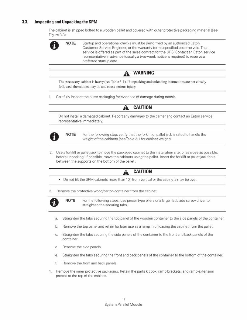
3 .3 . Inspecting and Unpacking the SPm
The cabinet is shipped bolted to a wooden pallet and covered with outer protective packaging material (see Figure 3-3).
WARNING
The Accessory cabinet is heavy (see Table 3-1). If unpacking and unloading instructions are not closely followed, the cabinet may tip and cause serious injury.
Startup and operational checks must be performed by an authorized Eaton Customer Service Engineer, or the warranty terms specified become void. This service is offered as part of the sales contract for the UPS. Contact an Eaton service representative in advance (usually a two-week notice is required) to reserve a preferred startup date.
NOTE
12
System Parallel Module
While waiting for installation, protect the unpacked cabinet from moisture, dust, and other harmful contaminants. Failure to store and protect the SPM properly may void your warranty.
NOTE
5. Recycle the remainder of the outer shipping container and the inner protective packaging in a responsible manner.
6. Inspect the contents for any evidence of physical damage, and compare each item with the Bill of Lading. If damage has occurred or shortages are evident, contact an Eaton service representative immediately to determine the extent of the damage and its impact on further installation.
figure 3-3 . SPm Cabinet as Shipped on Pallet (wood container removed)
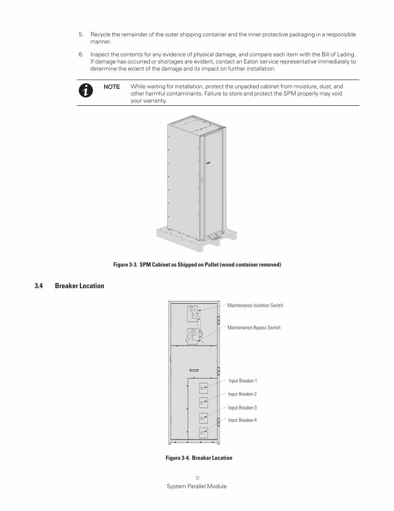
3 .4 Breaker location
figure 3-4 . Breaker location
Maintenance Isolation Switch
Maintenance Bypass Switch
Input Breaker-1
Input Breaker-2
Input Breaker-3
Input Breaker-4
13
System Parallel Module
Chapter 4 Installation
4 .1 Preliminary Installation Information
Refer to the following while installing the SPM:
• To review the SPM manual, Chapter 3 of this manual for cabinet dimensions, equipment weight, wiring and installation notes.
• Do not tilt the cabinets more than ±10° during installation.
• Suitable for mounting on concrete or other non-combustible surfaces only.
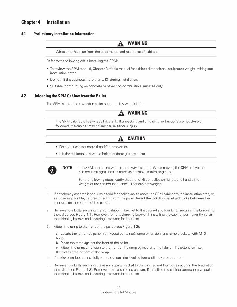
1. If not already accomplished, use a forklift or pallet jack to move the SPM cabinet to the installation area, or as close as possible, before unloading from the pallet. Insert the forklift or pallet jack forks between the supports on the bottom of the pallet .
2. Remove four bolts securing the front shipping bracket to the cabinet and four bolts securing the bracket to the pallet (see Figure 4-1). Remove the front shipping bracket. If installing the cabinet permanently, retain the shipping bracket and securing hardware for later use.
3. Attach the ramp to the front of the pallet (see Figure 4-2):
a. Locate the ramp (top panel from wood container), ramp extension, and ramp brackets with M10 bolts.b. Place the ramp against the front of the pallet.c. Attach the ramp extension to the front of the ramp by inserting the tabs on the extension into the slots at the bottom of the ramp.
4. If the leveling feet are not fully retracted, turn the leveling feet until they are retracted.
5. Remove four bolts securing the rear shipping bracket to the cabinet and four bolts securing the bracket to the pallet (see Figure 4-3). Remove the rear shipping bracket. If installing the cabinet permanently, retain the shipping bracket and securing hardware for later use.
WARNING
Wires enter/out can from the bottom, top and rear holes of cabinet.
4 .2 Unloading the SPm Cabinet from the Pallet
The SPM is bolted to a wooden pallet supported by wood skids.
WARNING
The SPM cabinet is heavy (see Table 3-1). If unpacking and unloading instructions are not closely followed, the cabinet may tip and cause serious injury.
CAUTION
• Do not tilt cabinet more than 10° from vertical.
• Lift the cabinets only with a forklift or damage may occur.
The SPM uses inline wheels, not swivel casters. When moving the SPM, move the cabinet in straight lines as much as possible, minimizing turns.
For the following steps, verify that the forklift or pallet jack is rated to handle the weight of the cabinet (see Table 3-1 for cabinet weight).
NOTE
14
System Parallel Module
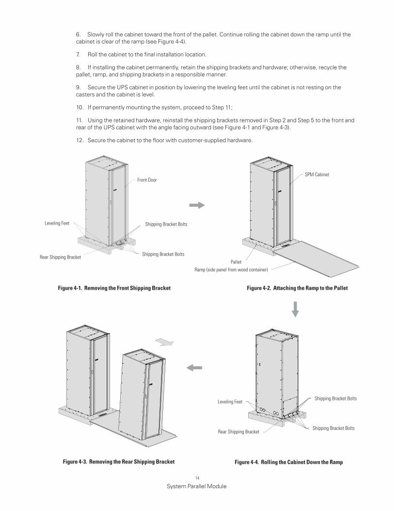
6. Slowly roll the cabinet toward the front of the pallet. Continue rolling the cabinet down the ramp until the cabinet is clear of the ramp (see Figure 4-4).
7. Roll the cabinet to the final installation location.
8. If installing the cabinet permanently, retain the shipping brackets and hardware; otherwise, recycle the pallet, ramp, and shipping brackets in a responsible manner.
9. Secure the UPS cabinet in position by lowering the leveling feet until the cabinet is not resting on the casters and the cabinet is level.
10. If permanently mounting the system, proceed to Step 11;
11. Using the retained hardware, reinstall the shipping brackets removed in Step 2 and Step 5 to the front and rear of the UPS cabinet with the angle facing outward (see Figure 4-1 and Figure 4-3).
12. Secure the cabinet to the floor with customer-supplied hardware.
figure 4-1 . removing the front Shipping Bracket figure 4-2 . Attaching the ramp to the Pallet
figure 4-3 . removing the rear Shipping Bracket figure 4-4 . rolling the Cabinet down the ramp
Rear Shipping Bracket Shipping Bracket Bolts
Shipping Bracket Bolts
Front Door
Leveling Feet
Ramp (side panel from wood container)
SPM Cabinet
Pallet
Rear Shipping Bracket Shipping Bracket Bolts
Shipping Bracket BoltsLeveling Feet
15
System Parallel Module
4 .3 External Power Cables Connecting
WARNING
WARNING
Verify phases of connections. Risk of personal injury and damage to equipment from arc flash if
connections are reversed.
• TURN OFF UPS AND DISCONNECT UPS FROM POWER SUPPLY BEFORE SPM INSTALLATION.
• HIGH TOUCH CURRENT. EARTH CONNECTION MUST BEFORE CONNECTING SUPPLY. As a
result of the connected loads high leakage current is possible. Connection of the earth (ground) is
required for proper product operation. Do not check UPS operation by removal of the Earth (ground)
connection.
To install wires:
1. If installing wiring using conduit, please punch or drill hole on the bottom and top cover plates.
2. Install conduit between the UPS cabinet and SPM if needed.
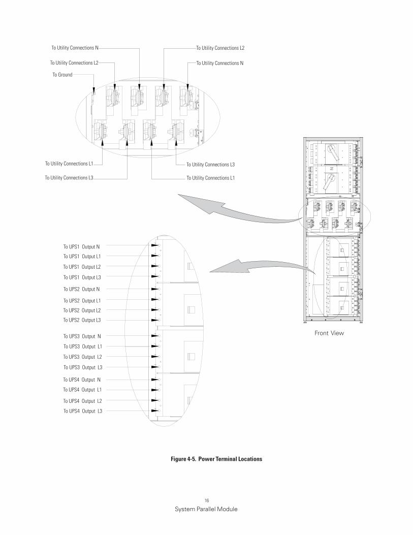
3. Ground the SPM according to local and/or national electrical wiring codes by routing and connecting the ground wire to the input ground lug. See Figure 4-5 for SPM terminal locations.
4. Route and connect the power cables(L1,L2,L3,N) from the utility source to the SPM phase and terminal blocks. See Figure 4-5 for wiring access information and terminal locations. See paragraph 3.2.2,Table 3-3 for wiring and termination requirements.
The utility source must be the same as the UPS bypass input.
5. Route and Connect the power cables(L1,L2,L3,N ) from the Load to the SPM phase and terminal blocks. See Figure 4-5 for wiring access information and terminal locations. See paragraph 3.2.2,Table 3-3 for wiring and termination requirements.
6. 5 Route and Connect the power cables(L1,L2,L3,N ) from the UPS to the SPM phase terminal blocks. See Figure 4-5 for wiring access information and terminal locations. See paragraph 3.2.2,Table 3-3 for wiring and termination requirements.
Wires enter/out from the bottom conduit landing plate or knock-out holes on 2 side plates.
NOTE
4 .4 External Signaling Cables Connecting
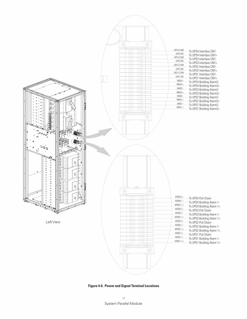
To install the signal wires:
Refer figure 4-6 to install the signal wires. The wire code is minimum 22AWG.
1. Please refer to the appropriate Eaton 93E80-200kVA and 93PM 50-200kW UPS installation and operation manual listed in corresponding paragraph for pull chain and building alarm connections.
2. To located the appropriate terminals and review the wiring and terminal requirement see Figure 4-6.
To avoid the interface between the power cables and signal wires, please route the cables separate.
NOTE
16
System Parallel Module
figure 4-5 . Power Terminal locations
Front View
To Utility Connections N
To Utility Connections L2
To Ground
To Utility Connections L1
To Utility Connections L3
To Utility Connections L2
To Utility Connections N
To Utility Connections L3
To Utility Connections L1
To UPS1 Output N
To UPS2 Output N
To UPS3 Output N
To UPS4 Output N
To UPS1 Output L1
To UPS2 Output L1
To UPS3 Output L1
To UPS4 Output L1
To UPS1 Output L2
To UPS2 Output L2
To UPS3 Output L2
To UPS4 Output L2
To UPS2 Output L3
To UPS1 Output L3
To UPS3 Output L3
To UPS4 Output L3
17
System Parallel Module
figure 4-6 . Power and Signal Terminal locations
Left View
UPS4 COMUPS4 NC
UPS3 COMUPS3 NC
UPS2 COM
UPS2 NCUPS1 COM
UPS1 NC
MBS4 -MBS4 +
MBS3 -
MBS3 +MBS2 -MBS2 +
MBS1 -MBS1 +
MOB4-2 -
MOB4-1 -
MOB4-1 +
MOB3-2 -
MOB3-1 -
MOB3-1 +
MOB2-2 -
MOB2-1 -
MOB2-1 +
MOB1-2 -
MOB1-1 -
MOB1-1 +
To UPS4 Interface CN7-To UPS4 Interface CN7+To UPS3 Interface CN7-To UPS3 Interface CN7+To UPS2 Interface CN7-To UPS2 Interface CN7+To UPS1 Interface CN7-To UPS1 Interface CN7+To UPS4 Building Alarm2-To UPS4 Building Alarm2+To UPS3 Building Alarm2-To UPS3 Building Alarm2+To UPS2 Building Alarm2-To UPS2 Building Alarm2+To UPS1 Building Alarm2-To UPS1 Building Alarm2+
To UPS4 Pull Chain-To UPS4 Building Alarm 1-To UPS4 Building Alarm 1+To UPS3 Pull Chain-To UPS3 Building Alarm 1-To UPS3 Building Alarm 1+To UPS2 Pull Chain-To UPS2 Building Alarm 1-To UPS2 Building Alarm 1+To UPS1 Pull Chain-To UPS1 Building Alarm 1-To UPS1 Building Alarm 1+
18
System Parallel Module
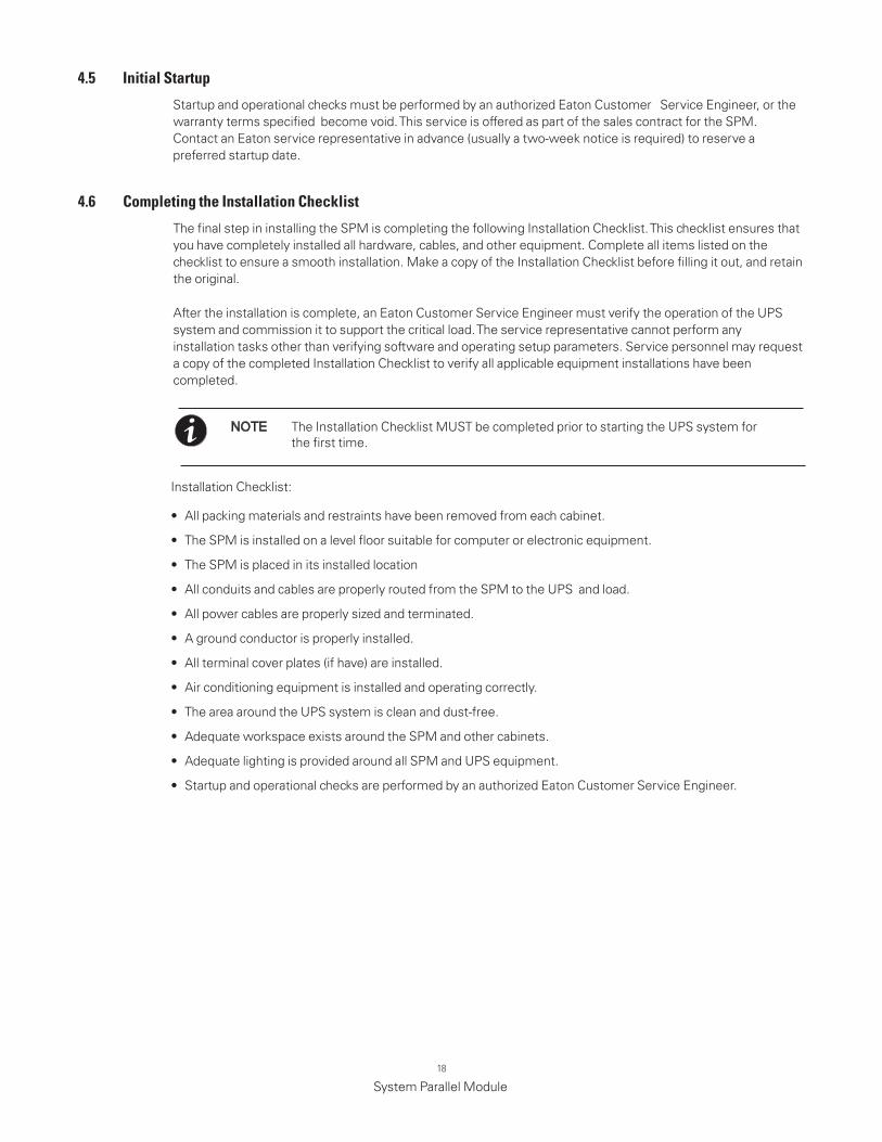
4 .5 Initial Startup
4 .6 Completing the Installation Checklist
The Installation Checklist MUST be completed prior to starting the UPS system for the first time.
NOTE
Startup and operational checks must be performed by an authorized Eaton Customer Service Engineer, or the warranty terms specified become void. This service is offered as part of the sales contract for the SPM. Contact an Eaton service representative in advance (usually a two-week notice is required) to reserve a preferred startup date.
The final step in installing the SPM is completing the following Installation Checklist. This checklist ensures that you have completely installed all hardware, cables, and other equipment. Complete all items listed on the checklist to ensure a smooth installation. Make a copy of the Installation Checklist before filling it out, and retain the original.
After the installation is complete, an Eaton Customer Service Engineer must verify the operation of the UPS system and commission it to support the critical load. The service representative cannot perform any installation tasks other than verifying software and operating setup parameters. Service personnel may request a copy of the completed Installation Checklist to verify all applicable equipment installations have been completed.
Installation Checklist:
• All packing materials and restraints have been removed from each cabinet.
• The SPM is installed on a level floor suitable for computer or electronic equipment.
• The SPM is placed in its installed location
• All conduits and cables are properly routed from the SPM to the UPS and load.
• All power cables are properly sized and terminated.
• A ground conductor is properly installed.
• All terminal cover plates (if have) are installed.
• Air conditioning equipment is installed and operating correctly.
• The area around the UPS system is clean and dust-free.
• Adequate workspace exists around the SPM and other cabinets.
• Adequate lighting is provided around all SPM and UPS equipment.
• Startup and operational checks are performed by an authorized Eaton Customer Service Engineer.

19
System Parallel Module
notes
20
System Parallel Module
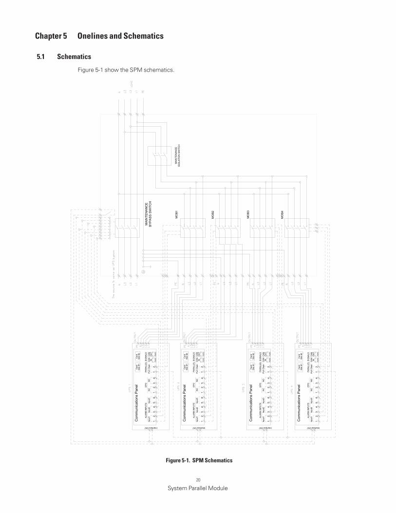
Chapter 5 onelines and Schematics
5 .1 Schematics
Figure 5-1 show the SPM schematics.
figure 5-1 . SPm Schematics
MO
B1
MO
B2
MO
B3
MO
B4
MA
INTE
NAN
CE
ISO
LATI
ON
SW
ITC
H
MA
INTE
NAN
CE
BY
PA
SS
SW
ITC
HA
LAR
M IN
PUTS
Inpu
t1
Com
mun
icat
ions
Pan
el
12
Inpu
t2
34
Inpu
t3
56
EPO
NC
12
NO
34
Pul
l Cha
in
12
PAR
ALLE
L SI
GN
ALS
RJ4
5R
J45
CAN IN
CAN
OU
T
Car
dS
lot #
1C
ard
Slo
t #2
ALA
RM
INPU
TSIn
put1
Com
mun
icat
ions
Pan
el
12
Inpu
t2
34
Inpu
t3
56
EPO
NC
12
NO
34
Pul
l Cha
in
12
PAR
ALLE
L SI
GN
ALS
RJ4
5R
J45
CAN IN
CAN
OU
T
Car
dS
lot #
1C
ard
Slo
t #2
ALA
RM
INPU
TSIn
put1
Com
mun
icat
ions
Pan
el
12
Inpu
t2
34
Inpu
t3
56
EPO
NC
12
NO
34
Pul
l Cha
in
12
PAR
ALLE
L SI
GN
ALS
RJ4
5R
J45
CAN IN
CAN
OU
T
Car
dS
lot #
1C
ard
Slo
t #2
ALA
RM
INPU
TSIn
put1
Com
mun
icat
ions
Pan
el
12
Inpu
t2
34
Inpu
t3
56
EPO
NC
12
NO
34
Pul
l Cha
in
12
PAR
ALLE
L SI
GN
ALS
RJ4
5R
J45
CAN IN
CAN
OU
T
Car
dS
lot #
1C
ard
Slo
t #2
Interface CN7 Interface CN7 Interface CN7 Interface CN7
21
System Parallel Module
Chapter 6 maintenance
The components inside the SPM are secured to a sturdy metal frame. All repairable parts and assemblies are located for easy removal, with very little disassembly. This design allows authorized service personnel to perform routine maintenance and servicing quickly.
You must schedule periodic performance checks of the UPS system to keep it running properly. Regular routine checks of operation and system parameters enable your system to function efficiently for many trouble-free years.
6 .1 Important Safety Instructions
Remember that your UPS system is designed to supply power EVEN WHEN DISCONNECTED FROM THE UTILITY POWER.
WARNING
• No user serviceable components.
• Servicing and maintenance should be performed by qualified service personnel only.
• LETHAL VOLTAGE PRESENT. This unit should not be operated with the cabinet doors open or protective panels removed. Do not make any assumptions about the electrical state of any cabinet in the UPS system.
The UPS system requires very little preventive maintenance. However, the system should be inspected periodically to verify that the units are operating normally. Record maintenance results and any corrective actions in a suitable log.
6 .2 .1 dAIly maintenance
6 .2 .2 PErIodIC maintenance
6 .2 .3 AnnUAl maintenance
6 .2 .4 BATTEry maintenance
Perform the following steps daily:
1. Check the area surrounding the UPS system. Ensure the area is not cluttered, allowing free access to the unit.
2. Ensure the operating environment is within the parameters specified in paragraph 3.2.1 and Chapter 7, “Product Specifications.”
Periodic inspections of the SPM should be made to determine if components, wiring, and connections exhibit evidence of overheating. Particular attention should be given to the compression lug connections. Maintenance procedures should specify that the compression lug connections be re-torqued to values listed in this manual.
Annual preventive maintenance should be performed only by authorized service personnel familiar with maintenance and servicing of the UPS system. Contact an Eaton service representative for more information about service offerings.
Contact an Eaton service representative for battery maintenance. Battery replacement and maintenance should be performed only by authorized service personnel.
6 .2 Performing Preventive maintenance
6 .3 maintenance Training
A basic training course, available from Eaton Corporation, gives you a competent working knowledge of the UPS system operation and teaches you how to perform first level corrective maintenance. For more information about training and other services, contact the Help Desk .see paragraph 1.7.
22
System Parallel Module
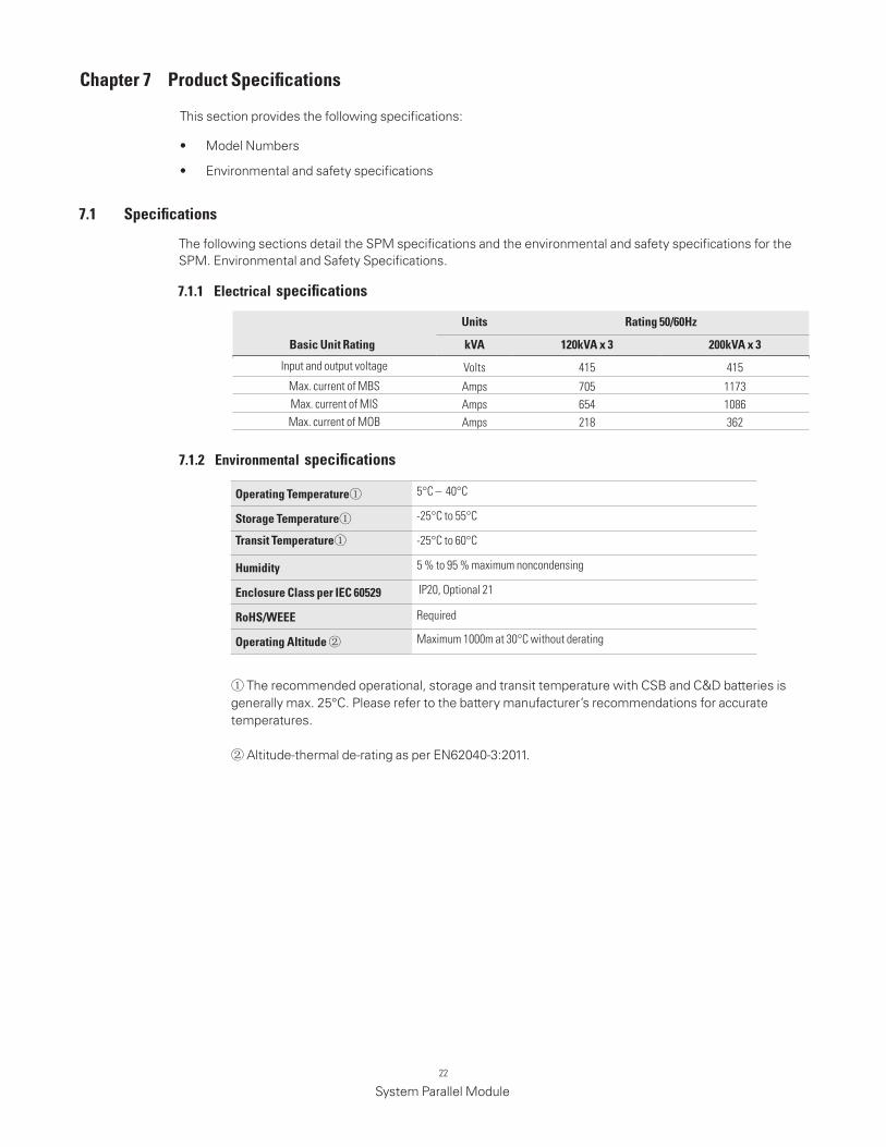
Chapter 7 Product Specifications
The following sections detail the SPM specifications and the environmental and safety specifications for the SPM. Environmental and Safety Specifications.
This section provides the following specifications:
• Model Numbers
• Environmental and safety specifications
7 .1 Specifications
Basic Unit rating
Units rating 50/60hz
kVA 120kVA x 3 200kVA x 3
Input and output voltage Volts 415 415
Max. current of MBS Amps 705 1173Max. current of MIS Amps 654 1086Max. current of MOB Amps 218 362
operating Temperature① 5°C – 40°C
Storage Temperature① -25°C to 55°C
Transit Temperature① -25°C to 60°C
humidity 5 % to 95 % maximum noncondensing
Enclosure Class per IEC 60529 IP20, Optional 21
rohS/WEEE Required
operating Altitude ② Maximum 1000m at 30°C without derating
① The recommended operational, storage and transit temperature with CSB and C&D batteries is generally max. 25°C. Please refer to the battery manufacturer’s recommendations for accurate temperatures.
② Altitude-thermal de-rating as per EN62040-3:2011.
7 .1 .2 Environmental specifications
7 .1 .1 Electrical specifications


614-01728-00