Embed Size (px)
Citation preview

1
18-545 Fall 2012
Teal Rime Tray Racer:
Final Report
12/18/12
Ross Daly Paul Kennedy Ryan Macdonald

2
Contents
1. Overview ................................................................................................................................................... 3
2. Hardware ................................................................................................................................................... 4
2.1 Architectural Overview ....................................................................................................................... 4
2.2 XMODEM .......................................................................................................................................... 5
2.3 Scene Loader ....................................................................................................................................... 5
2.4 PS/2 ..................................................................................................................................................... 6
2.5 Camera Control ................................................................................................................................... 6
2.6 Ray Pipe .............................................................................................................................................. 7
2.6.1 Overview of Ray Tracing Algorithm ........................................................................................... 9
2.6.2 Primary Ray Generator .............................................................................................................. 10
2.6.3 Scene Intersection Unit .............................................................................................................. 11
2.6.4 Arbiters ...................................................................................................................................... 11
2.6.5 Caches ........................................................................................................................................ 11
2.6.6 Raystore ..................................................................................................................................... 11
2.6.7 Traversal Unit ............................................................................................................................ 12
2.6.8 Intersection Unit ......................................................................................................................... 12
2.6.9 Shortstack ................................................................................................................................... 13
2.6.10 List Unit ................................................................................................................................... 14
2.6.11 Shader ...................................................................................................................................... 14
2.7 Pixel Buffer ....................................................................................................................................... 17
2.8 Frame Buffer Handler ....................................................................................................................... 17
2.9 Important Demos .............................................................................................................................. 18
2.9.1 sint demo .................................................................................................................................... 18
2.9.2 t32 .............................................................................................................................................. 18
3. Software .................................................................................................................................................. 19
3.1 Ray Tracer for 15-462 ....................................................................................................................... 19
3.2 K-d tree construction ......................................................................................................................... 19
3.3 Scene file generation ......................................................................................................................... 20
3.3.1 K-d tree ...................................................................................................................................... 20
3.3.2 Node Triangle Lists ........................................................................................................................ 21
3.3.2 Triangle Transformation Matrices ................................................................................................. 21

3
3.3.3 Triangle Colors and Normals ......................................................................................................... 21
3.3.4 Scene Bounding Box .................................................................................................................. 21
4. Design Decisions .................................................................................................................................... 22
5. Testing Methodology .............................................................................................................................. 24
6. Results ..................................................................................................................................................... 25
7. Individual Comments .............................................................................................................................. 26
8. Appendix ................................................................................................................................................. 31
7.1 Serial ................................................................................................................................................. 31
7.2 XMODEM ........................................................................................................................................ 31
7.3 VGA .................................................................................................................................................. 32
7.4 PS/2 ................................................................................................................................................... 32
7.5 SDRAM Notes .................................................................................................................................. 32
7.6 Bibligraphy ....................................................................................................................................... 33
1. Overview
This section provides an overview of the project including brief descriptions of both the hardware and
software sides of the project as well as a brief description of the content of each major section of this
document.
The goal of Team Rime Tray Racer is to be a real-time ray tracer. In order to accomplish real-time
performance, we have made many design decisions which each come with their own trade-offs in terms
of realism and features. Some of the most important decisions include those which decide what
computations are to be done in software on a computer instead of in hardware on the FPGA itself.
We have decided to perform as much computation in software as possible. This includes: construction of
a k-d tree; flattening meshes of triangles into a single list of triangles; transforming all of the triangles into
a unit triangle coordinate space.
Once a scene file has been generated in software, it is transferred to the FPGA over a serial port
connection at which point the hardware can start perform the raytracing algorithm on the scene.
Section 2 provides a detailed description of the hardware side of this project both from a high level
perspective as well as each submodule. Section 3 describes the software side of this project including the
construction of k-d trees and scene file generation. Section 4 describes many of the major design
decisions for this project while section 5 describes our testing methodology throughout the semester.
Section 6 contains our individual comments on the project and the report ends with an appendix in section
7 with details on many of the protocols we use including VGA, PS/2 and XMODEM.

4
2. Hardware
This section provides detailed descriptions of the aspects of this project which were implemented in
hardware. It begins with an overview of the architecture and then discusses each major block as well as
each of the ray tracing pipeline modules in detail.
2.1 Architectural Overview
This section provides a diagram1 of the architecture and an overview of the way in which the major
blocks work together to render a scene.
1 The memory request arbiter was ultimately removed from this project which is why it is in gray.

5
Before scenes can be rendered using the ray tracer pipeline, scene data must first be loaded into the
memory. Scene data includes information such as the position and orientation of objects within the scene
as well as their color, specularity, textures, and so on. It also includes the initial position and direction of
the camera. All of this data is compiled into a binary file by software running on a computer. The process
of compiling this file is described in detail in section 3.
The data is transferred onto the FPGA via the RS-232 UART serial port using the XMODEM protocol.
As this data is transferred, it is stored into SDRAM memory by the scene loader module. Some
information, such as lighting data and camera position, is stored in special registers within the
architecture.
Once transfer and storage of the scene data is complete, the ray tracing pipeline can begin the process of
rendering the scene. Primary rays, one per pixel, are generated and enter the pipeline. As pixel data retires
from the ray tracing pipeline, it is stored into the frame buffer located in SRAM. Once the entire screen
has been rendered, the frame buffer handler switches its designation of "complete" and "incomplete"
frame buffers. The VGA controller works together with the frame buffer handler to output 24-bit colors to
the VGA DAC chip.
The process of rendering the scene repeats if, at any time, something which would affect the appearance
of the screen changes. This includes any change in the camera's position and orientation, as well as any
changes in the lighting2. The user may control these aspects of the scene using the keyboard, mouse and
the on-board buttons and switches.
2.2 XMODEM
The XMODEM module is responsible for receiving the data from the RS-232 Serial port and providing it
to the rest of the design (specifically, via the scene loader). This module expects data to be transferred
using the XMODEM protocol at a baud rate of 115,200. It also expects 1 start bit, 8 data bits, no parity
bit, and no flow control.
The XMODEM module has three levels of abstraction: the bit-level FSMD, the block-level FSMD, and
the protocol FSMD. More details about the XMODEM protocol can be found in the appendix.
2.3 Scene Loader
The purpose of the scene_loader module is to take data coming from the XMODEM module and
store it into memory, where ever that may be. In most cases that will be the main memory of the system,
but in some cases it may be into special registers e.g. those storing the bounding box of the scene.3
The scene loader originally was intended to stored most of the data into the DRAM memory by way of
the memory request arbiter. However, because DRAM was ultimately not used in this project, the scene
2 We did not finish lighting for this project so the only thing which can cause the scene to be rerendered is a change
in the camera position. 3 We originally intended store the positions of lights, initial camera position, and background color in registers. We
did not get around to implementing these, however.
6
loader stores its data directly into the simplified "caches" (which are actually just block RAM modules
storing all of the scene data).
As is detailed in the section on scene file generation, the scene file is broken into sections based on the
kind of data being transmitted. The sizes of these sections are specified by the first 4 bytes of the section.
The scene loader thus knows when to expect these bytes and keeps a count of how many bytes have been
received for the current section. Once all of the bytes for a given section have been received, the scene
loader begins storing data for the next section.
The scene loader receives a byte at a time from the XMODEM module as well as several status signals
such as xmodem_saw_valid_msg_byte and xmodem_done. Because the XMODEM protocol
allows for blocks of data to be resent (for example, in the case of an invalid checksum or block number),
the fact that the scene loader receives only one byte at a time presents a difficulty. A section of data can
begin and end at any point within a 128 byte block of data from XMODEM, which means that if a block
is determined to be invalid and must be resent, the scene loader must not only restore this data into
memory, it must also return the byte count and section register back to whatever state they were in at the
beginning of the block.
This is ability to roll back the state of the scene loader upon an invalid block in implemented using a
checkpoint mechanism. Whenever the scene loader finishes receiving a new, valid block of data, it saves
the entire state of the scene loader in a checkpoint register. If the next block of data proves to be an
invalid block (or a repeated valid block), the scene loader restores its state back to the previous
checkpoint.
The entire state of the module is held in a packed struct called sl_state defined in scene_loader.sv. By
using a struct, it is very easy to ensure that any stateful elements which need to be saved or restored are
handled appropriately.
The scene loader expects a file format that is completely dependent upon the format created by the
software program. Currently the sections are in the order as follows: K-d tree, leaf node triangle lists, unit
triangle transformation matrices, ambient triangle colors and normal vectors, scene bounding box.
2.4 PS/2
The PS/2 modules are responsible for interpreting the signals from the keyboard and alerting the rest of
the design that a key has been pressed or released. This data is sent to the camera control unit which
updates the camera position accordingly. Details about the PS/2 protocol can be found in the appendix.
2.5 Camera Control
The camera controller is responsible for changing the position and orientation of the camera depending on
input from the keyboard. The camera has a translate feature and a rotate feature. This camera rotation
scheme was designed to work without trigonometric calculations, which can be expensive in latency and
number of logic elements required.
7
The camera can be moved in real time by using the PS/2 devices (i.e. keyboard and mouse). Registers in
the camera control unit store the current position and orientation of the camera. This information is
retrieved by the primary ray generator of the ray tracing pipeline in order to generate primary rays which
originate from the camera position.
When a user presses a translation key (‘Q’, ‘W’, ‘E’, ‘A’, ‘S’, ‘D’), the camera controller asserts a signal
to the raypipe indicating that a frame is to be rendered and a counter is started. This counter is fed into a
floating point pipeline which calculates the next position of the camera when the initial frame is done
rendering. When this initial frame is done rendering, the newly calculated camera position is used to
render a new frame. This system ensures that the translation of the camera is proportional to the duration
the key is held.
When the translation key is released, the counter is cleared and a new frame is not rendered when the
current frame is done rendering. There are four different camera translation speeds. The user can change
between these by pressed the keys ‘7’, ‘8’, ‘9’, and ‘0’, increasing in speed. This is implemented by using
a scaling factor in the camera control pipeline. When the user chooses a translation speed, this scaling
factor is simply changed to the appropriate value. At the default speed, the user moves 1 unit in the global
coordinate space per second the key is pressed.
When the user presses a rotate key (‘U’, ‘I’, ‘O’, ‘J’, ‘K’, ‘L’), new camera normal vectors are loaded
depending on the key pressed, and the camera controller asserts a signal to the raypipe indicating that a
frame is to be rendered.
The new normal vectors are determined based on a function with the current normal vectors and the
direction of rotation as inputs. To simplify this function, the camera rotates by 45 degrees at a time. One
rotation of 45 degrees occurs on each key press and release, so the magnitude of the rotation does not
change depending on the length of the key press.
2.6 Ray Pipe
The ray pipe is by far the largest module in the design both in terms of number of lines of code and area
consumed on the FPGA. It is tasked with actually performing the ray tracing algorithm and is extremely
complex. This section begins with a diagram of the ray pipe as well as an overview of the algorithm we
implemented. It then discusses each submodule of the ray pipe in turn.
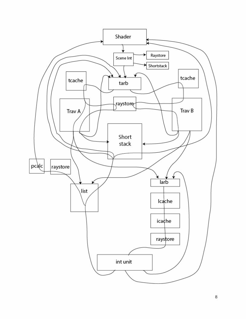
8
9
2.6.1 Overview of Ray Tracing Algorithm
There are a couple of hierarchal goals while performing the ray tracing algorithm. The end goal is to
calculate the colors of all the pixels on the screen given a camera location and camera space. Every single
time the camera data changes (in either direction or location), the ray tracing algorithm is performed again
and the 3D scene is re-rendered. Rays are initially cast from the camera location to the location of each
pixel on the screen which is determined by the camera location, camera direction, camera up vector along
with the size of the screen and the width of a single pixel. This ray casting algorithm forms the heart of
the ray tracing algorithm.
The ray casting algorithm is by far the most complicated hardware algorithm in the system which
involves many pipelined units interfacing with each other (around 20 or so separate interfaces) along with
numerous different date flow paths. A simple summary is that it takes a ray and a scene and returns
whether or not the ray hit any triangle in the scene, which triangle it hit, the point of intersection and the
barycentric coordinates of the intersection point. This is accomplished in a recursive manner described
below.
After the camera controller detects movement in the keyboard (a movement key is pressed on the external
keyboard) a start signal is sent to the ray pipe (I will herby refer to the large conglomeration of units that
make up the ray tracing algorithm as the ray pipe). This start signals triggers the PRG (primary ray
generator) to start creating and sending the initial primary rays into the rest of the ray pipe. These
primary rays are the independent rays sent from the camera position through each of the pixels.
The following is a summary of the life cycle of one of these rays from an algorithms perspective. A ray
will first intersect the scene’s bounding box finding the closest and furthest point of intersection. I use the
word point loosely in this and the following contexts. A point of intersection is functionally equivalent to
a “time” of intersection since rays are represented by a parametric equation. These points of intersection
are saved for later use in the algorithm. A ray will then recursively traverse through the KD tree until it
reaches a leaf node. Nodes that need to be traversed in the future are pushed on to a data structure called
a shortstack during the KD tree traversal. This shortstack is identical to a stack with the additional
functionality of being able to push onto the stack even when the stack is full. A push onto a full stack
results in the previous oldest element of the stack being overwritten.
Once a leaf node is reached, the ray will then intersect all of the triangles contained within the leaf
node. If any of the triangles turn out to be a hit (a proper intersection) and closest hit occurs within the
bounding box of the leaf node, then the algorithm is complete and the results of the hit are returned. If all
the triangles were misses or the closest hit occurred out of the leaf node’s bounding box then the ray pops
a node off of the stack and starts the traversing algorithm again. If there was an infinitely large stack then
a ray would be known to miss all of the triangles in the scene when it needed to pop from an empty
stack. Since we used a shortstack where elements of the stack can be lost, this is now a necessary but not
sufficient condition for determining a complete miss. Whenever a ray tries to pop from an empty stack it
will compare the far intersection of the last leaf node’s bounding box against the intersection of the
scene’s bounding box and if it is greater than or equal, it is determined to be a miss. Otherwise the ray is
still within the bounding box and therefore needs to continue traversing the rest of the KD tree. A restart
then occurs.

10
A restart node is stored along with the stack, which is what the ray uses to restart the recursive
traversal. More information about calculating and storing this restart node is explained in the Traversal
Unit. Once the ray is finally determined to be either a hit or a miss, this information is sent back to the
shader (a unit which calculates pixel colors and dispatches new rays). This shader can do an arbitrarily
complex shading algorithm like shadows and reflections. For example the shader can dispatch a reflected
rays and rays towards lights from points of intersections to accomplish this task.
2.6.2 Primary Ray Generator
The primary ray generator module is responsible for outputting all primary rays to be traced in the system.
It supports a dynamic resolution feature which can be used to change resolution between frames. It
receives the camera origin and normal vectors from the camera controller as well as a start signal which is
asserted when a new frame is to be rendered. When this start signal is asserted, the primary ray generator
will begin to output the appropriate number of rays depending on the resolution.
Given that the full resolution supported is 640x480, the primary ray generator implements six levels of
resolution based on powers of two. This design results in the following resolutions:
(20x15)x1 = 20x15
(20x15)x2 = 40x30
(20x15)x4 = 80x60
(20x15)x8 = 160x120
(20x15)x16 = 320x240
(20x15)x32 = 640x480
In this way, the number of pixels on each row and column is scaled by a factor of two for each level of
granularity and, thus, the total number of pixels rendered between each level of granularity is scaled by a
factor of four. This feature is useful for scenes with large numbers of triangles, a characteristic which
would cause a low frame rate at full resolution. It is helpful because the user is able to decrease resolution
while moving about in the scene to preserve a decent frame rate and then increase it once the desired
position within the scene has been reached.
To increase cache locality, the primary ray generator implements ray packeting. That is, rays which are
going to the same region in the scene are sent out consecutively. It is easiest to illustrate the concept with
a graphic.
In each of these examples, a box represents a 20x15 ray block and the number tells the order in which the
ray block is sent out. The first ray will be sent out at the top-left corner of box 1. Once all 20x15 of the
rays in box 1 have been sent out, the next ray send out will be at the top-left corner of box 2, and so on
with boxes 3, 4, etc.
11
2.6.3 Scene Intersection Unit
The scene intersection unit determines the minimum and maximum points of intersection for a ray and the
scene bounding box.
The unit takes in a ray and six floating point numbers which describe the scene bounding box. The ray
passes through a floating point pipeline which determines tmin and tmax values, values which describe
minimum and maximum points at which the ray intersects with the scene bounding box. The pipeline also
determines whether or not the ray completely misses the scene bounding box.
If the ray does not intersect with the scene bounding box, a miss, then it is not ray traced and sent back to
the shader. If the ray does intersect with the box, it is sent to the traversal arbiter and the shortstack to be
traced in the scene.
2.6.4 Arbiters
The raypipe contains multiple arbiters. These modules are responsible for accepting a certain number of
inputs and distributing them to a certain number of outputs in a fair manner. For example, multiple units
contend for the traversal cache unit and thus an arbiter is required for handling the data from these units.
There is also an arbiter required for the list cache.
2.6.5 Caches
The original intent of the caches would be to cache scene data stored in DRAM for access by the ray pipe.
Unfortunately, the DRAM ultimately proved to be too difficult to get working with the time that we had
remaining and had to be abandoned. This is why the code repository contains a file called
simplec_cache.sv in addition to the other files, cache.sv, miss_handler.sv, and
cache_and_miss_handler.sv
The simple_cache module receives data directly from the scene_loader module. The cache was
designed to be very generic. It is instantiated with a set of parameters which specify the size of the
address as well as each part of the address (i.e. the tag, index, and block offset), the width of the side band
data and the width of a line. The cache_and_miss_handler includes a parameter for the base address i.e.
the address in DRAM at which the data for this cache begins.
An appropriate block RAM is instantiated inside of a generate block in the cache depending on the
particular values of the parameters. Whenever a cache of a different size is required, a case should be
added to this generate block.
2.6.6 Raystore
The raystore module stores information about a ray and associates it with a ray ID so that the information
about a ray can be retrieved from several points within the ray pipe without that information having to be
carried throughout the entire pipeline (which would be much more difficult to route, given the amount of
data associated with a ray).
12
The design for the raystore was originally somewhat complex in terms of the number of lines of code
required to handle all of the different modules which require the data it stores. This was replaced with a
simplified version which does include an arbiter and does not handle contention. This simple raystore is
actually instantiated multiple times instead of once. This is accomplished by having each ray store
instantiation store copies of the data (each time a ray is written to the ray store, it goes to all ray stores).
2.6.7 Traversal Unit
The purpose of this fully pipelined unit is to take data received from the tcache (traversal cache) and
perform a traversal of a single k-d tree node. This unit also interfaces with the raystore and outputs data
to the list unit, the larb (list arbiter), the shortstack and to the tarb (traversal arbiter). The information that
is passed into this unit is the following: the ray (includes a rayID, a shadow flag, and stack info), the
current nodeID, the actual node info (retrieved from the tcache), the max and min intersection time of the
node’s bounding box and a flag for if this ray is still searching for the best restart node.
There are two data flow paths for this unit. If the node retrieved from the tcache is a leaf node then the
data is put into a small fifo waiting to be output to the list unit and the larb. It needs to send the tmax of
the leaf node to the list unit in order to be stored there and the ray continues on its path via the larb. The
other major path is if the current node is not a leaf node. In this case, the node contains a defined splitting
plane, a right node pointer (the left node = parent node + 1), along with flags for whether either child
node is empty. Via this path, the ray gets the actual ray vector from the raystore and determines the time
of intersection with the splitting plane. Based off of the tmid (intersection with the splitting plane), the
tmax, the tmin, the sign of the direction, whether the ray origin is greater than or less than splitting plane
and finally whether either of the children nodes are empty, the traversal unit will determine the next
course of action for the ray.
The next course of action for the ray is which if any of the children nodes will be traversed and in what
order. When this is determined, the ray is sent with the nodeID of the child that it traverses first to the
tarb to restart this process. If the further child should also be traversed in the future then this information
is sent to the shortstack. There is also a case where a ray should only traverse through one of the children
nodes but that node is empty. Therefore it can skip this node and immediately pop the next node off of
the stack. This information is sent to the shortstack in this case.
Another functionality of the traversal unit is to clear the “restart search” bit associated with a ray
traversing the KD tree. This bit is set when a ray first enters the pipeline and is cleared the first instance
that the ray needs to traverse both children nodes. This means that if a restart should occur (described in a
previous section) the current parent node should be used as the restart node. If this bit is cleared a
message is sent to the shortstack indicating that the parent node should be stored.
2.6.8 Intersection Unit
This is the most beefy of all the units in the design as it takes up a little under 20% of the chip by
itself. Despite its large size, this unit is relatively straight forward as it is mostly floating point operations.
This unit implements a (3x3 * 3x1) matrix multiply along with a 3x1 vector addition. This operation
transforms the ray into a unit triangle space so that a simple intersection can be performed. A division, a

13
couple of additions and a few comparisons are then all is needed to determine if the ray intersects with the
triangle, the correct time of intersection and the barycentric coordinates of the intersection.
Because this unit is fully pipelined at 1 ray/cycle, a large number or floating point multiplies and
additions are needed to accomplish the matrix multiplication and addition. There are on the order of 20
FP multiplies, 15 FP additions in just this operation alone.
After the heavy math is complete the ray can go to the larb and/or the list unit. If the triangle was a hit, a
message is sent to the list unit. If the triangle was the last triangle in the leaf node (a counter is kept with
the ray that is decremented in this unit) then it will also report this information to the list unit. If the
triangle is not the last triangle in the leaf node then the ray is sent back to the larb in order to fetch the
next triangle.
This rule is slightly broken when it comes to shadow rays. Shadow rays are rays that the shader can
decide to send that will always have a tmax value of 1.0. If this ray ever hits a triangle and its point of
intersection is less than 1.0 it is automatically deemed as a hit and can be sent back to the shader. The
intersection unit performs this check as well and appropriately sends shadow rays that hit back to the
shader.
Note, there is a path from the larb to the intersection unit that goes through the list cache (grabs the next
triangle ID based off the current list index), goes through the intersection cache (grabs the matrix data
from the triangle ID), goes through the raystore (grabs the full vector components of the ray) and finally
ends up back at the intersection unit.
2.6.9 Shortstack
The shortstack is a glorified stack that contains on chip block ram which holds the 4-deep stack along
with the restart node. It also contains logic to perform the necessary functions associated with the
shortstack methodology.
The shortstack has two major purposes. It stores a per ray 4-deep stack (512 · 4 · element size) along
with a per ray restart node (512 · element size). A ray can push nodes that need to be traversed onto the
stack (coming from the traversal unit) and it can try to pop a node from the stack after realizing that it
missed every single triangle in the previous leaf node (coming from the list unit).
I say try because if the stack is empty then it will compare the max value of the previous leaf node against
the max value of the scene. If the leaf node’s max value is less than the bounding box’s max value, the
shortstack will issue the ray to a traversal unit with the restart node in order to continue traversing the KD
tree. Otherwise the ray is complete (a definite miss) and is retired to the shader.
The heart of this unit is very simple as it only contains a couple of block rams but the difficulty of this
unit comes from the large amounts of arbitration surrounding the stack and the restart bram. Two (or
more) traversal units are trying to write or read values, the scene intersection is trying to write values and
the list unit is trying to read values.
All of these requests can occur simultaneously and the shortstack was designed in order to have the
maximum number of requests be processed in a fair manner.
14
2.6.10 List Unit
The List Unit holds the current results of the intersections with the triangles within a leaf node along with
determining the course of action after the last triangle within a leaf has been intersected. It first stores the
tmax of the leaf node (sent from the traversal unit) and subsequently compares and stores hit times from
leaf node triangles.
If a triangle hits, and there has been no hits previously the hit is stored in block RAM. If there has been a
pervious hit and the current hit is closer (has a smaller time value) then this new hit is stored in block
RAM along with its intersection information (triangle ID, and barycentric). After all of the triangles are
intersected within a leaf node and there was a hit, it is compared against the max value of the leaf node.
If the hit is closer than the max value of the node, then it is a hit and all the information about that node is
read out of block ram and sent to a small unit that calculates the actual point of intersection (after getting
the ray vector from the raystore) and then gets sent to the shader. If this comparison results in a hit value
larger than the max value of the leaf node or if none of the triangles were hit, then the ray will have
known to miss all the triangles in the current leaf node and is then sent to the shortstack to try to pop a
node off of the stack.
The list unit requires moderate arbitration for reading and writing to its internal block RAM that is similar
to the short stack.
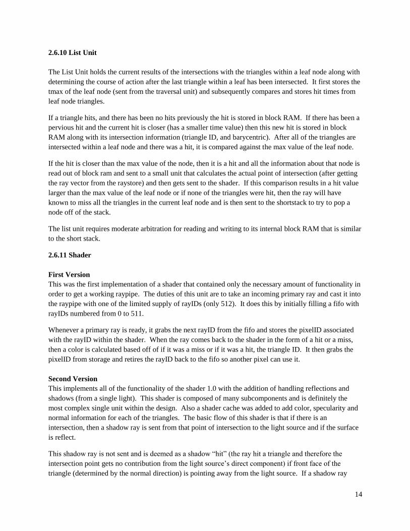
2.6.11 Shader
First Version
This was the first implementation of a shader that contained only the necessary amount of functionality in
order to get a working raypipe. The duties of this unit are to take an incoming primary ray and cast it into
the raypipe with one of the limited supply of rayIDs (only 512). It does this by initially filling a fifo with
rayIDs numbered from 0 to 511.
Whenever a primary ray is ready, it grabs the next rayID from the fifo and stores the pixelID associated
with the rayID within the shader. When the ray comes back to the shader in the form of a hit or a miss,
then a color is calculated based off of if it was a miss or if it was a hit, the triangle ID. It then grabs the
pixelID from storage and retires the rayID back to the fifo so another pixel can use it.
Second Version
This implements all of the functionality of the shader 1.0 with the addition of handling reflections and
shadows (from a single light). This shader is composed of many subcomponents and is definitely the
most complex single unit within the design. Also a shader cache was added to add color, specularity and
normal information for each of the triangles. The basic flow of this shader is that if there is an
intersection, then a shadow ray is sent from that point of intersection to the light source and if the surface
is reflect.
This shadow ray is not sent and is deemed as a shadow “hit” (the ray hit a triangle and therefore the
intersection point gets no contribution from the light source’s direct component) if front face of the
triangle (determined by the normal direction) is pointing away from the light source. If a shadow ray
15
retires back to the shadow (deemed as a hit or miss) or if a reflective ray (I clump primary ray in with
reflective ray) is deemed a miss, then the current color contribution is calculated and stored. This color
calculation requires large functional math units like normalization of vectors lots of multiplies, divides
and additions and is very expensive. If the ray is a reflective miss or if the ray reaches its max number of
reflections then it will calculate a final color, be converted into 16 bit color format and outputted to the
pixel buffer. This is a shortened simple description of this complex unit and this can be seen from the
diagram.
What follows is a schematic of the second shader and a description of a few specific modules within the
shader:

16
calc_direct:
The calculate direct illumination unit calculates the direct illumination at a given point of intersection on a
triangle. It takes as input the ambient color of light in the scene, the color of the light, whether or not the
ray is a shadow ray, whether or not the ray gets contribution from the point light source of the scene, the
normal vector for the triangle, the light position in the scene, and the point of intersection on the triangle.
If the ray passing through is a shadow ray and is in view of the scene’s point light source ( i.e., it’s a
“miss” because the shadow ray does not intersect with anything on its way to the light), then the direct
illumination at that point is given by the equation:
Directlight = K · (A + C·dot(N,L))
where K is the color of the triangle, A is the ambient color of light, C is the diffuse light color, N is the
normal of the triangle, and L is the normal from the point of intersection on the triangle to the light
source.
If the ray passing through is a shadow ray and is not in view of the scene’ point light
source, then its direct illumination at that point is given by
Directshadow = A · K
where A is the ambient color of the light in the scene and K is the color of the triangle. Otherwise, the
direct illumination for the triangle is simply the background color of the scene.
send_reflect:
The send reflection unit takes in a ray’s direction, point of intersection with a triangle, and that triangle’s
normal and creates the reflected ray to be sent into the raypipe.
The direction of the reflected ray is given by:
rayreflected = 2·N·dot(R,N) – R
where R is the incoming ray and N is the triangle’s normal. The origin of the reflected ray is given by the
previously calculated point of intersection on the triangle.
send_shadow:
The send shadow unit creates the shadow ray given a point of intersection on a triangle, that triangle’s
normal, and the position of the light.
Before sending the shadow ray into the ray pipe, the send shadow unit determines if the triangle is facing
the light source. If it is not facing the light source (that is, the dot product of the vector from the triangle
to the light and the triangle’s normal is negative), then it is reported to the shader that this triangle cannot
receive contribution from that light source. If the triangle is in the light, then it is sent into the raypipe to
determine if any other triangles preclude the light from hitting the current triangle.
color_convert:
17
The color convert unit converts a floating point color vector into a 16 bit color to be sent to the pixel
buffer.
Each floating point color vector is made of a red, green and blue component which determines the
contribution of their respective color. Valid values for each of these components are between 0 and 1,
inclusive.
In 16 bit color, 5 bits are reserved for each of red and blue. The remaining 6 bits are reserved for green.
The conversion from the floating point color vector to 16 bit color is then just a multiplication by 32 or 64
(64 for green, because it’s a 6 bit number), and then a conversion to integer format. Any decimal after
multiplication is truncated before conversion.
2.7 Pixel Buffer
The pixel buffer stores pixel data from the raypipe before it gets stored into the frame buffer in SRAM.
Because the frame buffer handler is actively reading out pixel data for the VGA output a large percentage
of the time, it is necessary to have this buffer. As it turned out, the contention for SRAM between the
pixel buffer storing data into memory vs. the frame buffer reading data out was a significant bottleneck in
our system. If the pixel buffer fills up, it must stall upward into the raypipe which can result in stalling the
entire system since the rate at which data gets written into SRAM is slower than the rate at which it gets
produced from the raypipe.
However, this problem is ultimately unavoidable because the pixel buffer can only be increased in size so
much. Ideally, it would be large enough to store the entire frame buffer in block RAM, but this would
defeat the purpose of using the SRAM (and would consume an extremely large percentage of our
available block RAM).
2.8 Frame Buffer Handler
The frame buffer handler has two main tasks:
Storage of rendered pixel data into SRAM
Retrieval of pixel data from SRAM for VGA output
We first developed a frame buffer capable of handling 24 bit color. We later decided, however, that 24 bit
color was unnecessary and that we would be better off using 16 bit color. Using 16 bit color provides two
large benefits: it simplifies the process of writing to and reading from memory since each memory
location stores 16 bits of data; and, it halves the number of writes and also decreases the number of reads
from memory (writing 24 bits of data requires two write operations where one of the writes only commits
one byte).
The original frame buffer handler is in frame_buffer_handler.sv while the simplified version is
in simple_frame_buffer_handler.sv.
18
2.9 Important Demos
During the development of our project, we created several important demos. Below are some of the
important ones.
2.9.1 sint demo
In order to test the PRG, camera control, and scene intersection unit, we put together a demo which
simply positioned a camera in front of a large scene bounding box. In this demo, when the user presses a
key to translate or rotate the camera, all of the units work in conjunction to display a rectangular prism on
the screen. This prism represents the scene bounding box.
I used the miss bit coming out of the scene intersection pipeline to determine whether or not to display a
color for the given ray. The effect of this coloring is a clearly distinguished rectangular prism which the
user can move around and rotate. This demo was very helpful for debugging and verifying the PRG,
camera controller, PS/2, and scene intersection units in synthesis.
2.9.2 t32
In order to test the memory request arbiter, the framebuffer handler, and the scene loader, we assembled a
demo which wrote an image over serial from the computer, stored that image into SDRAM and then read
it back out into the framebuffer.
The product of this demo was hardware that could read an image over serial and then display it over
VGA. The demo was very helpful for verifying that the memory request arbiter, scene loader, and
framebuffer handler all cooperated correctly.

19
3. Software
This section provides an explanation of the aspects of this project which were implemented in software.
The software side of this project may be found in the SOFTWARE directory in the repository.
3.1 Ray Tracer for 15-462
The computer science department of Carnegie Mellon University teaches an undergraduate course in
computer graphics (15-462). One of the projects of this course is to develop a basic ray tracer which can
render shadows, reflections, and refraction (more advanced features such as spatial data structures, anti-
aliasing, soft-shadows, and so on are not required). Because this project was already completed by two
members of our team and accomplishes several of the tasks required for scene file generation (such as
XML scene file and object file parsing), it was decided that this ray tracer should be used as a code base
for the software side of this project.
An added benefit of this decision is that certain features such as k-d tree construction can be tested in a
straight forward manner both in terms of functional correctness and performance (the latter can be
accomplished for k-d trees by modeling the cost of traversal and intersection with a simulated rendering
time).
3.2 K-d tree construction
K-d trees are a type of spatial data structure commonly used in ray tracers in order to accelerate rendering
by greatly reducing the number of required intersection tests. They work by partitioning the volume of a
scene into a hierarchy of sub-volumes according to the distribution of primitives throughout the scene. In
the case of k-d trees specifically, each level of the tree has associated with it a splitting plane which
partitions the node into two child nodes. The choice of where to make this split is usually determined by
some heuristic such as the surface area heuristic.
Below is an image of a low resolution model of the Standford bunny with the k-d tree algorithm applied.
Notice that empty sections of space contain large leaf nodes.
20
The ray tracer used in 15-462 uses meshes which each contain their own list of triangles. Rather than deal
with a complex data structure for meshes in hardware, we decided to simply combine all triangles from all
meshes into a single triangle list for simplicity (trade-offs for this decision are discussed in section 4). Our
k-d tree can thus deal with only triangles.
The code we use for constructing our K-d trees comes from the Physically Based Rendering project. The
source code for this project is freely available from http://www.pbrt.org/. Using the code from this project
was a very good idea as the algorithm is surely more finely tuned than something we could have devised
ourselves.
3.3 Scene file generation
The scene file contains several sections each of which are described in the following sections. In addition
to creating a binary file which is sent to the FPGA, the software raytracer also creates a corresponding
human readable file which is very helpful for interpreting the contents of the binary file.
3.3.1 K-d tree
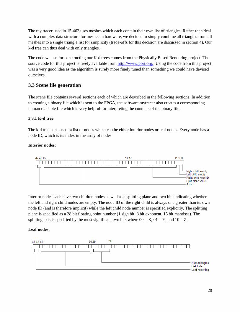
The k-d tree consists of a list of nodes which can be either interior nodes or leaf nodes. Every node has a
node ID, which is its index in the array of nodes
Interior nodes:
Interior nodes each have two children nodes as well as a splitting plane and two bits indicating whether
the left and right child nodes are empty. The node ID of the right child is always one greater than its own
node ID (and is therefore implicit) while the left child node number is specified explicitly. The splitting
plane is specified as a 28 bit floating point number (1 sign bit, 8 bit exponent, 15 bit mantissa). The
splitting axis is specified by the most significant two bits where 00 = X, 01 = Y, and 10 = Z.
Leaf nodes:
21
For leaf nodes, the most significant two bits are always 11 (which is what indicates it is a leaf node). The
“list index” is a number into an array of triangle IDs which specifies where its list of triangles begins. Six
bits are used to specify the length of this list i.e. the number of triangles in this leaf node.
3.3.2 Node Triangle Lists
Each leaf node may contain up to 63 triangles as specified by the “num triangles” field in the node. The
triangle IDs for each leaf node are specified in a large list of triangle IDs. Each leaf node will contain an
index into this list specifying where its list of triangle IDs begin. The list is simply dumped to the scene
file preceded by its byte count.
3.3.2 Triangle Transformation Matrices
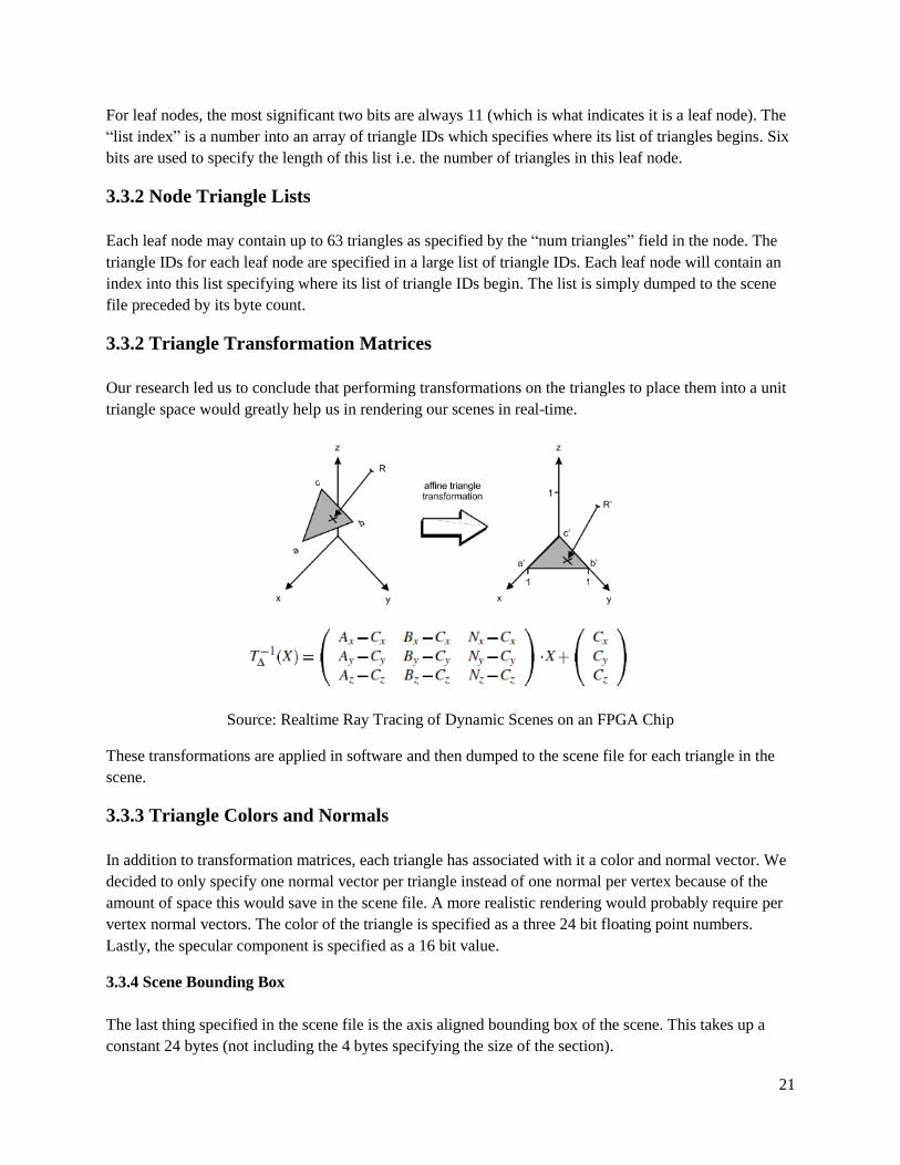
Our research led us to conclude that performing transformations on the triangles to place them into a unit
triangle space would greatly help us in rendering our scenes in real-time.
Source: Realtime Ray Tracing of Dynamic Scenes on an FPGA Chip
These transformations are applied in software and then dumped to the scene file for each triangle in the
scene.
3.3.3 Triangle Colors and Normals
In addition to transformation matrices, each triangle has associated with it a color and normal vector. We
decided to only specify one normal vector per triangle instead of one normal per vertex because of the
amount of space this would save in the scene file. A more realistic rendering would probably require per
vertex normal vectors. The color of the triangle is specified as a three 24 bit floating point numbers.
Lastly, the specular component is specified as a 16 bit value.
3.3.4 Scene Bounding Box
The last thing specified in the scene file is the axis aligned bounding box of the scene. This takes up a
constant 24 bytes (not including the 4 bytes specifying the size of the section).
22
4. Design Decisions
This section details many of the important design decisions made in this project providing explanations of
the alternatives considered, trade-offs for each, and the reason for the choices made.
Altera vs. Xilinx
A few weeks into the project after being extremely frustrated with the Xilinx tools we had available to us
we decided to switch to using an Altera FPGA. This was a very good decision. We did this because it
allowed us to use SystemVerilog as well as many simpler protocols such as VGA instead of HDMI and
serial instead of Ethernet. The toolchain was also more much pleasant to use and far less buggy. We
constantly ran into segfaults, licensing issues, and other issues with Xilinx. It was mostly smooth sailing
with Altera tools.
K-d tree vs. HBV
We decided to use K-d trees as the spatial data structure for our scenes. We knew of the existence of
hierarchical bounding volumes but we decided that it would be better to use k-d trees since we had very
good source code available for it from PBRT.
Triangles as the only primitives
We decided to only support triangles in our scenes since they have relatively inexpensive intersection
tests as contrasted with spheres for example which requires trigonometric functions. An arbitrary
geometry can be approximated using triangles so we felt that this was sufficient for our purposes.
No refraction
We knew from the beginning of the project that our goals were very ambitious and that we would be
lucky to get shadows and reflections working, so we decided early on that we should not plan for
refraction which is quite complex.
All matrix calculations done in software
Doing all of our matrix calculations in software means that we cannot have dynamic scenes (i.e. objects
moving in the scene) but we knew that we would not be able to achieve real-time performance if we tried
to do all of our matrix calculations in hardware. It was thus necessary to perform these calculations in
software and forfeit the possibility of dynamic scenes.
Single list of triangles vs. separate meshes
In software, our ray tracer has objects with meshes of triangles, each in their own coordinate space which
can be rotated, translated, and scaled independently of the other objects in the scene. We did not want to
have to deal with the complexity of dealing with meshes as distinct from individual triangles, so we
decided that we would join all of our meshes into a single, flat list of triangles.
No attenuation of light

23
Our software raytracer included equations for attenuation of light i.e. making the intensity of the light
contribution decrease as it moves farther away. The equations for this involved computationally
expensive equations, so we tested whether or not the scenes still looked realistic without it. From what we
observed, the light attenuation did not noticeably add to the realism of the scene so we decided to not
implement this in hardware.
Normals per face vs. per vertex
We also noticed that having a single normal per face vs. a separate normal vector per vertex in a triangle
did not impact the realism of several of our scenes. Thus, we decided to have one normal per face instead
of one normal per vector.
Triangles contain matrix data directly vs. vertex indices
When triangles share vertices, it saves space to have a triangle specify its vertices by indexing into a list
of vertices. This, however, requires an additional memory dereference so we decided to sacrifice the
savings in space for fewer dereferences (this is because our design is very sensitive to memory accesses).
Serial vs. Ethernet or SD Card
We decided to transfer scene data to the board using the serial port. This uses a much simpler protocol
than either Ethernet or the SD card. It does not require using a soft core processor, it simply requires some
basic FSMDs that we could write ourselves.
Caches use same addresses as corresponding units
The caches in our design use the same addresses as the units the store data for. For example, the triangle
cache knows how to interpret triangle IDs when indexing into its cache storage. When it sends a request
to the miss handler, this unit translates into actual DRAM addresses. (Remember, however, that we
ultimately did not include DRAM in our design.)
24
5. Testing Methodology
This project was very complex and required a very rigorous testing methodology. A few of the key testing
principles we tried to follow are:
Test each subunit individually before testing them together
Test as many cases as possible using a combination of random and directed test cases
Model the external stimuli as precisely as possible
When simulating, reduce protocol latencies to be as short possible for fast simulation
The first two principles are not very original but are particularly important. Our debugging time of the
entire system as a whole was relatively short thanks to the rigorous testing performed upon each subunit.
We were quite surprised with how easily we were able to get the entire system working with the little
amount of debugging required. The combination of random and directed test cases was particularly
important for the testing of the caches and ray store (the more complex versions of these modules).
It was particularly helpful to model the external stimuli as accurately as possible. For example, when
testing the XMODEM, it was helpful to actually write testbench tasks for sending bytes and blocks and to
use these tasks to simulate the transferring of entire files. This was used on the output side as well. A task
was used to capture the VGA data and dump it to a file so that we could view the images created by our
raytracer.
This was extremely useful as it allowed us to quickly confirm the functioning of our raytracer in a visual
way as opposed to painstakingly finding specific pixels in the waveform viewer and determine if the
hexadecimal values correspond to the correct colors that we should expect for that pixel. Maintaining a
precise testbench methodology which reflects the actual hardware as accurately as possible is essential for
effective testing.
The last principle on the list means that we reduced how long, for example, it takes to transfer a bit over
serial when simulating. We also reduced the time it takes to render the screen via VGA output. That is, we
defined the number of cycles to be much fewer in simulation (using `define SYNTH and `ifdef SYNTH to
easily switch between the two). This greatly reduced simulation time.
25
6. Results
This section provides a summary of the results of our project. We achieved a large portion of the initial
goals we set out to achieve. We successfully created scenes in software with k-d trees, designed a
mechanism for transferring the scenes to the board, created a very nice camera control interface, and
designed a very complex ray tracing pipeline which performed in real-time. We did not, however, get
shadows and reflections working by the demo date. We have all of the pipeline infrastructure necessary to
implement these features except for a finished shader unit.
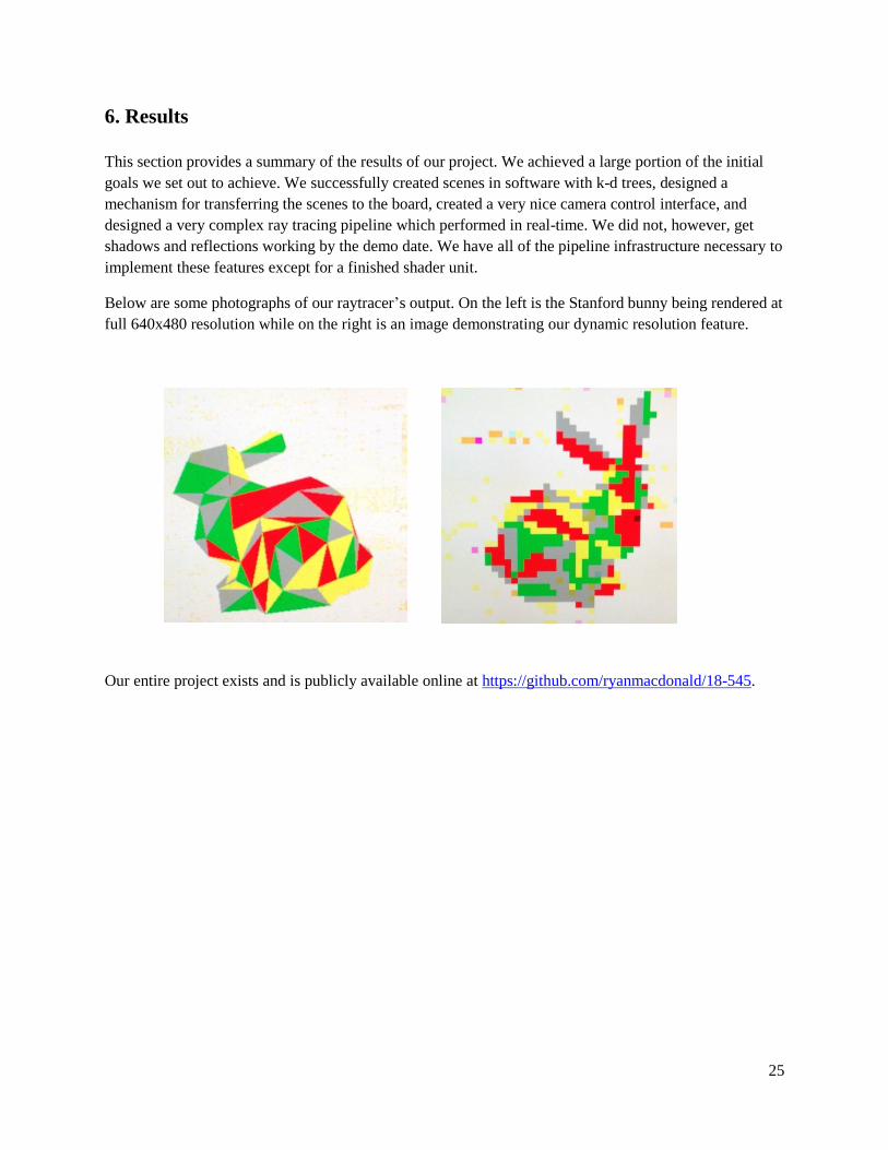
Below are some photographs of our raytracer’s output. On the left is the Stanford bunny being rendered at
full 640x480 resolution while on the right is an image demonstrating our dynamic resolution feature.
Our entire project exists and is publicly available online at https://github.com/ryanmacdonald/18-545.

26
7. Individual Comments
Ross Daly
Paul and I did a bulk of the research in the beginning of the project but I am the one who hammered out
all of the specifics of the raytracing algorithm that we were using this included all the specifics of the
shortstack algorithm and the “restart method” along with the gritty details of the KD tree traversal. I
architected the entirety of the final implementation of the raytracing pipeline (Paul and I initially
collaborated in creating some early versions that were not specific enough and had very major high level
issues unknown at the time). At this point I took on a sort of manager type role in the team and handed
out some of the units that Paul and Ryan were to design. Specifically I worked with Ryan to help come
up with some of algorithm and a high level design of the camera controller. I also assigned the scene
intersection unit, and many of the sub units within the shader 2.0 for Ryan to complete. I came up with
the concept of the raystore after realizing that pipeing the entire ray vector through every stage of the
pipeline would be wasting hardware and gave this unit to Paul to design. I also collaborated with Paul to
come up with a feature spec of the caches along with assisted in the design process of the cache. I
designed and coded and tested the traversal unit, the intersection unit (an early version used in
midsemester demo and the final version), the list unit, the shortstack, and the shader 1.0.
I fully designed and integrated shader 2.0 with the help of Ryan for coding and testing the major
subunits. I integrated and debugged the raypipe with Paul helping as well. I also formulated a design
methodology for dealing with unstallable sections of the pipeline (fifo + “smart” sideband data path)
along with the exact valid/stall protocol for interfacing between major units. I introduced an original
methodology for ease in designing math pipelines that had throughputs of 1/3 cycles. I designed some
library components like arbiters, fifos and “smart” buffers that would follow the valid/stall protocol while
buffering the stall signal that were used throughout all of the units. On top of this I offered advice and
collaboration with Paul and Ryan throughout almost every aspect and level of the project.
There were many things that I learned from this project from design style to people skills. I now have a
much greater appreciation for companies that accomplish projects thousands of times more complicated
than our own and all the problems that they must go through and find solutions to. It was very interesting
and useful to see a project go from research to final product. I learned that Paul and Ryan were the
perfect team members for this project. I would bet that with anyone else on our team and the same
project, the necessary work would not have been completed. We all had a do or die mindset which was a
major reason that we were successful.
Another reason we were successful was due to the fact that we did not have to debug other people’s
horrible software or hardware code like the other teams did. I am really glad that we chose a real design
project as we could all actually use our skills to implement a project. I learned a lot from all of the minor
arguments that Paul and I got into about things not even necessarily related to our project. But most
importantly we learned that despite different opinions and ideas on anything ranging from design
methodology to exam study techniques, there is always a way to resolve and move on.
As advice to future 545 students, be very careful when picking your teams and your project. Make sure
that the intended effort output of all team members match your own. I would strongly advise going
against the “normal” 545 project choosing process and choose an actual design project that you define for
yourself. If integrating and debugging badly coded programs and processors that you did not write
yourself sounds appealing to you, then by all means pick that type of project. For our group, we all loved
RTL design, worked well together and came out with a kick ass project because of it.

27
Paul Kennedy
This was an extremely ambitious project. It was also a very fun and satisfying project. Any group that
attempts a project of this kind, however, should know how much work is involved. Of my four and a half
years at CMU, this semester had the fewest number of units I have taken. I was also the busiest I've ever
been this semester. It required being in the lab each and every day, sacrificing sleep, dropping a class,
consuming over a dozen 5 hour energies, sleeping in the lab, and having virtually no social life. In
hindsight, it would probably have been better to pick a less ambitious project. On the other hand, it has
given me something to talk about during job interviews. Many of the things I worked on for this project
involve concepts which relate to those used in actually computer architecture including: checkpoint
mechanisms, valid-stall protocols, identifying pipeline bottlenecks, dealing with circuit timing, designing
arbiters, and designing and testing caches. I also learned several things about the SystemVerilog language
including generate blocks and a number of handy testbench concepts.
The modules on which I worked include: the scene loader, the cache, the raystore, the XMODEM
module, and the frame buffer handler. I also created most of the top modules for demoing the entire
system and wrote many of the testbench tasks. I also completely handled the software side of this project.
This included adapting the pbrt source code for generating K-d trees as well as creating a scene file to be
transferred over serial. I invested a lot of time discussing initial architecture designs with Ross though
once RTL coding began, he took over this responsibility.
My main piece of advice to future groups is to start with simple designs first and then move to more
complex designs once those have been made to work. Many of the modules we designed had a large
degree of complexity to them which consumed much of our time and then had to be simplified. For
example, the frame buffer handler was initially designed to handler 24 bit color. This made the frame
buffer handler considerably more complex since each pixel consumes 1.5 memory locations in SRAM.
Access patterns for both reading and writing were more complex due to this. Our caches were also made
extremely simple once DRAM was abandoned. We also changed to using a very simple raystore. A very
significant amount of time was invested into each of these modules which could have been spent usefully
on other things toward the end of the project.
Of course, it was difficult to predict that we would abandon DRAM, but it would have been better to get
our simple modules working first with plans on how to replace them with complex modules than to have
to go back and cut out our complexity at the end. This was not only a waste of time, but was pretty
demoralizing.
Another issue we dealt with was very early on: we struggled with trying to get Xilinx tools to work and to
use SystemVerilog. We also struggled with getting the Xilinx IP to synthesize. We decided to switch to
using an Altera board which was a much easier process. It would have been much better if we had made
this decision earlier on. Future groups should keep this alternative in mind and not hesitate to switch to a
different platform if it looks like it would be in their interests.
I think that we have a very solid code base off of which to work if any future groups wish to build upon
our project. It is also quite module allowing for the borrowing of various parts for other projects. Inside
our library.sv we have many small components which other groups may find useful such as fifo and
pipe_valid_stall.

28
I noticed that many (many) previous groups said that they struggled with "team dynamics". We did not
face this issue. All three members of this group were extremely reliable, skilled, and hard-working. We
each invested many hours and were (on the whole) very pleasant to each other. The main issue we
struggled with was getting DRAM to cooperate (which it did not). We could have arrived at a more
satisfying end-result if we had not wasted so much time on complexity that required DRAM to work.
Again, overall this was very satisfying and educational project but future groups should know how much
of a sacrifice is required to achieve something of this magnitude.
29
Ryan Macdonald
At the beginning of the semester, I spent all of my time researching the raytracing algorithm, reading
about FPGA implementations, and mucking around with the Xilinx/Vivado toolchain. About a month into
the semester, it became obvious that nothing in the Xilinx toolchain (including Vivado, which is intended
for use with SystemVerilog) was compatible with SystemVerilog and we switched to using the Altera
DE2-115 boards.
When we made the decision to switch from Xilinx to Altera, I immediately started working on the
memory request arbiter. The core of the memory request arbiter is an Altera SDRAM controller IP core,
and so I spent a lot of time trying to get that core to work with simple reads and writes. Eventually, after a
lot of research and tweaking parameters in Altera’s Qsys IP generator, I was able to get successful reads
and writes from the SDRAM. I then wrote a wrapper for this controller which supports arbitrary length
reads and writes from an arbitrary number of clients.
Throughout my time working on the memory request arbiter, I also started building the primary ray
generator and the camera controller. Before the memory request arbiter was done, I had finished a basic
primary ray generator which was used in the midsemester demo.
By about a week and a half after the midsemester demo, I had finished the memory request arbiter,
primary ray generator, and camera controller. At this point, Paul and I put together a simple demo to
verify that the memory request arbiter was working with the scene loader. When this was done and
debugged, I started working on the scene intersection unit.
When I had finished the scene intersection unit, I decided to put together a demo to verify that it worked
with the primary ray generator, camera controller, PS/2 parser, and framebuffer handler in synthesis. The
demo used all of these units to render a rectangular prism on the screen. A PS/2 keyboard could be used
to translate the camera in any direction within this simple scene.
When I had finished this demo and everything was working, I added dynamic resolution and ray
packeting to the primary ray generator as well as dynamic translation speed and camera rotation to the
camera controller. By the time I had started working on all of that, we had two weeks until the final demo
and so I also started working on some units that would be needed for a more complicated shader. Over the
course of the last two weeks I wrote the color converter, the direct illumination calculator, the shadow ray
unit, and the reflection ray unit.
While I was doing all of this, Ross and Paul spent a lot of time putting together and debugging a raytracer
using a simple shader which determined color solely based on the triangle’s ID. As they were debugging,
they found that Altera’s SDRAM controller was not functioning properly. We spent two days attempting
to constrain the SDRAM controller for timing, a solution which had worked in the past, but nothing
seemed to work. With about a week left, we decided it would be best to just use block RAM instead, and
so we scrapped the memory request arbiter and SDRAM.
In the last week I spent all of my time working on units in the shader. Ross and I were debugging the new
shader, which would’ve supported shadows and reflections instead of simple coloring, until the last
minute. We never finished it and we ended up having to demo the raytracer which used a simple shader.
30
I found this course to be extremely rewarding for a number of reasons. I found that working on a project
with a tangible result was much more fulfilling than projects which only worked in simulation. In
particular, it was really cool to see all of our hard work come together and pay off every few weeks when
we put together intermediate demos.
Whether it was getting the initial two triangles to render at the midsemester demo or the final raytracer
working, I was always really proud of what we had accomplished. This course was extremely valuable for
learning about FPGA design, debugging, and synthesis. Over the course of the semester, we encountered
problems and constraints that were completely foreign and I believe we learned a lot from having to
research and debug them.
It was a very rewarding experience to work with and learn from Paul and Ross over the course of the
semester. I think this course was invaluable for learning about team dynamics and work scheduling.
To future students in this course, I recommend that you spend a lot of time thinking about what project
you would like to pursue. It’s okay to be ambitious, but I think a little research goes a long way when
you’re beginning to come up with ideas for potential projects. Additionally, I think one thing that helped a
lot in this class was to iterate from less complicated designs to more complicated designs. The units
which made up our initial demos were completely different from the units which went into the final demo.
I think this mindset of iterating on a design was really beneficial, especially because it guarantees some
kind of demo and sanity check at any given point during the semester.

31
8. Appendix
This section includes details on the protocols we used in this project.
7.1 Serial
The serial protocol has a variety of formats, but the one we used had the following specifications:
8 data bits
1 start bit (a logic low)
1 stop bit (a logic high)
No parity bit
We transferred data at a baud rate of 115,200. All of our parameters may be found in
COMMON/defines.sv under the section “Defines for XMODEM”.
NOTE: to any group which may use serial communication, ensure that you eliminate meta-stability of the
signal by passing the input pin through a couple flip flops before using it. We ran into issues with this.
Also note that it is best to sample the data in the middle of the bit’s transfer period. This can be done by
detecting the negative edge of the signal and then waiting an appropriate number of cycles before
sampling the data.
7.2 XMODEM
The XMODEM protocol is a very simple protocol used in serial communication. It transfers data in 128
byte blocks which are preceded by a SOH byte (0x01), a one byte block number, a one byte bitwise
inverse of that block number, and followed by a one byte checksum of the data (a sum of the 128 data
bytes in which carry bits are ignored).
Transfer begins when the FPGA sends a NAK (0x15) to the computer. The computer will then begin
sending blocks starting with a block number of 1. After each validly received block, the FPGA will send
back an ACK (0x06). If at any point a block contains an error (an invalid block number or checksum), the
FPGA will send back a NAK. An invalid block number is any block number which is not either equal to
or one greater than the previous block number (the protocol allows for the same block to be sent twice in
the case that the ACK from the receiver gets garbled). If the block number reaches 127, it goes back to 1.
After all data blocks have been transferred, an EOT (0x04) byte is sent.
More details on the XMODEM protocol (including time outs) can easily be found with a Google search
for XMODEM.
32
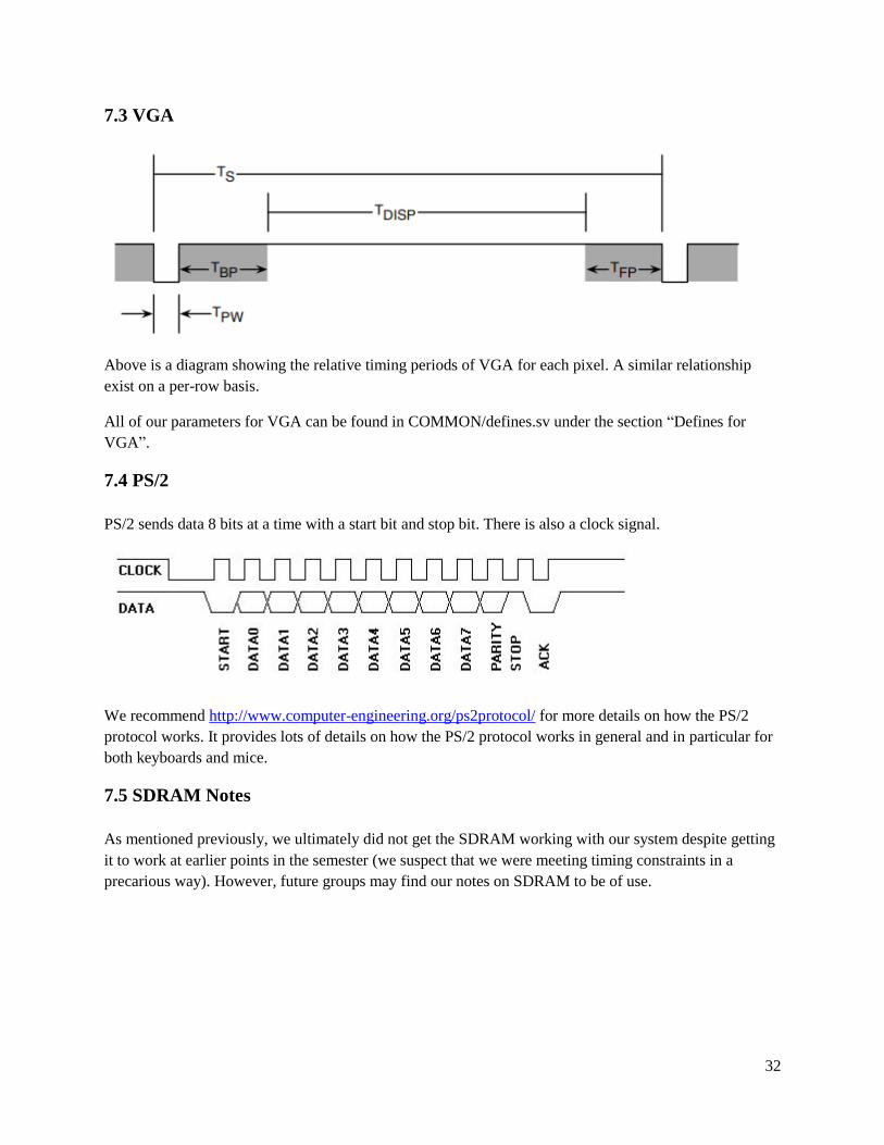
7.3 VGA
Above is a diagram showing the relative timing periods of VGA for each pixel. A similar relationship
exist on a per-row basis.
All of our parameters for VGA can be found in COMMON/defines.sv under the section “Defines for
VGA”.
7.4 PS/2
PS/2 sends data 8 bits at a time with a start bit and stop bit. There is also a clock signal.
We recommend http://www.computer-engineering.org/ps2protocol/ for more details on how the PS/2
protocol works. It provides lots of details on how the PS/2 protocol works in general and in particular for
both keyboards and mice.
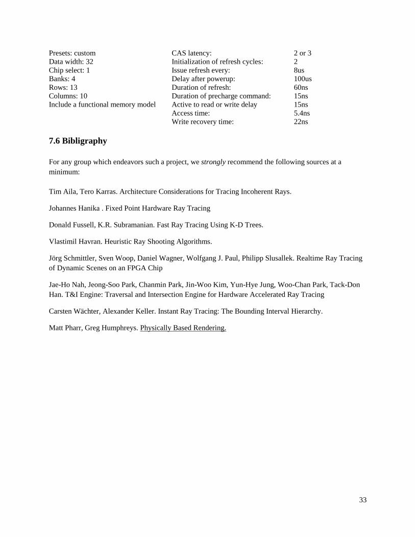
7.5 SDRAM Notes
As mentioned previously, we ultimately did not get the SDRAM working with our system despite getting
it to work at earlier points in the semester (we suspect that we were meeting timing constraints in a
precarious way). However, future groups may find our notes on SDRAM to be of use.
33
Presets: custom
Data width: 32
Chip select: 1
Banks: 4
Rows: 13
Columns: 10
Include a functional memory model
CAS latency:
Initialization of refresh cycles:
Issue refresh every:
Delay after powerup:
Duration of refresh:
Duration of precharge command:
Active to read or write delay
Access time:
Write recovery time:
2 or 3
2
8us
100us
60ns
15ns
15ns
5.4ns
22ns
7.6 Bibligraphy
For any group which endeavors such a project, we strongly recommend the following sources at a
minimum:
Tim Aila, Tero Karras. Architecture Considerations for Tracing Incoherent Rays.
Johannes Hanika . Fixed Point Hardware Ray Tracing
Donald Fussell, K.R. Subramanian. Fast Ray Tracing Using K-D Trees.
Vlastimil Havran. Heuristic Ray Shooting Algorithms.
Jörg Schmittler, Sven Woop, Daniel Wagner, Wolfgang J. Paul, Philipp Slusallek. Realtime Ray Tracing
of Dynamic Scenes on an FPGA Chip
Jae-Ho Nah, Jeong-Soo Park, Chanmin Park, Jin-Woo Kim, Yun-Hye Jung, Woo-Chan Park, Tack-Don
Han. T&I Engine: Traversal and Intersection Engine for Hardware Accelerated Ray Tracing
Carsten Wächter, Alexander Keller. Instant Ray Tracing: The Bounding Interval Hierarchy.
Matt Pharr, Greg Humphreys. Physically Based Rendering.