Embed Size (px)
Citation preview
Technical Assignment 3 Mechanical Systems Existing Conditions Evaluation
City of Hope: Amini Medical Center Duarte, CA Christopher Bratz Pennsylvania State University Architectural Engineering Mechanical Option Faculty Advisor: Dr. Jelena Srebric November 21st, 2008
Mechanical Systems Existing Conditions Evaluation 2
Table of Contents Executive Summary…………………………………………………………………….3 Project Overview………………………………………………………………………...4 Building Overview.………………………………………………………………4
Mechanical Systems Overview.…………………….…………………………4 Mechanical Systems Design Influences………….………………………………...5
Owner/Occupancy Requirements..……………………………………………5 Site Influences…………………..…………………….…………………………5 Monetary Influences………………….…………………………………………5 Design Indoor/Outdoor Conditions………………………………………….…6 Code Requirements..…………..…………………….…………………………6 Ventilation Requirements……...…………………….…………………………6 Discussion…………..…………..…………………….…………………………7
Mechanical Systems Description…………………….………….…………………...7
Heating Plant & Building Heating System.……………………………………7 Cooling Plant & Building Cooling System.……………….……………………7 Air Distribution Systems..…………….…………………………………………8 Exhaust Air Systems….………..…………………….…………………………9 Control Features…………………..………………………………………….…9
Lost Rentable Space…………………………………….……………………………...12 Mechanical Systems First Cost………….…………………………………………...13 Load & Energy Results………………………………….……………………………...14
Load Results Overview…………………….……………………………………14 Energy Results Overview………………….……………………………………14 Discussion………………..………………………………………………………15
System Critique…….…………………………………………………………………....15
Central Plant………….…………………….…………………………………….16 Building Equipment……..………………….……………………………………16
References……......……………………………………………………………………....17 APPENDIX A – Vicinity Map & Air Distribution Maps APPENDIX B – Flow Diagrams APPENDIX C – Equipment Schedules APPENDIX D – Unit Diagrams APPENDIX E – DPR Mechanical Cost Estimation
________________________________________________________________________City of Hope: Amini Medical Center Duarte, California
Mechanical Systems Existing Conditions Evaluation 3
Executive Summary The focus of this report is to provide an in depth look at the mechanical systems for the Amini Medical center and provide a personal critique. This evaluation will provide a brief overview of the project then discuss aspects that influenced the current design. The current system will then be described in detail with references to maps and diagrams that will act as visual aides. After the Amini Center system has been described, the size, load, and energy impact of the system will be discussed and evaluated. To conclude the report, a critique of the system has been provided. Overall, the Amini Center’s Mechanical system seems to meet all the requirements of the building. It is a versatile system which provides ample control to keep people comfortable in the zones that were created. The system also employs energy saving features to minimize its effect on the environment. Overall, I believe the Amini Center’s design to be a very good one.
________________________________________________________________________City of Hope: Amini Medical Center Duarte, California
Mechanical Systems Existing Conditions Evaluation 4
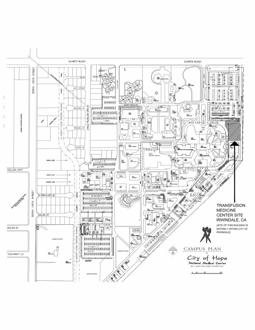
Project Overview Building Overview The Amini Medical Center is the newest addition to the City of Hope campus community located in the Los Angeles, CA suburbs. The community’s main functions include cancer research, treatment and education. The Amini facility’s role as a part of this community includes blood collection, analysis, processing, transfusion, and storage. To accommodate the building functions, the Amini Center is designed as a 3 story, 60,000 square foot complex which sits on the East side of campus. (Refer to page 1 of Appendix A for a vicinity map) The floors of the facility are broken down as follows:
Amini Center 1st Floor Breakdown
Room Types Area (ft2) Function
Stem Cell Lab/ Support Area 2,500 Biomedical Research and testing
Cryogen Freezer 1,700 Stem Cell / Blood storage
Blood Processing Area/ Freezers 5,300 Blood Processing, testing, logistic work, & temp. storage
Office Space 1,650 Administrative duties
Break Room 320 Making food/ eating
Mechanical/Electrical/IT 1,250 Equip Rooms/Data Centers
Transition/Storage/Restroom 5,800 Storage and walk through areas
Amini Center 2nd Floor Breakdown
Room Types Area (ft2) Function
Blood Donation / Transfusion Bays 6,200 Extracting/giving blood from/to donors/patients
Office Space 4,500 Administrative duties
Reception Area 540 Waiting and filling out paperwork
Conference Room 620 Meetings/Training
Break Room 520 Making food/ eating
Mechanical/Electrical/IT 450 Equip Rooms/Data Centers
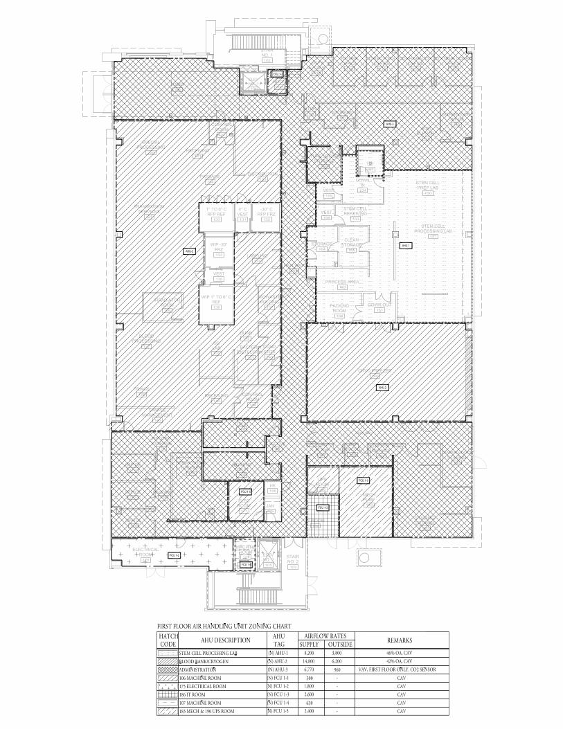
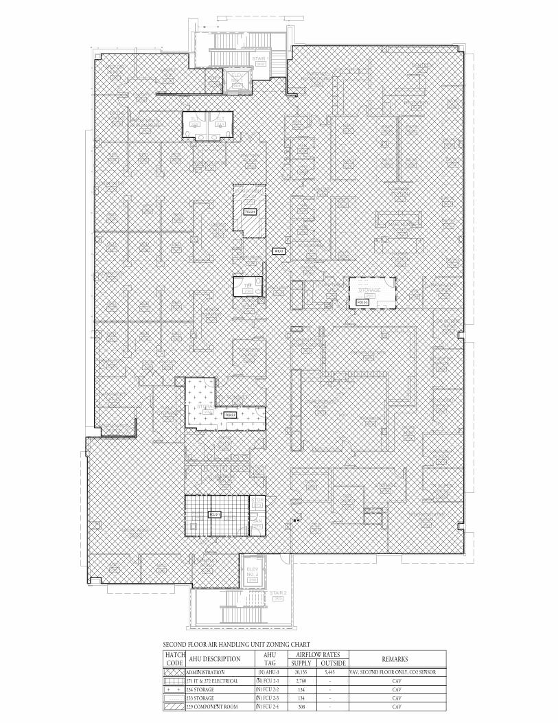
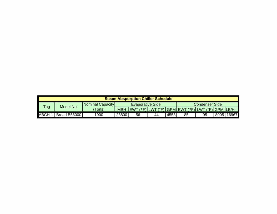
Transition/Storage/Restroom 5,550 Storage and walk through areas The third floor of the Amini complex is scheduled to become office space in the future; however, due to the strict budget constraints, the third floor fit-out was not included with this construction submission and, therefore, was not incorporated in this evaluation. Mechanical Systems Overview The cooling for this building is provided by a chilled water system while the heating loads are met by converting steam to hot water (HW) for use by HW coils in the air systems. The bulk of the 1st and 2nd floors of the Amini Center are served by three custom, water cooled, Air Handling Units (AHUs) located on the roof. Small horizontal, water cooled, Fan Coil Units (FCUs), located in the ceiling plenums, serve the remaining areas not being served by an AHU. The areas served by the AHUs are broken down as follows: AHU-1 serves the Stem Cell Lab and support areas located on the 1st floor. AHU-2 serves the Blood Processing area and the Cryogen Freezer on the 1st floor. All remaining spaces on the 1st and 2nd floors are served by AHU-3. Refer to pages 2 and 3 of Appendix A for the outline of AHUs and FCUs service areas. A further
________________________________________________________________________City of Hope: Amini Medical Center Duarte, California
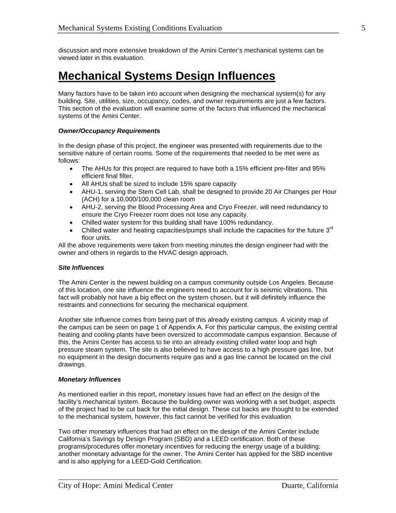
Mechanical Systems Existing Conditions Evaluation 5 discussion and more extensive breakdown of the Amini Center’s mechanical systems can be viewed later in this evaluation.
Mechanical Systems Design Influences Many factors have to be taken into account when designing the mechanical system(s) for any building. Site, utilities, size, occupancy, codes, and owner requirements are just a few factors. This section of the evaluation will examine some of the factors that influenced the mechanical systems of the Amini Center. Owner/Occupancy Requirements In the design phase of this project, the engineer was presented with requirements due to the sensitive nature of certain rooms. Some of the requirements that needed to be met were as follows:
• The AHUs for this project are required to have both a 15% efficient pre-filter and 95% efficient final filter.
• All AHUs shall be sized to include 15% spare capacity • AHU-1, serving the Stem Cell Lab, shall be designed to provide 20 Air Changes per Hour
(ACH) for a 10,000/100,000 clean room • AHU-2, serving the Blood Processing Area and Cryo Freezer, will need redundancy to
ensure the Cryo Freezer room does not lose any capacity. • Chilled water system for this building shall have 100% redundancy. • Chilled water and heating capacities/pumps shall include the capacities for the future 3rd
floor units. All the above requirements were taken from meeting minutes the design engineer had with the owner and others in regards to the HVAC design approach. Site Influences The Amini Center is the newest building on a campus community outside Los Angeles. Because of this location, one site influence the engineers need to account for is seismic vibrations. This fact will probably not have a big effect on the system chosen, but it will definitely influence the restraints and connections for securing the mechanical equipment. Another site influence comes from being part of this already existing campus. A vicinity map of the campus can be seen on page 1 of Appendix A. For this particular campus, the existing central heating and cooling plants have been oversized to accommodate campus expansion. Because of this, the Amini Center has access to tie into an already existing chilled water loop and high pressure steam system. The site is also believed to have access to a high pressure gas line, but no equipment in the design documents require gas and a gas line cannot be located on the civil drawings. Monetary Influences As mentioned earlier in this report, monetary issues have had an effect on the design of the facility’s mechanical system. Because the building owner was working with a set budget, aspects of the project had to be cut back for the initial design. These cut backs are thought to be extended to the mechanical system, however, this fact cannot be verified for this evaluation. Two other monetary influences that had an effect on the design of the Amini Center include California’s Savings by Design Program (SBD) and a LEED certification. Both of these programs/procedures offer monetary incentives for reducing the energy usage of a building; another monetary advantage for the owner. The Amini Center has applied for the SBD incentive and is also applying for a LEED-Gold Certification.
________________________________________________________________________City of Hope: Amini Medical Center Duarte, California
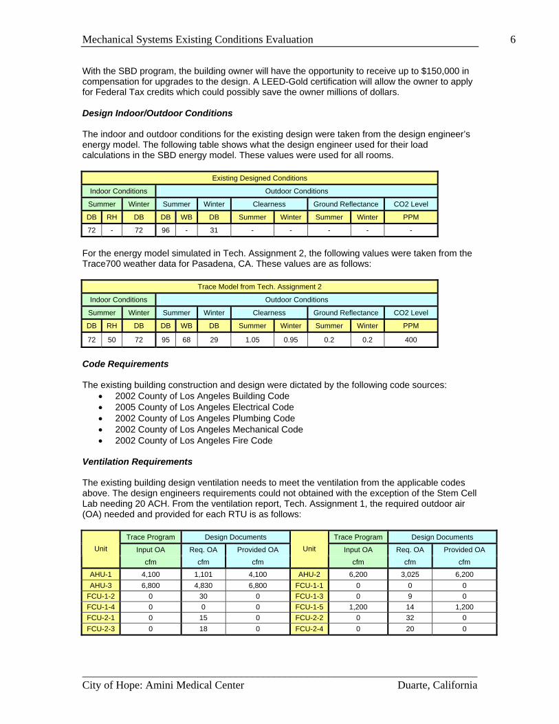
Mechanical Systems Existing Conditions Evaluation 6 With the SBD program, the building owner will have the opportunity to receive up to $150,000 in compensation for upgrades to the design. A LEED-Gold certification will allow the owner to apply for Federal Tax credits which could possibly save the owner millions of dollars. Design Indoor/Outdoor Conditions The indoor and outdoor conditions for the existing design were taken from the design engineer’s energy model. The following table shows what the design engineer used for their load calculations in the SBD energy model. These values were used for all rooms.
Existing Designed Conditions
Indoor Conditions Outdoor Conditions
Summer Winter Summer Winter Clearness Ground Reflectance CO2 Level
DB RH DB DB WB DB Summer Winter Summer Winter PPM
72 - 72 96 - 31 - - - - -
For the energy model simulated in Tech. Assignment 2, the following values were taken from the Trace700 weather data for Pasadena, CA. These values are as follows:
Trace Model from Tech. Assignment 2
Indoor Conditions Outdoor Conditions
Summer Winter Summer Winter Clearness Ground Reflectance CO2 Level
DB RH DB DB WB DB Summer Winter Summer Winter PPM
72 50 72 95 68 29 1.05 0.95 0.2 0.2 400
Code Requirements The existing building construction and design were dictated by the following code sources:
• 2002 County of Los Angeles Building Code • 2005 County of Los Angeles Electrical Code • 2002 County of Los Angeles Plumbing Code • 2002 County of Los Angeles Mechanical Code • 2002 County of Los Angeles Fire Code
Ventilation Requirements The existing building design ventilation needs to meet the ventilation from the applicable codes above. The design engineers requirements could not obtained with the exception of the Stem Cell Lab needing 20 ACH. From the ventilation report, Tech. Assignment 1, the required outdoor air (OA) needed and provided for each RTU is as follows:
Trace Program Design Documents Trace Program Design Documents
Input OA Req. OA Provided OA Input OA Req. OA Provided OA Unit
cfm cfm cfm
Unit
cfm cfm cfm
AHU-1 4,100 1,101 4,100 AHU-2 6,200 3,025 6,200 AHU-3 6,800 4,830 6,800 FCU-1-1 0 0 0
FCU-1-2 0 30 0 FCU-1-3 0 9 0 FCU-1-4 0 0 0 FCU-1-5 1,200 14 1,200 FCU-2-1 0 15 0 FCU-2-2 0 32 0 FCU-2-3 0 18 0 FCU-2-4 0 20 0
________________________________________________________________________City of Hope: Amini Medical Center Duarte, California
Mechanical Systems Existing Conditions Evaluation 7 In the table above, the required OA shown is in accordance with ASHRAE 62.1-2007, not the applicable codes the building was designed with. Discussion The many factors here are just some of the influences dug up for the Amini Medical Center project. There are many other factors that were, and could have been, taken into account in the actual design of the mechanical system. One such factor is the heat load of the many pieces of equipment located throughout this facility. Either way, the influences listed here can be viewed as the key elements in the design for the existing mechanical system.
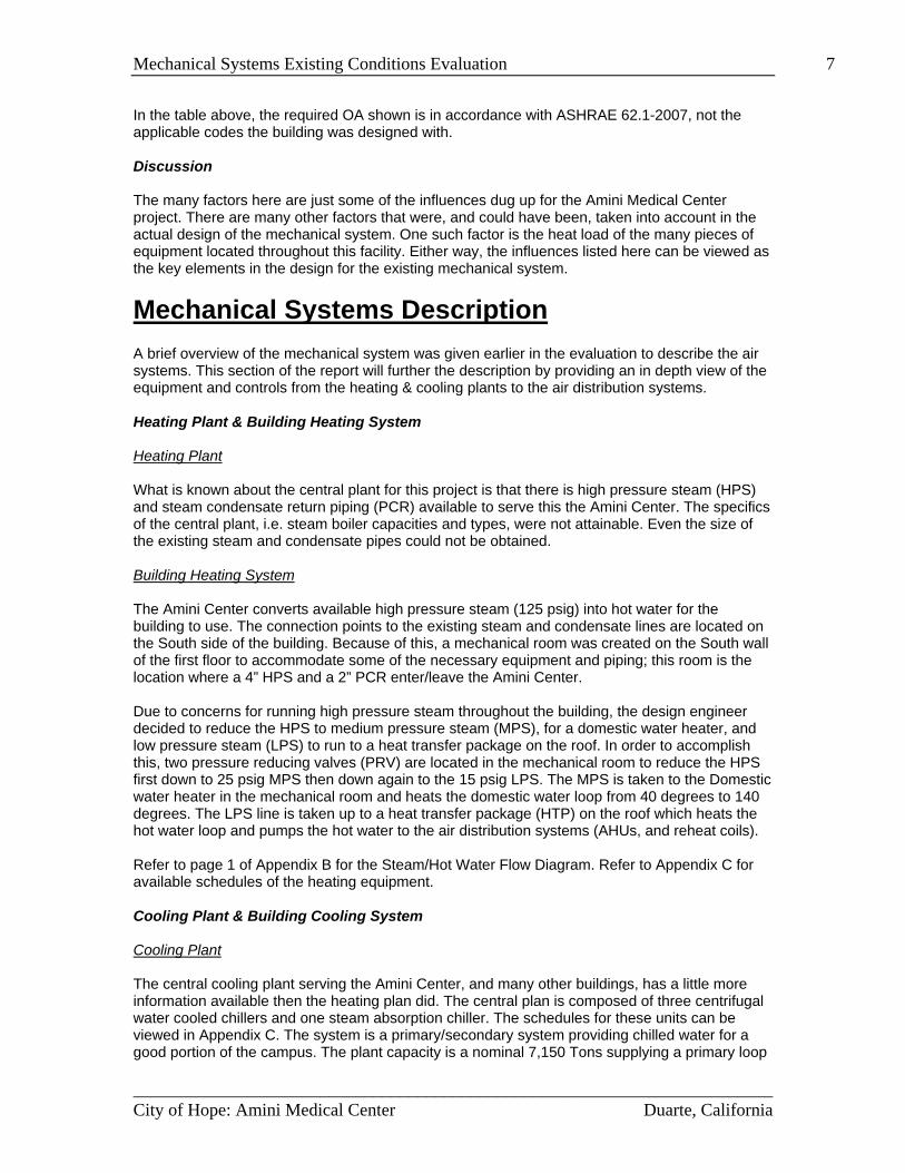
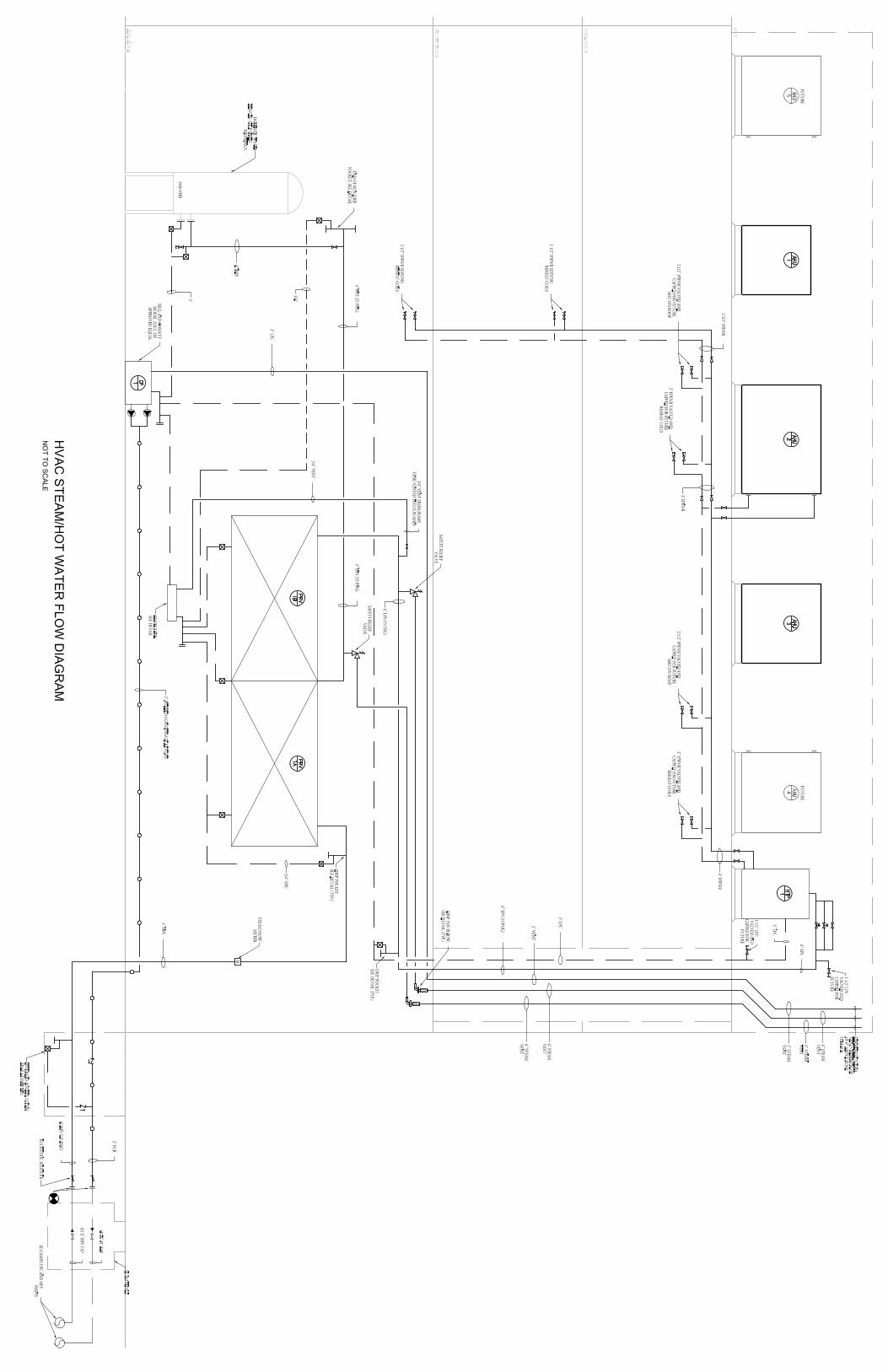
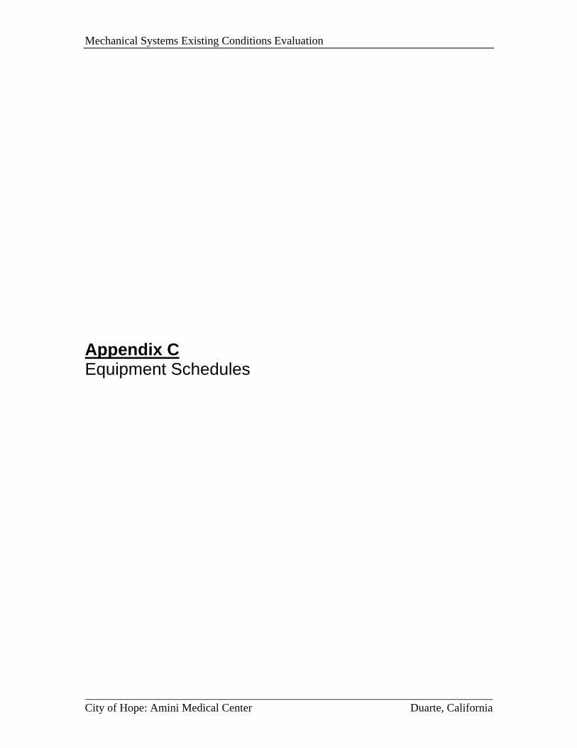
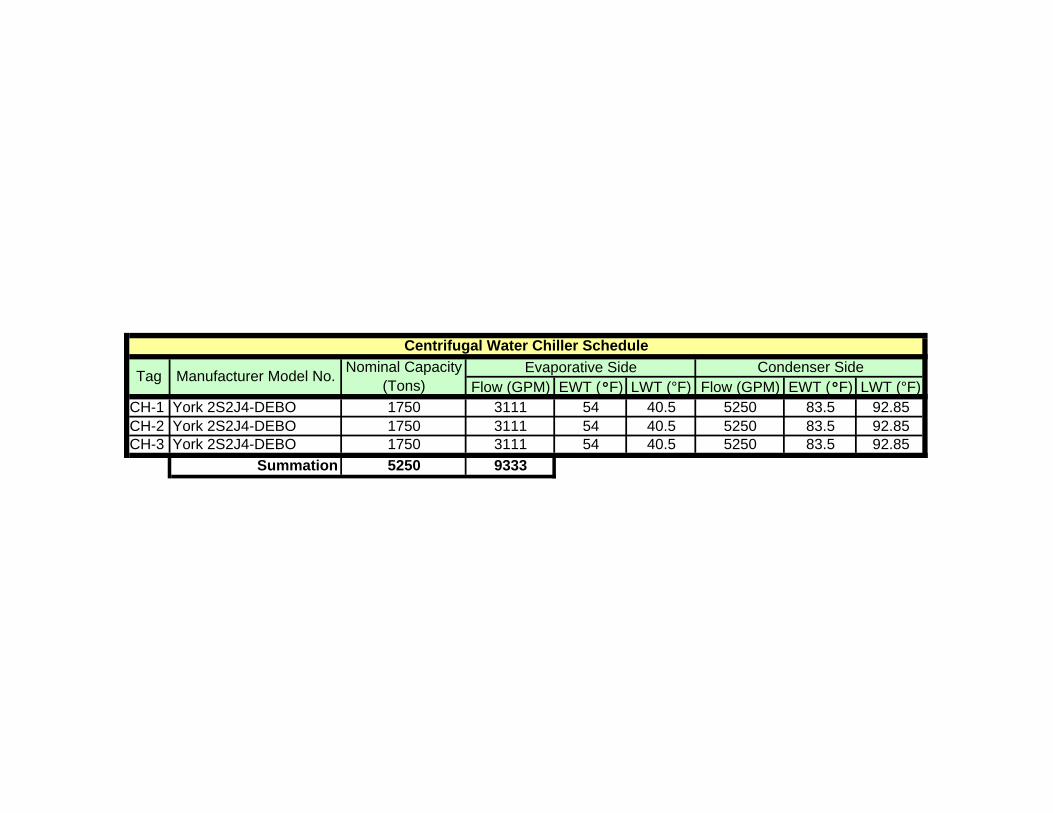
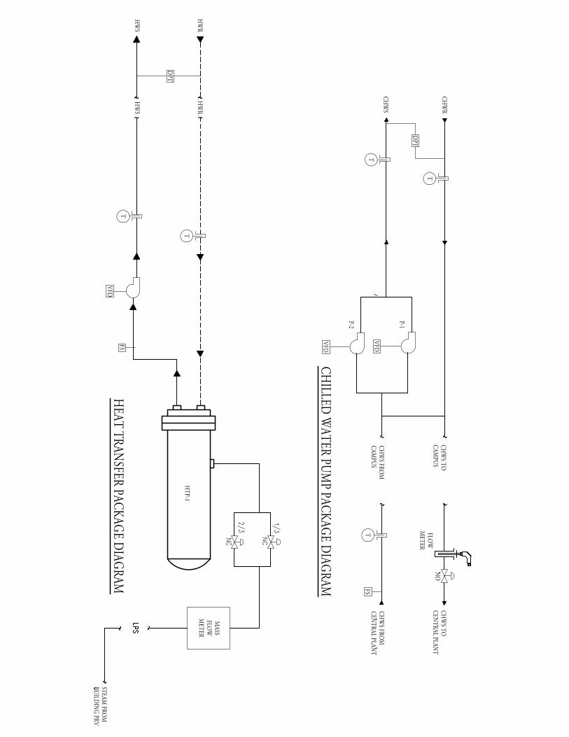
Mechanical Systems Description A brief overview of the mechanical system was given earlier in the evaluation to describe the air systems. This section of the report will further the description by providing an in depth view of the equipment and controls from the heating & cooling plants to the air distribution systems. Heating Plant & Building Heating System Heating Plant What is known about the central plant for this project is that there is high pressure steam (HPS) and steam condensate return piping (PCR) available to serve this the Amini Center. The specifics of the central plant, i.e. steam boiler capacities and types, were not attainable. Even the size of the existing steam and condensate pipes could not be obtained. Building Heating System The Amini Center converts available high pressure steam (125 psig) into hot water for the building to use. The connection points to the existing steam and condensate lines are located on the South side of the building. Because of this, a mechanical room was created on the South wall of the first floor to accommodate some of the necessary equipment and piping; this room is the location where a 4” HPS and a 2” PCR enter/leave the Amini Center. Due to concerns for running high pressure steam throughout the building, the design engineer decided to reduce the HPS to medium pressure steam (MPS), for a domestic water heater, and low pressure steam (LPS) to run to a heat transfer package on the roof. In order to accomplish this, two pressure reducing valves (PRV) are located in the mechanical room to reduce the HPS first down to 25 psig MPS then down again to the 15 psig LPS. The MPS is taken to the Domestic water heater in the mechanical room and heats the domestic water loop from 40 degrees to 140 degrees. The LPS line is taken up to a heat transfer package (HTP) on the roof which heats the hot water loop and pumps the hot water to the air distribution systems (AHUs, and reheat coils). Refer to page 1 of Appendix B for the Steam/Hot Water Flow Diagram. Refer to Appendix C for available schedules of the heating equipment. Cooling Plant & Building Cooling System Cooling Plant The central cooling plant serving the Amini Center, and many other buildings, has a little more information available then the heating plan did. The central plan is composed of three centrifugal water cooled chillers and one steam absorption chiller. The schedules for these units can be viewed in Appendix C. The system is a primary/secondary system providing chilled water for a good portion of the campus. The plant capacity is a nominal 7,150 Tons supplying a primary loop
________________________________________________________________________City of Hope: Amini Medical Center Duarte, California
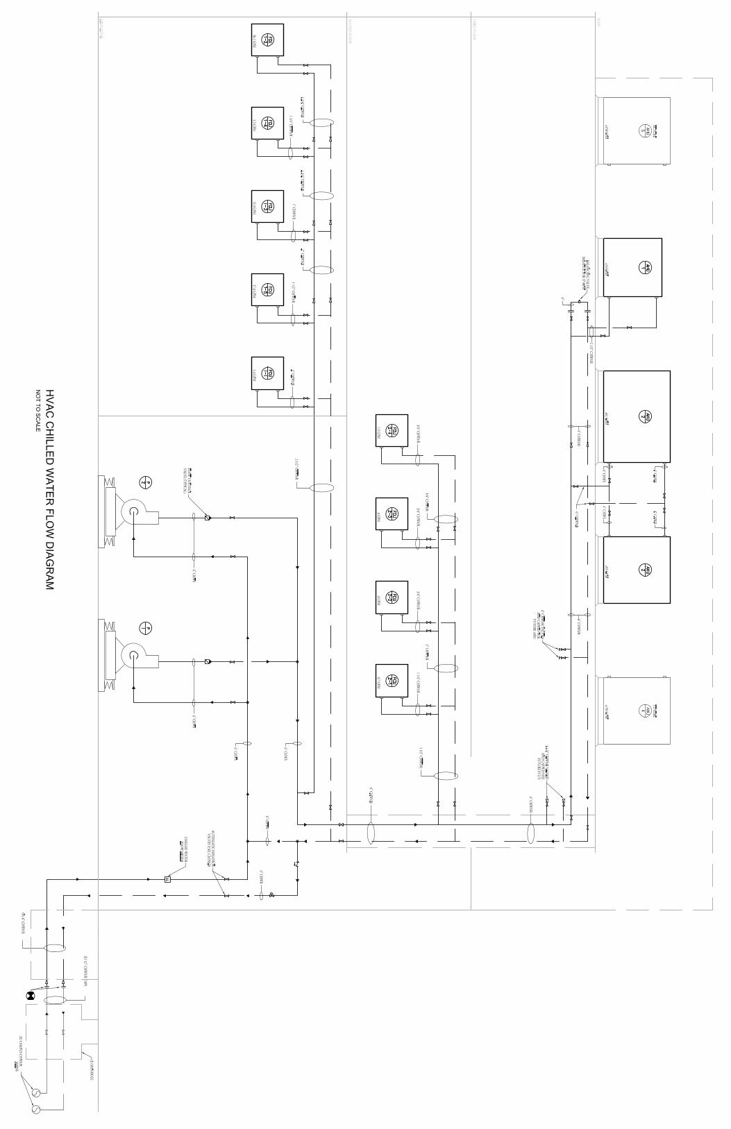
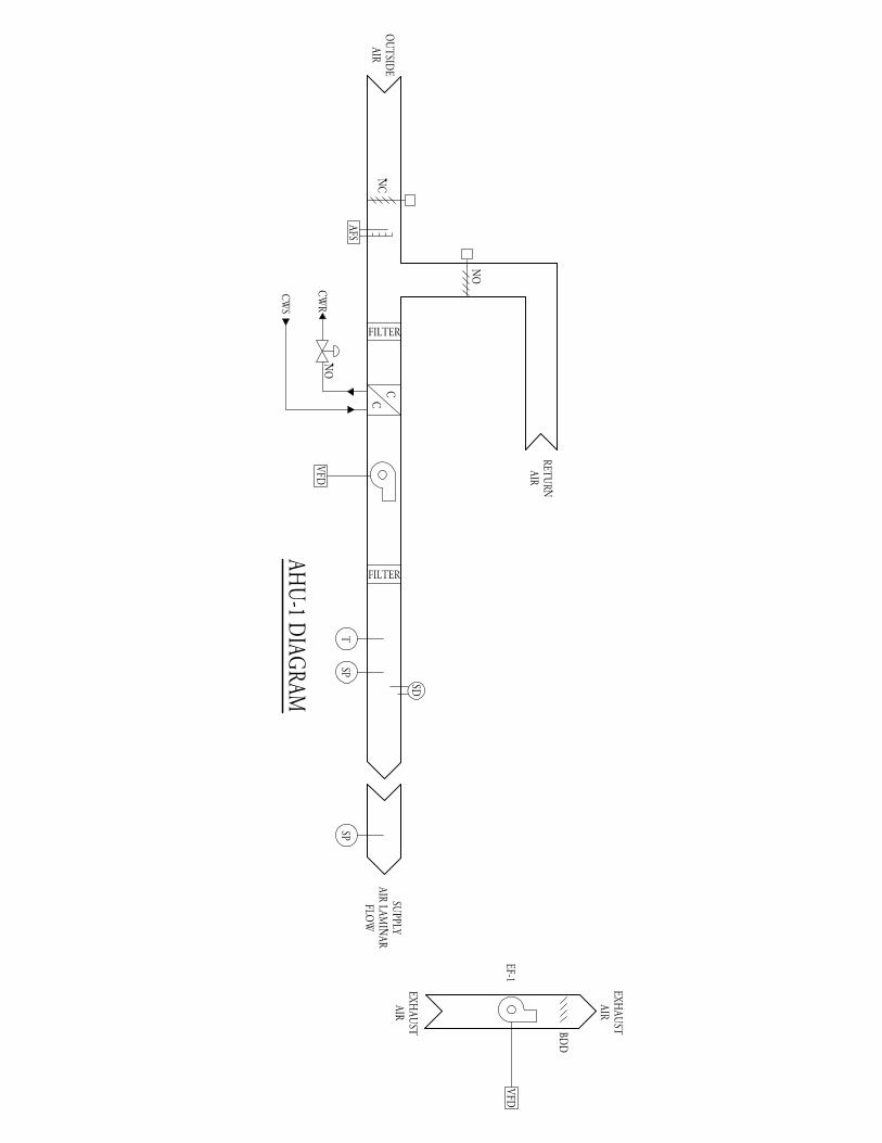
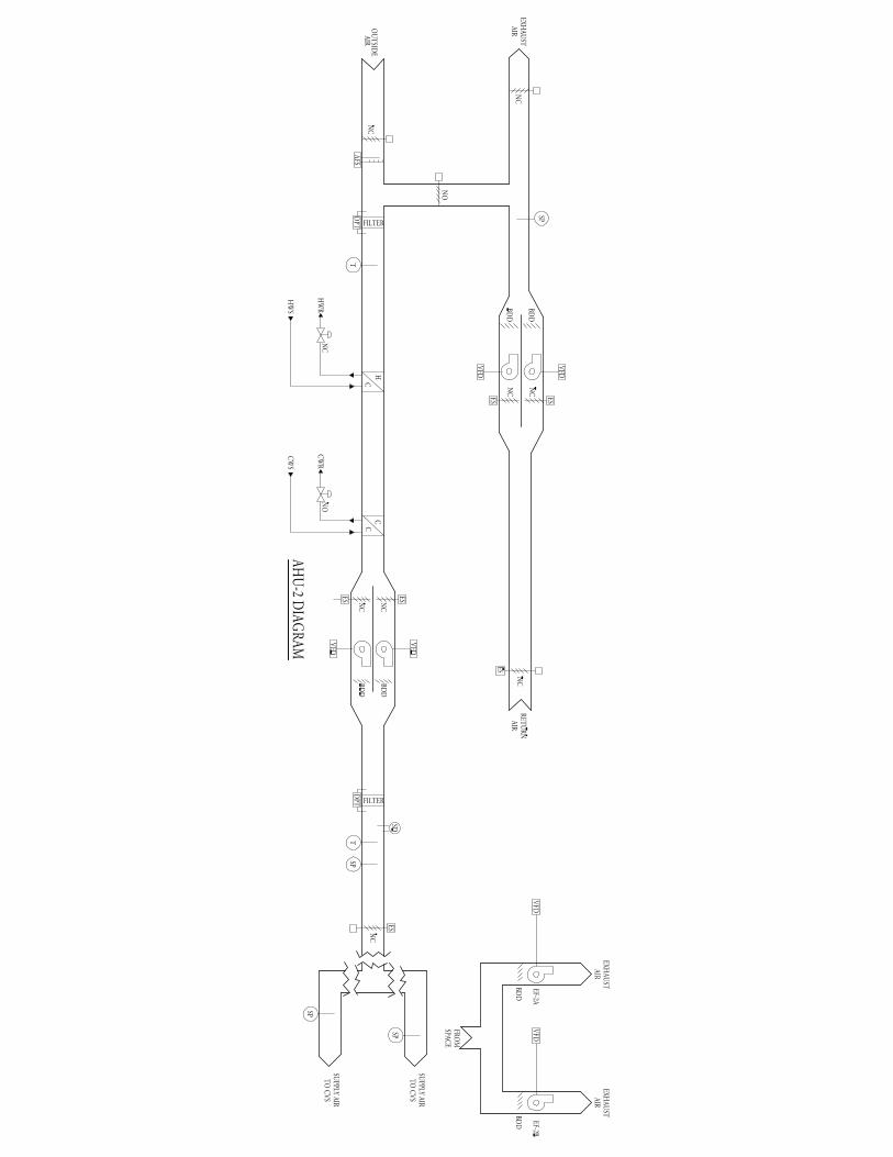
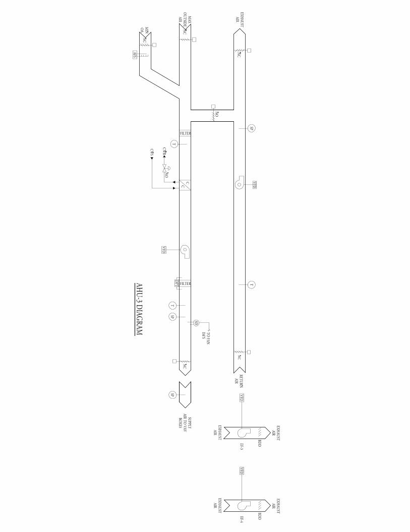
Mechanical Systems Existing Conditions Evaluation 8 of 13,104 gpm and a secondary loop of 12,600 gpm. The points of connection for the Amini Center are a 12” chilled water supply (CHWS) and a 12” chilled water return (CHWR) lines located at the South end of the building. Building Cooling System Like the heating system for the building, the CHWS & CHWR lines enter/leave the facility in the mechanical room on the first floor. According to the designers load calculations, only 6” CHWS & CHWR lines were necessary to serve the Amini Center. The chilled water entering the building is supplied at 42oF. Two pumps located in the first floor mechanical room provide circulation of the chilled water to the AHU and FCU cooling coils throughout the building. Refer to page 2 of Appendix B for the Chilled Water Flow Diagram. Refer to Appendix C for available schedules of the heating equipment. Air Distribution Systems AHU-1 AHU-1 is a 23 Ton constant volume (CV) unit serving the 2,500 ft2 Stem Cell Lab and supporting spaces on the first floor. This AHU is designed to supply 8,200 cfm of air to the space through 2x4 ceiling diffusers with HEPA filters. AHU-1 does not contain a HW heating coil in the unit. All heating for this unit is done through 6 HW duct mounted reheat coils. These reheat coils provide temperature control and zoning for the CV unit. AHU-2 AHU-2 is a 38 Ton variable air volume (VAV) unit serving the 1,700 ft2 Cryogen Freezer room and the 5,300 ft2 Blood Processing Area on the first floor. This AHU is designed to supply 14,800 cfm through a mixture of CV and VAV terminals. The unit is designed with a pre-heat/main heating HW coil in the unit. Zoning is dictated by the terminal units which also have HW reheat coils. VAV terminal units have a minimum flow of 30% design air. AHU-3 AHU-3 is a 63 Ton VAV unit serving 7,200 ft2 of office and misc. space on the 1st floor and 16,700 ft2 of patient bays, offices, and other misc. spaces on the 2nd floor. This AHU is designed to supply 26,900 cfm through VAV terminals with reheat. The unit is not designed with a heating coil in the unit. The VAV terminal units have a minimum flow of 30% design air and provide the only heating through HW reheat coils. FCUs All of the FCUs throughout this facility are horizontal units mounted in the ceiling plenums. These units serve areas with special cooling requirements, like 24/7 cooling for IT rooms. All FCUs have a chilled water coil but no heating coils, therefore these units are used for cooling only. Because these units serve interior spaces and are provided no OA, with the exception of 1 FCU, the heat loss should not be too significant to warrant heating coils. Without any design information for these special areas the loads will have to be assumed to meet what is shown on the schedule. The one FCU that does get OA, FCU-5-1, receives it to maintain the pressure relationship in the Mechanical Pump room.
________________________________________________________________________City of Hope: Amini Medical Center Duarte, California
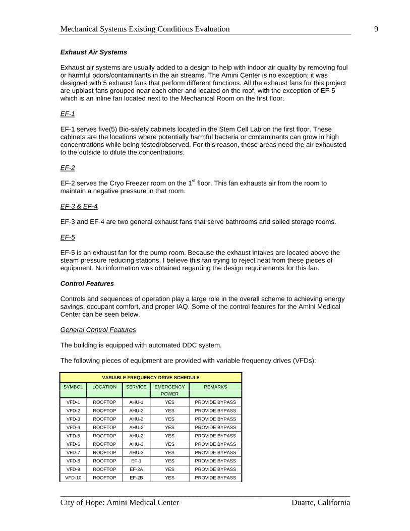
Mechanical Systems Existing Conditions Evaluation 9 Exhaust Air Systems Exhaust air systems are usually added to a design to help with indoor air quality by removing foul or harmful odors/contaminants in the air streams. The Amini Center is no exception; it was designed with 5 exhaust fans that perform different functions. All the exhaust fans for this project are upblast fans grouped near each other and located on the roof, with the exception of EF-5 which is an inline fan located next to the Mechanical Room on the first floor. EF-1 EF-1 serves five(5) Bio-safety cabinets located in the Stem Cell Lab on the first floor. These cabinets are the locations where potentially harmful bacteria or contaminants can grow in high concentrations while being tested/observed. For this reason, these areas need the air exhausted to the outside to dilute the concentrations. EF-2 EF-2 serves the Cryo Freezer room on the 1st floor. This fan exhausts air from the room to maintain a negative pressure in that room. EF-3 & EF-4 EF-3 and EF-4 are two general exhaust fans that serve bathrooms and soiled storage rooms. EF-5 EF-5 is an exhaust fan for the pump room. Because the exhaust intakes are located above the steam pressure reducing stations, I believe this fan trying to reject heat from these pieces of equipment. No information was obtained regarding the design requirements for this fan. Control Features Controls and sequences of operation play a large role in the overall scheme to achieving energy savings, occupant comfort, and proper IAQ. Some of the control features for the Amini Medical Center can be seen below. General Control Features The building is equipped with automated DDC system. The following pieces of equipment are provided with variable frequency drives (VFDs):
VARIABLE FREQUENCY DRIVE SCHEDULE
SYMBOL LOCATION SERVICE EMERGENCY REMARKS POWER
VFD-1 ROOFTOP AHU-1 YES PROVIDE BYPASS
VFD-2 ROOFTOP AHU-2 YES PROVIDE BYPASS
VFD-3 ROOFTOP AHU-2 YES PROVIDE BYPASS
VFD-4 ROOFTOP AHU-2 YES PROVIDE BYPASS
VFD-5 ROOFTOP AHU-2 YES PROVIDE BYPASS
VFD-6 ROOFTOP AHU-3 YES PROVIDE BYPASS
VFD-7 ROOFTOP AHU-3 YES PROVIDE BYPASS
VFD-8 ROOFTOP EF-1 YES PROVIDE BYPASS
VFD-9 ROOFTOP EF-2A YES PROVIDE BYPASS
VFD-10 ROOFTOP EF-2B YES PROVIDE BYPASS
________________________________________________________________________City of Hope: Amini Medical Center Duarte, California
Mechanical Systems Existing Conditions Evaluation 10
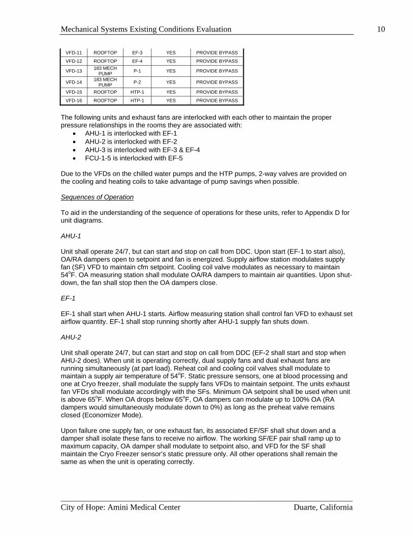
VFD-11 ROOFTOP EF-3 YES PROVIDE BYPASS
VFD-12 ROOFTOP EF-4 YES PROVIDE BYPASS
VFD-13 183 MECH PUMP P-1 YES PROVIDE BYPASS
VFD-14 183 MECH PUMP P-2 YES PROVIDE BYPASS
VFD-15 ROOFTOP HTP-1 YES PROVIDE BYPASS
VFD-16 ROOFTOP HTP-1 YES PROVIDE BYPASS
The following units and exhaust fans are interlocked with each other to maintain the proper pressure relationships in the rooms they are associated with:
• AHU-1 is interlocked with EF-1 • AHU-2 is interlocked with EF-2 • AHU-3 is interlocked with EF-3 & EF-4 • FCU-1-5 is interlocked with EF-5
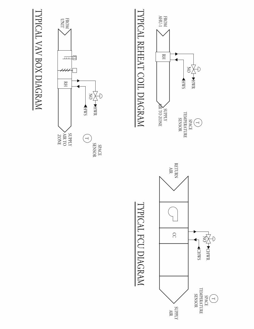
Due to the VFDs on the chilled water pumps and the HTP pumps, 2-way valves are provided on the cooling and heating coils to take advantage of pump savings when possible. Sequences of Operation To aid in the understanding of the sequence of operations for these units, refer to Appendix D for unit diagrams. AHU-1 Unit shall operate 24/7, but can start and stop on call from DDC. Upon start (EF-1 to start also), OA/RA dampers open to setpoint and fan is energized. Supply airflow station modulates supply fan (SF) VFD to maintain cfm setpoint. Cooling coil valve modulates as necessary to maintain 54oF. OA measuring station shall modulate OA/RA dampers to maintain air quantities. Upon shut-down, the fan shall stop then the OA dampers close. EF-1 EF-1 shall start when AHU-1 starts. Airflow measuring station shall control fan VFD to exhaust set airflow quantity. EF-1 shall stop running shortly after AHU-1 supply fan shuts down. AHU-2 Unit shall operate 24/7, but can start and stop on call from DDC (EF-2 shall start and stop when AHU-2 does). When unit is operating correctly, dual supply fans and dual exhaust fans are running simultaneously (at part load). Reheat coil and cooling coil valves shall modulate to maintain a supply air temperature of 54oF. Static pressure sensors, one at blood processing and one at Cryo freezer, shall modulate the supply fans VFDs to maintain setpoint. The units exhaust fan VFDs shall modulate accordingly with the SFs. Minimum OA setpoint shall be used when unit is above 65oF. When OA drops below 65oF, OA dampers can modulate up to 100% OA (RA dampers would simultaneously modulate down to 0%) as long as the preheat valve remains closed (Economizer Mode). Upon failure one supply fan, or one exhaust fan, its associated EF/SF shall shut down and a damper shall isolate these fans to receive no airflow. The working SF/EF pair shall ramp up to maximum capacity, OA damper shall modulate to setpoint also, and VFD for the SF shall maintain the Cryo Freezer sensor’s static pressure only. All other operations shall remain the same as when the unit is operating correctly.
________________________________________________________________________City of Hope: Amini Medical Center Duarte, California
Mechanical Systems Existing Conditions Evaluation 11 EF-2 EF-2 shall start when AHU-2 starts. EF-2 shall stop running shortly after AHU-2 supply fan shuts down. EF-2 contains (2) fans, if one does not start or fails, the other shall energize. AHU-3 Unit shall operate by a schedule and is started and stopped through the DDC system. On start-up, OA/RA dampers shall open to fixed position then fan shall start. Upon shut down CHW valves shall close and fan shall run for another 5 mins. After that time, the fan shall shut down and then the OA dampers to close. EF-3 & EF-4 shall operate when AHU-3 is scheduled to operate. For morning warm up the unit shall keep the OA dampers closed when the OA temperature is greater then 55°F. The supply fan (SF) and return fan (RF) shall energize and the cooling coil valve shall modulate to maintain 54°F supply air. If OA temperature is 55°F or less, economizer mode shall be initiated and the mixed air damper and outdoor air dampers shall modulate to maintain a mixed air temperature of 60°F with a low limit OA temperature of 45°F. In occupied mode the minimum OA damper shall open to its setpoint. Above 55°F and below 45°F the other OA damper shall remain closed. Between 45°F-55°F OA temperature, the OA/MA damper shall modulate to maintain 60°F mixed air temperature. Cooling coil valve shall modulate to maintain 54°F supply air. Rooms with CO2 sensors shall first increase the airflow available from the air terminal serving it before an increase in outside air is provided. Outside air damper shall slowly modulate open (decreasing the mixed air) until the required ventilation air quantities are provided. EF-3 & EF-4 EFs 3&4 shall start operate when AHU-3 operates. VFDs shall be used for air balancing. EFs 3&4 shall stop running shortly after AHU-3 supply fan shuts down. Reheat Coils Space thermostat shall modulate reheat coil valve to maintain temperature setpoint. Constant Volume Terminal Units Air velocity sensor shall modulate damper to maintain cfm setpoint. Space thermostat shall modulate reheat coil valve to maintain temperature setpoint. Zone being served shall be provided with occupied and unoccupied schedule. Variable Air Volume Terminal Units Space thermostat shall modulate the VAV damper or reheat coil valve to maintain temperature setpoint. If VAV damper has reached minimum cfm setpoint, reheat valve shall then modulate to maintain temperature setpoint. Zone being served shall be provided with occupied and unoccupied schedule. Air terminals serving rooms with CO2 sensors shall increase air quantity on VAV unit, thermostat to modulate reheat valve, until CO2 reading are acceptable. If continued CO2 concentration, air handling unit shall gradually increase OA until CO2 levels are met.
________________________________________________________________________City of Hope: Amini Medical Center Duarte, California
Mechanical Systems Existing Conditions Evaluation 12 Fan Coil Units (FCU) Space thermostat shall energize supply fan modulate cooling coil valve to maintain temperature setpoint. FCU-1-5 is provided with two thermostats in two separate rooms it serves. The higher recorded temperature is the controlling point for the unit cooling setpoint. EF-5 shall operate when FCU-1-5 operates. EF-5 EF-5 shall start when FCU-1-5 starts. EF-2 shall stop running shortly after FCU-5-1 supply fan shuts down. Steam Pressure Monitoring The DDC controls system shall record the steam flow rate measured by the flow meter. The DDC system shall interface with the mass flow meter for energy monitoring. Heat Transfer Package The DDC shall monitor hot water supply (HWS) and return temperatures. Alarm shall be sent to if HWS falls below 160°F. Chilled Water Plant/Pumps On a call for cooling by any one of the air distribution systems, the chilled water valve shall open and both pumps shall energize. Pump VFDs shall modulate to maintain differential pressure setpoint. Upon failure of one pump, the other shall operate to maintain necessary setpoint. Building CHWS and CHWR temperatures shall be monitored. If the differential temperature is above the setpoint by 15°F, then the chilled water bypass valve shall open. If the differential temperature setpoint is 9°F or less, then the chilled water bypass valve shall close.
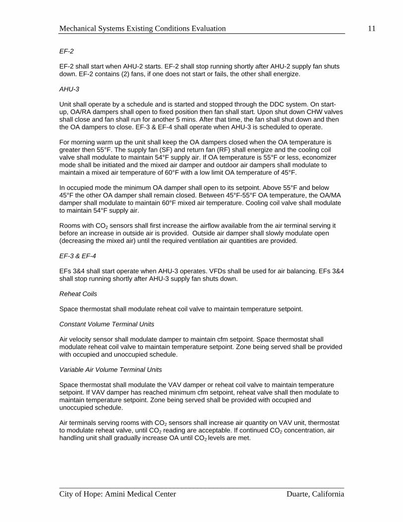
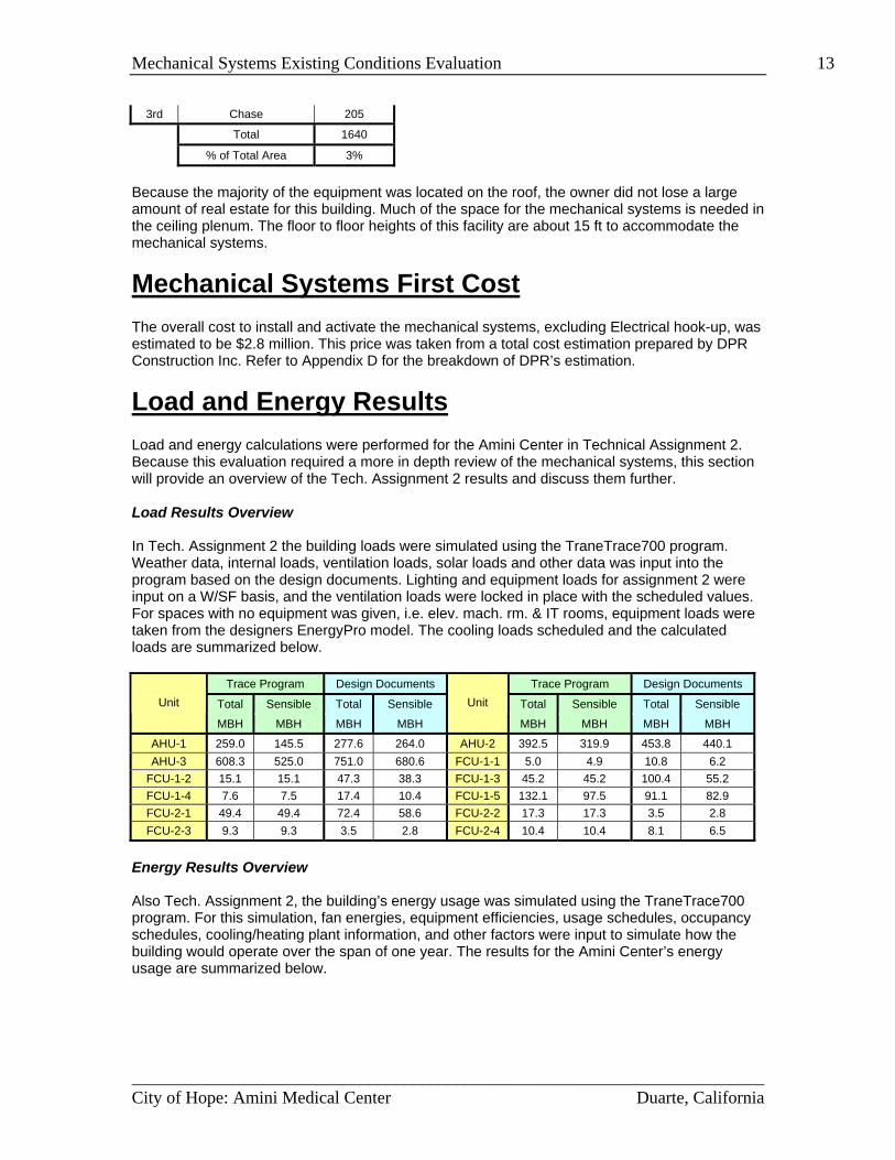
Lost Rentable Space Due to the world growing and expanding, land has become harder to come by, especially in large cities. Building owners therefore want as much rentable/useable space inside their building as possible. Obviously a building cannot operate without mechanical and electrical systems, but these systems take up rentable space. For the Amini Center, the lost rentable space to mechanical and electrical systems can be seen in the following table. These values do not incorporate janitor closets, elevator machine rooms, IT rooms, etc.; just mechanical and electrical spaces & chases.
Amini Center Lost Rentable Space Floor Space Type Area (ft2)
1st Mechanical 500 1st Electrical 600 1st Chase 30 2nd Mechanical 0 2nd Electrical 100 2nd Chase 205 3rd Mechanical 0 3rd Electrical -
________________________________________________________________________City of Hope: Amini Medical Center Duarte, California
Mechanical Systems Existing Conditions Evaluation 13
3rd Chase 205
Total 1640
% of Total Area 3%
Because the majority of the equipment was located on the roof, the owner did not lose a large amount of real estate for this building. Much of the space for the mechanical systems is needed in the ceiling plenum. The floor to floor heights of this facility are about 15 ft to accommodate the mechanical systems.
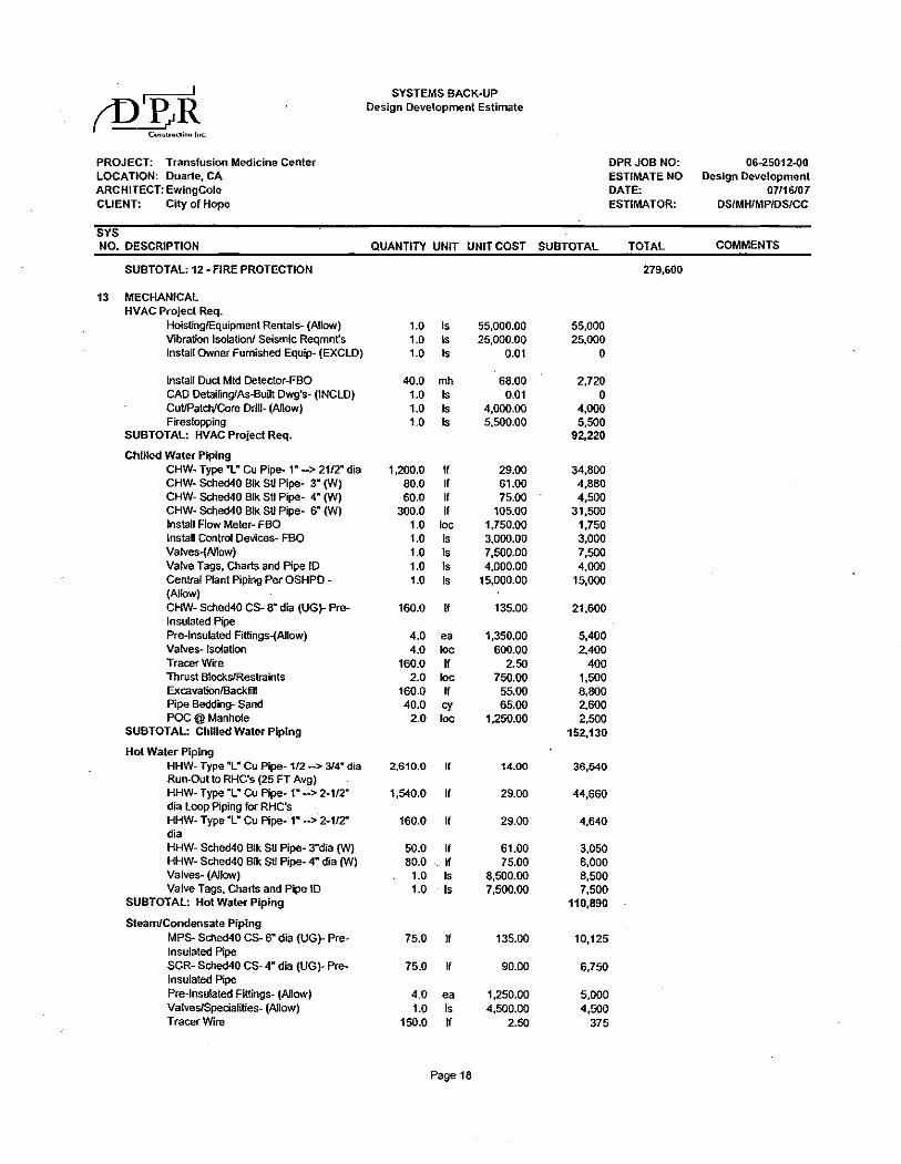
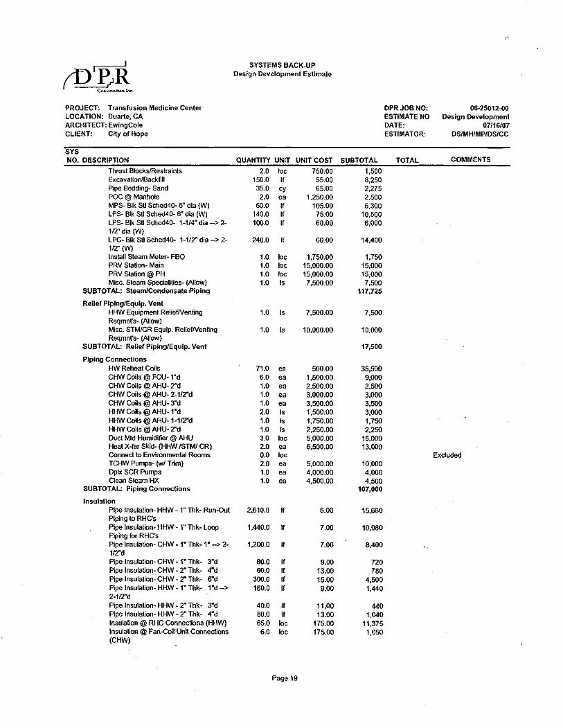
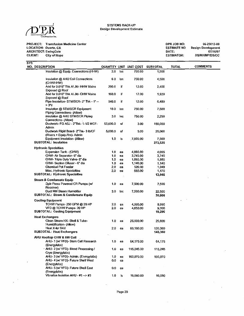
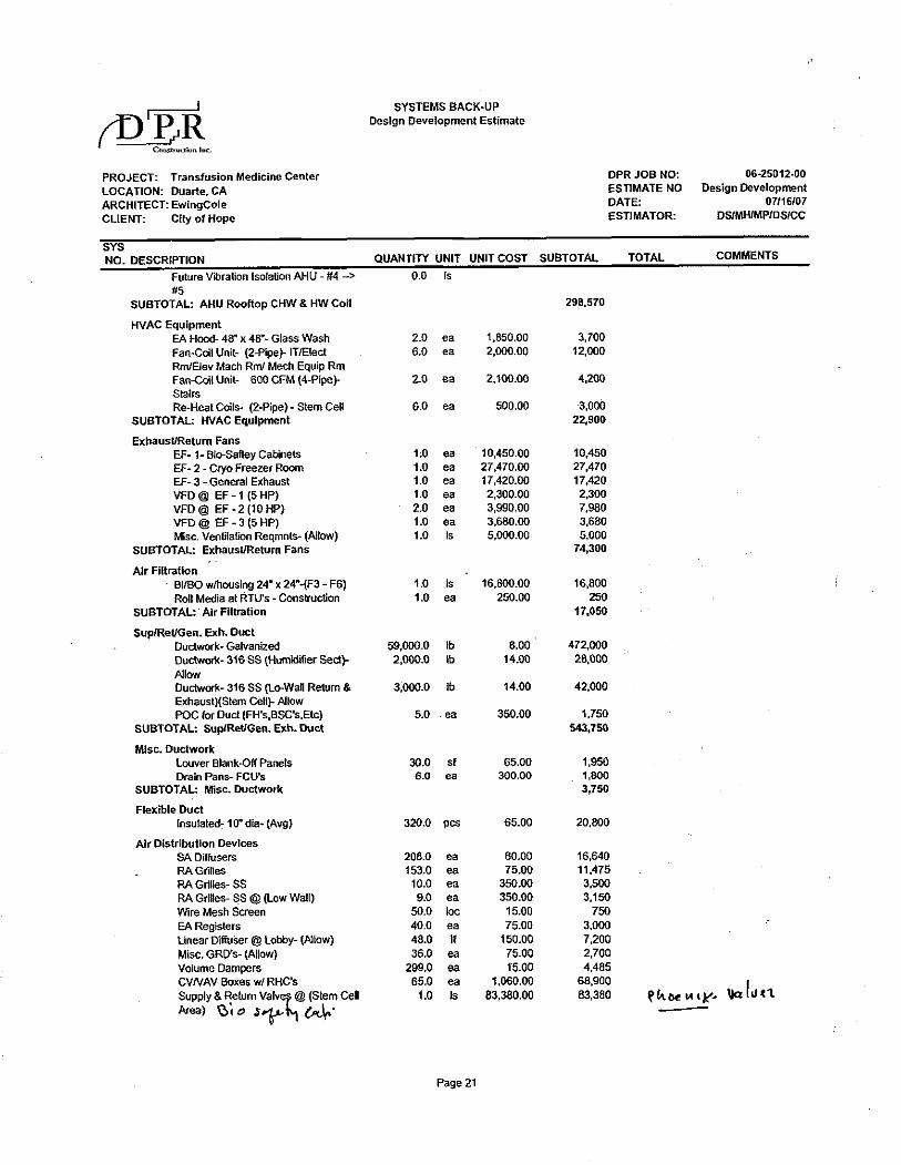
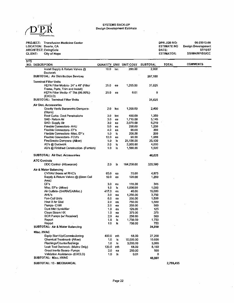
Mechanical Systems First Cost The overall cost to install and activate the mechanical systems, excluding Electrical hook-up, was estimated to be $2.8 million. This price was taken from a total cost estimation prepared by DPR Construction Inc. Refer to Appendix D for the breakdown of DPR’s estimation.
Load and Energy Results Load and energy calculations were performed for the Amini Center in Technical Assignment 2. Because this evaluation required a more in depth review of the mechanical systems, this section will provide an overview of the Tech. Assignment 2 results and discuss them further. Load Results Overview In Tech. Assignment 2 the building loads were simulated using the TraneTrace700 program. Weather data, internal loads, ventilation loads, solar loads and other data was input into the program based on the design documents. Lighting and equipment loads for assignment 2 were input on a W/SF basis, and the ventilation loads were locked in place with the scheduled values. For spaces with no equipment was given, i.e. elev. mach. rm. & IT rooms, equipment loads were taken from the designers EnergyPro model. The cooling loads scheduled and the calculated loads are summarized below.
Trace Program Design Documents Trace Program Design Documents
Total Sensible Total Sensible Total Sensible Total Sensible Unit
MBH MBH MBH MBH
Unit
MBH MBH MBH MBH
AHU-1 259.0 145.5 277.6 264.0 AHU-2 392.5 319.9 453.8 440.1 AHU-3 608.3 525.0 751.0 680.6 FCU-1-1 5.0 4.9 10.8 6.2
FCU-1-2 15.1 15.1 47.3 38.3 FCU-1-3 45.2 45.2 100.4 55.2 FCU-1-4 7.6 7.5 17.4 10.4 FCU-1-5 132.1 97.5 91.1 82.9 FCU-2-1 49.4 49.4 72.4 58.6 FCU-2-2 17.3 17.3 3.5 2.8 FCU-2-3 9.3 9.3 3.5 2.8 FCU-2-4 10.4 10.4 8.1 6.5
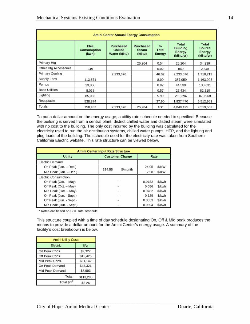
Energy Results Overview Also Tech. Assignment 2, the building’s energy usage was simulated using the TraneTrace700 program. For this simulation, fan energies, equipment efficiencies, usage schedules, occupancy schedules, cooling/heating plant information, and other factors were input to simulate how the building would operate over the span of one year. The results for the Amini Center’s energy usage are summarized below.
________________________________________________________________________City of Hope: Amini Medical Center Duarte, California
Mechanical Systems Existing Conditions Evaluation 14
Amini Center Annual Energy Consumption
Elec
Consumption (kwh)
Purchased Chilled
Water (kBtu)
Purchased Steam (kBtu)
% Total
Energy
Total Building Energy
(kBtu/yr)
Total Source Energy
(kBtu/yr)
Primary Htg 26,204 0.54 26,204 34,939 Other Htg Accessories 249 0.02 849 2,548 Primary Cooling 2,233,676 46.07 2,233,676 1,718,212 Supply Fans 113,671 8.00 387,959 1,163,993 Pumps 13,050 0.92 44,539 133,631 Base Utilities 8,038 0.57 27,434 82,310 Lighting 85,055 5.99 290,294 870,968 Receptacle 538,374 37.90 1,837,470 5,512,961 Totals 758,437 2,233,676 26,204 100 4,848,425 9,519,562
To put a dollar amount on the energy usage, a utility rate schedule needed to specified. Because the building is served from a central plant, district chilled water and district steam were simulated with no cost to the building. The only cost incurred by the building was calculated for the electricity used to run the air distribution systems, chilled water pumps, HTP, and the lighting and plug loads of the building. The schedule used for the electricity rate was taken from Southern California Electric website. This rate structure can be viewed below.
Amini Center Input Rate Structure Utility Customer Charge Rate
Electric Demand On Peak (Jan. – Dec.) 24.95 $/KW Mid Peak (Jan. – Dec.)
334.55 $/month 2.58 $/KW
Electric Consumption On Peak (Oct. – May) - 0.0782 $/kwh Off Peak (Oct. – May) - 0.056 $/kwh Mid Peak (Oct. – May) - 0.0782 $/kwh On Peak (Jun. - Sept.) - 0.129 $/kwh Off Peak (Jun. - Sept.) - 0.0553 $/kwh Mid Peak (Jun. - Sept.) - 0.0694 $/kwh
* Rates are based on SCE rate schedule This structure coupled with a time of day schedule designating On, Off & Mid peak produces the means to provide a dollar amount for the Amini Center’s energy usage. A summary of the facility’s cost breakdown is below.
Amini Utility Costs
Electric $/yr
On Peak Cons. $9,327 Off Peak Cons. $15,425 Mid Peak Cons. $31,142 On Peak Demand $48,321 Mid Peak Demand $8,993
Total: $113,208 Total $/ft2 $3.26
________________________________________________________________________City of Hope: Amini Medical Center Duarte, California
Mechanical Systems Existing Conditions Evaluation 15 Discussion Because construction of this building is scheduled to be complete in February, 2009, no information concerning energy usage and billing exist. The following discussion will therefore not evaluate any billing differences but discuss aspects of the model and its believed accuracy. Loads Loads for any building are subject to estimation and interpolation and the Amini Center is no different. I believe the solar loads and the wall loads calculated by the program are great estimations for the building’s performance; as long as the envelope was input correctly. For the internal loads, however, a designer makes estimations for the heat produced in the space based on equipment, people activity, ventilation requirements, and other factors. Many pieces of equipment can be referenced for heat loads, but not all equipment is listed. In the case for this complex, many areas like the labs and research areas contain pieces of equipment which can not be looked up, making it hard to estimate the heat loads without going to the manufacturers. I believe this is the main discrepancy for the differences in loads observed by Tech. Assignment 2 and those scheduled. Another discrepancy that factors into the load differences was the fact that the owner wanted there to by 15% extra capacity on all the AHUs. Some minor factors I believe to affect the loads include slight differences in weather data, people loads, and lighting loads. These factors will also change the load calculations, but no where near the extent of the previously mentioned factors. The loads for the FCUs seem to be marginally different from scheduled loads. Considering these W/SF loads were taken from the designer’s energy model, I initially thought they were accurate. After further investigation I feel the loads were input wrong or changed by the design team, creating inaccurate loads from what is scheduled. Energy The energy results from Tech. Assignment 2 were hard for me to judge because I’m not aware of typical energy costs for a clinical building in the LA area. After a more in depth review of the Amini Center’s mechanical systems, I do believe the numbers calculated in Assignment 2 are low compared to what the building will actually see. I feel the building was not correctly modeled with the proper control schemes and loads. In Assignment 2, the AHUs and EFs were input based on building occupancy schedule, not based on loads. Considering both AHU-1 and AHU-2 are operating 24/7, the energy usage will be greatly different. Other factors that were not incorporated into the model include the rooms with CO2 sensors and the demand limiting ventilation applied to AHU-3. Other design conditions that might affect the cost include design conditions like oversized units, ventilation requirements, and also the facility’s need for positively and negatively pressured rooms. The last energy issue with the Amini Center is the fact that the numbers given in this evaluation apply only to the first and second floor units. The third floor, future units, were not accounted for.
System Critique Because the Amini Medical Center is an addition to an already existing campus, it appeared to be a simple choice for the engineer on how the building would be heated and cooled. Having existing chilled water and steam lines gave the designer excellent resources to design an efficient building.
________________________________________________________________________City of Hope: Amini Medical Center Duarte, California
Mechanical Systems Existing Conditions Evaluation 16 Central Plant Because there is little known about the central heating plant, there is no room to discuss its design. For a campus facility like this one, I do believe a high pressure steam system provides benefits for the buildings on campus. The central water cooled chiller plant is also believed to have benefits for a campus community. Not knowing how the chillers are piped (series or parallel) and the control sequencing for them does not allow any critique based on energy consumption. Building Equipment For this facility, having the water cooled AHUs on the roof, took up minimal floor area for the tenant. It did however increase the plenum size to allow the necessary duct runs and equipment, there by increasing the overall height of the building. The specific requirements for the spaces seem to be met very well with the system that has been provided. The temperature control seems to be accounted for with reheat coils on the CV system and the terminal units on the VAV systems. All two way valves were used to gain energy savings on the pumps with VFDs. One issue I had with the system resulted from the controls of AHU-1. The VFDs on AHU-1 and EF-1 seemed unnecessary to me because it is a constant volume system. I don’t know why these features were added, but it might be a design requirement for the lab it serves. Another interesting design feature was the dual fan system for AHU-2. This feature was obviously added to provide the Cryo freezer with redundancy, but it seemed out of the ordinary. It had me curious if there was another way to provide redundancy for that space; most likely not without increasing first cost significantly. Overall I believe the system is a very good design which seems to meet the requirements of the owner and also provides energy efficient strategies.
________________________________________________________________________City of Hope: Amini Medical Center Duarte, California
Mechanical Systems Existing Conditions Evaluation 17
________________________________________________________________________City of Hope: Amini Medical Center Duarte, California
References ASHRAE. 2007, ANSI/ASHRAE, Standard 62.1-2007, Ventilation for Acceptable Indoor Air Quality. American Society of Heating, Refrigeration and Air Conditioning Engineers, Inc., Atlanta, GA. ASHRAE. 2007, ANSI/ASHRAE, Standard 90.1-2007, Energy Standard for Building Except Low Rise Residential Buildings. American Society of Heating, Refrigeration and Air Conditioning Engineers, Inc., Atlanta, GA. ASHRAE. 2005, 2005 ASHRAE Handbook – Fundamentals. American Society of Heating Refrigeration and Air Conditioning Engineers, Inc., Atlanta, GA. 2001. EwingCole. 2007. City of Hope: Amini Medical Center Construction Documents and Specifications. EwingCole, Irvine, CA DPR Construction Inc. 2007. City of Hope: Transfusion Medical Center Design Development Estimate. DPR Construction Inc., Newport Beach, CA
Mechanical Systems Existing Conditions Evaluation
Appendix A
Vicinity Map & Air Distribution Maps
________________________________________________________________________City of Hope: Amini Medical Center Duarte, California
Mechanical Systems Existing Conditions Evaluation
Appendix B
Flow Diagrams
________________________________________________________________________City of Hope: Amini Medical Center Duarte, California
Mechanical Systems Existing Conditions Evaluation
Appendix C
Equipment Schedules
________________________________________________________________________City of Hope: Amini Medical Center Duarte, California
Flow (GPM) EWT (°F) LWT (°F) Flow (GPM) EWT (°F) LWT (°F)CH-1 York 2S2J4-DEBO 1750 3111 54 40.5 5250 83.5 92.85CH-2 York 2S2J4-DEBO 1750 3111 54 40.5 5250 83.5 92.85CH-3 York 2S2J4-DEBO 1750 3111 54 40.5 5250 83.5 92.85
Summation 5250 9333
Centrifugal Water Chiller Schedule
Tag Manufacturer Model No. Nominal Capacity (Tons)
Evaporative Side Condenser Side
MBH EWT (°F) LWT (°F) GPM EWT (°F) LWT (°F) GPM LB/HrABCH-1 Broad B56000 1900 23800 56 44 4553 85 95 8005 16967
Steam Absporption Chiller Schedule
Tag Model No. Nominal Capacity (Tons)
Evaporative Side Condenser Side
MIN
SYMBOL TYPE SERVICE LOCATION DESIGN RATED OA WEIGHT MOTOR MOTOR MAX. FACE APD/ MIN. MAX EAT LAT FACE VEL. APD/ WATER SIZE EFF. REMARKS
(SEE NOTE 1) CFM CFM CFM (LB.) EXT. TOT. TYPE HP CFM EXT. TOT. TYPE HP DB WB DB WB TOT. SENS. VEL./ FPM IN. WG GPM PD/FT. WG ROWS FINS/IN. LOC %%DF %%DF MBH FPM IN. WG GPM LOC INIT. FINAL WxHxD/ IN. % TYPE L W H (SEE NOTES 11 & 12)
PF 0.25 0.5 30 FLAT
AHU-1 CV STEM CELL RESEARCH ROOF 8,200 8,700 2,800 6,648 4 PLENUM 15 - - - - - 79.9 62.7 52.5 52 262.8 257.5 500 34 10 - - - - - - - 284 64 67.5 OUTDOOR ROOFTOP UNIT
FF 0.5 1 95 CART
7,100 10,000 6700 PF 0.25 0.5 30 FLAT
AHU-2 VAV BLOOD PROCESSING/CRYO ROOF 7,500 16,645 2.25 PLENUM 2 @ 30 1.25 PLENUM 2 @ 7.5 85.5 64.3 52.5 52 731.6 712.8 500 98 10 44 55 172.8 600 17.3 375 112 91.5 DUAL FAN OUTDOOR ROOFTOP UNIT (NOTE 13)
7100 10000 6700 FF 0.5 1 95 CART
PF 0.25 0.5 30 FLAT
AHU-3 VAV ADMINISTRATIVE AREAS ROOF 26,300 26,300 6,700 16,050 2.25 PLENUM 50 19600 1.25 PLENUM 15 78.7 62.6 54.1 52.6 787.7 698.8 500 105 10 - - - - - - - 321 98 118 OUTDOOR ROOFTOP UNIT
FF 0.5 1 95 CART
NOTES:
1. VAV = VARIABLE AIR VOLUME (W/ VFD ON SUPPLY FAN & ON RETURN FAN) CV - CONSTANT VOLUME
2. TOTAL SP IS AN ESTIMATED VALUE BASED ON INFORMATION OF ONE MANUFACTURER OF AHU's. ADJUST TOTAL
AS REQUIRED BASED ON ACTUAL UNIT AND COIL LOSSES AND SPECIFIED EXTERNAL AND FILTER FINAL SP.
3. TYPE - BI= BACKWARD INCLINED, AF = AIR FOIL, FC = FORWARD CURVED
4. ENTERING CHILLED WATER TEMPERATURE OF 42%%DF.
5. LOC - P=PREHEAT LOCATION H=HEATING OR REHEAT LOCATION
6. PRIMARY HEATING WATER EWT = 160%%DF & LWT = 140%%DF.
7. NOT USED
8. ALL PREHEAT COILS SHALL BE PARALLEL FLOW TYPE SIZED FOR MINIMUM TUBE VELOCITY OF 3 FT/S.
9. LOC - PF=PREFILTER LOCATION AF=AFTERFILTER LOCATION
10. SEE DIAGRAM BELOW FOR ADDITIONAL ACCESSORY AND ARRANGEMENT INFORMATION
11. SEE ACOUSTICAL PERFORMANCE SCHEDULE.
12. FANS ARE TO BE INTERNALLY ISOLATED WITH SPRING ISOLATORS (2" DEFLECTION)
13. BOTH SUPPLY FANS TO BE SIZED FOR 10,000 CFM, UNDER NORMAL OPERATING CONDITIONS, BOTH FANS WILL OPERATE AT 7,100 CFM. PHC CONDITIONS BASED ON 10,000 CFM
14.
15.
MAX. AHU SIZE
(INCHES)
AIR HANDLERS SHALL BE SET ON ROOF CURBS; EXCEPT AHU-3 WHICH IS SECURED TO AN EQUIPMENT PAD.
ROOF CURBS SHALL PROVIDE A LEVEL SURFACE FOR AIR HANDLERS. COORDINATE ROOF CURB REQUIREMENTS WITH ROOF SLOPE AND STRUCTURE.
COOLING COIL
WATER (SEE NOTE 4)
PREHEAT/HEATING COIL (SEE NOTES 5, 6, 7, 8)
AIR HANDLING UNIT SCHEDULE
SUPPLY FAN DATA (SEE NOTES 2 & 3)
SP/IN.WG.
RETURN FAN DATA (SEE NOTES 2 & 3)
SP/IN.WG. EAT %%DF LAT %%DF MBH
FILTERS (SEE NOTE 9)
APD/IN WG
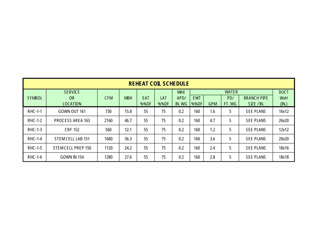
SERVICE MAX DUCTSYMBOL OR CFM MBH EAT LAT APD/ EWT PD/ BRANCH PIPE WxH
LOCATION %%DF %%DF IN. WG %%DF GPM FT. WG SIZE / IN. (IN.)RHC-1-1 GOWN OUT 161 730 15.8 55 75 0.2 160 1.6 5 SEE PLANS 16x12
RHC-1-2 PROCESS AREA 163 2160 46.7 55 75 0.2 160 4.7 5 SEE PLANS 26x20
RHC-1-3 CRF 152 560 12.1 55 75 0.2 160 1.2 5 SEE PLANS 12x12
RHC-1-4 STEM CELL LAB 151 1680 36.3 55 75 0.2 160 3.6 5 SEE PLANS 20x20
RHC-1-5 STEM CELL PREP 150 1120 24.2 55 75 0.2 160 2.4 5 SEE PLANS 18x16
RHC-1-6 GOWN IN 154 1280 27.6 55 75 0.2 160 2.8 5 SEE PLANS 18x18
REHEAT COIL SCHEDULEWATER
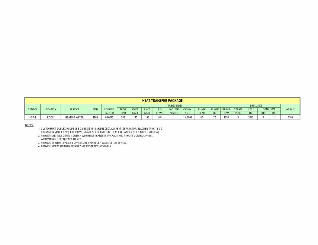
SYMBOL LOCATION SERVICE MBH FOULING FLOW EWT LWT PD/ NO. OF CONN. PUMP PUMP PUMP STEAM LBS/ WEIGHT
FACTOR GPM %%DF %%DF FT.WG. PASSES SIZE HEAD HP RPM PSIG HR SUP. RET.HTP-1 ROOF HEATING WATER 1964 0.00045 200 140 160 0.8 1/4/1900 80 7.5 1750 5 2045 4 1 5100
NOTES:1. CUSTOM UNIT DUPLEX PUMPS (B & G SERIES 1510 MODEL 2BC), AIR VENT, SEPARATOR, BLADDER TANK, (B & G
EXPANSION MODEL B200), FILL VALVE, SINGLE SHELL AND TUBE HEAT EXCHANGER (B & G MODEL SU-103-2).2. PROVIDE UNIT DISCONNECT SWITCH WITH HEAT TRANSFER PACKAGE AND REMOTE CONTROL PANEL
WITH VARIABLE FREQUENCY DRIVES.3. PROVIDE ET WITH 12 PSIG FILL PRESSURE AND RELIEF VALVE SET AT 50 PSIG.4. PROVIDE VIBRATION ISOLATION/SEISMIC RESTRAINT ASSEMBLY.
TUBE SIDE SHELL SIDECONN. SIZE
HEAT TRANSFER PACKAGE
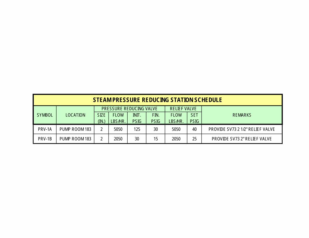
SYMBOL LOCATION SIZE FLOW INIT. FIN. FLOW SET REMARKS
(IN.) LBS/HR. PSIG PSIG LBS/HR. PSIGPRV-1A PUMP ROOM 183 2 5050 125 30 5050 40 PROVIDE SV73 2 1/2" RELIEF VALVE
PRV-1B PUMP ROOM 183 2 2050 30 15 2050 25 PROVIDE SV73 2" RELIEF VALVE
STEAM PRESSURE REDUCING STATION SCHEDULEPRESSURE REDUCING VALVE RELIEF VALVE
INLET WOSYMBOL TYPE SERVICE SIZE SP HTG EAT LAT WATER (NOTE 3)
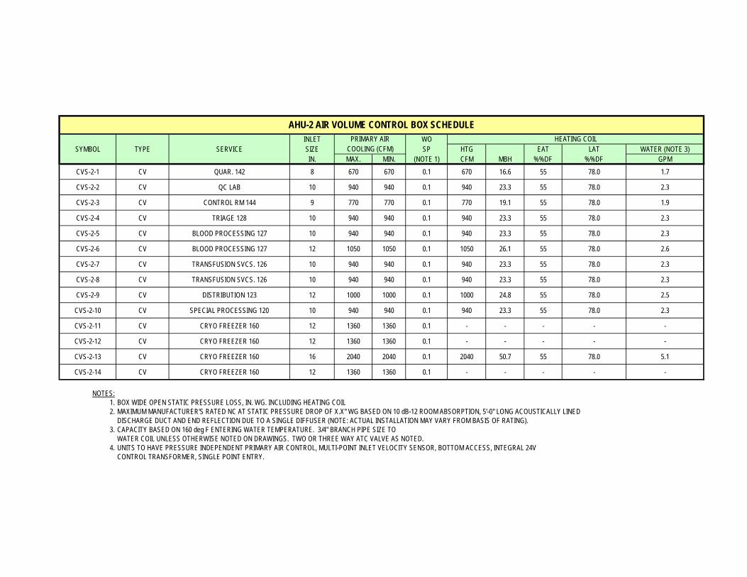
IN. MAX. MIN. (NOTE 1) CFM MBH %%DF %%DF GPMCVS-2-1 CV QUAR. 142 8 670 670 0.1 670 16.6 55 78.0 1.7
CVS-2-2 CV QC LAB 10 940 940 0.1 940 23.3 55 78.0 2.3
CVS-2-3 CV CONTROL RM 144 9 770 770 0.1 770 19.1 55 78.0 1.9
CVS-2-4 CV TRIAGE 128 10 940 940 0.1 940 23.3 55 78.0 2.3
CVS-2-5 CV BLOOD PROCESSING 127 10 940 940 0.1 940 23.3 55 78.0 2.3
CVS-2-6 CV BLOOD PROCESSING 127 12 1050 1050 0.1 1050 26.1 55 78.0 2.6
CVS-2-7 CV TRANSFUSION SVCS. 126 10 940 940 0.1 940 23.3 55 78.0 2.3
CVS-2-8 CV TRANSFUSION SVCS. 126 10 940 940 0.1 940 23.3 55 78.0 2.3
CVS-2-9 CV DISTRIBUTION 123 12 1000 1000 0.1 1000 24.8 55 78.0 2.5
CVS-2-10 CV SPECIAL PROCESSING 120 10 940 940 0.1 940 23.3 55 78.0 2.3
CVS-2-11 CV CRYO FREEZER 160 12 1360 1360 0.1 - - - - -
CVS-2-12 CV CRYO FREEZER 160 12 1360 1360 0.1 - - - - -
CVS-2-13 CV CRYO FREEZER 160 16 2040 2040 0.1 2040 50.7 55 78.0 5.1
CVS-2-14 CV CRYO FREEZER 160 12 1360 1360 0.1 - - - - -
NOTES:1. BOX WIDE OPEN STATIC PRESSURE LOSS, IN. WG. INCLUDING HEATING COIL2. MAXIMUM MANUFACTURER'S RATED NC AT STATIC PRESSURE DROP OF X.X" WG BASED ON 10 dB-12 ROOM ABSORPTION, 5'-0" LONG ACOUSTICALLY LINED
DISCHARGE DUCT AND END REFLECTION DUE TO A SINGLE DIFFUSER (NOTE: ACTUAL INSTALLATION MAY VARY FROM BASIS OF RATING).3. CAPACITY BASED ON 160 deg F ENTERING WATER TEMPERATURE. 3/4" BRANCH PIPE SIZE TO
WATER COIL UNLESS OTHERWISE NOTED ON DRAWINGS. TWO OR THREE WAY ATC VALVE AS NOTED.4. UNITS TO HAVE PRESSURE INDEPENDENT PRIMARY AIR CONTROL, MULTI-POINT INLET VELOCITY SENSOR, BOTTOM ACCESS, INTEGRAL 24V
CONTROL TRANSFORMER, SINGLE POINT ENTRY.
AHU-2 AIR VOLUME CONTROL BOX SCHEDULEPRIMARY AIR
COOLING (CFM)HEATING COIL
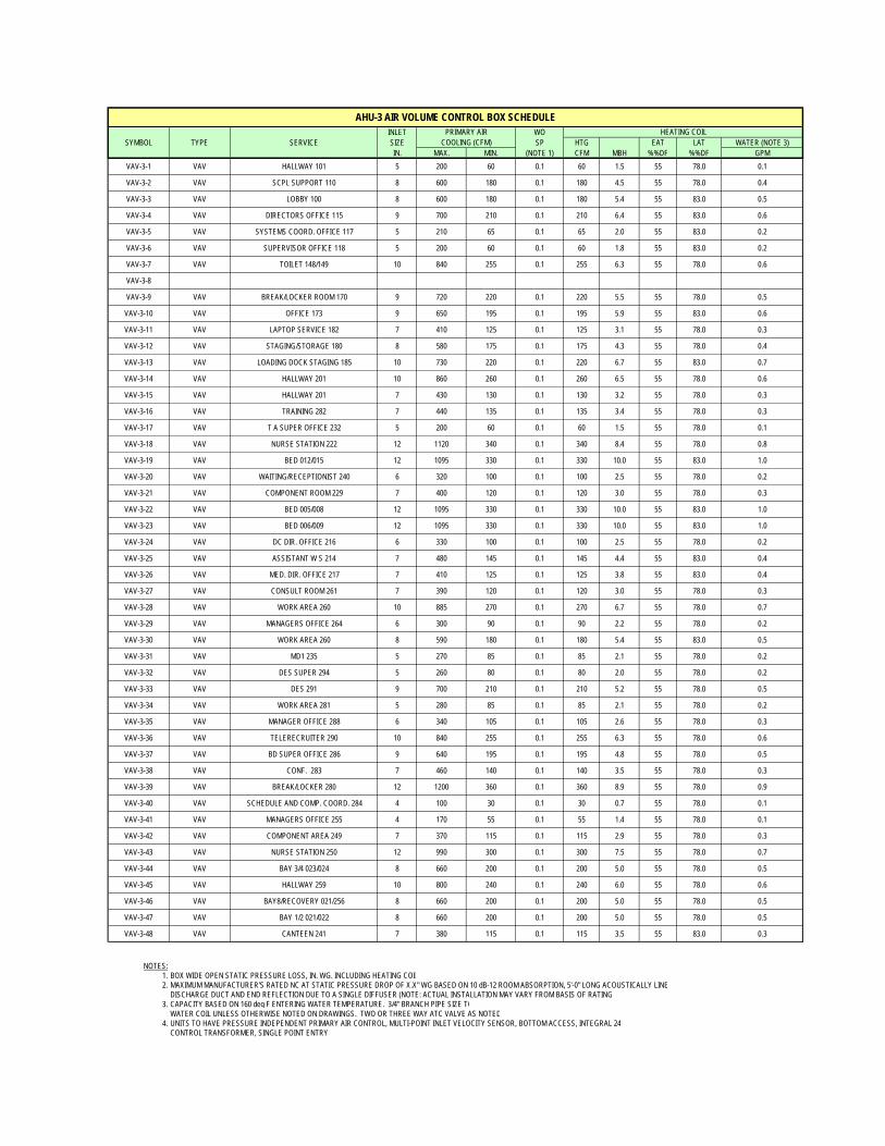
INLET WOSYMBOL TYPE SERVICE SIZE SP HTG EAT LAT WATER (NOTE 3)
IN. MAX. MIN. (NOTE 1) CFM MBH %%DF %%DF GPMVAV-3-1 VAV HALLWAY 101 5 200 60 0.1 60 1.5 55 78.0 0.1
VAV-3-2 VAV SCPL SUPPORT 110 8 600 180 0.1 180 4.5 55 78.0 0.4
VAV-3-3 VAV LOBBY 100 8 600 180 0.1 180 5.4 55 83.0 0.5
VAV-3-4 VAV DIRECTORS OFFICE 115 9 700 210 0.1 210 6.4 55 83.0 0.6
VAV-3-5 VAV SYSTEMS COORD. OFFICE 117 5 210 65 0.1 65 2.0 55 83.0 0.2
VAV-3-6 VAV SUPERVISOR OFFICE 118 5 200 60 0.1 60 1.8 55 83.0 0.2
VAV-3-7 VAV TOILET 148/149 10 840 255 0.1 255 6.3 55 78.0 0.6
VAV-3-8
VAV-3-9 VAV BREAK/LOCKER ROOM 170 9 720 220 0.1 220 5.5 55 78.0 0.5
VAV-3-10 VAV OFFICE 173 9 650 195 0.1 195 5.9 55 83.0 0.6
VAV-3-11 VAV LAPTOP SERVICE 182 7 410 125 0.1 125 3.1 55 78.0 0.3
VAV-3-12 VAV STAGING/STORAGE 180 8 580 175 0.1 175 4.3 55 78.0 0.4
VAV-3-13 VAV LOADING DOCK STAGING 185 10 730 220 0.1 220 6.7 55 83.0 0.7
VAV-3-14 VAV HALLWAY 201 10 860 260 0.1 260 6.5 55 78.0 0.6
VAV-3-15 VAV HALLWAY 201 7 430 130 0.1 130 3.2 55 78.0 0.3
VAV-3-16 VAV TRAINING 282 7 440 135 0.1 135 3.4 55 78.0 0.3
VAV-3-17 VAV T A SUPER OFFICE 232 5 200 60 0.1 60 1.5 55 78.0 0.1
VAV-3-18 VAV NURSE STATION 222 12 1120 340 0.1 340 8.4 55 78.0 0.8
VAV-3-19 VAV BED 012/015 12 1095 330 0.1 330 10.0 55 83.0 1.0
VAV-3-20 VAV WAITING/RECEPTIONIST 240 6 320 100 0.1 100 2.5 55 78.0 0.2
VAV-3-21 VAV COMPONENT ROOM 229 7 400 120 0.1 120 3.0 55 78.0 0.3
VAV-3-22 VAV BED 005/008 12 1095 330 0.1 330 10.0 55 83.0 1.0
VAV-3-23 VAV BED 006/009 12 1095 330 0.1 330 10.0 55 83.0 1.0
VAV-3-24 VAV DC DIR. OFFICE 216 6 330 100 0.1 100 2.5 55 78.0 0.2
VAV-3-25 VAV ASSISTANT W S 214 7 480 145 0.1 145 4.4 55 83.0 0.4
VAV-3-26 VAV MED. DIR. OFFICE 217 7 410 125 0.1 125 3.8 55 83.0 0.4
VAV-3-27 VAV CONSULT ROOM 261 7 390 120 0.1 120 3.0 55 78.0 0.3
VAV-3-28 VAV WORK AREA 260 10 885 270 0.1 270 6.7 55 78.0 0.7
VAV-3-29 VAV MANAGERS OFFICE 264 6 300 90 0.1 90 2.2 55 78.0 0.2
VAV-3-30 VAV WORK AREA 260 8 590 180 0.1 180 5.4 55 83.0 0.5
VAV-3-31 VAV MD1 235 5 270 85 0.1 85 2.1 55 78.0 0.2
VAV-3-32 VAV DES SUPER 294 5 260 80 0.1 80 2.0 55 78.0 0.2
VAV-3-33 VAV DES 291 9 700 210 0.1 210 5.2 55 78.0 0.5
VAV-3-34 VAV WORK AREA 281 5 280 85 0.1 85 2.1 55 78.0 0.2
VAV-3-35 VAV MANAGER OFFICE 288 6 340 105 0.1 105 2.6 55 78.0 0.3
VAV-3-36 VAV TELERECRUITER 290 10 840 255 0.1 255 6.3 55 78.0 0.6
VAV-3-37 VAV BD SUPER OFFICE 286 9 640 195 0.1 195 4.8 55 78.0 0.5
VAV-3-38 VAV CONF. 283 7 460 140 0.1 140 3.5 55 78.0 0.3
VAV-3-39 VAV BREAK/LOCKER 280 12 1200 360 0.1 360 8.9 55 78.0 0.9
VAV-3-40 VAV SCHEDULE AND COMP. COORD. 284 4 100 30 0.1 30 0.7 55 78.0 0.1
VAV-3-41 VAV MANAGERS OFFICE 255 4 170 55 0.1 55 1.4 55 78.0 0.1
VAV-3-42 VAV COMPONENT AREA 249 7 370 115 0.1 115 2.9 55 78.0 0.3
VAV-3-43 VAV NURSE STATION 250 12 990 300 0.1 300 7.5 55 78.0 0.7
VAV-3-44 VAV BAY 3/4 023/024 8 660 200 0.1 200 5.0 55 78.0 0.5
VAV-3-45 VAV HALLWAY 259 10 800 240 0.1 240 6.0 55 78.0 0.6
VAV-3-46 VAV BAY8/RECOVERY 021/256 8 660 200 0.1 200 5.0 55 78.0 0.5
VAV-3-47 VAV BAY 1/2 021/022 8 660 200 0.1 200 5.0 55 78.0 0.5
VAV-3-48 VAV CANTEEN 241 7 380 115 0.1 115 3.5 55 83.0 0.3
NOTES:1. BOX WIDE OPEN STATIC PRESSURE LOSS, IN. WG. INCLUDING HEATING COIL2. MAXIMUM MANUFACTURER'S RATED NC AT STATIC PRESSURE DROP OF X.X" WG BASED ON 10 dB-12 ROOM ABSORPTION, 5'-0" LONG ACOUSTICALLY LINE
DISCHARGE DUCT AND END REFLECTION DUE TO A SINGLE DIFFUSER (NOTE: ACTUAL INSTALLATION MAY VARY FROM BASIS OF RATING3. CAPACITY BASED ON 160 deg F ENTERING WATER TEMPERATURE. 3/4" BRANCH PIPE SIZE TO
WATER COIL UNLESS OTHERWISE NOTED ON DRAWINGS. TWO OR THREE WAY ATC VALVE AS NOTED4. UNITS TO HAVE PRESSURE INDEPENDENT PRIMARY AIR CONTROL, MULTI-POINT INLET VELOCITY SENSOR, BOTTOM ACCESS, INTEGRAL 24
CONTROL TRANSFORMER, SINGLE POINT ENTRY
AHU-3 AIR VOLUME CONTROL BOX SCHEDULEPRIMARY AIR
COOLING (CFM)HEATING COIL
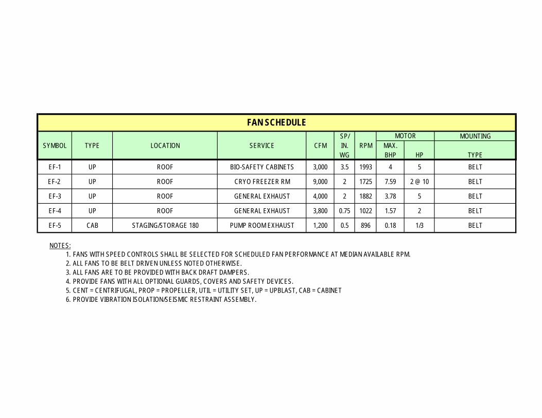
SP/ MOUNTINGSYMBOL TYPE LOCATION SERVICE CFM IN. RPM MAX.
WG BHP HP TYPEEF-1 UP ROOF BIO-SAFETY CABINETS 3,000 3.5 1993 4 5 BELT
EF-2 UP ROOF CRYO FREEZER RM 9,000 2 1725 7.59 2 @ 10 BELT
EF-3 UP ROOF GENERAL EXHAUST 4,000 2 1882 3.78 5 BELT
EF-4 UP ROOF GENERAL EXHAUST 3,800 0.75 1022 1.57 2 BELT
EF-5 CAB STAGING/STORAGE 180 PUMP ROOM EXHAUST 1,200 0.5 896 0.18 1/3 BELT
NOTES:1. FANS WITH SPEED CONTROLS SHALL BE SELECTED FOR SCHEDULED FAN PERFORMANCE AT MEDIAN AVAILABLE RPM.2. ALL FANS TO BE BELT DRIVEN UNLESS NOTED OTHERWISE.3. ALL FANS ARE TO BE PROVIDED WITH BACK DRAFT DAMPERS.4. PROVIDE FANS WITH ALL OPTIONAL GUARDS, COVERS AND SAFETY DEVICES.5. CENT = CENTRIFUGAL, PROP = PROPELLER, UTIL = UTILITY SET, UP = UPBLAST, CAB = CABINET6. PROVIDE VIBRATION ISOLATION/SEISMIC RESTRAINT ASSEMBLY.
FAN SCHEDULEMOTOR
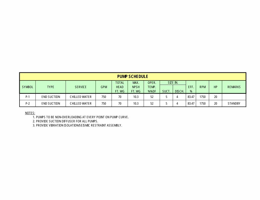
TOTAL MAX. OPER.SYMBOL TYPE SERVICE GPM HEAD NPSH TEMP. EFF. RPM HP REMARKS
FT. WG FT. WG %%DF SUCT. DISCH. %P-1 END SUCTION CHILLED WATER 750 70 10.3 52 5 4 83.47 1750 20
P-2 END SUCTION CHILLED WATER 750 70 10.3 52 5 4 83.47 1750 20 STANDBY
NOTES:1. PUMPS TO BE NON-OVERLOADING AT EVERY POINT ON PUMP CURVE.2. PROVIDE SUCTION DIFFUSER FOR ALL PUMPS.3. PROVIDE VIBRATION ISOLATION/SEISMIC RESTRAINT ASSEMBLY.
PUMP SCHEDULESIZE IN.
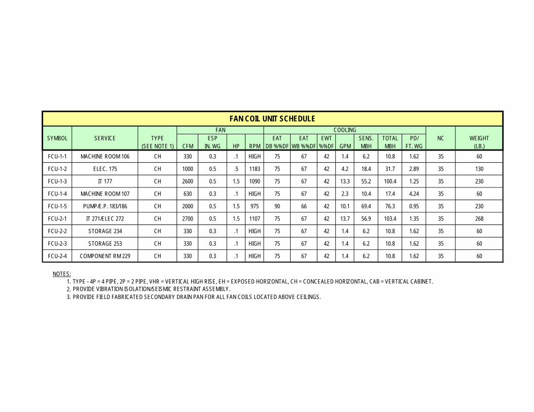
SYMBOL SERVICE TYPE ESP EAT EAT EWT SENS. TOTAL PD/ NC WEIGHT(SEE NOTE 1) CFM IN. WG HP RPM DB %%DF WB %%DF %%DF GPM MBH MBH FT. WG (LB.)
FCU-1-1 MACHINE ROOM 106 CH 330 0.3 .1 HIGH 75 67 42 1.4 6.2 10.8 1.62 35 60
FCU-1-2 ELEC. 175 CH 1000 0.5 .5 1183 75 67 42 4.2 18.4 31.7 2.89 35 130
FCU-1-3 IT 177 CH 2600 0.5 1.5 1090 75 67 42 13.3 55.2 100.4 1.25 35 230
FCU-1-4 MACHINE ROOM 107 CH 630 0.3 .1 HIGH 75 67 42 2.3 10.4 17.4 4.24 35 60
FCU-1-5 PUMP/E.P. 183/186 CH 2000 0.5 1.5 975 90 66 42 10.1 69.4 76.3 0.95 35 230
FCU-2-1 IT 271/ELEC 272 CH 2700 0.5 1.5 1107 75 67 42 13.7 56.9 103.4 1.35 35 268
FCU-2-2 STORAGE 234 CH 330 0.3 .1 HIGH 75 67 42 1.4 6.2 10.8 1.62 35 60
FCU-2-3 STORAGE 253 CH 330 0.3 .1 HIGH 75 67 42 1.4 6.2 10.8 1.62 35 60
FCU-2-4 COMPONENT RM 229 CH 330 0.3 .1 HIGH 75 67 42 1.4 6.2 10.8 1.62 35 60
NOTES:1. TYPE - 4P = 4 PIPE, 2P = 2 PIPE, VHR = VERTICAL HIGH RISE, EH = EXPOSED HORIZONTAL, CH = CONCEALED HORIZONTAL, CAB = VERTICAL CABINET.2.3. PROVIDE FIELD FABRICATED SECONDARY DRAIN PAN FOR ALL FAN COILS LOCATED ABOVE CEILINGS.
FAN COIL UNIT SCHEDULEFAN COOLING
PROVIDE VIBRATION ISOLATION/SEISMIC RESTRAINT ASSEMBLY.

Mechanical Systems Existing Conditions Evaluation
Appendix D
Unit Diagrams
________________________________________________________________________City of Hope: Amini Medical Center Duarte, California

Mechanical Systems Existing Conditions Evaluation
Appendix E
DPR Mechanical Cost Estimation
________________________________________________________________________City of Hope: Amini Medical Center Duarte, California


![TECHNICAL ASSIGNMENT 2 › ae › thesis › portfolios › 2012... · [TECHNICAL ASSIGNMENT 2] October 19, 2011 Biological Research Laboratory | 1 Executive Summary The Biological](https://img.pdfslide.net/doc/110x75/5f1b08978aeb6924b101c74c/technical-assignment-2-a-ae-a-thesis-a-portfolios-a-2012-technical.jpg)