Embed Size (px)
Citation preview

Thermodynamics IIChapter 5
Refrigeration
Mohsin Mohd SiesFakulti Kejuruteraan Mekanikal, Universiti Teknologi Malaysia

2
Objectives• Introduce the concepts of refrigerators and heat pumps and
the measure of their performance.
• Analyze the ideal vapor-compression refrigeration cycle.
• Analyze the actual vapor-compression refrigeration cycle.
• Review the factors involved in selecting the right refrigerant foran application.
• Discuss the operation of refrigeration and heat pump systems.
• Evaluate the performance of innovative vapor-compressionrefrigeration systems.
• Introduce the concepts of absorption-refrigeration systems.
Introduction
• Refrigeration is the process of removing heat from anenclosed space, or from a substance, and rejecting itto an environment.
• The primary purpose of refrigeration is lowering thetemperature of the enclosed space or substance andthen maintaining that lower temperature.
• The term cooling refers generally to any natural orartificial process by which heat is dissipated. Theprocess of artificially producing extreme coldtemperatures is referred to as cryogenics

Methods of refrigeration• Can be classified as non-cyclic, cyclic and thermoelectric.• Non-cyclic refrigeration - cooling is accomplished by melting ice
or by subliming dry ice (frozen carbon dioxide). Are used forsmall-scale refrigeration i.e. laboratories and workshops, or inportable coolers.
• Cyclic refrigeration - Consists of a refrigeration cycle, heat isremoved from a low-temperature space/source and rejected to ahigh-temperature sink with the help of external work
• Cyclic refrigeration can be classified as Vapor cycle and Gas cycle• Vapor cycle refrigeration can further be classified as:
– Vapor-compression refrigeration– Vapor-absorption refrigeration

Methods of refrigeration
• Gas cycle - Air is most often the working fluid. The hot and coldgas-to-gas heat exchangers are used. Less efficient than the vaporcompression cycle because the gas cycle works on the reverseBrayton cycle instead of the reverse Rankine cycle
• Thermoelectric refrigeration - Thermoelectric cooling uses thePeltier effect to create a heat flux between the junction of twodifferent types of materials. Commonly used in camping andportable coolers
• Thermoacoustic refrigeration uses sound waves in place of acompressor to create cooling power.

VAPOR COMPRESSION REFRIGERATION SYSTEM (VCRS)• Food Processing and storage -
Refrigerator• Building air conditioning
system• Car air conditioning system• Water cooler• Ice cube maker• Low temperature drying
process

Operation of VCRS

REFRIGERATORS AND HEAT PUMPS• The transfer of heat from a low-
temperature region to a high-temperature one requires specialdevices called refrigerators.
• Another device that transfers heat froma low-temperature medium to a high-temperature one is the heat pump.
• Refrigerators and heat pumps areessentially the same devices; they differin their objectives only.
• The objective of a refrigerator is toremove heat (QL) from the cold medium
• The objective of a heat pump is tosupply heat (QH) to a warm medium.
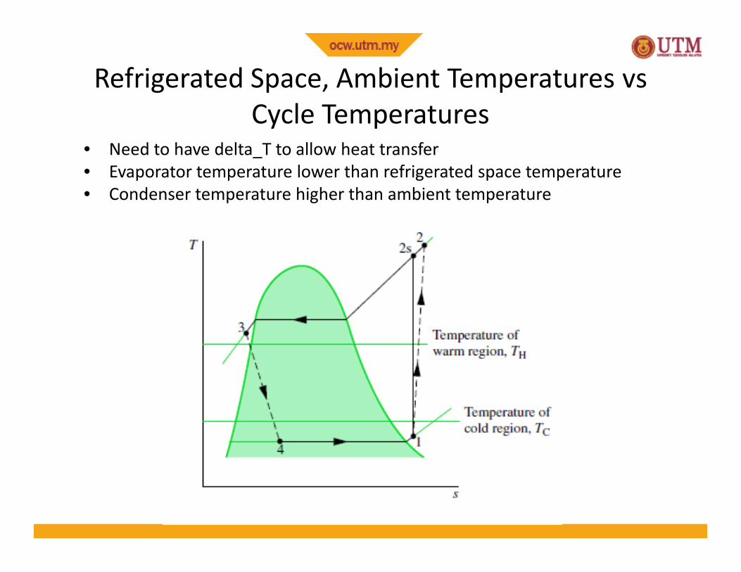
Refrigerated Space, Ambient Temperatures vsCycle Temperatures
• Need to have delta_T to allow heat transfer• Evaporator temperature lower than refrigerated space temperature• Condenser temperature higher than ambient temperature

Coefficient of Performance
The performance of refrigerators andheat pumps is expressed in terms of thecoefficient of performance (COP),defined as,
Both COPR and COPHP can be greater than 1.For fixed values of QL and QHCOPHP = COPR + 1
= = = ,= = = ,
11
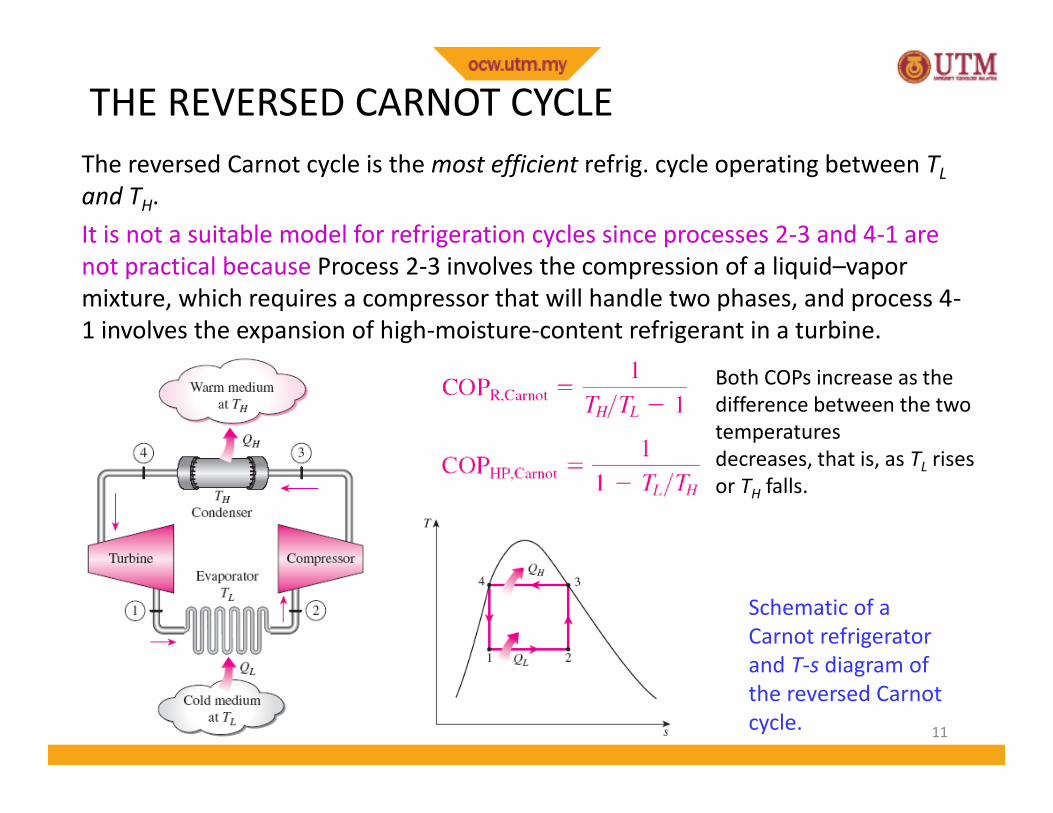
THE REVERSED CARNOT CYCLE
Schematic of aCarnot refrigeratorand T-s diagram ofthe reversed Carnotcycle.
Both COPs increase as thedifference between the twotemperaturesdecreases, that is, as TL risesor TH falls.
The reversed Carnot cycle is the most efficient refrig. cycle operating between TLand TH.It is not a suitable model for refrigeration cycles since processes 2-3 and 4-1 arenot practical because Process 2-3 involves the compression of a liquid–vapormixture, which requires a compressor that will handle two phases, and process 4-1 involves the expansion of high-moisture-content refrigerant in a turbine.

12
REFERENCE COP
The maximum COP of a refrigeration cycle operating betweentemperature limits of TL and TH
Actual refrigeration cycles are not as efficient as ideal ones like the Carnot cyclebecause of the irreversibilities involved. But the conclusion we can draw fromEq. 11–9 that the COP is inversely proportional to the temperature differenceTH - TL is equally valid for actual refrigeration cycles.

13
THE IDEAL VAPOR-COMPRESSION REFRIGERATION CYCLEUnlike the reversed Carnot cycle,• The refrigerant is vaporized completely before it is compressed• The turbine is replaced with a throttling device.
Schematic and T-sdiagram for the idealvapor-compressionrefrigeration cycle.
This is the mostwidely used cyclefor refrigerators, A-C systems, and heatpumps.

14
An ordinaryhouseholdrefrigerator.
The P-h diagram of an ideal vapor-compression refrigeration cycle.
Steady-flowenergy balance
AnalysisEach component is treated separately as open system with steady flow

15
11–12A refrigerator uses refrigerant-134a as the working fluid and operates onan ideal vapor-compression refrigeration cycle between 0.12 and 0.7MPa. The mass flow rate of the refrigerant is 0.05 kg/s. Show the cycle ona T-s diagram with respect to saturation lines. Determine:
a) the rate of heat removal from the refrigerated space,b) the power input to the compressor,c) the rate of heat rejection to the environment, andd) the coefficient of performance.
Answers: (a) 7.41 kW, 1.83 kW, (b) 9.23 kW, (c) 4.06
ProblemIdeal and Actual Vapor-Compression Refrigeration Cycles

16
11–15Consider a 300 kJ/min refrigeration system that operates on an idealvapor-compression refrigeration cycle with refrigerant-134a as theworking fluid. The refrigerant enters the compressor as saturated vaporat 140 kPa and is compressed to 800 kPa. Show the cycle on a T-sdiagram with respect to saturation lines, and determine the:
a) quality of the refrigerant at evaporator inlet,b) coefficient of performance, andc) power input to the compressor.
Problem – Class ExerciseIdeal and Actual Vapor-Compression Refrigeration Cycles

17
ACTUAL VAPOR-COMPRESSION REFRIGERATION CYCLEAn actual vapor-compression refrigeration cycle differs from the ideal oneowing mostly to the irreversibilities that occur in various components, mainlydue to fluid friction (causes pressure drops) and heat transfer to or from thesurroundings. As a result, the COP decreases.
Schematic andT-s diagram forthe actualvapor-compressionrefrigerationcycle.
DIFFERENCESNon-isentropic compressionSuperheated vapor at evaporator exitSubcooled liquid at condenser exitPressure drops in condenser and evaporator

Superheating and Subcooling• Superheating (at evaporator exit) – to ensure no liquid droplets enters
compressor to damage it• Subcooling (at condenser exit) – to increase cooling capacity
ΔT- Degree ofsuperheating

19
11–18Refrigerant-134a enters the compressor of a refrigerator as superheatedvapor at 0.14 MPa and 10°C at a rate of 0.12 kg/s, and it leaves at 0.7 MPaand 70°C. The refrigerant is cooled in the condenser to 24°C and 0.7 MPa,and it is throttled to 0.14 MPa. Disregarding any heat transfer andpressure drops in the connecting lines between the components, showthe cycle on a T-s diagram with respect to saturation lines, anddetermine:a) the rate of heat removal from the refrigerated space,b) the power input to the compressor,c) the isentropic efficiency of the compressor, andd) the COP of the refrigerator.
Answers: (a) 19.4 kW, 5.06 kW, (b) 82.5 percent, (c) 3.83
ProblemIdeal and Actual Vapor-Compression Refrigeration Cycles

20
SELECTING THE RIGHT REFRIGERANT• Several refrigerants may be used in refrigeration systems such as
chlorofluorocarbons (CFCs), ammonia, hydrocarbons (propane, ethane,ethylene, etc.), carbon dioxide, air (in the air-conditioning of aircraft), andeven water (in applications above the freezing point).
• R-11, R-12, R-22, R-134a, and R-502 account for over 90 percent of themarket.
• The industrial and heavy-commercial sectors use ammonia (it is toxic).• R-11 is used in large-capacity water chillers serving A-C systems in buildings.• R-134a (replaced R-12, which damages ozone layer) is used in domestic
refrigerators and freezers, as well as automotive air conditioners.• R-22 is used in window air conditioners, heat pumps, air conditioners of
commercial buildings, and large industrial refrigeration systems, and offersstrong competition to ammonia.
• R-502 (a blend of R-115 and R-22) is the dominant refrigerant used incommercial refrigeration systems such as those in supermarkets.

21
SELECTING THE RIGHT REFRIGERANT• CFCs allow more ultraviolet radiation into the earth’s atmosphere by
destroying the protective ozone layer and thus contributing to thegreenhouse effect that causes global warming. Fully halogenated CFCs (suchas R-11, R-12, and R-115) do the most damage to the ozone layer.Refrigerants that are friendly to the ozone layer have been developed.
• Two important parameters that need to be considered in the selection of arefrigerant are the temperatures of the two media (the refrigerated spaceand the environment) with which the refrigerant exchanges heat.
• The saturation pressures of the refrigerant at the temperatures TH and TL ofinterest also affect the required Win.

22
SELECTING THE RIGHT REFRIGERANT

23
SELECTING THE RIGHT REFRIGERANT

• Ozone Depletion Potential (ODP) of a chemical compound is the relativeamount of degradation it can cause to the ozone layer
• Global Warming Potential (GWP) is a measure of how much a given mass of agas contributes to global warming. GWP is a relative scale which compares theamount of heat trapped by greenhouse gas to the amount of heat trapped inthe same mass of Carbon Dioxide.
RefrigerantOzone Depletion
Potential(ODP)
Global WarmingPotential
(GWP)R-11 Trichlorofluoromethane 1.0 4000
R-12 Dichlorodifluoromethane 1.0 2400R-13 B1 Bromotrifluoromethane 10
R-22 Chlorodifluoromethane 0.05 1700R-32 Difluoromethane 0 650
R-113 Trichlorotrifluoroethane 0.8 4800R-114 Dichlorotetrafluoroethane 1.0 3.9
R-123 Dichlorotrifluoroethane 0.02 0.02R-124 Chlorotetrafluoroethane 0.02 620
R-134a Tetrafluoroethane 0 1300

25
INNOVATIVE VAPOR-COMPRESSION REFRIGERATIONSYSTEMS• The simple vapor-compression refrigeration cycle is the most widely used
refrigeration cycle, and it is adequate for most refrigeration applications.• The ordinary vapor-compression refrigeration systems are simple,
inexpensive, reliable, and practically maintenance-free.• However, for large industrial applications efficiency, not simplicity, is the major
concern.• Also, for some applications the simple vapor-compression refrigeration cycle
is inadequate and needs to be modified.• For moderately and very low temperature applications some innovative
refrigeration systems are used. The following cycles will be discussed:• Cascade refrigeration systems• Multistage compression refrigeration systems• Multipurpose refrigeration systems with a single compressor• Liquefaction of gases

Multistage Refrigeration
• Some industrial applications require moderately lowtemperatures, and the temperature range they involve maybe too large for a single vapor compression refrigeration cycleto be practical.
• A large temperature range also means a large pressure rangein the cycle and a poor performance for a reciprocatingcompressor.
• The long throttling process also results in decreased coolingcapacity
• One way of dealing with such situations is to perform therefrigeration process in stages, that is, to have two or morerefrigeration cycles that operate in series.
• Such refrigeration cycles are called cascade or multistagerefrigeration cycles.

Multistage Refrigeration
• Cooling effect is achieved when liquid refrigerant vaporizes byabsorbing heat from the cold space.
• This means that the vapor produced during throttling does notcontribute towards cooling because it is already vaporized.
• Separating the vapor from the liquid in a flash chamber canincrease the cooling effect
• And the vapor can be used to cool the compressed refrigerantfrom the lower stage. This cooling will reduce the compressorwork input.

28
Cascade Refrigeration SystemsA two-stage cascade refrigeration cycle is shown. The two cycles are connected throughthe heat exchanger in the middle, which serves as the evaporator for the topping cycleand the condenser for the bottoming cycle.
Cascadingimproves theCOP of arefrigerationsystem.Some systemsuse three or fourstages ofcascading.
A two-stage cascade refrigeration systemwith the same refrigerant in both stages.

29
Cascade Refrigeration Systems (Analysis)Assuming the heat exchanger is well insulated andthe kinetic and potential energies are negligible, theheat transfer from the fluid in the bottoming cycleshould be equal to the heat transfer to the fluid inthe topping cycle.• Thus, the ratio of mass flow rates through eachcycle should be
The coefficient of performance of thecascadesystem is

30
Multistage CompressionRefrigeration Systems
A two-stage compression refrigeration systemwith a flash chamber and mixing chamber.
When the fluid used throughout the cascaderefrigeration system is the same, the heatexchanger between the stages can be replaced bya flash chamber since it has better heat transfercharacteristics.

Multistage CompressionRefrigeration Systems(Analysis)
x6
1-x6
1
x6
1-x6
1
• The liquid refrigerant expands in the first expansion valve tothe flash chamber pressure, same as the compressor inter-stage pressure.
• Part of the liquid vaporizes. This saturated vapor (state 3) ismixed with the superheated vapor from the low-pressurecompressor (state 2), and the mixture enters the high-pressure compressor at state 9.
• The saturated liquid (state 7) expands through the secondexpansion valve into the evaporator, where it picks up heatfrom the refrigerated space.

Multistage Compression Refrigeration Systems(Analysis)

Multistage Compression Refrigeration Systems (Analysis)– Amount of Vapor Separated in Flash Chamber
m
x6m
(1-x6)mh6=x6(h3-h7)+h7h3=hgh7=hfh6=h5 (throttling)

Multistage Compression Refrigeration Systems (Analysis)– Mixing chamber
h9=x6h3 +(1-x6)h2h9=h2-x6(h2-h3)
• Since 3 is already vapor, the exit at 9will be superheated vapor between 2and 3.
• h9 is obtained from energy balance ofmixing chamber
mx6m
(1-x6)m

35
11–44A two-stage compression refrigeration system operates with refrigerant-134a between the pressure limits of 1 and 0.14 MPa. The refrigerantleaves the condenser as a saturated liquid and is throttled to a flashchamber operating at 0.5 MPa. The refrigerant leaving the low-pressurecompressor at 0.5 MPa is also routed to the flash chamber. The vapor inthe flash chamber is then compressed to the condenser pressure by thehigh-pressure compressor, and the liquid is throttled to the evaporatorpressure. Assuming the refrigerant leaves the evaporator as saturatedvapor at a rate of 0.25 kg/s and that both compressors are isentropic,determine the:
a) fraction of the refrigerant that evaporates in the flash chamber,b) rate of heat removed from the refrigerated space, andc) coefficient of performance.
ProblemTwo-Stage Compression Refrigeration Systems

36
11–48A two-stage multistage refrigeration system operates between pressurelimits of 1.2 MPa and 200 kPa with refrigerant-134a as the working fluid.Saturated liquid refrigerant leaving the condenser is throttled to a flashchamber operating at 0.4 MPa. The vapor from the flash chamber is mixedwith the refrigerant leaving the low-pressure compressor. The mixture isthen compressed to the condenser pressure by the high-pressurecompressor. The liquid in the flash chamber is throttled to the evaporatorpressure. The mass flow rate of the refrigerant in the evaporator is 0.15kg/s. Assuming saturated vapor refrigerant leaves the evaporator and theisentropic efficiency is 80 percent for both compressors, determine the:
a) mass flow rate of refrigerant in the high-pressure compressor,b) rate of heat removal from the refrigerated space, andc) coefficient of performance of the system.d) rate of heat removal and the COP if this refrigerator operated on a
single-stage cycle between the same pressure limits with the samecompressor efficiency and flow rate as in part (a).
ProblemTwo-Stage Compression Refrigeration System

37
ABSORPTION REFRIGERATION SYSTEMS
Ammonia absorption refrigeration cycle.
Absorptionrefrigeration iseconomical whenthere is a source ofinexpensive thermalenergy at atemperature of 100 to200°C.Some examplesinclude geothermalenergy, solar energy,and waste heat fromcogeneration orprocess steam plants,and even natural gaswhen it is at arelatively low price.

38
• Absorption refrigeration systems (ARS) involve the absorption of a refrigerant by atransport medium.
• The most widely used system is the ammonia–water system, where ammonia(NH3) serves as the refrigerant and water (H2O) as the transport medium.
• Other systems include water–lithium bromide and water–lithium chloride systems,where water serves as the refrigerant. These systems are limited to applicationssuch as A-C where the minimum temperature is above the freezing point of water.
• Compared with vapor-compression systems, ARS have one major advantage: Aliquid is compressed instead of a vapor and as a result the work input is very small(on the order of one percent of the heat supplied to the generator) and oftenneglected in the cycle analysis.
• ARS are often classified as heat-driven systems.• ARS are much more expensive than the vapor-compression refrigeration systems.
They are more complex and occupy more space, they are much less efficient thusrequiring much larger cooling towers to reject the waste heat, and they are moredifficult to service since they are less common.
• Therefore, ARS should be considered only when the unit cost of thermal energy islow and is projected to remain low relative to electricity.
• ARS are primarily used in large commercial and industrial installations.

39
HEAT PUMP SYSTEMS The most common energy source for heatpumps is atmospheric air (air-to- airsystems).Water-source systems usually use wellwater and ground-source (geothermal)heat pumps use earth as the energysource. They typically have higher COPsbut are more complex and moreexpensive to install.Both the capacity and the efficiency of aheat pump fall significantly at lowtemperatures. Therefore, most air-sourceheat pumps require a supplementaryheating system such as electric resistanceheaters or a gas furnace.Heat pumps are most competitive inareas that have a large cooling load duringthe cooling season and a relatively smallheating load during the heating season. Inthese areas, the heat pump can meet theentire cooling and heating needs ofresidential or commercial buildings.
A heat pump can be used to heat a house in winterand to cool it in summer.

Summary• Refrigerators and Heat Pumps• The Reversed Carnot Cycle• The Ideal Vapor-Compression Refrigeration Cycle• Actual Vapor-Compression Refrigeration Cycle• Selecting the Right Refrigerant• Heat Pump Systems• Innovative Vapor-Compression Refrigeration Systems• Gas Refrigeration Cycles• Absorption Refrigeration Systems
40