Embed Size (px)
Citation preview

!!
i!!
!!!!!!
!
Design!of!an!Online!Monitoring!System!for!Degrading!Hardware!Components!Using!Failure!
Modes!and!Effects!Analysis!
!
!
Undergraduate!Honors!Thesis!
Presented!in!Partial!Fulfillment!of!the!Requirements!for!
Graduation!with!Distinction!in!the!
Department!of!Mechanical!Engineering!at!
The!Ohio!State!University!
!
!
!
!
Muzhi!Zhu!
Spring,!2016!
Advisor:!Carol!Smidts,!Ph.D.!

!!
ii!!
Abstract((A! nuclear! hybrid! energy! system,! consisting! of! different! energy! subsystems! such! as!
nuclear,!solar,!and!wind,!involves!frequent!switching!between!different!energy!subsystems!and!
between!different!controls.!This!can!potentially! lead!to!faster!aging!and!failure!of!mechanical!
components.!The!increased!usage!of!the!turbine!bypass!system!is!considered!to!be!the!major!
difference! between! a! nuclear! hybrid! energy! system! and! a! traditional! nuclear! power! plant.!
Reliability!analysis!for!designing!such!a!complex!system!involves!both!high!level!fault!propagation!
analysis!at!the!conceptual!design!stage!and!low!level!failure!prediction!for!specific!components.!
The!two!main!focuses!of!this!thesis!are:!first!to!develop!behavioral!rules!and!functional!failure!
logic! for! hardware! components;! and! second! to! derive! a! degradation! model! of! hardware!
components.!!
The!behavioral!rules!and!functional!failure!logic!form!the!BehaviorModel,of!the!function!
failure!identification!and!propagation!(FFIP)!method.!FFIP!is!an!approach!that!can!help!designers!
at! the! conceptual! design! stage! to! identify! which! function(s)! will! be! lost! in! a! system! and!
approximately! when! and! where.! The! simulation! results! obtained! using! FFIP! can! serve! as!
indicators! for! the! designers! to! determine! if! the! system! is! robust! enough! or! if! more!
safeguards/redundancies! are! necessary.! Implementing! the! method! will! reduce! redesign! and!
maintenance!costs!in!later!design,!implementation!and!operational!stages.!!
The!degradation!model! is!a! low!level! failure!mode!model!that!combines!the!effects!of!
natural! aging! and! frequent! switching! conditions.! The! model! can! be! used! for! predicting!
components’!failure!due!to!specific!failure!modes!that!are!described!in!the!behavioral!rules.!The!
result! can! serve! as! an! indicator! for! conducting! repair! actions! and!maintenance! to!minimize!
Operation! &!Maintenance! (O&M)! costs.! Both! the! high! level! FFIP! method! and! the! low! level!
degradation!model!are!demonstrated!for!the!turbine!bypass!system!in!the!secondary!loop!of!a!
hybrid!nuclear!power!plant.!!

!!
iii!!
Acknowledgements(! Having!worked!in!the!Reliability!and!Risk!Laboratory!since!spring!2015,!I!am!grateful!for!
the!guidance!and!help!that!I!have!received!from!my!advisor!and!lab!mates.!This!thesis!would!not!
have!been!possible!without!their!efforts.!!
! First!of!all,!I!would!like!to!thank!my!advisor,!Dr.!Carol!Smidts.!Thanks!to!her!patience!and!
willingness!to!sit!down!and!discuss!the!project!with!me!during!the!past!year,!I!learned!what!it!
takes!to!become!an!independent!researcher.!!Her!guidance!helped!me!grow!professionally!and!
personally.!!
! I!would! also! like! to! thank!my! lab!mates,! Ph.D.! student!Huijuan! Li,!Mike! Pietrykowski,!
Master’s!student!Rachit!Aggarwal!and!undergraduate!student!Paul!Johnson.!Mike!introduced!the!
project!to!me!when!I!first!joined!the!laboratory.!During!our!bi]weekly!meetings!in!the!fall!and!
spring!semesters,!Huijuan!and!Rachit’s!advice!was!always!helpful!when!I!tried!to!solve!a!problem!
with!a!new!approach.!Paul!helped!me!edit!the!thesis.!
! I! would! like! to! thank! the! College! of! Engineering! for! providing! the! scholarship! which!
supported!me!during!the!conduct!of!this!work.!!
! This!work! is! supported! through! the! INL! Laboratory!Directed!Research!&!Development!
(LDRD)!Program!under!DOE!Idaho!Operations!Office!with!contract!number:!DE]AC07]05ID14517.!!
! Lastly,!I!would!like!to!thank!all!the!friends!I!have!at!The!Ohio!State!University.!College!is!a!
unique!experience!in!one’s!life,!and!you!made!the!three!years!I!spent!at!Ohio!Sate!special.!!

!!
iv!!
Table(of(Contents!
Abstract!........................................................................................................................................................!ii!
Acknowledgements!.....................................................................................................................................!iii!
List!of!Figures!..............................................................................................................................................!vi!
List!of!Tables!...............................................................................................................................................!vii!
Chapter!1!Introduction!.................................................................................................................................!1!
1.1! Nuclear!hybrid!energy!system!......................................................................................................!1!
1.2! Reliability!engineering!..................................................................................................................!4!
1.3! Online!monitoring!system!for!a!nuclear!hybrid!energy!system!...................................................!5!
1.4! Research!objectives!......................................................................................................................!6!
1.5!Thesis!outline!.....................................................................................................................................!6!
Chapter!2:!Behavioral!Rules!and!Functional!failure!logic!for!Hardware!Components!.................................!7!
2.1!Review!of!failure!mode!and!effect!analysis!........................................................................................!7!
2.2!Function!failure!identification!and!propagation!(FFIP)!approach!for!failure!analysis!........................!8!
2.2.1!Introduction!of!FFIP!.....................................................................................................................!8!
2.2.2!Structure!of!FFIP!..........................................................................................................................!9!
2.3!Behavioral!Rules!and!Functional!failure!logic!...................................................................................!11!
2.3.1!Identify!component!of!interest!.................................................................................................!11!
2.3.2!Turbine!bypass!valve!.................................................................................................................!11!
2.3.3!Multifunction!flowmeter!...........................................................................................................!17!
2.3.4!Steam!pipeline!...........................................................................................................................!20!
2.4!Case!study!........................................................................................................................................!23!
2.4.1!Turbine!bypass!system!layout!...................................................................................................!23!
2.4.2!Function!diagram!for!the!turbine!bypass!system!......................................................................!28!
2.4.3!Failure!Mode!Transition!Description!.........................................................................................!29!
2.4.4!Simulation!for!Fault!Propagation!..............................................................................................!30!
Chapter!3!Degradation!Model!for!Single!Component!................................................................................!38!
3.1!Stress]Strength!Interference!Model!.................................................................................................!38!
3.2!Degradation!Model!for!Single!Component!......................................................................................!41!
3.2.1!Degradation!Model!from!Literature!..........................................................................................!41!
3.2.2!Modified!Degradation!Model!....................................................................................................!42!
!!
v!!
3.2.3!Leakage!Failure!Model!..............................................................................................................!43!
3.4!Case!study!for!internal!valve!leakage!...............................................................................................!46!
3.4.1!Model!description!.....................................................................................................................!46!
3.4.2!Simulation!results!......................................................................................................................!47!
3.4.3!Results!discussion!......................................................................................................................!48!
Chapter!4!Conclusion!and!Future!Work!.....................................................................................................!55!
References!..................................................................................................................................................!56!
Appendix!....................................................................................................................................................!58!

!!
vi!!
List(of(Figures((Figure!1!!Schematic!of!a!nuclear!hybrid!energy!system![3]!..........................................................................!2!
Figure!2!Distribution!of!renewable!generation!variability![4]!......................................................................!3!
Figure!3!!Proposed!Online!Monitoring!System!............................................................................................!5!
Figure!4!Structure!of!FFIP!.............................................................................................................................!9!
Figure!5!Turbine!Bypass!Valve!Illustration!.................................................................................................!11!
Figure!6!Rosemount!Compact!Orifice!Flowmeters!....................................................................................!17!
Figure!7!Pipe!Detection!Method!Illustration![11]!......................................................................................!20!Figure!8!Typical!Secondary!Loop!in!Nuclear!Power!Plant!..........................................................................!23!
Figure!9!Two!Stage!Turbine!Bypass!System!...............................................................................................!24!
Figure!10!Function!Diagram!for!the!2!Stage!Turbine!Bypass!System!.........................................................!28!
Figure!11!General!Stress]strength!Interference!Illustration!......................................................................!39!
Figure!12!Stress]strength!Interference!with!Constant!Thresholds!............................................................!40!
Figure!13!Leakage!Degradation!Simulation!for!500!Samples!.....................................................................!47!
Figure!14!Probability!of!Failure!..................................................................................................................!47!
Figure!15!Mean!and!Median!for!Degradation………………………………………………………………………………………..48!
Figure!16!Variance!for!the!Degradation!.....................................................................................................!49!
Figure!17!Distribution!for!Leakage!Rate!at!Each!Given!Time!.....................................................................!50!
Figure!18!Distribution!Fit!for!Time!to!Failure!.............................................................................................!53!
Figure!19!Lognormal!Fit!for!Time!to!Failure!...............................................................................................!53!
Figure!20!!Lognormal!Distribution!Fit!for!the!Sample!Reliability!Function!................................................!54!Figure,21,Distribution,Fit,at,the,1st,Selected,Time!.....................................................................................!58!
Figure!22!Distribution!Fit!at!the!2nd!Selected!Time!...................................................................................!58!
Figure!23!Distribution!Fit!at!the!3rd!Selected!Time!...................................................................................!59!
Figure!24!Distribution!Fit!at!the!4th!Selected!Time!...................................................................................!59!
Figure!25!Distribution!Fit!at!the!5th!Selected!Time!...................................................................................!60!

!!
vii!!
List(of(Tables(Table!1!Failure!Modes!for!the!Turbine!Bypass!Valve! 13!
Table!2!Behavioral!rules!and!Functional!Failure!Logic!for!the!Turbine!Bypass!Valve! 16!
Table!3!Failure!Modes!for!the!Flowmeter! 18!
Table!4!Behavioral!rules!and!Functional!Failure!Logic!for!the!Flow!Meter! 19!
Table!5!Failure!Modes!for!the!Pipe!Line! 21!
Table!6!Behavioral!rules!and!Functional!Failure!Logic!for!the!Pipeline! 21!
Table!7!Behavioral!Rules!for!the!Pipeline!with!2!Inlet!Flows! 22!Table!8!FFL!for!Pipeline!with!2!Inlet!Flows! 22!
Table!9!Simplified!Behavioral!Rules!and!Function!Failure!Logic!for!the!Turbine,!the!Condenser!and!the!
Pump! 26!
Table!10!System!Behavior!at!Time!Unit!6! 32!
Table!11!!FFIP!Demonstration!for!Fault!Propagation!in!the!Turbine!Bypass!System! 36!
Table!12!!Stress]Strength!Interference!for!Different!Failure!Modes! 38!
Table!13:!Value!Specification!for!the!Degradation!Model! 46!
Table!14!Test!of!Fit!at!5!Selected!Times! 51!
Table!15!Critical!Value!for!Anderson]Darling!Test!(Mean!and!Median!Unknown)! 52!
Table!16!Test!of!Fit!for!the!Time!to!Failure! 52!
!
!
!
!
!

!!
1!!
Chapter(1(Introduction((1.1!Nuclear(hybrid(energy(system(
! According!to!the!U.S!Energy!Information!Administration!(EIA),!the!U.S!fossil!fuel!share!of!
energy!consumption! in!2015!was!67%.[1]!Fossil! fuels!are!still!being!heavily!relied!on,!and!this!
trend! is! unlikely! to! change! even! until! 2040! according! to! the! EIA.! Furthermore,! the! Central!
Intelligence!Agency! reported! that!with! today’s! rate!of! consumption!of! fossil! fuels,!petroleum!
would!run!out!by!2052,!natural!gas!by!2060,!and!then!coal!by!2088.!No!fossil!fuel!will!remain!by!
the!next!century.!Besides!the!limited!reserves!of!fossil!fuel,!massive!consumption!of!fossil!fuel!
also!raises!concerns!about!global!warming!and!pollution.!Therefore,!there!has!been!a!growing!
interest! in! reducing! fossil! fuel! consumption! in! the! energy! structure! and! in! increasing! the!
proportion!of!clean!energy.!!!!! !
! Renewable! energy! (e.g.!wind,! solar)! has! the! potential! for! distributed! generation.! This!
feature!can!reduce!the!cost!of!electricity!transportation.!However,!the!availability!for!renewable!
energy!fluctuates!and!is!uncontrollable.!Therefore,!additional!energy!sources!need!to!be!coupled!
with!renewable!energy!to!produce!a!stable!electricity!generation!profile![2].!Nuclear!energy!can!
serve!this!purpose.!Nuclear!energy,!as!a!clean!energy!source,!has!low!greenhouse!gas!emission,!
possesses!high!power!density!and!baseload!power!supply!with! low!fuel!cost.! It! is!desirable!to!
develop!a!hybrid!energy!system!that!processes!both!renewable!energy!and!nuclear!energy!to!
meet!low!carbon!emission!goals!and!to!utilize!renewable!energy.!The!proposed!hybrid!energy!
system!is!shown!in!Figure!1.!!
!
!
!
!
!
!

!!
2!!
!
!
!
!
!
!
!
!
!
!
! As!can!be!observed!in!the!figure!above,!nuclear!energy!power!generation!and!wind!energy!
generation!are!coupled!to!provide!stable!power!to!the!electric!grid.!Tight!coupling!of!clean!energy!
from! different! sources! into! a! hybrid! system! has! advantages! compared! to! traditional! power!
plants.!Hybrid!energy!systems!can!reduce!greenhouse!gas!emissions!and!provide!highly!reliable!
electricity,!which!is!one!of!the!major!challenges!for!renewable!power!generation.!High!renewable!
energy!penetration! can! reduce! the! cost! of! electricity! transportation! as!well.!Development!of!
advanced!energy!systems!that!integrate!low!or!zero]carbon!generation!sources!will!provide!the!
needed! energy! sources! with!minimal! impact! on! the! environment.! Integration! of! low]carbon!
resources!in!a!manner!that!provides!reliable!energy!supply!is!of!particular!importance!in!light!of!
recent!announcements!on!carbon!reduction!made!by!the!Environmental!Protection!Agency.!!
! Despite! all! the! benefits! mentioned! above,! nuclear! hybrid! energy! systems! also! face!
challenges.!!
Figure,1,,Schematic,of,a,nuclear,hybrid,energy,system,[3],

!!
3!!
!
Figure,2,Distribution,of,renewable,generation,variability,[4],! As!can!be!seen!from!Figure!2,!power!generation!from!renewable!energy!sources!(GP1)!
fluctuates.! To! supply! stable! power! to! the! grid,! the! corresponding! energy! generation! for! the!
nuclear!power!plant!(GP3)!must!fluctuate!as!well.!For!a!nuclear!power!plant,!the!primary!loop!
heat!generation!should!remain!constant.!Thus,!the!frequent!use!of!the!turbine!bypass!line!in!the!
secondary!loop!is!required!to!achieve!the!fluctuating!power!generation.!!!
!
!
!
!
!

!!
4!!
1.2!Reliability!engineering!!
! Reliability! engineering! is! a! field! that! studies! the! dependability! of! a! product! during! its!
lifecycle.! It! focuses!on! the!performance!of! the!physical! systems!or! functional!objects! [5].!The!
objective!of!reliability!engineering!analysis!according!to!Patrick!O'Connor!in!Practical,Reliability,
Engineering?,[6],!is!to:!
‘’1.!To!apply!engineering!knowledge!and!specialized!techniques!to!prevent!or!to!reduce!the!
likelihood!or!frequency!of!failures.!
2.!To!identify!and!correct!the!causes!of!failures!that!do!occur,!despite!the!efforts!to!prevent!
them.!
3.!To!determine!ways!of!coping!with! failures!that!do!occur,! if! their!causes!have!not!been!
corrected.!
4.!To!apply!methods! for!estimating! the! likely! reliability!of!new!designs,!and! for!analyzing!
reliability!data.’’!
For! the! objectives! stated! above,! the! approaches! for! reliability! analysis! can! be! both!
quantitative!and!qualitative!in!nature.!!
Commonly!used!qualitative!techniques!for!reliability!analysis!include!failure!mode!and!effects!
analysis! (FMEA),! hazard! analysis,! and! fault! tree! analysis! (FTA).! An! important! quantitative!
approach!in!reliability!engineering!is!to!identify!the!reliability!parameters!and!probability!model!
that! best! describe! the! system’s! reliability! behavior.! However,! due! to! the! high! degree! of!
uncertainty!in!the!quantitative!analysis,!a!high]level!qualitative!analysis!is!also!useful!in!reliability!
engineering.!!
In! this! thesis,!both!quantitative!and!qualitative!methods!are! implemented! to!analyze! the!
reliability!performance!at!the!component!and!nuclear!hybrid!energy!system!level.!!
!
!
!
!
!

!!
5!!
1.3!Online!monitoring!system!for!a!nuclear!hybrid!energy!system!
! Online!monitoring!of!an!integrated!energy!system!is!a!highly!complex!problem.!Due!to!
the!nature!of!coupling!electrical!generation!from!different!energy!sources,!the!system!dynamics!
will! involve! frequent! switching! between! different! energy! systems! and! switching! between!
different!control!systems.!Frequent!switching!between!the!energy!systems!may!lead!to!faster!
aging!of!the!mechanical!components!and!the!sensors,!leading!to!unprecedented!shutdowns!of!
one! of! the! energy! systems.! Failure! of! an! energy! system! can! add! an! unexpected! load! on! the!
nuclear!power!plant,!increasing!the!likelihood!of!an!accident.!Nuclear!power!plant!operation!as!
a!part!of!an!integrated,!hybrid!energy!system!requires!special!operator!training!to!understand!
the! load! distribution! and! expected! dynamic! power! generation! from! the! plant.! Human! error!
probability!may!increase!in!hybrid!energy!systems.!To!minimize!the!risk!of!component!failure,!
control!failure,!human!error,!and!to!help!improve!the!operator’s!ability!to!monitor!the!hybrid!
energy! system,! an! advanced! digital! alarm! system! is! required.! A! proposed! online!monitoring!
system!is!shown!in!Figure!3.!!
!
,,,
Figure,3,,Proposed,Online,Monitoring,System,! The! online!monitoring! system! compares! the! data! collected! by! various! sensors! in! the!
secondary!loop!of!the!nuclear!power!plant!to!previously!built!models!of!the!system.!The!models!
describe! different! manners! that! the! system! could! behave! such! as! nominal! and! faulty.! The!

!!
6!!
comparison!is!implemented!through!existing!data!analysis!algorithms!and!customized!algorithms.!
In!this!way,!the!online!monitoring!system!can!classify!the!health!status!of!each!component!and!
detect!faults!and!failures.!The!alarm!system!can!then!be!designed!to!respond!appropriately!to!
each! detected! fault! and! provide! operational! instructions.! The! operator! should! follow! the!
instructions!to!conduct!repair!actions.!In!this!way,!the!implementation!of!the!online!monitoring!
system!can!prevent!future!fault!propagation.!The!customized!algorithms!will!be!both!quantitative!
and! qualitative,! and!will! be! able! to! communicate! with! other! existing! algorithms.! The! online!
monitoring!system!will!be!developed!and!verified!using!the!simulation!models!for!the!integrated!
system.!The!main!objective!of!this!research!is!to!provide!models!and!rules!for!fault!detection!and!
fault! diagnosis! in! the!online!monitoring! system.! The! impact! of! system’s! duty! cycles! on! aging!
degradation!and!reliability!of!the!steam!bypass!system!is!the!main!concern!for!the!study.!!!
1.4!Research!objectives!!
1.! Develop!the!behavioral!rules!and!functional!failure!logic!for!the!components!of!interest!
in!the!online!monitoring!system.!
2.! Combine!natural!aging!and!degradation!effects!to!derive!a!general!degradation!model.!!
3.! Estimate! the! parameters! of! the! degradation! model! for! selected! failure! modes,! e.g.!
leakage.!!
1.5!Thesis!outline!!
! The! thesis! is! formed! by! four! chapters.! Chapter! 1! introduces! the! topic! of! the! thesis.!
Chapter!2!reviews!concepts!of!fault!failure!identification!and!propagation!(FFIP)!to!study!fault!
propagation! at! the! conceptual! design! stage.! The! associated! behavioral! rules! and! functional!
failure!logic!have!been!developed!for!components!of!interest.!!
! Chapter! 3! reviews! the! methodology! of! strength]stress! interference! and! develops! a!
degradation!model!to!describe!the!general!failure!behavior.!The!specific!failure!mode!of!internal!
leakage!of!the!turbine!bypass!valve!is!selected!for!study.!!!
! Chapter!4!summarizes!this!thesis!and!recommends!some!future!work.!

!!
7!!
Chapter!2:!Behavioral!Rules!and!Functional!failure!logic!for!
Hardware!Components!!2.1!Review!of!failure!mode!and!effect!analysis!!
! This! chapter!discusses! a!qualitative! approach! to!perform! reliability! analysis.! There!are! several!
commonly!used!methodologies!in!reliability!engineering!for!high!level!risk!analysis.!Two!of!the!most!used!
methods! are! failure! mode! and! effect! analysis! (FMEA)! and! fault! tree! analysis! (FTA).! FMEA! is! mainly!
discussed! since! it! is! related! to! the!Function!Failure! Identification!and!Propagation! (FFIP),!which! is! the!
method!implemented!in!this!chapter.!!
! FTA!is!a!top]down!approach!to!analyze!system!failure!which!starts!from!the!system’s!failure!event!
or!undesired!state.!It!is!a!deductive!approach!from!the!system!level!failure!to!the!component!level!failure!
to!identify!the!possible!root!causes!of!a!system’s!failure.!!!!
! Unlike!FTA,!FMEA!is!an!inductive,!component!level!approach!to!identify!failure.!It!is!a!systematic!
approach!to!identify!what!local!and!system!level!effects!could!be!caused!by!the!different!types!of!failure!
modes!of!each!component.!A!failure!mode!is!defined!as!the!manner!in!which!the!failure!of!a!component!
manifests!itself.!It!is!the!result!of!the!corresponding!failure!mechanism.!The!local!effect!describes!the!low]
level!effects!that!the!failure!mode!could!cause.!The!intermediate!level!effect(s)!describes!the!effect(s)!at!
the!intermediate!level(s)!that!the!failure!mode!could!cause.!The!system!level!effect!describes!the!effect!
at!the!system!level!that!the!failure!mode!could!cause.!For!example,!internal!leakage!is!a!failure!mode!for!
a!throttle!valve.!This!failure!mode!is!the!result!of!the!failure!mechanism!of!sealing!material!wearing!out.!
The!local!effect!is!the!air!flow!rate!downstream!of!the!throttle!valve!is!higher!than!the!designed!value.!
The!intermediate!level!effect!is!the!air!fuel!cannot!mix!ideally!in!the!throttle!body.!!The!system!level!effect!
is!the!engine!knock!will!occur!in!the!cylinder.!
!! FMEA!then!assesses!the!risk!by!assigning!a!1!to!10!rating!scale!for!severity,!for!the!probability!that!
the!failure!will!occur,!and!for!detectability.!Based!on!the!rating!grade,!the!risk!level!of!the!failure!mode!is!
determined.!FMEA!identifies!how!will!a!component!fail,!the!manner!that!a!fault!occurs,!and!its!local!and!
higher!level!effects.!Even!though!FMEA!is!an!effective!tool!in!analyzing!systems’!failure!behavior!there!are!
several! limitations.! Primarily,! the! rating! grades! for! severity,! probability,! and! detectability! are! highly!
subjective.!Experience!with!the!physical!system!is!required!to!make!reasonable!evaluations.!The!rating!
standard!for!different!failure!modes!may!not!be!consistent!as!well,!since!different!database!sources!may!

!!
8!!
have!different!evaluation!criteria!towards!the!same!failure!mode.!Another!issue!is!that!FMEA!focuses!on!
single]event!initiators.!There!is!no!failure!mode!combination!analysis!in!the!traditional!FMEA!analysis.!!
!
2.2!Function!failure!identification!and!propagation!(FFIP)!approach!for!failure!analysis!!
2.2.1!Introduction!of!FFIP!
! Integrated!system!failure!analysis!(ISFA)!was!previously!developed!by!Chetan!Mutha!at!
The!Ohio!State!University![8].! It! is!a!design!approach!which!can!be!used!in!the!early!stages!of!
product!design!to!identify!potential!system!failures!and!fault!propagation.!The!approach!has!the!
advantage! of! eliminating! costly! redesign! in! the! later! validation! stages.! The! ISFA! method!
integrates!the!Function!Failure!Identification!and!Propagation!(FFIP)!and!Failure!Propagation!and!
Simulation!Approach!(FPSA).!FFIP!focuses!on!hardware!failures.!FPSA!concentrates!on!software!
failures.!For! the!scope!of! this! thesis,!only!hardware! failures!are!considered,! therefore!human!
errors!and!software!faults!are!not!considered!as!potential!sources!of!failure.!!
! Similar! to! FMEA,! FFIP! also! uses! a! forward! approach! to! conduct! risk! assessment.! The!
simulation! is! based! on! a! qualitative!model,!which! fits! the! situation! at! the! conceptual! design!
stages!where! there! still! is! uncertainty! in! the! system! design.! FFIP! is! implemented! during! the!
conceptual!design!stage!by!modeling!the!system!using!different!design!views!and!by!injecting!a!
fault! in! a! single! or! multiple! components! and! traversing! the! design! views! systematically! to!
determine!the!impact!of!the!faults.!The!objective!of!FFIP!is!to!identify!the!fault!propagation!that!
leads!to!the!system’s!loss!of!function!and!modify!the!design!accordingly.!!
! FFIP! uses! a! graphical! approach! such! as! Systems! Modeling! Language! (SysML)! to!
qualitatively!analyze!system’s!behavior.!It!estimates!components’!state!based!on!state!variables.!
Based!on!a!graphical!approach!that!reflects!the!physical!layout!of!the!system!design,!it!is!possible!
to!inject!multiple!faults!at!the!same!time!to!study!propagation!and!functional!failure.!This!differs!
from!the!traditional!FMEA!analysis!which!was!discussed!in!the!previous!section.!!
!
!

!!
9!!
2.2.2!Structure!of!FFIP!!! Based!on!the!definition!of!FFIP,!the!model!consists!of!4!blocks:!FunctionModel,!
ConfigurationFlowGraph,!Flow,!and!BehaviorModel,!as!shown!in!Figure!4.!!
!
Figure,4,Structure,of,FFIP,
! The!figure!above!demonstrates!how!the!four!blocks!interact!with!each!other.!!
, Flow! is! the! entity! that! is! modified! by! functions! as! it! passes! through! the! system.! For!
example,!in!a!nuclear!power!plant!steam!is!a!type!of!Flow!which!is!heated!up!and!cooled!down!
by!the!components!it!passes!through.!!!
, FunctionModel,includes!the!components’!functions!in!the!system!and!the!way!in!which!
they!interact.!The!inlet!Flow!is!modified!by!the!hardwares’!FunctionModel!to!become!the!outlet!
Flow.,For!example,!the,function!for!a!valve!is!to!regulate!fluid!flow;!the!function,for!a!pipe!is!to!
transfer! fluid! flow.! It! should! be! noted! that! one! component! can! have!multiple! functions.! For!
example,!a!turbine!bypass!valve!possesses!two!functions:!regulate!flow!and!de]superheat!flow.!!

!!
10!!
, ConfigurationFlowGraph!is!the!section!that!describes!the!physical!layout!of!the!system.!!
ConfigurationFlowGraph! imports! the! same! Flow! as! FunctionModel,! because! functions! are!
mapped!into!components!using!Flow;!the!model!needs!to!be!consistent!in!both!component!view!
and!function!view.!Thus,!the!inlet!and!outlet!Flow!of!a!component!must!be!the!same!inlet!and!
outlet!Flow!for!the!function(s)!that!are!hosted!in!that!component.!!
, A,BehavioralModel! is!defined!qualitatively! for!each!hardware!component.! It!possesses!
two!portions:!behavioral!rules!and!functional!failure!logic!(FFL).!Behavioral!rules!are!divided!into!
nominal! and! faulty.! Nominal! is! when! a! component! is! working! properly.! Faulty! includes! the!
components! behaviors! for! each! failure! mode.! FFL! describes! the! relationship! between! a!
component’s! state! and!a! function’s! state.! ! The! status!of! a! function! is! evaluated!based!on! its!
component!behavior!and!the!detected!inlet!and!outlet!Flow.!If!the!component!status!is!nominal,!
the!outlet!Flow!matches! the! given! inlet!Flow! through! the!defined! function;! otherwise,! if! the!
component! status! is! faulty,! the! status! of! the! function! matches! the! predefined! FFL.! If! the!
component’s!behavior!is!not!described!in!the!behavioral!rules,!the!function!status!is!unknown.!!
! The! objective! of! the! FFIP! method! is! to! study! fault! propagation! at! a! high! level! of!
abstraction.!FFIP!is!conducted!by!behavioral!simulation.!To!simulate!the!behavior!of!the!system!
triggered!by!fault(s),!predefined!fault!mode!propagation!is!triggered.!A!fault!mode!propagation!
is!defined!based!on!the!physical!layout;!it!describes!how!a!fault!in!one!component!affects!that!
component!and!the!downstream!component!that!connects!to!it!through!Flow.!The!simulation!is!
in!discrete! time,!and!qualitatively! informs! the!user!how!a!designed!system!would! fail! for! the!
particular!fault!injection.!
! In!this!thesis,!the!analysis!is!based!on!the!secondary!loop!of!a!nuclear!power!plant.!To!
implement!the!FFIP!technique,!the!components!of!interest!must!be!identified,!and!the!behavioral!
rules!and!functional!failure!logic!for!the!system!must!be!defined.!In!the!last!section!of!the!chapter,!
a!case!study!will!be!conducted!using!FFIP.!!!
!

!!
11!!
2.3!Behavioral!Rules!and!Functional!failure!logic!
2.3.1!Identify!component!of!interest!!
! The! goal! of! the! online! monitoring! system! discussed! in! Chapter! 1! is! to! monitor! the!
secondary!loop!in!a!nuclear!power!plant!to!increase!the!reliability!of!the!power!plant.!!
! Within!the!nuclear!power!plant,!the!main!reliability!concern!is!the!steam!turbine!bypass!
system.!The!components!of!interest!in!the!steam!turbine!bypass!system!are!the!turbine!bypass!
valve,!multifunction!flowmeter,!and!steam!pipeline.!Behavioral!rules!and!functional!failure!logic!
will!be!developed!for!these!components.!!
!
2.3.2!Turbine!bypass!valve!!
A!typical!turbine!bypass!valve!in!a!nuclear!secondary!loop!is!shown!in!Figure!5![9].!
!
Figure,5,Turbine,Bypass,Valve,Illustration,
! The!turbine!bypass!valve!is!composed!of!two!valves!working!together:!a!bypass!valve!and!
a! spray! water! valve.! The! spray! water! valve! injects! cold! water! into! the! bypass! valve! to! de]
superheat!the!high!temperature,!high]pressure!steam.!The!control!logic!for!the!water!injection!
is!also!shown!above.!The!failure!of!a!spray!water!valve!is!usually!caused!by!software!faults.!Since!
the!software!faults!are!outside!the!scope!of!this!thesis,!the!spray!water!valve!is!deemed!to!be!
reliable.!Therefore,!the!analysis!for!the!turbine!bypass!valve!only!concerns!the!bypass!valve.!!

!!
12!!
! The!Flow!for!the!component!valve!is!steam,!and!the!function!of!the!valve!is!to!regulate!
fluid! flow! and!de]superheat! fluid! flow.! Table! 1! describes! the! components’! behavior! for! each!
failure!mode!based!on!their!input]output!relationship.!The!behavioral!rules!in!Table!1!are!based!
on!representing!the!physics!of!the!component!interactions!at!the!conceptual!stage.!The!input!
variables!for!the!turbine!bypass!valve!are!the!inlet!flow!rate,!the!inlet!temperature,!and!the!inlet!
amount!of!corrosion.!The!output!variables!are!the!outlet!flow!rate,!the!outlet!temperature!and!
the! outlet! amount! of! corrosion.! The! ‘’Model’’! column! in! Table! 1! contains! variables! that! are!
suspected!to!contribute!to!the!corresponding!failure!mode.!The!model!does!not!indicate!that!the!
degradation!process!follows!the!mathematical!relationship.!Quantification!requires!more!precise!
simulation!and!experimental!data.!!The!‘’Equivalent!Behavior’’!column!contains!the!behavior!that!
the!valve!performs!for!each!failure!mode.!!
!

!!
13!!
Table&1&Failure&Modes&for&the&Turbine&Bypass&Valve&Failure!Mode! Model!! Local!Effect!(With!leakage!inexplicit)! Equivalent!Behavior!!!
Nominal.!Idle!!
!
Nominal.!Opening!
!
Nominal.!Closing!
! If!!Qout!==!Qin!AND!Qout!==!Qout_nom!AND!Pout!==!(DD)*Pin!!AND!Tout!==!(DD)Tin!!
If!!QOut(t+1)!==!(+control)*!Qout(t)!AND!QOut(t+1)>!QOut(t))!AND!Tout!==!(DD)Tin!
If!!QOut(t+1)!==!(P!control)*!Qout(t)!!AND!QOut(t+1)<!QOut(t)!AND!Tout!==!(DD)Tin!
If!!PO(t+1)=!PO(t)!
If!PO(t+1)=(+control)*!PO(t)!AND!PO(t+1)>!PO(t)!
If!PO(t+1)=(Pcontrol)*!PO(t)}!AND!PO(t+1)<!PO(t)!
Internal!leakage.!Idle!!
Internal!leakage.!Opening!
Internal!leakage.!Closing!
∆" ∗ ∆$∗ % ∗ &!
If!!QOut!>Qout_nom!AND!Tout!>!(DD)*Tin!!
!
If!!QOut(t+1)!>!(+control)*!Qout(t)!AND!Tout!(t+1)>!(DD)*Tin!(t+1)!
!
If!!QOut(t+1)!>!(P!control)*!Qin(t)!AND!Tout!(t+1)>!(DD)*Tin!(t+1)!
POmin>0;!If(Nominal){!PO(t+1)=!PO(t)}!
If(Opening){PO(t+1)=(+control)*!PO(t)!AND!PO(t+1)>!PO(t)}!
If(Closing){!PO(t+1)=(Pcontrol)*!PO(t)}!AND!PO(t+1)<!PO(t)}!
Internal!rupture.!Idle!!!Internal!rupture.!Opening!!!Internal!rupture.!Closing!!
"'()∗ $'()∗ ∆" ∗ ∆$∗ % ∗ &!
If!!QOut!>>Qout_nom!AND!Tout!>!>(DD)*Tin!AND!Qcorrosion_out>Qcorrosion_in!!
!
If!!QOut(t+1)!>>!(+control)*!Qout(t)!AND!Tout!(t+1)>>!(DD)*Tin!(t+1)!AND!
Qcorrosion_out>Qcorrosion_in!!
If!!QOut(t+1)!>>!(P!control)*!Qin(t)!AND!Tout!(t+1)>!>(DD)*Tin!(t+1)!AND!!!!
Qcorrosion_out>Qcorrosion_in!!
POmin>>0;!PO>POin!
External!leakage.!Idle!!!External!leakage.!Opening!!External!leakage.!Closing!
"'()∗ $'()∗ ∆" ∗ ∆$∗ % ∗ &!
If!!QOut!<Qin!AND!Tout!<!(DD)*Tin!!
!
If!!QOut(t+1)<!(+control)*!Qout(t)!AND!Tout!(t+1)<(DD)*Tin!(t+1)!
!
If!!QOut(t+1)!<(P!control)*!Qin(t)!AND!Tout!(t+1)<(DD)*Tin!(t+1)!!
POByPass>0!

!!
14!!
External!rupture.!Idle!!!External!rupture.!Opening!!External!rupture.!Closing!
* ∗ ∆"∗ ∆$ ∗ %∗ &!
If!!QOut!<<Qin!AND!Tout!<<!(DD)*Tin!!AND!Qcorrosion_out>Qcorrosion_in!If!!QOut(t+1)<<!(+control)*!Qout(t)!AND!Tout!(t+1)<<(DD)*Tin!(t+1)!AND!
Qcorrosion_out>Qcorrosion_in!If!!QOut(t+1)!<<(P!control)*!Qin(t)!AND!Tout!(t+1)<<(DD)*Tin!(t+1)!AND!
Qcorrosion_out>Qcorrosion_in!!
POByPass>>0!
Spurious!operation!! * ∗ ∆$ ∗ %! IF!else!! !
PO:!position!of!valve;!Qout:!outlet!flow;!Qin!:!inlet!flow;!Qout_nom!:!nominal!output!flow;!+control: control3signal3to3open3the3valve;!1control:!control!signal!to!close!the!valve;!Pmax:!maximum!pressure$: <=&>*?&<@3AB<==CB<;3$D: ?E&C?F3AB<==CB<;!Tmax:!maximum!temperature;!!Tout:!outlet!temperature;!Tin!:!inlet!temperature;DD:!de1superheat!effect!3": <=&>*?&<@3&<*A<B?&CB<;3"D: ?E&C?F3&<*A<B?&CB<;!PO=0=fully!closed;!PO=1=fully!open.!!*To!create!equivalent!behavior!for!external!leakage/rupture,!a!bypass!valve!is!set!parallel!to!the!main!valve,!the!bypass!valve!excludes!the!amount!of!flow!that!is!assumed!to!be!lost!in!the!loop.!

!!
15!!
! Table!2!maps!components’!status!to!functions’!status.!Functions!for!the!turbine!bypass!
valve!are! to! regulate! flow!and!de>superheat! the! flow.!The!status! for! functions!are!defined!as!
operating,!degraded,! lost,! and!unknown.!Operating! indicates! that! the!component!behavior! is!
consistent!with!achieving!the!function.!Degraded! indicates!that!the!function! is!not!being!fully!
performed.!Lost!indicates!that!the!component!is!failing!to!perform!the!desired!function!entirely.!
The!component’s!status!has!an!influence!on!the!function(s)!that!the!component!possesses,!which!
is!shown!in!Table!2.!A!change!of!the!function!status!alters!the!outlet!Flow,!and!affects!all!the!
components!that!the!Flow!goes!through.!
!
!
!!
!
!
!
!
!
!
!
!
!
!
!
!
!
!
!
!

!!
16!!
Table!2!Behavioral!rules!and!Functional!Failure!Logic!for!the!Turbine!Bypass!Valve!Input! Output! Functionalitie
s!Behavioral!rules! Functional!failure!logic!
Qin!
Tin!
Qcorrosion_in!
!
Qout!
Tout!
Qcorrosion_out!
!
Regulate!Flow!
De>superheated!Flow!!
!
Mode!==!Nominal!!
IF!Local!effect.!Nominal!
!
Mode!==!Internal!Leak!
IF!Local!effect.!Internal!leakage!!
!!
Mode!==Internal!Rupture!!
IF!Local!effect.!External!leakage!!
!!
Mode!==!External!Leakage!
IF!Local!effect.!External!leakage!!!
!
Mode!==!External!Rupture!!
IF!Local!effect.!External!Rupture!!!
Mode!==!Spurious!operation!
IF!Local!effect.!Spurious!operation!
IF!mode!==!Nominal!
Then!Regulate!Fluid!==!O!
De>superheated!Flow!==!O!
IF!mode!==!Internal!Leak!
Then!Regulate!Flow!==!D!
De>superheated!Flow!==!D!
IF!mode!==!Internal!Rupture!
Then!Regulate!Flow!==!L!
De>superheated!Flow!==!L!
IF!mode!==!External!Leakage!
Then!Regulate!Flow!==!D!
De>superheated!Flow!==!D!
IF!mode!==!External!Rupture!
Then!Regulate!Flow!==!L!
De>superheated!Flow!==!L!
IF!mode!==!Spurious!operation!
Then!Regulate!Flow!==!U!
De>superheated!Flow!==!U!
!
O:!Operating;!D:!Degraded;!L:!Lost;!U:!Unknown!!
!

!!
17!!
2.3.3!Multifunction!flowmeter!!! A!description!of!behavioral!rules!and!functional! failure! logic!for!the!multifunction!flow!meter!are!based!on!a!description!of!Rosemount’s!compact!orifice!flow!meters![10].!
!
Figure!6!Rosemount!Compact!Orifice!Flowmeters!!
! The!flow!meter!depicted!in!Figure!6!is!an!illustration!for!a!flow!meter!that!is!commonly!used!in!nuclear!power!plants.!As!can!be!seen!from!the!figure!above,!an!orifice!plate!is!a!thin!plate!with!a!hole!at!the!center.!When!fluid!flow!goes!through!the!orifice!plate,!the!velocity!of!the!flow!increases! due! to! the! conservation! of! mass.! Orifice! flow!meters! use! the! pressure! difference!between! the! flow! upstream! and! the! flow! downstream! of! the! plate.! The! flow! rate! can! be!determined!based!on!Bernoulli's!equation!and!industry!standard!coefficients.!
For!simplicity,!the!flow!rate!can!be!expressed!as!shown!in!Equation!1.!!!
( )1 2* 2 *Q C A P P ρ= − ! ! ! ! ! ! ! !!!!!!!!!!!!!Equation!1!
C:!Flow!meter!coefficient! A:!Cross>section!area!for!the!orifice!hole!
P1:!Upstream!Pressure!! P2:!Downstream!Pressure!!
:ρ !Density!!!!!!!!!!!!!!!!!!!!!!!!!!!!!!!!!Q:!Flow!rate! !
Table!3!describes! the! flowmeter’s!behavior! for!each! failure!mode!based!on!the! input>output!relationship.!The!input!variable!is!the!actual!flow!rate.!The!output!variable!is!the!detected!flow!rate.!The!‘’Location’’!column!describes!the!location!where!the!failure!mode!occurs.!!!! !

!!
18!!
Table&3&Failure&Modes&for&the&Flowmeter&
Failure!Modes! ! Model!! Local!Effect! Location!!Normal!! ! !"#$#%$ = !'%$(') = !*+,-*') ! !Fluid!turbulence!!! . ∗ 01 ∗ ∆3! !"#$#%$ = !'%$(') + 56781!
!'%$(') = !*+,-*') ![1]!
Plate!fault! Orifice!plate!crack! . ∗ 9,': ∗ 3,': ∗ ; ∗ ∆9 ∗ ∆3∗ <!
!"#$#%$ < !'%$(') !!'%$(') < !*+,-*') !
[2]!
Orifice!abrasion!! . ∗ ; ∗ <! !"#$#%$ < !'%$(') !!'%$(') < !*+,-*') !
[2]!
Orifice!plate!lugging!!
9,': ∗ ∆9 ∗ ∆3 ∗ ; ∗ < ∗ >! If!(total!plugging)!{Qactual!=!0;!!"#$#%$ = !)'?@# A≫!'%$(');!}!else!{!"#$#%$ < !'%$(')}!
!'%$(') < !*+,-*') !
[2]!
Nearby!pipe!fault!
Flow!Pipe!leakage!upstream!!!
9,': ∗ 3,': ∗ ∆9 ∗ ; ∗ ∆3 ∗ <! !"#$#%$ < !'%$(') !!'%$(') < !*+,-*') !
[4]!!
Flow!Pipe!leakage!downstream!
9,': ∗ 3,': ∗ ∆9 ∗ ; ∗ ∆3 ∗ <! !"#$#%$ > !'%$(') !!'%$(') < !*+,-*') !
[3]!!!
Upstream!!Pressure!taps!leak!
9,': ∗ 3,': ∗ ∆9 ∗ ; ∗ ∆3 ∗ <! !"#$#%$ < !'%$(')=!*+,-*') ! [6]!!
Downstream!!Pressure!taps!leak!
9,': ∗ 3,': ∗ ∆9 ∗ ; ∗ ∆3 ∗ <! !"#$#%$ > !'%$(') = !*+,-*') ! [5]!!
Circuit!fault!!
short!circuit! . ∗ ; ∗ <! Qdetect!=!maximum;! !
open!circuit! . ∗ ; ∗ <! Qdetect!=!0;! !
Fails!to!operate! . ∗ ∆9 ∗ ; ∗ ∆3 ∗ <! Qdetect!=0! !
.:MassAflowArate; ARe:ARemoldAnumberAatAtheAorificeAplate; ∆3:!Pressure!difference!across!the!orifice!plate;!∆9:!Temperature!difference!across!the!orifice!plate;!f:!Demand!for!
the!turbine!bypass;!Tmax:!Maximum!temperature!across!the!!flow!meter;!Pmax:!Maximum!pressure!across!the!!flow!meter!;!t:!time!after!operation;!Qactual:!Actual!flow!rate;!Qdetech:!
Flow!rate!detected!by!the!flow!meter;!Qnominal:!Nominal!flow!rate;!)'?@# = AZ ∗ [\ 2(3_ − 3?#a) ∗ c!

!!
19!!
! Table! 4!maps! the! flowmeter’s! status! to! its! functions’! status.!A! flow!meter! is! used! to!measure!the!fluid!flow!rate,!thus,!when!the!meter!can!report!the!actual!flow!rate!the!meter!is!in!operating! status.! When! the! meter! cannot! reflect! the! real! flow! rate,! the! meter! has! lost! its!function.!There!is!no!intermediate!status!such!as!‘’degraded’’!for!flow!meter.!
!Table!4!Behavioral!rules!and!Functional!Failure!Logic!for!the!Flow!Meter!
Input! Output!
Functionalities!
Behavioral!rules! Functional!failure!logic!
Qin!
Pin!
Qout!
Pout!
Measure!flow!!! Mode!==!Normal!!
IF!Local!effect.!Normal!
!
Mode!==!Plate!fault!
IF!Local!effect.!Plate!fault!
!
Mode!==!Nearby!pipe!fault!
IF!Local!effect.!Nearby!pipe!fault!
!!
Mode!==!Circuit!Fault!
IF!Local!effect.!Circuit!fault!
!
Mode!==!Fails!to!Operate!
IF!Local!effect.!Fails!to!operate!
IF!mode!==!Nominal!!
Then!!Measure!Flow!==!O!
'
IF!mode!==!Plate!Fault!
Then!Measure!Flow!==!L!
!
IF!mode!==!Nearby!Pipe!Fault!
Then!Measure!Flow!==!L!
!
IF!mode!==!Circuit!Fault!
Then!Measure!Flow!==!L!
!
IF!mode!==!Fails!to!operate!
Then!Measure!Flow!==!L!
O:!Operating;!D:!Degraded;!L:!Lost;!U:!Unknown!
! !
! As!can!be!seen!from!the!table!above,!multiple!failure!modes!have!the!same!local!effect.!
Determining!the!exact!failure!mode!of!the!flow!meter!is!not!necessary.!As!long!as!symptoms!are!
detected! through! the! online! monitoring! system,! the! appropriate! repair! operations! will! be!
suggested,!and!the!failure!should!be!repaired.!!

!!
20!!
2.3.4!Steam!pipeline!
! Pipes!are!used!to!transfer!flow!in!a!power!plant.!!Ideally,!a!flow’s!property!should!be!the!
same!along!the!pipeline.!To!monitor!the!performance!of!a!pipeline,!sensors!are!placed!to!detect!
the!variable!of!interest!for!the!flow!within!the!pipeline.!Figure!7!is!an!example!of!using!sensors!
to!detect!leakage!in!a!pipe.!!
!
!
Figure!7!Pipe!Detection!Method!Illustration![11]!
!
! Table!5!describes!the!pipeline’s!behavior!for!each!failure!mode!based!on!the!inputXoutput!
relationship.!The!input!variables!are!the!inlet!flow!rate,!inlet!temperature,!and!the!inlet!corrosion.!
The!output!variables!are!the!outlet!flow!rate,!the!outlet!temperature!and!the!outlet!corrosion.!
!
!
!
!
!
!

!!
21!!
Table!5!Failure!Modes!for!the!Pipe!Line!
Failure!Mode! Model!! Local!Effect!Nominal! ! If!!"#$ = !&'!AND!!("#$ = (&'AND!
Qcorrosion_out!=!Qcorrosion_in!Leakage!!! !)*+ ∗ -)*+ ∗ ∆! ∗ ∆- ∗ / ∗ 0! IF!!"#$ < !&'!AND!("#$ < (&'!AND!
Qcorrosion_out!>!Qcorrosion_in!Plugging!! !)*+ ∗ -)*+ ∗ ∆! ∗ ∆- ∗ / ∗ 0 ∗ 2! IF!!"#$ > !&'!AND!("#$ < (&'AND!
Qcorrosion_out!>!Qcorrosion_in!Rupture!! !)*+ ∗ -)*+ ∗ ∆! ∗ ∆- ∗ / ∗ 0! IF!!"#$ < !&'!AND!("#$ ≪ (&'AND!
Qcorrosion_out!>!Qcorrosion_in!!2:!Impurity!of!the!flow;!t:!Time!after!operation;!!)*+:!Maximum!temperature!in!the!pipe;!-)*+:!Maximum!pressure!in!the!pipe;!
f:!Demand!for!the!turbine!bypass!line!!"#$:!Outlet!temperature;!!&':!Inlet!temperature;!("#$:!Outlet!flow!rate;!(&':!Inlet!flow!rate;!Qcorrosion_out:!Outlet!corrosion!material;!Qcorrosion_in:!Inlet!corrosion!material;!∆-:!Pressure!difference!across!the!pipe;!∆!:!Temperature!difference!across!the!pipe;!!
Table!6!maps!pipe’s!status!to!its!functions’!status.!
Table!6!Behavioral!rules!and!Functional!Failure!Logic!for!the!Pipeline!Input! Output! Functionalities! Behavioral!rules! Functional!failure!logic!
Qin!
Tin!
Qcorrosion_in!
Qout!
Tout!
Qcorrosion_out!
Transfer!flow!
!!!
Mode!==!Nominal!!
IF!Local!effect.!Nominal!
Mode!==!Leakage!!!
IF!Local!effect.!Leakage!!
Mode!==!Rupture!!
IF!Local!effect.!Rupture!
Mode!==!Plugging!
IF!Local!effect.!plugging!
IF!mode!==!Nominal!!
Then!Transfer!Fluid!==!O!
IF!mode!==!Leakage!!!
Then!Transfer!Flow!==!D!
IF!mode!==!Rupture!
Then!Transfer!Flow!==!L!
IF!mode!==!Plugging!
Then!Transfer!Flow!==!D!
O:!Operating;!D:!Degraded;!L:!Lost;!U:!Unknown!
!
! As!shown!in!the!table!above,!the!only!failure!mode!of!a!pipe!that!can!cause!the!loss!of!
function!‘’transfer!flow’’!is!the!rupture.!!
! If!a!pipe!connects!Flow!from!more!than!one!pipe,!then!there!are!multiple!inlet!variables!
that!describe!the!same!property!of!inlet!Flow!from!different!components.!Table!7!and!Table!8!
show!the!behavioral!rules!and!FFL!for!a!pipe!with!2!inlet!Flow.!

!!
22!!
Table!7!Behavioral!Rules!for!the!Pipeline!with!2!Inlet!Flows!
Failure!Mode!
Local!Effect!
Nominal! If6("#$ = (&'7 + (&'9!!AND!Qcorrosion_out!=!Qcorrosion_in!
Leakage!!! IF!("#$ < (&'9 + (&'9!AND!Qcorrosion_out!>!Qcorrosion_in!!AND! t !&'7 ≠ !&'9 > 0<=_?@& !Plugging!! IF!!"#$ > max !&', !&'9 !AND!("#$ < (&'7 + (EF9AND!Qcorrosion_out!>!Qcorrosion_in!!
Rupture!! IF!("#$ ≪ (&'7 + (&'9AND!Qcorrosion_out!>!Qcorrosion_in!AND!!![!t !&'7 ≠ !&'9 > 0<@_?@&]!Corrosion!! IF!("#$ = (&'7 + (&'96AND!Qcorrosion_out!>!Qcorrosion_in!AND!6 t !&'7 ≠ !&'9 > 0<?_?@& !
!
Table!8!FFL!for!Pipeline!with!2!Inlet!Flows!Input! Output! Functionalities! Behavioral!rules! Functional!failure!logic!
Qin_1!
Tin_1!
Qin_2!
Tin_2!
Qcorrosion_in!
Qout!
Tout!
Qcorrosion_out!
Transfer!flow!
!!!
Mode!==!Nominal!!
IF!Local!effect.!Nominal!
Mode!==!Leakage!!!
IF!Local!effect.!Leakage!!
Mode!==!Rupture!!
IF!Local!effect.!Rupture!
Mode!==!Plugging!
IF!Local!effect.!plugging!
Mode!==!Corrosion!
IF!Local!effect.!Corrosion!
IF!mode!==!Nominal!!
Then!Transfer!Fluid!==!O!
IF!mode!==!Leakage!!!
Then!Transfer!Flow!==!D!
IF!mode!==!Rupture!
Then!Transfer!Flow!==!L!
IF!mode!==!Plugging!
Then!Transfer!Flow!==!D!
IF!mode!==!Corrosion!
Then!Transfer!Flow!==!D!
0 !&'7 ≠ !&'9 :!accumulate!time!unit!that!Tin1≠Tin2;!0<@_?@&:!critical!time!to!trigger!pipeline!corrosion;!0<=_?@&:!critical!time!to!trigger!pipeline!leakage;60<@_?@&:!critical!time!to!trigger!pipeline!ruputure;!Qin_i:!inlet!flow!from!upstream!component!i;!!Qout:!outlet!flow;!Tin_i:!inlet!temperature!from!upstream!component!i;!Tout:!outlet!temperature;!Qcorrosion_in:inlet!corrosion;!Qcorrosion_out:!outlet!corrosion;!
!
!
!

!!
23!!
2.4!Case!study!!
2.4.1!Turbine!bypass!system!layout!!
! In!this!section!a!case!study!is!demonstrated!as!an!application!of!the!FFIP!method!to!the!
secondary!side!of!the!plant!used!in!the!context!of!a!nuclear!hybrid!energy!system.!The!online!
monitoring!system!focuses!on!the!secondary!loop!of!the!nuclear!power!plant.!A!typical!secondary!
loop!in!a!nuclear!power!plant!in!Westinghouse!designs![12]!can!be!simplified!as!shown!in!Figure!
8.![13]!!
!Figure!8!Typical!Secondary!Loop!in!Nuclear!Power!Plant!
! It!should!be!noted!that!the!secondary!loop!above!also!contains!a!reheat!line,!which!can!
increase!the!energy!conversion!efficiency!but!is!not!necessary!for!a!turbine!bypass!system.!The!
steam! that! comes! out! of! the! steam! generator! (boiler)! passes! through! 3! stage! turbines! that!
generate!power!and!3!stage!turbine!bypass! lines!that!go! into!the!condenser.!After!the!steam!
from!the!turbine!line!and!the!turbine!bypass!line!mix!and!go!to!the!condenser,!the!steam!goes!
back!to!the!steam!generator!from!the!condenser!through!the!feedwater!line.!!!

!!
24!!
! The!objective!of!the!case!study!in!this!section!is!to!demonstrate!the!application!of!the!
FFIP!method!within!the!context!of!a!nuclear!hybrid!energy!system.!Since!the!process!for!the!high!
pressure,! intermediate! pressure! and! low! pressure! bypass! segments! are! similar,! the! turbine!
bypass!system!is!reduced!into!a!2!stage!bypass!system!for!simplicity!as!shown!in!Figure!9.!!
From%steam%generator
%
HPTurbine
HP%BypassValve%
Spray%WaterValve
LPTurbine
LP%BypassValve%
Spray%WaterValve
HP%Turbine%Valve
LP%Turbine%Valve
To%condenser
Feed%Water%Pump
Feed%WaterValve
Pipe%1
To%steam%generator
Pipe%2
Pipe%3
Pipe%4
Pipe%6
Pipe%5
Pipe%7
Pipe%8
Pipe%9
Pipe%10
Pipe%12
Pipe%11
Pipe%13
Pipe%14Pipe%15
Pipe%16
!
HP:!HighXpressure!LP:!Low!pressure!!
Figure!9!Two!Stage!Turbine!Bypass!System!!
! There!are!two!turbine!lines!and!two!turbine!bypass!lines!in!the!system!above.!The!steam!
generator!has!three!functions:!storing!steam,!heating!steam,!and!supplying!heated!steam!to!the!
rest!of!the!system.!Superheated!steam!comes!out!of!the!steam!generator!and!goes!through!Pipe1!
and!is!split!into!two!parts.!One!portion!goes!to!the!highXpressure!turbine!line!and!the!other!goes!
to!the!highXpressure!turbine!bypass!line.!There!is!a!stop!valve!in!front!of!the!turbine.!If!the!turbine!
degrades,! the! stop! valve! would! close! and! allow! a! human! operator! to! conduct! repair! and!
maintenance.!The!steam!that!comes!out!of!the!highXpressure!turbine!and!the!steam!that!comes!
out!of!the!highXpressure!turbine!bypass!valve!have!similar!properties,!and!the!two!parts!of!steam!
mix!through!Pipe7!and!go!into!the!second!stage!of!the!turbine!bypass!system.!The!low!pressure!
stage!works!in!the!same!way!as!the!high!pressure!stage.!After!the!steam!comes!out!of!the!low!

!!
25!!
pressure!stage,!the!mixed!steam!goes!into!the!condenser!and!is!condensed!into!liquid!form.!Then!
the!Flow!changes!from!steam!to!water!and!is!pumped!back!to!the!steam!generator!through!the!
feedwater!line.! !!
! Condenser,!turbine!and!feed!water!pump!are!not!in!the!turbine!bypass!line.!Thus,!their!
behavioral!rules!and!function!failure!logic!are!not!fully!developed.!However,!these!components!
are!essential!for!the!secondary!loop!of!a!nuclear!power!plant!to!operate!properly.!For!the!scope!
of! this! case!study,! simplified!behavioral! rules!and! the!corresponding! function! failure! logic! for!
thesis!components!are!shown!in!Table!9.!
!!

!!
26!!
Table&9&Simplified&Behavioral&Rules&and&Function&Failure&Logic&for&the&Turbine,&the&Condenser&and&the&Pump&&Component!! Input! Output! Functionalities! Behavioral!rules! Functional!failure!logic!
Turbine!!
!
!
! !
!
Qin!
Tin!
Qcorrosion_in!
Qout!
Tout!
Qcorrosion_out!
Generator!power!
DeAsuperheat!flow!
Mode!==!Nominal!!
IF!Qout=!Qin!AND!Tout=!(DD)Tin!AND!t(Qcorrosion_in>0)≤tbc_cri!
!
Mode!==!Blade!Corrosion!!!!
IF#!Qout=!Qin!!AND!Qcorrosion_out>!Qcorrosion_in!AND!t(Qcorrosion_in>0)>tbc_cri!
!
Mode!==!Shut!Down!!
IF!Qin=0!
!
IF!mode!==!Nominal!!
Then!Generator!power==O!
!!!!!!!DeAsuperheat!flow==O!
IF!mode!==!Blade!Corrosion!!!!
Then!Generator!power==D!
!!!!!!!!!DeAsuperheat!flow==D!
IF!mode!==!Shut!Down!!
Then!Generator!power==L!
!!!!!!!!!!DeAsuperheat!flow==L!
Condenser! Qin!
Tin!
Qcorrosion_in!
Qout!
Tout!
Qcorrosion_out!
Condense!flow!! Mode!==!Nominal!!!
IF!Qcorrosion_in=!Qcorrosion_out!!AND!!Tout=!(DD)Tin!AND!t(Qcorrosion_in>0)≤tbc_cri!
Mode!==!Tube!Corrosion!
IF!!Qcorrosion_out>!Qcorrosion_in!AND!t(Qcorrosion_in>0)>tbc_cri!
Mode!==!Tube!Break!!
IF!Qcorrosion_out>!>Qcorrosion_in!AND!Qout>!Qin!AND!t(Qcorrosion_in>0)>ttb_cri!+tbc_cri!
IF!mode!==!Nominal!!
Then!Condense!flow!==!O!
IF!mode!==!Tube!Corrosion!
Then!Condense!Flow!==!D!
IF!mode!==!Tube!Break!!
Then!Condense!flow!==!L#

!!
27!!
Feed!Water!Pump!!
Qin!
Pin!
Qcorrosion_in!
Qout!
Pout!
Qcorrosion_out!
Increase!Pressure!
Supply!Flow!!
Mode==Nominal!!
IF!Qout=!Qin!AND!Pout=!(IP)Pin!AND!Qcorrosion_out=!Qcorrosion_in!AND!t(Qcorrosion_in>0)≤tmc_cri!
Mode==Outlet!Pressure!Low!
IF#Qout=!Qin!AND!Pout=<(IP)Pin!AND!Qcorrosion_out=!Qcorrosion_in!
!
Mode==!Motor!Corrosion!!!
IF#Qcorrosion_out!!>!Qcorrosion_in!AND!t(Qcorrosion_in>0)>tmc_cri!
IF!mode!==!Nominal!!
Then!Increase!Pressure==O!
!!!!!!!!!!Supply!Flow==O!
IF!mode!==!Outlet!Pressure!Low!
Then!Increase!Pressure==D!
!!!!!!!!!!Supply!Flow==O!
IF!mode!==!Motor!Corrosion!!!
Then!Increase!Pressure==L!
!!!!!!!!!!Supply!Flow==L!
Qin:!Inlet!flow!rate;!Qout:!Outlet!flow!rate;!Pin:!Inlet!pressure;!Pout:!Outlet!temperature;!Tin:!Inlet!temperature;!Tout:!Outlet!temperature;!!DD:!DeAsuperheat!effect;!
Qcorrosion_in:!Amount!of!corrosion!at!the!inlet;!Qcorrosion_out:!Amount!of!corrosion!at!the!outlet;!IP:!Increase!pressure!effect;!!"#_#%&:!critical!time!to!trigger!feed!
water!pump!motor!corrosion!failure!mode;!!!(#_#%&:!critical!time!to!trigger!condenser!tube!corrosion!failure!mode;!!!()_#%&:!critical!time!to!trigger!condenser!
tube!break!failure!mode;!!!
!

!!
28!!
2.4.2!Function!diagram!for!the!turbine!bypass!system!!
! The!behavioral!rules!defined!in!section!2.3!will!be!implemented!in!this!section.!Figure!10!
describes!the!functions!of!each!component.!
Steam&generator&
Store&flow
Supply&flow
Pipe&1
Transfer&flow
Pipe&2
Transfer&flow
Pipe&3
Transfer&flow
HP&Bypass&Valve
Regulate&flow
De>superheat&flow
HP&TurbineGenerator&power
De>superheat&flow
Pipe&4
Transfer&flow
HP&Turbine&Valve
Regulate&flow
Pipe&5,6,7,8,9
Transfer&flow
Pipe&11
Transfer&flow
Pipe&12
Transfer&flow
LP&Bypass&Valve
Regulate&flow
De>superheat&flow
LP&TurbineGenerator&power
De>superheat&flow
Pipe&10
Transfer&flow
LP&Turbine&Valve
Regulate&flow
Pipe&13
Transfer&flow
Heat&flow
Condenser&
Condense&flow
Pipe&14
Transfer&flow
Pipe&15
Transfer&flow
Feed&Water&Pump
Increase&pressure&
Supply&flow
Feed&Water&Valve&
Regulate&flow
Pipe&16
Transfer&flow
To&steam&generator
!
!Figure!10!Function!Diagram!for!the!2!Stage!Turbine!Bypass!System!
!
! The!function!diagram!above!describes!how!the!Flow!connects!each!function!in!the!system.!
The!function!diagram!shows!the!mapping!between!functions!and!components.!Fault!propagation!
simulation!can!be!conducted!by!injecting!a!fault!into!one!or!more!components,!and!then!studying!
Steam Water

!!
29!!
how! the! system’s! behavior! changes! due! to! the! change! of! status! of! the! components! in! the!
configuration! diagram! shown! in! Figure! 9.! The! effect! on! functions! can! be! studied! using! the!
function!diagram.!This!shows!one!of!FFIP’s!advantages!against!FMEA;!FFIP!allows!the!injection!of!
multiple!faults!at!the!same!time!and!the!observation!of!the!combined!effect!on!the!system.!
! Functions!for!the!system!are!determined!in!the!system!requirements.!For!this!application,!
we!define!the!system’s!function!to!be!‘’condense!flow!from!the!steam!generator’’!and!‘’supply!
flow!to!the!steam!generator’’.!Thus,!the!system!failure!is!defined!as!the!function!loss!of!either!
the!feed!water!pump’s!‘’supply!flow’’!or!the!condenser’s!‘’condense!flow’’.!!
!
2.4.3%Failure%Mode%Transition%Description%%
! For!the!turbine!bypass!system!described!in!the!previous!section,!let!us!assume!that!the!
pipeline!is!in!a!‘’nominal’’!mode.!If!the!inlet!temperature!is!not!uniform!and!this!situation!persists!
for!more!than!a!critical!time!period!"#$%$&' = 50!"+,-!./+"0,!the!pipeline!will!transition!from!a!
‘’nominal’’!mode!to!a!‘’corrosion’’!mode.!A!pipeline!in!a!‘’corrosion’’!mode!will!lead!to!its!function!
‘’transfer!flow’’!to!transition!from!a!‘’operating’’!to!a!‘’degraded’’!status!and!bring!corrosion!into!
the!rest!of!the!system.!!
Let!us!assume!that!the!turbine!(high!pressure!or!low!pressure)!is!in!a!‘’nominal’’!mode.!If!
the!inlet!corrosion!flow!Qcorrosion_in!is!greater!than!0!and!this!situation!persists!for!more!than!a!
critical!time!period!"1$%$'2 = 5!"+,-!./+"0,!then!the!turbine!will!transition!to!a!‘’blade!corrosion’’!mode.!A!turbine!in!a!‘’blade!corrosion’’!mode!will!lead!to!its!function!‘’generate!power’’,!and!‘’deS
superheat!flow’’!transition!to!a!‘’degraded’’!status.!The!‘’degraded’’!function(s)!of!a!turbine!leads!
to!the!shutdown!of!the!upper!stream!turbine!valve!to!ensure!safety!and!conduct!repair!actions.!
Since!the!turbine!valve!is!closed,!the!inlet!flow!to!the!turbine!is!0,!the!turbine!will!transition!to!a!
‘’shut!down’’!mode!and!the!functions!‘’generate!power’’!and!‘’deSsuperheat!flow’’!are!in!a!‘’lost’’!
status.!This!case!study!does!not!consider!repair!actions,!thus!once!the!turbine!valve!shuts!down,!
it!stays!closed!and!is!not!subject!to!any!failure!mode!because!it!is!reasonable!to!assume!an!always!
closed!valve!to!be!reliable.!!

!!
30!!
Let!us!assume!that!the!condenser!is!in!a!‘’nominal’’!mode.!If!there!is!corrosion!at!the!inlet!
of! the! condenser! and! this! situation! persists! for! more! than! a! critical! time! period !"$$%$'2 =10!"+,-!./+"0 ,! the! condenser! will! transition! to! a! ‘’tube! corrosion’’! mode! and! its! function!
‘’condense!flow’’!will!switch!to!a!‘’degraded’’!status.!Once!the!condenser!is!in!a!‘’tube!corrosion’’!
mode,!if!the!inlet!corrosion!flow!Qcorrosion_in! is!still!greater!than!0!and!the!situation!persists!for!
more!than!a!critical!time!period!"41%$'2 = 15"+,-!./+"0,!The!condenser!will!transition!to!from!a!
‘’tube!corrosion’’!mode!to!a!‘’tube!break’’!mode!and!its!function!‘’condense!flow’’!switches!to!a!
‘’lost’’!status.!The!loss!of!function!‘’condense!flow’’!leads!to!the!loss!of!system’s!functionality.!!
Let!us!assume!that!the!feed!water!pump!is!a!‘’nominal’’!mode.!If!there!is!corrosion!at!the!
inlet! of! the! feed! water! pump! and! this! situation! persists! for! more! than! a! critical! time!
period !"5$%$'2 = 20"+,-!./+"0 .! The!mode! of! the! feed! water! pump! transitions! to! a! ‘’motor!
corrosion’’!mode!and!leads!its!function!‘’supply!flow’’!and!‘’increase!pressure’’!into!a!‘‘lost’’!status.!
The!loss!of!function!‘’supply!flow’’!leads!the!system!to!lose!its!functionality.!!
A!change!of!a!component’s!function!status!changes!the!output!variables!and!affects!the!
downstream! components.! However,! a! power! plant! consists! of! many! components,! thus,! the!
downstream! components!will! not! be! affected! immediately! after! the! upper! stream! functions!
degrade.!Let!us!assume!the!travel!speed!for!the!Flow!is!1!component!set/time!unit.!A!component!
set!is!defined!based!on!the!CFG!of!the!plant.!For!the!system!discussed!in!this!section,!assume!
Pipe1!is!a!component!set.!Pipe2,!HP!Turbine!Valve,!Pipe4,!HP!Turbine,!Pipe6,!and!Pipe7!together!
is!a!component!set;!Pipe3,!Spray!Water!Valve,!HP!Bypass!Valve,!Pipe5!and!Pipe7!together!is!a!
component! set.! Similarly,! Pipe8,! LP! Turbine! Valve,! Pipe10,! LP! Turbine,! Pipe11! and! Pipe13!
together! is! a! component! set;! Pipe9,! Spray!Water!Valve,! LP!Bypass!Valve,!Pipe12,! and!Pipe13!
together! is! a! component! set.! The! rest! of! the! system,! Condenser,! Pipe14,! Feed!Water! Pump,!
Pipe15,!Feed!Water!Valve,!and!Pipe!16!together!is!a!component!set.!!!
!
2.4.4!Simulation!for!Fault!Propagation!!
! The!most!significant!feature!of!a!nuclear!hybrid!energy!system!compared!to!a!traditional!
nuclear!power!plant!is!the!frequency!of!use!of!the!turbine!bypass!system.!Consider!a!load!loss!of!

!!
31!!
20%!in!the!other!portion!of!the!hybrid!energy!system.!The!additional!load!will!increase!the!usage!
of!the!turbine!bypass!line!in!the!nuclear!power!plant.!Since!the!load!keeps!changing,!the!turbine!
bypass!valve!will!be!opened!and!closed!periodically,!the!event!examined!in!this!section!makes!
the!turbine!bypass!valve!leaking.!It!will!be!shown!that!after!an!internal!leakage!fault!is!injected!
into!the!high!pressure!turbine!bypass!valve,!the!feed!water!pump!eventually!fails!and!the!system!
loses!its!function!entirely.!!
! The!state!execution!simulation!begins!at!time!unit!1.!All!components!are!assumed!to!be!
in! ‘’nominal’’! mode,! also! assume! there! is! no! corrosion! in! the! system.! According! to! FFL,! all!
component’s!functions!are!in!‘’operating’’!status.!Thus,!the!system!function!is!‘’operating’’.!!
! Table!10!and!11!show!the!execution!of!the!simulation!at!time!unit!6!and!time!unit!56.!The!
results!demonstrate!the!logic!of!implementing!the!behavioral!rules!and!FFL!to!conduct!the!fault!
propagation!in!the!case!study.

!!
32!!
Table&10&System&Behavior&at&Time&Unit&6&Component!! Mode!! Inlet!Flow! Outlet!!
Flow!!
Behavior!! Function!! Status!
HP!TBV! Internal!
leakage!!
Qin_HPTBV!
Tin_HPTBV!
Qcorrosion_in_HBTBV!
Qout_HPTBV!!
Tout_HPTBV!!
Qcorrosion_out_HBTBV!
Qout_HPTBV!>!Qout_nom_HPTBV!!
Tout_HPTBV!>!(DD)*!Tin_HPTBV!
Qcorrosion_out_HBTBV=Qcorrosion_in_HBTBV!
TF! D!
DF!! D!
Pipe5! Nominal! Qin_P5=QoutLHPTBV!
Tin_P5=ToutLHPTBV!!
Qcorrosion_in_P5=Qcorrosion_out_HBTBV!
Qout_P5!
Tout_P5!!
Qcorrosion_out_P5!
QoutLP5!=!QinLP5!
ToutLP5!=!TinLP5!
Qcorrosion_out_P5=Qcorrosion_in_P5!
TF! O!
Pipe6! Nominal!! Qin_P6!
Tin_P6!!
Qcorrosion_in_P6!
!
Qout_P6!
Tout_P6!!
Qcorrosion_out_P6!
!
Qout_P6=QinLP6!
Tout_P6!=TinLP6!!
Qcorrosion_out_P6=Qcorrosion_in_P6!
TF! O!
Pipe7! Nominal! Qin_1_P7=!Qout_P6!
Tin_1_P7=!Tout_P6!!
Qin_2_P7=!Qout_P5!
!Tin_2_P7=!Tout_P5!!
Qcorrosion_in_P7!
=Qcorrosion_out_P6+!Qcorrosion_out_P5!
Qout_P7!
Tout_P7!Qcorrosion_out_P7!
t "#$%_'( ≠ "#$*_'( = 1 ≤ ./0_01# !
Qout_P7!=Qin_1_P7+!Qin_2_P7!
Qcorrosion_out_P7!=Qcorrosion_in_P7!
TF! O!
!
!
!
!

!!
33!!
Table&9&System&Behavior&at&Time&Unit&56&Component!! Mode!! Inlet!Flow! Outlet!!
Flow!!
Behavior!! Function!! Status!
HP!TBV! Internal!
leakage!!
Qin_HPTBV!
Tin_HPTBV!
Qcorrosion_in_HBTBV!
Qout_HPTBV!!
Tout_HPTBV!!
Qcorrosion_out_HBTBV!
Qout_HPTBV!>!Qout_nom_HPTBV!!
Tout_HPTBV!>!(DD)*!Tin_HPTBV!
Qcorrosion_out_HBTBV=Qcorrosion_in_HBTBV!
TF! D!
DF!! D!
Pipe5! Nominal! Qin_P5=QoutLHPTBV!
Tin_P5=ToutLHPTBV!!
Qcorrosion_in_P5=Qcorrosion_out_HBTBV!
Qout_P5!
Tout_P5!!
Qcorrosion_out_P5!
Qout_P5!=!QinLP5!
Tout_P5!=!Tin_P5!
Qcorrosion_out_P5=Qcorrosion_in_P5!
TF! O!
Pipe6! Nominal!! Qin_P6!
Tin_P6!!
Qcorrosion_in_P6!
!
Qout_P6!
Tout_P6!!
Qcorrosion_out_P6!
!
QoutLP6=Qin_P6!
ToutLP6!=Tin_P6!!
Qcorrosion_out_P6=Qcorrosion_in_P6!
TF! O!
Pipe7! Corrosion! Qin_1_P7=!Qout_P6!
Tin_1_P7=!Tout_P6!!
Qin_2_P7=!Qout_P5!
!Tin_2_P7=!Tout_P5!!
Qcorrosion_in_P7!
=Qcorrosion_out_P6+!Qcorrosion_out_P5!
Qout_P7!
Tout_P7!Qcorrosion_out_P7!
t "#$%_'( ≠ "#$*_'( = 51 > ./0_01# !
Qout_P7!=Qin_1_P7+!Qin_2_P7!
Qcorrosion_out_P7>Qcorrosion_in_P7!
TF! D!
Qcorrosion_in_i:!corrosion!at!the!inlet!of!the!iLth!component;!Qcorrosion_out_i:!corrosion!at!the!outlet!of!the!iLth!component;!Qin_i:! inlet!flow!rate!of! iLth!
component;! Qout_i:! outlet! flow! rate! of! iLth! component;! Tin_i! :! inlet! temperature! of! iLth! component;! Tout_i! :! outlet! temperature! of! iLth! component;!
t "#$% ≠ "#$* :accumulate!time!that!inlet!temperature!is!!not!uniformly!distributed;5./0_01#:!critical!time!to!trigger!pipe!corrosion!failure!mode

!!
34!!
! At! time! unit! 6! the! ‘’internal! leakage’’! failure!mode! is! injected! into! the! high! pressure!
turbine!bypass!valve.!This!allows!us!to!represent!a!potential!effect!of!the!frequent!opening!and!
closing!of! the! turbine!bypass!valve.!As!a! result,! the! ‘’regulate! flow’’!and! ‘’deCsuperheat! flow’’!
functions!of!the!high!pressure!turbine!bypass!valve!transition!to!‘’degraded’’.!The!status!change!
of! the! function! ‘’deCsuperheat! flow’’! leads! the! high! pressure! turbine! bypass! valve’s! outlet!
temperature! Tout! to! be! higher! than! the! designed! value.! The! outlet! flow! of! the! high! pressure!
turbine!and!the!high!pressure!turbine!bypass!valve!are!designed!to!have!the!same!temperature!
when!they!mix! in!Pipe7.!Because! the!outlet! temperature!of! the!high!pressure! turbine!bypass!
valve! is! higher! than! the! designed! value,! the! inlet! temperature! of! Pipe7! is! not! uniformly!
distributed.! This! situation! of! unevenly! distributed! inlet! temperature! has! persisted! for!
t T#$%_'( ≠ T#$*_'( = 1-time-unit!which!is!≤ t4#56475 = 50-time-unit.!Therefore,!Pipe7’s!mode!is!
‘’nominal’’! and! its! function! ‘’transfer! flow’’! is! ‘’operating’’.! Because! the! feed! water! pump’s!
‘’supply! flow’’! and! the! condenser’s! ‘’condense! flow’’! functions! are! ‘’operating’’! the! system’s!
function!is!‘’operating’’.!!
! At! time! unit! 56! the! situation! that! the! inlet! temperature! of! Pipe7! is! not! uniformly!
distributed!has!persisted!for--t T#$%_'( ≠ T#$*_'( = 51-time-units!which!is!> t4#56475.!Therefore,!
the! mode! for! Pipe7! transitions! from! ‘’nominal’’! to! ‘’corrosion’’! and! Pipe7’s! ‘’transfer! flow’’!
function!transitions!to!‘’degraded’’.!As!the!feed!water!pump’s!‘’supply!flow’’!and!the!condenser’s!
‘’condense!flow’’!functions!are!‘’operating’’!the!system’s!function!is!‘’operating’’.!!
! At!time!unit!57!the!corroded!material!generated!in!Pipe7!enters!the!low!pressure!turbine.!
The! situation! of! corroded! material! flowing! into! the! low! pressure! turbine! has! persisted!
for -t Q47557=#7$_#$_>'? > 0 = 1-time-unit !which! is! ≤ t@4645# = 5-time-units .! Thus,! the! low!
pressure!turbine’s!mode! is! ‘’nominal’’!and! its! functions! ‘’generate!power’’!and! ‘’deCsuperheat!
flow’’!are!‘’operating’’.!As!the!feed!water!pump’s!‘’supply!flow’’!and!the!condenser’s!‘’condense!
flow’’!functions!are!‘’operating’’!the!system’s!function!is!‘’operating’’.!
! At!time!unit!58!the!corroded!material!flows!into!the!condenser!and!the!feed!water!pump.!
The!situation!that!the!corroded!material!flow!Qcorrosion_in!is!greater!than!0!for!both!the!feed!water!
pump!and!condenser!has!persisted!for-t Q47557=#7$_#$_AB > 0 = 1-time-unit!which!is!≤ t44645# =

!!
35!!
10-CDEF-GHDCI,!and!is-≤ CJK6KLM = 20-CDEF-GHDC.!Thus!both!the!condenser!and!the!feed!water!
pump’s!modes!are!‘’nominal’’!and!their!functions!‘’condense!flow’’,!‘’supply!flow’’,!and!‘’increase!
pressure’’! are! all! ‘’operating’’.! As! the! feed!water! pump’s! ‘’supply! flow’’! and! the! condenser’s!
‘’condense!flow’’!functions!are!‘’operating’’!the!system’s!function!is!‘’operating’’.!
! At! time!unit! 62,! the! corrosion! generated! in! Pipe7!has! continued! to! flow! into! the! low!
pressure! turbine! and! the! situation! has! persisted! for -t Q47557=#7$_#$_'( > 0 = -6-time-units!
which!is!> t@4645#.!As!a!result,!the!mode!of!the!low!pressure!turbine!transitions!from!‘’nominal’’!
to!‘’blade!corrosion’’.!The!functions!‘’generate!power’’!and!‘’deCsuperheat!flow’’!transition!from!
‘’operating’’! to! ‘’degraded’’.! As! the! feed! water! pump’s! ‘’supply! flow’’! and! the! condenser’s!
‘’condense!flow’’!functions!are!‘’operating’’!the!system’s!function!is!‘’operating’’.!
! At!time!unit!63,!because!the!low!pressure!turbine’s!functions!‘’generate!power’’!and!‘’deC
superheat! flow’’!are! ‘’degraded’’! the!protection!mechanism! is! triggered!and!the! low!pressure!
turbine! valve! is! closed.! As! a! result,! the! low!pressure! turbine’s!mode! transitions! from! ‘’blade!
corrosion’’!to!‘’shut!down’’.!Its!functions!‘’generate!power’’!and!‘’deCsuperheat!flow’’!transition!
from! ‘’degraded’’! to! ‘’lost’’.! As! the! feed! water! pump’s! ‘’supply! flow’’! and! the! condenser’s!
‘’condense!flow’’!functions!are!‘’operating’’!the!system’s!function!is!‘’operating’’.!
! At!time!unit!68,!the!accumulated!time!that!corroded!material!has!continuously!entered!
the! condenser! is -t Q47557=#7$_#$_AB > 0 = 11-time-units-which-is > t44645# .! As! a! result,! the!
condenser’s!mode!transitions!from!‘’nominal’’!to!‘’tube!corrosion’’!and!its!function!‘’condense!
flow’’!transitions!to!‘’degraded’’.!Since!‘’condense!flow’’!is!one!of!the!system’s!critical!functions,!
the!system’s!function!status!transitions!to!‘’degraded’’.!!
! At!time!unit!78,!the!accumulated!time!that!corroded!material!has!continuously!flowed!
into! the! feed!water!pump! is!t Q47557=#7$_#$_ST' > 0 = 21-time-units-which-is > tU4645#.!As!a!
result,!the!feed!water!pump’s!mode!transitions!to!‘’motor!corrosion’’!and!its!functions!‘’increase!
pressure’’!and!‘’supply!flow’’!transition!to!‘’lost’’.!Since!‘’supply!flow’’!is!a!critical!function!of!the!
system,!the!system’s!function!status!transitions!to!‘’lost’’!and!the!system!has!lost!its!functionality.!

!
!
36!
!
Table&11&&FFIP&Demonstration&for&Fault&Propagation&in&the&Turbine&Bypass&System&
!
P#:!Pipe.number;!HPTV:!High!pressure!turbine!valve;!HPT:!High!pressure!turbine;!LPTV:!Low!pressure!turbine!valve;!LPT:!Low!pressure!turbine;!
HP!TBV:!High!pressure!turbine!bypass!valve;!LPTBV:!Low!pressure!turbine!bypass!valve;!FWP:!Feed!water!pump;!FWV:!Feed!water!valve;!CD:!
Condenser;!TF:!Transfer!flow;!RF:!Regulate!flow;!GP:!Generate!power;!DF:!DeHsuperheat!flow;!!SF:!Store!flow;!CF:!Condense!flow;!!!SF:!Supply!
flow;!IP:!Increase!pressure!;!O:!Operating;!!!D:!Degraded;!L:!Lost;
Component( P1 P2 HPTVP4 P6 P3 P5 P7 P8 LPTV P10 P11 P9 P12 P13 CD P14 P15 FWV P16 SystemCDSF
1 O O O O O O O O O O O O O O O O O O O O O O O O O O O O O O O6 O O O O O O O O D D O O O O O O O O O O O O O O O O O O O O O56 O O O O O O O O D D O D O O O O O O O O O O O O O O O O O O O57 O O O O O O O O D D O D O O O O O O O O O O O O O O O O O O O58 O O O O O O O O D D O D O O O O O O O O O O O O O O O O O O O62 O O O O O O O O D D O D O O O D D O O O O O O O O O O O O O O63 O O O O O O O O D D O D O O O L L O O O O O O O O O O O O O O68 O O O O O O O O D D O D O O O L L O O O O O O D O O O O O O D78 O O O O O O O O D D O D O O O L L O O O O O O D O L L O O O L
TFTF SF IP TF RFRF DF TF TF CDTF GP DF TF TFDF TF TF TF RFGP DF TF TF RF((((((((((((((FunctionTime((
TF TF RF TF
HP(T HP(TBV LP(T LP(TBV FWP

!
!
37!
!
! The! system! function! status! after! the! leakage! injection! into! the! high! pressure! turbine!
bypass!valve!is!given!in!Table!11.!As!can!be!seen!from!the!table!above,!after!injected!the!internal!
leakage!into!the!high!pressure!turbine!bypass!valve,!the!local!effect!is!the!high!pressure!turbine!
bypass!valve’s!function!transitions!to!a!’’degraded’’!status.!The!next!level!effect!is!the!degrade!of!
Pipe7! function.! Eventually,! the! fault! injection! leads! to! the! system! level! effect! that! the!whole!
system!loses!its!functionality.!!!
! The! FFIP!method! discussed! in! this! chapter! serves! as! an! indicator! for! the! user,! in! the!
conceptual!design!stage,!to!be!aware!of!what!the!system’s!behavior!would!be!after!a!particular!
type!of!fault!injection.!It!helps!engineers!identify!which!function(s)!will!be!lost!and!approximately!
when.! It! can! also! show! if! safeguards! or! redundant! components! are! necessary! to! make! the!
designed!system!more!robust,!which!would!reduce!the!redesign!and!maintenance!cost!in!later!
stages!of!the!development!lifeHcycle.!

!
!
38!
!
!Chapter!3!Degradation!Model!for!Single!Component!!
3.1!StressHStrength!Interference!Model!!!
! Chapter! 2! discussed! a! high! level! method! to! study! a! system’s! behavior! caused! by! a!
component’s!failure.!This!chapter!will!discuss!a!low!level!failure!mode!model!and!develop!a!case!
study!to!demonstrate!the!application!of!the!model.!!
! To!examine!the!reliability!of!a!component!the!concept!of!stressHstrength!interference!is!
introduced.! In! solid! mechanics,! stress! is! used! to! describe! the! internal! force! experienced! by!
material!while!the!strength!is!a!property!of!a!material!that!describes!the!ability!for!a!material!to!
withstand!load!without!failure.!In!reliability!engineering!the!definition!of!stress!and!strength!are!
broadened.!Stress!stands!for!the!degradation!of!the!component,!while!strength!stands!for!the!
maximum!degradation!which!that!component!can!withstand!without!failure.!Table!12!contains!
three!applications!of!the!stressHstrength!interference!model.!!
Table&12&&Stress-Strength&Interference&for&Different&Failure&Modes&
Failure!Mode!! Stress! Strength!
Valve!internal/external!leakage!! Actual!leakage!rate!! Acceptable!leakage!rate!
Valve!plugged! Actual!debris,!corrosion!! Acceptable!debris,!corrosion!!
Solenoid!actuator!responding!slowly! Degraded!spring!stiffness!! Spring!stiffness!needed!to!achieve!
minimum!valve!response!time!!
!
!! Under! this! model,! failure! occurs! when! ‘’stress! exceeds! strength’’.! Since! there! are!
uncertainties!in!the!parameters!in!the!degradation!model,!the!stress!and/or!strength!would!each!
have!a!probability!distribution.!Components’!failure!will!occur!if!the!stress!increases!with!time!
and/or!the!strength!decreases!with!time.!The!probability!of!failure!is!indicated!by!the!overlap!of!
the!probability!density!functions!of!stress!and!strength.!This!overlap!is!the!interference!region.!A!

!
!
39!
!
large!interference!region!indicates!a!high!probability!of!failure!while!a!small!interference!region!
indicates!a!low!probability.!The!concept!of!stressHstrength!interference!is!shown!in!the!Figure!11.!
!
Prob
ability*Density
Degradation*Variable
Text*blockStress Strength
L S
g(S,t)f(L,t)
!
Figure&11&General&Stress-strength&Interference&Illustration&!
The!probability!of!failure!is!defined!in!Equation!2.! !
! " > $, & = ( ", &)* + $, & ,$-
* ,"& & & & & &&&&&&&&&Equation&2&Where:!
( , )f L t :!Stress!probability!density!function!!
! ( , )g S t :!Strength!probability!density!function!
t:!Time!after!operation!!
L:!Stress!of!the!component!! !
L :!Mean!of!the!stress!distribution!!
S:!Strength!of!the!component!
S :!Mean!of!the!strength!distribution!
0

!
!
40!
!
! A!special!case!for!the!stressHstrength!interference!model!is!when!strength!is!defined!as!a!
threshold!rather!than!a!distribution.!There!are!often!specific!requirements!for!the!performance!
of!components.!When!monitoring!components’!performance,!components!will!be!classified!as!
healthy!while!meeting!the!requirement!and!will!be!classified!as!failed!when!specific!requirements!
are!not!met.!There!may!also!be!multiple!thresholds!when!evaluating!components’!performance!
as! shown! in! Figure! 12.! This! concept! can! be!mapped! to! the! component’s!modes! that! can! be!
evaluated!based!on!the!same!degradation!variable,!e.g.!internal!leakage!and!internal!rupture!are!
evaluated!based!on!the!degradation!variable!leakage!rate.!!
Prob
ability*Density
Degradation*Variable
Stress
&Faulty&2:Threshold:*B
Faulty&1:Threshold:&A
L
f(L)
!
Figure&12&Stress-strength&Interference&with&Constant&Thresholds&!
! Then!the!probability!for!the!component!to!be!in!a!nominal!mode!is:! " ≤ / = 0 / ;!
the!probability!for!the!component!to!be!at!faulty!mode!1!is:1! / < " ≤ 3 = 0 3 − 0 / ,!
the!probability!for!the!component!to!be!at!faulty!mode!2!is:!! " > 3 = 1 − 0 3 .!F(x)!is!the!
cumulative!distribution!function!for!stress!and!is!defined!as0 6 = ( 7 ,78* .!!
! It! should!be!noted! that! the! illustrations!above!use!normal!distributions! for! stress!and!
strength! to! discuss! the! concept! of! stressHstrength! interference,! but! the! actual! probability!
distribution!function!of!stress!and!strength!may!be!different.!The!distribution!could!be!a!Weibull!

!
!
41!
!
distribution,!a!Gamma!distribution,!a!lognormal!distribution!or!a!mixed!distribution,!whichever!
fits!the!data!best.!The!distribution!function!should!be!defined!on!a!case!by!case!basis.!!
!
3.2!Degradation!Model!for!Single!Component!!
3.2.1%Degradation%Model%from%Literature%%! To!study!the!probability!that!a!valve!could!fail!due!to!internal!leakage,!a!stressHstrength!
model!was! proposed! to! describe! the!manner! that! a! valve! could! fail! by! Strutt! [14].! In! StressH
Strength!Interference!studies!for!offshore!gate!valves,!Strutt!proposed!the!following!degradation!
model!in!Equation!3.!!
0 1 1 2 2( ) ( )L t L t k k tα β β= + + + && & & & & & & &&&&&&&&&&Equation&3&Where:!Strutt!defined!the!variables!as!follows.!
!! ‘’L(t):!AgeHdependent!mean!leakage!rate.!
!! !!L0:!!Initial!leakage!rate!!
!! !!α:!Annual!increase!in!leakage!rate!resulting!from!corrosion!damage!to!the!surface.!
!9::!Mean!leakage!rate!per!openHclose!cycle!arising!from!abrasive!wear!during!actuation.!
19;:!Mean!variation!in!leakage!rate!per!work!over!the!operation!as!a!result!of!wireline!
damage.!
1k :!Overall!mean!frequency!of!openHclose!cycles.!
!! 2k :!Frequency!of!events!per!year!of!workovers.!
!t:!Operation!time!(year).’’!
*Work!over:!maintenance!and!component!replacement!operation.!!
! The!advantage!of!the!proposed!model!is!that!it!combines!valve!degradation!caused!by!
both!natural!aging!and!working!conditions.!However,!the!model!contains!too!many!parameters!
that! need! to! be! justified,! and! often! there! is! insufficient! information! to! provide! accurate!
estimation!for!those!parameters’!values![15].!Large!uncertainty!relates!to!a!large!variance!of!the!

!
!
42!
!
estimated!stress!distribution!that!could!cause!failure.!Therefore,!a!more!general!model!is!desired!
to!evaluate!components’!performance.!!
!
3.2.2%Modified%Degradation%Model%%! The!model!discussed!in!the!previous!section!is!specifically!derived!for!the!internal!leakage!
effect! in! valves! due! to! aging! in! the! offshore! and! subsea! industry.! In! the! nuclear! industry,!
information!is!limited,!and!so!a!model!with!fewer!parameters!is!desired.!After!simplification,!the!
modified!degradation!model!is!shown!in!Equation!4.!!!
" & = "* + 1= ∗ & +?∗@:;A
B C ∗ D CAEF: ,1111G = (HIIJ( @
:;)& & & Equation&4&&
,!where!a:!Rate!of!degradation!due!to!natural!wear.!(1/month)!
!b:!Rate!of!degradation!due!to!accumulating!demands.!(1/demand)!
!D(C):!Demands!on!nHth!year.!!(demand)!
!B C : 1Demand!weighting!factor.!
!t:!Time!in!service.!(month, integer)!
!N:!Time!in!service.!(year,!integer)! !
!L:!Expected!value!for!the!degradation.!
!!"*:!Initial!degradation.!!
! In!the!degradation!model!derived!from!the!reference![12],!it!is!assumed!that!the!demand!
for!the!offshore!valve!remains!constant.!This!is!not!necessarily!true!for!the!nuclear!power!plant.!
Thus,!the!model!has!been!modified!as!shown!above.!!
! In!the!traditional!nuclear!power!plant!the!demand!for!the!turbine!bypass!system!is!low!
[17],!thus!taking!the!average!demand!for!one!year!is!more!reasonable!than!using!the!record!of!
demands!for!the!past!month,!which!is!likely!to!be!0.!
!
!!

!
!
43!
!
3.2.3%Leakage%Failure%Model%%In!this!section!the!model!developed!in!Equation!4!is!applied!to!the!case!of!internal!leakage!in!a!
valve.!!
For!this!application,!it!is!assumed!that!there!is!no!initial!leakage,!and!parameters!=1and!N!follow!
normal! distributions.! However,! the! actual! distributions! for! those! parameters! have! not! been!
determined!and!could!be!other!distributions!as!well.!!!
( ) ( )2 2, ; ,a a b ba N b Nµ σ µ σ & & & & & & & &&&&&&&Equation&5&!
The!variance!for!the!leakage!degradation!is!a!timeHdependent!variable.!!!
Let!us!assume!that!a!and!b!are!independent!parameters,!and!that!the!demand!for!the!turbine!
bypass!valve!follows!a!discrete!uniform!distribution.!Let!us!also!assume!all!past!demands!have!
the!same!cumulative!effect!on!the!degradation,!thus!B C = 1, ∀1C ∈ G.!!
The!probability!density!functions!for!a!and!b!and!the!probability!mass!function!for!k!are!defined!
as!shown!in!Equation!6.!Equation!7!describes!the!variance!and!mean!the!a,!b!and!k.!!
(Q =:
RS ;TUV
WSXYSZ[S
Z
;1(? =:
R\ ;TUV
W\XY\Z[\
Z
1!
(] E =:
]^_`^V]abcd:11 , D C ∈ Defg, Dhijh , ∀C = 1,G
011111111111111111111111111UHlU!!!!!!!&& & & Equation&6&!!!!!!
!
2var( ) bb σ= ;!m=J D C = ]^_`^V]abcd:ZV:
:;! ! ! !!!!!!!Equation&7!
( ) aE a µ= ; ( ) bE b µ= ; ( )( )( )
2high lowk k
E k n+
=
! !
! ! !
!
!
!

!
!
44!
!
The!expected!value!for!leakage!rate!is!described!in!Equation!8.!!
n " = n 1= ∗ & +N ∗ &12G
D CA
EF:
1
= n = ∗ & + nN ∗ &12G
D CA
EF:
&
1111111111= &pQ + n?∗@:;A
n D CAEF: & &
11111111111= &pQ +&p?12G
n D CA
EF:
1
11111111111= &pQ +&p?12G
Defg + Dhijh2
A
EF:
1
111111111111= &pQ +@q\;r
Defg + Dhijh &&& & & & & & & &&&&&&&Equation&8!
! Since! the!demands! at! each! year! are! assumed! to!be! independent!with! each!other.! All!
parameters!a,b,!and!k!are!assumed!to!be!uncorrelated.!Thus!the!variance!can!be!determined!
shown!in!Equation!9!below.!!
Thus!we!can!determine!the!variance!for!L!shown!in!Equation!9.!!
m=J " & & & & & & & & & & & &&&&&&&Equation&9!
= m=J 1= ∗ & +N ∗ &12G
D CG
C=1
= m=J 1= ∗ & + m=JN ∗ &12G
D CG
C=1
!
= &;m=J = +&
12G
2m=J N ∗ D C
G
C=1
!
= &;sQ; +&
12G
;m=J N D C
A
EF:
!
!
!
!
!

!
!
45!
!
Where,!!
m=J N ∗ D CA
EF:
!
= [n N ];m=J D CA
EF:
+ n D CA
EF:
;
m=J N + m=J N m=J D CA
EF:
!
= [n N ]; m=J D CA
EF:
+ n D CA
EF:
;
m=J N + m=J N m=J D CA
EF:
!
= p?;Dhijh − Defg + 1
;− 1
12
A
EF:
+ G; Dhijh + Defg2
;
s?; + s?;Dhijh − Defg + 1
;− 1
12
A
EF:
!
=p?;G ∗]^_`^V]abcd:
ZV:
:;+ G; ]^_`^d]abc
;
;s?; + s?;G ∗
]^_`^V]abcd:ZV:
:;!
= G ∗Dhijh − Defg + 1
;− 1
12p?; + s?; + G; Dhijh + Defg
2
;
s?;!
Thus,!!
m=J " & !
= &;sQ; +&
12G
;m=J N D C
A
EF:
!
= 1 &;sQ; +&
12G
;G ∗
Dhijh − Defg + 1;− 1
12p?; + s?; + G; Dhijh + Defg
2
;
s?; &
! Analytically! solving! the!distribution! could!be!difficult,! especially! for!more! complicated!
distribution! cases.! Since! analytically! solving! the! distribution! is! undesirable,! the! mixture!
distribution!can!be!expressed!using!Monte!Carlo!simulation.!!
! Note!that!by!dividing!the!present!degradation!by!maximum!allowable!degradation!the!
model!is!nondimensionalized.!The!benefit!of!having!a!dimensionless!model!is!the!convenience!of!
future!adjustment.!For! instance,! the!model!above! indicates!that! the! leakage!rate!has!a! linear!
relationship!with! operation! time,! given! the! operation! frequency! is! constant.! However,! if! the!
experimental!and/or!published!reliability!data!disagree!with!a!linear!relationship,!the!rightHhand!
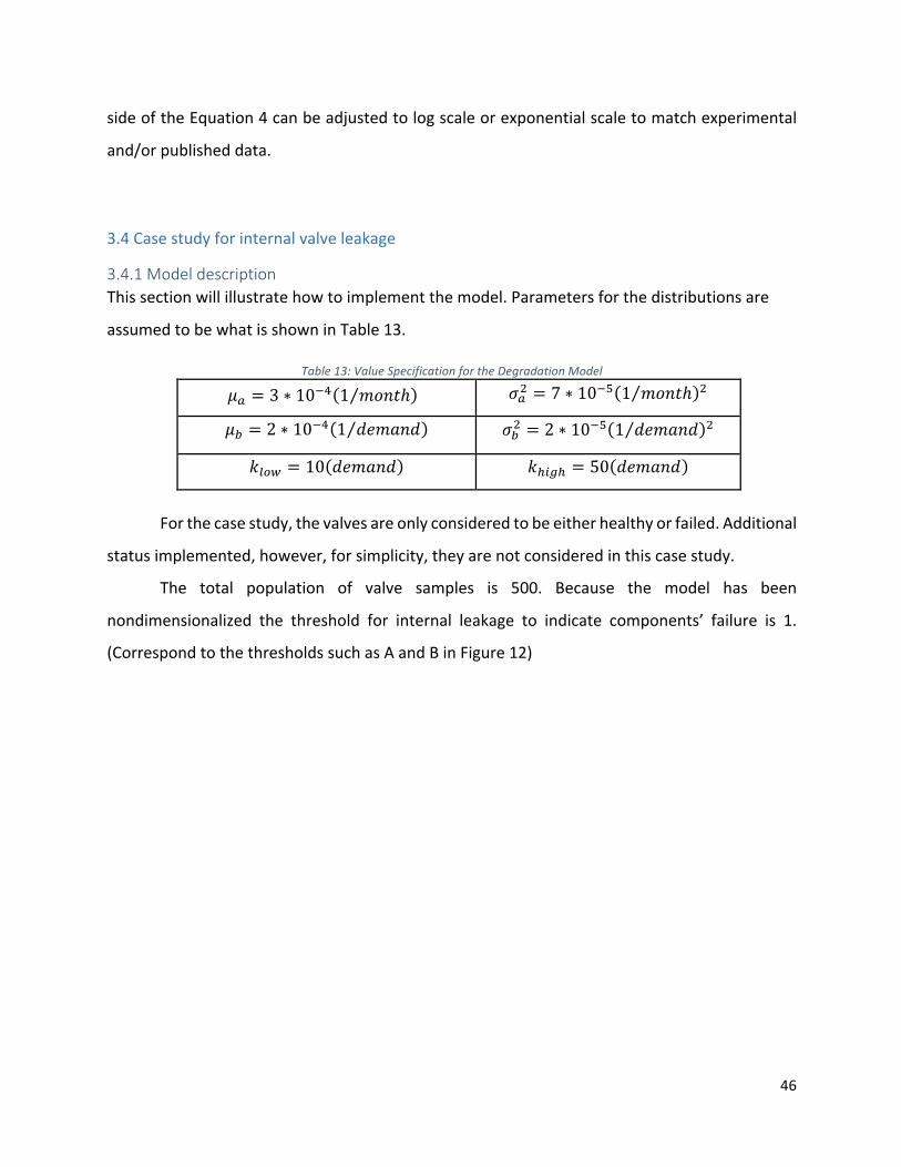
!
!
46!
!
side!of!the!Equation!4!can!be!adjusted!to!log!scale!or!exponential!scale!to!match!experimental!
and/or!published!data.!!
!
3.4!Case!study!for!internal!valve!leakage!!
3.4.1%Model%description%%This!section!will!illustrate!how!to!implement!the!model.!Parameters!for!the!distributions!are!
assumed!to!be!what!is!shown!in!Table!13.!!!
Table&13:&Value&Specification&for&the&Degradation&Model&
pQ = 3 ∗ 10Vr 1 wIC&ℎ 11! sQ; = 7 ∗ 10Vz 1 wIC&ℎ ;!
p? = 2 ∗ 10Vr 1 ,Uw=C, ! s?; = 2 ∗ 10Vz 1 ,Uw=C, ;!
Defg = 10 ,Uw=C, ! Dhijh = 50 ,Uw=C, !
!
! For!the!case!study,!the!valves!are!only!considered!to!be!either!healthy!or!failed.!Additional!
status!implemented,!however,!for!simplicity,!they!are!not!considered!in!this!case!study.!!!
! The! total! population! of! valve! samples! is! 500.! Because! the! model! has! been!
nondimensionalized! the! threshold! for! internal! leakage! to! indicate! components’! failure! is! 1.!
(Correspond!to!the!thresholds!such!as!A!and!B!in!Figure!12)!
!
!
!
!
!

!
!
47!
!
3.4.2%Simulation%results%%! The!Monte!Carlo!simulation!result!is!shown!in!Figure!13.!
!
Figure&13&Leakage&Degradation&Simulation&for&500&Samples&! As! shown!above!once! the! actual! degradation!exceeds! the! threshold! the! status!of! the!
component!would!be!defined!as!failed.!The!estimated!degradation!value!(blue!line!in!Figure!13),!
is!where=1and1N1are!the!mean!value!calculated!using!the!maximum!likelihood!method!to!fit!the!
500!samples,!and!D!is!the!mean!of!the!maximum!and!minimum!observation.!
!
Figure&14&Probability&of&Failure&
0 20 40 60 80 100 120 140 160 1800
0.5
1
1.5
2
Time [Year]
Leak
age
Rat
e500 Samples Monte Carlo Simulation
ExtremeVarianceThresholdMaximum Likelihood
0 50 100 150 2000
0.2
0.4
0.6
0.8
1Probability of failure
Time [Year]
Prob
abilit
y

!
!
48!
!
! !
! Figure!14!indicates!that!before!80!years!it!is!rare!for!components!to!fail!due!to!leakage.!
The!probability!starts!to!increase!at!around!80!years!and!after!operation!of!about!150!years,!the!
probability! for!the!component!to!fail! is!near!1.!This! indicates!that!almost!no!components!can!
withstand!the!degradation!and!still!be!functional!after!150!years.!
!
3.4.3%Results%discussion%%! Since!L!is!a!mixed!distribution,!it!is!desirable!to!learn!the!characteristics!of!the!distribution!
based!on!simulation!results.!Examining!the!difference!between!mean!and!median!is!an!approach!
that!can!be!used!to!study!the!symmetry!properties!of!a!distribution.!!
!
&&&&&&&&&&&&&&&Figure&15(a)&Mean&and&Median&for&Degradation&& & Figure&15(b)&Percent&difference&between&Mean&and&Median&! !
! Figure!15!indicates!that!the!mixed!distribution!for!L!is!nearly!but!not!entirely!symmetric!
since!the!mean!and!median!value!are!close!(b),!but!with!a!slightly!difference.!It!also!indicates!that!
the!mean!and!median!increase!linearly!with!time.!!
0 50 100 150 2000
0.2
0.4
0.6
0.8
1
1.2
1.4
1.6
1.8
Time [Year]
Leak
age
Rat
e
Mean for LMedian for L
0 50 100 150
-1.5
-1
-0.5
0
0.5
Time [Year]
Perc
ent(%
)(Median-Mean)/Median

!
!
49!
!
!
Figure&16&Variance&for&the&Degradation&! Figure! 16! indicates! that,! unlike! mean! and! median,! the! variance! of! the! degradation!
increases!nonlinearly!with!time.!
! Figure!17!presents! the!probability!distributions!of! the! leakage!rate!at!5!evenly!spaced!
time!intervals!within!the!simulation!time.!!
!
!
0 20 40 60 80 100 120 140 160 1800
0.005
0.01
0.015
0.02
0.025
0.03
0.035
Time [Year]
Leak
age
Rat
eVariance for the Leakage Rate
Variance for L,analyticalVariance for L, Monte Carlo

!
!
50!
!
!
Figure&17&Distribution&for&Leakage&Rate&at&Each&Given&Time&! !
! As!can!been!seen!from!the!figure!above,!the!distribution’s!deviation!increases!with!time.!!
! To!investigate!how!the!leakage!rate!distribution!would!fit!some!common!distributions,!
tests!of!fit!were!performed!using!16!candidate!distribution!models.!The!top!3!fitting!results!are!
shown!in!Table!14.!Detailed!fitting!results!are!shown!in!Appendix.!
!
!
!
!
!
!
!
0 0.5 1 1.5 20
0.005
0.01
0.015
0.02
0.025
0.03
0.035
Leakage Rate
Prob
abilit
y
Distribution for Leakage Rate at Each Given Time
Year 34Year 68Year 102Year 136Year 170

!
!
51!
!
&Table&14&Test&of&Fit&at&5&Selected&Times&
! Distribution!Type!! AD!! P!
Year!34!
Normal! 0.113! 0.992!
3!parameter!Weibull! 0.221! >0.500!
Gamma!!!!!!!!!!!!!!!!!!! 0.337! >0.250!
Year!68!!!
Normal! 0.136! 0.978!
Lognormal! 0.584! 0.128!
Gamma!!!!!!!!!!!!!!!!!!! 0.291! >0.250!
Year!102!
Normal! 0.237! 0.786!
Gamma!!!!!! 0.500! 0.222!
Logistic!!!!!!!!!!!!!!!!!!! 0.492! 0.177!
Year!136!
Normal! 0.174! 0.927!
3!parameter!Weibull! 0.305! >0.500!
Gamma!!!!!!!!!!!!!!!!!!! 0.309! >0.250!
Year!170!!!
Normal! 0.187! 0.904!
3!parameter!Weibull! 0.323! 0.471!
Gamma!!!!!!!!!!!!!!!!!!! 0.263! >0.250!
!
! In!the!tests!of!fit!run!by!Minitab,!a!lower!AndersonHDarling!(AD)!value!suggests!that!the!
data!fits!the!distribution!better,!and!higher!P!valve!suggests!that!the!null!hypothesis!is!not!
rejected.!The!null!hypothesis!is!that!the!data!follows!the!specified!distribution.!If!the!AD!value!
exceeds!the!given!cricical!value!shown!in!Table!15![16],!the!null!hypothesis!is!rejected!with!
certain!significance!levels.!If!the!P!value!is!great!than!0.05,!then!we!can!conclude!that!there!is!
little!or!no!evidence!to!reject!the!null!hypothesis.!
!

!
!
52!
!
!
!
Table&15&Critical&Value&for&Anderson-Darling&Test&(Mean&and&Median&Unknown)&!
! !
! !
!
! From!Table!14!and!Table!15,!normal!distribution!can!represnet!the!data!proporaly.!The!
null!hypothesis!is!not!rejected.!!
! It!is!also!desired!to!investigate!what!the!distribution!of!the!time!to!failure!would!be!for!
components!in!the!sample!data.!The!tests!of!fit!results!are!shown!is!Table!16!and!Figure!18.!The!
critical!value!for!AndersonHDarling!test!are!shown!in!Table!15.!!
Table&16&Test&of&Fit&for&the&Time&to&Failure&
Distribution!Type!! AD!! P!
Lognormal!!!!!!!!!!!!!!!!!!! 0681! 0075!
Loglogistic!!!!!!!!!!!!!!!!! 0.707! 0.039!
3Hparameter!Lognormal!!!!!!!!!!!!!!!!!!! 0.239! *!
3Hparameter!gamma!!!!!!!!!!! 0.260! *!
Note:!*!indicates!the!P!value!for!the!3Hparameter!distribution!cannot!be!calculated.!!
! As!can!be!seen!from!Table!16,!the!time!to!failure!data!can!be!represented!by!a!3!
parameter!gamma,!a!3Hparameter!Weibulll,!or!a!lognormal!distribution.!!
! As!can!be!seen!Figure18,!the!3Hparameter!distributions!fit!the!data!better.!However,!the!
industry!standard!does!not!use!a!3Hparameter!distribution!model!in!their!databases!due!to!the!
complexicity![17].!Thus,!a!two!parameter!lognormal!distribution!can!be!assumed!for!the!time!to!
failure! for! valves.! In! the! component! reliability! database,! a! gamma! distribution! is! used! to!
represent!the!time!to!failure!due!to!internal!leakage!for!valves!in!general.![18].!To!!better!match!
industry!databases!in!future!work,!the!model!needs!to!be!modified!accordingly.!!
!
! !!!!!!!!!!!!Significance!level!
Distribution! 10%! 5%! 2.50%! 1%!
Critical!
Value!
Normal!! 0.656! 0.787! 0.918! 1.092!Lognormal! 0.656 0.787 0.918 1.092 Gamma!!! 0.631 0.752 0.873 1.035 Weibull! 0.637 0.757 0.877 1.038

!
!
53!
!
16012080
99.999
90
50
10
10.1
T ime%[Year]
Percent
1501209060
99.9
99
90
50
10
1
0.1
T ime%[Year]
Percent
10050
99.999
90
50
10
10.1
T ime%[Year]
Percent
10010
99.99
9990
50
10
1
T ime%[Year]
Percent
3*Parameter1LognormalAD1=10.2391P*V alue1=1*
3*Parameter1GammaAD1=10.2601P*V alue1=1*
Goodness1of1F it1Test
LognormalAD1=10.6811P*V alue1=10.075
LoglogisticA D1=10.7071P*V alue1=10.039
Distribution%Fit%for%Time%to%FailureLognormal1*195%1C I Loglogistic1*195%1C I
3*Parameter1Lognormal1*195%1C I 3*Parameter1Gamma1*195%1C I
!
Figure&18&Distribution&Fit&for&Time&to&Failure&
!
Figure&19&Lognormal&Fit&for&Time&to&Failure&! Figure!19!shows!the!lognormal!fit!for!the!time!to!failure!data.!It!should!be!noted!that!unlike!the!
leakage!rate!at!a!given!time.!The!time!to!failure!is!not!a!symmetrical!distribution.!!
80 90 100 110 120 130 140 1500
0.005
0.01
0.015
0.02
0.025
0.03
0.035
Time [Year]
Prob
abilit
y
Time to FailureLognormal Fit

!
!
54!
!
!
Figure&20&&Lognormal&Distribution&Fit&for&the&Sample&Reliability&Function&!
! As! can! be! seen! from! Figure! 20,! the! lognormal! distribution! fits! the! reliability! function!
constructed! by! the! time! to! failure! data! well.! ! However,! it! should! be! noted! that! due! to! the!
relatively!small!population!used!for!the!Monte!Carlo!simulation,!the!fit!results!could!vary.!
! The! time!to! failure!determined!by! the!model!discussed! in! this!chapter!can!be!used!to!
specify!the!time!units!used!to!describe!a!component!transition!time!between!different!modes!as!
was! discussed! in! Chapter! 2.! For! example,! it! can! determine! how! long! it! takes! for! a! valve! to!
transition! from! a! ‘’nominal’’! mode! to! a! ‘’internal! leakage’’! mode.! It! can! also! determine! the!
transition!time!between!different!faulty!modes!such!as!‘’internal!leakage’’!and!‘’internal!rupture’’.! !
80 90 100 110 120 130 140 1500
0.1
0.2
0.3
0.4
0.5
0.6
0.7
0.8
0.9
1
Time [Year]
Rel
iabi
litySample ReliabilityLognormal Fit95% confidence bounds

!
!
55!
!
Chapter%4%Conclusion%and%Future%Work%%!
! In! this! thesis,! Chapter! 2! discussed! FFIP,! a! high! level! fault! propagation! method! for!
hardware!components!which!describes!the!system’s!behaviors!caused!by!certain!types!of!failure!
modes.! FFIP! helps! engineers! in! the! conceptual! design! stage! to! identify! function! loss! in! the!
designed!system,!and!locate!when!the!loss!occurs.!Behavioral!rules!and!functional!failure!logic!
for!components!of!interest!in!a!turbine!bypass!system!in!the!secondary!loop!in!a!nuclear!power!
plant! in!a!nuclear!hybrid!energy!system!are!developed.!The!method! is!demonstrated!through!
injection!of!a!failure!mode,!an!internal!leakage,!in!the!high!pressure!turbine!bypass!valve.!Results!
show!the!failure!mode!can!eventually!cause!the!entire!system!to!lose!its!functionality.!Chapter!3!
discussed!a!degradation!model!that!combines!the!effect!of!natural!aging!and!demand!frequency.!
The! degradation!model! is! combined!with! the! stressHstrength! interference!model! to! evaluate!
when!components!would!fail!due!to!a!particular!failure!mode.!!A!case!study!for!valve!leakage!is!
demonstrated!using!the!model.!TestsHofHfit!showed!that!the!model!needs!to!be!further!modified!
to!match!the!distributions!found!in!industry!standard!databases!to!enable!future!research.!!
! To!provide!a!more!accurate!representation!of!the!system,!potential!future!work!includes!
the!following:!the!high!level!fault!propagation!analysis!can!be!updated!to!include!software!faults!
and!human!error!as!well.!Combining!hardware!faults,!software!faults,!and!human!errors!can!help!
the! designer! develop! a! clearer! vision! of! the! proposed! system! design! and! determine! if!
redundancies! are! necessary! to! make! the! designed! system! more! robust.! For! the! low! level!
degradation!model,!the!turbine!bypass!line!demand!could!be!modeled!based!on!the!estimated!
availability! of! renewable! energy.! This! could! help! model! the! degradation! effects! of! the!
components!more!accurately.!!
!
!

!
!
56!
!
References!!
!
[1]!U.S.! Energy! Information!Administration! H! EIA! H! Independent! Statistics! and!Analysis.! (n.d.).!
Retrieved!April!19,!2016,!from!https://www.eia.gov/tools/faqs/faq.cfm?id=427!
[2]!Ela!E,!Milligan!M,!Kirby!B.!Operating!reserves!and!variable!generation,!NREL/!TPH5500H51978,!
National!Renewable!Energy!Laboratory,!Golden,!CO.!
[3]!Ruth,!M.!F.,!Zinaman,!O.!R.,!Antkowiak,!M.,!Boardman,!R.!D.,!Cherry,!R.!S.,!&!Bazilian,!M.!D.!
(2014).!NuclearHrenewable!hybrid!energy!systems:!Opportunities,!interconnections,!and!needs.!
Energy!Conversion!and!Management,!78,!684H694.!doi:10.1016/j.enconman.2013.11.030!
[4]!Garcia,!H.!E.,!Mohanty,!A.,!Lin,!W.,!&!Cherry,!R.!S.!(2013).!Dynamic!analysis!of!hybrid!energy!
systems! under! flexible! operation! and! variable! renewable! generation! –! Part! I:! Dynamic!
performance!analysis.!Energy,!52,!1H16.!doi:10.1016/j.energy.2013.01.022!
[5]!Ramakumar,!R.!Engineering!Reliability:!Fundamentals!and!Applications.!Englewood!Cliffs,!NJ:!
Prentice!Hall,!1993.!Print.!
[6]!O'Connor,!Patrick!D.!T.!Practical!Reliability!Engineering.!Chichester:!Wiley,!1985.!Print!
[7]! A! Brief! History! of! Nuclear! Power! in! the! U.S.! (2012).! Retrieved! April! 19,! 2016,! from!
https://nuclear.dukeHenergy.com/2012/07/31/aHbriefHhistoryHofHnuclearHpowerHinHtheHuHs/!!
[8]!Mutha,!C.,!Jensen,!D.,!Tumer,!I.,!&!Smidts,!C.!(2013).!An!integrated!multidomain!functional!
failure! and! propagation! analysis! approach! for! safe! system! design.! Artificial! Intelligence! for!
Engineering! Design,! Analysis! and! Manufacturing! AIEDAM,! 27(04),! 317H347.!
doi:10.1017/s0890060413000152!
[10]! Rosemount! Compact! Orifice! Flowmeters.! (n.d.).! Retrieved! April! 19,! 2016,! from!
http://www2.emersonprocess.com/enHus/brands/rosemount/flow/dpHflowHproducts/compactH
orificeHflowmeters/pages/index.aspx!

!
!
57!
!
[11]! Leak! detection.! (n.d.).! Retrieved! April! 19,! 2016,! from!
https://en.wikipedia.org/wiki/Leak_detection!
[12]!Dahlheimer,!J.!A.,!&!Testa,!D.!(1984).!The!Westinghouse!pressurized!water!reactor!nuclear!
power!plant.!Pittsburgh,!PA:!Westinghouse!Electric,!Water!Reactor!Division.!
[13]! Turbine! Bypass! Systems! H! DirectIndustry.! (n.d.).! Retrieved! April! 19,! 2016,! from!
http://pdf.directindustry.com/pdf/copesHvulcan/turbineHbypassHsystems/34699H15031.html!!
[14]!Strutt,!J.!E.,!Allsopp,!K.!and!Ouchet,!L.!(1995),!Reliability!prediction!of!pipes!and!valves.!Qual.!
Reliab.!Engng.!Int.,!11:!91–100.!doi:!10.1002/qre.4680110204!!
[15]!Atwood,!C.!L.!(2003).!Handbook!of!parameter!estimation!for!probabilistic!risk!assessment.!
Washington,!DC:!Division!of!Risk!Analyis!and!Applications,!Office!of!Nuclear!Regulatory!Research,!
U.S.!Nuclear!Regulatory!Commission.!!
[16]!Stephens,!M.!A.!(1974).!EDF!Statistics!for!Goodness!of!Fit!and!Some!Comparisons.!Journal!of!
the!American!Statistical!Association,!69(347),!730H737.!doi:10.1080/01621459.1974.10480196!
[17]!Component!Reliability!Data!Sheets!Update!2010!Table!of!...!(n.d.).!Retrieved!April!19,!2016,!
from!
http://nrcoe.inl.gov/resultsdb/publicdocs/AvgPerf/ComponentReliabilityDataSheets2010.pdf!
[18]! IndustryHAverage! Performance! for! Components! and! Initiating! Events! at!U.S.! Commercial!
Nuclear! Power! Plants! (NUREG/CRH6928).! (n.d.).! Retrieved! April! 19,! 2016,! from!
http://www.nrc.gov/readingHrm/docHcollections/nuregs/contract/cr6928/!

!
!
58!
!
Appendix%
0.40.30.2
99.999
90
50
10
10.1
Leakage&Rate
Percent
0.10.01
99.99
9050
10
1
Leakage&Rate
Percent
0.40.30.2
99.999
90
50
10
1
0.1
Leakage&Rate
Percent
0.50.40.30.2
99.999
90
50
10
10.1
Leakage&Rate
Percent
GammaAD.=.0.337.P2V alue.>.0.250
LognormalAD.=.0.664.P2V alue.=.0.082
Goodness.of.F it.Test
NormalAD.=.0.113.P2V alue.=.0.992
32Parameter.WeibullA D.=.0.221.P2V alue.>.0.500
Probability&Plot&for&the&34&YearNormal.2.95%.C I 32Parameter.Weibull.2.95%.C I
Gamma.2.95%.C I Lognormal.2.95%.C I
!
Figure&21&Distribution&Fit&at&the&1st&Selected&Time&
0.80.60.4
99.999
90
50
10
10.1
Leakage&Rate
Percent
10.10.01
99.99
9050
10
1
Leakage&Rate
Percent
0.80.60.4
99.999
90
50
10
1
0.1
Leakage&Rate
Percent
10.80.60.4
99.999
90
50
10
10.1
Leakage&Rate
Percent
GammaAD.=.0.291.P2V alue.>.0.250
LognormalAD.=.0.584.P2V alue.=.0.128
Goodness.of.F it.Test
NormalAD.=.0.136.P2V alue.=.0.978
32Parameter.WeibullA D.=.0.376.P2V alue.=.0.355
Probability&Plot&for&the&68&YearNormal.2.95%.C I 32Parameter.Weibull.2.95%.C I
Gamma.2.95%.C I Lognormal.2.95%.C I
!
Figure&22&Distribution&Fit&at&the&2nd&Selected&Time&

!
!
59!
!
1.21.00.80.6
99.999
90
50
10
10.1
Leakage&Rate
Percent
1.251.000.750.50
99.9
99
90
50
10
1
0.1
Leakage&Rate
Percent
1.41.210.8
99.999
90
50
10
1
0.1
Leakage&Rate
Percent
1.41.210.8
99.999
90
50
10
10.1
Leakage&Rate
Percent
GammaAD0=00.5000P3V alue0=00.222
LognormalAD0=00.8390P3V alue0=00.030
Goodness0of0F it0Test
NormalAD0=00.2370P3V alue0=00.786
LogisticAD0=00.4920P3V alue0=00.177
Probability&Plot&for&the&102&YearNormal03095%0C I Logistic03095%0C I
Gamma03095%0C I Lognormal03095%0C I
!
Figure&23&Distribution&Fit&at&the&3rd&Selected&Time&!
1.751.501.251.00
99.999
90
50
10
10.1
Leakage&Rate
Percent
10.1
99.99
9050
10
1
Leakage&Rate
Percent
1.751.51.251
99.999
90
50
10
1
0.1
Leakage&Rate
Percent
1.751.51.251
99.999
90
50
10
10.1
Leakage&Rate
Percent
GammaAD-=-0.309-P1V alue->-0.250
LognormalAD-=-0.572-P1V alue-=-0.137
Goodness-of-F it-Test
NormalAD-=-0.174-P1V alue-=-0.927
31Parameter-WeibullA D-=-0.305-P1V alue->-0.500
Probability&Plot&for&the&136&YearNormal-1-95%-C I 31Parameter-Weibull-1-95%-C I
Gamma-1-95%-C I Lognormal-1-95%-C I
!Figure&24&Distribution&Fit&at&the&4th&Selected&Time&

!
!
60!
!
2.01.51.0
99.999
90
50
10
10.1
Leakage&Rate
Percent
10.1
99.99
9050
10
1
Leakage&Rate
Percent
21.51
99.999
90
50
10
1
0.1
Leakage&Rate
Percent
2.521.51
99.999
90
50
10
10.1
Leakage&Rate
Percent
GammaAD,=,0.263,P1V alue,>,0.250
LognormalAD,=,0.489,P1V alue,=,0.221
Goodness,of,F it,Test
NormalAD,=,0.187,P1V alue,=,0.904
31Parameter,WeibullA D,=,0.323,P1V alue,=,0.471
Probability&Plot&for&the&170&YearNormal,1,95%,C I 31Parameter,Weibull,1,95%,C I
Gamma,1,95%,C I Lognormal,1,95%,C I
!
Figure&25&Distribution&Fit&at&the&5th&Selected&Time&