Embed Size (px)
Citation preview

OWNER'S MANUAL
KOHLERB AEGIS" 22,25 HP LIQUID=cOOLED
HORIZONTAL CRANKSHAFT
60- Iy, RUN'"
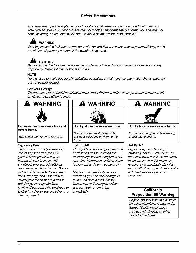
Safety Precautions
To insure safe operations please read the following statements and understand their meaning. Also refer to your equipment owner's manual for other important safety information. This manual contains safety precautions which are explained below. Please read carefully.
a WARNING Warning is used to indicate the presence of a hazard that can cause severe personal injuty, death, or substantial property damage if the warning is ignored.
a CAUTION Caution is used to indicate the presence of a hazard that wii/or can cause mihorpersonal injuty or property damage if the caution is ignored.
NOTE Note is used to notify people of installation, operation, or maintenance information that is important but not hazard-related.
For Your Safety! Tbese precaufions sbou/d be fo/o wed af a// fihes, Faiure fo fo/ow fbese precaufions could resu/f in injuu/y fo yourself and ofbers,
a WARNING
- Explosive Fuel can cause fires and severe burns.
Stop engine before filling fuel tank,
a WARNING
Hot liquid can cause severe burns.
Do not loosen radiator cap while engine is operating or warm to the touch.
Explosive Fuel! Gasohne is exfremek flammab/e andifs vapors can explode if ignifed Sfore gasohne on& in approved con fainers, in we// ven fiia fed unoccupied buiidngs, a way from sparks or flames. Do nof fi// fbe fue/ fank wbiie fbe engine is bo f or running since spii/ed fuel could ignife if if comes in confacf wifb bof pan's or sparks from ignifion, Do nof sfan' fbe engine near spi//ed fuel Never use gasohne as a cleaning agent
Hot Liquid! Tbe kquid coo/anf can ge f eMreme& bof from operafion, Turning fbe radafor cap wben fbe engine is bof can a//ow sfeam and sca/dng kquid fo blow ouf andburn you severe4
Sbuf off macbine. On& remove radafor cap wben coo/ enougb fo foucb wifb bare bands, S/ow& loosen cap fo ksf sfop fo rekeve pressure before remowng comp/efe&
Hot Parts can cause severe burns.
Do not touch engine while operating or just after stopping.
Hot Parts! €ngine componenfs can gef eMreme& bof from opera fion. To prevenf severe burns, do nof foucb fbese areas wbiie fbe engine is runninpr ihmedafe& affer if is furned off Never operafe fbe engine wifb beaf sbie/ds or guards removed
California Proposition 65 Warning
Engine exbausf from ibis producf confains cbemica/s known fo fbe Sfafe of Cakfornia fo cause cancec bin'b defecfs, or ofber rewroducfive barm,
2

Safety Precautions (Con t .) b . I AWARNING I I AWARNING I I I
Accidental Starts can cause severe injury or death.
Carbon Monoxide can cause severe nausea, fainting or death.
I Do not operate engine in closed or I leads before servicing. I I confined area. Disconnect and ground spark plug
Accidental Starts! Disabling engine. Accidental starting can cause severe injury or death, Before working on fbe engine or equipmen4 disable fbe engine as fo//ows: I) Disconnecf fbe sparkp/ug /ead(s). 2) Disconnecf negafive p) baffety cable from baffety
Lethal Exhaust Gases! Engine exbausf gases confain poisonous carbon monoxidee. Carbon monoxide is odorless, co/odess, and can cause deafb if inba/ea! A void inbahng exbausf fumes, andneverrun fbe engine in a closed bui/&ng or confined area,
A CAUTION
Electrical Shock can cause injury.
Do not touch wires while engine is running.
A WARNING
Rotating Parts can cause severe injury.
Stay away while engine is in opera tion.
Electrical Shock! Rotating Parts! Never foucb e/ecfrica/ wires or componenfs wbiie fbe engine is running. Tbey can be sources of e/ecfnca/ sbock
Keep bands, fee4 ha/$ and c/ofbing away from a//mowngparfs fo prevenf injuty Never operafe fbe engine wifb covers, sbrouds, or guards removed
I AWARNING I
severe acid burns. Charge batte y only in a well ventilated area. Keep sources of ianition a wav.
Explosive Gas! Bafferies produce exp/osive hydrogen gas wbiie being cbarged 7Z prevenf a fire or exp/osion, cbarge ba fferies on4 in we// venfiiafed areas, Keep sparks, open flames, and ofber sources of ignifion a way from fbe ba ffety a f a// fihes, Keep bafferies ouf of fbe reach of cbi/dren, Remove a/!jewe/ty wben servicing ba fferies
Before dsconnecfing fbe negafive (-) ground cable, make sure a// swifcbes are OFF /f ON; a spark wii! occur af fbe ground cable fermina/ wbicb cou/d cause an exp/osion if hydrogen gas orgasohne vapors are present
Congratulations - You have selected a fine four-cycle, twin cylinder, liquid-cooled engine. Kohler designs long life strength and on-the-job durability into each engine ... making a Kohler engine dependable ... dependability you can count on. Here are some reasons why:
Efficient overhead valve design, and pressure lubrication provide maximum power, torque, and reliability under all operating conditions.
Dependable, maintenance free electronic ignition ensures fast, easy starts time after time.
Kohler engines are easy to service. All routine service areas (like the dipstick and oil fill, air cleaner, spark plugs, and carburetor) are easily and quickly accessible.
Parts subject to the most wear and tear (like the cylinder liner and camshaft) are made from precision formulated cast iron.
Every Kohler engine is backed by a worldwide network of over 70,000 distributors and dealers. Service support is just a phone call away. Call 1-800-544-2444 (US. & Canada) for Sales & Service assistance.
To keep your engine in top operating condition, follow the maintenance procedures in this manual.
3

--,Heavy-Duty Air Clean
nil \ Radiator
Oil Drain
ler
#tick
I Figure 1. Typical KohleP Aegis'" Horizontal Shaft Engine.
Oil Recommendations Using the proper type and weight of oil in the crankcase is extremely important. So is checking oil daily and changing oil regularly. Failure to use the correct oil, or using dirty oil, causes premature engine wear and failure.
Oil Type Use high quality detergent oil of API (American Petroleum Institute) service class SGg SH, SJ or higher. Synthetic oils may be used. Select the viscosity based on the air temperature at the time of operation as shown in the following table.
IRECOMMENDED S A E VISCOSITY GRADES I
,I I 1 I I I I I I I ! ! I I
4b I I 0~130 -20 - i o 0 1'0 20
TEMPERATURE RANGE EXPECTED BEFORE NEXT OIL CHANGE II *Use of synthetic oil having 5W-20 or 5W-30 rating is acceptable, up to 4 "C (40°F). **Synthetic oils will provide better starting in extreme cold below -23°C (-10°F).
Figure 2. Viscosity Grades Table.
NOTE: Using other than service class SG, SH, SJ or higher oil or extending oil change intervals longer than recommended can cause engine damage.
A logo or symbol on oil containers identifies the API service class and SAE viscosity grade. See Figure 3.
W Figure 3. Oil Container Logo.
Refer to "Maintenance Instructions" beginning on page 8 for detailed oil check, oil change, and oil filter change procedures.
Fuel Recommendations
a WARNING: Explosive Fuel! Gasokne is exfremek flammable and ifs vapors can explode if @nifed Sfore gasokne on& in approved con fainers, in we// ven fih fed unoccupied buildngs, a way from sparks or flames. Do nof fi7l fhe fuel fank whi7e fhe engine is ho f or running since spi//ed fue/ could ignife if if comes in confacf wifh hof pan's or sparks from @nifion. Do nof sfan' fhe engine near spilled fuel Never use gasokne as a cleaning agent
General Recommendations Purchase gasoline in small quantities and store in clean, approved containers. A container with a capacity of 2 gallons or less with a pouring spout is recommended. Such a container is easier to handle and helps eliminate spillage during refueling.
Do not use gasoline left over from the previous season, to minimize gum deposits in your fuel system and to insure easy starting.
Do not add oil to the gasoline. Do not overfill the fuel tank. Leave room for the fuel to expand.
4
Fuel Type For best results use only clean, fresh, unleaded gasoline with the pump sticker octane rating of 87 or higher. In countries using the Research method, it should be 90 octane minimum.
Unleaded gasoline is recommended as it leaves less combustion chamber deposits. Leaded gasoline may be used in areas where unleaded is not available and exhaust emissions are not regulated. Be aware however, that the cylinder heads may require more frequent service.
Gasoline/Alcohol blends Gasohol (up to 10% ethyl alcohol, 90% unleaded gasoline by volume) is approved as a fuel for Kohler engines. Other gasoline/alcohol blends are not approved.
Gasoline/Ether blends Methyl Tertiary Butyl Ether (MTBE) and unleaded gasoline blends (up to a maximum of 15% MTBE by volume) are approved as a fuel for Kohler engines. Other gasoline/ether blends are not approved.
Coolant Recommendations Use equal parts of ethylene glycol (anti-freeze) and water only. Distilled or deionized water is recommended, especially in areas where the water contains a high mineral content. Propylene glycol based anti-freeze is not recommended.
This mixture will provide protection from -37" C (-34 O F) to 108" C (226" F). For protection and use outside the indicated temperature limits, follow the anti-freeze manufacturers instructions on the container, but do not exceed 70% anti-freeze.
DO NOT use anti-freeze with stop-leak additive@), or put any other additives in the cooling system.
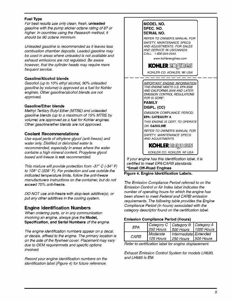
Engine Identification Numbers When ordering parts, or in any communication involving an engine, always give the Model, Specification, and Serial Numbers of the engine.
The engine identification numbers appear on a decal, or decals, affixed to the engine. The primary location is on the side of the flywheel cover. Placement may vary due to OEM requiremnets and specfic options involved.
Record your engine identification numbers on the identification label (Figure 4) for future reference.
MODEL NO. SPEC. NO. SERIAL NO. REFER TO OWNER'S MANUAL FOR SAFETY, MAINTENANCE SPECS AND ADJUSTMENTS. FOR SALES AND SERVICE IN US/CANADA
w. kohlerengines. corn CALL: 1-800-544-2444.
KOHLER CO. KOHLER, Wl USA
IMPORTANT ENGINE INFORMATION I THIS ENGINE MEETS U.S. EPA 2005 AND CALIFORNIA 2006 AND LATER EMISSION CONTROL REGULATIONS FOR SI SORE*.
FAMILY DISPL. (CC) EMISSION COMPLIANCE PERIOD: EPA: CATEGORY A THIS ENGINE IS CERT: TO OPERATE ON: GASOLINE
REFER TO OWNER'S MANUAL FOR SAFETY, MAINTENANCE SPECS AND ADJUSTMENTS.
I KOHLER CO. KOHLER. WI USA
If your engine has this identification label, it is certified to meet EPNCARB standards. *Small Off-Road Engines
Figure 4. Engine Identification Labels.
The Emission Compliance Period referred to on the Emission Control or Air Index label indicates the number of operating hours for which the engine has been shown to meet Federal and CAR9 emission requirements. The following table provides the Engine Compliance Period (in hours) associated with the category descriptor found on the certification label.
Emission Compliance Period (Hours)
Refer to certification label for engine displacement.
Exhaust Emission Control System for models LH630, and LH685 is EM.
5
Model Designation Model LH685 for example: L designates liquid cooled, H designates horizontal crankshaft, and 685 designates engine size or displacement in cubic centimeters. A letter suffix designates a specific version as follows:
Suffix Designates S Electric Start
Operating Instructions Ako read fbe operafhg insfrucfions of fbe equ@menf fbk engine powers,
Pre-Start Checklist Starting Check oil level. Add oil if low. Do not overfill.
Check coolant level. Add coolant if low.
Check fuel level. Add fuel if low.
Check cooling air intake areas and external surfaces of engine. Make sure they are clean and unobstructed.
Check that the air cleaner components and all shrouds, equipment covers, and guards are in place and securely fastened.
Check that any clutches or transmissions are disengaged or placed in neutral. This is especially important on equipment with hydrostatic drive. The shift lever must be exactly in neutral to prevent resistance which could keep the engine from starting.
a WARNING: Lethal Exhaust Gases! Engine exbausf gases confah poisonous carbon monoxide. Carbon monoxide is odorless, co/odess, and can cause dea fb if inhaea! A void hbahng exbausf fumes, and ne ver run fbe engine in a closed bui/&ng or confined area,
Cold Weather Starting Hints 1. The cooling system must be filled with coolant
capable of providing proper protection against freezing at the lowest temperature expected (see ”Coolant Recommendations” on page 5).
2. Be sure to use the proper oil for the temperature expected. See Figure 2 on page 4.
3. Declutch all possible external loads.
4. A warm battery has much more starting capacity than a cold battery
5. Use fresh winter grade fuel. NOTE: Winter grade gasoline has a higher volatility to improve starting. Do not use gasoline left over from summer.
1. Place the throttle control midway between the “slow” and “fast” positions. Place the choke control into the “on” position.
2. Start the engine by activating the key switch. Release the switch as soon as the engine starts.
NOTE: Do not crank the engine continuously for more than 10 seconds at a time. If the engine does not start, allow a 60 second cool down period between starting attempts. Failure to follow these guidelines can burn out the starter motor.
NOTE: Upon start up, a metallic ticking may occur. This is caused by hydraulic lifter leak down during storage. Run the engine for 5 minutes. The noise will normally cease in the first minute. If noise continues, run the engine at mid throttle for 20 minutes. If noise persists, take the engine to your local Kohler Service outlet.
If the starter does not turn the engine over, shut off starter immediately. Do not make further attempts to start the engine until the condition is corrected. Do not jump start using another battery (refer to “Battery” on page 7). See your Kohler Engine Service Dealer for trouble analysis.
3. For a Cold Engine - Gradually return the choke control to the “off” position after the engine starts and warms up.
The engine/equipment may be operated during the warm up period, but it may be necessary to leave the choke partially on until the engine warms up.
4. For a Warm Engine - Return choke to “off” position as soon as engine starts.
Stopping 1. Remove the load by disengaging all PTO
attachments.
2. Position the throttle control somewhere between half and full throttle; then stop the engine.
6
Battery A 12 volt battery is normally used. Refer to the operating instructions of the equipment this engine powers for specific battery requirements.
If the battery charge is not sufficient to crank the engine, recharge the battery (see page 15).
Operating
Angle of Operation This engine will operate continuously at angles up to 204 Check oil level to assure crankcase oil level is at the “FULL” mark on the dipstick.
Refer to the operating instructions of the equipment this engine powers. Because of equipment design or application, there may be more stringent restrictions regarding the angle of operation.
NOTE: Do not operate this engine continuously at angles exceeding 20” in any direction. Engine damage could result from insufficient lubrication.
Cooling NOTE: If debris builds up on the radiator, cooling
system, or other external areas, stop the engine immediately and clean. Operating the engine with blocked or dirty cooling system areas can cause extensive damage due to overheating. See ”Clean Air Intake/Cooling Area”, page 14.
High Temperature Sensor Some engines are equipped with a high temperature sensor mounted in the cooling system. If the safe operating temperature is exceeded, it will either shut off the engine or activate a warning signal, depending on the application.
If the warning light illuminates or engine kills indicating excessive operating temperatures:
1. Make sure all air intake and cooling surfaces are clean and free of debris.
2. After engine has sufficiently cooled, check the coolant level in system to make sure it is not low. See “Checking Coolant Level”, page 10.
3. Check the system for external leaks.
4. If the cause is none of the above or cannot be identified, contact an Authorized Kohler Engine Dealer for appropriate diagnosis and correction.
WARNING: Hot Parts! €ngine componenfs can gef exfreme4 bof from operafion, To prevenf severe burns, do nof foucb fbese areas wbi/e fbe enghe is running-or immedife/y afier if is furned off Never operafe fbe enghe wifb beaf shields or guards removed
Engine Speed NOTE: Do not tamper with the governor setting to
increase the maximum engine speed. Overspeed is hazardous and will void the engine warranty. The maximum allowable high idle speed for these engines is 3750 RPM.
7

Maintenance Instructions Maintenance, repair, or replacement of the emission control devices and systems, which are being done at the customers expense, may be performed by any non-road engine repair establishment or individual. Warranty repairs must be performed by an authorized Kohler service outlet.
a WARNING: Accidental Starts! Disabling engine, Accidental starting can cause severe injury or death, Before workfng on fbe engine or equipmen4 disable fbe engine as fo//ows: I) Disconnecf fbe sparkplug /ead(s). 2) Disconnecf negafive p) baffety cable from baffety
Daily or Before Starting Engine
Maintenance Schedule These required maintenance procedures should be performed at the frequency stated in the table. They should also be included as part of any seasonal tune-up.
Freauencv I Maintenance Reauired
Fill fuel tank. I Check oil level. Check coolant level. Check air cleaner for dirty', loose, or damaged parts. Check air intake screen, radiator, and cooling areas, clean as necessary'.
Annually or Every 200 Hours Every 250 Hours
Clean and check cooling areas. Redace fuel filter. Every 100 Hours I Change oil and oil filter (more frequently under severe conditions). Check spark plug condition and gap. Replace air cleaner element and check inner element'.
Annually or Every 500 Hours Every 2 Years or
Every 1000 Hours
Replace spark plugs.
Change engine coolant.
1. Make sure the engine is stopped, level, and is cool so the oil has had time to drain into the sump.
2. To keep dirt, debris, etc., out of the engine, clean the area around the dipstick before removing it.
3. Remove the dipstick; wipe oil off. Reinsert the dipstick into the tube and press all the way down. See Figure 5.
Figure 5. Checking Oil Level.
4. Pull the dipstick out and check the oil level.
The oil level should be up to, but not over, the "F" mark on the dipstick. See Figure 6.
8
I
12 050 OI-S 52 050 02-S
Operating Range
2- 1/2"
3-3/8"
I
"F" Mark
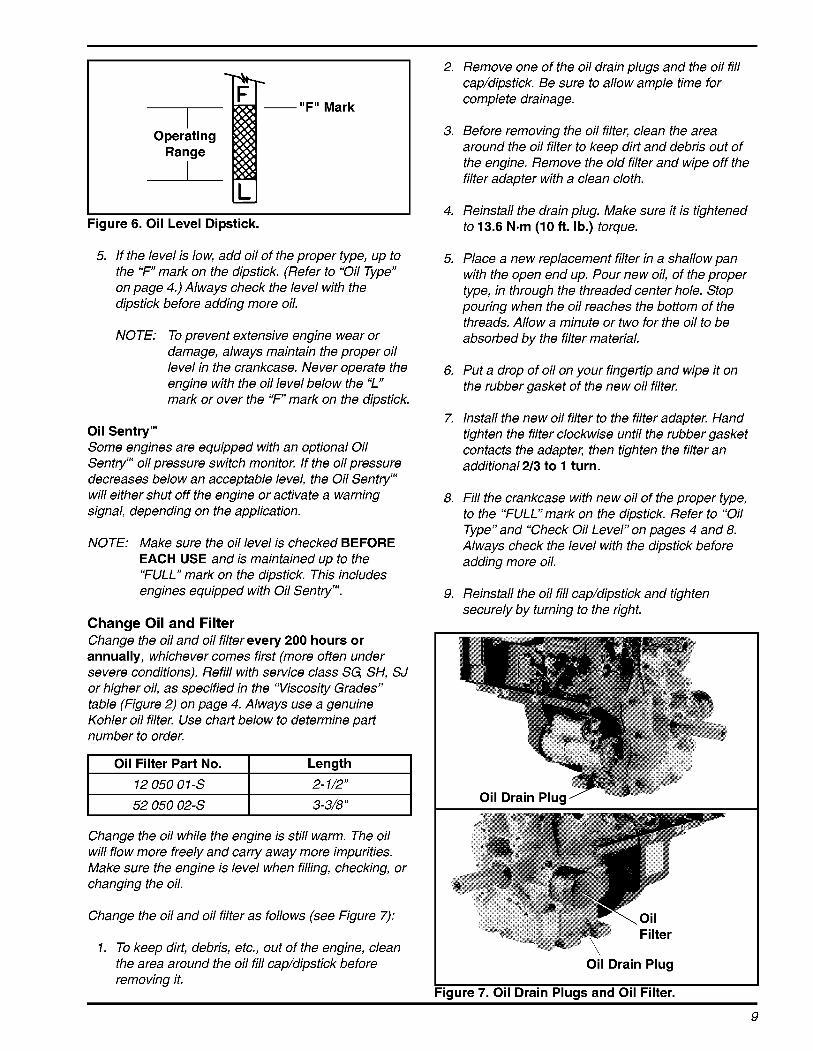
Figure 6. Oil Level Dipstick.
5. If the level is low, add oil of the proper type, up to the "F" mark on the dipstick. (Refer to "Oil Type" on page 4.) Always check the level with the dipstick before adding more oil.
NOTE: To prevent extensive engine wear or damage, always maintain the proper oil level in the crankcase. Never operate the engine with the oil level below the 'I" mark or over the "F" mark on the dipstick.
Oil Sentry'" Some engines are equipped with an optional Oil Sentry" oil pressure switch monitor. If the oil pressure decreases below an acceptable level, the Oil Sentry" will either shut off the engine or activate a warning signal, depending on the application.
NOTE: Make sure the oil level is checked BEFORE EACH USE and is maintained up to the "FULL" mark on the dipstick. This includes engines equipped with Oil Sentry".
Change Oil and Filter Change the oil and oil filter every 200 hours or annually, whichever comes first (more often under severe conditions). Refill with service class SG, SH, SJ or higher oil, as specified in the "Viscosity Grades" table (Figure 2) on page 4. Always use a genuine Kohler oil filter. Use chart below to determine part number to order.
I Oil Filter Part No. I Length I
Change the oil and oil filter as follows (see Figure 7):
1. To keep dirt, debris, etc., out of the engine, clean the area around the oil fill cap/dipstick before removing it.
2. Remove one of the oil drain plugs and the oil fill cap/dipstick. Be sure to allow ample time for complete drainage.
3. Before removing the oil filter, clean the area around the oil filter to keep dirt and debris out of the engine. Remove the old filter and wipe off the filter adapter with a clean cloth.
4. Reinstall the drain plug. Make sure it is tightened to 13.6 N-m (10 ft. Ib.) torque.
5. Place a new replacement filter in a shallow pan with the open end up. Pour new oil, of the proper type, in through the threaded center hole. Stop pouring when the oil reaches the bottom of the threads. Allow a minute or two for the oil to be absorbed by the filter material.
6. Put a drop of oil on your fingertip and wipe it on the rubber gasket of the new oil filter.
7. Install the new oil filter to the filter adapter. Hand tighten the filter clockwise until the rubber gasket contacts the adapter, then tighten the filter an additionala3 to 1 turn.
8. Fill the crankcase with new oil of the proper type, to the "FULL" mark on the dipstick. Refer to "Oil Type" and "Check Oil Level" on pages 4 and 8. Always check the level with the dipstick before adding more oil.
9. Reinstall the oil fill cap/dipstick and tighten securely by turning to the right.
Oil Drain Plug
'igure 7. Oil Drain Plugs and Oil Filter.
9

Cooling System Maintenance and Service Important service notes:
Do not operate the engine without coolant in the system.
Do not remove the radiator cap when hot. Engine coolant is hot and under pressure and can cause severe burns.
To prevent engine overheating and damage, use the recommended anti-freeze mixture in the cooling system.
To prevent engine damage, do not pour cold water into a hot engine.
To prevent engine damage, do not use anti-freeze with stop-leak additive@) or put other additives in the cooling systems.
Cooling system capacity is approximately 2 L (2.18 qt.).
Maintenance This engine is liquid-cooled, circulating a mixture of ethylene glycol and water for dependable operation. A pump is used to circulate the coolant through the system and radiator. A thermostat contained in the system assures automatic temperature control and rapid warm-up. Maintaining the correct coolant level and cleaning any debris accumulation from the inlet screen and radiator surfaces are critical to insuring long life, proper system performance, and preventing overheating. Check the coolant level in the overflow reservoir, and clean away any debris accumulation daily or before each use. At the same time, inspect the hoses and all connections for signs of leakage.
Servicing Engine coolant should be changed every 2 years or every 1000 hours, whichever comes first. When changing the engine coolant, the system should also be flushed to remove any contaminants left behind during draining. Following are recommended procedures for checking, draining, flushing, and filling the cooling system.
Figure 8. Overflow Reservoir Location.
1. Check the coolant level within the overflow reservoir. Coolant level should be between the ”FULL”and ‘YDD”marks on the reservoir. See Figure 9. Do not operate the engine with the coolant level below the ”ADD” mark.
Add coolant to the overflow reservoir as required. Use equal parts of ethylene glycol and water only (distilled or deionized water is recommended).
Figure 9. Coolant Levels on Reservoir.
Checking Coolant Level The coolant level should be checked at the overflow reservoir, located within the formed supports of the fan shroud. See Figure 8.
10

Draining Cooling System 1. Stop the engine and allow it to cool sufficiently
2. Check if the radiator is cool to the touch. Slowly loosen the radiator cap to the first stop and allow any pressure to bleed off. Then loosen it fully and remove it. Loosen radiator drain plug and allow coolant to drain. See Figure 10.
I
'igure 10. Removing Radiator Drain Plug.
3. Remove the coolant drain plugs located on each side of the engine block. See Figure 11. Drain the coolant into a suitable container. After the coolant has drained completely, apply pipe sealant with TeflorP (Loctite@ No. 592 or equivalent), to the threads and reinstall the plugs. Torque the two plugs to 13.5 N-m (120 in. Ib.).
'igure 11. Coolant Drain Plug (Oil Filter Side).
4. Remove overflow hose from reservoir. Unhook inboard retainer and slide reservoir out of supports. See Figure 12. Pour out the contents and wash or clean as required. Dispose of all the old coolant properly according to local regulations.
Figure 12.
5. Reinstall the reservoir cap. Do not kinwpinch the hose.
6. Flush the cooling system (see "Flushing Cooling System").
Flushing Cooling System With system properly drained:
1. Fill the cooling system with clean water and a cooling system cleaner recommended for aluminum engines. Follow the directions on the container.
2. Reinstall and tighten the radiator cap.
3. Start and run the engine for five minutes, or until it reaches operating temperature. Stop the engine and allow it to cool.
4. Drain the cooling system (Refer to "Draining Cooling Systems).
5. Fill the cooling system (see "Filling Cooling System").
Filling Cooling System 1. Check the condition of cooling system hoses,
clamps, and associated components. Replace as required.
2. Mix equal parts of ethylene glycol anti-freeze and distilled or deionized water (see "Coolant Recommendations" on page 5). For extremely cold temperature applications or protection outside the limits listed in the "Coolant Recommendations" Section, refer to the anti- freeze manufacturers instructions on the container, but do not exceed 70% anti-freeze.
11

3. Fill the cooling system through neck for radiator with the coolant mixture. Allow coolant to drain into the lower areas. Fill the overflow reservoir to a level between the ”FULL”and “ADD”marks. See Figure 9. Reinstall the radiator and reservoir caps.
4. Start and run the engine for five minutes. Stop the engine and allow to cool.
5. Recheck the coolant level in the reservoir. Coolant level should be between the ”FULL”and ‘YDD” marks. Add coolant to reservoir if required. See Figure 9.
Air Cleaner Element and Inner Element Service This engine is equipped with a heavy-duty high density paper air cleaner element surrounding a canister style inner element. Cleaning is not recommended, each element should be replaced when dim. See Figure 13.
Ygure 13. Air Cleaner Element and Inner Element.
The air cleaner system should be inspected daily or before starting the engine for a buildup of dirt and debris, or for any damaged, or loose components. Keep the system clean and properly secured. Replace any damaged air cleaner comments. Do not operate the engine without the complete air cleaner system installed and properly secured.
NOTE: Operating the engine with loose, damaged, or missing air intake components can allow unfiltered air into the engine, causing premature wear and failure.
To Service Every 250 hours of operation (more often under extremely dusty or dirty conditions), replace the paper element and check inner element. Follow these steps.
1. Unhook the two retaining clips and remove the end cap from the air cleaner housing. See Figure 14.
Figure 14. Removing End Cap.
2. Pull the air cleaner element out of the housing. See Figure 15.
I Figure 15. Removing Air Cleaner Element.
3. After the main element is removed, check the condition of the inner element. It should be replaced whenever it appears dim, typically every other time the main element is replaced. Clean the area around the base of the inner element before removing it, so dirt does not get into the engine. See Figure 16.
‘igure 16. Removing Inner Element.
12

4. Do not wash the paper element and inner element or use pressurized air, this will damaged the elements. Replace dim, bent, or damaged elements with new genuine Kohler elements as required. Handle new elements carefully; do not use if the sealing surfaces are bent or damaged.
5. Check all parts for wear, cracks, or damage. Replace any damaged components.
6. Install the new inner element, Kohler Part No. 25 083 04-S followed by the outer element, Kohler Part No. 25 083 01 -S. Slide each fully into place in the air cleaner housing.
7. Reinstall the end cap so the dust ejector valve is down and secure with the two retaining clips. See Figure 17.
Dust Ejector
Figure 17. Air Cleaner Assembly.
Air Intake System and Air Cleaner Components
Air Cleaner Housing/End Cap Assembly Make sure air cleaner housing including the dust ejector valve and the end cap is in good condition and not cracked. The two retainer clips should positively lock when cap is installed.
Air Cleaner Mounting Base Make sure the base is securely fastened to the upper valve cover screw locations and the screws securing the clamp bracket for the air cleaner housing are properly installed and tight.
Breather Tube Make sure the tube is in good condition and is properly secured to both the breather cover and elbow adapter.
Cooling Fan Assembly, Belt, and Drive Pulleys The cooling fan assembly, used to draw the air in and across the radiator, is attached to a hub and pulley assembly with sealed ball bearings. It is belt driven by a lower split pulley attached to the flywheel and requires very little service or maintenance. DO NOT operate the engine without the fan and cooling system functioning properly, or engine damage will occur. See Figure 18.
7gure 18. Cooling System Belt Drive (Cover Removed For Clarity).
1. Inspect the fan for any cracks, damaged/missing fan blades, and secure mounting.
2. The bearings, within the bearing carrier in the hub of the pulley, should rotate smoothly, without roughness, binding, or play/wobble.
Air Cleaner Hose Inspect the air cleaner hose to make sure it is not cracked, split or damaged. Check that the air cleaner hose is securely clamped to both the air cleaner outlet and the inlet elbow on the carburetor.
13

3. The v-groove of each pulley (upper and lower) should not be bent, nicked, or damaged. Pulley mounting areas and lower pulley shims should be free of any cracks or elongation. See Figure 19.
'igure 19. Pulley and Drive Belt.
4. The drive belt is designed and constructed for this application. Do not use a substitute belt. Check the overall condition of the belt. If belt is cracked, damaged, or adequate tension does not exist, have necessary servicing performed by an authorized Kohler Engine Service Dealer.
Clean Air Intake/Cooling Areas To insure proper air circulation and cooling, make sure the serviceable screen, radiator cooling fins, fan assembly and external surfaces of the engine are kept clean at all times.
Every 100 hours of operation (more often under extremely dusty, dirty conditions), thoroughly clean the radiator cooling fins, fan assembly, intake system and external surfaces of the engine. Make sure all parts are reinstalled before starting the engine.
Clean the cooling fins of the screen and radiator with a soft brush or blow out, using clean, compressed air. See Figure 20. Do not use a high pressure washer, to avoid damaging the cooling fins.
NOTE: Operating the engine with a restricted air intake screen or radiator, damagedhroken fan assembly, or missing fan shroud will cause engine damage due to overheating.
Figure 20. Clean Radiator Cooling Fins - and Screen.
14

Ignition System This engine is equipped with an electronic CD ignition system. Other than periodically checkingheplacing the spark plugs, no maintenance or adjustments are necessary or possible with this system.
In the event starting problems should occur, which are not corrected by replacing the spark plugs, see your Kohler Engine Service Dealer for trouble analysis.
Check Spark Plugs Annually or every 200 hours of operation (whichever comes first), remove the spark plugs, check condition, and reset the gap or replace with new plugs as necessary. Every 500 hours of operation replace the spark plugs. The standard spark plug is a Champion@ RC14YC (Kohler Part No. 66 132 01 4). Equivalent alternate brand plugs can also be used.
1. Before removing the spark plug, clean the area around the base of the plug to keep dirt and debris out of the engine.
2. Remove the plug and check its condition. Replace the plug if worn or reuse is questionable.
NOTE: Do not clean the spark plug in a machine using abrasive grit. Some grit could remain in the spark plug and enter the engine, causing extensive wear and damage.
3. Check the gap using a wire feeler gauge. Aqust the gap to 0.76 mm (0.030 in.) by carefully bending the ground electrode. See Figure 21.
4. Reinstall the spark plug into the cylinder head. Torque the spark plug to 24.4/29.8 N-m (18/22 ft. Ib.).
Ground Electrode 0.76 mm
(0.030 in.) Gap
'igure 21. Servicing Spark Plug.
Battery Charging
a WARNING: Explosive Gas! Bafferies produce exp/osive hydrogen gas wbi7e being charged To pre ven f a fire or exp/osion, cbarge ba fferies on4 in we// venfihfed areas. Keep sparks, open flames, and ofber sources of @nifion a way from fbe ba ffety af a// fihes. Keep bafferies ouf of fbe reach of cbi7dren Remove a//je we/ty when sewicing ba fferies
Before disconnecfing fbe nega five p) ground cable, make sure a// swifcbes are OFF /f 04 a spark wi7/ occur af fbe ground cable fermina/ wbicb cou/d cause an exp/osion if hydrogen gas orgasokne vapors are present
NOTE: Do not apply 12 volt DC to kill terminal of ignition module.
Fuel Filter Some engines are equipped with an in-line fuel filter. Periodically inspect the filter and replace when dirty. Use a genuine Kohler filter, part number 24 050 0 2 4 .
15

Carburetor Troubleshooting and Adjustments In compliance with the government emission standards, the carburetor is calibrated to deliver the correct fuel-to-air mixture to the engine under all operating conditions. The carburetor cannot be adjusted, except for low idle speed (RPM). Carburetor servicing is to be performed by an authorized Kohler Engine Service
Figure 22. Carburetor and Idle Speed Adjustment.
Troubleshooting If engine troubles are experienced that appear to be fuel system related, check the following areas before adjusting the carburetor.
Make sure the fuel tank is filled with clean, fresh gasoline.
Make sure the fuel tank cap vent is not blocked and that it is operating properly.
If the fuel tank is equipped with a shut-off valve, make sure it is open.
If the engine is equipped with an in-line fuel filter, make sure it is clean. Replace the filter if it is dirty or restricted.
Make sure fuel is reaching the carburetor. This includes checking the fuel lines and fuel pump for restrictions or faulty components, replace as necessary.
Make sure the air cleaner element and precleaner are clean and properly secured.
Make sure the air intake screen, blower housing, and cooling surfaces of radiator are clean and free of dirt and debris.
Make sure cooling system is filled to the proper level.
I t after checking the items listed above, the engine is hard to start, runs roughly, or stalls at low idle speed, it may be necessary to adjust or service the carburetor.
Adjust Carburetor Low idle speed (RPM) setting:
1. Place the throttle control into the “idle” or “slow” position. Set the low idle speed to 1200 RPM* (2 75 RPM) by turning the low idle speed adjusting screw (cable w/knob on some models) in or out. Check the speed using a tachometer.
*NOTE: The actual low idle speed depends on the application - refer to equipment manufacturers recommendations. The standard low idle speed is 1200 RPM.
2. If proper operation is not restored after adjusting the low idle speed, carburetor servicing by an authorized Kohler Engine Service Dealer may be required.
16
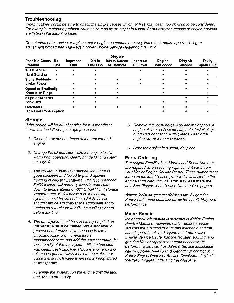
Troubleshooting When troubles occuk be sure to check the simple causes which, at first, may seem too obvious to be considered. For example, a starting problem could be caused by an empty fuel tank. Some common causes of engine troubles are listed in the following table.
Do not attempt to service or replace major engine components, or any items that require special timing or adjustment procedures. Have your Kohler Engine Service Dealer do this work.
Dirty Air Possible Cause No Improper Dirt In Intake Screen Incorrect Engine Dirty Air Faulty Problem Fuel Fuel Fuel Line or Radiator Oil Level Overloaded Cleaner Spark Plug Will Not Start Hard Starting Stops Suddenly Lacks Power Operates Erratically Knocks or Pings Skips or Misfires Backfires Overheats High Fuel Consumption
Storage If the engine will be out of service for two months or more, use the following storage procedure:
1.
2.
3.
4.
Clean the exterior surfaces of the radiator and engine.
Change the oil and filter while the engine is still warm from operation. See “Change Oil and Filter” on page 9.
The coolant (anti-freeze) mixture should be in good condition and tested to guard against freezing in cold temperatures. The recommended 50/50 mixture will normally provide protection down to temperatures of -37” C (-34” F). If storage temperatures will fall below this, the cooling system should be drained completely. A note should then be attached to the equipment and/or engine as a reminder to refill the cooling system before starting.
The fuel system must be completely emptied, or the gasoline must be treated with a stabilizer to prevent deterioration. If you choose to use a stabilizer, follow the manufacturers recommendations, and add the correct amount for the capacity of the fuel system. Fill the fuel tank with clean, fresh gasoline. Run the engine for 2-3 minutes to get stabilized fuel into the carburetor. Close fuel shut-off valve when unit is being stored or transported.
Remove the spark plugs. Add one tablespoon of engine oil into each spark plug hole. Install plugs, but do not connect the plug leads. Crank the engine two or three revolutions.
Store the engine in a clean, dry place.
Parts Ordering The engine Specification, Model, and Serial Numbers are required when ordering replacement parts from your Kohler Engine Service Dealer. These numbers are found on the identification plate which is affixed to the engine shrouding. Include letter suffixes if there are any. See “Engine Identification Numbers” on page 5.
A/ways hskf on genuine KoMerpan3, All genuine Kohler parts meet strict standards for fit, reliability, and performance.
Major Repair Major repair information is available in Kohler Engine Service Manuals. However, major repair generally requires the attention of a trained mechanic and the use of special tools and equipment. Your Kohler Engine Service Dealer has the facilities, training, and genuine Kohler replacement parts necessary to perform this service. For Sales & Service assistance call 1-800-544-2444 (US. & Canada) or contact your Kohler Engine Dealer or Service Distributor, they‘re in the Yellow Pages under Engines-Gasoline.
To empty the system, run the engine until the tank and system are empty.
17
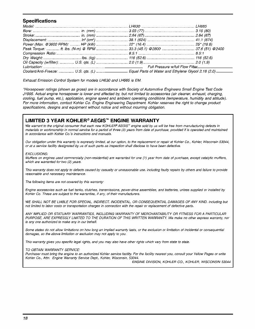
Specifications Model LH630 LH685 Bore: .............................................. in. (mm) ............................... 3.03 (77) ................................................. 3.15 (80) Stroke: ............................................ in. (mm) ............................... 2.64 (67) ................................................. 2.64 (67) Displacement: ................................. in3 (cm3) ............................... 38.1 (624) .............................................. 41.1 (674) Power (Max. 633600 RPM): 25* (18.6)
Compression Ratio: ...................................................................... 8.5: 1 ....................................................... 8.5: 1 Dry Weight: ..............
Lubrication: ............................................................
Peak Torque: ............. ft. Ibs.
Oil Capacity (w/filter) U.S. qts. (L) 2.0 (1.9) 2.0 (1.9)
CoolanVAnti-Freeze: ............... U. S. qts. (L) ........
................................ 37.6 (51) Q2400
....... Ibs. (kg) ............................... 116 (52.6) ............................................... 116 (52.6)
. . Full Pressure w/full Flow Filter Equal Parts of Water and Ethylene Glycol 2.18 (2.0)
Exhaust Emission Control System for models LH630 and LH685 is EM.
*Horsepower ratings (shown as gross) are in accordance with Society of Automotive Engineers Small Engine Test Code J1995. Actual engine horsepower is lower and affected bl: but not limited to accessories (air cleaner, exhaust, charging, cooling, fuel pump, etc.), application, engine speed and ambient operating conditions (temperature, humidity and altitude). For more information, contact Kohler Co. Engine Engineering Department. Kohler reserves the right to change product specifications, designs and equipment without notice and without incurring obligation.
LIMITED 3 YEAR KOHLER@ AEGIS'" ENGINE WARRANTY We warrant to the original consumer that each new KOHLEPAEGIS" engine sold by us will be free from manufacturing defects in materials or workmanship in normal service for a period of three (3) years from date of purchase, provided if is operated and maintained in accordance with Kohler Co.3 instructions and manuals.
Our obligation under this warranty is expressly limited, at our option, to the replacement or repair at Kohler Co., Kohlec Wisconsin 53044, or at a service facility designated by us of such parts as inspection shall disclose to have been defective.
EXCLUSIONS: Mufflers on engines used commercially (non-residential) are warranted for one (1) year from date of purchase, except catalytic mufflers, which are warranted for two (2) years.
This warranty does not apply to defects caused by casualty or unreasonable use, including faulty repairs by others and failure to provide reasonable and necessary maintenance.
The following items are not covered by this warranty:
Engine accessories such as fuel tanks, clutches, transmissions, power-drive assemblies, and batteries, unless supplied or installed by Kohler Co. These are subject to the warranties, if any, of their manufacturers.
WE SHALL NOT BE LIABLE FOR SPECIAL, INDIRECT; INCIDENTAL, OR CONSEQUENTIAL DAMAGES OF ANY KIND, including but not limited to labor costs or transportation charges in connection with the repair or replacement of defective parts.
ANY IMPLIED OR STATUARY WARRANTIES, INCLUDING WARRANTY OF MERCHANTABILITY OR FITNESS FOR A PARTICULAR PURPOSE, ARE EXPRESSLY LIMITED TO THE DURATION OF THIS WRITTEN WARRANTY. We make no other express warranty, nor is any one authorized to make any in our behalf.
Some states do not allow limitations on how long an implied warranty lasts, or the exclusion or limitation of incidental or consequential damages, so the above limitation or exclusion may not apply to you.
This warranty gives you specific legal rights, and you may also have other rights which vary from state to state.
TO OBTAIN WARRANTY SERVICE: Purchaser must bring the engine to an authorized Kohler service facilitg For the facility nearest you, consult your Yellow Pages or write Kohler Co., Attn: Engine Warranty Service Dept., Kohler, Wisconsin, 53044.
ENGINE DIVISION, KOHLER CO., KOHLER, WISCONSIN 53044

KOHLER CO. FEDERAL AND CALIFORNIA EMISSION CONTROL SYSTEMS
LIMITED WARRANTY SMALL OFF-ROAD ENGINES
The US. Environmental Protection Agency (EPA), the California Air Resources Board (CARB), and Kohler Co. are pleased to explain the Federal and California Emission Control Systems Warranty on your small off-road equipment engine. For California, engines produced in 1995 and later must be designed, built and equipped to meet the state’s stringent anti-smog standards. In other states, 1997 and later model year engines must be designed, built and equipped, to meet the US. EPA regulations for small non-road engines. The engine must be free from defects in materials and workmanship which cause it to fail to conform with US. EPA standards for the first two years of sngine use from the date of sale to the ultimate purchaser. Kohler Co. must warrant the emission control system on the engine for the oeriod of time listed above, provided there has been no abuse, neglect or improper maintenance.
The emission control system may include parts such as the carburetor or fuel injection system, the ignition system, and catalytic converter. 4lso included are the hoses, belts and connectors and other emission related assemblies.
Where a warrantable condition exists, Kohler Co. will repair the engine at no cost, including diagnosis (if the diagnostic work is performed ai an authorized dealer), parts and labor.
MANUFACTURER’S WARRANTY COVERAGE Engines produced in 1995 or later are warranted for two years in California. In other states, 1997 and later model year engines are warranted for two years. If any emission related part on the engine is defective, the part will be repaired or replaced by Kohler Co. free of sharge.
OWNER’S WARRANTY RESPONSIBILITIES (a) The engine owner is responsible for the performance of the required maintenance listed in the owner’s manual. Kohler Co.
recommends that you retain all receipts covering maintenance on the engine, But Kohler Co. cannot deny warranty solely for the lack of receipts or for your failure to assure that all scheduled maintenance was performed.
(b) Be aware, however, that Kohler Co. may deny warranty coverage if the engine or a part has failed due to abuse, neglect, improper maintenance or unapproved modifications.
(c) For warranty repairs, the engine must be presented to a Kohler Co. service center as soon as a problem exists. Call 1-800-544-2444 or access our web site at: www.kohlerengines.com for the names of the nearest service centers. The warranty repairs should be completed in a reasonable amount of time, not to exceed 30 days.
If you have any questions regarding warranty rights and responsibilities, you should contact Kohler Co. at 1-920-457-4441 and ask for an Engine Service representative.
COVERAGE Kohler Co. warrants to the ultimate purchaser and each subsequent purchaser that the engine will be designed, built and equipped, at the time of sale, to meet all applicable regulations. Kohler Co. also warrants to the initial purchaser and each subsequent purchaser, that the sngine is free from defects in materials and workmanship which cause the engine to fail to conform with applicable regulations for a period 3f two years.
Engines produced in 1995 or later are warranted for two years in California. For 1997 and later model years, EPA requires manufacturers to warrant engines for two years in all other states. These warranty periods will begin on the date the engine is purchased by the initial ourchaser. If any emission related part on the engine is defective, the part will be replaced by Kohler Co. at no cost to the owner. Kohler Go. is liable for damages to other engine components caused by the failure of a warranted part still under warranty.
Kohler Co. shall remedy warranty defects at any authorized Kohler Co. engine dealer or warranty station. Warranty repair work done at an authorized dealer or warranty station shall be free of charge to the owner if such work determines that a warranted part is defective.
Listed below are the parts covered by the Federal and California Emission Control Systems Warranty. Some parts listed below may require scheduled maintenance and are warranted up to the first scheduled replacement point for that part. The warranted parts are:
Oxygen sensor (if equipped) Intake manifold (if equipped) Exhaust manifold (if equipped) Catalytic muffler (if equipped) Fuel metering valve (if equipped) Spark advance module (if equipped) Crankcase breather
Ignition module(s) with high tension lead Gaseous fuel regulator (if equipped) Electronic control unit (if equipped) Carburetor or fuel injection system Fuel lines (if equipped) Air filtec fuel filter, and spark plugs (only to first scheduled replacement point)
Continued on next page.
19
LIMITATIONS This Emission Control Systems Warranty shall not cover any of the following:
(a) repair or replacement required because of misuse or neglect, improper maintenance, repairs improperly performed or replacements not conforming to Kohler Co. specifications that adversely affect performance and/or durability and alterations or modifications not recommended or approved in writing by Kohler Co.,
replacement of parts and other services and adjustments necessary for required maintenance at and after the first scheduled replacement point,
consequential damages such as loss of time, inconvenience, loss of use of the engine or equipment, etc.,
diagnosis and inspection fees that do not result in eligible warranty service being performed, and
any add-on or modified part, or malfunction of authorized parts due to the use of add-on or modified parts,
(b)
(c)
(d)
(e)
MAINTENANCE AND REPAIR REQUIREMENTS The owner is responsible for the proper use and maintenance of the engine. Kohler Co. recommends that all receipts and records covering the performance of regular maintenance be retained in case questions arise. If the engine is resold during the warranty period, the maintenance records should be transferred to each subsequent owner. Kohler Co. reserves the right to deny warranty coverage if the engine has not been properly maintained; however, Kohler Co. may not deny warranty repairs solely because of the lack of repair maintenance or failure to keep maintenance records.
Normal maintenance, replacement or repair of emission control devices and systems may be performed by any repair establishment or individual; however, warranty repairs must be performed by a Kohler authorized service center. Any replacement part or service that is equivalent in performance and durability may be used in non-warranty maintenance or repairs, and shall not reduce the warranty obligations of the engine manufacturer.
FOR SALES AND SERVICE INFORMATION IN U.S. AND CANADA, CALL
1-800-544-2444
U
60- 110 RUN'"
ENGINE DIVISION, KOHLER CO., KOHLER, WISCONSIN 53044
FORM NO.: TP-2512
MAILED: LITHO IN U.S.A.