Embed Size (px)
Citation preview
TRM/416 Hardware Documentation
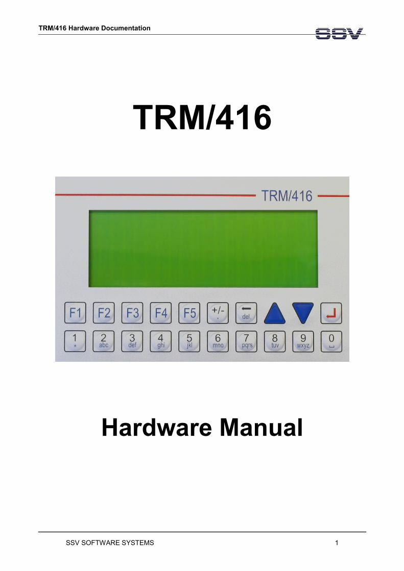
TRM/416
Hardware Manual
SSV SOFTWARE SYSTEMS 1
TRM/416 : Documentation
SSV SOFTWARE SYSTEMS 2
TRM/416: Parts of the TRM/416
Content
Parts of the TRM/416........................................................................................................................................ 4
Display.............................................................................................................................................................. 4
Front Panel Keyboard....................................................................................................................................... 4
Front Panel Keyboard: Keycodes..................................................................................................................... 5
Basic Board BB/416.......................................................................................................................................... 6
DIL/NetPC......................................................................................................................................................... 6
Basic Board BB/416 Connectors - Picture........................................................................................................7
Connector – Pinouts......................................................................................................................................... 8
Jumpers on TRM/416..................................................................................................................................... 11
Reserved / not available I/O-Addresses on TRM/416.....................................................................................13
Electrical characteristic TRM/416...................................................................................................................14
Pictures........................................................................................................................................................... 15
Contact........................................................................................................................................................... 15
Notes to this document................................................................................................................................... 15
SSV SOFTWARE SYSTEMS 3
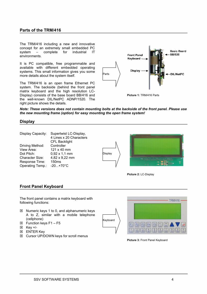
Parts of the TRM/416
The TRM/416 including a new and innovative concept for an extremely small embedded PC system – complete for industrial IT environments.
It is PC compatible, free programmable and available with different embedded operating systems. This small information gives you some more details about the system itself.
The TRM/416 is an open frame Ethernet PC system. The backside (behind the front panel matrix keyboard and the high resolution LC-Display) consists of the base board BB/416 and the well-known DIL/NetPC ADNP/1520. The right picture shows the details.
Picture 1: TRM/416 Parts
Note: These versions does not contain mounting bolts at the backside of the front panel. Please use the new mounting frame (option) for easy mounting the open frame system!
Display
Display Capacity:
Driving Method:View Area:Dot Pitch:Character Size:Response Time:Operating Temp.:
Supertwist LC-Display,4 Lines x 20 CharactersCFL BacklightController121 x 40 mm0,92 x 1,1 mm4,82 x 9,22 mm150ms-20...+70°C
Picture 2: LC-Display
Front Panel Keyboard
The front panel contains a matrix keyboard with following functions:
Numeric keys 1 to 0, and alphanumeric keys A to Z, similar with a mobile telephone (cellphone)
Function keys F1 – F5 Key +/- ENTER Key Cursor UP/DOWN keys for scroll menus
Picture 3: Front Panel Keyboard
SSV SOFTWARE SYSTEMS 4
Parts
Display
Keyboard
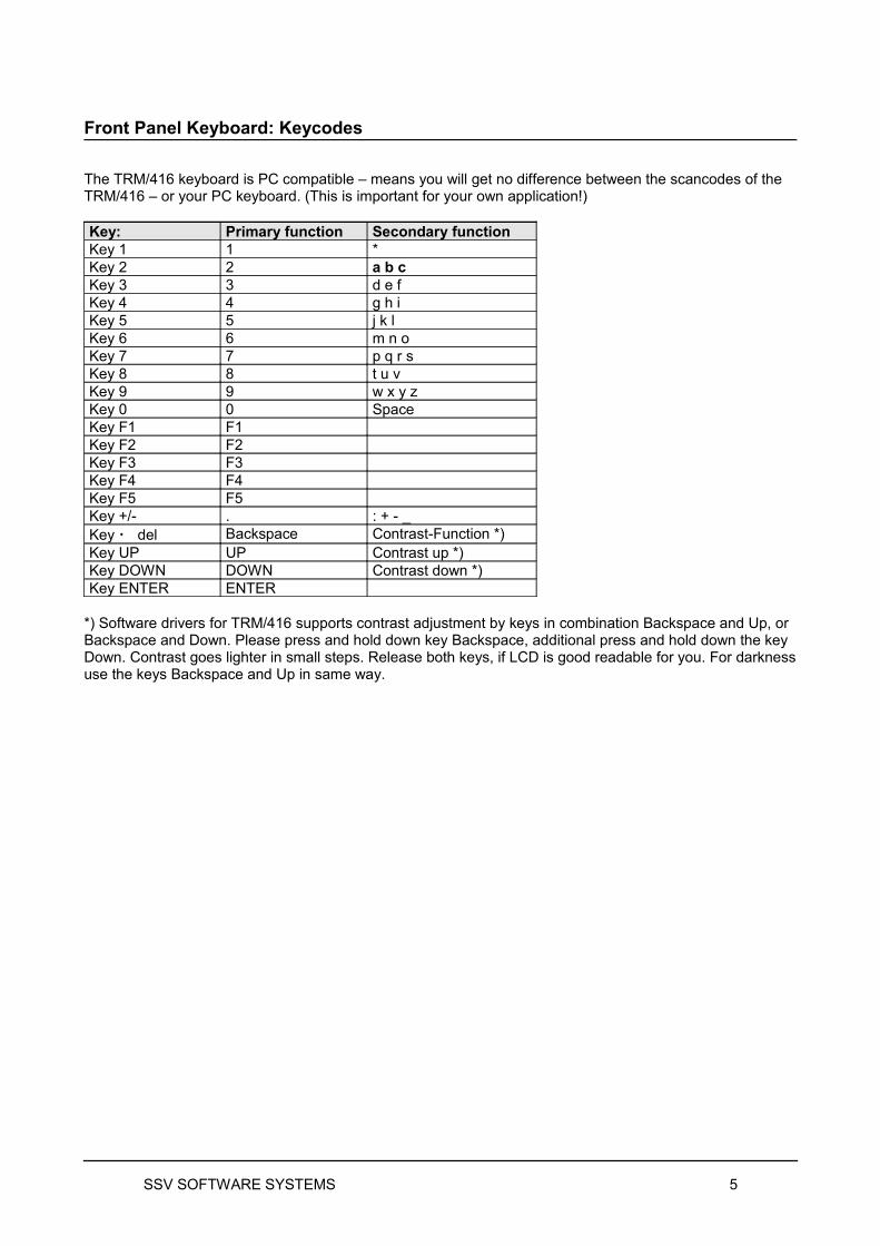
Front Panel Keyboard: Keycodes
The TRM/416 keyboard is PC compatible – means you will get no difference between the scancodes of the TRM/416 – or your PC keyboard. (This is important for your own application!)
Key: Primary function Secondary functionKey 1 1 *Key 2 2 a b cKey 3 3 d e fKey 4 4 g h iKey 5 5 j k lKey 6 6 m n oKey 7 7 p q r sKey 8 8 t u vKey 9 9 w x y zKey 0 0 SpaceKey F1 F1Key F2 F2Key F3 F3Key F4 F4Key F5 F5Key +/- . : + - _Key del Backspace Contrast-Function *)Key UP UP Contrast up *)Key DOWN DOWN Contrast down *)Key ENTER ENTER
*) Software drivers for TRM/416 supports contrast adjustment by keys in combination Backspace and Up, or Backspace and Down. Please press and hold down key Backspace, additional press and hold down the key Down. Contrast goes lighter in small steps. Release both keys, if LCD is good readable for you. For darkness use the keys Backspace and Up in same way.
SSV SOFTWARE SYSTEMS 5
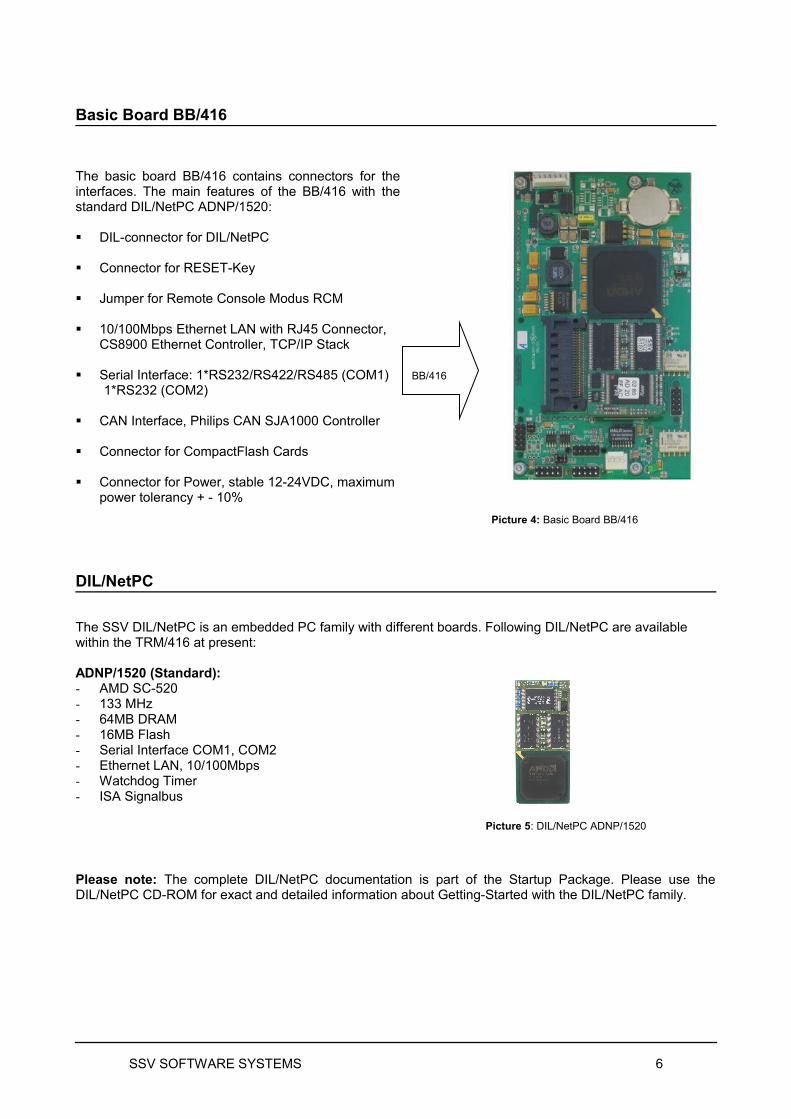
Basic Board BB/416
The basic board BB/416 contains connectors for the interfaces. The main features of the BB/416 with the standard DIL/NetPC ADNP/1520:
DIL-connector for DIL/NetPC
Connector for RESET-Key
Jumper for Remote Console Modus RCM
10/100Mbps Ethernet LAN with RJ45 Connector, CS8900 Ethernet Controller, TCP/IP Stack
Serial Interface: 1*RS232/RS422/RS485 (COM1)1*RS232 (COM2)
CAN Interface, Philips CAN SJA1000 Controller
Connector for CompactFlash Cards
Connector for Power, stable 12-24VDC, maximum power tolerancy + - 10%
Picture 4: Basic Board BB/416
DIL/NetPC
The SSV DIL/NetPC is an embedded PC family with different boards. Following DIL/NetPC are available within the TRM/416 at present:
ADNP/1520 (Standard):- AMD SC-520- 133 MHz- 64MB DRAM- 16MB Flash- Serial Interface COM1, COM2 - Ethernet LAN, 10/100Mbps- Watchdog Timer- ISA Signalbus
Picture 5: DIL/NetPC ADNP/1520
Please note: The complete DIL/NetPC documentation is part of the Startup Package. Please use the DIL/NetPC CD-ROM for exact and detailed information about Getting-Started with the DIL/NetPC family.
SSV SOFTWARE SYSTEMS 6
BB/416
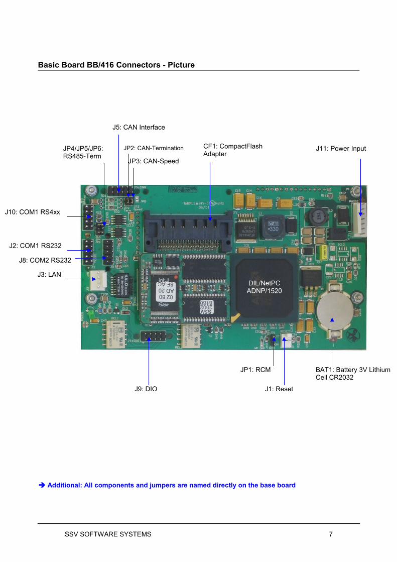
Basic Board BB/416 Connectors - Picture
SSV SOFTWARE SYSTEMS 7
J1: Reset
JP1: RCM
J11: Power Input
BAT1: Battery 3V Lithium Cell CR2032
CF1: CompactFlashAdapter
J5: CAN Interface
JP3: CAN-Speed
J10: COM1 RS4xx
J3: LAN
JP2: CAN-Termination
J2: COM1 RS232
Additional: All components and jumpers are named directly on the base board
J9: DIO
JP4/JP5/JP6:RS485-Term
DIL/NetPCADNP/1520
J8: COM2 RS232
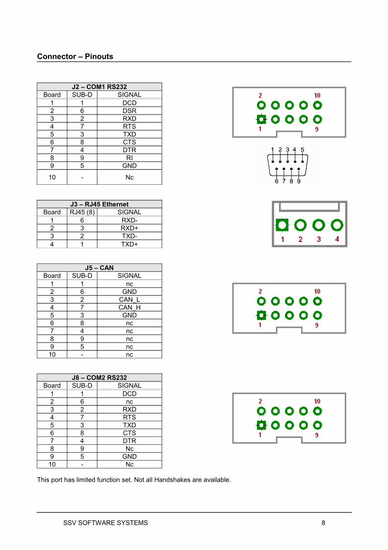
Connector – Pinouts
J2 – COM1 RS232Board SUB-D SIGNAL
1 1 DCD2 6 DSR3 2 RXD4 7 RTS5 3 TXD6 8 CTS7 4 DTR8 9 RI9 5 GND
10 - Nc
J3 – RJ45 EthernetBoard RJ45 (8) SIGNAL
1 6 RXD-2 3 RXD+3 2 TXD-4 1 TXD+
J5 – CANBoard SUB-D SIGNAL
1 1 nc2 6 GND3 2 CAN_L4 7 CAN_H5 3 GND6 8 nc7 4 nc8 9 nc9 5 nc
10 - nc
J8 – COM2 RS232Board SUB-D SIGNAL
1 1 DCD2 6 nc3 2 RXD4 7 RTS5 3 TXD6 8 CTS7 4 DTR8 9 Nc9 5 GND
10 - Nc
This port has limited function set. Not all Handshakes are available.
SSV SOFTWARE SYSTEMS 8
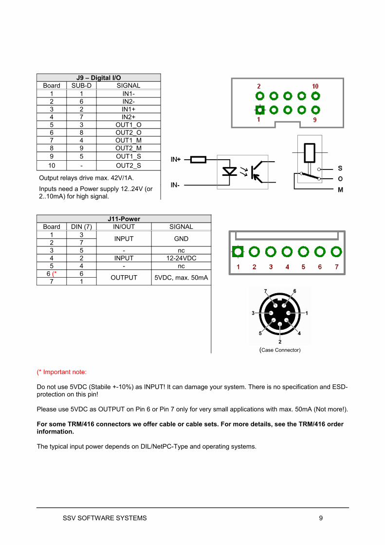
J9 – Digital I/OBoard SUB-D SIGNAL
1 1 IN1-2 6 IN2-3 2 IN1+4 7 IN2+5 3 OUT1_O6 8 OUT2_O7 4 OUT1_M8 9 OUT2_M9 5 OUT1_S
10 - OUT2_S
Output relays drive max. 42V/1A.
Inputs need a Power supply 12..24V (or 2..10mA) for high signal.
J11-Power
(Case Connector)
Board DIN (7) IN/OUT SIGNAL1 3
INPUT GND2 73 5 - nc4 2 INPUT 12-24VDC5 4 - nc
6 (* 6OUTPUT 5VDC, max. 50mA
7 1
(* Important note:
Do not use 5VDC (Stabile +-10%) as INPUT! It can damage your system. There is no specification and ESD-protection on this pin!
Please use 5VDC as OUTPUT on Pin 6 or Pin 7 only for very small applications with max. 50mA (Not more!).
For some TRM/416 connectors we offer cable or cable sets. For more details, see the TRM/416 order information.
The typical input power depends on DIL/NetPC-Type and operating systems.
SSV SOFTWARE SYSTEMS 9
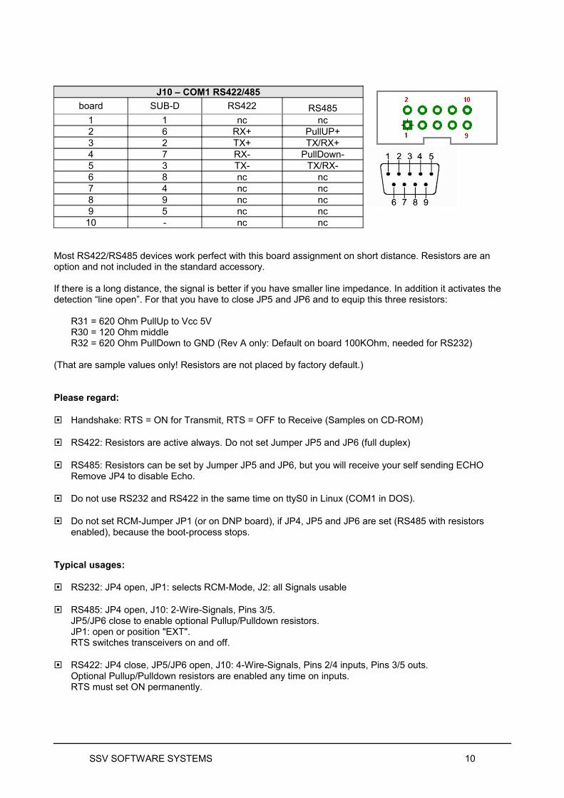
J10 – COM1 RS422/485
board SUB-D RS422 RS4851 1 nc nc2 6 RX+ PullUP+3 2 TX+ TX/RX+4 7 RX- PullDown-5 3 TX- TX/RX-6 8 nc nc7 4 nc nc8 9 nc nc9 5 nc nc
10 - nc nc
Most RS422/RS485 devices work perfect with this board assignment on short distance. Resistors are an option and not included in the standard accessory.
If there is a long distance, the signal is better if you have smaller line impedance. In addition it activates the detection “line open”. For that you have to close JP5 and JP6 and to equip this three resistors:
R31 = 620 Ohm PullUp to Vcc 5VR30 = 120 Ohm middleR32 = 620 Ohm PullDown to GND (Rev A only: Default on board 100KOhm, needed for RS232)
(That are sample values only! Resistors are not placed by factory default.)
Please regard:
Handshake: RTS = ON for Transmit, RTS = OFF to Receive (Samples on CD-ROM)
RS422: Resistors are active always. Do not set Jumper JP5 and JP6 (full duplex)
RS485: Resistors can be set by Jumper JP5 and JP6, but you will receive your self sending ECHORemove JP4 to disable Echo.
Do not use RS232 and RS422 in the same time on ttyS0 in Linux (COM1 in DOS).
Do not set RCM-Jumper JP1 (or on DNP board), if JP4, JP5 and JP6 are set (RS485 with resistors enabled), because the boot-process stops.
Typical usages:
RS232: JP4 open, JP1: selects RCM-Mode, J2: all Signals usable
RS485: JP4 open, J10: 2-Wire-Signals, Pins 3/5.JP5/JP6 close to enable optional Pullup/Pulldown resistors.JP1: open or position "EXT".RTS switches transceivers on and off.
RS422: JP4 close, JP5/JP6 open, J10: 4-Wire-Signals, Pins 2/4 inputs, Pins 3/5 outs.Optional Pullup/Pulldown resistors are enabled any time on inputs.RTS must set ON permanently.
SSV SOFTWARE SYSTEMS 10
Jumpers on TRM/416
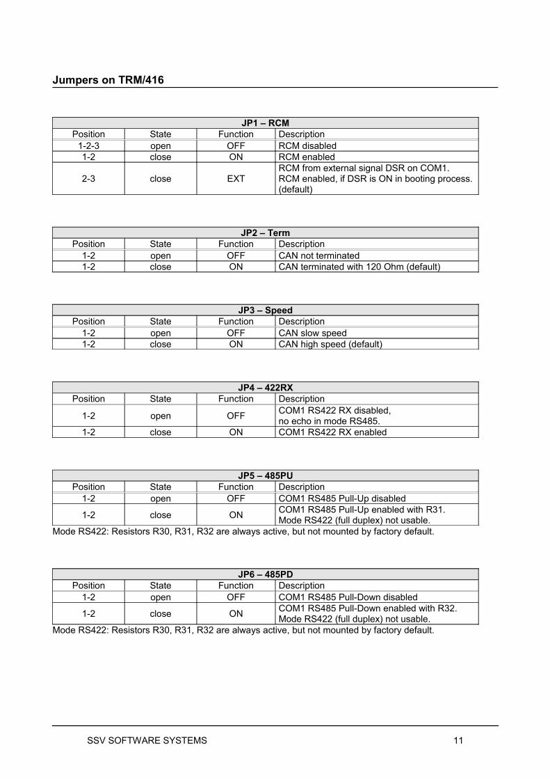
JP1 – RCMPosition State Function Description
1-2-3 open OFF RCM disabled1-2 close ON RCM enabled
2-3 close EXTRCM from external signal DSR on COM1.RCM enabled, if DSR is ON in booting process. (default)
JP2 – TermPosition State Function Description
1-2 open OFF CAN not terminated 1-2 close ON CAN terminated with 120 Ohm (default)
JP3 – SpeedPosition State Function Description
1-2 open OFF CAN slow speed1-2 close ON CAN high speed (default)
JP4 – 422RXPosition State Function Description
1-2 open OFFCOM1 RS422 RX disabled, no echo in mode RS485.
1-2 close ON COM1 RS422 RX enabled
JP5 – 485PUPosition State Function Description
1-2 open OFF COM1 RS485 Pull-Up disabled
1-2 close ONCOM1 RS485 Pull-Up enabled with R31.Mode RS422 (full duplex) not usable.
Mode RS422: Resistors R30, R31, R32 are always active, but not mounted by factory default.
JP6 – 485PDPosition State Function Description
1-2 open OFF COM1 RS485 Pull-Down disabled
1-2 close ONCOM1 RS485 Pull-Down enabled with R32.Mode RS422 (full duplex) not usable.
Mode RS422: Resistors R30, R31, R32 are always active, but not mounted by factory default.
SSV SOFTWARE SYSTEMS 11
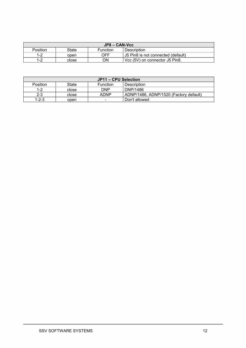
JP8 – CAN-VccPosition State Function Description
1-2 open OFF J5 Pin8 is not connected (default)1-2 close ON Vcc (5V) on connector J5 Pin8.
JP11 – CPU SelectionPosition State Function Description
1-2 close DNP DNP/14862-3 close ADNP ADNP/1486, ADNP/1520 (Factory default)
1-2-3 open - Don't allowed
SSV SOFTWARE SYSTEMS 12
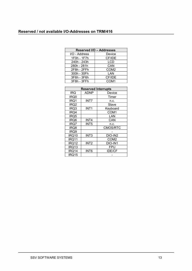
Reserved / not available I/O-Addresses on TRM/416
Reserved I/O – Addresses I/O - Address Device1F0h - 1F7h CF/IDE240h - 243h LCD280h - 281h CAN2F8h - 2FFh COM2300h - 30Fh LAN3F6h - 3F6h CF/IDE3F8h - 3FFh COM1
Reserved InterruptsIRQ ADNP Device
IRQ0 TimerIRQ1 INT7 n.c.IRQ2 SlaveIRQ3 INT1 KeyboardIRQ4 COM1IRQ5 LANIRQ6 INT4 CANIRQ7 INT5 n.c.IRQ8 CMOS/RTCIRQ9 -
IRQ10 INT3 DIO-IN2IRQ11 COM2IRQ12 INT2 DIO-IN1IRQ13 FPUIRQ14 INT6 IDE/CFIRQ15 -
SSV SOFTWARE SYSTEMS 13
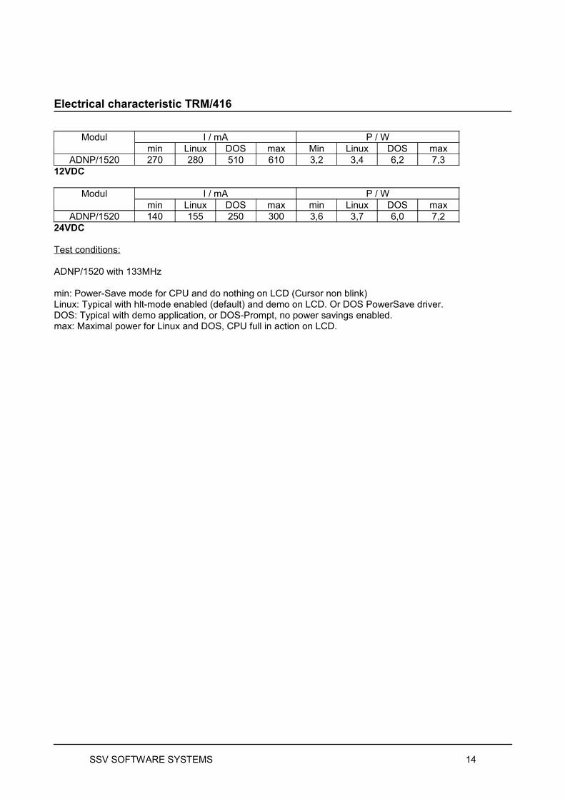
Electrical characteristic TRM/416
Modul I / mA P / Wmin Linux DOS max Min Linux DOS max
ADNP/1520 270 280 510 610 3,2 3,4 6,2 7,312VDC
Modul I / mA P / Wmin Linux DOS max min Linux DOS max
ADNP/1520 140 155 250 300 3,6 3,7 6,0 7,224VDC
Test conditions:
ADNP/1520 with 133MHz
min: Power-Save mode for CPU and do nothing on LCD (Cursor non blink)Linux: Typical with hlt-mode enabled (default) and demo on LCD. Or DOS PowerSave driver.DOS: Typical with demo application, or DOS-Prompt, no power savings enabled.max: Maximal power for Linux and DOS, CPU full in action on LCD.
SSV SOFTWARE SYSTEMS 14
SSV SOFTWARE SYSTEMS 15
Additional Information
Compact Flash Card: The TRM/416 Starter Kit II with ADNP can use compact flash cards for memory upgrade. The DNP version does not allow the using of compact flash cards.
Power: Use 12...24 VDC in stable version for power! Max tolerancy is + / - 10% of this value. Exceeding this value for long term use or in power peeks will damage the system!
CAN Interface: The TRM/416 contains an on-board CAN controller, type Philips SJA1000. Please refer our special add-on documentation for the CAN interface: user-doc/add-on
Digital I/O: The TRM/416 contains a digital I/O with 2bit inport and 2bit outport. You can address them via PORT A / Port B of the (A)DNP. Please refer our DIO software samples for using.
LCD Contrast: Some TRM/416 contains an adjustable contrast via software, useable with a keyboard combination. Refer software drivers for more information.
LCD Backlight: Depending on production series we deliver the TRM/416 with a standard LCD or with a backlighted LCD.If you have got a version with backlighted LCD, the backlight is always on. It is not possible to turn to backlight on or off.
Web Server: If you want to install a web server for the TRM/416, please explore the DIL/NetPC CD. The web server is a part of the DIL/NetPC. We put the web server httpd on the CD (and the documentation for using) too.
RAM Disc, Drive C and D: The internal flash memory is drive C: We prepared the TRM/416 with a RAM disc, you can use this as drive D: – or if you are using a compact flash card E:We recommend to use the RAM disc for exploring our samples. This is the faster way (for downloads) and you save the flash life with using the RAM disc.
Case Version – Evaluation System:
We recommend to use the starter kit as open frame system. It is easier to use on a table for the programming and software development phase.
If you want to begin with a case version, you have to open the TRM/816 case to use all the evaluation features of the TRM/416, e.g. RCM mode etc.
If you have finished your software development, you can close the system and use the case version again.
SSV SOFTWARE SYSTEMS 16
Pictures
Contact
Manufacturer:SSV Software Systems GmbHDünenweg 5 D-30419 Hannover / Germanywww.ssv-industrial.de
General Distributor:AE SYSTEME www.terminal-systemsAm Güterbahnhof 15D-31303 Burgdorf / Germanywww.terminal-systems.de
Notes to this document
Revision Date Name1.00 15.05.2007 First version hne/smu1.01 17.07.2007 Changes on IO-Map, IRQ-Map, Contrast Hotkeys hne
26.03.10 Updated adress information and bugfixes hjw
SSV Embedded Systems is the manufacturer of this product. We may change technical features or descriptions without any notice. We do not give any warranty of the information of this document. Copyright © SSV EMBEDDED SYSTEMS 2007. All rights reserved.
SSV SOFTWARE SYSTEMS 17