Embed Size (px)
Citation preview

Understanding and Embracing the Complexities ofthe Molecular Communication Channel in Liquids
Jiaming Wang, Dongyin Hu, Chirag Shetty, Haitham Hassanieh
University of Illinois at Urbana-Champaign
{jw27, dyhu, cshetty2, haitham}@illinois.edu
ABSTRACTMolecular communication has recently gained a lot of
interest due to its potential to enable micro-implants to com-
municate by releasing molecules into the bloodstream. In
this paper, we aim to explore the molecular communication
channel through theoretical and empirical modeling in order
to achieve a better understanding of its characteristics, which
tend to be more complex in practice than traditional wireless
and wired channels. Our study reveals two key new charac-
teristics that have been overlooked by past work. Specifically,
the molecular communication channel exhibits non-causal
inter-symbol-interference and a long delay spread, that ex-
tends beyond the channel coherence time, which limit decod-
ing performance. To address this, we design, `-Link a molec-
ular communication protocol and decoder that accounts for
these new insights. We build a testbed to experimentally
validate our findings and show that `-Link can improve the
achievable data rates with significantly lower bit error rates.
CCS CONCEPTS• Networks→ Cyber-physical networks; Physical links.
KEYWORDSMolecular Communication, Diffusion, Non-Causal Channel,
Micro-Implants, Inter-Symbol-Interference, Viterbi.
ACM Reference Format:Jiaming Wang, Dongyin Hu, Chirag Shetty, Haitham Hassanieh.
2020. Understanding and Embracing the Complexities of the Molec-
ular Communication Channel in Liquids. In The 26th Annual Inter-national Conference on Mobile Computing and Networking (MobiCom’20), September 21–25, 2020, London, United Kingdom. ACM, New
York, NY, USA, 15 pages. https://doi.org/10.1145/3372224.3419191
Permission to make digital or hard copies of all or part of this work for
personal or classroom use is granted without fee provided that copies are not
made or distributed for profit or commercial advantage and that copies bear
this notice and the full citation on the first page. Copyrights for components
of this work owned by others than ACMmust be honored. Abstracting with
credit is permitted. To copy otherwise, or republish, to post on servers or to
redistribute to lists, requires prior specific permission and/or a fee. Request
permissions from [email protected].
MobiCom ’20, September 21–25, 2020, London, United Kingdom© 2020 Association for Computing Machinery.
ACM ISBN 978-1-4503-7085-1/20/09. . . $15.00
https://doi.org/10.1145/3372224.3419191
1 INTRODUCTIONMolecular communication (MC) has emerged as a promis-
ing technology for communication through fluids such as
micro-implants communicating through the bloodstream or
sensors communicating through industrial pipes [4, 20, 34].
In MC, a device can transmit data by releasing molecules
into the fluid which are then transported and detected at a
receiver [55]. For example, a device can release molecules
to encode a “1” bit and release nothing to encode a “0” bit.
The receiver can measure the concentration of molecules to
determine whether the transmitted bit was a “1” or a “0”.
Molecular communication has the potential to enable mi-
cro and nano-implants to communicate with each other in-
side the human body and coordinate sensing and actuation
tasks. Recent advances in biomedical sciences have in fact
led to the development of nano-implants that can sense hu-
man vitals from inside the body and even travel through
the bloodstream to perform targeted drug delivery and treat-
ment [12, 30, 55]. There is significant interest in enhancing
the operation of such implants by connecting them using
MC [4, 5, 9, 10, 20–23, 34, 53]. MC presents a suitable alterna-
tive to other communication technologies such as wireless.
In particular, RF signals do not propagate well in fluids and
form factor constraints prevent scaling RF radios to micro
and nano-dimensions [40, 56, 66]. In contrast, for MC, re-
searchers can design synthetic cells that send and receive
molecular signals [17, 52, 57], nano-scale Lab-on-a-Chip that
monitor chemical content [30, 54, 61], and bio-implants that
collect and process data [41, 43, 51].
While there is still a long way to realize the above vision,
this paper takes steps to achieve a better understanding of
the characteristics of the MC channel from both theoretical
and empirical perspectives. TheMC channel tends to bemore
complex in practice than standard RF, optical, or copper wire
channels [28]. Understanding and addressing the differences
between these channels and MC allows us to improve the
performance of molecular communication.
There has been a significant amount of work on theoret-
ically modeling the MC channel [15, 16, 46, 47, 47, 58, 59,
62, 65, 68]. However, these models tend to be overly simpli-
fied with assumptions that do not hold in practice (e.g. no
inter-symbol-interference) or overly fitted to a closed form
equation that does not capture practical constraints and im-
perfections (see section 7 for more details). Hence, these
models are only evaluated through simulations. On the other
hand, there has been little work on empirically validating
the MC channel models in fluids [19, 24, 60]. Performance in
these testbeds yields at best a data rate of 4 bits/sec with 3%
bit error rate (BER) [18]. However, this is achieved by using
deep neural networks to decode MC signals without explic-
itly learning or modeling the channel. While promising, the
approach requires the network to be trained for the specific
channels being tested and hence, might not generalize to
new channels that the neural network has not seen before
as we show in section 6.
In this paper, we build on the above theoretical and empiri-
cal work to capture the characteristics of the MC channel.We
introduce two new key properties that have been overlooked
by past work on MC. Specifically, the molecular communica-
tion channel exhibits non-causal inter-symbol-interference
and a long delay spread that extends beyond the channel
coherence time. We show how to leverage these new insights
to improve the decoding performance and achieve a higher
bit rate with lower bit errors. We also empirically validate
and incorporate insights introduced by past work such as the
presence of signal dependent noise and the channel response
resulting from the statistical behavior of molecular diffusion.
Our work, in particular, reveals the following two insights:
• Non-causal Inter-Symbol-Interference:Due to the sta-tistical nature of diffusion, molecules released at the trans-
mitter can arrive at significantly different times at the
receiver even if they follow the same path. As a result,
the molecules of previous symbols can arrive late creat-
ing inter-symbol-interference (ISI). Molecules of future
symbols can arrive earlier than molecules of the current
symbol creating a non-causal ISI as well. In contrast, in
standard communication systems, ISI is caused only by pre-
viously transmitted symbols which can be decoded first to
eliminate their ISI as opposed to future unknown symbols
that cannot be decoded before the current symbol.
• Long Delay Spread vs. Coherence Time:1 In MC chan-
nels, the channel delay spread can be long (1 to 4 seconds)
which is of a similar order to the channel coherence time
(a few 10s of seconds) [3, 26]. Hence, the channel varies
only slightly slower than the time it takes us to estimate
it. Compare this to RF channels where the delay spread
(0.1`𝑠 − 10`𝑠) is orders of magnitude smaller than the co-
herence time (10𝑚𝑠 − 100𝑚𝑠) and we can quickly estimate
the channel and assume to be constant for the duration of
1Coherence time refers to the time for which the channel impulse response
can be considered as static. Delay spread refers to the length of the chan-
nel impulse response, i.e., the time between the start and end of particles
corresponding to the same symbol arriving at a receiver.
RX EC Reader Background Flow Pump
NaClTX & RX Controllers
bit 1 bit 0
TX Pumps
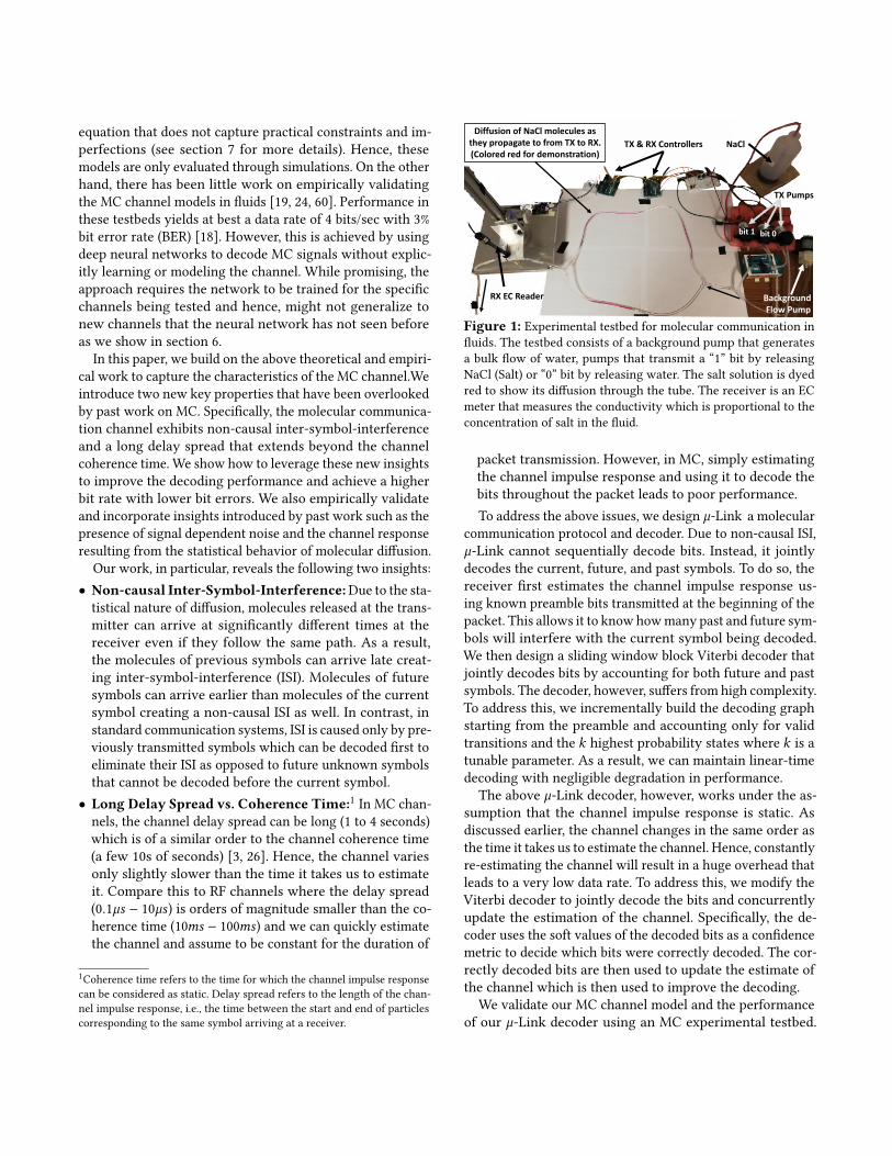
Diffusion of NaCl molecules as they propagate to from TX to RX. (Colored red for demonstration)
Figure 1: Experimental testbed for molecular communication in
fluids. The testbed consists of a background pump that generates
a bulk flow of water, pumps that transmit a “1” bit by releasing
NaCl (Salt) or “0” bit by releasing water. The salt solution is dyed
red to show its diffusion through the tube. The receiver is an EC
meter that measures the conductivity which is proportional to the
concentration of salt in the fluid.
packet transmission. However, in MC, simply estimating
the channel impulse response and using it to decode the
bits throughout the packet leads to poor performance.
To address the above issues, we design `-Link a molecular
communication protocol and decoder. Due to non-causal ISI,
`-Link cannot sequentially decode bits. Instead, it jointly
decodes the current, future, and past symbols. To do so, the
receiver first estimates the channel impulse response us-
ing known preamble bits transmitted at the beginning of the
packet. This allows it to know howmany past and future sym-
bols will interfere with the current symbol being decoded.
We then design a sliding window block Viterbi decoder that
jointly decodes bits by accounting for both future and past
symbols. The decoder, however, suffers from high complexity.
To address this, we incrementally build the decoding graph
starting from the preamble and accounting only for valid
transitions and the 𝑘 highest probability states where 𝑘 is a
tunable parameter. As a result, we can maintain linear-time
decoding with negligible degradation in performance.
The above `-Link decoder, however, works under the as-
sumption that the channel impulse response is static. As
discussed earlier, the channel changes in the same order as
the time it takes us to estimate the channel. Hence, constantly
re-estimating the channel will result in a huge overhead that
leads to a very low data rate. To address this, we modify the
Viterbi decoder to jointly decode the bits and concurrently
update the estimation of the channel. Specifically, the de-
coder uses the soft values of the decoded bits as a confidence
metric to decide which bits were correctly decoded. The cor-
rectly decoded bits are then used to update the estimate of
the channel which is then used to improve the decoding.
We validate our MC channel model and the performance
of our `-Link decoder using an MC experimental testbed.

The testbed follows a similar approach to past experimental
testbeds on validating the molecular communication chan-
nel [19, 60]. Our testbed is shown in Fig. 1. It consists of a
network of narrow tubes and a pump that maintains a con-
stant flow of water in the tubes. Another pump is used as
a transmitter to release salt particles in the flowing liquid
and a sensor is used as the receiver to measure the presence
and concentration of these particles (See section 5 for more
details). Our results confirm the MC channel characteristics
we highlighted and show that by addressing these charac-
teristics, we can improve the data rate and reduce the bit
errors to achieve 5 − 10 bits/sec with 0.2% − 5% BER. This
is 2.5× the data rate for the same BER or 20× lower BER for
the same data rate as compared to [19] without the need to
train and use neural networks which suffer from overfitting
as we show in the results.
Contributions: The paper has the following contributions:
• It highlights two new key characteristics of the MC chan-
nel. To the best of our knowledge, none of the past work
address these two characteristics which significantly limits
the achievable data rates in practice.
• It presents a system that accounts for the characteristics
of the MC channel and specifically addresses the issues of
non-causality and long delay spread.
• It experimentally validates the findings and demonstrates
improvement in achievable data rates and BER.
2 BACKGROUNDIn this section, we present a primer on molecular com-
munication in fluids. For further background, we refer the
reader to section 7 as well as the following surveys [4, 20, 34].
MC is a communication paradigm inspired by chemical
signaling between cells such as neurotransmitters and stim-
ulating hormones. Similar to how neurotransmitters release
molecules to signal an adjacent neuron, a device can trans-
mit data by releasing molecules into the medium which are
detected at a nearby receiver. While MC can work in both
gaseous and liquid mediums, this paper focuses on MC in
fluids due to its potential biomedical applications for commu-
nication between micro and nano-implants. In particular, we
assume the device releases molecules into a flowing liquid
in a micro-tube as shown in Fig. 1.2
A. MC Transmitter: The transmitter can encode data bits
by adjusting the amount of released molecules, the type of
released molecules, or both [2, 8]. The simplest form of en-
coding is OOK (On-OFF Keying) where releasing molecules
represents a “1” bit and not releasing molecules represents
2Note that, in a gaseous medium like air, wireless RF is a far superior mode
of communication as compared to MC. Hence, we focus on MC in fluids
since RF signals do not propagate well in fluids.
a “0” bit. Since the aim of this paper is to understand the
characteristics of the MC channel, we adopt an OOK encod-
ing. OOK helps simplify our analysis of the channel and is
likely to be the most practical type of encoding for future
applications like micro-implants.
B. MC Receiver: The receiver can decode the transmitted
bits by measuring the number of released molecules in the
liquid. In theory, there are two types of receivers: destruc-
tive (active) or non-destructive (passive). Non-destructive
receivers simply use a sensor to measure the concentration
of molecules and decode the bits [36]. The molecules are then
eliminated through the bulk flow of the liquid. Destructive
receivers, on the other hand, absorb the molecules from the
medium in order to decode the bits [14, 18]. In this paper,
we focus on non-destructive receivers since they are simpler
to implement using sensors making them more practical for
MC applications. We also assume the receiver response is lin-
ear, i.e., the measured value at the receiver is linearly related
to the concentration/number of molecules at the receiver.
C.MCChannel: The transmitted molecules are transported
from the transmitter to the receiver through molecular prop-
agation which is governed by three physical properties: ad-vection, molecular diffusion, and turbulent diffusion [28].
• Advection refers to the transport of molecules along a bulk
flow. For example, in biomedical applications, this could
be the flow of the blood stream that carries molecules from
one location to another. Advection significantly speeds up
the delivery of molecules which from a communication
perspective reduces the latency of communication.
• Molecular Diffusion refers to the random motion of mole-
cules as they collide with neighboring substances in the
medium and spread throughout the space. Molecular diffu-
sion is inevitable in nature since particles are self-propelled
by thermal energy which results in a well-known phenom-
enon called Brownian Motion.• Turbulent Diffusion refers to the random motion of mole-
cules due to mass transport. It occurs much more rapidly
than molecular diffusion and is characterized by chaotic
changes in pressure and flow velocity. It is well common
in nature such as in blood flow or air flow.
The above properties is formally described using Fick’sLaw and the advection-diffusion equation which describe the
statistical behavior of large amount of molecules [38]:
𝜕𝐶
𝜕𝑡+ ∇ · (®v𝐶) = ∇ · (𝐷∇𝐶) + 𝑅 (1)
In the above equation, 𝐶 (®x, 𝑡) denotes the concentration of
particles as a function of location ®x and time 𝑡 ; ®v denotes
the velocity vector (𝑣𝑥 , 𝑣𝑦, 𝑣𝑧) of the advection bulk flow; ∇𝐶denotes the gradient of 𝐶 and ∇· denotes the divergence of

0 1 542 3Time(#)
Signal
symbol 2symbol 1symbol 2symbol 1!!
!("!#
!$!% !&
!"
!(#
10.80.60.40.20
(a) ISI in Molecular Communication
0
0.2
0.4
0.6
0.8
1
Sig
nal
0.1 0.2 0.3 0.4 0.5 0.6 0.7 0.8 0.9
Time ( s)
symbol 1
symbol 2
!!
!"!#
!$!%
10.80.60.40.20
!& !'0.1 0.2 0.3 0.80.60.4 0.5 0.7 0.9
symbol 2symbol 1
Time("#)
Signal
(b) ISI in Wireless RF Communication
Figure 2: Intern-Symbol-Interference (ISI) in MC vs. RF channels.
the vector. 𝑅(®x, 𝑡) represents the input molecules released
by the transmitter at a given location and time. Finally, 𝐷
denotes the diffusion coefficient. Note that Fick’s Law applies
to both molecular and turbulent diffusion with a different
values of 𝐷 .3 Since the value of D is typically much larger
for turbulent diffusion, it is common to ignore molecular
diffusion in presence of turbulence [1].
For simplicity, we assume a 1D unbounded channel since
we focus on MC in micro-tubes. The transmitter is at the
origin ®𝑥𝑡 = ®0 and releases an impulse of 𝑁 molecules at time
0, i.e. 𝑅 = 𝑁𝛿 (0, 0). Under such conditions, Eq.1 becomes:
𝜕𝐶
𝜕𝑡+ 𝜕
𝜕𝑥(𝑣𝐶) = 𝐷 𝜕
2𝐶
𝜕𝑥2+ 𝑁𝛿 (0, 0) (2)
The solution to Eq.2 give us:
𝐶 (𝑥, 𝑡) = 𝑁√4𝜋𝐷𝑡
exp
(− (𝑥 − 𝑣𝑡)
2
4𝐷𝑡
)(3)
which represents the channel impulse response (CIR).
Finally, assuming there is a passive receiver at position ®𝑥𝑟with a molecular sensor volume 𝑉 , the probability that the
receiver detects the molecules as a function of time is:
𝑝 (𝑡) = 𝑉 ·𝐶 (𝑥𝑟 , 𝑡) (4)
3 MC CHANNEL CHARACTERISTICSIn this section, we highlight key unique characteristics
of the molecular communication channel that differ from
traditional wireless and wired communication. We use the
theoretical model of the channel presented in the previous
section to explain these characteristics. Later in section 6,
we empirically validate that this model is linear and fits the
channel impulse response (CIR) we see in practice. We also
3𝐷 is typically used as the notation of diffusion coefficient for molecular
diffusion, while 𝐾 is used for turbulent diffusion. For simplicity, we use 𝐷
to represent both in this paper.
validate all the characteristics presented here. Note how-
ever that our `-Link decoder does not use the theoretical
CIR equation for decoding. Instead, it directly estimates and
updates the CIR without trying to do parameter fitting.
We introduce two new characteristics which have been
overlooked by past work: Non-causal ISI and Long delayspread vs. Coherence time. We also highlight a third one,
signal dependant noise. While it has been covered by past
work [27, 31], it is an important to account for it in `-Link.
3.1 Non-causal Inter-Symbol InterferenceIn communication systems, data bits are encoded into data
symbols and transmitted over the channel. Inter-symbol in-
terference (ISI) occurs when signals corresponding to dif-
ferent data symbols arrive at the same time at the receiver,
which creates interference. In wireless RF communication,
for example, ISI is mainly caused by multipath where signals
from previously transmitted symbols travel along longer
reflected paths and arrive late at the receiver interfering
with later symbols. In such cases, ISI is causal i.e. only previ-
ous symbols can interfere with current and future symbols.
Future symbols, on the other hand, cannot interfere with
current or previous symbols since they cannot arrive earlier.
This, however, is not the case in molecular communication
where due to the randomness of diffusion, molecules from
future symbols can arrive earlier. As a result, the ISI is non-
causal and both future and previous symbols can interfere
with the current symbol. In particular, molecules of previous
symbols can linger and arrive late creating interference with
the current symbol, and molecules of future symbols can
arrive earlier than molecules of the current symbol creating
interference as well. Such non-causal ISI does not typically
occur in other communication systems. To the best of our
knowledge, it has never been addressed by past work in MC
which limits the decoding performance.
To better understand this problem, consider the example
in Fig. 2. Decoding achieves the highest confidence when the
signal is sampled at its strongest, which is achieved around
the peak of the channel impulse response. Let 𝑐0 denote
the peak of the unit pulse response as shown in Fig. 2a.
Let 𝑐1, 𝑐2, ..., 𝑐𝑀 denote samples on the tail corresponding
to molecules that arrive later and influence the following
symbols which we call forward-ISI. Let 𝑐−1, 𝑐−2, ..., 𝑐−𝐹 denotesamples on the head that arrive early and influence previous
symbols which we call backward-ISI. Let 𝑏𝑘 be the transmit-
ted symbol, the sampled concentration 𝑟𝑘 is:
𝑟𝑘 =
∞∑︁𝑖=−∞
𝑐𝑖𝑏𝑘−𝑖 ≈𝑀∑︁𝑖=−𝐹
𝑐𝑖𝑏𝑘−𝑖 (5)
Thus, to decode symbol 𝑏𝑘 , we need to know the 𝑀 previ-
ously transmitted symbols as well as the 𝐹 future symbols.

In RF communication, on the other hand, the following
symbol can never arrive early before the current symbol as
shown in Fig. 2b. Hence, to decode symbol 𝑏𝑘 , we only need
to know the previously transmitted symbols. This signifi-
cantly simplifies the decoder since we can decode symbols
sequentially which will give us the previously transmitted
symbols. Furthermore, since wireless signals travel a the
speed of light, ISI occurs only between consecutive symbols.
3.2 Long Delay Spread vs. Coherence TimeIn communication systems, in order to correctly decode
the bits, the channel impulse response (CIR) must be esti-
mated and corrected for. The CIR has two key properties:
delay spread and coherence time.
• Delay Spread: represents the length of the channel im-
pulse response in time. In wireless communication, delay
spread is mainly caused by multipath where the signal trav-
els along different paths and arrives at different times at the
receiver. In this case, the delay spread represents the time
between the arrival of the first copy of the signal along the
shortest path and the arrival of the last copy of the signal
that is above the noise floor. However, since wireless signals
travel at the speed of light, the difference in arrival time is
typically of the order of nano to micro seconds. The delay
spread also decreases as the distance between the transmitter
and receiver increases since signals that travel along reflected
paths start to arrive below the noise floor.
In contrast, delay spread in molecular communication
is mainly caused by diffusion of molecules where different
molecules arrive at different times at the receiver. Since diffu-
sion is slow, legacy molecules tend to remain in the channel
creating a very long tail. As a result, the delay spread can
easily extend to multiple seconds. Fig. 3 shows an example of
channel impulse response when the transmitter and receiver
are 0.5, 1 and 2 meters apart. As can be seen, the delay spread
can be as large as 2.5 seconds and expands as the distance
increases, making the channel even harder to estimate.
• Coherence Time: corresponds to the time for which the
channel impulse response can be considered fixed. Inwireless
communication, this is of the order of tens to hundreds of
milliseconds which is orders of magnitude larger than the
delay spread of the channel. Hence, it is possible to send a
few training symbols at the beginning of a packet to estimate
the CIR which can then be used to decode the bits throughout
the packet. In molecular communication, however, the delay
spread is of the same order as the channel coherence time.
As a result, the channel changes as fast as the time it takes to
estimate it. It is not possible to simply estimate the channel
and use it to decode bits throughout the packet. Continuously
estimating the channel, on the other hand, would result in a
huge overhead that significantly reduces the data rate.
0 10.5 2.52 3Time(")
Signal
10.80.60.40.20 1.5
! = 50 cm! = 100 cm! = 100 cm
Figure 3: The molecular channel impulse response when the
receiver is 50, 100, and 200 centimeters away from the transmitter.
3.3 Signal-Dependent NoiseThe randomness of diffusion creates signal-dependent
noise. In particular, the receiver will sample the concentra-
tion of molecules. Let 𝑟𝑘 be the sampled concentration at
the receiver, then 𝐸 [𝑟𝑘 ] = `𝑘 = 𝐶 (𝑥𝑅, 𝑘Δ𝑡) where 𝑥𝑅 is the
location of the receiver. In case of multiple symbols, `𝑘 is
given by Eq. 5. Let 𝑁𝑘 be the number of molecules at the
receiver, then 𝑁𝑘 = 𝑉 `𝑘 where 𝑉 is the detection volume of
the receiver. The arrival of particles at the receiver follows a
Poisson distribution with the same mean and variance. For
tractability, the distribution can be approximated as Gauss-
ian, i.e. 𝑁𝑘 ∼ N (𝑉 `𝑘 ,𝑉 `𝑘 ) [31]. Hence, the distribution of
the sampled concentration 𝑟𝑘 is:
𝑟𝑘 ∼ N(`𝑘 ,
`𝑘
𝑉
)(6)
The variance of the above distribution is proportional to the
concentration. As a result, the noise in the signal is dependent
on the signal itself and releasing more molecules to increase
the signal strength increases the noise as well.
Compare this to wireless or wired communication where
the noise is independent of the transmitted signal. There, the
expectation of the distribution represents the signal whereas
the variance represents the noise. The independence of noise
has two important consequences. First, increasing the signal
strength significantly increases the Signal-to-Noise Ratio
(SNR). Second, maximum-likelihood decoders can bemapped
into simple decision rules for demodulation (e.g. in BPSK,
it is sufficient to check whether the real part of the symbol
is positive or negative to decode “1” or “0” bit.) . However,
such decoders designed for Additive White Gaussian Noise
(AWGN) channel do not work well over the MC channel [31].
4 `-LINKThis section describes the `-Link communication protocol
and decoder. `-Link starts by sending a short preamble of
known bits which are used for packet detection, channel
estimation, and synchronization. The preamble is followed
by data bits which are decoded using Hidden Markov Models
and a Viterbi decoder customized to account for the specific
characteristics of MC channels. `-Link uses On-Off Keying
and encodes a “1” bit by releasing molecules into the flow
and a “0” by releasing nothing. Alg. 1 provides a high-level

pseudo-code for `-Link’s overall protocol and decoder. In
the rest of this section, we describe `-Link in detail.
4.1 Channel Estimation & SynchronizationEvery `-Link packet starts with a “1” bit, i.e. a pulse of
molecules released into the liquid. The receiver constantly
monitors the concentration of molecules and when it detects
an increase in the signal strength i.e. concentration level,
it triggers packet detection. However, due to the molecular
channel, a transmitted pulse will result in a slow rise in
concentration of molecules at the receiver followed by a
slow drop with a very long tail as we have shown in Fig. 3.
Hence, packet detection is likely to be triggered ahead of
the peak signal strength of the transmitted symbol. It is
important, however, to synchronize our decoder to the peak
of the signal in order to maximize the SINR of each symbol.
Consider the example of the received signal, shown in blue,
in Fig. 4. The channel impulse response (CIR) is shown in red
which spans multiple symbols due to its long delay spread. If
we synchronize our symbols to the first rise in signal strength,
then the signal value will not properly represent the bit
transmitted in each symbol. However, if we synchronize our
symbols to the peak of the channel impulse response, then
the signal value will be aligned with the bit transmitted in
each symbol. This allows the decoder to achieve the highest
confidence in decoding each bit since the signal is sampled
at its strongest value with the minimal ISI , i.e. maximum
SINR, as can be seen from the dotted red lines in Fig. 4.
In order to synchronize the decoder, we must first estimate
the channel impulse response (CIR) to detect the peak of the
signal. A simple approach is to start the preamble by trans-
mitting a “1” bit followed by a lot of “0” bits. In principle,
this would allow us to detect the peak. However, sending a
single “1” bit results in a weak signal that is very susceptible
to noise which compromises the accuracy of our channel
estimation. Transmitting additional “1” bits in the pream-
ble would increase the concentration of molecules making
channel estimation more robust to noise which is needed for
decoding data bits. Hence, `-Link’s preamble is formed of a
“1” bit followed by a pseudo-random sequence of bits similar
to the one shown in Fig. 4. The pseudo-random sequence
improves the accuracy of channel estimation.
While `-Link’s design is driven by the theoretical channel
model introduced in Eq. 3, `-Link’s channel estimation does
not try to fit the estimated CIR to that model as it might not
capture all practical constraints of the environment. Instead,
`-Link explicitly estimates the CIR using a Least Squares (LS)
method. Specifically, the received signal can be written as
𝑟 (𝑡) = 𝑐 (𝑡) ∗𝑏 (𝑡) where 𝑐 (𝑡) is the channel impulse response
shown in Fig 3 and 𝑏 (𝑡) is the sequence transmitted bits.
For the preamble, we can rewrite the received samples in
1 0 0 1 1 0 0 1 0 …
1 0 0 1 1 0 0 1 0 …
Time
Signal
SYNC at Rise:
SYNC at Peak:Received
Signal
Channel Response
Figure 4: Blue curve depicts received signal without noise, while
orange curve separates contribution of each bit. Synchronizing at
the CIR peak will give higher SINR than the CIR start.
vector format as: r = Bcwhere B is the Toeplitz matrix of the
preamble bits and each column of B is a zero-padded version
of the preamble bits. Thus, the LS estimator of c is:
c̃ = (B𝑇B)−1B𝑇 r (7)
where (B𝑇B)−1B𝑇 is the pseudo-inverse of B.After we estimate the channel c, we can find the peak
value of the CIR and align our decoder to the peak sample
in c. It is worth noting that the receiver can oversample 𝑟 (𝑡)to improve decoding performance. In this case, B and c willrepresent oversampled versions of the preamble and the CIR.
4.2 DecoderDecoding in molecular communication tends to be more
complex than traditional wireless and wired systems. In par-
ticular, due to the long delay spread and non-causal ISI, each
sampled value is a combination of many consecutive symbols
including previous as well as future symbols which must all
be jointly decoded. Moreover, widely adopted decoders for
white Gaussian noise channels are non-optimal in molec-
ular channels due to signal dependent noise. As a result,
`-Link adopts a Hidden Markov Model (HMM) to describe
the molecular communication process and decodes using a
sliding window block Viterbi algorithm.
4.2.1 Hidden Markov Model: Recall that in HMMs, a hidden
Markov chain consists of an unknown sequence of states
each of which probabilistically generates (emits) an observa-
tion. The observations are then used to infer the hidden states
based on known transition and emission probabilities. In the
context of `-Link, the hidden states represent transmitted
bits and the observations represent received signals.
`-Link defines an HMM state 𝑠𝑘 as a sequence of trans-
mitted bits that contribute to the observation of the received
signal 𝑟𝑘 as shown in Fig. 5. As described in section 3.1, 𝑟𝑘 is
a combination the current bit, the𝑀 previous bits, and the 𝐹

!! !!"#!!$%
1 0 01 1 0 0 1 0 …0 001 1 1
⋯⋯
1
#! #!"&#!$&#!$'
$! $!"&$!$&$!$'
! "!"# "!)
! $! "!)⋯
#!$(
$!$(Figure 5: `-Link’s HMM where states represent a sliding window
of bits accounting for both causal and non-causal ISI.
future bits weighted by the channel impulse response. Thus,
𝑠𝑘 = {𝑏𝑘−𝑀 , 𝑏𝑘−𝑀+1, · · · , 𝑏𝑘 , · · ·𝑏𝑘+𝐹 }, (8)
i.e., the HMM states represent a sliding window of 𝑊 =
𝑀 + 𝐹 + 1 bits that account for both causal and non-causal ISI
where𝑊 is the delay spread.𝑀 and 𝐹 are computed based
on the estimated channel impulse response. For example, the
channel shown in Fig. 5 has𝑀 = 8 and 𝐹 = 3.
The transition probability between states depends on the
modulation and coding scheme being used. In case of On-
OFF keying, each Markov state has only two valid transitions
depending on whether the next bit to be added to the sliding
window is a “0” or a “1”. Thus, give an arbitrary state 𝑠𝑖 =
{𝑠𝑖 [1], · · · , 𝑠𝑖 [𝑊 ]}, the state transition probability is:
𝑃 (𝑠𝑖+1 |𝑠𝑖 ) =
1
2𝑠𝑖+1 = {𝑠𝑖 [2], · · · , 𝑠𝑖 [𝑊 ], 0}
1
2𝑠𝑖+1 = {𝑠𝑖 [2], · · · , 𝑠𝑖 [𝑊 ], 1}
0 𝑜𝑡ℎ𝑒𝑟𝑤𝑖𝑠𝑒
(9)
Moreover, given a channel impulse response c and an arbi-
trary state 𝑠𝑖 = {𝑠𝑖 [1], · · · , 𝑠𝑖 [𝑊 ]}, the emission or observa-
tion probability is defined as:
𝑃 (𝑟𝑖 |𝑠𝑖 ) = N(`𝑖 ,
`𝑖
𝑉
)(10)
which follows from Eq. 6 for signal dependent noise in MC
channels. N is the normal (Gaussian) distribution, `𝑖 is the
expected value of 𝑟𝑖 given 𝑠𝑖 and c, and 𝑉 is the detection
volume at the receiver. `𝑖 can be written as:
`𝑖 =
𝑀∑︁𝑗=−𝐹
𝑐 𝑗𝑠𝑖 [𝑀 + 1 − 𝑗] (11)
4.2.2 Block Viterbi Algorithm: The above HMM is solved
using a block Viterbi decoder which returns the maximum-
a-posteriori (MAP) solution of the Markov state transition
sequence, i.e. the solution that maximizes the joint proba-
bility 𝑃 (𝑠1, · · · , 𝑠𝐿, 𝑟1, · · · , 𝑟𝐿) where 𝐿 is the total number of
bits being decoded. The Viterbi decoder uses the following
! "!, … , ""#!, %!, … , %"#! =! "!, … , "" , %!, … , %" ⋅ ! ""#! "" ⋅ !(%"#!|""#!)
00
01
10
11
…
"!"# "! "!$#"!"% "!$%
0 1 1 1
mostlikely
Figure 6: A simple example of a Viterbi decoding graph. Blue
arrow points to transmission probability (hidden state), the orange
points to emission probability (signal-dependent noise), and the
red indicate the most likely path.
dynamic programming equation to solve the problem:
𝑃 (𝑠1, · · · , 𝑠𝑘+1, 𝑟1, · · · , 𝑟𝑘+1)= max{𝑃 (𝑠1, · · · , 𝑠𝑘 , 𝑟1, · · · , 𝑟𝑘 )𝑃 (𝑠𝑘+1 |𝑠𝑘 )𝑃 (𝑟𝑘+1 |𝑠𝑘+1)}
Fig. 6 shows a simplified example of the Viterbi decoder
for𝑊 = 2 where the most likely path is highlighted in red.
However, for practical MC channels,𝑊 can easily exceed
10, similar to Fig. 5 where𝑊 = 12. The number of states in
the Viterbi graph is 2𝑊. Thus, the Viterbi decoder requires
𝑂 (𝐿2𝑊 ) memory and computation which for a 100 bit packet
with𝑊 = 12 results in > 400, 000 operations. To address this,
we incrementally build the Viterbi decoding graph starting
from the preamble and accounting only for valid transitions
and the 𝐾 highest probability states where 𝐾 is a tunable
parameter. Hence, only the top 𝐾 states are considered at
every stage of the Viterbi decoder which reduces the number
of operations to 𝑂 (𝐿𝐾) resulting in a practical decoder com-
plexity. For example, in our evaluation, when𝑊 = 12 and we
have 4096 states, we set𝐾 = 128. Furthermore, due to the use
of a sliding window, the decoder does not need to memorize
all the columns in the Viterbi graph shown in Fig. 6. Instead,
it is sufficient to store the 𝐹 previous columns which reduces
the memory requirement to 𝑂 (𝐹𝐾). This allows `-Link to
efficiently adapt to longer packet lengths (i.e. larger 𝐿) and
MC channels with longer delay spread (i.e. larger𝑊 ).
4.2.3 Channel Tracking. The above `-Link decoder accountsfor non-causal ISI, long delay spread, and signal dependent
noise. However, it assumes that the channel impulse response
is known and fixed. This is not true in MC channels where
the channel coherence time is of the same order as the delay
spread. Thus, the time it takes to estimate the channel is
only slightly longer than the time it takes for the channel to
change. Re-estimating the channel, by sending more pream-
ble or pilot bits, would result in a huge overhead since the
CIR is very long and we can only send a few data bits before
we need to estimate the channel again.

Algorithm 1 `-Link Protocol & Decoder Pseudo-code
1: r← sampled signal at receiver.
2: bp ← known preamble bits.
3: 𝑡𝑠𝑡𝑎𝑟𝑡 ← PacketDetection(r)4: c← ChannelEstimate(r, bp, tstart)5: 𝑀, 𝐹 ← GetISI(c)6: 𝑊 ← 𝑀 + 𝐹 + 17: HMM← Viterbi.init(𝑀, 𝐹, r, b𝑝 , 𝐾)8: 𝑡𝑠𝑦𝑛𝑐 ← Sync(r, c, tstart)9: 𝑖 ← 𝑡𝑠𝑦𝑛𝑐 + 𝑙𝑒𝑛𝑔𝑡ℎ(b𝑝 )10: while 𝑖 < 𝐿 do11: // Viterbi Forward Pass
12: HMM← Viterbi.updateProb(HMM, r[𝑖], c, 𝐾)13: // Viterbi Backward Pass
14:˜b[𝑖 − 𝐹 ] ← Viterbi.decode(HMM)
15: if 𝑖 mod 𝑇 = 0 then16: c← Viterbi.channelTrack(c, ˜b, r)17: 𝑖 ← 𝑖 + 1
`-Link tracks the CIR throughout the packet without send-
ing any additional preamble or pilot bits. To do so, `-Link
outputs the decoding results of the Viterbi dynamic program-
ming algorithm without waiting till the end of the sequence
as shown in line 14 of Alg. 1. After every 𝑇 iterations of the
Viterbi algorithm, `-Link uses the decoded bits as a ground
truth to re-estimate the channel impulse response. In order
to minimize errors, `-Link adopts the following:
(1) It leverages the soft values (probabilities) of the window
blocks of decoded bits as a decoding confidence metric
to decide which bits should be used for re-estimation.
(2) It avoids the last 𝐹 bits for which the decoded values can
not yet be trusted due to non-causal ISI from the current
and futures bits that have not been decoded.
(3) It rejects new CIR estimates that vary significantly from
the most recent CIR estimate. In particular, if wrongly
decoded bits are used, the CIR will exhibit huge changes
that do not match the diffusion model of MC.
The above criteria ensures that `-Link generates reliable
estimates of the channel throughout the packet.
5 TESTBEDIn order to evaluate `-Link and our insights into the MC
channel, we build an MC experimental platform shown in
Fig. 1 and Fig. 7. The testbed follows a similar approach
to past experimental testbeds on validating the molecular
communication channel [19, 60]. The testbed is built up with
common and non-harmful materials, and can be divided into
three parts: channel, transmitter and receiver.
• Channel: The channel is mainly formed of a network of
tubes with flowing water. A background pump continuously
Figure 7: AMolecular Communication Testbed with a single path.
delivers water into the tubes to maintain a stable flow from
the transmitter to the receiver and propel the propagation
of molecules. The path between TX and RX is not limited to
the single tube shown in Fig. 7, but can be a combination of
tubes/paths as shown in Fig. 1.
• Transmitter: The transmitter is composed of three peri-
staltic pumps: two data pumps and one compensation pump.
The data pumps either inject saline solution to encode a “1”
bit or pure water to encode a “0” bit. During a symbol interval,
the data pumps only inject liquid for 50 ms. The compensa-
tion pump will inject water for the remaining time in the
symbol interval in order to compensate for flow variation.
•Receiver: The receiver uses an EC (electrical conductivity)
reader, controlled by an Arduino board. The value output by
the ADC is linearly related to the EC value which is in turn
linearly related to the concentration of salt.
6 EVALUATIONIn this section, we start by validating the characteristics
of the molecular communication channel presented in this
paper. We then evaluate the performance of `-Link and
compare it tp past work. Finally, we provide some micro-
benchmarks that give insights into `-Link’s performance.
6.1 Channel ValidationWe start by providing results and illustrative examples
that validate the diffusion channel model presented in Eq. 3,
the linearity of the channel, the signal dependent noise, the
delay spread and the non-causal ISI.4
6.1.1 Diffusion Channel Model. Fig.8 provides a model fit-
ting of the channel model in Eq. 3 to a channel impulse
response measured on our testbed in which the receiver
is at a distance 𝑥 = 0.25𝑚 from the transmitter. We fit
the CIR parameters as 𝑣 = 0.33𝑚/𝑠 and 𝐷 = 0.025𝑚2/𝑠 .The figure shows that the testbed provides a good plat-
form for molecular communication that incorporates the
advection-diffusion properties and closely matches the the-
oretical model. However, the equation cannot fully capture
4The channel coherence time property will be evaluated in section 6.3 by
showing that if we do not track the changing channel frequently enough,
our decoding performance will suffer.

15
20
25
30
35
40
0 0.5 1 1.5 2 2.5 3 3.5 4 4.5 5
Sig
na
l
Time (sec)
Actual CIRModel Fit
Figure 8: Curve fitting for single-tube MC channels to Eq. 3.
0 0 1 0 0 0 0 1 0 0 0 0 1 0 0 0 01 0 0 1 0 0 1 0 1 0 0 0 0 0 0 0 01 0 1 1 0 0 1 1 1 0 0 0 1 0 0 0 0
Input 1Input 2
Input 1+2
0
20
40
60
80
100
120
140
0 1 2 3 4 5
Sig
nal V
alu
e
Time(sec)
Output of 1Output of 2
Output of 1+2Output of 1 + Output of 2
Figure 9: Channel linearity validation experiment. The sum of
signals by two complementary sequences roughly match the signal
by the sum of these two sequences.
some of the hard to model properties in practical testbeds,
such as, the non-uniformity of diffusion and turbulence
throughout the testbed.
6.1.2 Linearity. Our design as well as Eq. 5 assume that the
receiver is linear, i.e. the measured concentration is a sum of
the concentrations resulting from individually transmitted
bits. To verify this assumption, we transmit 3 sequences of
bits: 𝑆1, 𝑆2, and 𝑆3 and measure the received signals 𝑅1, 𝑅2,
and 𝑅3 respectively. 𝑆1 and 𝑆2 are two random sequences
with non-overlapping “1”s shown in red and blue in Fig. 9.
𝑆3 = 𝑆1 +𝑆2 and is shown in black. If the model is linear, then
we should get 𝑅3 = 𝑅1 +𝑅2. Fig. 9 plots 𝑅1, 𝑅2, 𝑅3, and 𝑅1 +𝑅2after averaging them over multiple runs to eliminate noise.
The figure shows that 𝑅3 closely matches 𝑅1 + 𝑅2. While the
curves do not perfectly match, the approximation is sufficient
to yield good performance in practice.
6.1.3 Signal-Dependent Noise. To measure the noise in the
channel, we send a pulse followed by a long sequence of
zeros to directly compute the channel shown on the top of
Fig. 10. We repeat the measurement many times and compute
the variance at each point of the channel across the mea-
surements which we denote as the noise. Fig. 10 plots the
noise power as a function of the signal power. While we can-
not separate thermal Gaussian noise from signal-dependent
noise, the graph clearly shows that higher signal power leads
0 1 2 3 4 5Time (s)10152025303540
Sign
al
10 15 20 25 30 35 40Signal Power
0
1
2
3
4
Noi
se P
ower
Figure 10: SDN validation experiment. CIR is computed from data
between manually synchronized transmitter and receiver. Noise of
each CIR sample is plotted in the same color of the sample.
0
0.2
0.4
0.6
0.8
1
0.8 1 1.2 1.4 1.6 1.8 2 2.2 2.4
CD
F
Time (sec)
(a) Delay Spread CDF
50cm100cm
0
0.2
0.4
0.6
0.8
1
0.2 0.25 0.3 0.35 0.4 0.45 0.5 0.55
CD
F
Time (sec)
(b) Non-causal Time CDF
50cm100cm
Figure 11: Delay spread and non-causality statistics. For 100 cm
molecular channel, information particles takes longer time to propa-
gate from transmitter to receiver, so diffusion takes more proportion
in CIR and makes more ISI than 50 cm channel.
to a higher noise variance indicating that the noise is depen-
dent on the signal. Note that the signal dependent noise is
higher in the samples corresponding to the rising head of the
CIR likely due to imperfections in the transmitter pumps.
6.1.4 Long Delay Spread and Non-causality ISI. Fig.11 em-
pirically validates the long delay spread and non-causality
properties of the molecular channel. After estimating each
channel with the preamble, the delay spread is computed as
the period from when the CIR first reaches 10% of the peak
value until it drops below 10%. Similarly, the non-causal
ISI duration is computed as the period from when CIR first
reaches 10% of the peak value until it achieves the maximum
peak. Fig.11 plots the CDF of the delay spread and the non-
causal ISI duration for when the receiver is 50 cm and 100 cm
away from the transmitter. The median delay spread is 1.2s at
50 cm and increases to 1.5s at 100 cm which spans 12 and 15
symbols at a bit rate of 10 bps. The maximum, however, can
reach 2.4s which would create ISI for 24 symbols at 10 bps.
The median non-causal ISI duration is 0.27 sec and 0.36 sec
for 50 cm and 100 cm respectively which affects 2 - 4 symbols
at 10 bps. As we increase the bit rate, the influence of ISI
extends to more symbols which presents a major obstacle
for improving the data rate in MC.

0
0.05
0.1
0.15
0.2
0.25
2 3 4 5 6 7 8 9 10
BE
R
Bitrate (bps)
Receiver at 50cm
LSRNN
µ−Link
0
0.05
0.1
0.15
0.2
0.25
2 3 4 5 6 7 8 9 10
BE
R
Bitrate (bps)
Receiver at 100cm
LSRNN
µ−Link
0 0.05 0.1
0.15 0.2
0.25 0.3
0.35 0.4
2 3 4 5 6 7 8 9 10
BE
R
Bitrate (bps)
Receiver at 50+70cm
LSRNN
µ−Link
Figure 12: `-Link LS and RNN performance on single-path channel of 50 cm (left) and 100 cm (middle), and on two-path channel of 50 cm
and 70 cm (right). `-Link and RNN achieves comparable performance, and show great advantage over LS decoder.
6.2 `-Link’s PerformanceIn this section, we evaluate the performance of `-Link.
6.2.1 Baselines. We compare `-Link to two state-of-the-art
decoding techniques:
• Least Square (LS) Decoder: The LS decoder is very sim-
ilar to the LS channel estimation introduced in Sec. 4. The
main difference is that now we know the CIR and wish to
estimate the bits. Hence, we write the CIR into Toeplitz
matrixC and multiply its pseudo-inverse with the received
samples to get the LS solution˜b = (C𝑇C)−1C𝑇 𝑟 .
• RNN decoder: Recent work in [18] leveraged Recurrent
Neural Networks (RNN) to decode MC. Specifically, [18]
uses Long Short-TermMemory (LSTM) which is especially
good at processing time sequences. The LSTM uses a slid-
ing window for decoding and has a bi-directional structure,
i.e. the sequence is analyzed in both forward and back-
ward directions. We implement and train the bi-directional
LSTM using the same neural network architecture and pa-
rameters described in [18].
6.2.2 Dataset. We collect a large dataset of molecular sig-
nals. Our dataset includes sequences with varying symbol
interval (i.e. bit rate) and distance between transmitter and
receiver. The dataset is divided into two parts. The first is for
single-path channel shown in Fig. 7. We test for distances
of 25, 50 and 100 cm. The second part of the dataset is for a
two-path channel shown in Fig. 1. The paths have distances
of 50 and 70 cm. In both parts, we vary the symbol interval
between 100 and 500 ms which translates to bit rates rang-
ing from 2 to 10 bps. For each experiment, we transmit 100
different sequences, each containing 100 bits. For the RNN
decoder, 70% of the dataset is used for training.
6.2.3 Results. Fig. 12 summarizes the average BER perfor-
mance as a function of bit rate for all three decoders: `-Link,
LS, and RNN. As expected, the BER degrades as the bit rate
increases, i.e. the symbol length decreases. However, the LS
decoder shows a major increase in BER with increasing bit
rate where at 10 bps the BER is above 20% for the single
path channels and 37% for the two path channel. The BER
degradation in case of `-Link and the RNN is significantly
less. For the single path channels at 10 bps, `-Link and the
RNN achieve a BER of around 5%. However, for the two path
channel at 10 bps, `-Linkachieves a BER of 5% whereas the
RNN achievers a BER of 10%. Compared with single-path, a
two-path channel incurs longer delay spread and more ISI.
This is because the same amount of flow splits into two tubes,
decreasing the flow velocity and increasing propagation time.
In such a case, `-Link’s explicit CIR estimation outperforms
the RNN’s ability to implicitly account for the channel.
The advantage of `-Link over the RNN is further empha-
sized once we consider the RNN’s need for offline training on
a large dataset specific to the channel. Training for one kind
of channel is unlikely to generalize to other and possibly
more complicated channels. To verify this, we run an experi-
ment where we train the RNN for specific channels and test
it on different channels in the dataset. Specifically, we omit
data for certain distances or bit rates from the training set.
Fig. 13 shows the performance of the RNN using different
training sets but the same testing set on single-path channel.
For the training set:
• “all dist” refers to distances of 25, 50, and 100 cm.
• “all rate” refers to bit rates: 2, 2.5, 3.3, 5, 5.7, 6.7, 8 & 10 bps.
• “some dist” refers to 25 and 50 cm only.
• “some rate” refers to bit rates: 2, 2.5, 3.3, 5, & 10 bps.
Fig. 13 shows that the performance of the RNN is good
only if the training set contains “all dist + all rate” which
covers all possible channels in the data set. However, as soon
as, “some dist” or “some rate” are not in the training set, the
RNN performance is extremely poor. For example, in the case
“some dist + all rate”, the RNN constantly performs worse
with BER larger than 15% at bit rates above 5 bps. In the
case of “all dist + some rate”, the figure shows that the RNN
performs well for rates that are included in the training set
such as 3.3, 5, and 10 bps and performs very poorly for rates
that are not in the training set such as 5.7, 6.7, and 8 bps
where the BER is larger than 20%. Thus, while RNNs can be
useful for decoding MC, they require training for all possible
channels and bit rates which is not practical.
Finally, `-Link is able to significantly improve the BER
and the achievable bit rates compared to LS decoding. It is
able to achieve comparable performance to the RNN when

0
0.1
0.2
0.3
0.4
0.5
10bps 8bps 6.7bps 5.7bps 5bps 3.3bps
BE
R
Bitrate (bps)
all dist + all rate
0.05
0.02
0.00 0.00 0.00 0.00
some dist + all rate
0.16
0.15
0.28
0.19
0.05
0.01
all dist + some rate
0.05
0.20
0.36
0.27
0.00 0.00
some dist + some rate
0.27
0.23
0.37
0.41
0.36
0.05
Figure 13: RNN overfitting issue. Four RNN model with partially
(or no) missing dataset are tested on the same sequences.
the RNN’s training set contains all channels and bit rates.
However, significantly outperforms the RNN if the RNN is
not trained for the specific channel and bit rate. Specifically,
`-Link can improve the data rate and reduce the bit errors
to achieve 5 - 10 bps with 0.2% - 5% BER. Compared to the
state-of-the-art experimental results reported in the RNN
paper [18], `-Link achieves 2.5× higher bit rate for the same
BER or 20× lower BER for the same bit rate without the need
to train and use deep neural networks.
6.3 MicrobenchmarksIn this section, we present two microbenchmarks that give
us insight into the importance of addressing the two new
characteristics of MC channels presented in this paper. Fig-
ure 14 shows the performance of `-Link with and without its
design components for addressing non-causal ISI and chan-
nel coherence time. The figure shows three curves: `-Link
`-Link without CU (Channel Update), `-Link without NC
(Non-causal ISI) and CU. The figure shows the average BER
versus the bit rate at 50 cm distance between the transmitter
and receiver. At a bit rate of 10 bps, `-Link achieves a BER of
5%. However, this BER degrades to 22% if we do not track and
update the channel and further to 29% if we do not account
for non-causal ISI. This shows why past work that does not
incorporate such insights remains limited in achievable bit
rate to less than 4 bps.
Fig.15 shows the performance of `-Link as function of the
frequency of tracking and updating the channel, i.e. parame-
ter𝑇 in Alg. 1. The figure shows that the more frequently we
update the channel (smaller update interval𝑇 ), the lower the
BER. This is particularly important for higher bit rates where
the symbol interval is smaller. There, the contribution of ISI
to many symbols becomes more prominent and having good
estimates of the channel impulse response is necessary to
ensure reliable decoding. For example, at 10 bps, where the
delay spread (ISI) spans 12 symbols, updating the channel
every 10 bits yields a BER of 5% which increases to 18.6% if
we update it every 50 bits. Hence, channel coherence time
is of the same order as the delay spread which presents a
0
0.05
0.1
0.15
0.2
0.25
0.3
2 3 4 5 6 7 8 9 10
BE
R
Bitrate (bps)
µ−Link without nc and cuµ−Link without cu
µ−Link
Figure 14: Importance of accounting for non-causal ISI (nc) and
tracking the channel (cu) in `-Link.
0
0.05
0.1
0.15
0.2
0.25
10 15 20 25 30 35 40 45 50
BE
R
Update Interval (bits)
10 bps5 bps
2.5 bps
Figure 15: Importance of quickly tracking the channel in `-Link.
bottleneck for improving the bit rate in MC channels. By
tracking the channel, `-Link is able to significantly improve
the BER for higher bit rates.
7 RELATEDWORKIn this section, we present further background and related
work on molecular communication. As mentioned before,
for a thorough literature review, we refer the reader to the
following surveys [4, 20, 34].
A. MC Channel Modeling and Estimation: There has
been a significant amount of work on modeling the MC chan-
nel taking into account different factors such as propagation
environment, dimensions (1D, 2D, 3D), external influences
like turbulence and advection, mobility, and type of receiver
(destructive vs non-destructive) [15, 16, 47, 59, 65, 68]. Time
varying channel due to mobility is also modeled in [11, 62].
However, the models do not account for other time varying
factors such as unstable advection that can be caused by
pumping. A number of papers also focus on estimating the
channel parameters such as distance, diffusion coefficient
and fitting them to to a known model or closed-form expres-
sion [27, 46, 58]. Unfortunately, all these works are based
on simulations and none of them are validated in practice.
While modeling provides valuable insights, it cannot account
for all factors and parameters that can influence the channel
in practice as shown in [60]. In this paper, we use theoretical
models and empirical experimentation to guide our under-
standing of the channel and introduce new characteristics.
However, for decoding, we do not attempt to parameter fit
our estimate to a closed form model but rather directly esti-
mate the channel impulse response.

B.MCChannel Capacity: There has been theoretical workon studying the capacity of molecular communication [6, 7,
36, 37, 49]. However, to derive the capacity of the channel,
these works must make simplifying assumptions that do
not hold in practice. [36, 37] derive the MC channel with
mobile transmitter or receiver but completely ignore ISI.
[6, 7] consider signal dependent noise but assume a static
channel. [49] considers signal dependent noise and ISI but
assumes propagation through diffusion only. None account
for non-causal ISI. Deriving the capacity is, indeed, valuable
for understanding the data rate limits of MC. However, the
channels tend to be significantly more complex in practice.
C.MCDecoders (Simulations): Several MC decoders have
been introduced and tested using simulations. Some exploit
specific features of the MC channel response like mono-
tonicity and local convexity [35, 67] but assume minimal ISI.
Others introduce optimal decoders [31, 42, 45] but assume
the channel impulse response is perfectly known a priori.
[29] introduced a non-coherent decoder using blind channel
estimation but it treats ISI as noise. These decoder are tested
only in simulations and underestimated the severity of ISI in
practice especially as we go to shorter symbols (higher data
rates). Furthermore, they do not address non-causal ISI and
the long delay spread vs. coherence time.
Some theoretical work tries to address the severity of
forward-ISI in MC channel using mechanisms to reduce
the tail of the channel impulse response. Some propose us-
ing enzymes or photolysis reactions to remove interfering
molecules retained in the channel [13, 44] while others pro-
pose using magnetic molecules and adding an external mag-
netic field [63, 64]. These methods, however, have not been
tested in practice and can only reduce forward-ISI but not
eliminate it. `-Link, on the other hand, aims to decode in the
presence of both forward and backward ISI.
D. MC Experimental Work: Unlike theoretical and sim-
ulation based past work, there are very few experimental
MC testbeds especially in liquids. Most MC testbeds are for
airborne molecular communication where the molecules are
released in air [25, 32, 33, 39, 48, 50]. The dynamics of molec-
ular propagation in such gaseous mediums tend to be signif-
icantly different than liquids. The applications of airborne
MC also tend to be limited since wireless RF works really
well in air. In this paper, we focus on liquid-based molecular
communication for which very few testbeds exist [19, 24, 60].
All testbeds use water as the liquid. For molecules, they use
magnetic particles [60], RNA [24] and acid/base [19]. [24, 60]
focus on channel modeling and fitting and do provide an
evaluation of data rate or BER. [60] uses a symbol interval 4s
corresponding to 0.25 bps data rate whereas [24] does not
report symbol interval or data rate.
The closest to our work is [19] which uses deep neural
network techniques including LSTM RNN to decode with-
out explicitly modeling or estimating the channel. While
it achieves good performance, it relies heavily on tedious
training for every distance, channel, and bit rate. Hence, it
suffers from overfitting as we have show in section 6 and
cannot deal with new channels and new bit rates that it has
not seen before. `-Link, on the other hand, is able to achieve
better performance by properly modeling the characteristics
of the MC channel without relying on neural networks.
8 LIMITATIONS & FUTUREWORKThis paper only takes the first steps towards better under-
standing of the molecular communication channel. We be-
lieve the paper provides valuable insights that are driven by
theoretical models, simulations, and experimentation. How-
ever, the empirical validation of these insights is limited to
our testbed. Further experimental research is required which
will enable more accurate channel models and new insights.
In this section, we outline some of the limitations of the
current system and future directions for this project.
• In-Vitro Testbed: The current testbed is limited. In par-
ticular, a more elaborate network of tubes, connections,
and pumps that better resemble the circulatory system
should be adopted. Moreover, testing on different types
of molecules, receivers, and fluids, other than water, with
different diffusion coefficients should be conducted.
• Linearity: While both theoretical and empirical results
show that the MC channel is linear, the linearity of the
sampled MC signal itself largely depends on the choice of
receiver. In our testbed, we make sure that all our received
signals fall in the linear range of the EC meter. However,
this linearity might not be guaranteed for all types of
molecules and corresponding receivers.
• Modulation & Coding: In this paper, we only consider
OOKmodulationwithout any coding since ourmain goal is
to understand the MC channel. Further research is needed
to explore different modulation and coding schemes that
could enhance the performance of MC.
• In-Vivo Experiments: A future goal of this work is to
validate the channel model in-vivo thought animal test-
ing for micro-implants and micro-fluids in wet-labs. Such
experiments might reveal new and different challenges in
MC that would require further research.
• Mobility: The insights and system developed in this pa-
per only applies to static transceivers. However, in some
applications like targeted drug delivery, the device might
move through the bloodstream resulting in abrupt or hard
to track channel variations. Such changes are not captured
by our system and are left for future work.

REFERENCES[1] [n.d.]. Mass Transport Processes. https://pages.mtu.edu/~reh/courses/
ce251/251_notes_dir/node4.html. (Accessed on 03/24/2020).
[2] Nastaran Abadi, Amin Aminzadeh Gohari, Mahtab Mirmohseni, and
Masoumeh Nasiri-Kenari. 2018. Zero-error codes for multi-type
molecular communication in random delay channel. In IWCIT 2018 -Iran Workshop on Communication and Information Theory. IEEE, 1–6.https://doi.org/10.1109/IWCIT.2018.8405050
[3] Arman Ahmadzadeh, Vahid Jamali, and Robert Schober. 2018. Stochas-
tic channel modeling for diffusive mobile molecular communication
systems. IEEE Transactions on Communications 66, 12 (2018), 6205–6220.
[4] Ozgur B. Akan, Hamideh Ramezani, Tooba Khan, Naveed A. Abbasi,
and Murat Kuscu. 2017. Fundamentals of molecular information and
communication science. Proc. IEEE 105, 2 (feb 2017), 306–318. https:
//doi.org/10.1109/JPROC.2016.2537306
[5] Ian F. I.F. Akyildiz, Youssef Chahibi, Massimiliano Pierobon, Sang Ok
Song, and Ian F. I.F. Akyildiz. 2013. A molecular communication
system model for particulate drug delivery systems. IEEE Transactionson Biomedical Engineering 60, 12 (dec 2013), 3468–3483. https://doi.
org/10.1109/TBME.2013.2271503
[6] Gholamali Aminian, Hamidreza Arjmandi, Amin Gohari, Ma-
soumeh Nasiri Kenari, and Urbashi Mitra. 2015. Capacity of LTI-
poisson channel for diffusion based molecular communication. In 2015IEEE International Conference on Communications (ICC). IEEE, 1060–1065.
[7] Gholamali Aminian, Hamid Ghourchian, Amin Gohari, Mahtab Mir-
mohseni, and Masoumeh Nasiri-Kenari. 2017. On the capacity of signal
dependent noise channels. In 2017 Iran Workshop on Communicationand Information Theory (IWCIT). IEEE, 1–6.
[8] Hamidreza Arjmandi, Amin Gohari, Masoumeh Nasiri Kenari, and
Farshid Bateni. 2013. Diffusion-based nanonetworking: A new mod-
ulation technique and performance analysis. IEEE CommunicationsLetters 17, 4 (apr 2013), 645–648. https://doi.org/10.1109/LCOMM.
2013.021913.122402 arXiv:arXiv:1209.5511v1
[9] Youssef Chahibi, Ian F. Akyildiz, Sasitharan Balasubramaniam, and
Yevgeni Koucheryavy. 2015. Molecular Communication Modeling
of Antibody-Mediated Drug Delivery Systems. IEEE Transactions onBiomedical Engineering 62, 7 (2015), 1683–1695. https://doi.org/10.
1109/TBME.2015.2400631
[10] Youssef Chahibi, Massimiliano Pierobon, and Ian F. Akyildiz. 2015.
Pharmacokinetic modeling and biodistribution estimation through the
molecular communication paradigm. IEEE Transactions on BiomedicalEngineering 62, 10 (oct 2015), 2410–2420. https://doi.org/10.1109/
TBME.2015.2430011
[11] Ge Chang, Lin Lin, and Hao Yan. 2017. Adaptive detection and ISI
mitigation for mobile molecular communication. IEEE Transactions onnanobioscience 17, 1 (2017), 21–35.
[12] James E Dahlman, Kevin J Kauffman, Yiping Xing, Taylor E Shaw,
Faryal F Mir, Chloe C Dlott, Robert Langer, Daniel G Anderson, and
Eric T Wang. 2017. Barcoded nanoparticles for high throughput in
vivo discovery of targeted therapeutics. Proceedings of the NationalAcademy of Sciences (2017), 201620874.
[13] Oussama Abderrahmane Dambri and Soumaya Cherkaoui. 2018. En-
hancing Signal Strength and ISI-Avoidance of Diffusion-based Molec-
ular Communication. In 2018 14th International Wireless Communica-tions & Mobile Computing Conference (IWCMC). IEEE, 1–6.
[14] Yansha Deng, Adam Noel, Maged Elkashlan, Arumugam Nallanathan,
and Karen C. Cheung. 2016. Modeling and Simulation of Molecu-
lar Communication Systems with a Reversible Adsorption Receiver.
IEEE Transactions on Molecular, Biological and Multi-Scale Commu-nications (2016), 1–1. https://doi.org/10.1109/TMBMC.2016.2589239
arXiv:1601.00681
[15] Fatih Dinc, Bayram Cevdet Akdeniz, Ecda Erol, Dilara Gokay, Ezgi
Tekgul, Ali Emre Pusane, and Tuna Tugcu. 2018. Analytical Derivation
of the Impulse Response for the Bounded 2-D Diffusion Channel. (sep
2018). arXiv:1809.08784 http://arxiv.org/abs/1809.08784
[16] Fatih Dinc, Bayram Cevdet Akdeniz, Ali Emre Pusane, and Tuna Tugcu.
2018. A General Analytical Solution to Impulse Response of 3-D
Microfluidic Channels in Molecular Communication. arXiv preprintarXiv:1804.10071 (2018).
[17] Md Fakruddin, Zakir Hossain, and Hafsa Afroz. 2012. Prospects and
applications of nanobiotechnology: a medical perspective. Journal ofnanobiotechnology 10, 1 (2012), 31.
[18] Nariman Farsad and Andrea Goldsmith. 2018. Neural Network De-
tection of Data Sequences in Communication Systems. (jan 2018).
https://doi.org/10.1109/TSP.2018.2868322 arXiv:1802.02046
[19] Nariman Farsad, David Pan, and Andrea Goldsmith. 2018. A novel
experimental platform for in-vessel multi-chemical molecular commu-
nications. In 2017 IEEE Global Communications Conference, GLOBECOM2017 - Proceedings, Vol. 2018-Janua. IEEE, 1–6. https://doi.org/10.1109/
GLOCOM.2017.8255058 arXiv:1704.04810
[20] Nariman Farsad, H. Birkan Yilmaz, Andrew Eckford, Chan-Byoung
Chae, and Weisi Guo. 2014. A Comprehensive Survey of Recent Ad-
vancements in Molecular Communication. IEEE Communications Sur-veys & Tutorials 18, 3 (2014), 1887–1919. https://doi.org/10.1109/
COMST.2016.2527741 arXiv:1410.4258
[21] Luca Felicetti, Mauro Femminella, and Gianluca Reali. 2015. Smart
Antennas for Diffusion-based Molecular Communications. Proceedingsof the Second Annual International Conference on Nanoscale Computingand Communication September (2015), 27:1—-27:6. https://doi.org/10.
1145/2800795.2800817
[22] Luca Felicetti, Mauro Femminella, and Gianluca Reali. 2017. Con-
gestion Control in Molecular Cyber-Physical Systems. IEEE Access 5(2017), 10000–10011. https://doi.org/10.1109/ACCESS.2017.2707597
[23] Luca Felicetti, Mauro Femminella, Gianluca Reali, Tadashi Nakano,
and Athanasios V. Vasilakos. 2014. TCP-like molecular communi-
cations. IEEE Journal on Selected Areas in Communications 32, 12(dec 2014), 2354–2367. https://doi.org/10.1109/JSAC.2014.2367653
arXiv:1406.4259
[24] Taro Furubayashi, Yoshihiro Sakatani, Tadashi Nakano, Andrew Eck-
ford, and Norikazu Ichihashi. 2018. Design and wet-laboratory imple-
mentation of reliable end-to-end molecular communication. WirelessNetworks 24, 5 (jul 2018), 1809–1819. https://doi.org/10.1007/s11276-
016-1435-4
[25] Stamatios Giannoukos, Daniel TunçMcGuiness, AlanMarshall, Jeremy
Smith, and Stephen Taylor. 2018. A Chemical Alphabet for Macro-
molecular Communications. Analytical Chemistry 90, 12 (jun 2018),
7739–7746. https://doi.org/10.1021/acs.analchem.8b01716
[26] Weisi Guo, Taufiq Asyhari, Nariman Farsad, H. Birkan Yilmaz, Bin Li,
Andrew Eckford, and Chan Byoung Chae. 2016. Molecular communi-
cations: Channel model and physical layer techniques. IEEE WirelessCommunications 23, 4 (aug 2016), 120–127. https://doi.org/10.1109/
MWC.2016.7553035 arXiv:1507.07292
[27] Vahid Jamali, Arman Ahmadzadeh, Christophe Jardin, Heinrich
Sticht, and Robert Schober. 2016. Channel Estimation for Diffusive
Molecular Communications. In IEEE Transactions on Communications,Vol. 64. 4238–4252. https://doi.org/10.1109/TCOMM.2016.2601098
arXiv:1510.08612
[28] Vahid Jamali, Arman Ahmadzadeh, Wayan Wicke, Adam Noel, and
Robert Schober. 2018. Channel Modeling for Diffusive Molecular
Communication - A Tutorial Review. (dec 2018). arXiv:1812.05492

http://arxiv.org/abs/1812.05492
[29] Vahid Jamali, Nariman Farsad, Robert Schober, and Andrea Gold-
smith. 2016. Non-Coherent Multiple-Symbol Detection for Diffu-
sive Molecular Communications. Proc. ACM NANOCOM (2016), 1–7.
https://doi.org/10.1145/2967446.2967466 arXiv:1707.08926
[30] Oliver Jonas, Heather M Landry, Jason E Fuller, John T Santini, Jose
Baselga, Robert I Tepper, Michael J Cima, and Robert Langer. 2015.
An implantable microdevice to perform high-throughput in vivo drug
sensitivity testing in tumors. Science translational medicine 7, 284
(2015), 284ra57—-284ra57.
[31] Deniz Kilinc and Ozgur B. Akan. 2013. Receiver design for molecular
communication. IEEE Journal on Selected Areas in Communications 31,12 (2013), 705–714.
[32] Na-Rae Kim, Nariman Farsad, Changmin Lee, Andrew W. Eckford,
and Chan-Byoung Chae. 2019. An Experimentally Validated Channel
Model for Molecular Communication Systems. IEEE Access 7 (2019),1–1. https://doi.org/10.1109/access.2018.2889683
[33] Bon Hong Koo, Changmin Lee, H. Birkan Yilmaz, Nariman Farsad, An-
drew Eckford, and Chan Byoung Chae. 2016. Molecular MIMO: From
Theory to Prototype. IEEE Journal on Selected Areas in Communications34, 3 (mar 2016), 600–614. https://doi.org/10.1109/JSAC.2016.2525538
arXiv:1603.03921
[34] Murat Kuscu, Ergin Dinc, Bilgesu A. Bilgin, Hamideh Ramezani, and
Ozgur B. Akan. 2019. Transmitter and Receiver Architectures for
Molecular Communications: A Survey on Physical Design with Modu-
lation, Coding and Detection Techniques. Proc. IEEE 107, 7 (jul 2019),
1302–1341.
[35] Bin Li, Mengwei Sun, Siyi Wang, Weisi Guo, and Chenglin Zhao.
2016. Local Convexity Inspired Low-Complexity Noncoherent Sig-
nal Detector for Nanoscale Molecular Communications. IEEE Trans-actions on Communications 64, 5 (may 2016), 2079–2091. https:
//doi.org/10.1109/TCOMM.2016.2543734 arXiv:1508.07075
[36] Lin Lin, QianWu, Fuqiang Liu, and Hao Yan. 2018. Mutual Information
and Maximum Achievable Rate for Mobile Molecular Communication
Systems. IEEE Transactions on Nanobioscience 17, 4 (2018), 507–517.https://doi.org/10.1109/TNB.2018.2870709
[37] Zhan Luo, Lin Lin, Qi Fu, and Hao Yan. 2018. An Effective Distance
Measurement Method for Molecular Communication Systems. In 2018IEEE International Conference on Sensing, Communication and Network-ing (SECON Workshops). IEEE, 1–4. https://doi.org/10.1109/SECONW.
2018.8396344
[38] Mohab A. Mangoud, Marios Lestas, and Taqwa Saeed. 2018. Molecular
motors MIMO communications for nanonetworks applications. In IEEEWireless Communications and Networking Conference, WCNC, Vol. 2018-April. IEEE, 1–5. https://doi.org/10.1109/WCNC.2018.8377406
[39] Daniel Tunc McGuiness, Stamatios Giannoukos, Alan Marshall, and
Stephen Taylor. 2018. Parameter Analysis in Macro-Scale Molecular
Communications Using Advection-Diffusion. IEEE Access 6 (2018),
46706–46717. https://doi.org/10.1109/ACCESS.2018.2866679
[40] James S. McLean. 1996. A re-examination of the fundamental limits
on the radiation q of electrically small antennas. IEEE Transactions onAntennas and Propagation 44, 5 (may 1996), 672–676. https://doi.org/
10.1109/8.496253
[41] Mark Mimee, Phillip Nadeau, Alison Hayward, Sean Carim, Sarah
Flanagan, Logan Jerger, Joy Collins, Shane McDonnell, Richard Swart-
wout, Robert J Citorik, and Others. 2018. An ingestible bacterial-
electronic system to monitor gastrointestinal health. Science 360, 6391(2018), 915–918.
[42] Reza Mosayebi, Hamidreza Arjmandi, Amin Gohari, Masoumeh Nasiri-
Kenari, and Urbashi Mitra. 2014. Receivers for diffusion-based molec-
ular communication: Exploiting memory and sampling rate. IEEE
Journal on Selected Areas in Communications 32, 12 (dec 2014), 2368–2380. https://doi.org/10.1109/JSAC.2014.2367732 arXiv:1405.0147
[43] Phillip Nadeau, Mark Mimee, Sean Carim, Timothy K Lu, and Anan-
tha P Chandrakasan. 2017. 21.1 Nanowatt circuit interface towhole-cell
bacterial sensors. In Solid-State Circuits Conference (ISSCC), 2017 IEEEInternational. IEEE, 352–353.
[44] Adam Noel, Karen C. Cheung, and Robert Schober. 2014. Improving
receiver performance of diffusive molecular communication with En-
zymes. IEEE Transactions on Nanobioscience 13, 1 (mar 2014), 31–43.
https://doi.org/10.1109/TNB.2013.2295546 arXiv:1305.1926
[45] Adam Noel, Karen C. Cheung, and Robert Schober. 2014. Optimal
receiver design for diffusive molecular communication with flow and
additive noise. IEEE Transactions on Nanobioscience 13, 3 (sep 2014),
350–362. https://doi.org/10.1109/TNB.2014.2337239 arXiv:1308.0109
[46] Adam Noel, Karen C. Cheung, and Robert Schober. 2015. Joint Channel
Parameter Estimation via Diffusive Molecular Communication. IEEETrans. Mol. Biol. Multi-Scale Commun. 1, 1 (mar 2015), 4–17. https:
//doi.org/10.1109/TMBMC.2015.2465511 arXiv:1410.4252
[47] Adam Noel, Yansha Deng, Dimitrios Makrakis, and Abdelhakim Hafid.
2016. Active versus passive: Receiver model transforms for diffu-
sive molecular communication. In 2016 IEEE Global CommunicationsConference, GLOBECOM 2016 - Proceedings. https://doi.org/10.1109/
GLOCOM.2016.7841566
[48] Mustafa Ozmen, Eamonn Kennedy, Jacob Rose, Pratistha Shakya, Ja-
cob K Rosenstein, and Christopher Rose. 2018. High speed chemical
vapor communication using photoionization detectors in turbulent
flow. IEEE Transactions on Molecular, Biological and Multi-Scale Com-munications 4, 3 (2018), 160–170.
[49] Massimiliano Pierobon and Ian FAkyildiz. 2012. Capacity of a diffusion-
based molecular communication system with channel memory and
molecular noise. IEEE Transactions on Information Theory 59, 2 (2012),
942–954.
[50] Padarthi Naga Prasanth, Kakani Pruthvi Sumanth, Vijay K Chakka, and
Gouriprasanna Roy. 2018. Experimental Implementation of Molecular
Communication System using Sampling based Adaptive Threshold
Variation Demodulation Algorithm. In 2018 IEEE International Confer-ence on Advanced Networks and Telecommunications Systems (ANTS).IEEE, 1–5. https://doi.org/10.1109/ANTS.2018.8710039
[51] Yashar Rajavi, Mazhareddin Taghivand, Kamal Aggarwal, Andrew
Ma, and Ada S Y Poon. 2017. An RF-powered FDD radio for neural
microimplants. IEEE Journal of Solid-State Circuits 52, 5 (2017), 1221–1229.
[52] Giordano Rampioni, Livia Leoni, and Pasquale Stano. 2018. Molecular
Communications in the Context of “Synthetic Cells” Research. IEEEtransactions on nanobioscience (2018).
[53] Shirin Salehi, Naghmeh S. Moayedian, Shaghayegh Haghjooy Javan-
mard, and Eduard Alarcón. 2018. Lifetime improvement of a multiple
transmitter local drug delivery system based on diffusive molecular
communication. IEEE Transactions on Nanobioscience 17, 3 (2018),
352–360. https://doi.org/10.1109/TNB.2018.2850054
[54] Ehsan Samiei, Maryam Tabrizian, and Mina Hoorfar. 2016. A review
of digital microfluidics as portable platforms for lab-on a-chip applica-
tions. Lab on a Chip 16, 13 (2016), 2376–2396.
[55] Huanhuan Shi, Kaixuan Nie, Bo Dong, Mengqiu Long, Hui Xu, and
Zhengchun Liu. 2018. Recent Progress of Microfluidic Reactors for
Biomedical Applications. Chemical Engineering Journal (2018).[56] Daniel F. Sievenpiper, David C. Dawson, Minu M. Jacob, Tumay Kanar,
Sanghoon Kim, Jiang Long, and Ryan G. Quarfoth. 2012. Experimen-
tal validation of performance limits and design guidelines for small
antennas. IEEE Transactions on Antennas and Propagation 60, 1 (jan
2012), 8–19. https://doi.org/10.1109/TAP.2011.2167938

[57] Shimyn Slomovic, Keith Pardee, and James J Collins. 2015. Synthetic
biology devices for in vitro and in vivo diagnostics. Proceedings of theNational Academy of Sciences 112, 47 (2015), 14429–14435.
[58] Meric Turan, BayramCevdet Akdeniz, Mehmet Sukru Kuran, H. Birkan
Yilmaz, Ilker Demirkol, Ali E. Pusane, and Tuna Tugcu. 2018. Transmit-
ter Localization in Vessel-like Diffusive Channels using Ring-shaped
Molecular Receivers. , 1 pages. https://doi.org/10.1109/LCOMM.2018.
2871456
[59] Meriç Turan, MS Mehmet Şükrü Kuran, HB Birkan Yilmaz, Ilker
Demirkol, and Tuna Tugcu. 2018. Channel Model of Molecular
Communication via Diffusion in a Vessel-like Environment Consid-
ering a Partially Covering Receiver. arxiv.org (feb 2018). https:
//doi.org/10.1109/BlackSeaCom.2018.8433703 arXiv:1802.01180
[60] Harald Unterweger, Jens Kirchner, Wayan Wicket, Arman Ah-
madzadeh, Doaa Ahmed, Vahid Jamali, Christoph Alexiou, Georg
Fischer, and Robert Schober. 2018. Experimental Molecular Communi-
cation Testbed Based on Magnetic Nanoparticles in Duct Flow. In IEEEWorkshop on Signal Processing Advances in Wireless Communications,SPAWC, Vol. 2018-June. https://doi.org/10.1109/SPAWC.2018.8446011
arXiv:1803.06990
[61] Alexander Van Reenen, Arthur M de Jong, Jaap M J den Toonder, and
Menno W J Prins. 2014. Integrated lab-on-chip biosensing systems
based on magnetic particle actuation–a comprehensive review. Labon a Chip 14, 12 (2014), 1966–1986.
[62] Neeraj Varshney, Werner Haselmayr, and Weisi Guo. 2018. On Flow-
Induced Diffusive Mobile Molecular Communication: First Hitting
Time and Performance Analysis. (jun 2018). arXiv:1806.04784 http:
//arxiv.org/abs/1806.04784
[63] Wayan Wicke, Arman Ahmadzadeh, Vahid Jamali, Robert Schober,
Harald Unterweger, and Christoph Alexiou. 2018. Molecular commu-
nication using magnetic nanoparticles. In 2018 IEEE Wireless Com-munications and Networking Conference (WCNC). IEEE, 1–6. https:
//doi.org/10.1109/WCNC.2018.8376970
[64] Wayan Wicke, Arman Ahmadzadeh, Vahid Jamali, Harald Unterweger,
Christoph Alexiou, and Robert Schober. 2018. Magnetic Nanoparticle
Based Molecular Communication in Microfluidic Environments. (aug
2018). arXiv:1808.05147 http://arxiv.org/abs/1808.05147
[65] Wayan Wicke, Tobias Schwering, Arman Ahmadzadeh, Vahid Ja-
mali, Adam Noel, and Robert Schober. 2017. Modeling Duct Flow
for Molecular Communication. (nov 2017). arXiv:1711.01479 http:
//arxiv.org/abs/1711.01479
[66] Tomohiro Yamada, Takumi Uezono, Kenichi Okada, Kazuya Masu,
Akio Oki, and Yasuhiro Horiie. 2005. RF attenuation characteristics for
in vivo wireless healthcare chip. Japanese Journal of Applied Physics,Part 1: Regular Papers and Short Notes and Review Papers 44, 7 A (jul
2005), 5275–5277. https://doi.org/10.1143/JJAP.44.5275
[67] Haoyang Zhai, Tadashi Nakano, A.V. Vasilakos, Kun Yang, and Qiang
Liu. 2017. Increase detection algorithm for concentration-encoded
diffusion-based molecular communication. In Proceedings of the 4thACM International Conference on Nanoscale Computing and Commu-nication, NanoCom 2017. ACM Press, New York, New York, USA, 1–6.
https://doi.org/10.1145/3109453.3109465
[68] Mohammad Zoofaghari and Hamidreza Arjmandi. 2018. Diffusive
Molecular Communication in Biological Cylindrical Environment. (jul
2018). arXiv:1807.02683 http://arxiv.org/abs/1807.02683