Embed Size (px)
Citation preview
Uni- and Biaxial Impact Behavior of Double-GatedNanoclay-Reinforced Polypropylene Injection Moldings
Valeria Pettarin,1 Gaston Viau,1 Laura Fasce,1 Julio C. Viana,2 Antonio J. Pontes,2
Patricia M. Frontini,1 Antonio S. Pouzada2
1 Polymer Engineering & Science Group, Institute of Materials Science and Technology (INTEMA),CONICET-University of Mar del Plata, Argentina
2 Institute for Polymers and Composites/I3N, University of Minho, Guimaraes, Portugal
Polypopylene/nanoclay three-dimensional parts wereproduced without intermediate steps by direct injectionmolding to explore the influence of flow features andnanoclay incorporation in their impact performance.The nanocomposite was obtained by direct compound-ing of commercial PP with nanoclay masterbatch. Theas-molded morphology was analyzed by X-ray andTEM analyses in terms of skin-core structure andnanoclay particle dispersion. The nanoclay particlesinduced the reduction of b-form spherulites, a knowntoughener. The impact behavior was assessed in ten-sile and biaxial modes. The PP nanocomposite moldingtoughness was practically unaffected by the process-ing melt temperature and flow rate. Conversely thenanoclay presence is influent in the impact perform-ance. Under biaxial stress impact, the regions close toweld lines are tougher than the bulk and the fracturedevelops with main crack paths along the flow direc-tion and the weld line. Cracking along the weld lineresults from less macromolecular interpenetration andchain entanglement, and unfavorable nanoparticle ori-entation. It seems that a failure mechanism whichinvolves nanoclay delamination and multiple matrixcrazing explains the toughening of PP in the directionswhere the nanoparticle orientation with respect toloading is adequate. POLYM. ENG. SCI., 53:724–733, 2013.ª 2012 Society of Plastics Engineers
INTRODUCTION
Polypropylene (PP) is one of the more used commodity
thermoplastics. Great efforts are undertaken to transform
it into a material suitable for high performance engineer-
ing applications. Research work has therefore been
focused on upgrading the mechanical performance of PP
by toughening (to overcome the moderate low tempera-
ture impact resistance) by filling and reinforcing with a
second phase (to increase stiffness, strength and tempera-
ture resistance, and to decrease shrinkage) or both [1].
Polymeric nanocomposites emerged as new materials
showing potential for industrial applications and quite
exceptional properties at low filler contents [2, 3]. Lay-
ered silicate polymer nanocomposites are claimed to have
multiple advantages. An important commodity polymer
such as PP, when lightly filled with nanoclay (typically
less than 5 wt%), can be used in applications with
requirements typical of engineering plastics with addi-
tional advantages (e.g., lower density). However, only
well-dispersed and well-exfoliated nanoparticles can lead
to the expected improvement of properties [4–6]. There-
fore raw material producers, converters, and end-users
have to tackle both compounding and processing issues.
Surface modification of nanofillers with organic surfactant
and adaptation of compounding conditions (high shear,
high residence time, special screw profile design in case
of melt compounding for example) may help to get rid of
most of compounding issues.
However, to make nanocomposites economically via-
ble, the parts must be produced in common processing
equipment eliminating additional steps [7]. Following this
idea, novel masterbatches (MB) have been developed.
MB producers claim that they include all compatibilizers
needed to promote complete nanoclay dispersion, easy
processability and compatibility with standard equipment,
including extruders, mixers, and injection molders. The
final injection—or extrusion—molded part should be eas-
ily obtained by mixing/diluting the MB in the appropriate
polymeric matrix.
Injection molding is the soundest process to manufac-
ture plastic parts, since complex geometries become avail-
able in one automated production step. The influence of
processing parameters is critical in the performance of
Correspondence to: Patricia M. Frontini; e-mail: [email protected]
or Antonio S. Pouzada; e-mail: [email protected]
Contract grant sponsors: CONICET, ANPCyT from Argentina, MINCyT
(Argentina) - FCT (Portugal), Universities Nacional de Mar del Plata
and Minho.
DOI 10.1002/pen.23306
Published online in Wiley Online Library (wileyonlinelibrary.com).
VVC 2012 Society of Plastics Engineers
POLYMER ENGINEERING AND SCIENCE—-2013
these products (e.g. [8–10]). Injection molding induces
high molecular orientation which can affect part perform-
ance. Moreover, if weld lines, an unavoidable reality in
the injection molding of complex parts, are likely to
occur, things become more complicated. Multiple gating,
splitting of the melt flow due to inserts in the impression
or through holes, as well as changes of thickness give rise
to regions in the impression where the melt flow fronts
recombine and weld. This imperfection is not only aes-
thetically unattractive, but it is also in the weld line
region where the properties are different from the bulk [9,
11]. There exists a large amount of documentation of
studies on the mechanical characterization of molded
items at the weld line and on the weld line morphology,
especially in fiber reinforced polymers [12]. However, de-
spite the continuous usage of particulates as polymer rein-
forcement, characterization of the weld line in particle-rein-
forced composites has not been as extensive. For instance,
it is known that the alignment of fibers along the weld line
in fiber reinforced composites is the key feature inhibiting
the reintegration of multiple flow streams, thus resulting in
poor bonding of the colliding melt interfaces. It is also
known that the stagnation flow which results when the melt
fronts impinge upon one another causes the weld line to
behave as a solid wall on which fibers are continuously de-
posited throughout the filling process [13]. Nevertheless, it
is not clear how these mechanisms operate in the case of
particulate composites, even less in the case of layered sili-
cate composites up to the authors’ knowledge.
Impact toughness is often one of the fundamental ma-
terial requirements used to measure the performance of
plastics products. Energy absorption is an increasingly im-
portant function of structural materials for several reasons.
For example, structural crashworthiness is now an essen-
tial requirement in the design of automotive vehicles. The
crashworthy structure is designed such that in the event of
a crash, it absorbs the impact energy in a controlled man-
ner before the energy gets transmitted into the occupant.
The use of PP nanocomposites in interiors, such as pillars,
door trims, and dashboards, should lead in this direction.
As polymer-based nanocomposites are envisaged to have
improved toughness, it is important to determine perform-
ance of final parts under impact conditions.
This work explores the possibility of producing high
performance PP/nanoclay parts by direct injection mold-
ing without intermediate steps, and analyses the effect of
complex flow inside the mold, i.e. the effect of injection
points and weld line formation. To this aim injection
molded PP/nanoclay parts were produced by direct com-
pounding of commercial PP and a nanoclay-based master-
batch (MB). Microstructure was studied by transmission
optical microscopy (TOM), transmission electronic mi-
croscopy (TEM), X-ray diffraction (XRD), and depth-
sensing indentation. Uniaxial and biaxial impact behavior
at different locations of injection molded parts was
assessed and analyzed.
EXPERIMENTAL
Materials
This study was carried out on a propylene homopoly-
mer, F-045 D2 (from Sunoco Chemicals) with MFI of 4.9
g/600 s at 2308C/ 2.16 kg, and a commercial MB of PP
with 50% of organoclay, Nanomax-PP P-802 (from Nano-
max Polyolefin Masterbatch Products).
Injection Molding Program
Nanocomposites were obtained by direct injection of
mixtures of PP and nanoclay rich MB. Different amounts
of incorporation of nanoclays were used by diluting the
MB in the PP matrix. Rectangular boxes of 1.4 mm thick-
ness were injection molded in a double-gated hot runner
injection mold using a Klockner Ferromatic FM20 injec-
tion machine of 200 kN clamping force. Hot runner molds
are adequate to mass production as in the automotive
industry. These molds lead to the reduction of production
costs by saving material of the nonrequired gating system
and by shortening the cycle time. Furthermore lower
injection pressure is required, the process temperature is
controllable with greater precision, more uniform filling is
achievable in multi-impression molds, and thus, the final
mechanical properties of the moldings are improved [14].
In the mold used, the two gates that are equidistant from
the mold axis generate a weld line in the centre of the
molding, allowing studying also the effect of weld lines
on part performance. The injection pressure was moni-
tored during injection by a sensor in the mold cavity. The
processing conditions are listed in Table 1.
A design of experiments based on the Taguchi
approach [15] was applied to determine the most influen-
tial molding parameters that will yield better impact
response of the injected boxes. Three molding parameters
were selected: masterbatch content (MB), melt tempera-
ture (Tm), and injection rate (Qj). As the influence of these
factors may vary non-linearly, each factor was assigned
with three levels. According to the level of each parameter,
an L9-orthogonal table was used to establish the molding
program (Table 2). The nine conditions were repeated with
unfilled PP moldings for comparison. Additional pieces
were injected according to experiment #2 with various MB
nominal contents of 2, 6, 10, and 14 wt%.
TABLE 1. Processing settings.
Processing parameter Value
Injection temperature (8C) 235
Screw rotation velocity (rpm) 250
Injection rate (cm3/s) 25.8
Hydraulic packing pressure (kPa)/time (s) 300/10
Cooling time (s) 15
DOI 10.1002/pen POLYMER ENGINEERING AND SCIENCE—-2013 725
Molding Microstructure
Polarized light microscopy (PLM) was used to observe
the microstructure of the moldings. 15 lm thick samples
were cut with a Leitz 1401 microtome and observed with
an Olympus BH2 polarized light microscope.
Distribution and exfoliation level of clay were eval-
uated by TEM and XRD. TEM microphotographs were
obtained with a Jeol 100 CX microscope using accelera-
tion voltage of 200 kV. Samples were ultramicrotomed atroom temperature with a diamond knife to a 70 nm thicksection. XRD analysis was performed on samples fromthe skin layer using a Phillips X’PERT MPD diffractome-ter (CuKa radiation k ¼ 1.5418 A, generator voltage ¼ 40kV, current ¼ 40 mA). Measurements were recorded every0.028 y steps for 1 s, each varying 2y from 2 to 408. Theinterlayer distance of the nanoclay was calculated from the(001) peak using the Bragg’s law (k ¼ 2d001 sin y001).
From the wide angle X-ray diffraction (WAXD) pattern,
the PP a-phase orientation indices were determined as [16]:
A110 ¼Ia1
Ia1 þ Ia4(1)
A040 ¼Ia2
Ia1 þ Ia2 þ Ia3(2)
where I is the peak height after background subtraction,
a1 corresponds to the (110) reflection, a2 to the (040) reflec-tion, a3 to (130) reflection and a4 to the (111) and (041)reflections. The A110 index is based on the extinction of(hk1) reflections (in which case, A110 tends to (1) relativelyto the (110) reflections. It thus gives an indication of an ori-entation roughly parallel to the c-axis of the crystallites cor-responding to the flow direction in the injected samples[17]. The A040 index is based on the extinction of the (hk0)reflections relatively to the (0k0) reflections and gives anindication of a preferential orientation perpendicular to theb-axis, i.e. pretty much parallel to the surface sample [17].
Depth sensing indentation measurements were per-
formed using a Triboindenter Hysitron equipped with
MRNP device to determine the distribution of surface me-
chanical properties through the sample thickness in PP
and nanocomposites injection moldings. Samples were cut
from the pieces, included in an epoxy resin block and pol-
ished with increasing grades of silicon carbide paper.Indentations were made using a diamond Berkovich tipunder load controlled conditions. A trapezoidal loadingfunction was used to minimize creep effects on the unload-ing response. A maximum load of 20 mN was applied at arate of 2 mN/s, then the load was held during 20 s andfinally the load was removed at 2 mN/s. A pattern of 25indentations was applied to cover all the piece thicknessand repeated at four different locations on each sample.
Indentation load-penetration depth data were analyzed
following the procedure outlined by Oliver and Pharr [18]
to obtain the reduced elastic modulus, Er, and the indenta-
tion hardness, H.
Impact Tests
The impact properties of the moldings at room temper-
ature were assessed by means of uniaxial tensile (in-
plane) and biaxial flexural (out-of-plane) tests.
The effect of the weld lines on the mechanical proper-
ties of a given polymer is usually estimated by testing in
impact mode tensile specimens molded with and without
weld line. To study this effect, tensile-impact tests were
carried out at room temperature using a standard pendu-
lum Ceast 6545 with energy of 7.5 J and fitted with ancil-
laries for tensile-impact testing, at room temperature. Thempact velocity was of 3.6 m/s according to ISO 8256.Rectangular samples (50 mm 3 100 mm) were cut with aG-Weike LG900 laser engraver at different locations inthe moldings, as shown in Fig. 1a. Three samples werecut at different positions along the region of weld lineformation. In these positions the fluxes moving from the
TABLE 2. Design of experiment and factors and levels for the
injection molding experiments.
Experiment
(#)
Nominal MB content/
nominal nanoclay content (%) Tm (8C) Qj (cm3/s)
1 6/3 205 25.8
2 220 90.3
3 235 103.2
4 10/5 220 103.2
5 235 25.8
6 205 90.3
7 14/7 235 90.3
8 205 103.2
9 220 25.8
FIG. 1. Location of (a) tensile and (b) disc test specimens.
726 POLYMER ENGINEERING AND SCIENCE—-2013 DOI 10.1002/pen
injection points collide at different angles: WL1 1808,WL2 1408, and WL3 1108. One sample was cut awayfrom the weld line, in a radial position along the flowdirection (WWL). A 2 mm hole was drilled at the centreof the samples to induce stress concentration and thebreaking of specimens in the same zone. The tensileimpact toughness was calculated as the energy to breakthe specimen divided the ligament area.
Biaxial impact tests are tests on representative samples,
rather than measurements of basic material properties on
standard test pieces, which give a realistic view of in-
service impact situations—being closer to real life condi-
tions—with the additional advantage that they provide a
convenient method of studying changes induced by flow
in molded part performance [19–21]. Biaxial impact tests
(with loading perpendicular to the plane containing one of
the injection molding points) were carried out according to
ASTM D 3763-93 in two locations of the pieces (on (WL)
and out (F) of weld line) (Fig. 1b) using an instrumented
Ceast Fractovis 6787 falling weight equipment. The speci-
mens were clamped between two steel plates with a circular
opening of 40 mm in diameter and tested at 1 m s21 and
room temperature. The biaxial impact toughness, J, wascalculated as the total energy to break the sample (total area
over the force-displacement curve) divided thickness.
RESULTS AND DISCUSSION
Microstructure of Moldings
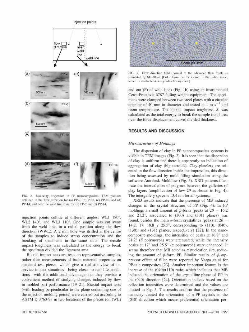
The dispersion of clay in PP nanocomposites systems is
visible in TEM images (Fig. 2). It is seen that the dispersion
of clay is uniform and there is apparently no indication of
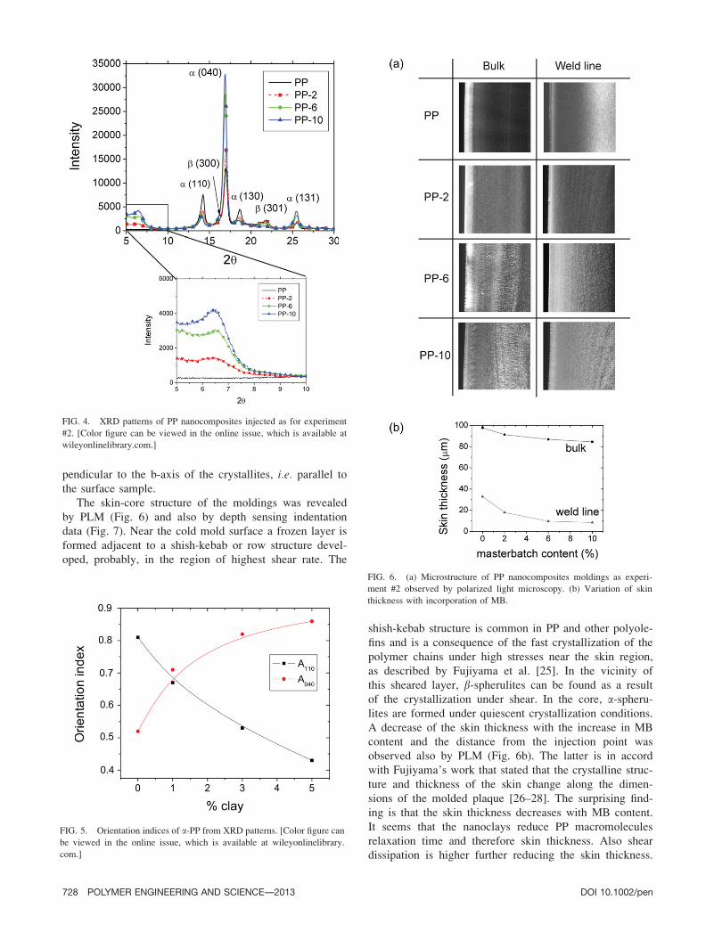
aggregation of clay (big tactoids). Clay platelets are ori-
ented in the flow direction inside the impression, this direc-
tion being assessed by mold filling simulation using the
software Autodesk Moldflow (Fig. 3). XRD patterns illus-
trate the intercalation of polymer between the galleries of
clay layers (amplification of low 2y as shown in Fig. 4).
The intergallery space is 13.4 nm for all systems.
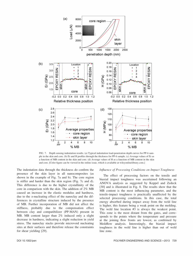
XRD results indicate that the presence of MB induced
changes in the crystal structure of PP (Fig. 4). In PP
moldings a small amount of b-form (peaks at 2y ¼ 16.2
and 21.28, associated to (300) and (301) planes) was
found, besides the main a-form crystallites (peaks at 2y ¼14.2, 17, 18.8 y 25.58, corresponding to (110), (040),
(130), and (131) planes, respectively) [22]. In the nano-
composite moldings, the intensities of peaks at 16.28 and
21.28 (b polymorph) were attenuated, while the intensity
peaks at 178 and 25.58 (a polymorph) were enhanced. It
seems therefore that MB acted as a nucleation site, reduc-
ing the amount of b-form PP. Similar results of b-sup-pressor effect of filler were reported by Varga et al for
PP-talc composites [23]. Another important feature is the
increase of the (040)/(110) ratio, which indicates that MB
induced the orientation of the crystalline-phase of PP in
the (040) direction [24]. Orientation indices based on the
reflection intensities were determined and the values are
plotted in Fig. 5. The results confirm that the presence of
nanoclay caused the orientation of a-PP crystals in the
(040) direction which means preferential orientation per-
FIG. 2. Nanoclay dispersion in PP nanocomposites. TEM pictures
obtained in the flow direction for (a) PP-2, (b) PP-6, (c) PP-10, and (d)
PP-14; and near the weld line zone for (e) PP-2 and (f) PP-14.
FIG. 3. Flow direction field (normal to the advanced flow front) as
simulated by Moldflow. [Color figure can be viewed in the online issue,
which is available at wileyonlinelibrary.com.]
DOI 10.1002/pen POLYMER ENGINEERING AND SCIENCE—-2013 727
pendicular to the b-axis of the crystallites, i.e. parallel tothe surface sample.
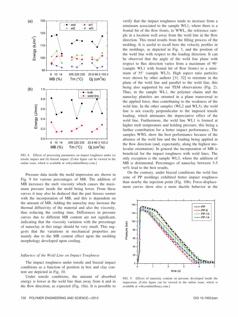
The skin-core structure of the moldings was revealed
by PLM (Fig. 6) and also by depth sensing indentation
data (Fig. 7). Near the cold mold surface a frozen layer is
formed adjacent to a shish-kebab or row structure devel-
oped, probably, in the region of highest shear rate. The
shish-kebab structure is common in PP and other polyole-
fins and is a consequence of the fast crystallization of the
polymer chains under high stresses near the skin region,
as described by Fujiyama et al. [25]. In the vicinity of
this sheared layer, b-spherulites can be found as a result
of the crystallization under shear. In the core, a-spheru-lites are formed under quiescent crystallization conditions.
A decrease of the skin thickness with the increase in MB
content and the distance from the injection point was
observed also by PLM (Fig. 6b). The latter is in accord
with Fujiyama’s work that stated that the crystalline struc-
ture and thickness of the skin change along the dimen-
sions of the molded plaque [26–28]. The surprising find-
ing is that the skin thickness decreases with MB content.
It seems that the nanoclays reduce PP macromolecules
relaxation time and therefore skin thickness. Also shear
dissipation is higher further reducing the skin thickness.
FIG. 5. Orientation indices of a-PP from XRD patterns. [Color figure can
be viewed in the online issue, which is available at wileyonlinelibrary.
com.]
FIG. 4. XRD patterns of PP nanocomposites injected as for experiment
#2. [Color figure can be viewed in the online issue, which is available at
wileyonlinelibrary.com.]
FIG. 6. (a) Microstructure of PP nanocomposites moldings as experi-
ment #2 observed by polarized light microscopy. (b) Variation of skin
thickness with incorporation of MB.
728 POLYMER ENGINEERING AND SCIENCE—-2013 DOI 10.1002/pen
The indentation data through the thickness do confirm the
presence of the skin layer in all nanocomposites (as
shown in the example of Fig. 7a and b). The core region
is stiffer and harder than the skin region (Fig. 7c and d).
This difference is due to the higher crystallinity of the
core in comparison with the skin. The addition of 2% MB
caused an increase in the elastic modulus and hardness,
due to the a-nucleating effect of the nanoclay and the dif-
ferences in crystalline structure induced by the presence
of MB. Further incorporation of MB did not affect the
stiffness, probably due to the compensation effect
between clay and compatibilizer (PP-MAN) present in
MB. MB content larger than 2% induced only a slight
decrease in hardness, indicating a slight reduction in yield
stress. The nanoclay stacks provide microvoid nucleating
sites at their surfaces and therefore release the constraints
for shear yielding [29].
Influence of Processing Conditions on Impact Toughness
The effect of processing factors on the tensile and
biaxial impact toughness was ascertained following an
ANOVA analysis as suggested by Keppel and Zedeck
[30] and is illustrated in Fig. 8. The results show that the
MB content is the most influencing parameter, and thetensile-impact toughness is practically unaffected by theselected processing conditions. In this case, the totalenergy absorbed during impact away from the weld lineis higher, this feature being a weak point on the molding.The weld line location #3 is always the weakest point.This zone is the most distant from the gates, and corre-sponds to the points where the temperature and pressureat the joining flow fronts are lowest, as confirmed byMoldflow analysis. Interestingly, the biaxial impacttoughness in the weld line is higher than out of weldline zone.
FIG. 7. Depth sensing indentation results. (a) Typical indentation load-penetration depth curves for PP-6 sam-
ple in the skin and core. (b) Er and H profiles through the thickness for PP-6 sample. (c) Average values of Er as
a function of MB content in the skin and core. (d) Average values of H as a function of MB content in the skin
and core. [Color figure can be viewed in the online issue, which is available at wileyonlinelibrary.com.]
DOI 10.1002/pen POLYMER ENGINEERING AND SCIENCE—-2013 729
Pressure data inside the mold impression are shown in
Fig. 9 for various percentages of MB. The addition of
MB increases the melt viscosity which causes the maxi-
mum pressure inside the mold being lower. From these
curves it may also be deduced that the part freezes sooner
with the incorporation of MB, and this is dependent on
the amount of MB. Adding the nanoclay may increase the
thermal diffusivity of the material and also the viscosity,
thus reducing the cooling time. Differences in pressure
curves due to different MB content are not significant,
indicating that the viscosity variation with the percentage
of nanoclay in this range should be very small. This sug-
gests that the variations in mechanical properties are
mainly due to the MB content effect upon the molding
morphology developed upon cooling.
Influence of the Weld Line on Impact Toughness
The impact toughness under tensile and biaxial impact
conditions as a function of position in box and clay con-
tent are depicted in Fig. 10.
Under tensile conditions, the amount of absorbed
energy is lower at the weld line than away from it and in
the flow direction, as expected (Fig. 10a). It is possible to
verify that the impact toughness tends to increase from a
minimum associated to the sample WL1, where there is a
frontal hit of the flow fronts, to WWL, the reference sam-
ple in a location well away from the weld line in the flow
direction. This trend results from the filling process of the
molding. It is useful to recall here the velocity profiles in
the moldings, as depicted in Fig. 3, and the position of
the weld line with respect to the loading direction. It can
be observed that the angle of the weld line plane with
respect to flux direction varies from a maximum of 908(sample WL1 with frontal hit of flow fronts) to a mini-
mum of 558 (sample WL3). High aspect ratio particles
were shown by other authors [31, 32] to orientate in the
plane of the weld line and parallel to the weld line, this
being also supported by our TEM observations (Fig. 2).
Thus, in the sample WL1, the polymer chains and the
nanoclay platelets are oriented in a plane transversal to
the applied force, thus contributing to the weakness of the
weld line. In the other samples (WL2 and WL3), the weld
line is not exactly perpendicular to the imposed tensile
loading, which attenuates the depreciative effect of the
weld line. Furthermore, the weld line WL1 is formed at
higher melt temperature and holding pressure, this being a
further contribution for a better impact performance. The
samples WWL show the best performance because of the
absence of the weld line and the loading being applied in
the flow direction (and, expectantly, along the highest mo-
lecular orientation). In general the incorporation of MB is
beneficial for the impact toughness with weld lines. The
only exception is the sample WL3, where the addition of
MB is detrimental. Percentages of nanoclay between 3-5
wt% lead to the best results.
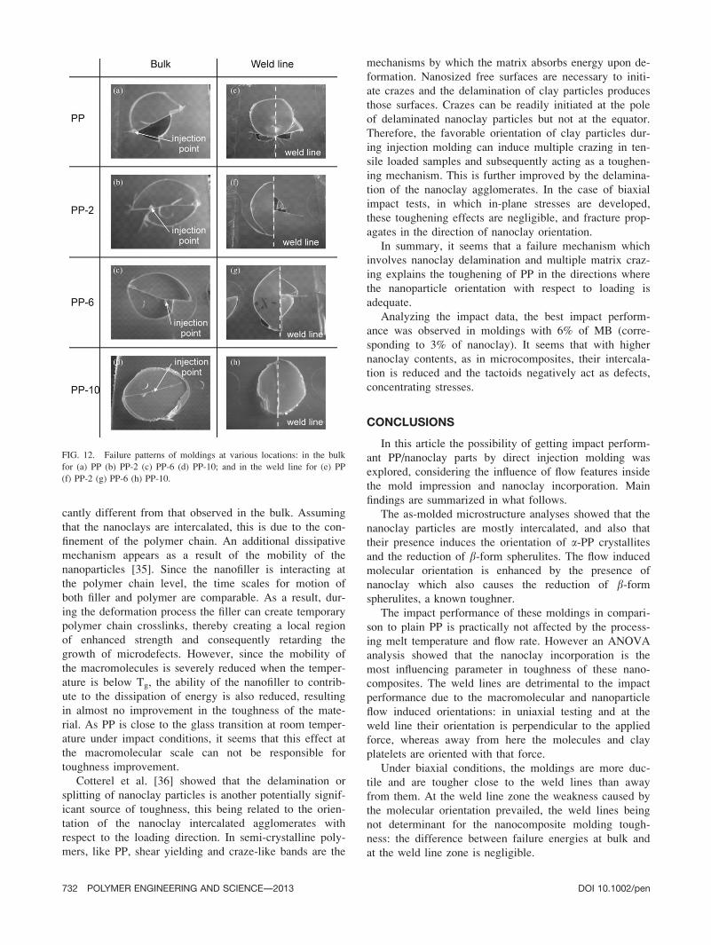
On the contrary, under biaxial conditions the weld line
zone of PP moldings exhibited better impact toughness
than nearby the injection point (Fig. 10b). Force-displace-
ment curves show also a more ductile behavior at the
FIG. 8. Effects of processing parameters on impact toughness under (a)
tensile impact and (b) biaxial impact. [Color figure can be viewed in the
online issue, which is available at wileyonlinelibrary.com.]
FIG. 9. Effects of nanoclay content on pressure developed inside the
impression. [Color figure can be viewed in the online issue, which is
available at wileyonlinelibrary.com.]
730 POLYMER ENGINEERING AND SCIENCE—-2013 DOI 10.1002/pen
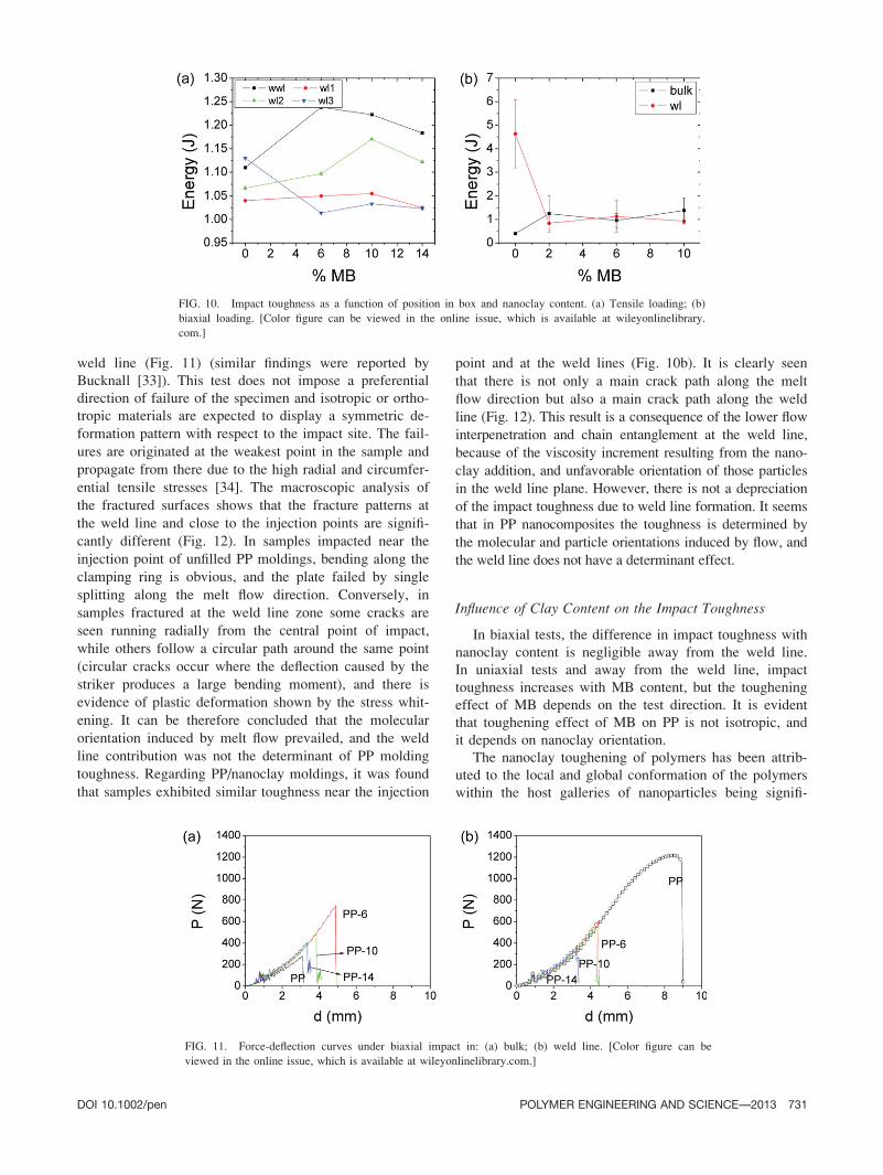
weld line (Fig. 11) (similar findings were reported by
Bucknall [33]). This test does not impose a preferential
direction of failure of the specimen and isotropic or ortho-
tropic materials are expected to display a symmetric de-
formation pattern with respect to the impact site. The fail-
ures are originated at the weakest point in the sample and
propagate from there due to the high radial and circumfer-
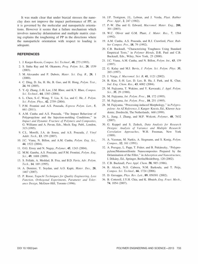
ential tensile stresses [34]. The macroscopic analysis of
the fractured surfaces shows that the fracture patterns at
the weld line and close to the injection points are signifi-
cantly different (Fig. 12). In samples impacted near the
injection point of unfilled PP moldings, bending along the
clamping ring is obvious, and the plate failed by single
splitting along the melt flow direction. Conversely, in
samples fractured at the weld line zone some cracks are
seen running radially from the central point of impact,
while others follow a circular path around the same point
(circular cracks occur where the deflection caused by the
striker produces a large bending moment), and there is
evidence of plastic deformation shown by the stress whit-
ening. It can be therefore concluded that the molecular
orientation induced by melt flow prevailed, and the weld
line contribution was not the determinant of PP molding
toughness. Regarding PP/nanoclay moldings, it was found
that samples exhibited similar toughness near the injection
point and at the weld lines (Fig. 10b). It is clearly seen
that there is not only a main crack path along the melt
flow direction but also a main crack path along the weld
line (Fig. 12). This result is a consequence of the lower flow
interpenetration and chain entanglement at the weld line,
because of the viscosity increment resulting from the nano-
clay addition, and unfavorable orientation of those particles
in the weld line plane. However, there is not a depreciation
of the impact toughness due to weld line formation. It seems
that in PP nanocomposites the toughness is determined by
the molecular and particle orientations induced by flow, and
the weld line does not have a determinant effect.
Influence of Clay Content on the Impact Toughness
In biaxial tests, the difference in impact toughness with
nanoclay content is negligible away from the weld line.
In uniaxial tests and away from the weld line, impact
toughness increases with MB content, but the toughening
effect of MB depends on the test direction. It is evident
that toughening effect of MB on PP is not isotropic, and
it depends on nanoclay orientation.
The nanoclay toughening of polymers has been attrib-
uted to the local and global conformation of the polymers
within the host galleries of nanoparticles being signifi-
FIG. 10. Impact toughness as a function of position in box and nanoclay content. (a) Tensile loading; (b)
biaxial loading. [Color figure can be viewed in the online issue, which is available at wileyonlinelibrary.
com.]
FIG. 11. Force-deflection curves under biaxial impact in: (a) bulk; (b) weld line. [Color figure can be
viewed in the online issue, which is available at wileyonlinelibrary.com.]
DOI 10.1002/pen POLYMER ENGINEERING AND SCIENCE—-2013 731
cantly different from that observed in the bulk. Assuming
that the nanoclays are intercalated, this is due to the con-
finement of the polymer chain. An additional dissipative
mechanism appears as a result of the mobility of the
nanoparticles [35]. Since the nanofiller is interacting at
the polymer chain level, the time scales for motion of
both filler and polymer are comparable. As a result, dur-
ing the deformation process the filler can create temporary
polymer chain crosslinks, thereby creating a local region
of enhanced strength and consequently retarding the
growth of microdefects. However, since the mobility of
the macromolecules is severely reduced when the temper-
ature is below Tg, the ability of the nanofiller to contrib-
ute to the dissipation of energy is also reduced, resulting
in almost no improvement in the toughness of the mate-
rial. As PP is close to the glass transition at room temper-
ature under impact conditions, it seems that this effect at
the macromolecular scale can not be responsible for
toughness improvement.
Cotterel et al. [36] showed that the delamination or
splitting of nanoclay particles is another potentially signif-
icant source of toughness, this being related to the orien-
tation of the nanoclay intercalated agglomerates with
respect to the loading direction. In semi-crystalline poly-
mers, like PP, shear yielding and craze-like bands are the
mechanisms by which the matrix absorbs energy upon de-
formation. Nanosized free surfaces are necessary to initi-
ate crazes and the delamination of clay particles produces
those surfaces. Crazes can be readily initiated at the pole
of delaminated nanoclay particles but not at the equator.
Therefore, the favorable orientation of clay particles dur-
ing injection molding can induce multiple crazing in ten-
sile loaded samples and subsequently acting as a toughen-
ing mechanism. This is further improved by the delamina-
tion of the nanoclay agglomerates. In the case of biaxial
impact tests, in which in-plane stresses are developed,
these toughening effects are negligible, and fracture prop-
agates in the direction of nanoclay orientation.
In summary, it seems that a failure mechanism which
involves nanoclay delamination and multiple matrix craz-
ing explains the toughening of PP in the directions where
the nanoparticle orientation with respect to loading is
adequate.
Analyzing the impact data, the best impact perform-
ance was observed in moldings with 6% of MB (corre-
sponding to 3% of nanoclay). It seems that with higher
nanoclay contents, as in microcomposites, their intercala-
tion is reduced and the tactoids negatively act as defects,
concentrating stresses.
CONCLUSIONS
In this article the possibility of getting impact perform-
ant PP/nanoclay parts by direct injection molding was
explored, considering the influence of flow features inside
the mold impression and nanoclay incorporation. Main
findings are summarized in what follows.
The as-molded microstructure analyses showed that the
nanoclay particles are mostly intercalated, and also that
their presence induces the orientation of a-PP crystallites
and the reduction of b-form spherulites. The flow induced
molecular orientation is enhanced by the presence of
nanoclay which also causes the reduction of b-formspherulites, a known toughner.
The impact performance of these moldings in compari-
son to plain PP is practically not affected by the process-
ing melt temperature and flow rate. However an ANOVA
analysis showed that the nanoclay incorporation is the
most influencing parameter in toughness of these nano-
composites. The weld lines are detrimental to the impact
performance due to the macromolecular and nanoparticle
flow induced orientations: in uniaxial testing and at the
weld line their orientation is perpendicular to the applied
force, whereas away from here the molecules and clay
platelets are oriented with that force.
Under biaxial conditions, the moldings are more duc-
tile and are tougher close to the weld lines than away
from them. At the weld line zone the weakness caused by
the molecular orientation prevailed, the weld lines being
not determinant for the nanocomposite molding tough-
ness: the difference between failure energies at bulk and
at the weld line zone is negligible.
FIG. 12. Failure patterns of moldings at various locations: in the bulk
for (a) PP (b) PP-2 (c) PP-6 (d) PP-10; and in the weld line for (e) PP
(f) PP-2 (g) PP-6 (h) PP-10.
732 POLYMER ENGINEERING AND SCIENCE—-2013 DOI 10.1002/pen
It was made clear that under biaxial stresses the nano-
clay does not improve the impact performance of PP, as
it is governed by the molecular and nanoparticle orienta-
tions. However it seems that a failure mechanism which
involves nanoclay delamination and multiple matrix craz-
ing explains the toughening of PP in the directions where
the nanoparticle orientation with respect to loading is
adequate.
REFERENCES
1. J. Karger-Kocsis, Compos. Sci. Technol., 48, 273 (1993).
2. S. Sinha Ray and M. Okamoto, Prog. Polym. Sci., 28, 1539(2003).
3. M. Alexandre and P. Dubois, Mater. Sci. Eng. R., 28, 1
(2000).
4. C. Ding, D. Jia, H. He, B. Guo, and H. Hong, Polym. Test.,24, 94 (2005).
5. Y.-Q. Zhang, J.-H. Lee, J.M. Rhee, and K.Y. Rhee, Compos.Sci. Technol., 64, 1383 (2004).
6. L. Chen, S.-C. Wong, T. Liu, X. Lu, and C. He, J. Polym.Sci. Polym. Phys., 42, 2759 (2004).
7. P.M. Frontini and A.S. Pouzada, Express Polym. Lett., 5,
661 (2011).
8. A.M. Cunha and A.S. Pouzada, ‘‘The Impact Behaviour of
Polypropylene and the Injection-molding Conditions,’’ in
Impact and Dynamic Fracture of Polymers and Composites,G. Williams and A. Pavan, Eds., Mech. Eng. Publ., London,
315 (1995).
9. C.L. Morelli, J.A. de Sousa, and A.S. Pouzada, J. VinylAddit. Tech., 13, 159 (2007).
10. J.C. Viana, N. Billon, and A.M. Cunha, Polym. Eng. Sci.,44, 1522 (2004).
11. O.G. Ersoy and N. Nugay, Polymer, 45, 1243 (2004).
12. M.M. Gamba, A.S. Pouzada, and P.M. Frontini, Polym. Eng.Sci., 49, 1688 (2009).
13. S. Fellahi, A. Meddad, B. Fisa, and B.D. Favis, Adv. Polym.Tech., 14, 169 (1995).
14. A. Demirer, Y. Soydan, and A.O. Kapti, Mater. Des., 28,1467 (2007).
15. P. Rosse, Taguchi Techniques for Quality Engineering, LossFunction, Orthogonal Experiments, Parameter and Toler-ance Design, McGraw-Hill, Toronto (1996).
16. J.P. Trotignon, J.L. Lebrun, and J. Verdu, Plast. RubberProc. Appl., 2, 247 (1982).
17. P.-W. Zhu and G. Edward, Macromol. Mater. Eng., 288,
301 (2003).
18. W.C. Oliver and G.M. Pharr, J. Mater. Res., 7, 1564
(1992).
19. A.M. Cunha, A.S. Pouzada, and R.J. Crawford, Plast. Rub-ber Compos. Pro., 18, 79 (1992).
20. C.B. Bucknall, ‘‘Characterizing Toughness Using Standard
Empirical Tests,’’ in Polymer Blends, D.R. Paul and C.B.
Bucknall, Eds., Wiley, New York, 25 (2000).
21. J.C. Viana, A.M. Cunha, and N. Billon, Polym. Int., 43, 159(1997).
22. G. Kalay and M.J. Bevis, J. Polym. Sci. Polym. Phys. 35,265 (1997).
23. J. Varga, J. Macromol. Sci. B, 41, 1121 (2002).
24. B. Kim, S.-H. Lee, D. Lee, B. Ha, J. Park, and K. Char,
Ind. Eng. Chem. Res., 43, 6082 (2004).
25. M. Fujiyama, T. Wakino, and Y. Kawasaki, J. Appl. Polym.Sci., 35, 29 (1988).
26. M. Fujiyama, Int. Polym. Proc., 10, 172 (1995).
27. M. Fujiyama, Int. Polym. Proc., 10, 251 (1995).
28. M. Fujiyama, ‘‘Processing-induced Morphology,’’ in Polypro-pylene: An AZ Reference, J. Karger- Kocsis, Ed., Kluwer Aca-
demic, Dordrecht, The Netherlands, 668 (1999).
29. L. Jiang, J. Zhang, and M.P. Wolcott, Polymer, 48, 7632
(2007).
30. G. Keppel and S. Zedeck, Data Analysis for ResearchDesigns: Analysis of Variance and Multiple Research/Correlation Approaches, W.H. Freeman, New York
(1989).
31. A. Vaxman, M. Narkis, A. Siegmann, and S. Kenig, Polym.Compos., 12, 161 (1991).
32. A. Pozsgay, L. Papp, T. Frater, and B. Pukanszky, ‘‘Polypro-
pylene/Montmorillonite Nanocomposites Prepared by the
Delamination of the Filler,’’ in Adsorption and Nanostructure,
I. Dekany, Ed., Springer, Berlin/Heidelberg, 120 (2002).
33. C.B. Bucknall, Pure Appl. Chem. 58, 985 (1986).
34. B. Alcock, N.O. Cabrera, N.M. Barkoula, and T. Peijs,
Compos. Sci. Technol., 66, 1724 (2006).
35. D. Gersappe, Phys. Rev. Lett., 89, 058301 (2002).
36. B. Cotterell, J.Y.H. Chia, and K. Hbaieb, Eng. Fract. Mech.,74, 1054 (2007).
DOI 10.1002/pen POLYMER ENGINEERING AND SCIENCE—-2013 733