Embed Size (px)
Citation preview

Up and Running with Autodesk Inventor Professional
Simulation in 90 Minutes! Wasim Younis - Author of Up and Running Inventor Professional Simulation books
MA2038 - This class will present a workflow for effectively using the simulation tools in Autodesk®
Inventor® Professional software. After this class, you will be able to confidently apply this technology to your own workplace. The class highlights top Inventor simulation tips, ways to solve real-life design problems with Inventor Professional simulation tools, and additional guidance to make you an expert in only 90 minutes.
Learning Objectives
At the end of this class, you will be able to:
Describe best practices for using Inventor Simulation tools
List tips for using Inventor Simulation tools
Solve real-life design problems
Optimize your designs
About the Speaker
Wasim Younis (UK) is an Inventor Simulation consultant and trainer with more than 15 years of experience in the manufacturing field. He has been involved with Inventor Simulation software when it was first introduced, and is well-known throughout the Inventor Simulation community. Wasim contributes articles, whitepapers, tips and tricks and tutorials to various forums. He regularly authors simulation Tips and Tricks articles on his own Virtual Reality blog (http://vrblog.info) - a blog dedicated to the Autodesk Inventor Simulation Community. He also runs a dedicated forum for simulation users on LinkedIn – Up and Running with Autodesk Inventor Simulation Wasim has a bachelor’s degree in Mechanical Engineering from the University of Bradford and a master’s degree in CAE from Staffordshire University. Currently he is a Senior Simulation Consultant @ Symetri (http://www.symetri.co.uk) – one of the largest Platinum Autodesk manufacturing value added reseller in Northern Europe.

Up and Running with Autodesk Inventor Professional Simulation in 90 Minutes
2
Introduction I welcome you all to my lecture at Autodesk University 2012 and I hope you will find it stimulating. In my
years of training and working with Inventor users. I have seen many who were struggling to make the
most of Inventor's tremendous and powerful Simulation technology, and to integrate it in the design
process. In my opinion, one significant reason for this struggle is the lack of confidence in applying
Inventor Simulation to the user's own product and development environment. As a result of this lack of
confidence designer/engineers continue to produce products which are overdesigned. It is my aim in this
lecture to arm you with key knowledge to help you apply this technology to your own design, hopefully
with some confidence.
Inventor Simulation can perform three types of analyses, as illustrated below.
1. Dynamic Simulation - allows you to simulate mechanisms and determine forces, reactions etc
2. Stress Analysis - allows you analyze designs for strength and help to reduce weight
3. Frame Analysis - allows you analyze large scale structures
4. Optimization - allows to optimize designs - This is cloud based.
Dynamic Simulation Allows the designer to convert assembly constraints automatically to mechanical joints, provides the
capability to apply external forces including
gravity, and allows the effects of contact
friction, damping and inertia to be taken into
account. As a result of this, Dynamic
Simulation provides reaction forces,
velocities, acceleration and much more. With
this information the designer can re-use
reaction forces automatically to perform
finite element analysis, hence reducing risks
and assumptions. Ultimately all this
information helps the designers to build an
optimum product, as illustrated.

Up and Running with Autodesk Inventor Professional Simulation in 90 Minutes
3
Dynamic Simulation Workflow
The process of creating a Dynamic Simulation study involves four core steps.
The most time consuming process with the Dynamic Simulation Workflow is step 2 – creating joints – and this can be
greatly affected by Step 1 – grouping components. Furthermore Step 2: The process of creating joints can be broken
down into 2 stages as discussed below
Stage 1 – Create standard joints.
Stage 2 – Create nonstandard joints.
Stage 1 - there are three options to create standard joints, and, again each
has its own advantages and disadvantages.
Option 1 – Use Automatically Convert Constraints to Standard Joints.
Advantage
– This is by far the quickest way to create joints.
1. With 2012 version you now have the option to retain joints created once you switch of Automatically Convert Constraints to Standard Joints tool, and then carry on creating joints using either option 2 or 3.
Disadvantages
– Can be tedious to go through all joints converted for a large assembly. – Cannot repair redundancies within the Simulation environment. – Cannot create Standard joints with the Simulation environment, with the
exception of Spatial joint.
Step 1
Step 2
GROUP together all components and assemblies with no
relative motion between them
CREATE JOINTS between components that have relative
motion between them
CREATE ENVIRONMENTAL CONDITIONS
to simulate reality
ANALYZE RESULTS
Step 3
Step 4
Up and Running with Autodesk Inventor Professional Simulation in 90 Minutes
4
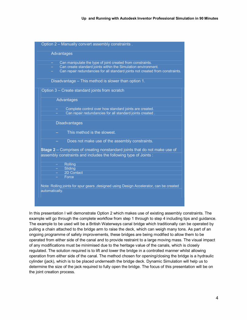
In this presentation I will demonstrate Option 2 which makes use of existing assembly constraints. The
example will go through the complete workflow from step 1 through to step 4 including tips and guidance.
The example to be used will be a British Waterways canal bridge which traditionally can be operated by
pulling a chain attached to the bridge arm to raise the deck, which can weigh many tons. As part of an
ongoing programme of safety improvements, these bridges are being modified to allow them to be
operated from either side of the canal and to provide restraint to a large moving mass. The visual impact
of any modifications must be minimised due to the heritage value of the canals, which is closely
regulated. The solution required is to lift and lower the bridge in a controlled manner whilst allowing
operation from either side of the canal. The method chosen for opening/closing the bridge is a hydraulic
cylinder (jack), which is to be placed underneath the bridge deck. Dynamic Simulation will help us to
determine the size of the jack required to fully open the bridge. The focus of this presentation will be on
the joint creation process.
Option 2 – Manually convert assembly constraints .
Advantages
– Can manipulate the type of joint created from constraints. – Can create standard joints within the Simulation environment. – Can repair redundancies for all standard joints not created from constraints.
Disadvantage – This method is slower than option 1.
Option 3 – Create standard joints from scratch
Advantages
– Complete control over how standard joints are created. – Can repair redundancies for all standard joints created .
Disadvantages
– This method is the slowest.
– Does not make use of the assembly constraints.
Stage 2 – Comprises of creating nonstandard joints that do not make use of
assembly constraints and includes the following type of Joints :
– Rolling – Sliding – 2D Contact – Force
Note: Rolling joints for spur gears ,designed using Design Accelerator, can be created
automatically.

Up and Running with Autodesk Inventor Professional Simulation in 90 Minutes
5
Stress Analysis Stress analysis is an engineering discipline that determines the stress in materials and structures
subjected to static or dynamic forces or loads. The aim of the analysis is usually to determine whether the
element or collection of elements, usually referred to as a structure or component, can safely withstand
the specified forces and loads. This is achieved when the determined stress from the applied force(s) is
less than the yield strength the material is known to be able to withstand. This stress relationship is
commonly referred to as factor of safety (FOS) and is used in many analyses as an indicator of success
or failure in analysis.
𝐅𝐚𝐜𝐭𝐨𝐫 𝐨𝐟 𝐒𝐚𝐟𝐞𝐭𝐲 = Yield Stress
Calculated Stress =
Ultimate Stress
Calculated Stress
Stress Analysis Workflow
The process of creating a Stress Analysis study involves four core steps
Step 1
Step 2
IDEALIZATION – Simplify Geometry, including setting up the
analysis
BOUNDARY CONDITIONS – Apply constraints loads
including defining contacts and mesh setting
including exporting loads from simulation
RUN SIMULATION AND ANALYZE– Analysis and
interpretation of results, via various tools to determine FOS
including convergence of results
OPTIMIZATION –If needed modify geometry to meet design
goals including reducing weight etc
including changing original material
Step 3
Step 4
Up and Running with Autodesk Inventor Professional Simulation in 90 Minutes
6
In Stress Analysis, in my opinion, the most important step is idealization. This greatly has an impact on
the speed and accuracy of the results. The second most important aspect of stress analysis is the
interpretation of result, including how to overcome stress singularities, briefly mentioned below and further
discussed within lecture.
Stress Singularities
Stress Singularities are a major concern when analyzing results as they considerably distort results. They
are also a main cause for non-convergence of results. So, the first question is -what is stress singularity?
This can be best explained by the following example.
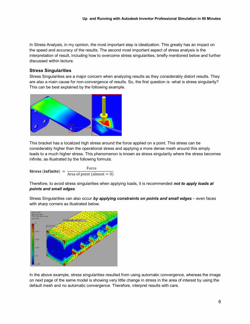
This bracket has a localized high stress around the force applied on a point. This stress can be
considerably higher than the operational stress and applying a more dense mesh around this simply
leads to a much higher stress. This phenomenon is known as stress singularity where the stress becomes
infinite, as illustrated by the following formula:
𝐒𝐭𝐫𝐞𝐬𝐬 (𝐢𝐧𝐟𝐢𝐧𝐢𝐭𝐞) = Force
Area of point (almost = 0)
Therefore, to avoid stress singularities when applying loads, it is recommended not to apply loads at
points and small edges.
Stress Singularities can also occur by applying constraints on points and small edges – even faces
with sharp corners as illustrated below.
In the above example, stress singularities resulted from using automatic convergence, whereas the image
on next page of the same model is showing very little change in stress in the area of interest by using the
default mesh and no automatic convergence. Therefore, interpret results with care.

Up and Running with Autodesk Inventor Professional Simulation in 90 Minutes
7
Finally, another cause of stress singularity is over-simplification of components. Let’s look at the
following example.
In this example, the fillets have been removed to simplify the analysis; however, when using automatic
convergence, the maximum stress value does not converge as all the stress is concentrated around the
edge, as shown. In this scenario it would advisable to unsuppress the fillets (or, in cases when fillets are
not modeled, use fillets to distribute loads).
So, in brief to avoid stress singularities within models is to:
1. Avoid applying loads on points and small edges.
2. Avoid restraining faces with sharp corners, including points and small edges.
3. Apply fillets and chamfers to evenly distribute loads.

Up and Running with Autodesk Inventor Professional Simulation in 90 Minutes
8
In this section of the presentation I will use the following traffic sign post example, as illustrated below.
The purpose of the analysis is to determine whether the structure is strong enough to withstand the wind
speeds exerted on the structure and LED panel. The wind speeds will be calculated using the following
formula (googled on world wide web)
𝑭𝒐𝒓𝒄𝒆 𝑭 = 𝑨 𝒙 𝑷 𝒙 𝑪𝒅 𝒂𝒏𝒅 𝑷 = 𝟎.𝟏𝟐𝟐𝟓𝟕 𝒙 𝑽𝟐
Where:
F is force in Newtons (N)
A is the cross section of the LED display panel in Meters (approx 2m2)
P is the pressure in Pascals (N/m)
V is the wind speed in (Mph)
Cd is the drag coefficient ( 2 to be used for rectangular flat areas)
For a wind speed of 25 and 50 mph we get the total force's to be;
𝑷 = 𝟎.𝟏𝟐𝟐𝟓𝟕 𝒙 𝟐𝟓𝟐 = 76.6 (25mph) 𝑷 = 𝟎.𝟏𝟐𝟐𝟓𝟕 𝒙 𝟓𝟎𝟐 = 306.4 (50mph)
𝑭𝒐𝒓𝒄𝒆 𝑭 = 𝟐 𝒙 𝟕𝟔.𝟔 𝒙 𝟐 = 𝟑𝟎𝟔𝐍 𝑭𝒐𝒓𝒄𝒆 𝑭 = 𝟐 𝒙 𝟑𝟎𝟔.𝟒 𝒙 𝟐 = 𝟏𝟐𝟐𝟓.𝟕𝐍

Up and Running with Autodesk Inventor Professional Simulation in 90 Minutes
9
Frame Analysis Frame Analysis is normally associated with analyzing large structures mainly comprising of uniform cross-
section channels/frames. Typical examples include bridges, structural platforms, towers etc. Some
examples are illustrated below.
Frame Analysis, within Autodesk Inventor Simulation, allows the user to define criteria for static and
modal analysis, including pre-stressing. In addition, Frame Analysis uses beam elements instead of the
3D tetrahedron and thin elements, that are used within the Stress Analysis environment. This significantly
helps to speed up analysis times within frame analysis.
Frame Analysis Workflow
The process of creating an analysis (both stress and modal) involves four core steps:
Step 1
Step 2
IDEALIZATION – Create main structures using Content
Centre and/or Frame Generator
BOUNDARY CONDITIONS – Apply constraints loads
including setting up rigid links.
including exporting loads from simulation
RUN SIMULATION AND ANALYZE Analysis and
interpretation of results, via various tools.
OPTIMIZATION – If needed customize materials and beam
properties to create an optimum design
Step 3
Step 4

Up and Running with Autodesk Inventor Professional Simulation in 90 Minutes
10
The following tube example demonstrates the benefits of using frame analysis over stress analysis when
analyzing structures ( with length to thickness ratio typically 100 to 1) with uniform cross sectional
properties.
Initially we will determine theoretical results for the tube. We will fix the tube at one end and apply a load
of 100N at the other end
Tube data to be used is as follows;
Length = 100mm
Diameter = 10mm
Thickness = 0.5mm
Material = Mild Steel
Using the classical Bending Stress Equation:
𝑴
𝑰=𝝈
𝒚=𝑬
𝑹
we can determine maximum stress (at fixed end)
𝑴max = Total length x Load = 100 x 100 = 10,000Nmm
𝒚 = 5mm
𝑰 =𝜋
64( ∅outside
4 - ∅inside
4 ) =
𝜋
64( 10
4 - 9
4 ) = 168.8mm
4
𝝈𝒎𝒂𝒙 =𝑀𝑦
𝐼(10000 𝑥 5)/168.8 = 296 N/mm
2

Up and Running with Autodesk Inventor Professional Simulation in 90 Minutes
11
Stress Analysis Results - using 4 noded tetrahedron elements - 316 N/mm2 or (316 MPa)
% difference = 6.75. Although this value is
acceptable (within 10%) the difference is
primarily due to stress singularities as
refining the mesh around the high stress
area will result in higher stresses. This is
discussed later in the chapter
Stress Analysis Results - using 4 noded shell elements - 287 N/mm2
% difference = 3%. This is almost 50% better
than using tetrahedron elements.
Frame Analysis Results - using beam elements - 296 N/mm2
% difference = 0%. This is because frame
analysis does not have the stress singularity
issues as in stress analysis.

Up and Running with Autodesk Inventor Professional Simulation in 90 Minutes
12
In this final section of the presentation I will use the following example of a skid, commonly used within
the offshore industry worldwide.
In this example the main requirements is to satisfy DNV standards using Frame Analysis including 4 point
and 2 point lift. This is typical testing's for offshore containers/baskets (commonly referred to as skids). In
the presentation I will illustrate how to simulate skids with slings to get a more realistic behavior of skids
and more importantly yielding in more accurate results.

Up and Running with Autodesk Inventor Professional Simulation in 90 Minutes
13
Further Reading The material in this handout and lecture is based on my Up and Running with Autodesk Inventor
Professional Series. The book's cover all three simulations in a lot more depth with guidance and tips
throughout the books. The following books are available from Amazon worldwide.
http://www.amazon.com/s/ref=nb_sb_noss?url=search-alias%3Daps&field keywords=wasim+younis+autodesk
Additional Resources On LinkedIn there is a dedicated support forum for Inventor Simulation Users around the world. Here you
can post any question on Inventor Simulation and get help
from fellow peers from around the world, including myself.
The Support forum is named Up and Running with
Autodesk Inventor Simulation. To join the forum you first
have to sign up to LinkedIn, which is free.
http://www.linkedin.com/groups?home=&gid=2061026&trk=anet_ug_hm
In addition the support forum there is also a dedicated
simulation blog called Virtual Reality again hosted by me.
This blog is also one of places where you can download
the dataset to go with the books, mentioned earlier in the
further reading section.
http://vrblog.info