Embed Size (px)
Citation preview

training that fi ts your needsMindShare recognizes and addresses your company’s technical training issues with:
• Scalable cost training • Customizable training options • Reducing time away from work• Just-in-time training • Overview and advanced topic courses • Training delivered effectively globally• Training in a classroom, at your cubicle or home offi ce • Concurrently delivered multiple-site training
bringing lifeto knowledge. real-world tech training put into practice worldwide real-world tech training put into practice worldwide real-world tech training put into practice worldwide real-world tech training put into practice worldwide
Are your company’s technical training needs being addressed in the most effective manner?
MindShare has over 25 years experience in conducting technical training on cutting-edge technologies. We understand the challenges companies have when searching for quality, effective training which reduces the students’ time away from work and provides cost-effective alternatives. MindShare offers many fl exible solutions to meet those needs. Our courses are taught by highly-skilled, enthusiastic, knowledgeable and experienced instructors. We bring life to knowledge through a wide variety of learning methods and delivery options.
2 PCI Express 2.0 ®
2 Intel Core 2 Processor Architecture
2 AMD Opteron Processor Architecture
2 Intel 64 and IA-32 Software Architecture
2 Intel PC and Chipset Architecture
2 PC Virtualization
2 USB 2.0
2 Wireless USB
2 Serial ATA (SATA)
2 Serial Attached SCSI (SAS)
2 DDR2/DDR3 DRAM Technology
2 PC BIOS Firmware
2 High-Speed Design
2 Windows Internals and Drivers
2 Linux Fundamentals
... and many more.
All courses can be customized to meet your group’s needs. Detailed course outlines can be found at www.mindshare.com
world-class technical training
MindShare training courses expand your technical skillset
*PCI Express ® is a registered trademark of the PCISIG*PCI Express ® is a registered trademark of the PCISIG

www.mindshare.com 4285 SLASH PINE DRIVE COLORADO SPRINGS, CO 80908 USA M 1.602.617.1123 O 1.800.633.1440 [email protected]
Engage MindShareHave knowledge that you want to bring to life? MindShare will work with you to “Bring Your Knowledge to Life.” Engage us to transform your knowledge and design courses that can be delivered in classroom or virtual class-room settings, create online eLearning modules, or publish a book that you author.
We are proud to be the preferred training provider at an extensive list of clients that include:ADAPTEC • AMD • AGILENT TECHNOLOGIES • APPLE • BROADCOM • CADENCE • CRAY • CISCO • DELL • FREESCALE
GENERAL DYNAMICS • HP • IBM • KODAK • LSI LOGIC • MOTOROLA • MICROSOFT • NASA • NATIONAL SEMICONDUCTOR
NETAPP • NOKIA • NVIDIA • PLX TECHNOLOGY • QLOGIC • SIEMENS • SUN MICROSYSTEMS SYNOPSYS • TI • UNISYS
Classroom Training
Invite MindShare to train you in-house, or sign-up to attend one of our many public classes held throughout the year and around the world. No more boring classes, the ‘MindShare Experience‘ issure to keep you engaged.
Virtual Classroom Training
The majority of our courses live over the web in an inter-active environment with WebEx and a phone bridge. We deliver training cost-effectively across multiple sites and time zones. Imagine being trained in your cubicle or home offi ce and avoiding the hassle of travel. Contact us to attend one of our public virtual classes.
eLearning Module Training
MindShare is also an eLearning company. Our growing list of interactive eLearning modules include:
• Intro to Virtualization Technology
• Intro to IO Virtualization
• Intro to PCI Express 2.0 Updates
• PCI Express 2.0
• USB 2.0
• AMD Opteron Processor Architecture
• Virtualization Technology ...and more
MindShare Press
Purchase our books and eBooks or publish your own content through us. MindShare has authored over 25 books and the listis growing. Let us help make your book project a successful one.
MindShare Learning Options
MindShare Classroom
MindShare Virtual Classroom
MindShare eLearning
MindShare Press
In-House Training
Public Training
Virtual In-House Training
Virtual Public Training
Intro eLearning Modules
Comprehensive eLearning Modules
Books
eBooks
USBSystem
Architecture(USB 2.0)
MINDSHARE, INC.
Don Anderson
ADDISON-WESLEY DEVELOPER’S PRESS
Reading, Massachusetts • Harlow, England • Menlo Park, California
Berkeley, California • Don Mills, Ontario • Sydney
Bonn • Amsterdam • Tokyo • Mexico City

Many of the designations used by manufacturers and sellers to distinguish their products are claimed as trademarks. Where those designators appear in this book, and Addison-Wesley was aware of the trademark claim, the designations have been printed in initial capital letters or all capital letters.
The authors and publishers have taken care in preparation of this book, but make no expressed or implied warranty of any kind and assume no responsibility for errors or omissions. No liability is assumed for incidental or consequential damages in connection with or arising out of the use of the information or programs contained herein.
Library of Congress Cataloging-in-Publication Data
ISBN: 0-201-46137-4
Copyright ©2001 by MindShare, Inc.
All rights reserved. No part of this publication may be reproduced, stored in a retrieval system, or transmitted, in any form or by any means, electronic, mechanical, photocopying, recording, or otherwise, without the prior written permission of the publisher. Printed in the United States of America. Published simultaneously in Canada.
Sponsoring Editor: Project Manager: Cover Design: Set in 10 point Palatino by MindShare, Inc.
1 2 3 4 5 6 7 8 9-MA-999897First Printing, March, 2001
Addison-Wesley books available for bulk purchases by corporations, institutions, and other orga-nizations. For more information please contact the Corporate, Government, and Special Sales Department at (800) 238-9682.
Find A-W Developer’s Press on the World-Wide Web at:http://www.awl.com/devpress/
Contents
About This BookThe MindShare Architecture Series ....................................................................................... 1Cautionary Note ......................................................................................................................... 2Specifications This Book is Based On ................................................................................... 3Organization of This Book....................................................................................................... 3
Part One: Overview of USB 2.0................................................................................... 3Part Two: Low- & Full-Speed Device Operation ..................................................... 4Part III: High-Speed Device Operation...................................................................... 5Part IV: USB 2.0 Hub Operation with LS/FS/HS Devices ..................................... 5Part VI: USB Software Overview................................................................................ 6Appendices .................................................................................................................... 7
Who Should Read this Book .................................................................................................... 7Prerequisite Knowledge ........................................................................................................... 7Documentation Conventions ................................................................................................... 8
Hexadecimal Notation ........................................................................................................ 8Binary Notation.................................................................................................................... 8Decimal Notation ................................................................................................................. 8Bits Versus Byte Notation ................................................................................................... 8
Identification of Bit Fields (logical groups of bits orsignals) ......................................................................................................................................... 9Visit Our Web Page ................................................................................................................... 9We Want Your Feedback........................................................................................................... 9
Part One Overview of USB 2.0
Chapter 1: Design Goals of USBShortcomings of the Original PC I/O Paradigm ................................................................ 13
Limited System Resources ................................................................................................ 14Interrupts ..................................................................................................................... 15I/O Addresses ............................................................................................................. 16Non-shareable Interfaces ........................................................................................... 16
End User Concerns ............................................................................................................ 16Cable Crazed ............................................................................................................... 17Installation and Configuration of Expansion Cards.............................................. 17No Hot Attachment of Peripherals .......................................................................... 17
Cost ...................................................................................................................................... 18The USB Paradigm................................................................................................................... 18
Enhanced System Performance........................................................................................ 19Hot Plug and Play Support .............................................................................................. 20
v
Contents
Expandability...................................................................................................................... 20Legacy Hardware/Software Support ............................................................................. 20Low Cost ............................................................................................................................. 21Summary of Key USB Features........................................................................................ 23
How to Get the USB Specifications...................................................................................... 24
Chapter 2: The Big PictureOverview.................................................................................................................................... 25USB 1.x Systems and Devices ................................................................................................ 28
Low-Speed and Full-Speed Devices................................................................................ 28How Transactions Are Generated................................................................................... 30
What the Descriptors Contain................................................................................... 30How the Transfer Descriptors Are Fetched ............................................................ 30Frame Generation ....................................................................................................... 33
Sharing the Bus................................................................................................................... 34Bandwidth Consideration Summary .............................................................................. 34
2.0 Systems and Devices ......................................................................................................... 37Low-Speed and Full-Speed Devices in a 2.0 System .................................................... 38
Example 2.0 Host Controller Support for LS/FS Devices .................................... 40High-Speed Devices in a 2.0 System ............................................................................... 41
High-Speed Devices Attached to 1.x Ports ............................................................. 41High-Speed Transactions and Microframe Generation ........................................ 42
High-Speed Bandwidth Summary .................................................................................. 42The Players ................................................................................................................................ 44
USB Client Drivers ............................................................................................................. 45USB Bus Driver................................................................................................................... 46USB Host Controller Driver ............................................................................................. 46USB Host Controller/Root Hub ...................................................................................... 47
The Host Controller.................................................................................................... 47The Root Hub .............................................................................................................. 48
USB Hubs ........................................................................................................................... 49Hub Controller ............................................................................................................ 51Hub Repeater............................................................................................................... 52Hub’s Role in Configuration ..................................................................................... 53
USB Devices ........................................................................................................................ 53High-Speed Devices ................................................................................................... 53Full-Speed Devices ..................................................................................................... 53Low-Speed Devices .................................................................................................... 53
USB Communications Model ................................................................................................ 54Communications Flow ...................................................................................................... 54Transfers, IRPs, Frames, and Packets.............................................................................. 55
Transfers....................................................................................................................... 55
vi
Contents
The USB Driver, IRPs, and Frames .......................................................................... 57The Host Controller Driver and Transactions ........................................................ 59The Host Controller and Packets.............................................................................. 60
Device Framework (how devices present themselves to software)................................ 60Device Descriptors ............................................................................................................. 60Device Framework............................................................................................................. 63
USB Bus Interface Layer ............................................................................................ 63USB Device Layer ....................................................................................................... 64Function Layer ............................................................................................................ 65
USB Peripheral Connection ................................................................................................... 66Full-Speed Hubs................................................................................................................. 66High-Speed Hubs............................................................................................................... 67
High-Speed Devices ................................................................................................... 67Low- and Full-Speed Devices ................................................................................... 67
Topology .................................................................................................................................... 67
Chapter 3: Cables and ConnectorsThe Connectors......................................................................................................................... 69
Series A Connectors........................................................................................................... 71Series B Connectors............................................................................................................ 71
Cables ......................................................................................................................................... 71Low-Speed Cables.............................................................................................................. 72Full- and High-Speed Cables ........................................................................................... 73Cable Power ........................................................................................................................ 74
Electrical and Mechanical Specifications ............................................................................ 74
Chapter 4: USB Cable Power DistributionUSB Power ................................................................................................................................. 75Hubs............................................................................................................................................ 76
Current Budget................................................................................................................... 76Over-Current Protection ................................................................................................... 78Voltage Drop Budget......................................................................................................... 78Power Switching ................................................................................................................ 79
Bus-Powered Hubs .................................................................................................................. 80Power During Hub Configuration .................................................................................. 80Bus-Powered Hub Attached to 500ma Port ................................................................... 80Bus-Powered Hub Attached to 100ma Port ................................................................... 80Bus-Powered Hub Attached to Port with >100ma but <500ma .................................. 81Current Limiting ................................................................................................................ 81
Bus-Powered Devices .............................................................................................................. 82Low-Power Devices ........................................................................................................... 82
vii
Contents
High-Power Devices .......................................................................................................... 83Power During Configuration .................................................................................... 83Insufficient Port Power .............................................................................................. 84
Self-Powered Hubs .................................................................................................................. 86Power During Configuration ........................................................................................... 87
Locally Powered Bus Interface ................................................................................. 87Hybrid Powered Device ............................................................................................ 87
Current Limiting ................................................................................................................ 88Self-Powered Devices.............................................................................................................. 89
Power During Configuration ........................................................................................... 89Locally Powered Bus Interface ................................................................................. 89Hybrid Powered Device ............................................................................................ 89
Part TwoLow- & Full-Speed Device Operation
Chapter 5: LS/FS Signaling EnvironmentOverview.................................................................................................................................... 93Detecting Device Attachment and Speed Detect............................................................... 94
Full-Speed Device Connect............................................................................................... 98Low-Speed Device Connect............................................................................................ 100Detecting Device Disconnect.......................................................................................... 101
Bus Idle .................................................................................................................................... 102Device RESET ......................................................................................................................... 103Differential Signaling ........................................................................................................... 104
Differential Drivers .......................................................................................................... 106Full-Speed Drivers .................................................................................................... 106Low-Speed Drivers ................................................................................................... 108Hub Driver Characteristics...................................................................................... 109
Differential Receivers ...................................................................................................... 109Start of Packet (SOP)........................................................................................................ 109End of Packet (EOP) ........................................................................................................ 110Single-Ended Receivers................................................................................................... 110
NRZI Encoding ....................................................................................................................... 111Bit Stuffing .............................................................................................................................. 112Summary of USB Signaling States ..................................................................................... 113
Chapter 6: LS/FS Transfer Types & SchedulingOverview.................................................................................................................................. 117Client Initiates Transfer........................................................................................................ 118
Communications Pipes ................................................................................................... 119
viii
Contents
Communication Initiated by I/O Request Packets ..................................................... 120Frame-Based Transfers.......................................................................................................... 121Transfer Types ........................................................................................................................ 122
Isochronous Transfers ..................................................................................................... 123Direction of Transfers............................................................................................... 123Service Period............................................................................................................ 123Bandwidth Allocation .............................................................................................. 123Error Recovery .......................................................................................................... 124
Establishing Synchronous Connections........................................................................ 125The Problem with Isochronous Transfers ............................................................. 125
The Feedback/Feed Forwarding Solution ................................................................... 128Synchronization Types............................................................................................. 128Source/Sink Combinations and Synchronization Methods............................... 129
Asynchronous Source and Asynchronous Sink............................................ 130Asynchronous Source and Synchronous Sink............................................... 130Asynchronous Source and Adaptive Sink ..................................................... 130Synchronous Source and Asynchronous Sink............................................... 130Synchronous Source and Synchronous Sink ................................................. 130Synchronous Source and Adaptive Sink........................................................ 130Adaptive Source and Asynchronous Sink ..................................................... 131Adaptive Source and Synchronous Sink........................................................ 131Adaptive Source and Adaptive Sink .............................................................. 131
How Endpoints Report Their Synchronization Capabilities.............................. 131Feedback Data ........................................................................................................... 131Association Between Data Endpoint and Feedback Endpoint .......................... 134
Interrupt Transfers........................................................................................................... 134Service Period............................................................................................................ 134Bus Bandwidth Allocation....................................................................................... 135Error Recovery .......................................................................................................... 135
Control Transfers ............................................................................................................. 136Bus Bandwidth Allocation....................................................................................... 137Error Recovery .......................................................................................................... 137
Bulk Transfers................................................................................................................... 137Bus Bandwidth Allocation....................................................................................... 137Error Recovery .......................................................................................................... 139
Chapter 7: Packets & TransactionsOverview.................................................................................................................................. 141Packets — The Basic Building Blocks of USB Transactions ......................................... 143
Synchronization Sequence.............................................................................................. 144Packet Identifier ............................................................................................................... 145Packet-Specific Information............................................................................................ 146
ix
Contents
Cyclic Redundancy Checking (CRC) ............................................................................ 146End of Packet (EOP) ........................................................................................................ 147
Token Packets ......................................................................................................................... 147SOF Packet ........................................................................................................................ 148IN Packet ........................................................................................................................... 149OUT Packet ....................................................................................................................... 150SETUP Packet ................................................................................................................... 151
Data Packets — DATA0 and Data1 .................................................................................... 152Handshake Packets ................................................................................................................ 153Preamble Packet ..................................................................................................................... 154Transactions ............................................................................................................................ 156
IN Transactions ................................................................................................................ 156IN Transaction Without Errors ............................................................................... 157IN Transaction with Errors...................................................................................... 157IN Transaction with No Interrupt Pending/Target Busy .................................. 158IN Transaction with Target Stalled ........................................................................ 159IN Transaction During Isochronous Transfer ...................................................... 159
OUT Transactions ............................................................................................................ 160OUT Transaction Without Data Packet Errors..................................................... 160OUT Transaction with Errors.................................................................................. 161OUT Transaction — Target Unable to Accept Data ............................................ 161OUT Transaction With Target Stalled ................................................................... 162OUT Transaction During Isochronous Transfer .................................................. 162
Setup Transactions/Control Transfers ......................................................................... 163Two Stage Control Transfer .................................................................................... 164Three Stage Control Transfer with IN Data Stage ............................................... 165Three Stage Control Transfer with OUT Data Stage ........................................... 166Control Transfers With Errors ................................................................................ 166
Chapter 8: Error RecoveryOverview.................................................................................................................................. 167Packet Errors............................................................................................................................ 168
PID Checks........................................................................................................................ 168CRC Errors ........................................................................................................................ 169Bit Stuff Errors.................................................................................................................. 170Packet-Related Error Handling...................................................................................... 171
Token Packet Errors ................................................................................................. 171IN Packet Errors................................................................................................. 171OUT or SETUP Packet Errors .......................................................................... 171
Data Packet Errors .................................................................................................... 171During OUT or SETUP Transactions.............................................................. 171During IN Transactions .................................................................................... 171
x
Contents
Handshake Packet Errors ........................................................................................ 172During OUT Transactions ................................................................................ 172During IN Transactions .................................................................................... 172
Bus Time-Out .......................................................................................................................... 172False EOPs ............................................................................................................................... 174
False EOP During Host Transmission .......................................................................... 174False EOP During Target Transmission ....................................................................... 174
Data Toggle Errors ................................................................................................................. 175Data Toggle Procedure Without Errors ........................................................................ 175
Data Toggle during OUT Transactions ................................................................. 175Data Toggle During IN Transactions..................................................................... 178
Data Toggle Procedure with Data Packet Errors ........................................................ 179Data Toggle and Data Packet Errors — OUT Transactions................................ 180Data Toggle and Data Packet Errors — IN Transactions.................................... 182
Data Toggle Procedure With Handshake Packet Errors ............................................ 183Data Toggle and Handshake Errors — OUT Transactions ................................ 184..................................................................................................................................... 186Data Toggle With Handshake Packet Error — IN Transaction ......................... 186
Special Case: Data Toggle During Control Transfer ...................................................... 188Babbling Devices ................................................................................................................... 189Loss of Activity (LOA) .......................................................................................................... 189Babble/LOA Detection and Recovery ................................................................................ 189
Frame Timer...................................................................................................................... 189Host to Hub Skew ............................................................................................................ 190Hub Repeater State Machine.......................................................................................... 191
Isochronous Transfers (Delivery Not Guaranteed) ......................................................... 193Interrupt Transfer Error Recovery ...................................................................................... 193Bulk Transfer Error Recovery .............................................................................................. 193Control Transfer Error Recovery......................................................................................... 193
Chapter 9: USB Power ConservationPower Conservation — Suspend......................................................................................... 195
Device Response to Suspend.......................................................................................... 196Hub Response to Suspend.............................................................................................. 196
Global Suspend ...................................................................................................................... 197Initiating Global Suspend ............................................................................................... 197Resume from Global Suspend........................................................................................ 197
Resume Initiated by Host ........................................................................................ 198Remote Wakeup from Device................................................................................. 199Remote Wakeup via Hub Port Event..................................................................... 199
Selective Suspend .................................................................................................................. 201Initiating Selective Suspend ........................................................................................... 201
xi
Contents
Resume from Selective Suspend.................................................................................... 201Host Initiated Selective Resume ............................................................................. 201Selective Wakeup from Device ............................................................................... 202
Selective Suspend When Hub is Suspended................................................................ 204Device Signals Resume ............................................................................................ 204Port Receives Connect or Disconnect .................................................................... 206
Selective Suspend Followed by Global Suspend............................................................ 206Resume via Reset ................................................................................................................... 206
Hub Frame Timer After Wakeup .................................................................................. 208
Part ThreeHigh Speed Device Operation
Chapter 10: Overview of HS Device OperationOverview.................................................................................................................................. 213New High-Speed Device Features ...................................................................................... 2141.x USB Device Support........................................................................................................ 214The 2.0 Host Controller ......................................................................................................... 216
Chapter 11: The High-Speed Signaling EnvironmentOverview.................................................................................................................................. 217Detecting High-Speed Device Attachment ....................................................................... 219
Initial Device Detection................................................................................................... 221Device Reset and the Chirp Sequence........................................................................... 221High-Speed Interfaces Idled........................................................................................... 223
High-Speed Differential Signaling .................................................................................... 224Impedance Matching....................................................................................................... 224High-Speed Driver Characteristics................................................................................ 226High-Speed Idle ............................................................................................................... 227High-Speed Differential Receivers ................................................................................ 227High-Speed Driver/Receiver Compliance Testing..................................................... 228
Activating Test Mode............................................................................................... 229The Test Setup ........................................................................................................... 230Eye Pattern Tests....................................................................................................... 231
Transmit Eye Pattern Tests............................................................................... 232Receiver Eye Pattern Tests ............................................................................... 233
High-Speed Start of Packet & Synchronization Sequence ............................................ 234High-Speed End of Packet (EOP)........................................................................................ 236Detection of High-Speed Device Removal ....................................................................... 236High-Speed RESET and Suspend....................................................................................... 239
Signaling RESET............................................................................................................... 239
xii
Contents
Signaling Suspend ........................................................................................................... 239Differentiating Between RESET and Suspend ............................................................. 240
Chapter 12: HS Transfers, Transactions, & SchedulingOverview.................................................................................................................................. 242High-Speed Transaction Scheduling ................................................................................. 242
Microframes ...................................................................................................................... 243Theoretical HS Bandwidth ............................................................................................. 243
Periodic Transfers .................................................................................................................. 244High-Speed Isochronous Transfers ............................................................................... 244
Maximum Packet Size .............................................................................................. 244Isochronous Bandwidth/Performance.................................................................. 244Isochronous Transaction Errors.............................................................................. 247
High-Speed Interrupt Transfers..................................................................................... 247Maximum Packet Size .............................................................................................. 247Interrupt Bandwidth ................................................................................................ 247Interrupt Transaction Errors ................................................................................... 249
High-Bandwidth Transactions....................................................................................... 249Detecting High-Bandwidth Endpoints and Packet Size ..................................... 250Isochronous High-Bandwidth Scheduling and Protocol .................................... 251
High-Bandwidth Isochronous IN Transactions ............................................ 252High-Bandwidth Isochronous OUT Transactions ........................................ 252
High Bandwidth Interrupt Transactions............................................................... 253High Bandwidth Throughput................................................................................. 254
Non-Periodic Transfers ......................................................................................................... 254High-Speed Bulk Transfers............................................................................................. 255
Maximum Packet Size .............................................................................................. 255Bulk Bandwidth ........................................................................................................ 255Bulk Transactions Errors ......................................................................................... 257
High-Speed Control Transfers ....................................................................................... 257High-Speed Control Bandwidth............................................................................. 257
Ping Transactions............................................................................................................. 260The Problem............................................................................................................... 260The Solution............................................................................................................... 260The Ping Protocol...................................................................................................... 261
PING Packet Handshake Responses............................................................... 263
xiii
Contents
Chapter 13: HS Error Detection and HandlingOverview.................................................................................................................................. 265High-Speed Bus Time-out .................................................................................................... 266False EOP ................................................................................................................................. 267HS Babbling Device Detection............................................................................................ 268
Chapter 14: HS Suspend and ResumeOverview.................................................................................................................................. 271Entering Device Suspend ..................................................................................................... 272Device Resume ....................................................................................................................... 273
Part FourUSB 2.0 Hub Operation with LS/FS/HS Devices
Chapter 15: HS Hub OverviewOverview.................................................................................................................................. 277USB 2.0 Hub Attached to High-Speed Port....................................................................... 278
High-Speed Transactions................................................................................................ 280Low- and Full-Speed Transactions ................................................................................ 280
USB 2.0 Hub Attached to Full-Speed Port ......................................................................... 281
Chapter 16: 2.0 Hubs During HS TransactionsOverview.................................................................................................................................. 283High-Speed Hub Repeater ................................................................................................... 284
Receiver Squelch .............................................................................................................. 285Re-clocking the Packet..................................................................................................... 285Port Selector State Machine ............................................................................................ 285 Elasticity Buffer ............................................................................................................... 286The Repeater State Machine ........................................................................................... 286
Chapter 17: 2.0 Hubs During LS/FS TransactionsOverview.................................................................................................................................. 289The Structure of Split Transactions.................................................................................... 290
Isochronous Split Transaction Examples...................................................................... 291Example Split Isochronous OUT Transaction ...................................................... 291Example Split Isochronous IN Transaction .......................................................... 292
Example Split Transactions with Data Verification .................................................... 293Split OUT Sequence.................................................................................................. 294
xiv
Contents
Split IN Sequence...................................................................................................... 295The Split Token Packet......................................................................................................... 296The Transaction Translator .................................................................................................. 297
The Major Elements of the Transaction Translator ..................................................... 297High-Speed Handler ................................................................................................ 298Periodic Transfer Start-Split Buffer ........................................................................ 299Periodic Complete-Split Buffer............................................................................... 299Bulk/Control Buffers ............................................................................................... 299Low-Speed/Full-Speed Handler ............................................................................ 299
Split Transaction Scheduling .............................................................................................. 300Split Transaction Scheduling Example ......................................................................... 300
SOF Packets ............................................................................................................... 300Host Delivers Isochronous Start Split.................................................................... 301Host Delivers Interrupt Start Split ......................................................................... 302Full- and Low-Speed Transactions Begin.............................................................. 303Host Issues Complete-Split to Fetch Isochronous IN Data ................................ 304Host Fetches Interrupt OUT Completion Status.................................................. 305Host Continues to Fetch Isochronous IN Data..................................................... 306Transaction End ........................................................................................................ 307High-Speed Scheduling Can Include Other Transactions .................................. 308
Single versus Multiple Transaction Translators ......................................................... 309Periodic Split Transactions .................................................................................................. 310
Periodic Split Transaction Pipeline ............................................................................... 311High Speed Handler Receives Start Split.............................................................. 311Start-Split Buffer........................................................................................................ 312Low-Speed/Full-Speed Handler ............................................................................ 312Complete-Split Buffer............................................................................................... 312
Isochronous OUT Split Transaction Sequence............................................................. 313Isochronous OUT Start Split ................................................................................... 313
Start-Split Transaction Received with No Errors.......................................... 315Start-Split Transaction with Errors ................................................................. 315
Handling CRC16 During Split Isochronous OUT Transactions ........................ 315Isochronous IN Split Transaction Sequence................................................................. 316
Isochronous IN Start Split ....................................................................................... 316Isochronous IN Complete Split .............................................................................. 317
Complete Split Packet Error............................................................................. 317Complete Split with MDATA.......................................................................... 318Complete Split with DATA0............................................................................ 318Complete Split with NYET............................................................................... 318Complete Split with ERR.................................................................................. 319
Handling CRC16 During Split Isochronous IN Transactions ............................ 319Interrupt Split OUT Transaction Sequence .................................................................. 319
xv
Contents
Interrupt OUT Start Split Sequence ....................................................................... 319Interrupt OUT Complete Split Sequence .............................................................. 320
Complete Split Packet Error............................................................................. 321Complete Split with ACK................................................................................. 322Complete Split with NYET............................................................................... 322Complete Split with NAK ................................................................................ 322Complete Split with STALL ............................................................................. 322Complete Split with ERR.................................................................................. 322
Interrupt IN Split Transaction Sequence ...................................................................... 322Interrupt IN Start Split Sequence ........................................................................... 323Interrupt IN Complete Split Sequence .................................................................. 323
Complete Split Packet Error............................................................................. 324Complete Split with MDATA.......................................................................... 324Complete Split with DATA0/1 ....................................................................... 325Complete Split with NYET............................................................................... 325Complete Split with NAK ................................................................................ 325Complete Split with STALL ............................................................................. 326Complete Split with ERR.................................................................................. 326
Handling CRC16 During Split Interrupt IN Transactions.................................. 326Non Periodic Split Transactions ......................................................................................... 327
Non-Periodic Split Transaction Pipeline ...................................................................... 327High Speed Handler................................................................................................. 328Non-periodic Buffers................................................................................................ 328Low-/Full-Speed Handler....................................................................................... 328
Bulk/Control Split OUT Transaction Sequence .......................................................... 328Bulk/Control OUT Start Split Sequence ............................................................... 329
Start Split with Packet Error............................................................................. 329Start Split with ACK.......................................................................................... 330Start Split with NAK ......................................................................................... 330
Bulk/Control OUT Complete Split Sequence ...................................................... 330Complete Split Packet Error............................................................................. 331Complete Split with ACK................................................................................. 331Complete Split with NYET............................................................................... 332Complete Split with NAK ................................................................................ 332Complete Split with STALL ............................................................................. 332
Bulk/Control Split IN Transaction Sequence .............................................................. 332Bulk/Control IN Start Split Sequence ................................................................... 332
Start Split with Packet Error............................................................................. 333Start Split with ACK.......................................................................................... 334Start Split with NAK ......................................................................................... 334
Bulk/Control IN Complete Split Sequence .......................................................... 334Complete Split Packet Error............................................................................. 335
xvi
Contents
Complete Split with NYET............................................................................... 336Complete Split with NAK ................................................................................ 336Complete Split with STALL ............................................................................. 336
Part FiveUSB Device Configuration
Chapter 18: Configuration ProcessOverview.................................................................................................................................. 339The Configuration Software Elements .............................................................................. 341
USB Host Controller Driver ........................................................................................... 342Configuration Software................................................................................................... 342Default Control Pipe........................................................................................................ 342Resource Management .................................................................................................... 343Device Client Software.................................................................................................... 343
Root Hub Configuration....................................................................................................... 343Each Device Is Isolated for Configuration.................................................................... 344Reset Forces Device to Default Address (zero)............................................................ 345Host Assigns a Unique Device Address....................................................................... 345Host Software Verifies Configuration........................................................................... 345
Power Requirements ................................................................................................ 345Bus Bandwidth.......................................................................................................... 346
Configuration Value Is Assigned .................................................................................. 346Client Software Is Notified ............................................................................................. 346
Chapter 19: USB Device ConfigurationOverview.................................................................................................................................. 347Summary of Configuration Process.................................................................................... 348How Software Detects Device Attachment & Speed ...................................................... 348
Polling the Status Change Endpoint ............................................................................. 349Getting Port Status ........................................................................................................... 350
Resetting the Port ................................................................................................................... 352Reading and Interpreting the USB Descriptors ............................................................... 353
The Standard Descriptors ............................................................................................... 353How Software Accesses the Descriptors ...................................................................... 354Device Descriptor............................................................................................................. 355
Class Code Field........................................................................................................ 358Maximum Packet Size Zero..................................................................................... 359Manufacturer, Product, Serial Number ................................................................. 359Number of Configurations ...................................................................................... 359
Device Qualifier Descriptor............................................................................................ 360
xvii
Contents
Configuration Descriptors .............................................................................................. 361Number of Interfaces................................................................................................ 361Configuration Value ................................................................................................. 361Attributes and Maximum Power............................................................................ 361
Other Speed Configuration Descriptor......................................................................... 363Interface Descriptors........................................................................................................ 364
Interface Number and Alternate Setting ............................................................... 364Number of Endpoints .............................................................................................. 365Interface Class and Subclass.................................................................................... 366Protocol ...................................................................................................................... 366
Endpoint Descriptors ...................................................................................................... 367Device States ........................................................................................................................... 371
Attached State................................................................................................................... 371Powered State ................................................................................................................... 372Default State...................................................................................................................... 372Addressed State................................................................................................................ 372Configured State .............................................................................................................. 372Suspend State.................................................................................................................... 373
Client Software Configuration............................................................................................ 374
Chapter 20: Hub ConfigurationConfiguring the Hub ............................................................................................................. 376
The Default Pipe............................................................................................................... 376The Status Change Pipe .................................................................................................. 376
Reading the Hub’s Descriptors ........................................................................................... 3771.x Hub Descriptors ............................................................................................................... 378
Hub’s Standard Device Descriptor................................................................................ 379Hub Configuration Descriptor....................................................................................... 380
Number of Interfaces................................................................................................ 381Configuration Value ................................................................................................. 381Bus- or Self-Powered Hub ....................................................................................... 381Maximum Bus Power Consumed .......................................................................... 381
Hub Interface Descriptor ................................................................................................ 383Status Endpoint Descriptor ............................................................................................ 384
Status Change Endpoint Address/Transfer Direction........................................ 385Transfer Type ............................................................................................................ 385Maximum Data Packet Size..................................................................................... 385Polling Interval.......................................................................................................... 385
Hub Class Descriptor ...................................................................................................... 387Power Switching Mode Implemented ................................................................... 387Compound Device or Hub Only ............................................................................ 390Over-Current Protection Mode............................................................................... 390
xviii
Contents
Power On to Power Good Delay ............................................................................ 390Maximum Bus Current for Hub Controller .......................................................... 390Device Removable/Non-removable ...................................................................... 390Port Power Mask....................................................................................................... 391
High-Speed Capable Hub Descriptors .............................................................................. 391Descriptors When Hub Is Operating at Full Speed .................................................... 391The 2.0 Hub’s Class-Specific Descriptor ....................................................................... 394
Powering the Hub .................................................................................................................. 397Checking Hub Status............................................................................................................. 397
Detecting Hub Status Changes ...................................................................................... 397Reading the Hub Status Field......................................................................................... 398Reading Port Status ......................................................................................................... 399Enabling the Device ......................................................................................................... 399
Summary of Hub Port States ............................................................................................... 399
Chapter 21: Device ClassesOverview.................................................................................................................................. 403Device Classes ........................................................................................................................ 406Audio Device Class................................................................................................................ 407
Standard Audio Interface Requirements...................................................................... 408Synchronization Types.................................................................................................... 409Audio Class-Specific Descriptors .................................................................................. 409Audio Class-Specific Requests ....................................................................................... 410
Communications Device Class ............................................................................................ 410Communications Device Interfaces............................................................................... 411Communications Class-Specific Descriptors ............................................................... 412Communications Class-Specific Requests.................................................................... 412
Display Device Class ............................................................................................................. 412The Standard Display Device Class Interface.............................................................. 413Display Device-Specific Descriptors ............................................................................. 413Device-Specific Requests................................................................................................. 414
Mass Storage Device Class ................................................................................................... 414Standard Mass Storage Interface ................................................................................... 415
Control Endpoint ...................................................................................................... 415Bulk Transfer Endpoints .......................................................................................... 416Interrupt Endpoint.................................................................................................... 416
General Mass Storage Subclass...................................................................................... 416CD-ROM Subclass............................................................................................................ 416Tape Subclass.................................................................................................................... 417Solid State Subclass.......................................................................................................... 417Class- and Device-Specific USB Requests .................................................................... 418
xix
Contents
Part SixUSB Software Overview
Chapter 22: Overview of USB Host SoftwareUSB Software .......................................................................................................................... 421
Function Layer.................................................................................................................. 422Device Layer ..................................................................................................................... 422Interface Layer.................................................................................................................. 423The Software Components ............................................................................................. 424
USB Driver (USBD) ............................................................................................................... 426Configuration Management................................................................................................. 426
USB Elements Requiring Configuration ....................................................................... 426Allocating USB Resources............................................................................................... 427
Verifying Power ........................................................................................................ 427Tracking and Allocating Bus Bandwidth.............................................................. 428Bus Bandwidth Reclamation ................................................................................... 429
Data Transfer Management ................................................................................................. 429Providing Client Services (The USB Driver Interface)................................................... 430
Pipe Mechanisms ............................................................................................................. 430Client Pipe Requirements ........................................................................................ 430
Command Mechanisms .................................................................................................. 431
Appendix
Appendix A: Standard Device RequestsOverview.................................................................................................................................. 435Standard Device Requests.................................................................................................... 436Set/Clear Feature .................................................................................................................... 439
Device Remote Wakeup.................................................................................................. 439Endpoint Stall ................................................................................................................... 439
Set/Get Configuration ........................................................................................................... 440Set/Get Descriptor.................................................................................................................. 440Set/Get Interface..................................................................................................................... 441Get Status................................................................................................................................. 442
Device Status..................................................................................................................... 442Self-Powered Bit........................................................................................................ 442Remote Wakeup Bit.................................................................................................. 443Port Test Bit................................................................................................................ 443
Endpoint Status ................................................................................................................ 443
xx
Contents
Sync Frame .............................................................................................................................. 444Device Tests ............................................................................................................................ 444
High-speed Driver/Receiver Compliance Testing ..................................................... 444Activating Test Mode............................................................................................... 444
Appendix B: Hub RequestsOverview.................................................................................................................................. 447Hub Request Types ............................................................................................................... 448
Standard Requests and Hub Response......................................................................... 449Hub Class Requests ............................................................................................................... 450Get/Set Descriptor Request.................................................................................................. 452Get Hub Status Request........................................................................................................ 452
Hub Status Fields ............................................................................................................. 453Local Power Status ................................................................................................... 453Over-Current Indicator ............................................................................................ 453
Hub State Change Fields................................................................................................. 454Local Power Status Change..................................................................................... 454Over-Current Indicator Change ............................................................................. 454
Set/Clear Hub Feature Request ........................................................................................... 455Hub Local Power Change Request................................................................................ 456Hub Over-Current Change Request.............................................................................. 456
Get Port Status Request ........................................................................................................ 456Port Status Fields.............................................................................................................. 457
Current Connect Status Field.................................................................................. 457Port Enabled/Disabled ............................................................................................ 457Suspend...................................................................................................................... 458Over-Current Indicator ............................................................................................ 458Reset............................................................................................................................ 458Port Power ................................................................................................................. 458Low-Speed Device Attached ................................................................................... 459High-Speed Device Attached.................................................................................. 459Port Test ..................................................................................................................... 459Port Indicator Control .............................................................................................. 459
Port Change Fields........................................................................................................... 459Current Status Change............................................................................................. 460Port Enable/Disable Change .................................................................................. 460Suspend Change (Resume Complete) ................................................................... 460Over-Current Indicator Change ............................................................................. 461Reset Complete.......................................................................................................... 461
Set/Clear Port Feature............................................................................................................ 461Port Test Modes...................................................................................................................... 462Get Bus State ........................................................................................................................... 463
xxi
Contents
Appendix C: Universal Host ControllerOverview.................................................................................................................................. 465Universal Host Controller Transaction Scheduling ........................................................ 465
Universal Host Controller Frame List Access.............................................................. 466UHC Transfer Scheduling Mechanism ......................................................................... 467Bus Bandwidth Reclamation .......................................................................................... 468
Transfer Descriptors .............................................................................................................. 468Queue Heads........................................................................................................................... 473UHC Control Registers ......................................................................................................... 474
Appendix D: Open Host ControllerOverview.................................................................................................................................. 477Open Host Controller Transfer Scheduling ..................................................................... 477
The Open Host Controller Transfer Mechanism......................................................... 478The ED and TD List Structure ........................................................................................ 480
Interrupt and Isochronous Transfer Processing................................................... 480Control and Bulk Transfer Processing................................................................... 480The Done Queue ....................................................................................................... 481
Interrupt Transfer Scheduling........................................................................................ 481Endpoint Descriptors ............................................................................................................ 483
Transfer Descriptors ........................................................................................................ 485General Transfer Descriptor ........................................................................................... 486Isochronous Transfer Descriptor ................................................................................... 488
The Open Host Controller Registers .................................................................................. 492
xxii
1 Design Goalsof USB
This Chapter
Many PCs designed today still implement peripheral devices based on inter-faces used in the original IBM PC designs of the early 1980s. These implementa-tions have numerous shortcomings that cause both designers and usersconsiderable frustration. This chapter discusses the primary design goals ofUSB 2.0 and reviews the shortcomings of the legacy implementation.
The Next Chapter
The next chapter provides an overview of the primary concepts of USB transfersand describes the interaction between USB system software, system hardware,and USB devices for USB 1.x systems and for USB 2.0 systems. The USB com-munications process is described, including the concept of the device frame-work. Each hardware and software element in a USB system is introduced andits primary functions are described.
Shortcomings of the Original PC I/O Paradigm
USB emerged as a result of the difficulties associated with the cost, configura-tion, and attachment of peripheral devices in the personal computer environ-ment. In short, USB creates a method of attaching and accessing peripheraldevices that reduces overall cost, simplifies the attachment and configurationfrom the end-user perspective, and solves several technical issues associatedwith old style peripherals. The following sections detail the various problemsassociated with PC peripherals today and investigate the challenges that theUSB standard faces.
13
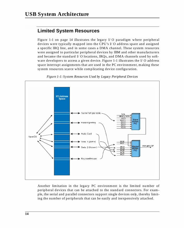
USB System Architecture
Limited System Resources
Figure 1-1 on page 14 illustrates the legacy I/O paradigm where peripheraldevices were typically mapped into the CPU’s I/O address space and assigneda specific IRQ line, and in some cases a DMA channel. These system resourceswere assigned to particular peripheral devices by IBM and other manufacturersand became the standard I/O locations, IRQs, and DMA channels used by soft-ware developers to access a given device. Figure 1-1 illustrates the I/O addressspace interrupt assignments that are used in the PC environment, making thesesystem resources scarce while complicating device configuration.
Another limitation in the legacy PC environment is the limited number ofperipheral devices that can be attached to the standard connectors. For exam-ple, the serial and parallel connectors support single devices only, thereby limit-ing the number of peripherals that can be easily and inexpensively attached.
Figure 1-1: System Resources Used by Legacy Peripheral Devices
14
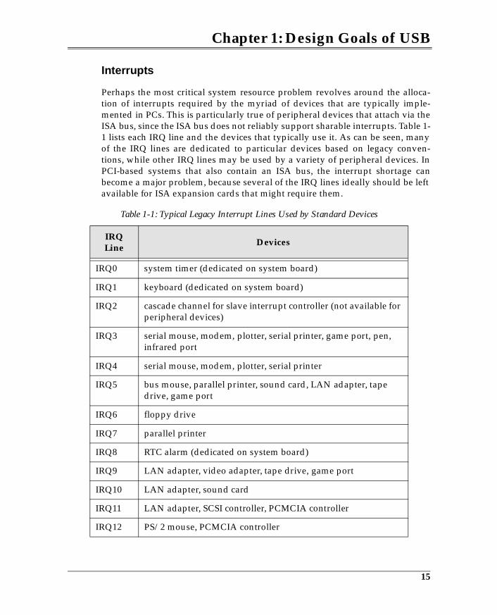
Chapter 1: Design Goals of USB
Interrupts
Perhaps the most critical system resource problem revolves around the alloca-tion of interrupts required by the myriad of devices that are typically imple-mented in PCs. This is particularly true of peripheral devices that attach via theISA bus, since the ISA bus does not reliably support sharable interrupts. Table 1-1 lists each IRQ line and the devices that typically use it. As can be seen, manyof the IRQ lines are dedicated to particular devices based on legacy conven-tions, while other IRQ lines may be used by a variety of peripheral devices. InPCI-based systems that also contain an ISA bus, the interrupt shortage canbecome a major problem, because several of the IRQ lines ideally should be leftavailable for ISA expansion cards that might require them.
Table 1-1: Typical Legacy Interrupt Lines Used by Standard Devices
IRQ Line
Devices
IRQ0 system timer (dedicated on system board)
IRQ1 keyboard (dedicated on system board)
IRQ2 cascade channel for slave interrupt controller (not available for peripheral devices)
IRQ3 serial mouse, modem, plotter, serial printer, game port, pen, infrared port
IRQ4 serial mouse, modem, plotter, serial printer
IRQ5 bus mouse, parallel printer, sound card, LAN adapter, tape drive, game port
IRQ6 floppy drive
IRQ7 parallel printer
IRQ8 RTC alarm (dedicated on system board)
IRQ9 LAN adapter, video adapter, tape drive, game port
IRQ10 LAN adapter, sound card
IRQ11 LAN adapter, SCSI controller, PCMCIA controller
IRQ12 PS/2 mouse, PCMCIA controller
15
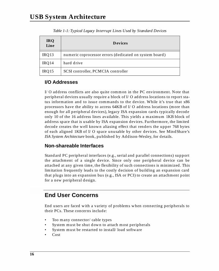
USB System Architecture
I/O Addresses
I/O address conflicts are also quite common in the PC environment. Note thatperipheral devices usually require a block of I/O address locations to report sta-tus information and to issue commands to the device. While it’s true that x86processors have the ability to access 64KB of I/O address locations (more thanenough for all peripheral devices), legacy ISA expansion cards typically decodeonly 10 of the 16 address lines available. This yields a maximum 1KB block ofaddress space that is usable by ISA expansion devices. Furthermore, the limiteddecode creates the well known aliasing effect that renders the upper 768 bytesof each aligned 1KB of I/O space unusable by other devices. See MindShare’sISA System Architecture book, published by Addison-Wesley, for details.
Non-shareable Interfaces
Standard PC peripheral interfaces (e.g., serial and parallel connections) supportthe attachment of a single device. Since only one peripheral device can beattached at any given time, the flexibility of such connections is minimized. Thislimitation frequently leads to the costly decision of building an expansion cardthat plugs into an expansion bus (e.g., ISA or PCI) to create an attachment pointfor a new peripheral design.
End User Concerns
End users are faced with a variety of problems when connecting peripherals totheir PCs. These concerns include:
• Too many connector/cable types• System must be shut down to attach most peripherals• System must be restarted to install/load software• Cost
IRQ13 numeric coprocessor errors (dedicated on system board)
IRQ14 hard drive
IRQ15 SCSI controller, PCMCIA controller
Table 1-1: Typical Legacy Interrupt Lines Used by Standard Devices
IRQ Line
Devices
16
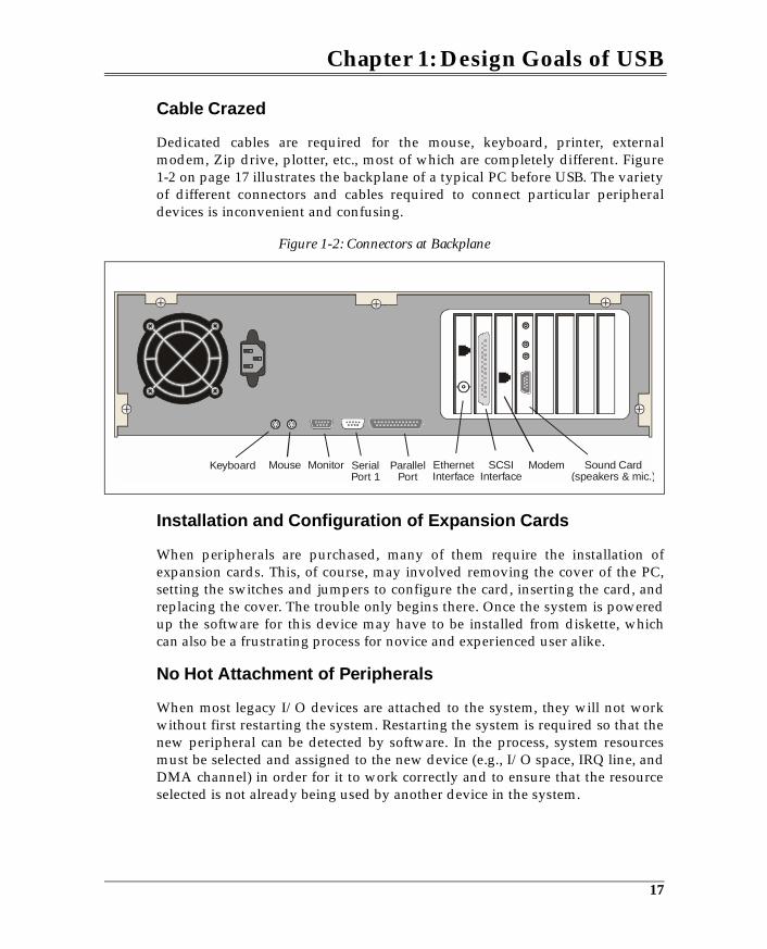
Chapter 1: Design Goals of USB
Cable Crazed
Dedicated cables are required for the mouse, keyboard, printer, externalmodem, Zip drive, plotter, etc., most of which are completely different. Figure1-2 on page 17 illustrates the backplane of a typical PC before USB. The varietyof different connectors and cables required to connect particular peripheraldevices is inconvenient and confusing.
Installation and Configuration of Expansion Cards
When peripherals are purchased, many of them require the installation ofexpansion cards. This, of course, may involved removing the cover of the PC,setting the switches and jumpers to configure the card, inserting the card, andreplacing the cover. The trouble only begins there. Once the system is poweredup the software for this device may have to be installed from diskette, whichcan also be a frustrating process for novice and experienced user alike.
No Hot Attachment of Peripherals
When most legacy I/O devices are attached to the system, they will not workwithout first restarting the system. Restarting the system is required so that thenew peripheral can be detected by software. In the process, system resourcesmust be selected and assigned to the new device (e.g., I/O space, IRQ line, andDMA channel) in order for it to work correctly and to ensure that the resourceselected is not already being used by another device in the system.
Figure 1-2: Connectors at Backplane
Keyboard Mouse Monitor SerialPort 1
Modem Sound Card(speakers & mic.)
ParallelPort
EthernetInterface
SCSIInterface
17
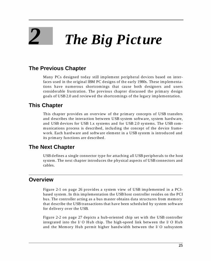
2 The Big Picture
The Previous ChapterMany PCs designed today still implement peripheral devices based on inter-faces used in the original IBM PC designs of the early 1980s. These implementa-tions have numerous shortcomings that cause both designers and usersconsiderable frustration. The previous chapter discussed the primary designgoals of USB 2.0 and reviewed the shortcomings of the legacy implementation.
This ChapterThis chapter provides an overview of the primary concepts of USB transfersand describes the interaction between USB system software, system hardware,and USB devices for USB 1.x systems and for USB 2.0 systems. The USB com-munications process is described, including the concept of the device frame-work. Each hardware and software element in a USB system is introduced andits primary functions are described.
The Next ChapterUSB defines a single connector type for attaching all USB peripherals to the hostsystem. The next chapter introduces the physical aspects of USB connectors andcables.
Overview
Figure 2-1 on page 26 provides a system view of USB implemented in a PCI-based system. In this implementation the USB host controller resides on the PCIbus. The controller acting as a bus master obtains data structures from memorythat describe the USB transactions that have been scheduled by system softwarefor delivery over the USB.
Figure 2-2 on page 27 depicts a hub-oriented chip set with the USB controllerintegrated into the I/O Hub chip. The high-speed link between the I/O Huband the Memory Hub permit higher bandwidth between the I/O subsystem
25
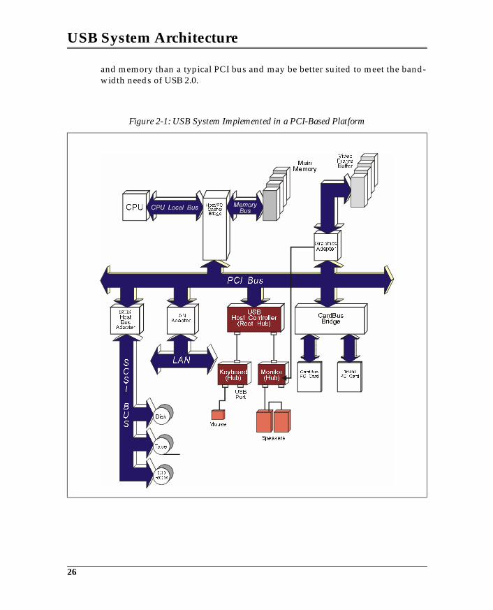
USB System Architecture
and memory than a typical PCI bus and may be better suited to meet the band-width needs of USB 2.0.
Figure 2-1: USB System Implemented in a PCI-Based Platform
!"
USBHost Controller(Root Hub)
CardBusBridge
Keyboard(Hub)
Monitor(Hub)
MainMemory
26
Chapter 2: The Big Picture
Figure 2-2: USB Controller Integrated into I/O Hub Chip
!"#$%
&'
%( ')#
#%*
+'
,
-./ !0
!
1#"
%%"
%%"
)'
'2
'
3
45.)
67
8
67
27
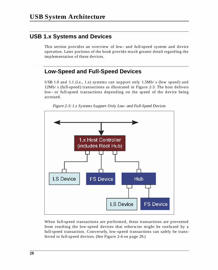
USB System Architecture
USB 1.x Systems and Devices
This section provides an overview of low- and full-speed system and deviceoperation. Later portions of the book provide much greater detail regarding theimplementation of these devices.
Low-Speed and Full-Speed Devices
USB 1.0 and 1.1 (i.e., 1.x) systems can support only 1.5Mb/s (low speed) and12Mb/s (full-speed) transactions as illustrated in Figure 2-3. The host deliverslow- or full-speed transactions depending on the speed of the device beingaccessed.
When full-speed transactions are performed, these transactions are preventedfrom reaching the low-speed devices that otherwise might be confused by afull-speed transaction. Conversely, low-speed transactions can safely be trans-ferred to full-speed devices. (See Figure 2-4 on page 29.)
Figure 2-3: 1.x Systems Support Only Low- and Full-Speed Devices
28
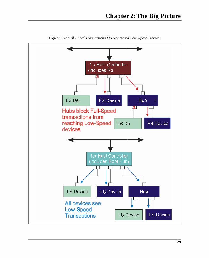
Chapter 2: The Big Picture
Figure 2-4: Full-Speed Transactions Do Not Reach Low-Speed Devices
29
3 Cables and Connectors
The Previous ChapterThe previous chapter provided an overview of the primary concepts of USBtransfers and described the interaction between USB system software, systemhardware, and USB devices for USB 1.x systems and for USB 2.0 system. TheUSB communications process is described, including the concept of the deviceframework. Each hardware and software element in a USB system is introducedand its primary functions are described.
This ChapterUSB defines a single connector type for attaching all USB peripherals to the hostsystem. This chapter introduces the primary mechanical elements of USB con-nectors and cables.
The Next ChapterThe next chapter discusses USB power distribution, along with issues related tobus-powered devices and the operation of self-powered devices. The chapteralso discusses the role of host software in detecting and reporting power-relatedproblems.
The Connectors
USB connectors are designed to permit any USB peripheral device to beattached to a hub port. Hub ports will be located at the back of the computer ormay be associated with other peripheral devices such as monitors and printers,or are available on stand-alone hub devices.
Many USB peripherals have the USB cable permanently attached, while othershave detachable USB cables. If the same connector were used on both ends of a
69
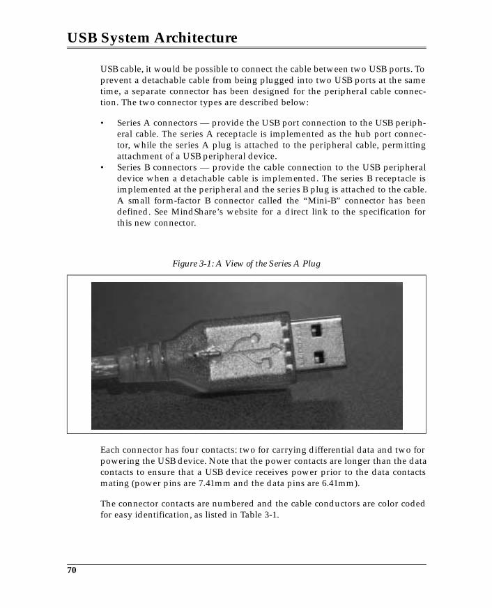
USB System Architecture
USB cable, it would be possible to connect the cable between two USB ports. Toprevent a detachable cable from being plugged into two USB ports at the sametime, a separate connector has been designed for the peripheral cable connec-tion. The two connector types are described below:
• Series A connectors — provide the USB port connection to the USB periph-eral cable. The series A receptacle is implemented as the hub port connec-tor, while the series A plug is attached to the peripheral cable, permittingattachment of a USB peripheral device.
• Series B connectors — provide the cable connection to the USB peripheraldevice when a detachable cable is implemented. The series B receptacle isimplemented at the peripheral and the series B plug is attached to the cable.A small form-factor B connector called the “Mini-B” connector has beendefined. See MindShare’s website for a direct link to the specification forthis new connector.
Each connector has four contacts: two for carrying differential data and two forpowering the USB device. Note that the power contacts are longer than the datacontacts to ensure that a USB device receives power prior to the data contactsmating (power pins are 7.41mm and the data pins are 6.41mm).
The connector contacts are numbered and the cable conductors are color codedfor easy identification, as listed in Table 3-1.
Figure 3-1: A View of the Series A Plug
70
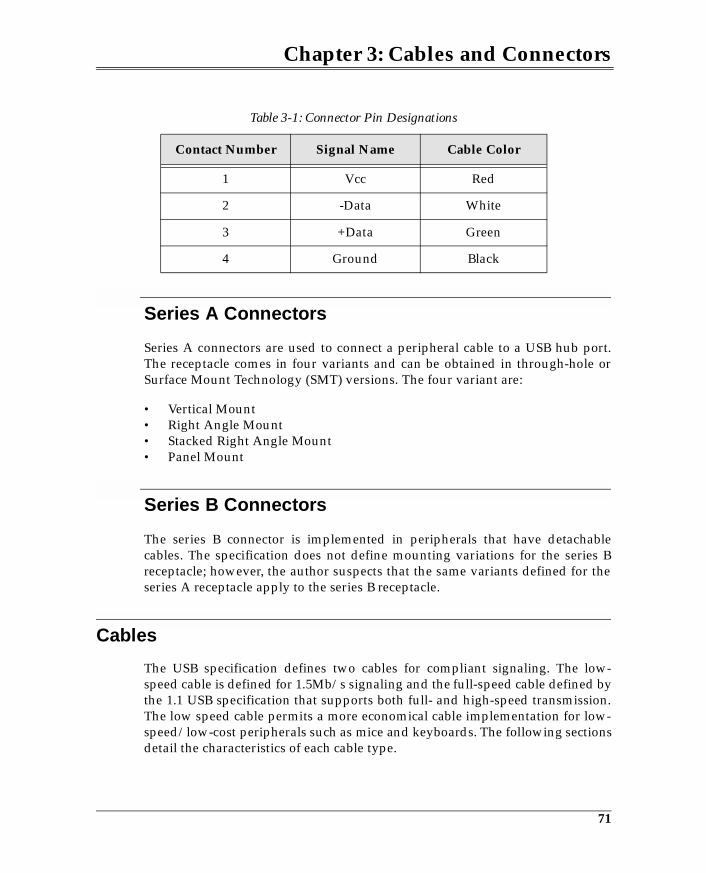
Chapter 3: Cables and Connectors
Series A Connectors
Series A connectors are used to connect a peripheral cable to a USB hub port.The receptacle comes in four variants and can be obtained in through-hole orSurface Mount Technology (SMT) versions. The four variant are:
• Vertical Mount• Right Angle Mount• Stacked Right Angle Mount• Panel Mount
Series B Connectors
The series B connector is implemented in peripherals that have detachablecables. The specification does not define mounting variations for the series Breceptacle; however, the author suspects that the same variants defined for theseries A receptacle apply to the series B receptacle.
Cables
The USB specification defines two cables for compliant signaling. The low-speed cable is defined for 1.5Mb/s signaling and the full-speed cable defined bythe 1.1 USB specification that supports both full- and high-speed transmission.The low speed cable permits a more economical cable implementation for low-speed/low-cost peripherals such as mice and keyboards. The following sectionsdetail the characteristics of each cable type.
Table 3-1: Connector Pin Designations
Contact Number Signal Name Cable Color
1 Vcc Red
2 -Data White
3 +Data Green
4 Ground Black
71
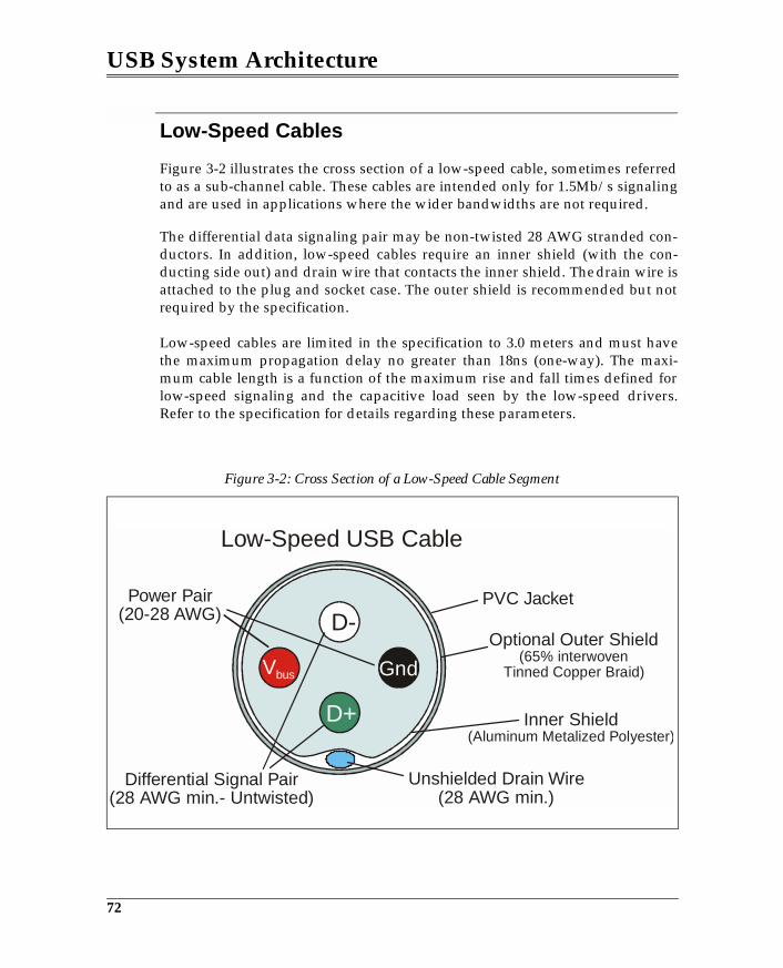
USB System Architecture
Low-Speed Cables
Figure 3-2 illustrates the cross section of a low-speed cable, sometimes referredto as a sub-channel cable. These cables are intended only for 1.5Mb/s signalingand are used in applications where the wider bandwidths are not required.
The differential data signaling pair may be non-twisted 28 AWG stranded con-ductors. In addition, low-speed cables require an inner shield (with the con-ducting side out) and drain wire that contacts the inner shield. The drain wire isattached to the plug and socket case. The outer shield is recommended but notrequired by the specification.
Low-speed cables are limited in the specification to 3.0 meters and must havethe maximum propagation delay no greater than 18ns (one-way). The maxi-mum cable length is a function of the maximum rise and fall times defined forlow-speed signaling and the capacitive load seen by the low-speed drivers.Refer to the specification for details regarding these parameters.
Figure 3-2: Cross Section of a Low-Speed Cable Segment
Power Pair(20-28 AWG)
Differential Signal Pair(28 AWG min.- Untwisted)
Low-Speed USB Cable
D-
D+
GndVbus
Inner Shield (Aluminum Metalized Polyester)
Optional Outer Shield (65% interwoven
Tinned Copper Braid)
PVC Jacket
Unshielded Drain Wire(28 AWG min.)
72
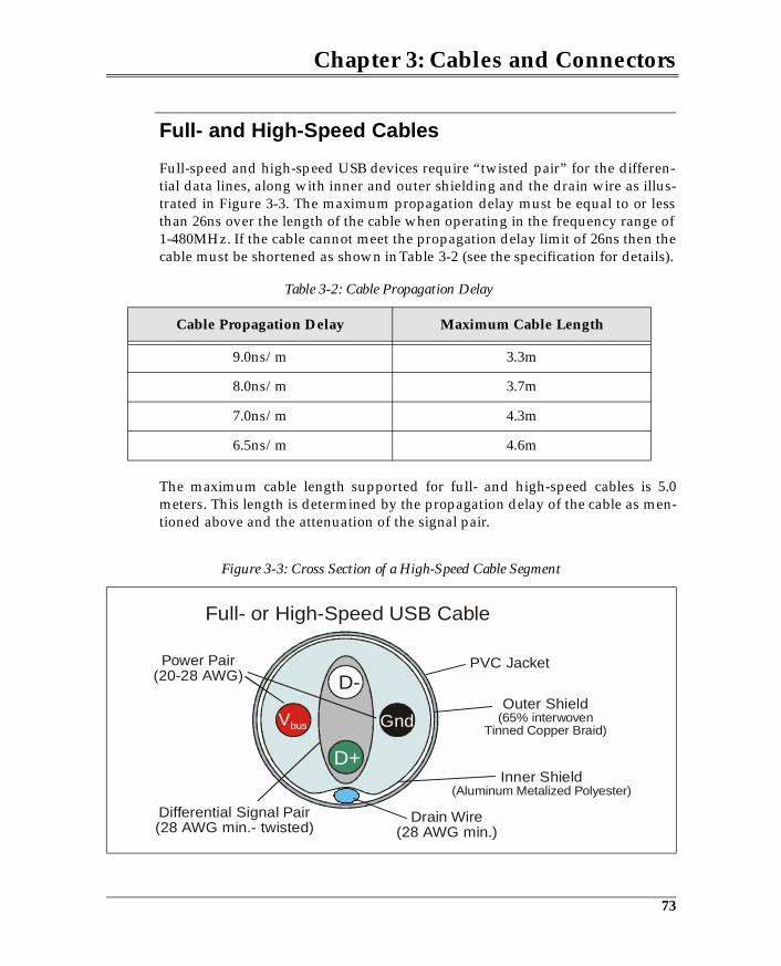
Chapter 3: Cables and Connectors
Full- and High-Speed Cables
Full-speed and high-speed USB devices require “twisted pair” for the differen-tial data lines, along with inner and outer shielding and the drain wire as illus-trated in Figure 3-3. The maximum propagation delay must be equal to or lessthan 26ns over the length of the cable when operating in the frequency range of1-480MHz. If the cable cannot meet the propagation delay limit of 26ns then thecable must be shortened as shown in Table 3-2 (see the specification for details).
The maximum cable length supported for full- and high-speed cables is 5.0meters. This length is determined by the propagation delay of the cable as men-tioned above and the attenuation of the signal pair.
Table 3-2: Cable Propagation Delay
Cable Propagation Delay Maximum Cable Length
9.0ns/m 3.3m
8.0ns/m 3.7m
7.0ns/m 4.3m
6.5ns/m 4.6m
Figure 3-3: Cross Section of a High-Speed Cable Segment
Power Pair(20-28 AWG)
Differential Signal Pair(28 AWG min.- twisted)
Full- or High-Speed USB Cable
D-
D+
GndVbus
Inner Shield (Aluminum Metalized Polyester)
Outer Shield (65% interwoven
Tinned Copper Braid)
PVC Jacket
Drain Wire(28 AWG min.)
73
4 USB Cable Power Distribution
The Previous ChapterUSB defines a single connector type for attaching all USB peripherals to the hostsystem. The previous chapter introduced some of the physical and electricalproperties of USB connectors and cables.
This ChapterThis chapter discusses USB power distribution, along with issues related to bus-powered devices and the operation of self-powered devices. The chapter alsodiscusses the role of host software in detecting and reporting power-relatedproblems.
The Next ChapterUSB employs NRZI encoding and differential signaling to transfer informationacross USB cables. The next chapter discusses the low- and full-speed signalingenvironment, including the differential signaling and NRZI encoding tech-niques used by the USB. The signaling environment must also support a widerange of other signal-related functions such as: detecting device attachment andremoval, suspending and resuming operation, resetting a device, and others, allof which are discussed in this chapter. Note that high-speed devices are dis-cussed later in this book.
USB Power
All USB ports supply power for devices that are attached. Peripheral devicesand hubs can be attached to a given port and use the available cable power orcan implement their own power supply. This chapter details both cable- andself-powered hubs and devices.
75
USB System Architecture
Hubs
A major function associated with a hub is the distribution and control of cablepower. Hubs may derive all power from the upstream cable or may includetheir own power supply for powering downstream ports. Hubs must also pro-vide voltage regulation and ensure current is limited to downstream ports forsafety considerations.
Hubs, like all USB devices, must include descriptors to specify their capabilities.A major portion of a hub’s descriptor definition relates to power-related issues.
Current Budget
A fully rated port must be able to provide five units of current (500ma) to theattached device. Self-powered hubs (including the root hub) having their ownlocal power supply can provide the maximum rated power to each port. How-ever, bus-powered hubs have only the bus power that they receive from theupstream cable to distribute to all of their USB ports. This can severely limit theamount of current that is available for USB devices that attach to bus-poweredhub ports. The minimum current available at a port is 100ma.
Hubs specify whether they are self-powered as part of their configurationdescriptor as shown in Table 4-1. The shaded area shows a bit-mapped“Attribute” field that defines the hub’s power implementation. Note that bit 7 isnow reserved and must be set to 1. This setting in the 1.x environment indicatedwhether the device was bus powered.
If a device loses its external power source, it must not consume additionalpower from the bus to make up the deficit such that the bus power consumedexceeds the amount reported in the “MaxPower” field of the configurationdescriptor. If the device cannot continue to operate with local power removed, itwill no longer respond to accesses and software will be notified of the failure.USB system software may be able to detect that local power has been removedby checking device status.
76
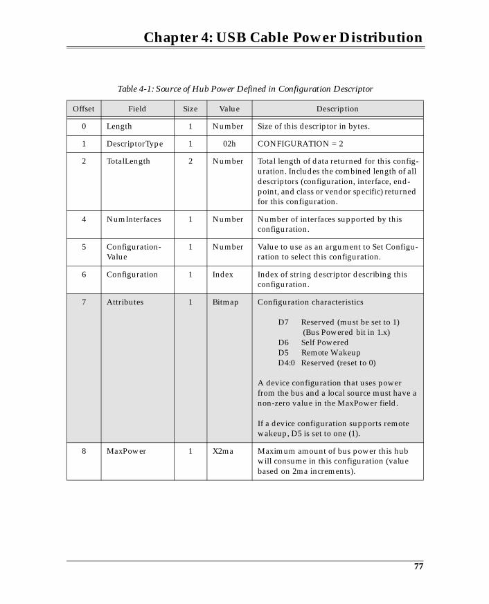
Chapter 4: USB Cable Power Distribution
Table 4-1: Source of Hub Power Defined in Configuration Descriptor
Offset Field Size Value Description
0 Length 1 Number Size of this descriptor in bytes.
1 DescriptorType 1 02h CONFIGURATION = 2
2 TotalLength 2 Number Total length of data returned for this config-uration. Includes the combined length of all descriptors (configuration, interface, end-point, and class or vendor specific) returned for this configuration.
4 NumInterfaces 1 Number Number of interfaces supported by this configuration.
5 Configuration-Value
1 Number Value to use as an argument to Set Configu-ration to select this configuration.
6 Configuration 1 Index Index of string descriptor describing this configuration.
7 Attributes 1 Bitmap Configuration characteristics
D7 Reserved (must be set to 1) (Bus Powered bit in 1.x) D6 Self Powered D5 Remote Wakeup D4:0 Reserved (reset to 0)
A device configuration that uses power from the bus and a local source must have a non-zero value in the MaxPower field.
If a device configuration supports remote wakeup, D5 is set to one (1).
8 MaxPower 1 X2ma Maximum amount of bus power this hub will consume in this configuration (value based on 2ma increments).
77
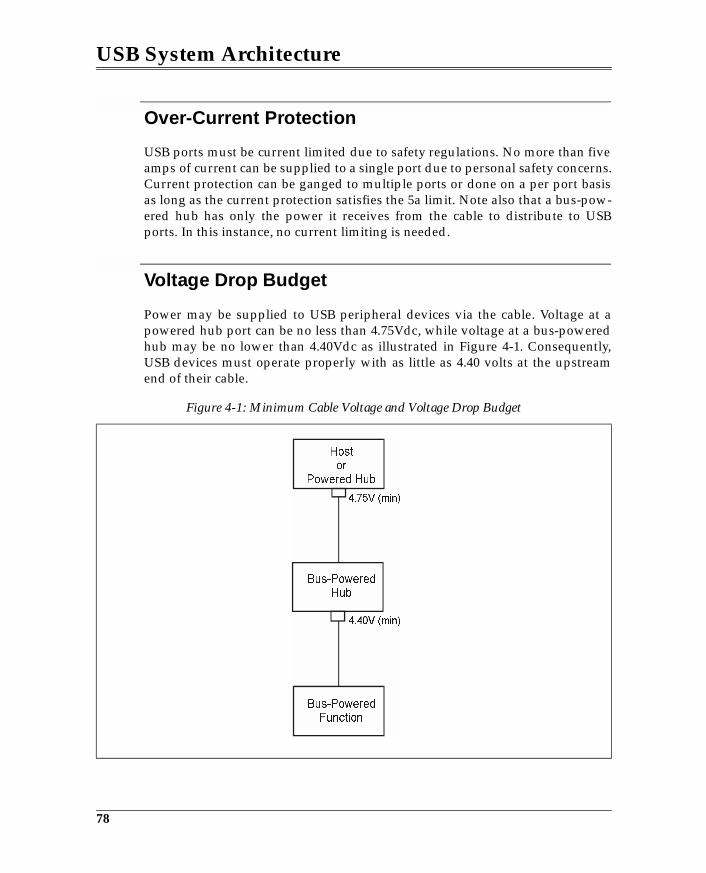
USB System Architecture
Over-Current Protection
USB ports must be current limited due to safety regulations. No more than fiveamps of current can be supplied to a single port due to personal safety concerns.Current protection can be ganged to multiple ports or done on a per port basisas long as the current protection satisfies the 5a limit. Note also that a bus-pow-ered hub has only the power it receives from the cable to distribute to USBports. In this instance, no current limiting is needed.
Voltage Drop Budget
Power may be supplied to USB peripheral devices via the cable. Voltage at apowered hub port can be no less than 4.75Vdc, while voltage at a bus-poweredhub may be no lower than 4.40Vdc as illustrated in Figure 4-1. Consequently,USB devices must operate properly with as little as 4.40 volts at the upstreamend of their cable.
Figure 4-1: Minimum Cable Voltage and Voltage Drop Budget
78

Chapter 4: USB Cable Power Distribution
Power Switching
Hubs apply power to ports in one of the following ways:
• Direct power — not switched• Ganged switching to all ports in common• Individual port power switching
The power switching supported by a given hub is specified within the hub’sendpoint zero descriptor. Table 4-2 on page 79 shows a portion of the hub’s end-point descriptor. Note that data bits D0 and D1 at offset 3 define the powerswitching mode supported by the hub.
Table 4-2: Power Switching Mode Supported Is Defined by the Hub Class Descriptor
Offset Field Size Description
0 DescLength 1 Number of bytes in the descriptor, including this byte.
1 Descriptor-Type
1 Descriptor Type
2 NbrPorts 1 Number of downstream ports that this hub sup-ports.
3 HubCharac-teristics
2 D1:D0 Power Switching Mode
00 Ganged power switching (all ports pow-ered at once)
01 Individual port power switching 1X No power switching (ports always pow-
ered on when hub is on, and off when hub is off).
D15:D2 Defines other hub characteristics
79
5 LS/FS Signaling Environment
The Previous ChapterThe previous chapter discussed USB power distribution, along with issuesrelated to bus powered devices and the operation of self-powered devices. Thechapter also discussed the role of host software in detecting and reportingpower-related problems.
This ChapterUSB employs NRZI encoding and differential signaling to transfer informationacross USB cables. This chapter discusses the low- and full-speed signalingenvironment, including the differential signaling and NRZI encoding tech-niques used by the USB. The signaling environment must also support a widerange of other signal-related functions such as: detecting device attachment andremoval, suspending and resuming operation, resetting a device, and others, allof which are discussed in this chapter.
The Next Chapter
USB supports four transfer types: interrupt, bulk, isochronous, and control.These transfer types and the process used to initiate and perform them aredescribed in the next chapter.
Overview
The LS/FS signaling interface provides the means to support a wide variety ofevents including:
• Detection of LS device attachment• Detection of FS device attachment• Resetting the device
93
USB System Architecture
• Start of Packet (SOP) recognition• End of Packet (EOP) recognition• Differential data signaling• Data encoding and recovery
The signaling interfaces for full-speed and low-speed devices are similar buthave a few important differences that will be discussed in the following sec-tions. Figure 5-1 illustrates the signaling interface for a hub and an attached FSdevice. The primary elements of the signaling interface include:
• Differential drivers• Differential receivers• Single-ended receivers• Pull-down resistors on data lines at hub (15KΩ)• Pull-up resistor on D+ at full-speed device (1.5KΩ)
Detecting Device Attachment and Speed Detect
Before transferring information to or from a given USB device, host softwaremust first detect its presence. USB is designed to detect the attachment ofdevices to the USB, after which transactions may be initiated by host software toconfigure the device for normal operation.
USB hubs monitor each port to observe a connect or disconnect event. Deviceattachment can only be detected when power has been applied to the port. Fig-ure 5-2 illustrates a USB port interface when no device is attached. The pull-down resistors on the D+ and D- lines ensure that both data lines are nearground. When no device is attached, the single-ended receivers detect an elec-trical low on both data lines. USB devices must include a pull-up resistor oneither D+ or D- (depending on its speed) to enable connect detection.
94
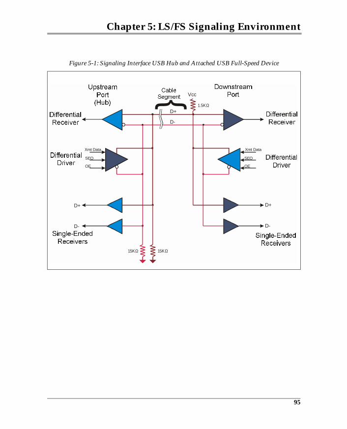
Chapter 5: LS/FS Signaling Environment
Figure 5-1: Signaling Interface USB Hub and Attached USB Full-Speed Device
Vcc
D+
D+D+
Xmt Data Xmt Data
D-
OE OE
D-D-
SEO
15ΚΩ
1.5ΚΩ
SEO
15ΚΩ
95
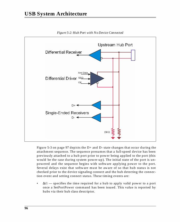
USB System Architecture
Figure 5-3 on page 97 depicts the D+ and D- state changes that occur during theattachment sequence. The sequence presumes that a full-speed device has beenpreviously attached to a hub port prior to power being applied to the port (thiswould be the case during system power-up). The initial state of the port is un-powered and the sequence begins with software applying power to the port.Several delays exist that software must be aware of so that hub status is notchecked prior to the device signaling connect and the hub detecting the connec-tion event and setting connect status. These timing events are:
• ∆t1 — specifies the time required for a hub to apply valid power to a portonce a SetPortPower command has been issued. This value is reported byhubs via their hub class descriptor.
Figure 5-2: Hub Port with No Device Connected
D+
Xmt Data
OE
D-
SEO
15ΚΩ
96
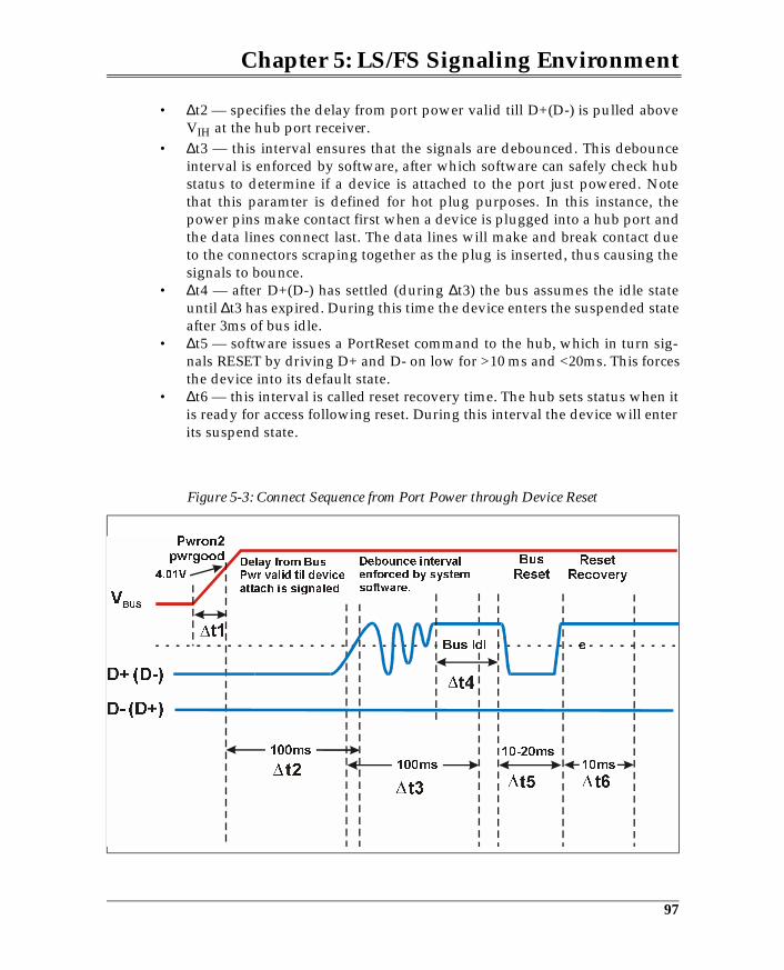
Chapter 5: LS/FS Signaling Environment
• ∆t2 — specifies the delay from port power valid till D+(D-) is pulled aboveVIH at the hub port receiver.
• ∆t3 — this interval ensures that the signals are debounced. This debounceinterval is enforced by software, after which software can safely check hubstatus to determine if a device is attached to the port just powered. Notethat this paramter is defined for hot plug purposes. In this instance, thepower pins make contact first when a device is plugged into a hub port andthe data lines connect last. The data lines will make and break contact dueto the connectors scraping together as the plug is inserted, thus causing thesignals to bounce.
• ∆t4 — after D+(D-) has settled (during ∆t3) the bus assumes the idle stateuntil ∆t3 has expired. During this time the device enters the suspended stateafter 3ms of bus idle.
• ∆t5 — software issues a PortReset command to the hub, which in turn sig-nals RESET by driving D+ and D- on low for >10 ms and <20ms. This forcesthe device into its default state.
• ∆t6 — this interval is called reset recovery time. The hub sets status when itis ready for access following reset. During this interval the device will enterits suspend state.
Figure 5-3: Connect Sequence from Port Power through Device Reset
Bus Idl e
BusReset
ResetRecovery
10-20ms
t3
97
6 LS/FS Transfer Types & Scheduling
The Previous ChapterUSB employs NRZI encoding and differential signaling to transfer informationacross USB cables. The previous chapter discussed the low- and full-speed sig-naling environment, including the differential signaling and NRZI encodingtechniques used by the USB. The signaling environment must also support awide range of other signal-related functions such as: detecting device attach-ment and removal, suspending and resuming operation, resetting a device, andothers, all of which were discussed in the previous chapter.
This ChapterUSB supports four transfer types: interrupt, bulk, isochronous, and control.These transfer types and the process used to initiate and perform them aredescribed in this chapter.
The Next ChapterEvery transfer broadcast over the USB consists of a combination of packets.These packets are combined to define individual transactions that are per-formed as part of a larger transfer. Each transaction type is defined, along withthe individual packets that compose it.
Overview
Each endpoint within a given USB device has particular characteristics that dic-tate how it must be accessed. The transfer characteristics relate to the require-ments of the application. The following four transfer types have been definedby the USB specification, each of which reflects the nature of transfers that maybe required by a USB device endpoint:
117
USB System Architecture
• Interrupt transfer — an interrupt transfer is used for devices that are typi-cally thought of as interrupt-driven devices in legacy PC implementations.USB devices that are interrupt driven must be polled periodically to see ifthe device has data to transfer. For example, in legacy PC systems a hard-ware interrupt is generated each time a key is pressed on the keyboard tonotify the processor that it must execute a software interrupt routine to ser-vice the keyboard, whereas a USB keyboard is polled periodically to deter-mine if keyboard data (e.g., resulting from a key being pressed) is ready tobe transferred. The polling rate, of course, is critical; it must be frequentenough to ensure that data is not lost but not so frequent that bus band-width is needlessly reduced.
• Bulk transfer — a bulk transfer is used for transferring large blocks of datathat have no periodic or transfer rate requirement. An example of a bulktransfer is a print job being transferred to a USB printer. While transferspeed is important for performance, a print job delivered slowly does notresult in lost or corrupted data.
• Isochronous transfer — an isochronous transfer requires a constant deliveryrate. Devices that use isochronous transfers must ensure that rate matchingbetween the sender and receiver can be accomplished. For example, a USBmicrophone and speaker would use isochronous transfers to ensure that nofrequency distortion results from transferring data across the USB.
• Control transfers — control transfers are used to transfer specific requeststo USB devices and are most commonly used during device configuration.A special transfer sequence is used to pass requests (commands) to adevice, sometimes followed by a data transfer, and always ending withcompletion status.
A given device may have a collection of endpoints, each of which may supporta different transfer type. For example, when a file manager program accesses aUSB-based CD-ROM, the data endpoint is defined as a bulk transfer endpoint,whereas accesses performed by a CD audio program would require isochro-nous transfers be performed from a data endpoint.
Client Initiates Transfer
During the configuration process, the USB driver reads the device descriptors todetermine the type of endpoints that a given device requires for its function.The USB driver determines if sufficient bus bandwidth is available to accommo-date all endpoint transfer requirements. If the bandwidth is available, the USBdriver establishes a communications pipe with the bus bandwidth reservationassociated with the pipe. The driver also apprises the appropriate USB devicedriver that the communications pipe exists for its use.
118
Chapter 6: LS/FS Transfer Types & Scheduling
Communications Pipes
Figure 6-1 on page 120 illustrates the concept of the communications pipes thathave been established for the client driver to communicate with its function.The communications pipes remain inactive until the client requests a transfervia one of the pipes. Note also that the USB device driver knows only aboutcommunications pipes and the endpoints that it must communicate with, and isnot aware of the nature of the low-level USB transfer mechanisms.
The USB specification classifies a communications pipe as either a stream or amessage pipe:
• Streaming pipes — The characteristic of a streaming pipe is that USBimposes no particular format relative to the actual data being transferred.Isochronous, Interrupt, and bulk endpoints fall into this category. Datadelivered to or from these endpoints may have specific structures or for-mats, but these would be class or vendor-specific.
• Message pipes — A message pipe has a specific structure defined by USB.Communication with a control endpoint requires a specific structure andsequence, and the data patterns sent to the endpoint define requests or com-mands that are issued to a device. These requests specify that the devicemust take some action.
Note that in Figure 6-1 on page 120 the pipe at the top of the illustration is tar-geting endpoint zero (the default control endpoint) that every device mustimplement. This communications pipe is bidirectional to allow messages to bepassed in both directions. The other transfer pipes are always unidirectional.This means that a device such as a read/write mass storage device must imple-ment two endpoints for bi-directional data transfer: one for reads and one forwrites.
119
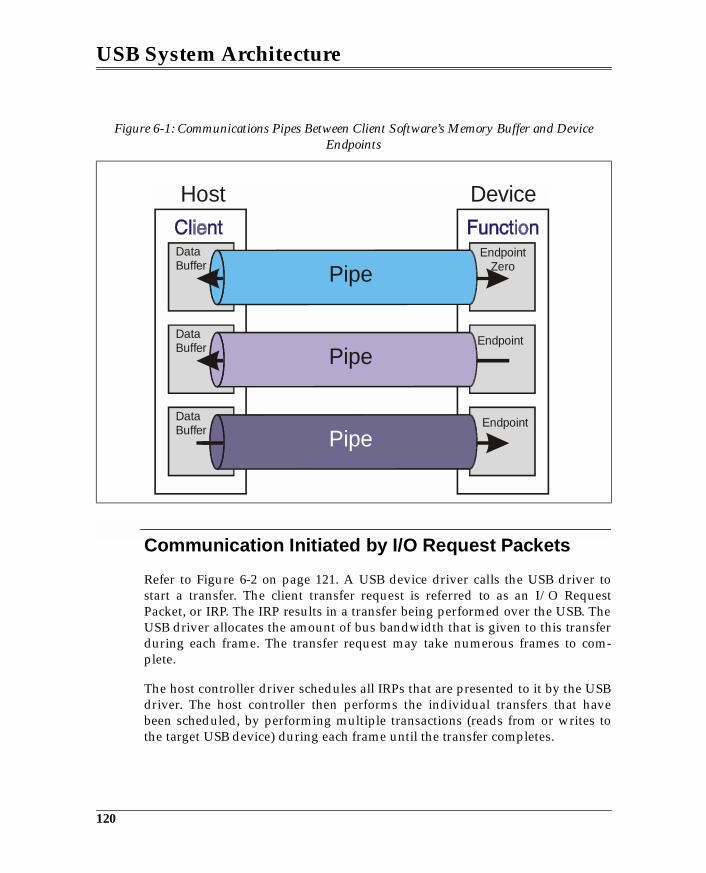
USB System Architecture
Communication Initiated by I/O Request Packets
Refer to Figure 6-2 on page 121. A USB device driver calls the USB driver tostart a transfer. The client transfer request is referred to as an I/O RequestPacket, or IRP. The IRP results in a transfer being performed over the USB. TheUSB driver allocates the amount of bus bandwidth that is given to this transferduring each frame. The transfer request may take numerous frames to com-plete.
The host controller driver schedules all IRPs that are presented to it by the USBdriver. The host controller then performs the individual transfers that havebeen scheduled, by performing multiple transactions (reads from or writes tothe target USB device) during each frame until the transfer completes.
Figure 6-1: Communications Pipes Between Client Software’s Memory Buffer and Device Endpoints
DataBuffer
DataBuffer
DataBuffer
EndpointZero
Endpoint
Endpoint
Pipe
Host Device
Pipe
Pipe
120
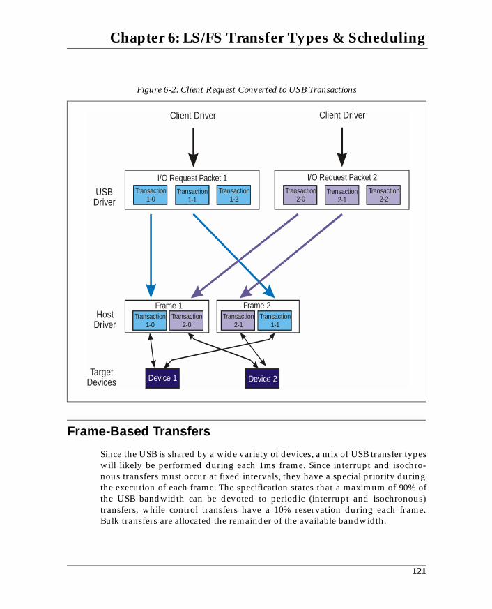
Chapter 6: LS/FS Transfer Types & Scheduling
Frame-Based Transfers
Since the USB is shared by a wide variety of devices, a mix of USB transfer typeswill likely be performed during each 1ms frame. Since interrupt and isochro-nous transfers must occur at fixed intervals, they have a special priority duringthe execution of each frame. The specification states that a maximum of 90% ofthe USB bandwidth can be devoted to periodic (interrupt and isochronous)transfers, while control transfers have a 10% reservation during each frame.Bulk transfers are allocated the remainder of the available bandwidth.
Figure 6-2: Client Request Converted to USB Transactions
Transaction1-0
Transaction1-0
Transaction2-0
Transaction2-1
Transaction1-1
Transaction2-0
Transaction1-2
Transaction2-2
Transaction1-1
Transaction2-1
I/O Request Packet 1
Frame 1 Frame 2
I/O Request Packet 2
Client Driver Client Driver
USBDriver
HostDriver
Target Devices Device 1 Device 2
121
7 Packets & Transactions
The Previous ChapterThe previous chapter introduced and described the four transfer types sup-ported by USB: interrupt, bulk, control, and isochronous. The purpose of thetransfers and their capabilities and limitations were also discussed.
This ChapterEvery transfer broadcast over the USB consists of a combination of packets.These packets are combined to define individual transactions that are per-formed as part of a larger transfer. Each transaction type is defined, along withthe individual packets that compose it.
The Next ChapterInterrupt, bulk, and control transfers require that the successful delivery of databe verified by USB. CRC and other error checking is performed to verify datadelivery and if errors occur retries of the failed transmission are performed.This chapter discusses the various sources of errors and the error detectionmechanisms used by USB to identify them, and the error recovery that is per-formed to overcome them.
Overview
The previous chapter discussed the various transfer types used to communicatewith endpoints within a device. Transfers are performed across the USB usingone or more transactions consisting of a series of packets. Figure 7-1 on page 142illustrates the relationships between the various layers involved in performing atransfer — from the USB device driver ’s request to perform a transfer (IRP) tothe resulting packets that are transmitted across the USB wire to or from thedevice. This chapter deals with individual transactions that are initiated by the
141
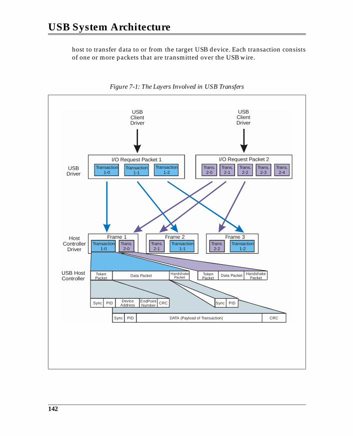
USB System Architecture
host to transfer data to or from the target USB device. Each transaction consistsof one or more packets that are transmitted over the USB wire.
Figure 7-1: The Layers Involved in USB Transfers
Transaction1-0
Transaction1-0
Transaction1-1
Transaction1-2
Trans.2-0
Trans.2-0
Trans.2-1
Trans.2-1
Trans.2-2
Trans.2-2
Trans.2-3
Trans.2-4
Transaction1-2
Transaction1-1
I/O Request Packet 1
Frame 1 Frame 2 Frame 3
I/O Request Packet 2
USB ClientDriver
USB ClientDriver
USBDriver
HostController
Driver
USB HostController
TokenPacket
TokenPacket
Data Packet Data PacketHandshakePacket
HandshakePacket
SyncSync
Sync
PID
PID DATA (Payload of Transaction)
PIDCRC
CRC
DeviceAddress
EndPointNumber
142
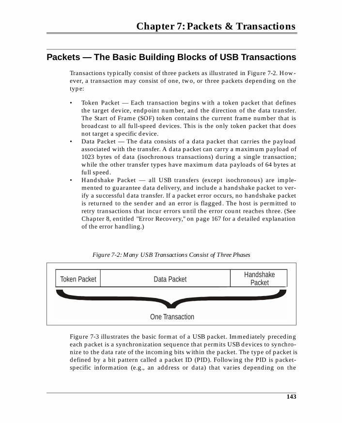
Chapter 7: Packets & Transactions
Packets — The Basic Building Blocks of USB Transactions
Transactions typically consist of three packets as illustrated in Figure 7-2. How-ever, a transaction may consist of one, two, or three packets depending on thetype:
• Token Packet — Each transaction begins with a token packet that definesthe target device, endpoint number, and the direction of the data transfer.The Start of Frame (SOF) token contains the current frame number that isbroadcast to all full-speed devices. This is the only token packet that doesnot target a specific device.
• Data Packet — The data consists of a data packet that carries the payloadassociated with the transfer. A data packet can carry a maximum payload of1023 bytes of data (isochronous transactions) during a single transaction;while the other transfer types have maximum data payloads of 64 bytes atfull speed.
• Handshake Packet — all USB transfers (except isochronous) are imple-mented to guarantee data delivery, and include a handshake packet to ver-ify a successful data transfer. If a packet error occurs, no handshake packetis returned to the sender and an error is flagged. The host is permitted toretry transactions that incur errors until the error count reaches three. (SeeChapter 8, entitled "Error Recovery," on page 167 for a detailed explanationof the error handling.)
Figure 7-3 illustrates the basic format of a USB packet. Immediately precedingeach packet is a synchronization sequence that permits USB devices to synchro-nize to the data rate of the incoming bits within the packet. The type of packet isdefined by a bit pattern called a packet ID (PID). Following the PID is packet-specific information (e.g., an address or data) that varies depending on the
Figure 7-2: Many USB Transactions Consist of Three Phases
Token Packet Data Packet
One Transaction
HandshakePacket
143
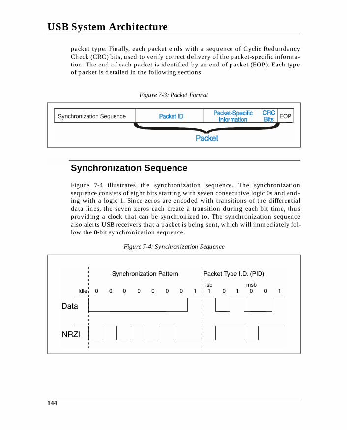
USB System Architecture
packet type. Finally, each packet ends with a sequence of Cyclic RedundancyCheck (CRC) bits, used to verify correct delivery of the packet-specific informa-tion. The end of each packet is identified by an end of packet (EOP). Each typeof packet is detailed in the following sections.
Synchronization Sequence
Figure 7-4 illustrates the synchronization sequence. The synchronizationsequence consists of eight bits starting with seven consecutive logic 0s and end-ing with a logic 1. Since zeros are encoded with transitions of the differentialdata lines, the seven zeros each create a transition during each bit time, thusproviding a clock that can be synchronized to. The synchronization sequencealso alerts USB receivers that a packet is being sent, which will immediately fol-low the 8-bit synchronization sequence.
Figure 7-3: Packet Format
Figure 7-4: Synchronization Sequence
Synchronization Sequence EOP
144
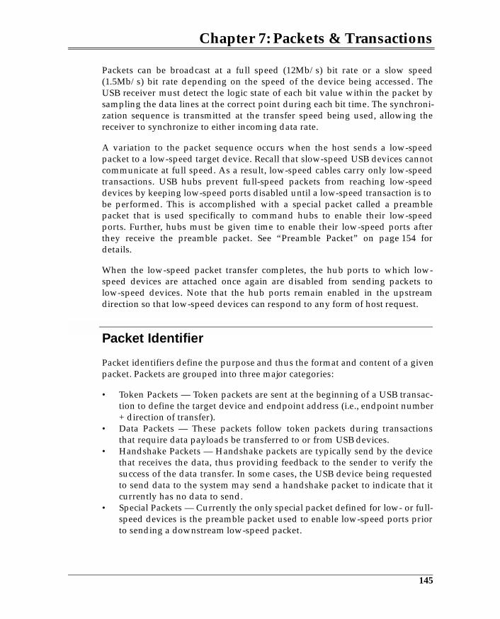
Chapter 7: Packets & Transactions
Packets can be broadcast at a full speed (12Mb/s) bit rate or a slow speed(1.5Mb/s) bit rate depending on the speed of the device being accessed. TheUSB receiver must detect the logic state of each bit value within the packet bysampling the data lines at the correct point during each bit time. The synchroni-zation sequence is transmitted at the transfer speed being used, allowing thereceiver to synchronize to either incoming data rate.
A variation to the packet sequence occurs when the host sends a low-speedpacket to a low-speed target device. Recall that slow-speed USB devices cannotcommunicate at full speed. As a result, low-speed cables carry only low-speedtransactions. USB hubs prevent full-speed packets from reaching low-speeddevices by keeping low-speed ports disabled until a low-speed transaction is tobe performed. This is accomplished with a special packet called a preamblepacket that is used specifically to command hubs to enable their low-speedports. Further, hubs must be given time to enable their low-speed ports afterthey receive the preamble packet. See “Preamble Packet” on page 154 fordetails.
When the low-speed packet transfer completes, the hub ports to which low-speed devices are attached once again are disabled from sending packets tolow-speed devices. Note that the hub ports remain enabled in the upstreamdirection so that low-speed devices can respond to any form of host request.
Packet Identifier
Packet identifiers define the purpose and thus the format and content of a givenpacket. Packets are grouped into three major categories:
• Token Packets — Token packets are sent at the beginning of a USB transac-tion to define the target device and endpoint address (i.e., endpoint number+ direction of transfer).
• Data Packets — These packets follow token packets during transactionsthat require data payloads be transferred to or from USB devices.
• Handshake Packets — Handshake packets are typically send by the devicethat receives the data, thus providing feedback to the sender to verify thesuccess of the data transfer. In some cases, the USB device being requestedto send data to the system may send a handshake packet to indicate that itcurrently has no data to send.
• Special Packets — Currently the only special packet defined for low- or full-speed devices is the preamble packet used to enable low-speed ports priorto sending a downstream low-speed packet.
145
8 Error Recovery
The Previous ChapterEvery transfer broadcast over the USB consists of a combination of packets.These packets are combined to define individual transactions that are per-formed as part of a larger transfer. Each transaction type was defined, alongwith the individual packets that compose it.
This ChapterInterrupt, bulk, and control transfers require that the successful delivery of databe verified by USB. CRC and other error checking is performed to verify datadelivery and if errors occur, retries of the failed transmission are performed.This chapter discusses the various sources of errors and the error detectionmechanisms used by USB to identify them, and the error recovery that is per-formed to overcome them.
The Next ChapterUSB devices support power conservation by entering a suspended state. Thenext chapter discusses the ways that devices are placed into the suspended stateunder software control. It also discusses how software re-awakens devices, andhow a device such as a modem can initiate a wakeup remotely.
Overview
A variety of error conditions are detectable by hardware during the transfer ofdata across the USB. The previous chapter introduced the handshake packetthat has been designed into the USB transaction protocol to verify that a packethas been successfully received. This chapter details all the USB error checkingmechanisms and describes the related error recovery procedures. Error check-ing mechanisms supported by the USB include:
• Packet error checks• False EOP
167
USB System Architecture
• Bus time-out (no response)• Data toggle error checks• Babble — transactions occurring beyond end of frame• LOA — loss of activity on bus
Packet Errors
The USB devices detect three types of packet errors:
• Packet ID (PID) checks• Cyclic Redundancy Checks (CRC)• Bit stuff errors
If any of these error conditions exist, the receiver of the packet must ignore thepacket and not respond to it in any manner. The receiver consequently neversends a packet back to the transmitter if the packet just received contains anerror. Note that the type of packet error detected is not significant to the USBdevices or host as it relates to error recovery. However, the host system maycapture statistics regarding the nature of packet failures. The following sectionsdiscuss each form of packet-related error.
PID Checks
Each packet broadcast over the USB starts with a Packet ID (PID) consisting offour bits and is followed by a PID check field as illustrated in Figure 8-1. Thecheck field is the PID inverted (1’s complement). All potential USB targetdevices must perform the PID check and ignore the packet if an error isdetected, since the definition of the packet is unknown.
168
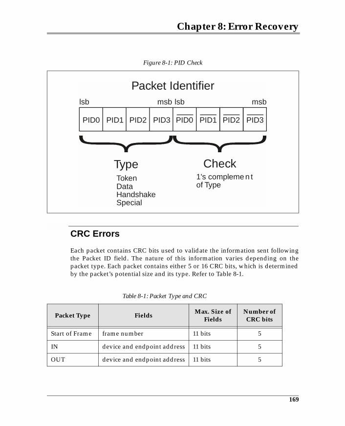
Chapter 8: Error Recovery
CRC Errors
Each packet contains CRC bits used to validate the information sent followingthe Packet ID field. The nature of this information varies depending on thepacket type. Each packet contains either 5 or 16 CRC bits, which is determinedby the packet’s potential size and its type. Refer to Table 8-1.
Figure 8-1: PID Check
Table 8-1: Packet Type and CRC
Packet Type FieldsMax. Size of
FieldsNumber of CRC bits
Start of Frame frame number 11 bits 5
IN device and endpoint address 11 bits 5
OUT device and endpoint address 11 bits 5
Type Check
Packet Identifier
TokenDataHandshakeSpecial
1's compleme n tof Type
lsb lsb msbmsb
PID0PID0 PID1PID1 PID2PID2 PID3PID3
169
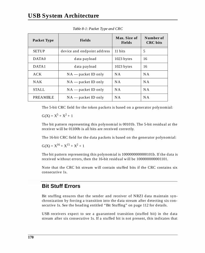
USB System Architecture
The 5-bit CRC field for the token packets is based on a generator polynomial:
G(X) = X5 + X2 + 1
The bit pattern representing this polynomial is 00101b. The 5-bit residual at thereceiver will be 01100b is all bits are received correctly.
The 16-bit CRC field for the data packets is based on the generator polynomial:
G(X) = X16 + X15 + X2 + 1
The bit pattern representing this polynomial is 1000000000000101b. If the data isreceived without errors, then the 16-bit residual will be 1000000000001101.
Note that the CRC bit stream will contain stuffed bits if the CRC contains sixconsecutive 1s.
Bit Stuff Errors
Bit stuffing ensures that the sender and receiver of NRZI data maintain syn-chronization by forcing a transition into the data stream after detecting six con-secutive 1s. See the heading entitled “Bit Stuffing” on page 112 for details.
USB receivers expect to see a guaranteed transition (stuffed bit) in the datastream after six consecutive 1s. If a stuffed bit is not present, this indicates that
SETUP device and endpoint address 11 bits 5
DATA0 data payload 1023 bytes 16
DATA1 data payload 1023 bytes 16
ACK NA — packet ID only NA NA
NAK NA — packet ID only NA NA
STALL NA — packet ID only NA NA
PREAMBLE NA — packet ID only NA NA
Table 8-1: Packet Type and CRC
Packet Type FieldsMax. Size of
FieldsNumber of CRC bits
170
Chapter 8: Error Recovery
the packet has been corrupted or that the sender is not properly generatingstuffed bits, or that the receiver is not decoding the NRZI data correctly.
Packet-Related Error Handling
Any one of the packet-related errors results in the same device behavior. Inevery instance, the receiver of a corrupted packet must ignore the packet andnot respond. The error handling method, however, varies depending on thetransaction and which packet of a given transaction is corrupted.
Token Packet Errors
IN Packet Errors. Consider an IN packet during which some form of packeterror occurs. Since an error is detected in the token packet, it is ignored by thetarget device and no response is returned to the host. The host expects either adata or handshake packet to be returned in response to the IN token. However,since the target does not respond, the host will detect a bus time-out and thetransaction fails. The host is then responsible for retrying the failed transaction.
OUT or SETUP Packet Errors. If an OUT or SETUP packet is beingbroadcast by the host when a packet error is detected, the host will follow thetoken packet with a data packet. The target may decode the data packet withouterror, but may not be able to verify that it is the intended recipient (due to anaddress CRC error), or may not be able to detect the meaning of the data packet(due to a PID check error). Since the target does not respond to the OUT tokennor the following data packet, the host detects a bus time-out and knows andthat the transaction has failed. The host then reschedules the transaction.
Data Packet Errors
During OUT or SETUP Transactions. Errors occurring within datapackets cause the receiving device to discard the data and not respond to thesender. During an OUT transaction, the target, having detected a data packeterror, will not respond with a handshake. The resulting time-out tells the host ofthe failed write. The host then retries the transaction later.
During IN Transactions. During IN transactions, valid data is returned bythe target but the host receives a corrupted data packet. Since the host does notrespond with an ACK handshake, the target is informed that the host did notreceive the data. The host then must retry the transaction.
171

9 USB Power Conservation
The Previous ChapterInterrupt, bulk, and control transfers require that the successful delivery of databe verified by USB. CRC and other error checking is performed to verify datadelivery, and if errors occur, retries of the failed transmission are performed.The previous chapter discussed the various sources of errors and the errordetection mechanisms used by USB to identify them.
This ChapterUSB devices support power conservation by entering a suspend state. Thischapter discusses the ways that devices are placed into the suspend state undersoftware control. It also discusses how software re-awakens devices, and how adevice such as a modem can initiate a wakeup remotely.
The Next ChapterThe next chapter provides a brief introduction to high-speed device operationand sets the stage for a detailed discussion of the high-speed environment.
Power Conservation — Suspend
Suspend is designed to reduce overall power consumption under software con-trol. USB supports two types of suspend:
• Global suspend — all USB devices are placed into the suspend state• Selective suspend — selected devices are placed into the suspend state
When a device enters its suspend state it must consume no more than 500µa ofcurrent. Devices enter suspend after 3ms of no bus activity. Normally devicesare kept from entering the suspend state because they receive a SOF token at thebeginning of every 1ms frame, even if no other USB traffic is occurring.
195
USB System Architecture
Low-speed devices however, see only low-speed traffic, meaning that they donot see the SOF packet nor any full-speed transactions. Consequently, hubsmust signal an idle to K state transition on all low-speed ports at intervals ofless than 3.0ms to prevent low-speed devices from inadvertently entering thesuspend state. To this end the specification minimally requires that the hub sig-nal a low-speed EOP to all low-speed devices at the beginning of each frame.
Device Response to Suspend
When devices enter the suspend state, they must preserve their state and con-sume no more than an average of 500µa of current, or 2.5ma for high-powerdevices that are enable to generate remote wakeup. The specified current drawmust not exceed the specified current limit when averaged over an interval of 1second. A momentary current spike is permitted for configured devices duringthe averaging interval, but must not exceed the device’s power allocation (spec-ified in the max power field of the configuration descriptor). This limit includesthe current draw associated with the pull-up and pull-down resistors on the D-and D+ lines.
Some devices may need to awaken the system in response to an external event.For example, a modem function could be designed to awaken the system whenit receives a “ring indicate” from an external line. It would then be necessary tonotify system software that the modem requires attention.
Hub Response to Suspend
When a hub detects greater than 3ms of inactivity on its upstream port, it mustalso enter the suspend state. Since the hub has detected no bus activity for3.0ms, by definition no activity will have been broadcast to any of the hub’sdownstream ports for 3ms. All downstream ports, along with the hub itself, willdetect the suspend state at approximately the same time.
Upon detecting suspend, hubs take the following actions:
• place their repeaters into the wait for start of packet (WFSOP) state• float all output drivers• maintain static values of all control and status bits• preserve current state info for all downstream ports
All internal clocks are stopped and power consumption from the hub functionis reduced to a minimum.
196
Chapter 9: USB Power Conservation
Since each device attached downstream also enters the suspend state, eachdevice can each draw up to 500µa. This means that the hub itself may drawConfigured bus-powered hubs may also draw up to 2.5ma with devicesattached to it downstream ports. Unconfigured hubs like all other unconfigureddevices must limit current draw to 500µa. Further, when in the suspend state,hubs must be able to supply the maximum current defined for their down-stream ports to support remote wakeup. That is, a device may drive the busduring suspend to wake up the system as will be discussed later in this chapter.
Global Suspend
Global suspend places the entire USB network of devices into the suspend statefrom the top down. This provides for minimum power consumption from theUSB. The host initiates global suspend typically in response to a prolongedperiod of bus inactivity.
Initiating Global Suspend
Global suspend is initiated when all downstream traffic from the root hub is ter-minated. This is done under software control by issuing a global suspendrequest to the root hub’s control endpoint. All USB devices (hubs and functions)automatically enter the suspend state when they encounter 3.0ms of inactivity.
Resume from Global Suspend
Devices awaken from their suspend state when they detect resume signaling onthe bus. Resume is signaled by a non-idle state (K state), initiated in the follow-ing ways:
• by the root hub, causing the resume signaling to occur on all downstreamcable segments.
• by a device on any downstream cable segment attached to an enabled port,causing the hub to reflect the resume signaling back to that port, to all otherenabled ports downstream, and upstream to its root port.
• by device attachment.• by device detachment.• by reset, causing all devices to be reconfigured.
The following sections discuss the methods of handling suspend and resume.
197
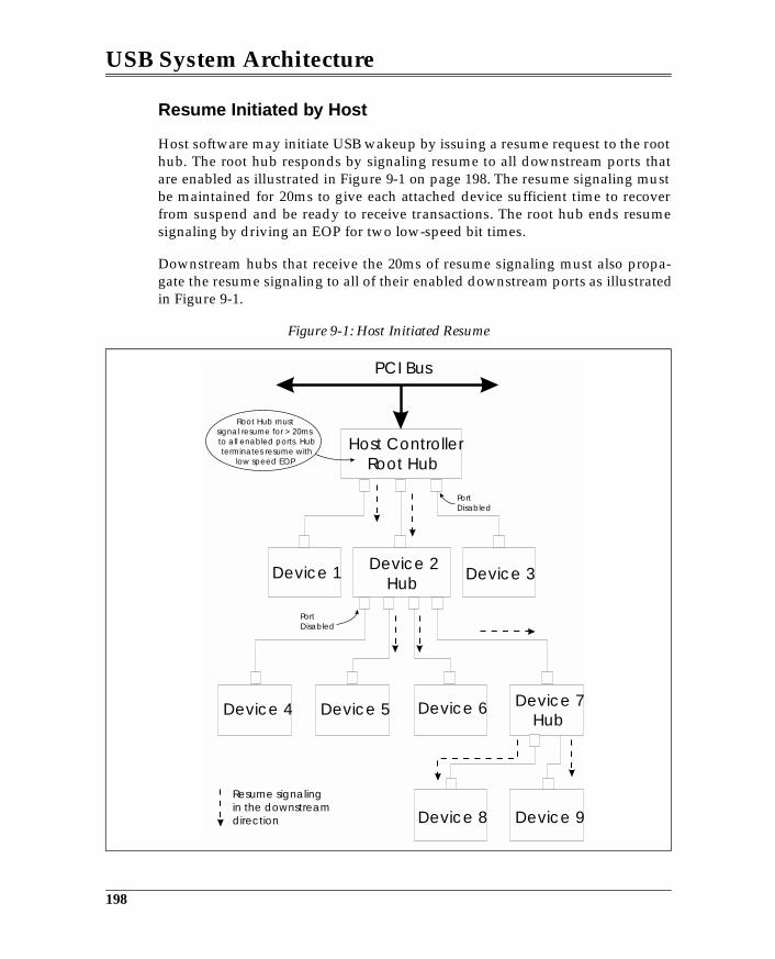
USB System Architecture
Resume Initiated by Host
Host software may initiate USB wakeup by issuing a resume request to the roothub. The root hub responds by signaling resume to all downstream ports thatare enabled as illustrated in Figure 9-1 on page 198. The resume signaling mustbe maintained for 20ms to give each attached device sufficient time to recoverfrom suspend and be ready to receive transactions. The root hub ends resumesignaling by driving an EOP for two low-speed bit times.
Downstream hubs that receive the 20ms of resume signaling must also propa-gate the resume signaling to all of their enabled downstream ports as illustratedin Figure 9-1.
Figure 9-1: Host Initiated Resume
Host ControllerRoot Hub
PCI Bus
Device 2Hub
Device 4 Device 5 Device 6
Device 8 Device 9
Device 7Hub
Device 1 Device 3
PortDisabled
PortDisabled
Resume signalingin the downstreamdirection
Root Hub mustsignal resume for > 20msto all enabled ports. Hubterminates resume with
low speed EOP.
198
Chapter 9: USB Power Conservation
Remote Wakeup from Device
A device in the suspend state may respond to an external event by signaling awakeup to the system via the USB. Resume signaling is initiated by the deviceby driving a K state (non-idle) onto the bus. The actions taken by the hub are:
• signal resume to upstream port• signal resume to all enabled downstream ports• reflect resume signaling back to the originating device
Figure 9-2 illustrates the sequence of events and describes the timing associatedwith device initiated resume. The following steps and timing apply:
1. A K state is signaled by the device to the hub port (t0).2. The port detects the resume signaling.3. Resume signaling is broadcast by hub 7 to its upstream port and to all
enabled downstream ports within 900µs of receiving the resume (t1).4. Hub 2 signals resume to all of its enabled ports within 900µs of receiving
the resume from hub 7.5. Hub 7 ceases driving resume in the upstream direction within 1-15ms of t0.
but not earlier than 100µs and reverses connectivity. This is referred to as t2.6. Hub 2 ceases driving resume in the upstream direction within 10ms of
receiving resume from hub 7, but not earlier than 50µs.7. When the root hub detects the resume signaling, it initiates 20ms of resume
signaling downstream to all ports, including the originating port. 8. The root hub terminates resume signaling by driving two low-speed EOPs.
Note that during the interval between t0 and t2, the host may have started driv-ing resume signaling from the upstream direction, while the downstream hub isstill driving resume signaling. Since it is acceptable to drive both ends of a bussegment to the same state, no problem is encountered.
Remote Wakeup via Hub Port Event
Remote wakeup may be signaled by a hub if it is enabled to produce a remotewakeup. In this case, when a hub detects a status change event (a bit is set ineither the hub port status or status change register), it signals wakeup to the sys-tem in the same fashion as described for remote wakeup. See “Port StatusFields” on page 457 and “Port Change Fields” on page 459 for definition of theevents that can cause a hub to generate remote wakeup.
199
10 Overview of HS Device Operation
The Previous ChapterUSB devices support power conservation by entering a suspend state. The pre-vious chapter introduced the ways that devices are placed into the suspendstate under software control. It also discussed how software re-awakensdevices, and how a device such as a modem can initiate a wakeup remotely.
This ChapterThis chapter provides a brief introduction to high-speed device operation andsets the stage for a detailed discussion of the high-speed environment.
The Next ChapterHigh-speed capable devices must also be able to communicate in the full-speedsignaling environment. High-speed devices add many extensions to the full-speed environment to permit reliable signaling at a 480Mb/s rate. The nextchapter introduces the principles associated with USB high-speed signaling andthe methods used to switch between full- and high-speed operation.
Overview
High-speed device operation is different from low- and full-speed device opera-tion in many ways beyond the obvious difference of transmission rate. Perhapsthe most important difference is that low- and full-speed devices must operateat both high- and full-speed. This ensures that high-speed devices operate insystems that are USB 1.x compliant as well as USB 2.0 systems.
213
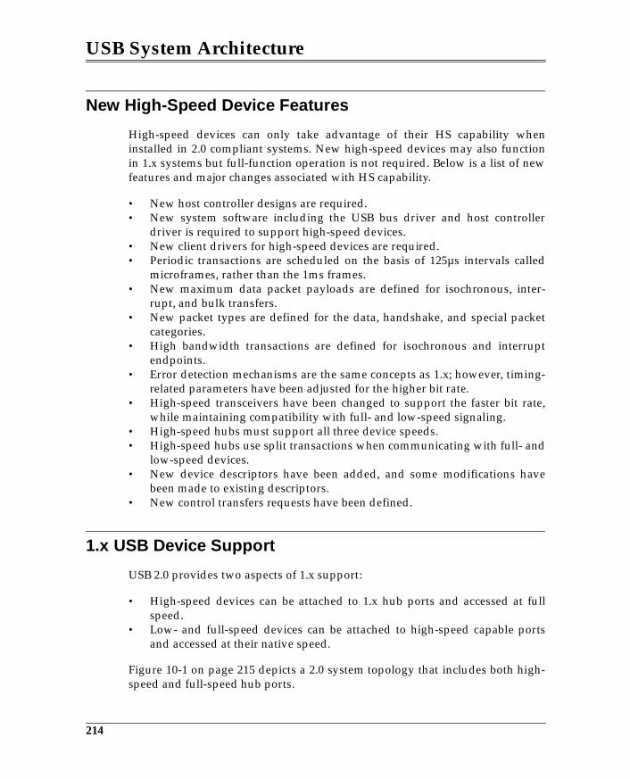
USB System Architecture
New High-Speed Device Features
High-speed devices can only take advantage of their HS capability wheninstalled in 2.0 compliant systems. New high-speed devices may also functionin 1.x systems but full-function operation is not required. Below is a list of newfeatures and major changes associated with HS capability.
• New host controller designs are required.• New system software including the USB bus driver and host controller
driver is required to support high-speed devices.• New client drivers for high-speed devices are required.• Periodic transactions are scheduled on the basis of 125µs intervals called
microframes, rather than the 1ms frames.• New maximum data packet payloads are defined for isochronous, inter-
rupt, and bulk transfers.• New packet types are defined for the data, handshake, and special packet
categories.• High bandwidth transactions are defined for isochronous and interrupt
endpoints.• Error detection mechanisms are the same concepts as 1.x; however, timing-
related parameters have been adjusted for the higher bit rate.• High-speed transceivers have been changed to support the faster bit rate,
while maintaining compatibility with full- and low-speed signaling.• High-speed hubs must support all three device speeds.• High-speed hubs use split transactions when communicating with full- and
low-speed devices.• New device descriptors have been added, and some modifications have
been made to existing descriptors.• New control transfers requests have been defined.
1.x USB Device Support
USB 2.0 provides two aspects of 1.x support:
• High-speed devices can be attached to 1.x hub ports and accessed at fullspeed.
• Low- and full-speed devices can be attached to high-speed capable portsand accessed at their native speed.
Figure 10-1 on page 215 depicts a 2.0 system topology that includes both high-speed and full-speed hub ports.
214
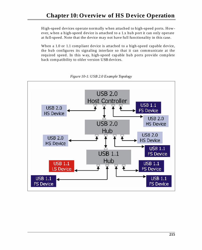
Chapter 10: Overview of HS Device Operation
High-speed devices operate normally when attached to high-speed ports. How-ever, when a high-speed device is attached to a 1.x hub port it can only operateat full-speed. Note that the device may not have full functionality in this case.
When a 1.0 or 1.1 compliant device is attached to a high-speed capable device,the hub configures its signaling interface so that it can communicate at therequired speed. In this way, high-speed capable hub ports provide completeback compatibility to older version USB devices.
Figure 10-1: USB 2.0 Example Topology
215
USB System Architecture
The 2.0 Host Controller
The 2.0 host controller (Enhanced Host Controller Interface) specification wasreleased at the time of this writing. After the host controller specification isreleased, MindShare will document the features and functions of the controllerand make it available for download. See www.mindshare.com for details.
216
11 The High-Speed Signaling Environment
The Previous ChapterThe previous chapter provided a brief introduction to high-speed device opera-tion and was intended to set the stage for a detailed discussion of the high-speed environment starting with this chapter and others that follow.
This ChapterHigh-speed capable devices must also be able to communicate in the full-speedsignaling environment. High-speed devices add many extensions to the full-speed environment to permit reliable signaling at a 480Mb/s rate. This chapterintroduces the principles associated with USB high-speed signaling and themethods used to switch between full- and high-speed operation.
The Next ChapterThe next chapter introduces the changes brought about by the USB 2.0 specifica-tion. The transfers defined in USB 1.0 have the same primary characteristics inthe high-speed environment; however, some changes have been made such asnew packet sizes. Also, new features have been added to the high-speed envi-ronment such as high-bandwidth transfers and the ping protocol. These andother changes are reviewed in this chapter.
Overview
High-speed devices must be able to operate at both full-speed and high-speed.This ability ensures that any high-speed device attached to a 1.x port (i.e., rootports in 1.x system or 1.x hub ports) will work properly. This requirement is
217
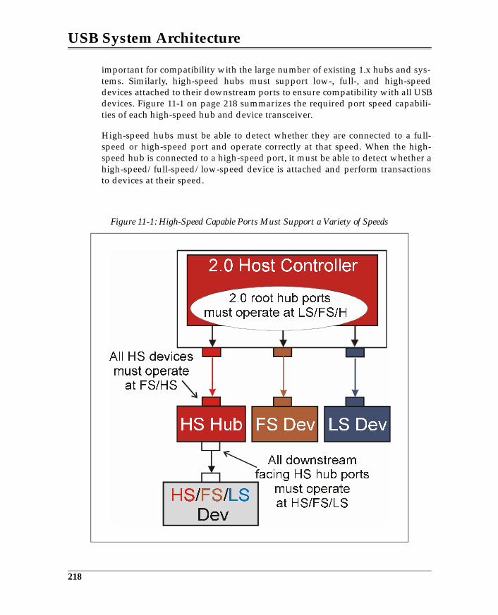
USB System Architecture
important for compatibility with the large number of existing 1.x hubs and sys-tems. Similarly, high-speed hubs must support low-, full-, and high-speeddevices attached to their downstream ports to ensure compatibility with all USBdevices. Figure 11-1 on page 218 summarizes the required port speed capabili-ties of each high-speed hub and device transceiver.
High-speed hubs must be able to detect whether they are connected to a full-speed or high-speed port and operate correctly at that speed. When the high-speed hub is connected to a high-speed port, it must be able to detect whether ahigh-speed/full-speed/low-speed device is attached and perform transactionsto devices at their speed.
Figure 11-1: High-Speed Capable Ports Must Support a Variety of Speeds
218
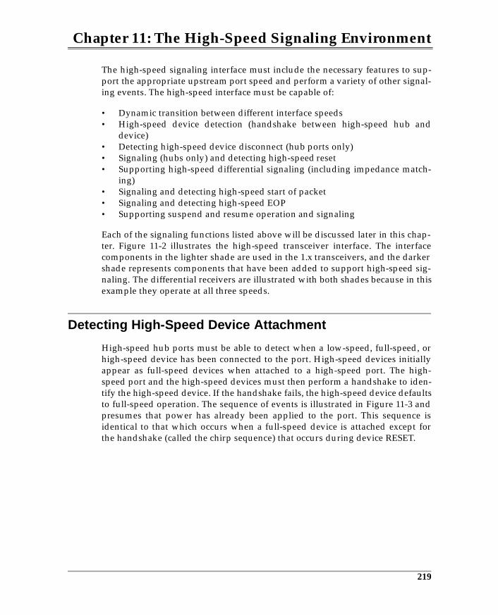
Chapter 11: The High-Speed Signaling Environment
The high-speed signaling interface must include the necessary features to sup-port the appropriate upstream port speed and perform a variety of other signal-ing events. The high-speed interface must be capable of:
• Dynamic transition between different interface speeds• High-speed device detection (handshake between high-speed hub and
device)• Detecting high-speed device disconnect (hub ports only)• Signaling (hubs only) and detecting high-speed reset• Supporting high-speed differential signaling (including impedance match-
ing)• Signaling and detecting high-speed start of packet• Signaling and detecting high-speed EOP• Supporting suspend and resume operation and signaling
Each of the signaling functions listed above will be discussed later in this chap-ter. Figure 11-2 illustrates the high-speed transceiver interface. The interfacecomponents in the lighter shade are used in the 1.x transceivers, and the darkershade represents components that have been added to support high-speed sig-naling. The differential receivers are illustrated with both shades because in thisexample they operate at all three speeds.
Detecting High-Speed Device Attachment
High-speed hub ports must be able to detect when a low-speed, full-speed, orhigh-speed device has been connected to the port. High-speed devices initiallyappear as full-speed devices when attached to a high-speed port. The high-speed port and the high-speed devices must then perform a handshake to iden-tify the high-speed device. If the handshake fails, the high-speed device defaultsto full-speed operation. The sequence of events is illustrated in Figure 11-3 andpresumes that power has already been applied to the port. This sequence isidentical to that which occurs when a full-speed device is attached except forthe handshake (called the chirp sequence) that occurs during device RESET.
219
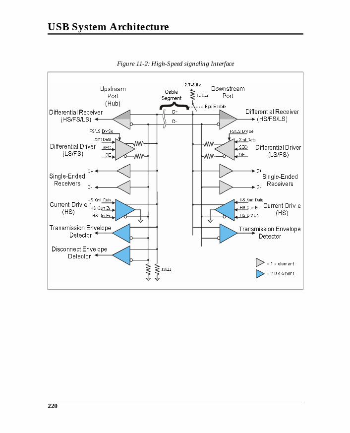
USB System Architecture
Figure 11-2: High-Speed signaling Interface
= 1.x element
= 2.0 element
220
Chapter 11: The High-Speed Signaling Environment
Initial Device Detection
Full- and high-speed devices both have a 1.5KΩ on the D+ line. When thedevice is connected, power is applied to the cable, the device, and the pull-upon D+, causing the voltage to rise above VIH at the hub receiver. Software thenpolls the hub and detects full-speed device attachment.
Device Reset and the Chirp Sequence
After software detects that a full-speed device is connected, it issues RESET tothe hub via the ResetPort command, which causes the hub to drive a SE0 (bothD+ and D- low) for >10ms. If a high-speed capable device is attached, the chirpsequence begins. Figure 11-4 on page 223 depicts the chirp sequence. Each stepin the chirp sequence is detailed in the following enumerated list:
1. Hub drives RESET, which is T0 for the chirp sequence.2. The high-speed device detects RESET and signals a Chirp K. signaling
Figure 11-3: Sequence of Events from Device Connect to High-Speed Operation
221
12 HS Transfers, Transactions, & Scheduling
The Previous ChapterHigh-speed capable devices must also be able to communicate in the full-speedsignaling environment. High-speed devices add many extensions to the full-speed environment to permit reliable signaling at a 480Mb/s rate. The previouschapter introduced the principles associated with USB high-speed signalingand the methods used to switch between full- and high-speed operation.
This ChapterThis chapter introduces the changes brought about by the USB 2.0 specification.The transfers defined in USB 1.0 are also used in 2.0 implementations and havethe same primary characteristics in the high-speed environment; however, somechanges have been made such as new packet sizes. Furthermore, new featureshave been added to the high-speed environment such as high-bandwidth trans-fers and the ping protocol. These and other changes are reviewed in this chap-ter.
The Next ChapterError detection and handling during high-speed transactions is very similar inconcept to the low- and full-speed error detection methods. However, due tothe faster clock rates, several of the timing parameters must be changed to sup-port error detection implementations such as time-out values and babble detect.These issues are discussed in the next chapter.
241
USB System Architecture
Overview
High-speed transfer types are the same as those used by full- and low-speeddevices and include:
• isochronous• interrupt• bulk• control
Although these transfers are the same as those defined by USB 1.x, in somecases the high-speed transactions have new characteristics that are designed toimprove performance. Also, note that high-speed packets differ from their full-speed cousins in the following ways:
1. The synchronization sequence at the beginning of each packet is 4 bytes inlength rather than 1 byte.
2. EOP is 1 byte rather than 2 bits.
Consequently, packet overhead associated with high-speed transaction arehigher.
This chapter describes the characteristics of the high-speed transfers and trans-actions, and describes the mechanisms used for scheduling and executing them.Since isochronous and interrupt transfers have important characteristics incommon, they will be discussed in the section entitled “Periodic Transfers,”while bulk and control transfers are discussed in the section entitled “Non-Peri-odic Transfers.”
High-Speed Transaction Scheduling
All high-speed devices share bus bandwidth when the devices are attached toports of the same controller. High-speed transactions also use the same token,data, and handshake protocol that is used with full- and low-speed transac-tions. Software calculates the time required to perform transactions and sched-ules transactions to be completed during each microframe.
242
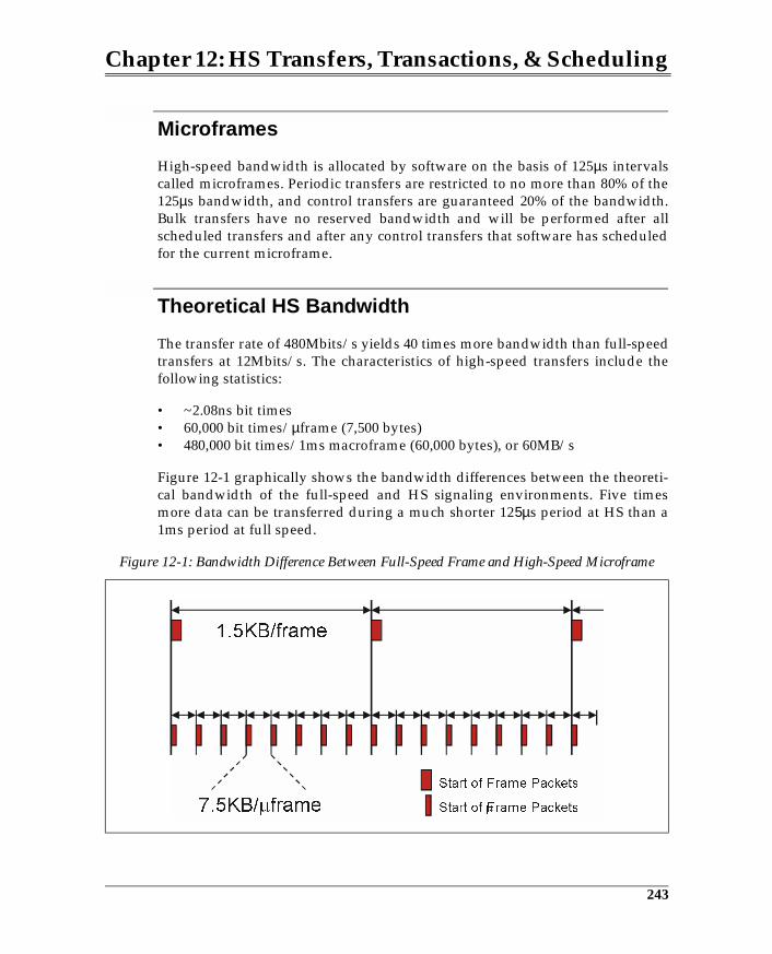
Chapter 12: HS Transfers, Transactions, & Scheduling
Microframes
High-speed bandwidth is allocated by software on the basis of 125µs intervalscalled microframes. Periodic transfers are restricted to no more than 80% of the125µs bandwidth, and control transfers are guaranteed 20% of the bandwidth.Bulk transfers have no reserved bandwidth and will be performed after allscheduled transfers and after any control transfers that software has scheduledfor the current microframe.
Theoretical HS Bandwidth
The transfer rate of 480Mbits/s yields 40 times more bandwidth than full-speedtransfers at 12Mbits/s. The characteristics of high-speed transfers include thefollowing statistics:
• ~2.08ns bit times• 60,000 bit times/µframe (7,500 bytes)• 480,000 bit times/1ms macroframe (60,000 bytes), or 60MB/s
Figure 12-1 graphically shows the bandwidth differences between the theoreti-cal bandwidth of the full-speed and HS signaling environments. Five timesmore data can be transferred during a much shorter 125µs period at HS than a1ms period at full speed.
Figure 12-1: Bandwidth Difference Between Full-Speed Frame and High-Speed Microframe
243
USB System Architecture
The theoretical HS bandwidth of 60MB/s is of course considerably more thanactual data bandwidth. However, greater bus throughput and efficiency is pos-sible with high-speed transfers due to larger packet sizes and new transactionsdefined for high-speed. Note that the same primary packets are used for high-speed, full-speed, and low-speed transactions; thus, the overhead associatedwith the packets themselves remains the same. Bandwidth issues associatedwith each transfer type are discussed in the corresponding sections later in thischapter.
Periodic Transfers
Both isochronous and interrupt transfers must be scheduled on a periodic basis.Isochronous transactions are scheduled every µframe, and interrupt transac-tions occur at specified polling intervals. These transfer types ensure through-put at the periodic rate, making them useful for USB applications that needspecific bandwidth to perform adequately.
High-Speed Isochronous Transfers
Several changes have been made to the isochronous transfer type including:
• Maximum packet size changed from 1023 to 1024 bytes• High bandwidth capability• New data packet types used during high-bandwidth transfers
The following sections discuss these new features and summarize the overallcharacteristics of high-speed transfers.
Maximum Packet Size
Maximum packet size for HS isochronous transactions is 1024 bytes. The maxi-mum packet size for FS isochronous transactions is 1023 bytes. Note that the 2.0specification does not support software requests for isochronous data packets ofzero bytes, but rather reserves a packet size zero encoding for a packet size of1024 bytes.
Isochronous Bandwidth/Performance
A single isochronous transaction is permitted per endpoint during a singleµframe in the standard implementation. The maximum data rate of an isochro-nous transfer is a function of the:
244
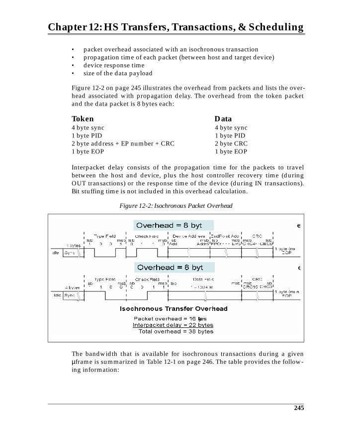
Chapter 12: HS Transfers, Transactions, & Scheduling
• packet overhead associated with an isochronous transaction• propagation time of each packet (between host and target device)• device response time• size of the data payload
Figure 12-2 on page 245 illustrates the overhead from packets and lists the over-head associated with propagation delay. The overhead from the token packetand the data packet is 8 bytes each:
Token Data4 byte sync 4 byte sync1 byte PID 1 byte PID2 byte address + EP number + CRC 2 byte CRC1 byte EOP 1 byte EOP
Interpacket delay consists of the propagation time for the packets to travelbetween the host and device, plus the host controller recovery time (duringOUT transactions) or the response time of the device (during IN transactions).Bit stuffing time is not included in this overhead calculation.
The bandwidth that is available for isochronous transactions during a givenµframe is summarized in Table 12-1 on page 246. The table provides the follow-ing information:
Figure 12-2: Isochronous Packet Overhead
! "
#
%%
& ' ( )
#
245
13 HS Error Detection and Handling
The Previous ChapterThe previous chapter introduces the changes brought about by the USB 2.0specification. The transfers defined in USB 1.0 are also used in 2.0 implementa-tions and have the same primary characteristics in the high-speed environment.However, some changes have been made such as new packet sizes. Further-more, new features have been added to the high-speed environment such ashigh-bandwidth transfers and the ping protocol. These and other changes arereviewed in this chapter.
This ChapterError detection and handling during high-speed transactions are very similar inconcept to the low- and full-speed error detection methods. However, due tothe faster clock rates, several of the timing parameters must be changed to sup-port error detection implementations such as time-out values and babble detect.
The Next ChapterThis chapter discusses the changes required for high-speed devices to use thefull-speed suspend and resume protocol and signaling conventions.
Overview
Error checking and recovery in the high-speed environment can be summarizedas follows:
• same packet error detection as performed by low- and full-speed devices.• transaction time-outs consist of the same round-trip delays, but the some of
265
USB System Architecture
the delays have been changed and delay timing is specified by high-speedbit times rather than low- or full-speed bit times.
• EOF1 and EOF2 babbling device detection uses the same principles asemployed by 1.x hubs, but the EOF points are also referenced to high-speedbit times.
• packet error checking and reporting is modified as necessary to supportsplit transactions.
High-Speed Bus Time-out
Like in the 1.x environment, high-speed devices report packet errors by remain-ing silent when a response is expected. No response is a positive indication tothe device that is awaiting a return packet that the transfer has failed. Theamount of time that a device waits for a response before detecting an error isspecified by the worst-case round-trip delay between the host and target device.Figure 13-1 on page 267 depicts the topology that represents the worst delay.The round-trip delay is specified in high-speed bit times and is based on follow-ing:
• The maximum number of cable hops between host and device = 6• Maximum number of hubs = 5• Maximum response time of function = 192 high-speed bit times• Maximum cable propagation delay = 26ns• Maximum hub delay = 36 bit times + 4ns
The total round-trip delay is calculated as:
• 12 cable crossings * 26ns = 312ns (~150 HS bit times)• 10 hub crossings * 36 bit times + 4ns = 360 bit times + 40ns (~379 HS bit
times)• Maximum response time of function = 192 HS bit times
Total delay = 721 HS bit times
The specification requires that the time-out not occur any earlier than 736 HS bittimes and any later than 816 HS bit times.
266
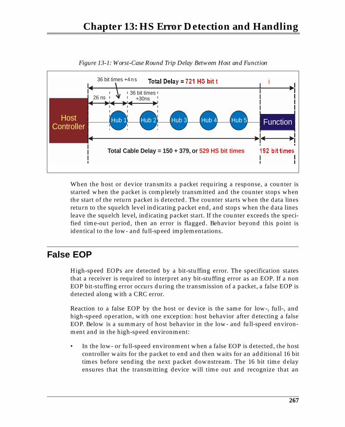
Chapter 13: HS Error Detection and Handling
When the host or device transmits a packet requiring a response, a counter isstarted when the packet is completely transmitted and the counter stops whenthe start of the return packet is detected. The counter starts when the data linesreturn to the squelch level indicating packet end, and stops when the data linesleave the squelch level, indicating packet start. If the counter exceeds the speci-fied time-out period, then an error is flagged. Behavior beyond this point isidentical to the low- and full-speed implementations.
False EOP
High-speed EOPs are detected by a bit-stuffing error. The specification statesthat a receiver is required to interpret any bit-stuffing error as an EOP. If a nonEOP bit-stuffing error occurs during the transmission of a packet, a false EOP isdetected along with a CRC error.
Reaction to a false EOP by the host or device is the same for low-, full-, andhigh-speed operation, with one exception: host behavior after detecting a falseEOP. Below is a summary of host behavior in the low- and full-speed environ-ment and in the high-speed environment:
• In the low- or full-speed environment when a false EOP is detected, the hostcontroller waits for the packet to end and then waits for an additional 16 bittimes before sending the next packet downstream. The 16 bit time delayensures that the transmitting device will time out and recognize that an
Figure 13-1: Worst-Case Round Trip Delay Between Host and Function
HostController Function Hub 1 Hub 2 Hub 3 Hub 4 Hub 5
Total Cable Delay = 150 + 379, or 529 HS bit times
26 ns
36 bit times +4 n s
36 bit times +30ns
267
USB System Architecture
error has occurred in the packet just transmitted.• In the high-speed environment if the host receives a corrupted high-speed
data packet (including false EOP), it ignores any data until the data linesreturn to the squelch level. Upon detecting squelch, the next token packetcan be sent immediately with normal inter-packet delays. Note that duringhigh-speed operation, the host is not required to wait for the device todetect time-out before sending the next packet. In this case, the device hastransferred data to the host and is unaware that a packet error has occurred,so the device is expecting a handshake packet that acknowledges successfultransfer of data. However, the next packet sent by the host is a token packetthat does not target the endpoint that expects the handshake. Since nohandshake is received, the device presumes that the previous packet did nottransfer correctly.
HS Babbling Device Detection
High-speed devices that are babbling or that have lost activity get detected viathe same principle as full-speed implementations. However, the faster trans-mission rate and different signaling states lead to a number of changes.
Figure 13-2 on page 269 illustrates the alignment of frame timers within thehubs. The hub timers are skewed due to the propagation delay associated withthe cable and hub repeaters. This ensures that the EOF1 sample points of eachdownstream hub fall between the EOF1 and EOF2 sample points of the hubimmediately upstream. The specification states that when any hub reaches itsEOF1 sample point, it “tears down upstream connectivity.” If an upstreampacket is being transferred at EOF1, then the upstream port would detect abruptpacket termination, thus ensuring that no upstream packet will be observedwhen the EOF2 point is reached. Note that the hub port to which the babblingdevice is attached will detect upstream activity from the babbling device at itsEOF2 point. The hub must disable the port to prevent it from interfering withthe next microframe.
Note that the proper timing relationships between the EOF points from hub tohub are critical to the detection of a babbling device. The hub designer mustensure that delays associated with SOF decoding are offset by advancing theEOF points so that the timing deltas between EOF1 points are due solely tocable and hub delays.
268
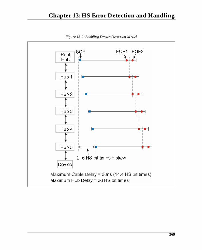
Chapter 13: HS Error Detection and Handling
Figure 13-2: Babbling Device Detection Model
RootHub
Hub 1
Hub 2
Hub 3
Hub 4
Hub 5
Device
EOF2EOF1SOF
Maximum Hub Delay = 36 HS bit times
216 HS bit times + skew
269
14 HS Suspend and Resume
The Previous ChapterError detection and handling during high-speed transactions is very similar inconcept to the low- and full-speed error detection methods. The previous chap-ter discussed the error detection changes that were made in order handle to thefaster clock rates. Several of the timing parameters had to be changed to sup-port error detection implementations such as time-out values and babble detect.
This ChapterThis chapter discusses the changes required for high-speed devices to use thefull-speed suspend and resume protocol and signaling conventions.
The Next ChapterThis chapter introduces the primary characteristics of a high-speed hub. It mustbe able to operate when attached to both full-speed and high-speed ports, andmust support all device speeds on its ports.
Overview
High-speed devices use the full-speed mechanisms for suspend and resume. Inorder to use the full-speed resume signaling, high-speed devices must transi-tion to full-speed operation upon entering suspend and automatically return tohigh-speed signaling when returning to full-power operation. This sectiondescribes the transition from high-speed to full-speed and back.
271
USB System Architecture
Entering Device Suspend
High-speed devices enter the suspend mode after detecting greater than 3ms ofbus idle time, just as 1.x devices do. However, because both bus idle and deviceRESET are signaled via single-ended zero (SE0), additional logic must beemployed to differentiate between these two possibilities. Another elementcommon to both suspend and high-speed RESET is that they transition back tofull-speed signaling.
• Suspend Detection — After 3ms of bus idle time the high-speed deviceknows that it is either being suspended or reset. If a suspend is being sig-naled, then the hub port will signal a full-speed idle (D+ pulled up and D-pulled down).
• RESET Detection — Recall that detecting RESET in the full-speed environ-ment is done after observing a single-ended zero for greater than 2.5µs. Thisdoes not conflict with suspend signaling because bus idle and RESET aresignaled differently. High-speed devices cannot detect RESET after 2.5µs ofSE0 because this could also be a device suspend. If a RESET is being sig-naled by the hub port, then SE0 will continue for >10ms and <20ms.
Figure 14-1 on page 273 illustrates the process of determining whether a devicewill enter suspend or reset. The steps involved in transitioning to suspend areenumerated below:
1. The high-speed device transitions to full-speed operation after observingmore than 3ms but before 3.125ms of HS bus idle. The device re-attaches thepull-up to D+ and turns off its full-speed drivers (thereby removing thehigh-speed terminations).
2. No sooner than 100ms and no later than 875ms after the transition to full-speed operation, the device samples D+ and D- to determine whether sus-pend or RESET is being signaled. If the full-speed bus is in the idle state (Jstate) then the device enters suspend and reduces current draw. If the full-speed bus is in the SE0 state, then the device detects RESET and begins itschirp sequence.
272
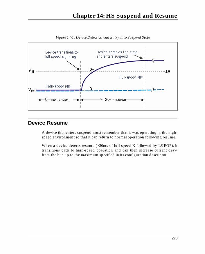
Chapter 14: HS Suspend and Resume
Device Resume
A device that enters suspend must remember that it was operating in the high-speed environment so that it can return to normal operation following resume.
When a device detects resume (>20ms of full-speed K followed by LS EOP), ittransitions back to high-speed operation and can then increase current drawfrom the bus up to the maximum specified in its configuration descriptor.
Figure 14-1: Device Detection and Entry into Suspend State
High-speed idle
Device transitions tofull-speed signaling
Device samples line stateand enters suspend
Full-speed idle
273

USB System Architecture
274
Part Four
USB 2.0 Hub Operation with
LS/FS/HS Devices
Part Four discusses the operation of high-speed hubs. Since USB 2.0 is back-wardly compatible with low-, full-, and high-speed device operation, the issuesassociated with maintaining USB device compatibility is also discussed in PartFour. The chapters and topics included in Part Four are listed below:
• Chapter 15: USB 2.0 Hub Overview• Chapter 16: 2.0 Hub Behavior During HS Transactions• Chapter 17: 2.0 Hub Behavior During LS/FS Transactions
15 HS Hub Overview
The Previous ChapterThe previous chapter discussed the changes required for high-speed devices touse the full-speed suspend and resume protocol and signaling conventions.
This ChapterThis chapter introduces the primary characteristics of a high-speed hub. It mustbe able to operate when attached to both full-speed and high-speed ports, andmust support all device speeds on its ports.
The Next ChapterThe next chapter discusses the 2.0 hub’s behavior when it receives high-speedpackets on its upstream and downstream ports. The chapter also details theoperation of the high-speed repeater and discusses the delays associated withforwarding high-speed packets across the hub.
Overview
The operation of a 2.0 is dependent upon the speed of the upstream port towhich it is attached. If it is attached to a high-speed port, then it enables itshigh-speed repeater and transaction translator logic. The repeater forwards allhigh-speed packets to the high-speed devices attached to the hub’s downstreamfacing ports. The transaction translator handles transactions targeting all low-and full-speed devices attached to the hub’s downstream facing ports.
If the hub attaches to a full-speed port, it must operate as a compliant full-speedhub. The high-speed repeater is disabled and low- and full-speed repeaters areenabled. Also, the transaction translator is disabled in this mode.
277
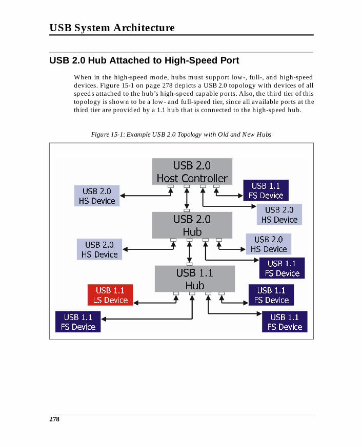
USB System Architecture
USB 2.0 Hub Attached to High-Speed Port
When in the high-speed mode, hubs must support low-, full-, and high-speeddevices. Figure 15-1 on page 278 depicts a USB 2.0 topology with devices of allspeeds attached to the hub’s high-speed capable ports. Also, the third tier of thistopology is shown to be a low- and full-speed tier, since all available ports at thethird tier are provided by a 1.1 hub that is connected to the high-speed hub.
Figure 15-1: Example USB 2.0 Topology with Old and New Hubs
278
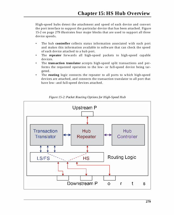
Chapter 15: HS Hub Overview
High-speed hubs detect the attachment and speed of each device and convertthe port interface to support the particular device that has been attached. Figure15-2 on page 279 illustrates four major blocks that are used to support all threedevice speeds.
• The hub controller collects status information associated with each portand makes this information available to software that can check the speedof each device attached to a hub port.
• The repeater forwards all high-speed packets to high-speed capabledevices.
• The transaction translator accepts high-speed split transactions and per-forms the requested operation to the low- or full-speed device being tar-geted.
• The routing logic connects the repeater to all ports to which high-speeddevices are attached, and connects the transaction translator to all port thathave low- and full-speed devices attached.
Figure 15-2: Packet Routing Options for High-Speed Hub
Hub
Controller
Transaction
Translator
Hub
Repeater
HS Routing Logic
Upstream P
Downstream P o r t s
LS/FS
279
USB System Architecture
High-Speed Transactions
The high-speed hub repeater passes all high-speed packets to its high-speedports, including high-speed split transactions. These packets are passed withoutperforming any form of decode. Each packet is re-clocked to the downstreamports. Chapter 16, entitled "2.0 Hubs During HS Transactions," on page 283details the operation of the hub when repeating high-speed packets.
Low- and Full-Speed Transactions
The host issues high-speed split transactions to access low- and full-speeddevices that are attached to high-speed hub ports located downstream from theroot hub (Figure 15-3). The host initiates a transaction via a start-split transac-tion that delivers the token packet to the hub and identifies the hub and portbeing targeted by the transaction. The hub then performs a normal low- or full-speed transaction to the device endpoint. This consists of the normal token,data, and handshake sequence. Depending on whether the transaction is an INor OUT, the host schedules a complete-split transaction to fetch the data orobtain completion status (handshake). Chapter 17, entitled "2.0 Hubs DuringLS/FS Transactions," on page 289 details the operation of hubs when perform-ing split transactions.
280
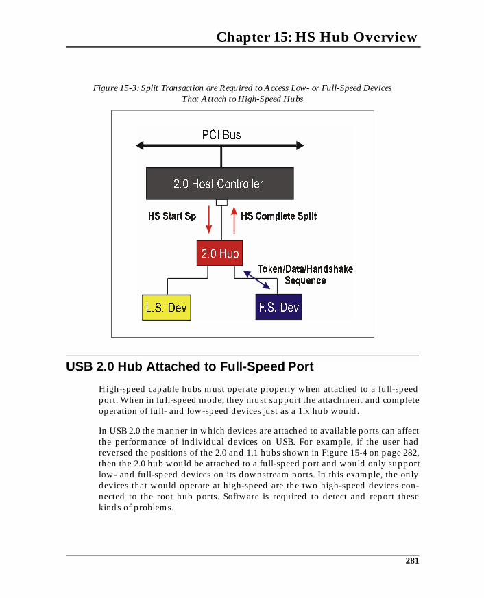
Chapter 15: HS Hub Overview
USB 2.0 Hub Attached to Full-Speed Port
High-speed capable hubs must operate properly when attached to a full-speedport. When in full-speed mode, they must support the attachment and completeoperation of full- and low-speed devices just as a 1.x hub would.
In USB 2.0 the manner in which devices are attached to available ports can affectthe performance of individual devices on USB. For example, if the user hadreversed the positions of the 2.0 and 1.1 hubs shown in Figure 15-4 on page 282,then the 2.0 hub would be attached to a full-speed port and would only supportlow- and full-speed devices on its downstream ports. In this example, the onlydevices that would operate at high-speed are the two high-speed devices con-nected to the root hub ports. Software is required to detect and report thesekinds of problems.
Figure 15-3: Split Transaction are Required to Access Low- or Full-Speed DevicesThat Attach to High-Speed Hubs
2.0 Host Controller
2.0 Hub
L.S. Dev F.S. Dev
PCI Bus
281
16 2.0 Hubs During HS Transactions
The Previous ChapterThe previous chapter introduced the primary characteristics of a high-speedhub, including the ability to operate when attached to both full-speed and high-speed ports and the ability to support all device speeds on its ports.
This Chapter This chapter discusses the 2.0 hub’s behavior when it receives high-speed pack-ets on its upstream and downstream ports. This chapter details the operation ofthe high-speed repeater and discusses the delays associated with forwardinghigh-speed packets across the hub.
The Next ChapterThis chapter introduces the concept of split transactions that allow high-speedhubs to support low- and full-speed devices without sacrificing large amountsof bus time to access the slower devices. The operation of the transaction trans-lator is described, along with the various forms of split transaction and the spe-cific sequences employed by each.
Overview
When a USB 2.0 hub is connected to a high-speed port and has one or morehigh-speed devices attached to its downstream ports, it performs the straight-forward functions of repeating packets in both directions. In this sense the func-tion of a 2.0 hub is no different from a 1.x hub. However, several major differ-ences exist between the two implementations:
1. 2.0 hub receivers have their receivers squelched until a high-speed packet isdetected. Thus time is required to enable the receiver, causing some bits to
283
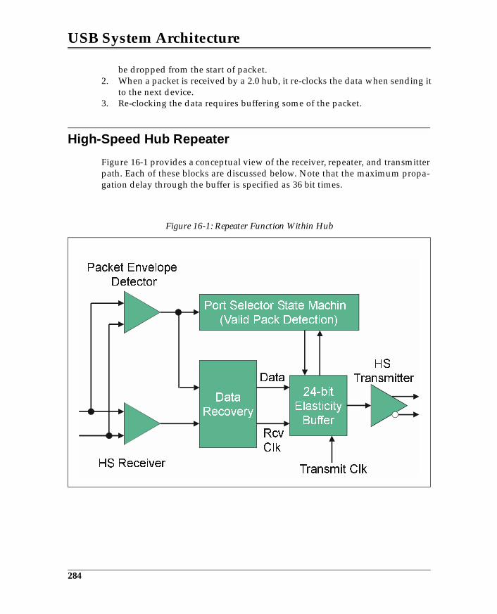
USB System Architecture
be dropped from the start of packet.2. When a packet is received by a 2.0 hub, it re-clocks the data when sending it
to the next device.3. Re-clocking the data requires buffering some of the packet.
High-Speed Hub Repeater
Figure 16-1 provides a conceptual view of the receiver, repeater, and transmitterpath. Each of these blocks are discussed below. Note that the maximum propa-gation delay through the buffer is specified as 36 bit times.
Figure 16-1: Repeater Function Within Hub
!"# $
%
%
284
Chapter 16: 2.0 Hubs During HS Transactions
Receiver Squelch
As described in Chapter 11, high-speed receive circuitry is squelched when thebus is idle and enabled when a differential voltage of 150mv is detected by thepacket envelope detector. The hub specification allows up to 4 bit timesbetween detecting the packet and enabling the receiver. Thus, the first 4 bits ofeach packet can be dropped by a hub. This results in the synchronization clockbeing reduced by as many as 4 bits. Since the maximum number of hubsbetween any USB device and the root hub is 5, the maximum number of syn-chronization bits dropped is 20 out of the 32 produced at the originator.
The same 4 bit times affect the end of packet as well. When the receiving portreturns to the idle state, the repeater is disabled; however, it may take up to 4 bittimes to actually disable the repeater after EOP. This results in up to 4 randombits added to the end of the packet. These bits are termed dribble bits, but haveno adverse effect on the detection of the packet at the receiver. They will accu-mulate with each hub crossing so that the fifth hub may send a packet with amaximum of 20 dribble bits. When the receiver of this packet detects EOP (via abit stuffing error), it will check CRC and detect a valid value and the followingdribble bits are simply discarded.
Re-clocking the Packet
Re-clocking packets is performed to reduce the jitter seen at a receiver so that jit-ter remains within the limits defined by the specification. Re-clocking involvesextracting the data from the received NRZI stream and re-transmitting thestream using the hub’s local clock.
Port Selector State Machine
The block represents a hub state machine whose job it is to verify that theincoming packet is valid. The state machine detects removal of squelch (whichcould be caused by noise) and awaits the priming of the elasticity buffer (12 bittimes). The state machine then checks for the repeating pattern of “JK” or “KJ”within the elasticity buffer, which indicates the synchronization pattern and avalid packet. If no repeating pattern is detected, then transmission of the packetto the downstream ports is not enabled.
285
USB System Architecture
Elasticity Buffer
The elasticity buffer handles the frequency differences between the receiveclock derived from the receive packet and transmit clock generated locallywithin the hub. The specification allows clock tolerance of 500ppm, resulting inthe maximum difference between the receive and transmit clocks of 1000ppm.The elasticity buffer must handle the case where the receive clock is faster thanthe transmit clock and vice versa. To handle both conditions, the buffer must befilled half-way (primed) before data is clocked out of the buffer. In this way, ifdata is taken out of the buffer more quickly than it is being filled, no underrunwill occur, and buffer space is also available to prevent overflow when data isstored faster than it is taken out.
The half-depth of the buffer must be equal to the maximum difference in clockrate over the length of a maximum-sized packet. Calculation of the half-depthof the buffer is as follows:
• given that the maximum clock difference is 1000ppm, and• the maximum packet length is: 1024 byte data payload + total overhead
including 20 dribble bits = 9644 bits;• then the maximum overrun or underrun is approximately 10 bits (1000ppm
* 9644 = 9.644 bits).
The specification requires a buffer half-depth of 12 bits to provide 2 bits of addi-tional margin.
The Repeater State Machine
The hub repeater states are the same for low-, full-, and high-speed hub opera-tion (See Figure 16-2 on page 287). However, when a hub is operating at high-speed, it repeats only high-speed packets. The operation of the high-speed statemachine includes the following characteristics:
• Connectivity is established upon detecting a Start of High-Speed Packet(SOHP). Transitions caused by SOHP occur when the port selector statemachine has ensured that a valid packet has been detected. See Figure 16-1on page 284.
• Connectivity is torn down upon detecting a High-Speed End Of Packet(HEOP). The state transitions take place after the hub has repeated the lastbit in the elasticity buffer.
286
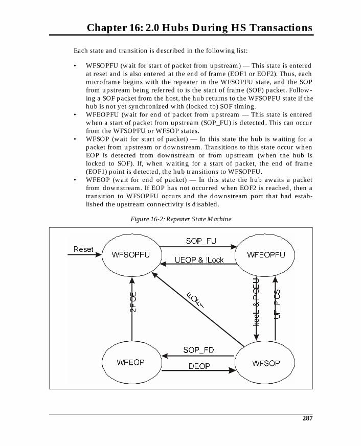
Chapter 16: 2.0 Hubs During HS Transactions
Each state and transition is described in the following list:
• WFSOPFU (wait for start of packet from upstream) — This state is enteredat reset and is also entered at the end of frame (EOF1 or EOF2). Thus, eachmicroframe begins with the repeater in the WFSOPFU state, and the SOPfrom upstream being referred to is the start of frame (SOF) packet. Follow-ing a SOF packet from the host, the hub returns to the WFSOPFU state if thehub is not yet synchronized with (locked to) SOF timing.
• WFEOPFU (wait for end of packet from upstream — This state is enteredwhen a start of packet from upstream (SOP_FU) is detected. This can occurfrom the WFSOPFU or WFSOP states.
• WFSOP (wait for start of packet) — In this state the hub is waiting for apacket from upstream or downstream. Transitions to this state occur whenEOP is detected from downstream or from upstream (when the hub islocked to SOF). If, when waiting for a start of packet, the end of frame(EOF1) point is detected, the hub transitions to WFSOPFU.
• WFEOP (wait for end of packet) — In this state the hub awaits a packetfrom downstream. If EOP has not occurred when EOF2 is reached, then atransition to WFSOPFU occurs and the downstream port that had estab-lished the upstream connectivity is disabled.
Figure 16-2: Repeater State Machine
287
17 2.0 Hubs During LS/FS Transactions
The Previous ChapterThe previous chapter discussed the 2.0 hub’s behavior when it receives high-speed packets on its upstream and downstream ports. The chapter also detailedthe operation of the high-speed repeater and discussed the delays associatedwith forwarding high-speed packets across the hub.
This ChapterThis chapter introduces the concept of split transactions that allow high-speedhubs to support low- and full-speed devices without sacrificing large amountsof bus time to access the slower devices. The operation of the transaction trans-lator is described, along with the various forms of split transaction and the spe-cific sequences employed by each.
The Next ChapterThis chapter provides an overview of the configuration process. Each of themajor steps involved in USB device enumeration are defined and discussed.
Overview
High-speed hubs must translate split transactions into either low- or full-speedtransactions as discussed previously. This chapter details the operation of thehub and specifically the transaction translator that handles the conversion ofhigh-speed packets to low- or full-speed. Figure 17-1 on page 290 illustrates thepacket flow through a high-speed hub with low-, full- and high-speed devicesattached to the hub’s downstream port. Split transactions are handled by thetransaction translator, resulting in a low- or full-speed transaction to the targethub port, while all high-speed packets (including split transactions) arerepeated to the high-speed port.
289
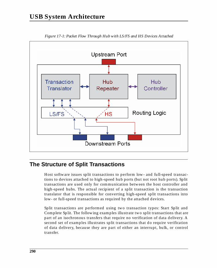
USB System Architecture
The Structure of Split Transactions
Host software issues split transactions to perform low- and full-speed transac-tions to devices attached to high-speed hub ports (but not root hub ports). Splittransactions are used only for communication between the host controller andhigh-speed hubs. The actual recipient of a split transaction is the transactiontranslator that is responsible for converting high-speed split transactions intolow- or full-speed transactions as required by the attached devices.
Split transactions are performed using two transaction types: Start Split andComplete Split. The following examples illustrate two split transactions that arepart of an isochronous transfers that require no verification of data delivery. Asecond set of examples illustrates split transactions that do require verificationof data delivery, because they are part of either an interrupt, bulk, or controltransfer.
Figure 17-1: Packet Flow Through Hub with LS/FS and HS Devices Attached
290
Chapter 17: 2.0 Hubs During LS/FS Transactions
Isochronous Split Transaction Examples
The two examples that follow each describe the sequence of packets used by thehost to perform an isochronous split transaction that has a relatively large datapayload. In both cases, the data payload size is sufficiently large that the datatransfer requires multiple microframes to complete. The first example is an iso-chronous OUT transaction and the second is an isochronous IN transaction.
Example Split Isochronous OUT Transaction
Figure 17-2 on page 292 depicts the sequence of start split (SS) transactions asso-ciated with a lengthy isochronous OUT transaction. The first start split initiatesthe transaction and delivers the first block of data. Each microframe carries dataat high speed that the hub will deliver to the full-speed bus during the nextmicroframe interval. The data is delivered to the hub just in time for deliveryacross the full-speed bus during the following microframe interval. Thismethod of delivering data has two benefits:
1. the data buffers within the hub can be smaller.2. the distribution of data across multiple microframes keeps the bandwidth
evened out across these frames, thereby making more bandwidth availableto periodic transactions while meeting the needs of the full-speed bus.
Because no verification of data delivery is required during isochronous transac-tions, no complete split transaction is used in this case.
291
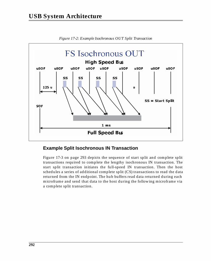
USB System Architecture
Example Split Isochronous IN Transaction
Figure 17-3 on page 293 depicts the sequence of start split and complete splittransactions required to complete the lengthy isochronous IN transaction. Thestart split transaction initiates the full-speed IN transaction. Then the hostschedules a series of additional complete split (CS) transactions to read the datareturned from the IN endpoint. The hub buffers read data returned during eachmicroframe and send that data to the host during the following microframe viaa complete split transaction.
Figure 17-2: Example Isochronous OUT Split Transaction
292
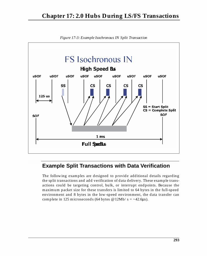
Chapter 17: 2.0 Hubs During LS/FS Transactions
Example Split Transactions with Data Verification
The following examples are designed to provide additional details regardingthe split transactions and add verification of data delivery. These example trans-actions could be targeting control, bulk, or interrupt endpoints. Because themaximum packet size for these transfers is limited to 64 bytes in the full-speedenvironment and 8 bytes in the low-speed environment, the data transfer cancomplete in 125 microseconds (64 bytes @ 12Mb/s = ~42.6µs).
Figure 17-3: Example Isochronous IN Split Transaction
uSOF
SOF
uSOFuSOFuSOFuSOFuSOF
SOF
uSOFuSOF uSOF
125 us
SS = Start Split
293
18 Configuration Process
The Previous ChapterThe previous chapter introduced the concept of split transactions that allowhigh-speed hubs to support low- and full-speed devices without sacrificinglarge amounts of bus time to access the slower devices. The operation of thetransaction translator was also described, along with the various forms of splittransaction and the specific sequences employed by each.
This ChapterThis chapter provides an overview of the configuration process. Each of themajor steps involved in USB device enumeration are defined and discussed.
The Next ChapterThis chapter discusses configuration of USB devices that are attached to anyUSB port. The process is virtually the same for devices of any speed. Devicedescriptors and other characteristics and features that relate to configuring thedevice are also detailed and discussed.
Overview
Host software is responsible for detecting and configuring all devices attachedto the root hub. The process of identifying and configuring a USB device is com-monly referred to as USB device enumeration. Device enumeration begins atthe root hub. Each hub port must be reset and enabled in turn. When powered,the hub determines if a low-, full-, or high-speed device is attached or no deviceat all. If a device is present, status bits within the root hub are set to reflectdevice attachment. Software recognizes that a device is attached, enables theport, resets the USB device, assigns a unique address, and completes the config-uration. This operation is performed for each port until all devices attached tothe root hub have been identified and configured.
339
USB System Architecture
The discussion in this chapter presumes that software has already initialized theUSB host controller and that it is capable of generating USB transactions.
Different operating systems will define different software components involvedin USB device configuration and will perform configuration in their own partic-ular sequence. The following discussions identify the primary steps involved inthe configuration process, but should not be interpreted as the specific sequencethat is followed by a given host software solution. The following list specifiesactions taken by host software and the root hub when configuring a device thatis connected to a root hub port:
• Host requests power be applied to the ports, if not already powered.• Hub detects device attachment and device speed, and sets status bits.• Host polls hub and identifies that a device is attached.• Host issues reset to port/USB device (minimum of 10ms). Chirp is per-
formed during reset if a high-speed device is attached.• Host checks hub status again if the device originally reported full-speed
operation. This is done to see if the device is now operating at high speed.• USB device now answers to default address (zero).• Host performs GetDescriptor requests to fetch the standard descriptors that
contain configuration information. These descriptors are parsed by soft-ware to determine the characteristics of the device. The configuration infor-mation includes bus power and bus bandwidth requirements, and deviceclass information.
• Host assigns unique address to USB device.• Host verifies that the USB resources needed by the device are available.• Host issues a configuration value to the USB device specifying how it’s to
be used. When the configuration value is received, the device assumes thecharacteristics that it reported via the descriptors. The device is now readyto be accessed by client software and can draw the amount of bus powerdescribed in the configuration.
The operations performed above are primarily accomplished via control trans-fers. Software uses each device’s control endpoint (endpoint zero) to access itsdescriptors and to configure the device. (The mechanisms used for performingcontrol transfers to a device are described in the following chapters.)
The following sections provide an overview of the configuration process. Moredetail regarding device configuration can be found in the following chapters.
340
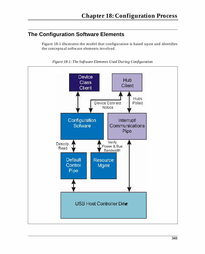
Chapter 18: Configuration Process
The Configuration Software Elements
Figure 18-1 illustrates the model that configuration is based upon and identifiesthe conceptual software elements involved.
Figure 18-1: The Software Elements Used During Configuration
341
USB System Architecture
USB Host Controller Driver
This software is typically the first USB-specific software to execute. The hostcontroller must be initialized by this driver before USB becomes active. Duringconfiguration this driver also performs accesses to root hub status and controlregisters under the direction of the hub client.
Configuration Software
The hub client must notify configuration software that a new device has beenattached. In response, configuration software must identify the newly attacheddevice by reading its standard descriptors, using the default control pipe. Infor-mation read from the descriptors specifies the USB resources that are requiredby the device (e.g., bus bandwidth and power requirements). These descriptorsmust be interpreted by configuration software.
A device can support more than one configuration, requiring software to selectthe configuration of choice. Each configuration provides alternatives for config-uring the device. For example, a device may support both high-power and low-power configurations. That is, if the hub port cannot support a high-powerfunction, then configuration software could select the low-power configuration.Note that the client driver may also be involved in selecting the configuration.
Configuration software assigns a unique device address to the device and com-pletes its hardware configuration by assigning a configuration to the device.When the configuration is assigned, the device is enabled and ready for opera-tion.
The configuration software then finds the client driver software for this devicebased on its class or vendor-specific information that was previously read fromthe standard descriptors.
Default Control Pipe
The default control pipe accesses endpoint zero within each device. The hub cli-ent, configuration software, and device client software all share access to thiscommunications pipe. The host system software is the default owner of thepipe; thus, hub clients and other device client drivers must request its use.
342
Chapter 18: Configuration Process
Resource Management
Configuration software must ensure that the available USB resources can sup-port the device configuration that is selected. Resource management softwaremust track the bus bandwidth consumed by all USB devices as they are config-ured. As each device is attached, resource management software must verifythat the periodic endpoints can be supported based on their bandwidth needsand the bandwidth that remains.
Device bus power requirements must also be checked against the power avail-able at the port to which the device is attached. Power available at a hub portmust be determined by the hub client, because it has specific knowledge of thepower characteristics of the hub. Port power capacity is requested by resourcemanagement software so that it can verify power requirements can be met.
If USB can provide the bus power and bandwidth needed by the device, thenthe device can be configured. If the USB cannot support the requested configu-ration, then alternate device configurations are checked; if none of the configu-rations can be supported, the device is not configured and the user is notified.
Device Client Software
Once configuration software has configured the device it is ready for operationfrom the hardware perspective. Client software is identified by configurationsoftware and loaded. This software must read client-specific and/or class-spe-cific descriptors to verify its capabilities. Client software can then initialize thedevice for use by the application layer.
Root Hub Configuration
Host software begins USB device enumeration by configuring the root hub. Theroot hub must implement a status change endpoint (see Figure 18-2) that can beused by the hub client to detect status changes pertaining to each port. Once thehub is configured, software can poll the status change endpoint to detect whichports currently have devices attached to them.
343
19 USB Device Configuration
The Previous ChapterThe previous chapter provided an overview of the configuration process. Eachof the major steps involved in USB device enumeration were defined and dis-cussed.
This Chapter
This chapter discusses configuration of USB devices that are attached to anyUSB port. The process is virtually the same for devices of any speed. Devicedescriptors and other characteristics and features that relate to configuring thedevice are also detailed and discussed.
The Next ChapterHub devices are configured like any other device attached to a USB port. Hubconfiguration differs in that it involves reporting whether or not other devicesare attached to the downstream ports. The next chapter reviews the hub config-uration process with the focus on the issues related to extending the busthrough the hub’s downstream facing ports.
Overview
During system boot and initialization, all USB hubs and devices will be detectedand configured. Following initialization, devices may be detached or newdevices may be connected. The hub client periodically polls all USB hubs todetect device attachment or detachment. If a status change results from a newdevice having been attached, the configuration process is triggered.
347
USB System Architecture
Summary of Configuration Process
Prior to configuring a device, the hub to which the device is attached must havealready been configured and power must be applied to the port. Next, the huband configuration software must detect the connected device:
• The hub recognizes that a device has been attached by monitoring the D-and D+ port signals.
• The hub sets status information for the port indicating device connect andspeed.
• Configuration software reads port status and recognizes that a full-speeddevice is connected.
• Software then enables the port so that the hub will pass bus traffic to thedevice.
• Configuration software then issues a Reset Port request, forcing the deviceinto its default state. In the default state the device is unconfigured andresponds only to accesses targeted for device zero and endpoint zero.
Configuration software can now begin the device configuration process. Thisprocess is similar to that used when configuring a hub.
• Host queries device’s control endpoint (zero) at address zero to determinemaximum payload supported by the default pipe.
• Host assigns unique address to USB device.• Host reads and evaluates configuration information from descriptors.• Host verifies that the USB resources needed by the device are available.• Host issues a configuration value to USB device specifying how it’s to be
used. When the configuration value is received, the device assumes itsdescribed characteristics. Device is now ready to be accessed by client soft-ware and can draw the amount of Vbus power described in the configura-tion.
How Software Detects Device Attachment & Speed
Hubs have specific knowledge of whether a device has been attached to one oftheir ports only when the port is powered. The software responsible for apply-ing power to a hub port, for detecting that a device is attached to a port, forresetting the port, etc. is, of course, the hub client software. This software playsa pivotal role in device configuration. This section deals with how the hub clientdetermines that a device is attached to a port and the speed at which it operates.
348
Chapter 19: USB Device Configuration
Configuration always begins at the root hub. The host controller driver actuallyperforms the low-level accesses to registers within the controller to determinewhether a device is attached to one of the root ports. However, the host control-ler driver software must create an abstraction of the regular USB hub so that thehub client can make requests to the host controller just as it does when access-ing USB hubs. Because of this abstraction, the same process is described for boththe root hub and USB hubs that reside on the USB. The actual mechanisms usedto access status information is different, but only the USB mechanisms aredescribed. This is because the host controller driver uses conventional memoryor I/O transactions to read root hub status, whereas USB endpoints must beaccessed to obtain status from other USB hubs.
Polling the Status Change Endpoint
The first step in determining whether a device has been attached to a port is forthe hub client to poll the hub’s status change endpoint. Hubs implement aninterrupt endpoint that keeps track of status change events by setting statusbits. Figure 19-1 illustrates the definition of the information returned by the sta-tus change endpoint. Configuration software is aware of the number of portssupported by each hub, and therefore is aware of the size of the bitmap returnedwhen the hub’s status change endpoint is polled. Status is reported in byte-sized fields with zeros returned in the bit fields corresponding to ports that arenot implemented. For most implementations a byte will be returned becausehubs rarely have more than 7 ports.
When software polls the status change endpoint, the bitmap illustrated in Fig-ure 19-1 is returned only if a status change has occurred. If, when polling thestatus change endpoint, it returns NAK during the IN transaction, then none ofthe bits are set, and no changes need to be reported.
To move ahead with the discussion, we must presume that at least one of theport bits is set. Upon detecting that a bit is set, the hub client must read statusinformation from the port. This requires use of a control transfer.
349
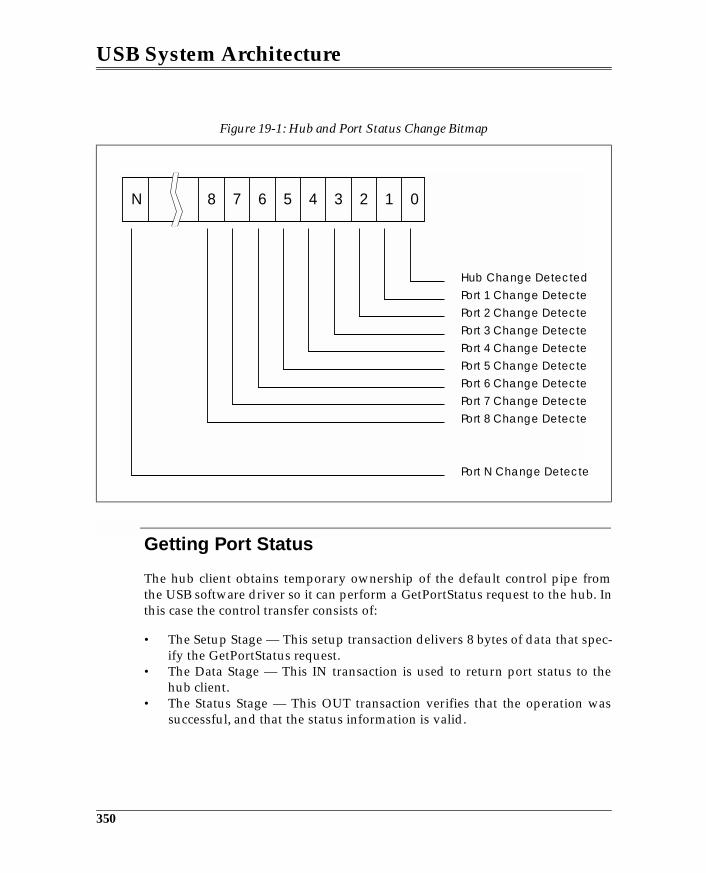
USB System Architecture
Getting Port Status
The hub client obtains temporary ownership of the default control pipe fromthe USB software driver so it can perform a GetPortStatus request to the hub. Inthis case the control transfer consists of:
• The Setup Stage — This setup transaction delivers 8 bytes of data that spec-ify the GetPortStatus request.
• The Data Stage — This IN transaction is used to return port status to thehub client.
• The Status Stage — This OUT transaction verifies that the operation wassuccessful, and that the status information is valid.
Figure 19-1: Hub and Port Status Change Bitmap
012345678N
Hub Change Detected
Port 1 Change Detecte
Port 2 Change Detecte
Port 3 Change Detecte
Port 4 Change Detecte
Port 5 Change Detecte
Port 6 Change Detecte
Port 7 Change Detecte
Port 8 Change Detecte
Port N Change Detecte
350
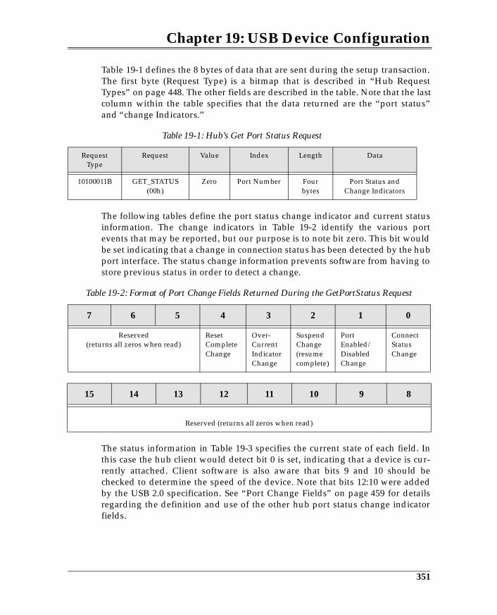
Chapter 19: USB Device Configuration
Table 19-1 defines the 8 bytes of data that are sent during the setup transaction.The first byte (Request Type) is a bitmap that is described in “Hub RequestTypes” on page 448. The other fields are described in the table. Note that the lastcolumn within the table specifies that the data returned are the “port status”and “change Indicators.”
The following tables define the port status change indicator and current statusinformation. The change indicators in Table 19-2 identify the various portevents that may be reported, but our purpose is to note bit zero. This bit wouldbe set indicating that a change in connection status has been detected by the hubport interface. The status change information prevents software from having tostore previous status in order to detect a change.
The status information in Table 19-3 specifies the current state of each field. Inthis case the hub client would detect bit 0 is set, indicating that a device is cur-rently attached. Client software is also aware that bits 9 and 10 should bechecked to determine the speed of the device. Note that bits 12:10 were addedby the USB 2.0 specification. See “Port Change Fields” on page 459 for detailsregarding the definition and use of the other hub port status change indicatorfields.
Table 19-1: Hub’s Get Port Status Request
RequestType
Request Value Index Length Data
10100011B GET_STATUS(00h)
Zero Port Number Four bytes
Port Status and Change Indicators
Table 19-2: Format of Port Change Fields Returned During the GetPortStatus Request
7 6 5 4 3 2 1 0
Reserved(returns all zeros when read)
Reset Complete Change
Over-Current IndicatorChange
Suspend Change(resume complete)
Port Enabled/DisabledChange
ConnectStatusChange
15 14 13 12 11 10 9 8
Reserved (returns all zeros when read)
351
20 Hub Configuration
The Previous ChapterThe previous chapter discussed the configuration of USB devices that areattached to any USB port. The process is virtually the same for devices of anyspeed. Device descriptors and other characteristics and features that relate toconfiguring the device were also detailed and discussed.
This ChapterHub devices are configured like any other device attached to a USB port. Hubconfiguration differs in that it involves reporting whether or not other devicesare attached to the downstream ports. This chapter reviews the hub configura-tion process with the focus on the issues related to extending the bus throughthe hub’s downstream facing ports.
The Next ChapterThe next chapter introduces the concept of device classes and discusses theirrole within the USB. This chapter also introduces all the approved class types (atthe time of this writing) and provides a more detailed summary of the audio,mass storage, monitor, and communications classes. These classes are discussedto provide the reader with a sense of the information defined for each class andthe USB mechanisms that they use. A detailed discussion of device classesrequires in-depth knowledge in the associated field such as telephony andaudio, and is outside the scope of this book.
375
USB System Architecture
Configuring the Hub
Hubs must be configured like any other device, but this also involves identify-ing other devices that may be attached to the port. The steps taken by configura-tion software include:
• Reading the standard device descriptors to obtain a variety of informationneeded to configure the device.
• Assigning a unique address to the hub.• Powering the ports.• Checking the hub status change endpoint to detect port events.• Reading status information to determine the nature of the event.• Enabling the port to provide access to the attached device.
As indicated above, a hub must implement a status change port in addition tothe default port. Figure 20-1 illustrates the required hub endpoints. The defaultcontrol port provides access to the descriptors that define the type of devicerequiring configuration. A hub may also be implemented as part of a com-pound device; hence, the descriptors may describe additional functions beyondthe minimum required of the hub alone.
The Default Pipe
All devices, including hubs, have a default control pipe at endpoint zero. Hostsoftware owns the default control pipe that is used to configure hubs and USBdevices. This communications pipe is established during initialization so thatUSB devices can be accessed based on established defaults. The configurationprocess requires numerous default pipe accesses for configuring and control-ling hub features, including: reading the device descriptors, powering hubports, resetting ports, reading port status, and enabling ports.
The Status Change Pipe
Hubs must implement a status change endpoint that can be polled to detect sta-tus changes that have occurred at the hub ports (e.g., device attachment anddetachment). Note that the status endpoint provides status information for allhub ports. Configuration software determines the characteristics and the end-point number of the status change register by reading the endpoint descriptor.
376
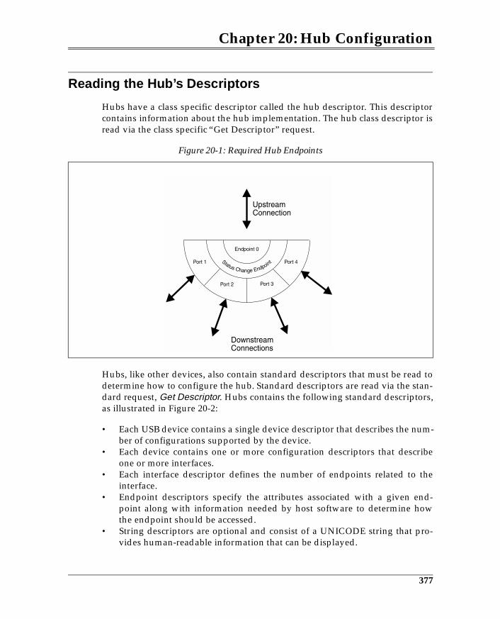
Chapter 20: Hub Configuration
Reading the Hub’s Descriptors
Hubs have a class specific descriptor called the hub descriptor. This descriptorcontains information about the hub implementation. The hub class descriptor isread via the class specific “Get Descriptor” request.
Hubs, like other devices, also contain standard descriptors that must be read todetermine how to configure the hub. Standard descriptors are read via the stan-dard request, Get Descriptor. Hubs contains the following standard descriptors,as illustrated in Figure 20-2:
• Each USB device contains a single device descriptor that describes the num-ber of configurations supported by the device.
• Each device contains one or more configuration descriptors that describeone or more interfaces.
• Each interface descriptor defines the number of endpoints related to theinterface.
• Endpoint descriptors specify the attributes associated with a given end-point along with information needed by host software to determine howthe endpoint should be accessed.
• String descriptors are optional and consist of a UNICODE string that pro-vides human-readable information that can be displayed.
Figure 20-1: Required Hub Endpoints
377
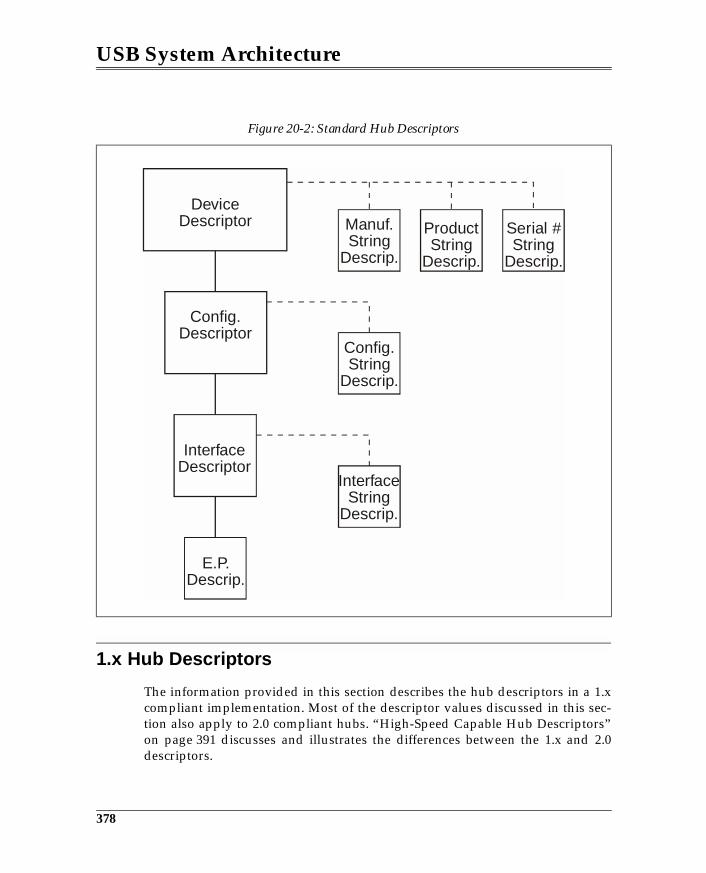
USB System Architecture
1.x Hub Descriptors
The information provided in this section describes the hub descriptors in a 1.xcompliant implementation. Most of the descriptor values discussed in this sec-tion also apply to 2.0 compliant hubs. “High-Speed Capable Hub Descriptors”on page 391 discusses and illustrates the differences between the 1.x and 2.0descriptors.
Figure 20-2: Standard Hub Descriptors
DeviceDescriptor
Config.Descriptor
InterfaceDescriptor
E.P.Descrip.
Manuf.String
Descrip.
Config.String
Descrip.
InterfaceString
Descrip.
ProductString
Descrip.
Serial #String
Descrip.
378
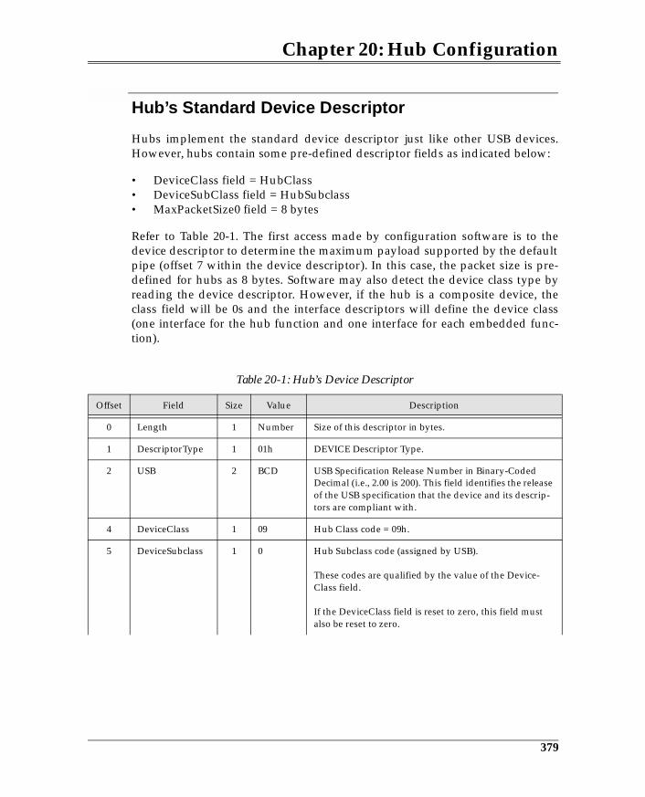
Chapter 20: Hub Configuration
Hub’s Standard Device Descriptor
Hubs implement the standard device descriptor just like other USB devices.However, hubs contain some pre-defined descriptor fields as indicated below:
• DeviceClass field = HubClass • DeviceSubClass field = HubSubclass • MaxPacketSize0 field = 8 bytes
Refer to Table 20-1. The first access made by configuration software is to thedevice descriptor to determine the maximum payload supported by the defaultpipe (offset 7 within the device descriptor). In this case, the packet size is pre-defined for hubs as 8 bytes. Software may also detect the device class type byreading the device descriptor. However, if the hub is a composite device, theclass field will be 0s and the interface descriptors will define the device class(one interface for the hub function and one interface for each embedded func-tion).
Table 20-1: Hub’s Device Descriptor
Offset Field Size Value Description
0 Length 1 Number Size of this descriptor in bytes.
1 DescriptorType 1 01h DEVICE Descriptor Type.
2 USB 2 BCD USB Specification Release Number in Binary-Coded Decimal (i.e., 2.00 is 200). This field identifies the release of the USB specification that the device and its descrip-tors are compliant with.
4 DeviceClass 1 09 Hub Class code = 09h.
5 DeviceSubclass 1 0 Hub Subclass code (assigned by USB).
These codes are qualified by the value of the Device-Class field.
If the DeviceClass field is reset to zero, this field must also be reset to zero.
379
21 Device Classes
The Previous ChapterHub devices are configured like any other device attached to a USB port. Hubconfiguration differs in that it involves reporting whether or not other devicesare attached to the downstream ports. The previous chapter reviewed the hubconfiguration process with the focus on the issues related to extending the busthrough the hub’s downstream facing ports.
This ChapterThis chapter introduces the concept of device classes and discusses their rolewithin the USB. This chapter introduces the class types and provides a moredetailed summary of the audio, mass storage, monitor, and communicationsclasses. These classes are discussed to provide the reader with a sense of theinformation defined for each class and the USB mechanisms that they use. Adetailed discussion of device classes requires in-depth knowledge in the associ-ated field such as telephony and audio, and is outside the scope of this book.
The Next ChapterHost software consists of three types of components: the USB device drivers, theUSB driver, and the host controller driver. This chapter discusses the role ofeach of these layers and describes the requirements of their programming inter-faces.
Overview
Device classes are intended to permit a device driver design that can manipu-late a set of devices that have similar attributes and services. A given class defi-nition can further describe the individual characteristics of particular devicetypes within the class, thereby providing the USB device driver with the infor-mation it needs to manipulate the device as required.
403
USB System Architecture
Device class definition relates to a functional interface used to access and con-trol a particular class of device. For example, Figure 21-1 on page 405 illustratesa USB CD-ROM device with two interfaces: mass storage and audio. Devicesthat support two or more functions are called composite devices and require anindividual programming interface for each function of a given class. A massstorage class driver is required to use the CD-ROM for reading files from a pro-gram disk, while the audio class device driver is required to play a music CD.Each driver accesses the collection of endpoints that constitute the status, con-trol, and data interface(s) for the device class.
Note that the USB components that are device class specific are the functionalinterface and the USB device driver. The descriptors associated with a devicespecify several items that relate to device class definitions, including:
• Device Class Code field — from each functional interface descriptor.• Sub Class Code field — the definition of this field is device class specific.• Protocol field — this optional field may be defined for a given device class
and subclass to define some element of the programming interface sup-ported by the device.
The device class code fields can be used by host software to locate the appropri-ate device driver needed to access a device’s functional interface. All other stan-dard descriptor information is related to USB specific information that the hostsoftware can interpret without knowledge of the device class definitions.
Note also that some device class specifications define additional descriptorsthat host software has no particular knowledge of. These descriptors areintended for the class-specific device drivers to detect device attributes andcharacteristics required to access the device.
In summary, class definitions help establish a common grouping of devices thata common class driver could accommodate and allow a device to describe itscapabilities to the host and USB class device driver. Class codes provide amechanism for USB host software to identify the appropriate device driver thatis designed to manipulate a given USB device’s functional interface. The indi-vidual class specifications describe specific characteristics and attributes thatdevices within the class may support and define the control mechanisms usedby a USB class device driver to access and manipulate its function.
404
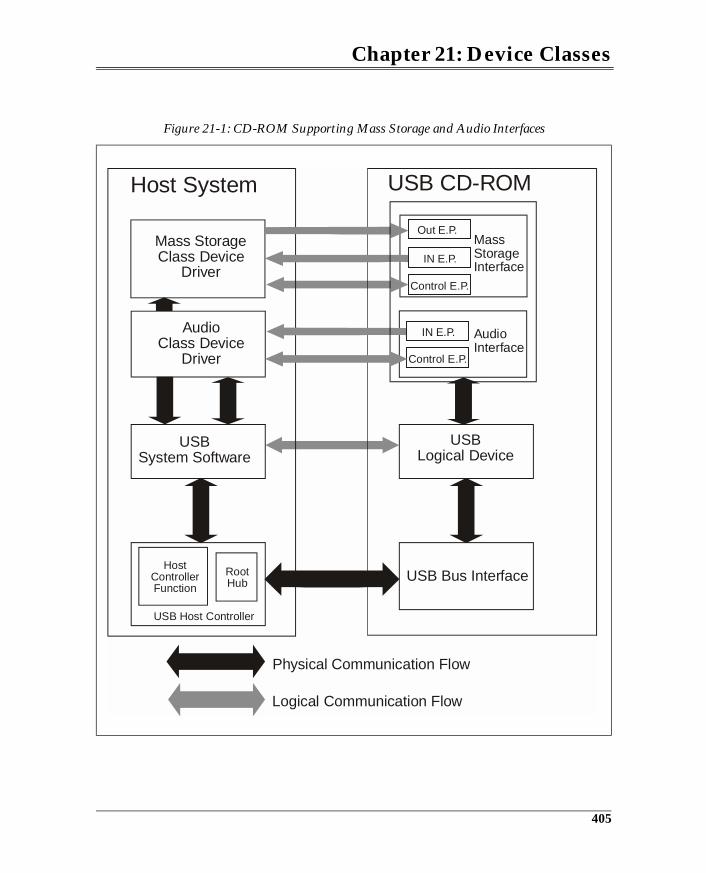
Chapter 21: Device Classes
Figure 21-1: CD-ROM Supporting Mass Storage and Audio Interfaces
Mass StorageClass Device
Driver
Host System USB CD-ROM
MassStorageInterface
AudioInterface
USBLogical Device
USB System Software
USB Bus Interface
Logical Communication Flow
Physical Communication Flow
RootHub
HostControllerFunction
USB Host Controller
Out E.P.
IN E.P.
IN E.P.
Control E.P.
Control E.P.
AudioClass Device
Driver
405
USB System Architecture
Device Classes
Device class documents can be found on the USB Implementers Forum web site(www.usb.org). The device classes that were approved at the time of this writ-ing include:
• Audio Class — Devices that are the source or sink of real-time audio infor-mation. This class is defined in four separate documents.- Audio Device Document 1.0- Audio Data Formats 1.0- Audio Terminal Types 1.0- USB MIDI (music instrument device interface) Devices 1.0
• Communications Device Class — Devices that attach to a telephone line(not local area networks). This class is defined in two documents:- Class Definitions for Communication Devices 1.1- Communications Device Class 1.0
• Content Security — This class defines transport mechanisms, descriptors,and USB requests to support a method for protecting the distribution ofdigital content via USB. The digital content being protected is usually copy-righted information. This class is defined in three documents:- Device Class Definition for Content Security Devices 1.0- Content Security Method 1 - Basic Authentication Protocol 1.0- Content Security Method 2 - USB Digital Transmission Content ProtectionImplementation 1.0
• Human Interface Device Class (HID) — Devices manipulated by end-users,and is defined in three documents:- Human Interface Devices 1.1- HID Usage Tables 1.1- HID Point of Sale Usage Tables 1.01
• Image Device Class — Devices that deal with still image capture.- Still Image Capture Device Definition 1.0 document.
• IrDA Class — This class defines an interface for infrared transceivers and isdefined by the:- IrDA Bridge Device Definition 1.0 Document.
• Mass Storage Device Class — Devices used to store large amounts of infor-mation (for example, floppy drives, hard drives, and tape drives). This classis defined by four documents:- Mass Storage Overview 1.1- Mass Storage Bulk Only 1.0- Mass Storage Control/Bulk/Interrupt (CBI) Specification 1.0- Mass Storage UFI Command Specification 1.0
406
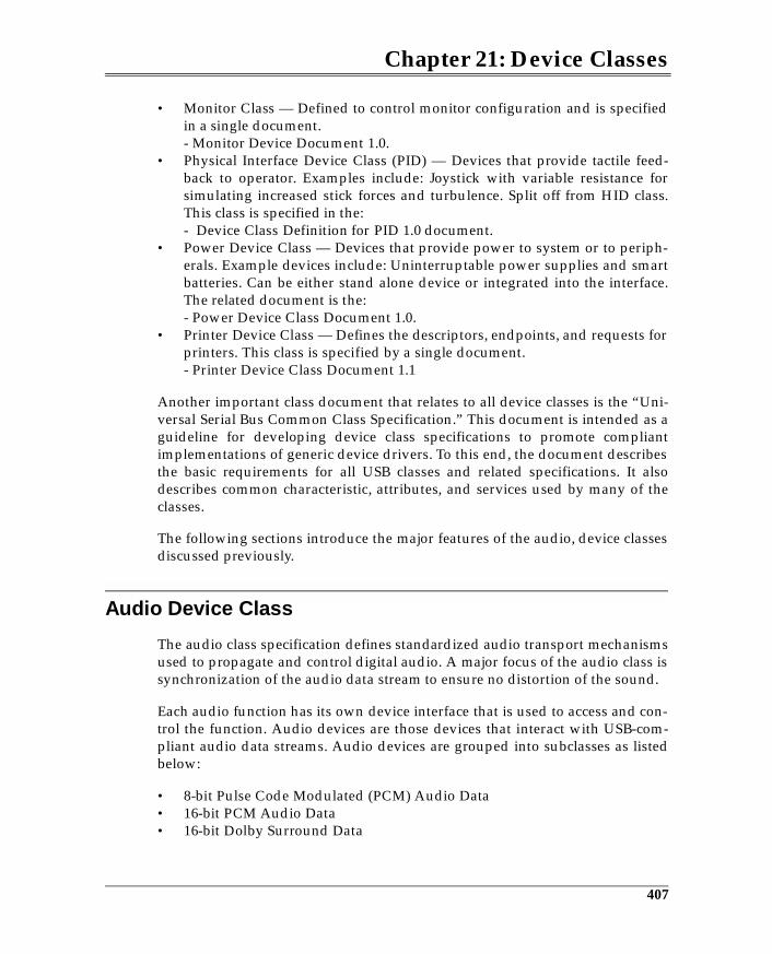
Chapter 21: Device Classes
• Monitor Class — Defined to control monitor configuration and is specifiedin a single document.- Monitor Device Document 1.0.
• Physical Interface Device Class (PID) — Devices that provide tactile feed-back to operator. Examples include: Joystick with variable resistance forsimulating increased stick forces and turbulence. Split off from HID class.This class is specified in the:- Device Class Definition for PID 1.0 document.
• Power Device Class — Devices that provide power to system or to periph-erals. Example devices include: Uninterruptable power supplies and smartbatteries. Can be either stand alone device or integrated into the interface.The related document is the:- Power Device Class Document 1.0.
• Printer Device Class — Defines the descriptors, endpoints, and requests forprinters. This class is specified by a single document.- Printer Device Class Document 1.1
Another important class document that relates to all device classes is the “Uni-versal Serial Bus Common Class Specification.” This document is intended as aguideline for developing device class specifications to promote compliantimplementations of generic device drivers. To this end, the document describesthe basic requirements for all USB classes and related specifications. It alsodescribes common characteristic, attributes, and services used by many of theclasses.
The following sections introduce the major features of the audio, device classesdiscussed previously.
Audio Device Class
The audio class specification defines standardized audio transport mechanismsused to propagate and control digital audio. A major focus of the audio class issynchronization of the audio data stream to ensure no distortion of the sound.
Each audio function has its own device interface that is used to access and con-trol the function. Audio devices are those devices that interact with USB-com-pliant audio data streams. Audio devices are grouped into subclasses as listedbelow:
• 8-bit Pulse Code Modulated (PCM) Audio Data • 16-bit PCM Audio Data• 16-bit Dolby Surround Data
407
22 Overview of USB Host Software
The Previous ChapterThe previous chapter introduced the concept of device classes and discussedtheir role within the USB. The chapter introduced the class types and provided amore detailed summary of the audio, mass storage, monitor, and communica-tions classes. These classes were discussed to provide the reader with a sense ofthe information defined for each class and the USB mechanisms that they use. Adetailed discussion of device classes requires in-depth knowledge in the associ-ated field such as telephony and audio, and is outside the scope of this book.
This ChapterHost software consists of three types of components: the USB Device Drivers,the USB Driver, and the host controller driver. This chapter discusses the role ofeach of these layers and describes the requirements of their programming inter-face.
USB Software
Host software provides the interface between USB device drivers (or client driv-ers) and the devices that they must communicate with. USB device drivers areunaware of the USB implementation. That is, they have no knowledge of thecharacteristics, capabilities, or limitations of the USB nor of the USB device.Consequently, USB host software must accept transfer requests made by USBdevice drivers and perform the requested transfers based on the requirementsof the USB. The following general capabilities are supported by a USB system.
• USB Interface Control• Configuration Services• Bus and Device Management• Power Control
421
USB System Architecture
• Device Data Access• Event Notification• Collection of Status and Activity Statistics• Error Detection and Handling
USB software is based on the device framework established by the USB specifi-cation. This framework describes the logical view that each software elementhas of the USB devices. The relationships between the USB software layers andtheir view of USB devices are reviewed below. Refer to Figure 22-1 on page 423.
Function Layer
Transactions performed over the USB are initiated by USB device drivers (clientdrivers). During configuration, the hub client accesses the bus, and whenaccessing other USB devices, the client drivers may be class-specific or vendor-specific. No matter which USB client driver wishes to access a given USBdevice, it must use host software to request its I/O transfer be performed overUSB (via an I/O request packet, or IRP). These clients only have knowledge ofthe device interface (consisting of a collection of endpoints) that they wish tomanipulate. Therefore a USB client driver’s visibility to USB is limited to:
• the interface within their device• class-specific descriptors that have been pre-defined to help them deter-
mine specific characteristics of their interface• the mechanisms provided by host software to access and control their func-
tion
Device Layer
Client initiated transfers must be performed according to the characteristics ofthe USB and the capabilities of the target USB device. USB host software existsto support USB clients by providing services that they can use to initiate trans-fers and control their devices.
Host software also ensures that the bus can support all devices attached to theUSB. The host software views each device through its standard device descrip-tors. These descriptors provide the necessary information to determine whichdriver will use this device and how much of the bus bandwidth is required.With this knowledge, host software can establish the communications pipesthat the clients will later use when they access their interface.
422
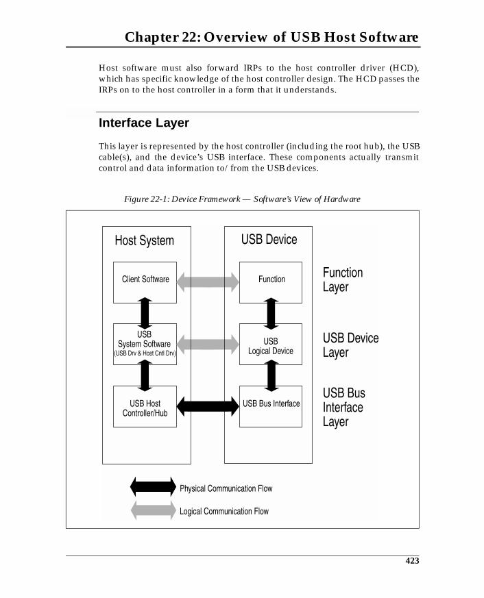
Chapter 22: Overview of USB Host Software
Host software must also forward IRPs to the host controller driver (HCD),which has specific knowledge of the host controller design. The HCD passes theIRPs on to the host controller in a form that it understands.
Interface Layer
This layer is represented by the host controller (including the root hub), the USBcable(s), and the device’s USB interface. These components actually transmitcontrol and data information to/from the USB devices.
Figure 22-1: Device Framework — Software’s View of Hardware
423
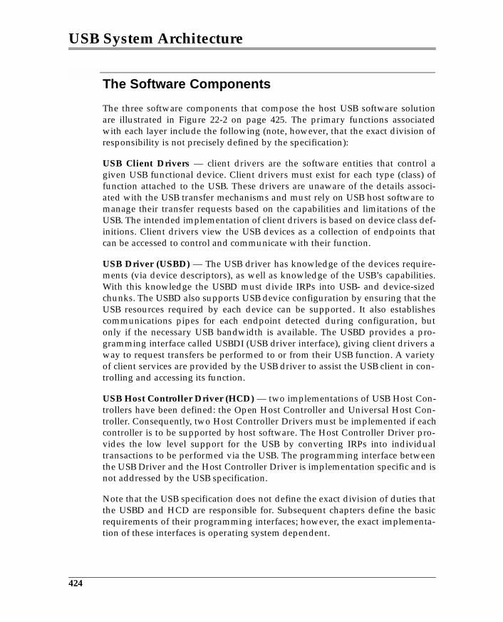
USB System Architecture
The Software Components
The three software components that compose the host USB software solutionare illustrated in Figure 22-2 on page 425. The primary functions associatedwith each layer include the following (note, however, that the exact division ofresponsibility is not precisely defined by the specification):
USB Client Drivers — client drivers are the software entities that control agiven USB functional device. Client drivers must exist for each type (class) offunction attached to the USB. These drivers are unaware of the details associ-ated with the USB transfer mechanisms and must rely on USB host software tomanage their transfer requests based on the capabilities and limitations of theUSB. The intended implementation of client drivers is based on device class def-initions. Client drivers view the USB devices as a collection of endpoints thatcan be accessed to control and communicate with their function.
USB Driver (USBD) — The USB driver has knowledge of the devices require-ments (via device descriptors), as well as knowledge of the USB’s capabilities.With this knowledge the USBD must divide IRPs into USB- and device-sizedchunks. The USBD also supports USB device configuration by ensuring that theUSB resources required by each device can be supported. It also establishescommunications pipes for each endpoint detected during configuration, butonly if the necessary USB bandwidth is available. The USBD provides a pro-gramming interface called USBDI (USB driver interface), giving client drivers away to request transfers be performed to or from their USB function. A varietyof client services are provided by the USB driver to assist the USB client in con-trolling and accessing its function.
USB Host Controller Driver (HCD) — two implementations of USB Host Con-trollers have been defined: the Open Host Controller and Universal Host Con-troller. Consequently, two Host Controller Drivers must be implemented if eachcontroller is to be supported by host software. The Host Controller Driver pro-vides the low level support for the USB by converting IRPs into individualtransactions to be performed via the USB. The programming interface betweenthe USB Driver and the Host Controller Driver is implementation specific and isnot addressed by the USB specification.
Note that the USB specification does not define the exact division of duties thatthe USBD and HCD are responsible for. Subsequent chapters define the basicrequirements of their programming interfaces; however, the exact implementa-tion of these interfaces is operating system dependent.
424
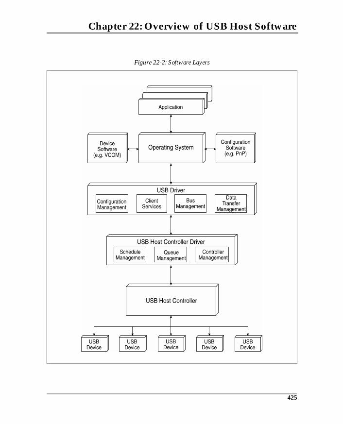
Chapter 22: Overview of USB Host Software
Figure 22-2: Software Layers
425
Appendix A:Standard DeviceRequestsOverview
All USB devices must respond to a variety of requests called “standard”requests. These requests are used for configuring a device, for controlling thestate of its USB interface, and with other miscellaneous features. Devicerequests are issued by the host using the control transfer mechanism. Prior toconfiguration, a device responds to its default address of zero. This permits con-figuration software to request the contents of any device’s descriptors (fromendpoint zero) using device address zero during configuration.
Additionally, devices may also support class-specific requests. Except for hubdevices, these class requests are defined by the device-class specifications andare not included within the main portion of the specification. Similarly, a devicemay support vendor-specific requests that pertain to a given vendor’s imple-mentation.
Control transfers, used to transmit device requests, consist minimally of a setupstage and a status stage, but may also include a data stage, depending on thetype of request being performed. The setup stage consists of setup transactionsas illustrated in Figure A-1. The eight byte data payload of a setup transactiondefines the type of request being issued by the host. This appendix discussesonly the standard device requests. Refer to the particular device class chapterfor information related to class-specific requests.
435
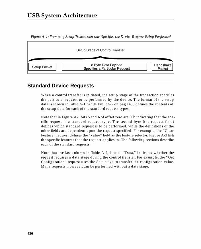
USB System Architecture
Standard Device Requests
When a control transfer is initiated, the setup stage of the transaction specifiesthe particular request to be performed by the device. The format of the setupdata is shown in Table A-1, while Tabl eA-2 on pag e438 defines the contents ofthe setup data for each of the standard request types.
Note that in Figure A-1 bits 5 and 6 of offset zero are 00b indicating that the spe-cific request is a standard request type. The second byte (the request field)defines which standard request is to be performed, while the definitions of theother fields are dependent upon the request specified. For example, the “ClearFeature” request defines the “value” field as the feature selector. Figure A-3 liststhe specific features that the request applies to. The following sections describeeach of the standard requests.
Note that the last column in Table A-2, labeled “Data,” indicates whether therequest requires a data stage during the control transfer. For example, the “GetConfiguration” request uses the data stage to transfer the configuration value.Many requests, however, can be performed without a data stage.
Figure A-1: Format of Setup Transaction that Specifies the Device Request Being Performed
436
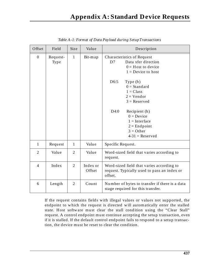
Appendix A: Standard Device Requests
If the request contains fields with illegal values or values not supported, theendpoint to which the request is directed will automatically enter the stalledstate. Host software must clear the stall condition using the “Clear Stall”request. A control endpoint must continue accepting the setup transaction, evenif it is stalled. If the default control endpoint fails to respond to a setup transac-tion, the device must be reset to clear the condition.
Table A-1: Format of Data Payload during Setup Transactions
Offset Field Size Value Description
0 Request-Type
1 Bit-map Characteristics of Request D7 Data xfer direction 0 = Host to device 1 = Device to host
D6:5 Type (h) 0 = Standard 1 = Class 2 = Vendor 3 = Reserved
D4:0 Recipient (h) 0 = Device 1 = Interface 2 = Endpoint 3 = Other 4-31 = Reserved
1 Request 1 Value Specific Request.
2 Value 2 Value Word-sized field that varies according to request.
4 Index 2 Index or Offset
Word-sized field that varies according to request. Typically used to pass an index or offset.
6 Length 2 Count Number of bytes to transfer if there is a data stage required for this transfer.
437
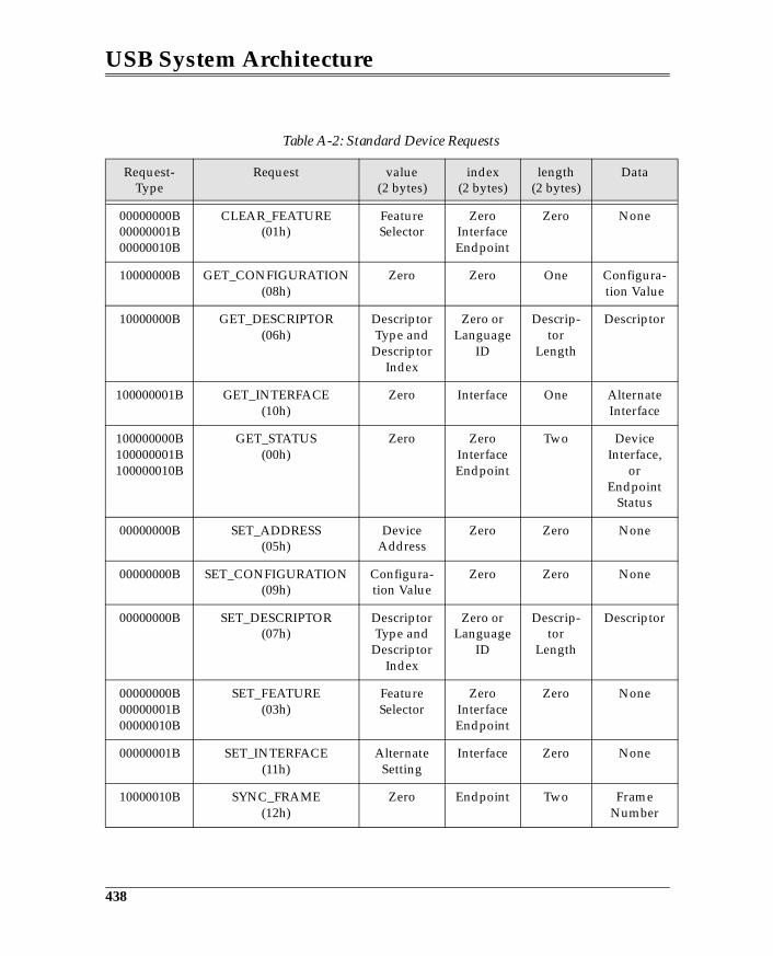
USB System Architecture
Table A-2: Standard Device Requests
Request-Type
Request value(2 bytes)
index(2 bytes)
length(2 bytes)
Data
00000000B00000001B00000010B
CLEAR_FEATURE(01h)
Feature Selector
ZeroInterfaceEndpoint
Zero None
10000000B GET_CONFIGURATION(08h)
Zero Zero One Configura-tion Value
10000000B GET_DESCRIPTOR(06h)
Descriptor Type and
Descriptor Index
Zero or Language
ID
Descrip-tor
Length
Descriptor
100000001B GET_INTERFACE(10h)
Zero Interface One Alternate Interface
100000000B100000001B100000010B
GET_STATUS(00h)
Zero ZeroInterfaceEndpoint
Two DeviceInterface,
orEndpoint
Status
00000000B SET_ADDRESS(05h)
DeviceAddress
Zero Zero None
00000000B SET_CONFIGURATION(09h)
Configura-tion Value
Zero Zero None
00000000B SET_DESCRIPTOR(07h)
DescriptorType and
DescriptorIndex
Zero or Language
ID
Descrip-tor
Length
Descriptor
00000000B00000001B00000010B
SET_FEATURE(03h)
FeatureSelector
ZeroInterfaceEndpoint
Zero None
00000001B SET_INTERFACE(11h)
AlternateSetting
Interface Zero None
10000010B SYNC_FRAME(12h)
Zero Endpoint Two Frame Number
438
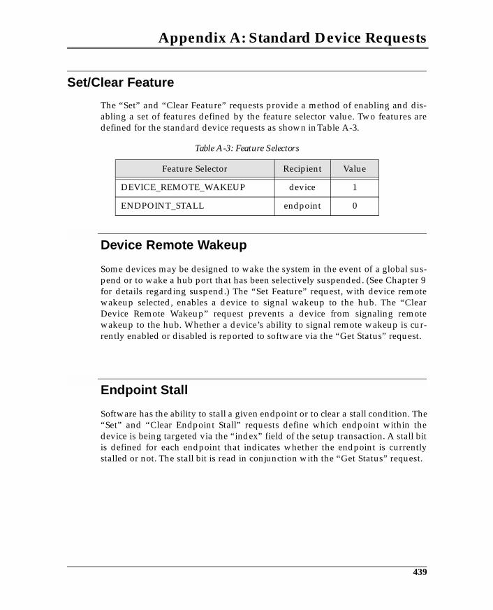
Appendix A: Standard Device Requests
Set/Clear Feature
The “Set” and “Clear Feature” requests provide a method of enabling and dis-abling a set of features defined by the feature selector value. Two features aredefined for the standard device requests as shown in Table A-3.
Device Remote Wakeup
Some devices may be designed to wake the system in the event of a global sus-pend or to wake a hub port that has been selectively suspended. (See Chapter 9for details regarding suspend.) The “Set Feature” request, with device remotewakeup selected, enables a device to signal wakeup to the hub. The “ClearDevice Remote Wakeup” request prevents a device from signaling remotewakeup to the hub. Whether a device’s ability to signal remote wakeup is cur-rently enabled or disabled is reported to software via the “Get Status” request.
Endpoint Stall
Software has the ability to stall a given endpoint or to clear a stall condition. The“Set” and “Clear Endpoint Stall” requests define which endpoint within thedevice is being targeted via the “index” field of the setup transaction. A stall bitis defined for each endpoint that indicates whether the endpoint is currentlystalled or not. The stall bit is read in conjunction with the “Get Status” request.
Table A-3: Feature Selectors
Feature Selector Recipient Value
DEVICE_REMOTE_WAKEUP device 1
ENDPOINT_STALL endpoint 0
439
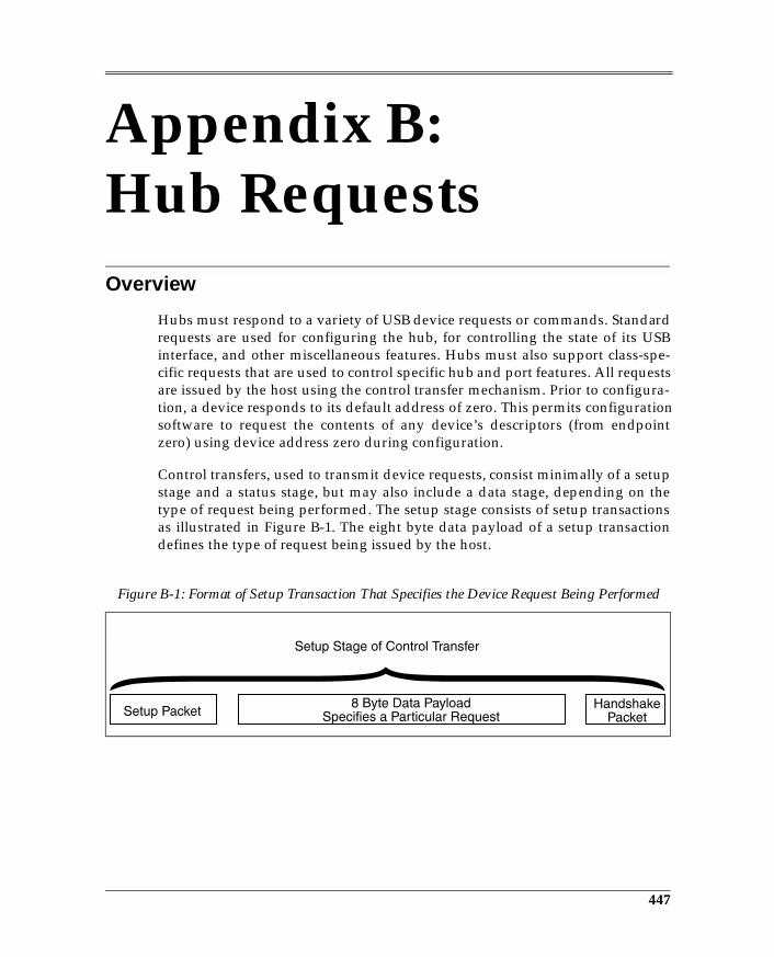
Appendix B: Hub RequestsOverview
Hubs must respond to a variety of USB device requests or commands. Standardrequests are used for configuring the hub, for controlling the state of its USBinterface, and other miscellaneous features. Hubs must also support class-spe-cific requests that are used to control specific hub and port features. All requestsare issued by the host using the control transfer mechanism. Prior to configura-tion, a device responds to its default address of zero. This permits configurationsoftware to request the contents of any device’s descriptors (from endpointzero) using device address zero during configuration.
Control transfers, used to transmit device requests, consist minimally of a setupstage and a status stage, but may also include a data stage, depending on thetype of request being performed. The setup stage consists of setup transactionsas illustrated in Figure B-1. The eight byte data payload of a setup transactiondefines the type of request being issued by the host.
Figure B-1: Format of Setup Transaction That Specifies the Device Request Being Performed
447
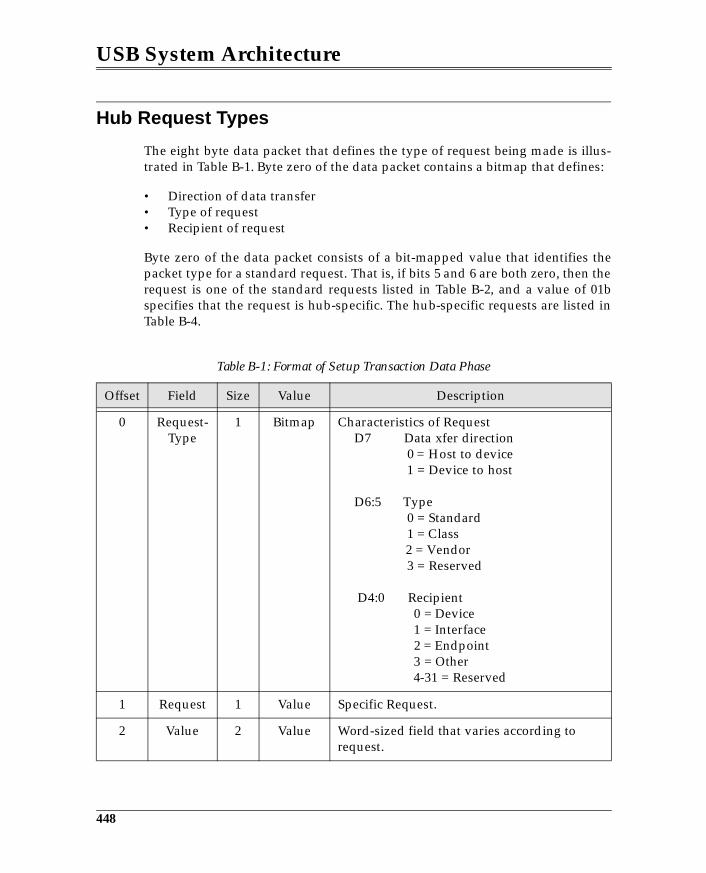
USB System Architecture
Hub Request Types
The eight byte data packet that defines the type of request being made is illus-trated in Table B-1. Byte zero of the data packet contains a bitmap that defines:
• Direction of data transfer• Type of request• Recipient of request
Byte zero of the data packet consists of a bit-mapped value that identifies thepacket type for a standard request. That is, if bits 5 and 6 are both zero, then therequest is one of the standard requests listed in Table B-2, and a value of 01bspecifies that the request is hub-specific. The hub-specific requests are listed inTable B-4.
Table B-1: Format of Setup Transaction Data Phase
Offset Field Size Value Description
0 Request-Type
1 Bitmap Characteristics of Request D7 Data xfer direction 0 = Host to device 1 = Device to host
D6:5 Type 0 = Standard 1 = Class 2 = Vendor 3 = Reserved
D4:0 Recipient 0 = Device 1 = Interface 2 = Endpoint 3 = Other 4-31 = Reserved
1 Request 1 Value Specific Request.
2 Value 2 Value Word-sized field that varies according to request.
448
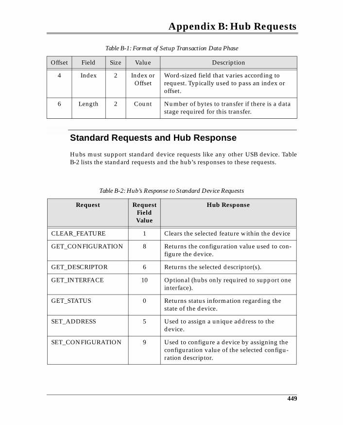
Appendix B: Hub Requests
Standard Requests and Hub Response
Hubs must support standard device requests like any other USB device. TableB-2 lists the standard requests and the hub’s responses to these requests.
4 Index 2 Index or Offset
Word-sized field that varies according to request. Typically used to pass an index or offset.
6 Length 2 Count Number of bytes to transfer if there is a data stage required for this transfer.
Table B-2: Hub’s Response to Standard Device Requests
Request Request Field Value
Hub Response
CLEAR_FEATURE 1 Clears the selected feature within the device
GET_CONFIGURATION 8 Returns the configuration value used to con-figure the device.
GET_DESCRIPTOR 6 Returns the selected descriptor(s).
GET_INTERFACE 10 Optional (hubs only required to support one interface).
GET_STATUS 0 Returns status information regarding the state of the device.
SET_ADDRESS 5 Used to assign a unique address to the device.
SET_CONFIGURATION 9 Used to configure a device by assigning the configuration value of the selected configu-ration descriptor.
Table B-1: Format of Setup Transaction Data Phase
Offset Field Size Value Description
449
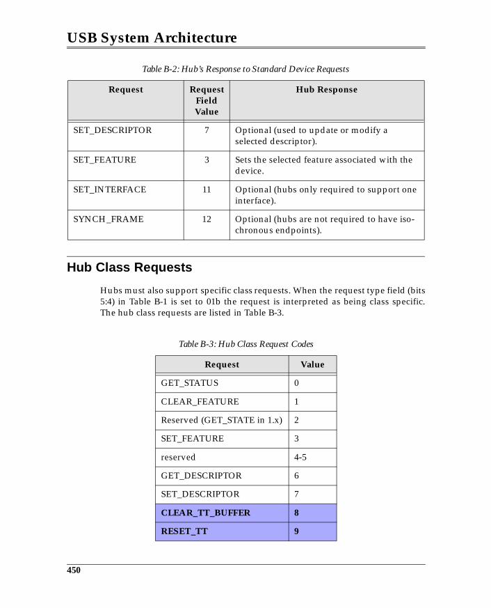
USB System Architecture
Hub Class Requests
Hubs must also support specific class requests. When the request type field (bits5:4) in Table B-1 is set to 01b the request is interpreted as being class specific.The hub class requests are listed in Table B-3.
SET_DESCRIPTOR 7 Optional (used to update or modify a selected descriptor).
SET_FEATURE 3 Sets the selected feature associated with the device.
SET_INTERFACE 11 Optional (hubs only required to support one interface).
SYNCH_FRAME 12 Optional (hubs are not required to have iso-chronous endpoints).
Table B-3: Hub Class Request Codes
Request Value
GET_STATUS 0
CLEAR_FEATURE 1
Reserved (GET_STATE in 1.x) 2
SET_FEATURE 3
reserved 4-5
GET_DESCRIPTOR 6
SET_DESCRIPTOR 7
CLEAR_TT_BUFFER 8
RESET_TT 9
Table B-2: Hub’s Response to Standard Device Requests
Request Request Field Value
Hub Response
450
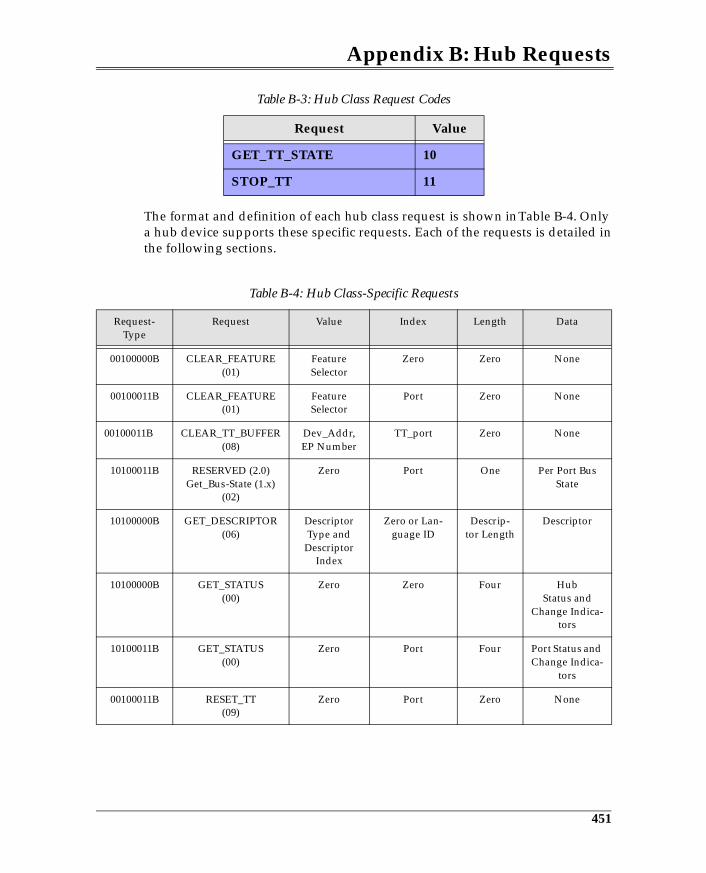
Appendix B: Hub Requests
The format and definition of each hub class request is shown in Table B-4. Onlya hub device supports these specific requests. Each of the requests is detailed inthe following sections.
GET_TT_STATE 10
STOP_TT 11
Table B-4: Hub Class-Specific Requests
Request-Type
Request Value Index Length Data
00100000B CLEAR_FEATURE(01)
FeatureSelector
Zero Zero None
00100011B CLEAR_FEATURE(01)
FeatureSelector
Port Zero None
00100011B CLEAR_TT_BUFFER(08)
Dev_Addr,EP Number
TT_port Zero None
10100011B RESERVED (2.0)Get_Bus-State (1.x)
(02)
Zero Port One Per Port Bus State
10100000B GET_DESCRIPTOR(06)
Descriptor Type and
Descriptor Index
Zero or Lan-guage ID
Descrip-tor Length
Descriptor
10100000B GET_STATUS(00)
Zero Zero Four HubStatus and
Change Indica-tors
10100011B GET_STATUS(00)
Zero Port Four Port Status and Change Indica-
tors
00100011B RESET_TT(09)
Zero Port Zero None
Table B-3: Hub Class Request Codes
Request Value
451
Appendix C:Universal Host Controller
Overview
The Universal Host Controller (UHC) and the Universal Host Controller Driver(UHCD) are responsible for scheduling and executing IRPs forwarded from theUSB driver. The UHC also integrates the root hub function that is compliantwith the USB hub definition. The root hub integrated into the UHC has two USBports. The following sections describe the mechanism used by the UHC toschedule and generate transactions via the USB.
The UHC is integrated into the Intel PIIX3 PCI ISA Expansion Bus Bridge andlater chips. It is implemented as a PCI master and is capable of performingtransactions to and from memory to fetch and update data structures built bythe UHCD.
Universal Host Controller Transaction Scheduling
The sequence of transactions scheduled and performed during each 1ms frameis illustrated in Figure C-1. Note that the periodic transfers are scheduled first(isochronous and interrupt), followed by the control and bulk transfers. Theperiodic transfers can take up to 90% of the bus bandwidth and control transfersare guaranteed at least 10% of the bandwidth.
The UHCD schedules transactions by building a series of transfer descriptorsthat are linked to form the collection of transactions that are to be performedduring a given frame. This is known as the frame list and is located in systemmemory.
465
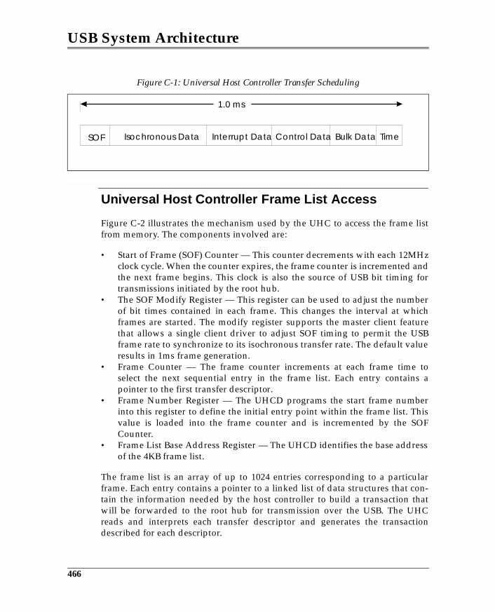
USB System Architecture
Universal Host Controller Frame List Access
Figure C-2 illustrates the mechanism used by the UHC to access the frame listfrom memory. The components involved are:
• Start of Frame (SOF) Counter — This counter decrements with each 12MHzclock cycle. When the counter expires, the frame counter is incremented andthe next frame begins. This clock is also the source of USB bit timing fortransmissions initiated by the root hub.
• The SOF Modify Register — This register can be used to adjust the numberof bit times contained in each frame. This changes the interval at whichframes are started. The modify register supports the master client featurethat allows a single client driver to adjust SOF timing to permit the USBframe rate to synchronize to its isochronous transfer rate. The default valueresults in 1ms frame generation.
• Frame Counter — The frame counter increments at each frame time toselect the next sequential entry in the frame list. Each entry contains apointer to the first transfer descriptor.
• Frame Number Register — The UHCD programs the start frame numberinto this register to define the initial entry point within the frame list. Thisvalue is loaded into the frame counter and is incremented by the SOFCounter.
• Frame List Base Address Register — The UHCD identifies the base addressof the 4KB frame list.
The frame list is an array of up to 1024 entries corresponding to a particularframe. Each entry contains a pointer to a linked list of data structures that con-tain the information needed by the host controller to build a transaction thatwill be forwarded to the root hub for transmission over the USB. The UHCreads and interprets each transfer descriptor and generates the transactiondescribed for each descriptor.
Figure C-1: Universal Host Controller Transfer Scheduling
SOF TimeBulk DataControl DataInterrupt DataIsochronous Data
1.0 ms
466
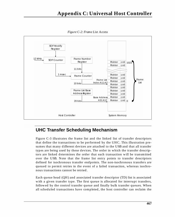
Appendix C: Universal Host Controller
UHC Transfer Scheduling Mechanism
Figure C-3 illustrates the frame list and the linked list of transfer descriptorsthat define the transactions to be performed by the UHC. This illustration pre-sumes that many different devices are attached to the USB and that all transfertypes are being used by these devices. The order in which the transfer descrip-tors are linked determines the order that each transaction will be transmittedover the USB. Note that the frame list entry points to transfer descriptorsdefined for isochronous transfer endpoints. The non-isochronous transfers arequeued to permit retries in the event of a failed transaction, whereas isochro-nous transactions cannot be retried.
Each queue head (QH) and associated transfer descriptor (TD) list is associatedwith a given transfer type. The first queue is allocated for interrupt transfers,followed by the control transfer queue and finally bulk transfer queues. Whenall scheduled transactions have completed, the host controller can reclaim the
Figure C-2: Frame List Access
Frame List BaseAddress Register
SOF ModifyRegister
SOF Counter Frame NumberRegister
Frame Counter1 msec
cntlcntl
cntlcntlcntlcntlcntlcntlcntlcntlcntlPointer
PointerPointerPointerPointerPointerPointerPointerPointer
PointerPointer
Frame ListIndex A11:A2
Base AddressA31:A12
System MemoryHost Controller
12 MHz
11 bits
10 bits
20 bits
FrameList
1023
0
467
USB System Architecture
remaining bus bandwidth by performing additional control and bulk transfers.
Bus Bandwidth Reclamation
Bus bandwidth reclamation can be implemented such that when all scheduledtransactions have completed, the UHC can use the remaining frame time to per-form additional transactions. This requires that the last QH in the list pointsback to the beginning of the control and bulk queues. Each QH also has a termi-nation bit that, when set, terminates the transfer sequence, and no reclamationoccurs.
The UHC tracks frame timing to monitor the amount of frame time left forscheduling additional transactions. A sample point (called PreSOF point) per-mits the UHC to determine if there is sufficient time to start the next transactionbefore the end of packet. The PreSOF point can be selected for 32- or 64-bytepackets under software control. If the packet cannot complete in the remainingtime, it is not performed.
Transfer Descriptors
This section defines the contents of the transfer descriptors and the queueheads. Figure C-4 illustrates the contents of a transfer descriptor. In general,transfer descriptors contain the information needed by the UHC to generate atransaction and report status, including:
• Transfer Type (isochronous and other)• Type of Token Packet (IN, OUT, SETUP)• Direction of Transfer• Size of Data Packet• Data Toggle Bit• Memory Buffer Location• Completion Status
The transfer descriptor consists of four double words (DW0 - DW3). Each DWwithin the transfer descriptor is defined in tables Table C-1 - Table C-4.
468
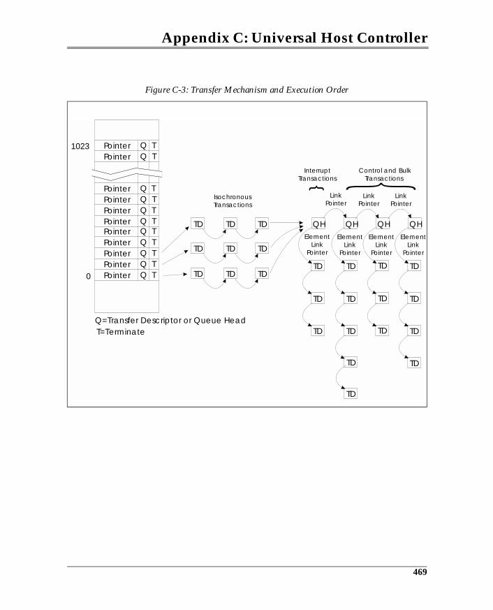
Appendix C: Universal Host Controller
Figure C-3: Transfer Mechanism and Execution Order
TQTQ
TQTQTQTQTQTQTQTQT
T=Terminate
TD
TD TD
TD
TD
TD TD
TD
TD QH
TDTD TD
TD
TD TD
TD
TD QH
LinkPointer
InterruptTransactions
Control and BulkTransactions
IsochronousTransactions
ElementLink
Pointer
ElementLink
Pointer
ElementLink
Pointer
ElementLink
Pointer
LinkPointer
LinkPointer
TD
TD TD TD TD
TD
TD QH QH
Q
Q=Transfer Descriptor or Queue Head
PointerPointerPointerPointerPointerPointerPointerPointerPointer
PointerPointer1023
0
469
Appendix D:Open HostControllerOverview
The Open Host Controller (OHC) and the Open Host Controller Driver(OHCD) are responsible for scheduling and executing IRPs forwarded from theUSB driver. The OHC also integrates the root hub function that is compliantwith the USB hub definition. The root hub integrated into the OHC has twoUSB ports. The following sections describe the mechanisms used by the OHCand OHCD to schedule and generate transactions via the USB.
Open Host Controller Transfer Scheduling
Figure D-1 on page 478 illustrates the sequence of transfers performed by theOpen Host Controller. Note that a reservation can be made at the beginning ofthe frame (for non-periodic transfers) to support the 10% bandwidth guaranteefor control transfers and to ensure that some non-periodic transfers (control andbulk) get performed during each frame. Next, the periodic transfers (interruptand isochronous) are performed and can take up to 90% of the bus bandwidth;if time remains, then additional non-periodic transfers can be scheduled.
The OHCD schedules transactions by building a series of transfer descriptorsthat are linked to form the collection of transactions to be performed during agiven frame. This is known as the frame list and is located in system memory.
477
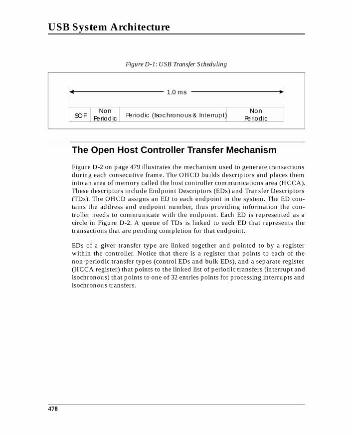
USB System Architecture
The Open Host Controller Transfer Mechanism
Figure D-2 on page 479 illustrates the mechanism used to generate transactionsduring each consecutive frame. The OHCD builds descriptors and places theminto an area of memory called the host controller communications area (HCCA).These descriptors include Endpoint Descriptors (EDs) and Transfer Descriptors(TDs). The OHCD assigns an ED to each endpoint in the system. The ED con-tains the address and endpoint number, thus providing information the con-troller needs to communicate with the endpoint. Each ED is represented as acircle in Figure D-2. A queue of TDs is linked to each ED that represents thetransactions that are pending completion for that endpoint.
EDs of a giver transfer type are linked together and pointed to by a registerwithin the controller. Notice that there is a register that points to each of thenon-periodic transfer types (control EDs and bulk EDs), and a separate register(HCCA register) that points to the linked list of periodic transfers (interrupt andisochronous) that points to one of 32 entries points for processing interrupts andisochronous transfers.
Figure D-1: USB Transfer Scheduling
SOFNon
PeriodicNon
PeriodicPeriodic (Isochronous & Interrupt)
1.0 ms
478
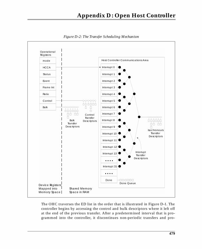
Appendix D: Open Host Controller
The OHC traverses the ED list in the order that is illustrated in Figure D-1. Thecontroller begins by accessing the control and bulk descriptors where it left offat the end of the previous transfer. After a predetermined interval that is pro-grammed into the controller, it discontinues non-periodic transfers and pro-
Figure D-2: The Transfer Scheduling Mechanism
mode Host Controller Communications Area
OperationalRegisters
Interrupt 0
Interrupt 1
Interrupt 2
Interrupt 3
Interrupt 5
IsochronoursTransfer
Descriptors
InterruptTransfer
Descriptors
ControlTransfer
DescriptorsBulkTransfer
Descriptors
Interrupt 4
Interrupt 6
Interrupt 7
Interrupt 9
Interrupt 11
....
....
Interrupt 13
Interrupt 12
Interrupt 31
DoneDone Queue
Interrupt 10
Interrupt 8
HCCA
Status
Event
Frame Int
Control
Bulk
Ratio
Device RegistersMapped intoMemory Space
Shared MemorySpace in RAM
479
USB System Architecture
ceeds to the periodic transfers via the HCCA register. Note that interrupts arescheduled differently from the other transfer types. The HCCA register incre-ments at the end of each frame to point at the next linked list of interrupt TDs,which are scheduled for completion during the current frame. The end of theinterrupt list always links to the beginning of the isochronous EDs. Once theisochronous transfers have completed, the controller is free to continue process-ing control and bulk transfers where it left off, if sufficient time remains withinthe current frame.
The OHC links transfer descriptors to the “Done” queue after it has completedsuccessfully or if an error has occurred when performing the TD. The OHCDcan then check the done queue for completion status information.
The ED and TD List Structure
All transfers are scheduled using the standard TD list structure as illustrated inFigure D-3. The head pointer is the OHC register for control and bulk transfers.A different interrupt head pointer is selected for each frame as the HCCA regis-ter value increments. The interrupt head pointer is located in the HCCA mem-ory area. Isochronous EDs simply link from the last interrupt ED in the currentinterrupt list. TDs are enqueued to each ED as IRPs are requested by USB devicedrivers. An endpoint that is currently idle will not have any TDs enqueued.
Interrupt and Isochronous Transfer Processing
Processing the interrupt and isochronous ED list begins with the interrupt headpointer for the current frame. The list is traversed sequentially, until one trans-action associated with the first TD has been performed for each endpoint in thelist.
Control and Bulk Transfer Processing
At the beginning of a frame the control and bulk queues are processed until the“remaining” field of the HcFmRemaining register is less than or equal to the“start” field of the HcPeriodicStart register. More control transfers are per-formed than bulk transfers based on a ratio of control to bulk transfers specifiedwithin the “ControlBulkServiceRatio” field of the HcControl register. The con-troller performs these transfers based on a round robin sequence tied to theratio (e.g., three control transfer followed by one bulk transfer). If sufficient timeremains within the frame after completing the periodic transfers, the controllerreturns to the control and bulk lists, and continues processing where it left off.
480
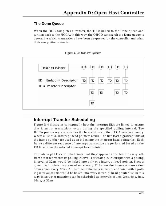
Appendix D: Open Host Controller
The Done Queue
When the OHC completes a transfer, the TD is linked to the Done queue andwritten back to the HCCA. In this way, the OHCD can search the Done queue todetermine which transactions have been de-queued by the controller and whattheir completion status is.
Interrupt Transfer SchedulingFigure D-4 illustrates conceptually how the interrupt EDs are linked to ensurethat interrupt transactions occur during the specified polling interval. TheHCCA pointer register specifies the base address of the HCCA area in memorywhere a list of 32 interrupt head pointers reside. The five least significant bits ofthe frame number are used as an index into the interrupt head pointer list. Eachframe a different sequence of interrupt transaction are performed based on theED links from the selected interrupt head pointer.
The interrupt EDs are linked such that they appear in the list for every nthframe that represents its polling interval. For example, interrupts with a pollinginterval of 32ms would be linked into only one interrupt head pointer. Since agiven head pointer is accessed once every 32 frames the interrupt transactionoccurs once every 32ms. At the other extreme, a interrupt endpoint with a poll-ing interval of 1ms would be linked into every interrupt head pointer list. In thisway, interrupt transactions can be scheduled at intervals of 1ms, 2ms, 4ms, 8ms,16ms, or 32ms.
Figure D-3: Transfer Queues
Header Pointer ED
ED = Endpoint Descriptor
TD = Transfer Descriptor
TD TD TD TD TD TD
TDTDTDTD
TD
ED ED ED ED ED
481
Index
Numerics1.x device compatibility 371.x devices in HS system 37, 38, 39, 4016-bit CRC 1702.0 host controller 40, 2165-bit CRC 150, 170
AACK 157, 160acknowledge packet, see ACK 153adaptive sink 130, 131adaptive source 131adaptive synchronization 128address assignment 345alternate interfaces 365alternate settings 364asynchronous sink 130, 131asynchronous source 130asynchronous synchronization 128attachment sequence 96attachment sequence, HS 221attachment timing, HS 221attachment timing, LS/FS 96Audio Class-Specific Descriptors 409Audio Class-Specific Requests 410
Bbabble 192babbling device recovery, HS 270babbling device recovery, LS 190babbling devices 189babbling devices after resume 208babbling devices, HS 268babbling devices, LS 189, 192bandwidth allocation 58, 345
bandwidth allocation, bulk trans-fers 137bandwidth allocation, control 137bandwidth allocation, control transfers 121bandwidth allocation, HS control transfers 243, 254bandwidth allocation, HS periodic transfers 243bandwidth allocation, LS/FS 121bandwidth allocation, periodic transfers 121bandwidth sharing 34bandwidth, HS 244bandwidth, HS interrupt 247bit stuff errors 168bit stuff time 428bit stuffing 112bit stuffing errors 170, 236bulk transfer bandwidth 36bulk transfer bandwidth, HS 255, 256bulk transfers 55, 118, 137bulk/control IN transaction se-quence 332bulk/control split transaction se-quence 328bulk/control transaction buffer 299bus bandwidth 34, 36, 426, 428bus bandwidth allocation 346bus bandwidth reclamation 429bus bandwidth sharing 34bus bandwidth, bulk 138bus bandwidth, HS 44bus bandwidth, interrupt 135
495
Index
bus bandwidth, isochronous 123bus idle 102bus idle, full speed 102bus idle, high speed 227bus idle, low speed 102bus powered hubs 49bus time-out, HS 266bus time-out, LS/FS 172, 173bus turn-around time 172bus-powered device 82bus-powered hub 80
Ccable cross-section, FS/HS 73cable cross-section, LS 72cable delay 173cable delay, FS 107cable length, FS & HS 73cable length, LS 72cable power 74cable propagation delay, FS & HS 73cable propagation delay, LS 72cables 71cables, FS & HS 73chirp J 222chirp K 221, 222chirp sequence 219, 221, 223class codes 358class-specific descriptor 61Clear Hub Feature request 398Clear Hub Local Power Change 456Clear Hub Local Power Feature re-quest 399Clear Hub Over-Current Change request 456
Clear Port Feature request 462Clear Stall request 437client driver 45client drivers 346client pipes 430client software during configura-tion 343command mechanisms 430, 431Common Class Specification 407Communication Device Class 410Communications Class-Specific Descriptors 412Communications Class-Specific Requests 412Communications Device Interfaces 411communications pipes 118, 119Complete Split 290complete split transaction 39complete-split buffer 299, 312complete-split packet format 314composite device 358compound device 80, 358configuration 53configuration descriptor 60configuration descriptors 60, 76, 77, 359, 361, 377configuration descriptors, hub 380configuration sequence 340configuration software 342configuration software elements 341configuration summary 348configuration value 346, 361, 381configuration, assigning configu-ration value 346
496
Index
configuration, client drivers load-ed 346connection event 96connector contacts 70connectors 69control transfer 136control transfer bandwidth 36control transfer bandwidth, HS 257control transfer bandwidth, LS/FS 121control transfer error recovery 193control transfer stages 137, 163control transfer, three stage 165control transfer, two stage 164control transfers 55, 118, 137, 163control transfers with errors 166CRC 146, 168, 169, 170CRC16 handling, interrupt split transfers 326CRC16 handling, isochronous split transfers 315, 319current budget 76current during configuration 80current limiting 78, 81current, per port 76Cyclic Redundancy Check (CRC) 144
Ddata endpoints 134data packet errors 171data packets 60, 143, 145, 152data stage 137, 163data toggle 152, 175, 253DATA0 175data0 packet 152DATA0 packets 152
DATA1 175data1 packet 152DATA1 packets 152DATA2 packet 253debounce interval 97default control endpoint 340default control pipe 342, 376default control port 376default device address 345default pipe 376, 430depth of topology 429descriptor 376descriptor types 441descriptors, accessing 354detecting device attachment 348device attachment 98device attachment, high speed 219, 221device attachment, low speed 100device attachment, LS/FS 94device class 366Device class specifications 24device configuration 340, 344, 426device connect 96, 99device connect, Full Speed 98device connect, high speed 219device descriptor 60, 355, 377device descriptors, hub 379device disconnect, HS 236device disconnect, LS/FS 101Device Framework 53, 60, 423device layer 422device qualifier descriptor 360device reset 345device states 371Differential 0 113
497
Index
Differential 1 113differential amplifier 109differential data 111differential driver 106differential envelope detector 227differential receivers, HS 227differential signaling 105differential signaling, high speed 224differential signaling, HS 227differential signaling, LS/FS 109disconnect envelope detector 237, 238Display Device Class 412Display Device Class Interface 413Display Device-Specific Descrip-tors 413DMA channel 54DMA channels 14, 18downstream (away from the host) 52drain wire 72, 73dribble bits 285
Eelasticity buffer 285, 286electrical specification 74end of frame (EOF) 190end of packet, high speed 236end of packet, see EOP 110, 147endpoint 55endpoint descriptor 61, 367, 368, 377, 428endpoint status 443endpoint zero 19, 340endpoints 19
Enhanced Host Controller (EHCI) 47Enhanced Host Controller Interface 216enumeration 339EOF1 190EOF2 190, 192, 463EOP 110, 114, 144, 147EOP, high speed 236EOP2 397Error checking mechanisms 167error recover, interrupts 135error recovery, bulk 139error recovery, isochronous 124errors, packet 171explicit feedback 134eye diagrams 227, 231eye diagrams, receiver 233eye diagrams, transmitter 232eye patterns 229
Ffairness 34false EOP 174false EOP, HS 267feed forwarding 128, 130feedback 128, 130, 131feedback data 131, 133feedback endpoints 134frame 33, 34, 46, 47, 57, 121frame list 30, 33frame timer 208full speed cable 73full/high-speed cable cross section 73full-speed cable length 73full-speed cables 71, 73
498
Index
full-speed devices 28, 53, 66full-speed drivers 106full-speed transactions 28full-speed transmission 71function configuration 427function layer 65
Gganged power switching 79, 387Get Bus State request 463Get Descriptor request 377Get Hub Descriptor request 387, 452Get Hub Status 456Get Hub Status request 398, 452, 453, 455, 456Get Port Status request 398, 399, 462Get Status request 442Get/Set Configuration request 440Get/Set Descriptor request 440Get/Set Interface request 441global suspend 195, 197, 204
Hhalf-duplex 105handshake packet 143handshake packet errors 172handshake packet formats 154handshake packets 60, 145, 153hardware and software elements 44HCD 423, 424high bandwidth isochronous 251high speed handler 311high/full-speed cable cross section 73high-bandwidth 249
high-bandwidth interrupt transac-tions 253, 254high-bandwidth isochronous 252high-bandwidth isochronous transactions 254high-bandwidth throughput 254high-bandwidth transactions 249, 250high-speed babbling device detec-tion 268high-speed bandwidth 42, 44, 243high-speed bulk transfers 255high-speed bus idle 227high-speed bus time-out 266high-speed cables 73high-speed control transfers 257high-speed device disconnect 236high-speed device features 214high-speed devices 41, 53, 66, 213, 214, 217high-speed devices in FS system 41high-speed devices, test mode 229high-speed differential receivers 227high-speed drivers 226High-Speed End Of Packet 286high-speed EOP 237high-speed handler 298, 299, 328high-speed hub repeater 284high-speed hubs 67, 218, 278high-speed interrupt bandwidth 247, 249high-speed interrupt transfers 247high-speed isochronous band-width 246high-speed packets 242
499
Index
high-speed port 215high-speed reset 239high-speed resume 273high-speed signaling 219high-speed suspend 239, 272high-speed transactions 42, 242, 280high-speed transfers 37, 243high-speed transmission 71host controller 47, 48Host Controller Drive 44host controller driver 59host frame timing 208host recovery time 428hot plug 20hub class descriptor 387hub class descriptor (2.0) 394hub class request 451hub class requests 450hub client 347hub controller 48, 50, 51hub delay, FS 173hub descriptor 377hub descriptors (2.0) 391hub functions 48hub low speed setup 428hub port states 399Hub port status information 352hub power 76hub repeater 52hub repeater functions, HS 284hub repeater state machine 191hub repeater state matching, HS 286hub repeater states 192hub repeater, HS 279
hub request 448hub requests 448hub resume state 208Hub Set /Clear Feature request 461hub state change 454hub status change endpoint 343Hub Status Endpoint Descriptor 386hub status fields 453hub suspend state 196hub types 50hubs 49, 66, 76hubs, FS 66hubs, HS 67, 278, 281, 283hub-specific requests, summary 451Human Interface Device Class 412hybrid powered device 89hybrid powered hub 87hybrid-powered 381
II/O request packet, see IRP 120I/O Request Packets 45idle state 104, 114idle, high speed 223impedance matching 224IN 157IN token 147IN token packet 149IN transaction errors 157IN transactions 156, 157initiating global suspend 197input sensitivity 109insufficient bus current 84interface descriptor 60, 364, 377interface descriptors, hubs 383
500
Index
interface layer 423interface number 364Interrupt IN split transaction se-quence 322interrupt OUT split transaction sequence 319interrupt transfer error recovery 193interrupt transfers 55, 118, 134interrupt transfers, HS 247IO Hub-based host controller 25IRP 45, 46, 57, 422, 429IRP, see I/O request packet 120IRQ 14, 15, 54isochronous data endpoints 134isochronous data packets, HS 244Isochronous IN split transaction sequence 316isochronous OUT split transaction sequence 313isochronous OUT transactions 162isochronous packet overhead, HS 245isochronous split transactions 291, 292isochronous transactions 34, 36, 125isochronous transactions, HS 44isochronous transfer 159isochronous transfer error recov-ery 193isochronous transfers 55, 118, 123isochronous transfers, HS 244
JJ state 104, 113
KK state 104, 114
Ll.x hubs 66legacy 14legacy connectors 17legacy I/O 14, 16legacy interrupts 15LOA 192, 208LOA error 189local power status 453loss of activity (LOA) 189low- and full-speed overview 28low speed cables 72low speed drivers 108low-/full-speed handler 299, 328low-power device 82low-speed cable 53, 71Low-speed cable length 72low-speed devices 28, 53, 66low-speed packets 145low-speed transactions 28, 154low-speed/full-speed handler 312
MMass Storage Device Class 414max. data packet size, bulk transfers 138max. data packet size, control transfers 137max. packet size, interrupt transfers 135max. packet size, isochronous transfers 123maximum packet size 385
501
Index
maximum packet size, HS bulk 255maximum packet size, HS interrupt 247maximum packet size, HS isochronous 244MaxPower field 76, 77MDATA packet 252mechanical specification 74message pipes 430microframe 46, 242, 251, 300microframes 243microframes generation 42microSOF packets 237, 238, 300multiple transaction translators 309
NNAK 158, 161No Acknowledge packet, see NAK 153non-periodic split transaction pipeline 327non-periodic split transactions 327non-periodic transfers, HS 254non-periodic TT buffers 328non-return tozero inverted 111NRZI 104, 111, 112, 285number of interfaces 381
OOHC Done Queue 481OHC Endpoint Descriptors 478OHC HCCA 478OHC Interrupt Transfer Scheduling 481OHC Transfer Descriptors 478OHC transfer queues 481
Open Host Controller (OHC) 47, 477Open Host Controller Driver (OHCD) 477Open Host Controller Interface (OHCI) 30, 47Open Host Controller Transfer Scheduling 477other speed configuration descrip-tor 363OUT token 147OUT token packet 150OUT transactions 150, 160OUT transactions with errors 160over-current protection 78, 390
Ppacket envelope detector 285packet errors 168packet ID 143, 146Packet ID (PID) checks 168packet re-clocking 285packet sizes 34, 36packet sizes, HS 43packet-related errors 171packets 60PCI-based host controller 25periodic split transactions 310periodic transaction CSbuffer 299periodic transaction SS buffer 299periodic transactions 36periodic transfer bandwidth, LS/FS 121PID check 148, 168PING packet 263ping protocol 261, 262ping transactions 260
502
Index
pipe mechanisms 430pipe policy 429plug and play 20policy 427polling interval 134port change fields 459port change indicators 456port current, maximum 76port current, minimum 76port enable/disable 457port events 99Port Power Mask 391port reset 103, 352port status 350, 456port status fields 457port status information 352port status register 100port status request 351port test 443port test modes 462port test selector value 463power on to power good 390power switching 79power switching mode 79, 390power verification 427preamble packet 53, 145, 154preamble packet format 156propagation delay 73
Rre-clocking 285remote wakeup 199, 202remote wakeup enable/disable 439, 443remote wakeup from global sus-pend 199
remote wakeup from selective suspend 202repeater 50repeater state machine with suspend 209repeater state machine, HS 287reset 103, 114, 345RESET detection, HS 272reset recovery 97resource allocation 426resource management software 343resume 197resume due to reset 206resume from global suspend 198resume from selective suspend 201resume signaling 198resume state 114resume, HS 273Root Hub 44root hub 47root hub configuration 343round-trip delay, HS 266
Sselective resume 201, 202, 203selective suspend 195, 201, 202, 204self-powered device 89self-powered hubs 86self-powered status 442serial interface engine (SIE) 51series A connector 70, 71series A plug 70series A receptacle 70series B connectors 70, 71series B plug 70series B receptacle 70
503
Index
Set Address request 345Set Configuration request 381Set Descriptor request 452Set Hub Local Power Change Feature 456Set Port Enable Feature 399Set Port Enable Feature request 344Set Port Feature request 462Set Port Power Feature request 387, 397Set/Clear Feature request 439setting the policy 427setup stage 137, 163SETUP token 147SETUP token packet 151setup token packets 151, 165setup transactions 151, 163signaling states, LS/FS 113single transaction translators 309single-ended receivers 94, 110single-ended zero 206sink types 129slew rate, low speed driver 108SOF 148, 409SOF packets 148, 208SOF token 147, 190SOP 109special packet 145specification 24split IN sequence 295split OUT sequence 294split packet format 314SPLIT Token packet 296split transaction scheduling 300split transaction sequence, bulk/control IN 332
split transaction sequence, bulk/control OUT 328split transaction sequence, interrupt IN 322split transaction sequence, interrupt OUT 319split transaction sequence, Isochronous IN 317split transaction sequence, isochronous OUT 313split transaction, CRC16 handling 315split transactions 39, 280, 290, 293split transactions with verification 293split transactions, periodic 310split-transaction pipeline, periodic transactions 311squelch 227, 283, 285STALL 159, 162Stall packet, see STALL 153standard descriptor types 354standard descriptors 19, 353, 377standard device request types 436standard requests, hubs 449start of frame (SOF) 46Start of High-Speed Packet 286start of packet (SOP) 114start of packet, see SOP 109Start Split 290start split transaction 39start-split buffer 299, 312start-split packet format 314start-split packet types 314start-split transaction example 301
504
Index
start-split transactions, periodic 311status change endpoint 344, 349, 376, 384status stage 137, 163stream pipes 430string descriptor 61, 359, 377stuffed bits, see bit stuffing 170subclass 366suspend 23, 195suspend detection, HS 272suspend state 196suspend, HS 239, 272Sync Frame request 444synchronization sequence 144synchronization sequence, HS 227, 234, 235, 242synchronization types 128, 131, 409synchronous connections 125, 128, 130, 131synchronous data 125synchronous sink 130, 131synchronous source 130synchronous streams 125synchronous sychronization 128syncrhonization sequence 109
TTDCNN 98test mode activation 444test mode, HS devices 229test packet 232test selector values 445The Universal Host Controller (UHC) 465tiered star topology 67token packet errors 171
token packets 60, 143, 145, 147topology 67topology, HS 282transaction generation 30, 31, 32transaction list 30transaction scheduling, HS 242transaction translator 277, 279, 289, 297, 298, 310transaction translators, single or multiple 309, 310transfer descriptor contents 30, 54transfer descriptors 30, 31, 33, 42, 47, 54, 59transfer types 55, 122, 385transmission envelope detector 235
UUHC bus bandwidth reclamation 468UHC Control Registers 476UHC frame list 466UHC queue heads 473UHC transfer descriptors 465UHC Transfer Scheduling 467UNICODE 377Univeral Serial Bus (USB) 19Universal Host Controller Driver (UHCD) 465Universal Host Controller Inter-face (UHCI) 30, 47upstream (toward the host) 52USB 1.x systems 213USB 2.0 specification 74USB 2.0 systems 213USB 2.0 systems and device overview 37USB bandwidth 57
505
Index
USB bus driver 45, 46USB bus interface layer 63USB client drivers 46, 424USB configuration 426USB connectors 69USB device configuration 340USB Device Drivers 44USB device drivers 45USB device layer 64USB Driver 44, 59, 65, 424, 426, 428, 430USB driver 55USB enumeration 339USB enumerator 387USB features 23USB host controller 25USB host controller driver 46, 65USB host controller driver (HCD) 46USB hub 49USB hubs 44USB ports 49USB resource allocation 345USB specification 24USB system software 65USB transfer 54USB web site 24USBD 424
Vvoltage drop budget 78
WWFSOF 204WFSOP 206
506