Embed Size (px)
Citation preview
USE OF GEOTUBE® DEWATERING CONTAINERS IN ENVIRONMENTAL DREDGING
B.J. Mastin1 and G.E. Lebster2
ABSTRACT
Confined Placement Areas (CPAs) are not always a viable containment and processing option for fine grain residuals produced during environmental rehabilitation and maintenance dredging. A suitable upland or underwater placement area may not be economically or operationally available, an operations timeline for solids removal prompts onsite dewatering, and residuals may be contaminated with polychlorinated biphenyls (PCBs), metals (e.g., Cu, Fe, Hg, Ni, Pb, Zn, etc.), polycyclic aromatic hydrocarbons (PAHs), nutrients, and pesticides. Several mechanical dewatering options (e.g., belt filter press, centrifuge, etc.) are available as short-term or long-term remedies for onsite dewatering but are capital intensive for facilities and contractors that already operate on competitive budgets. The objective of this study was to evaluate Geotube® containers as a dewatering option for several environmental dredging projects including cost effectiveness, ease of operation, solids and contaminant retention, solids handling time, flow and volume rates, and seasonality. Geotube® containers, typically with the aid of dewatering polymers, were recommended to and implemented by several project engineers into which materials were dredged and pumped directly from storage lagoons, retention basins, and waterways. After inline flocculation, the permeable geotextile that forms the Geotube® container allows efficient dewatering while containing the fine grain solids. For containment and dewatering of dredging residuals, use of Geotubes® (including dewatering polymer and feed equipment) cost less than $3.65 per cubic yard, required minimal technical assistance to install and operate, retained greater than 95-percent solids (including contaminants), solids were only handled once they were dried sufficiently for hauling and disposal (20 to 80-percent cake solids), and did not interfere with facility operations. In addition, mobilization, additional onsite facility infrastructure, energy consumption, and restrictive production rates prohibited the use of mechanical dewatering on a variety of project sites. Overall, this dewatering methodology greatly reduced the volume and mass of residual solids and costs associated with hauling and disposal while allowing continual operation of facility lagoons and waterways. If time and space are available for Geotube® operations, Geotube® applications are 80 to 90-percent less capital intensive compared to these alternative onsite dewatering techniques. Keywords: dewatering, liquid residuals, polymers, belt filter press, confined placement area.
INTRODUCTION
Disposal site selection for dredged material disposal is one of the most important and challenging parts of planning an environmental or maintenance dredging project (USACoE 2004). The three major categories of dredged material disposal are confined (diked) disposal, open water, and beneficial use (e.g., beach nourishment, flow-lane and within-banks placement, and wetland rehabilitation). Confined disposal is the placement of dredged material within diked island, nearshore or upland confined disposal facilities (CDFs) via pipeline or other means (Palermo 2000). CDFs were originally constructed for dredged material determined to be unsuitable for open water disposal or beneficial use because of contamination (USACoE 1987; USACoE and USEPA 1992). In other areas, CDFs may have been used because they were less costly than transport to an open water disposal site or open water disposal would have resulted in the sediments re-depositing in the navigation channel downstream. In 2005, the U.S. Army Corps of Engineers (USACoE) placed 10 million cubic yards of dredge material into upland confined disposal facilities around the United States for disposal of contaminated dredged materials from navigation projects. Suitable _____________________________________________________________________________________________ 1Operations Manager, WaterSolve LLC, 1791 Watermark Dr., SE, Grand Rapids, Michigan 49546, USA, T: 616-575-8693, F: 616-575-9031, Email: [email protected] 2President, WaterSolve LLC, 1791 Watermark Dr., SE, Grand Rapids, Michigan 49546, USA, T: 616-575-8693, F: 616-575-9031, Email: [email protected]
disposal alternatives for dredge materials are currently evaluated by the Corp of Engineers through risk-based effects assessment (i.e., risk assessment) that include hazard assessment, contaminated pathway testing, exposure assessment, and identification of contaminated controls and treatment (Hummer 1998). The cost of using CDFs to contain contaminated sediments ranges from $15 to $50 per cubic yard, plus the operation and maintenance costs associated with closed CDFs (USEPA 1993) compared to landfill disposal which can cost $20 to $120 per cubic yard (USEPA 1994). Although cost effective, CDFs are not always a viable risk-based alternative for dredge materials, and the availability of a large enough placement site(s) (i.e., footprint) is not always available or economical, pressuring project managers to evaluate alternatives for dredge material containment and management. Belt filter presses, centrifuges, and other common mechanical dewatering techniques are used to remove water from liquid residuals and produce a non-liquid material or “cake” (USEPA 2000a, 2000b). Thickening and dewatering slurries from environmental dredging provides 1) a reduced residuals mass and volume to be stored and transported, 2) eliminates free liquids before disposal, 3) reduces fuel requirements, 4) eliminates ponding and runoff, and 5) optimizes air drying and many other stabilization processes (USEPA 2000a, 2000b). Disadvantages of these mechanical techniques may include odors, excessive noise, high energy requirements, increased operator attention, blinding and short-circuiting due to a lack of optimal flocculation, high daily maintenance time, expensive spare parts, and major repair work that may take several days to weeks to complete (Henderson and Schultz 1999). Overall capital costs of a belt filter press or centrifuge range from $47,500 to $81,250 (500 to 750-dry pounds per hour capacity) plus construction of a building, conveyor, truck loading area, polymer, polymer feed system, power and fuel requirements, operations, and maintenance (USEPA 2000a, 2000b). Environmental dredging project sites are generally remote, require major site preparation time, lack utilities (i.e., power and water), and are only temporary construction sites (i.e., months to years). With an increase in sediment volume dredged from year to year without a comparable increase in contractual budgets for most environmental dredging projects, general contractors, project managers, and engineers are searching for innovative residuals management options without the associated costs. Large-diameter geotextile tubes have been used to contain and dewater dredge materials from river channels and harbors for decades (Fowler et al. 1995). In these applications, coarse-grain sediments pumped into the geotextile tube settle rapidly and slurry water is discharged through ports in the top of the tube. Geotextile tubes deployed in such settings have been used to form berms and alternative disposal sites to contain additional dredge materials. Sand-filled geotextile tubes are also used to stabilize dunes on beaches, as levees, and as manmade peninsulas to establish harbors. In these applications, confinement of the geotextile fabric adds shear strength to the sediment fill, resulting in a structure that is stable and resistant to erosion. Use of geotextile tubes to thicken and dewater fine grained sediments is a developing field and has had limited application in the municipal, industrial, and environmental dredging markets (Miratech 2005). Technological advances in the use and application of polymers and other chemical conditioning agents for the expedient separation of contaminated solids from water have facilitated the use of geotextile tubes for containment, dewatering, and consolidation of hydraulically excavated materials. This new and innovative technology has been successfully used to dewater fine-grained, contaminated material that contained dioxins, polychlorinated biphenyls (PCBs), polyaromatic hydrocarbons (PAHs), pesticides, metals (with a lithic biogeochemical cycle), and other hydrophobic materials (Fowler et al. 1996, Taylor et al. 2000). Geotube® Containment and Dewatering Technology is a high volume, high flow containment option. It provides dredging contractors an efficient on-site, cost effective dewatering option that requires no special equipment or permitting, low operations and maintenance costs, and residuals excavation and disposal may be deferred to subsequent fiscal quarters. Geotube® containers, which are manufactured from high strength polypropylene fabric, are designed to allow effluent water to escape through the pores of the fabric while retaining the fine-grain, flocculated solids. With the addition of a chemical conditioning agent (e.g., cationic or anionic polymer(s)), excess water drains from the Geotube® container through the geotextile resulting in effluent that is clear and safe enough to be returned to a receiving system. Volume reduction within the container allows for repeated filling of the Geotube® container. After the final cycle of filling and dewatering, retained fine grain materials continue to consolidate by desiccation because residual water vapor escapes through the geotextile. Excavation of the dried materials and subsequent disposal occur when retained solids meet dryness goals (e.g., 20 to 80-percent cake solids, sufficient to pass a paint filter test) or excavation and disposal may be deferred to a more economically feasible time.
Geotube® dewatering technology was evaluated at a number of space-limited, contaminated project sites as an alternative method of dewatering dredged sediments compared to conventional mechanical dewatering technologies. Due to local industrial inputs that resulted in PCB, PAH, metals (i.e., As, Cd, Hg, Pb, and Zn), and suspended solids (TSS) contamination (preventing alternative containment options), sediments were designated to be dewatered and transported to local licensed and approved landfills. An alternative method for containment and dewatering of contaminated sediments was sought by the project engineers and environmental scientists that not only reduced costs associated with solids processing but required less facility resources to operate. WaterSolve, LLC and TenCate Geosynthetics recommended Geotube® containment and dewatering technology to project engineers, environmental contractors, and other stakeholders as a cost effective, safe, and efficient method for handling contaminated sediments in the shortest amount of processing time. The objective of this study was to evaluate Geotube® containers as a dewatering option for several environmental dredging projects including cost effectiveness, ease of operation, solids and contaminant retention, solids handling time, flow and volume rates, seasonality, and footprint required for process operations.
METHODOLOGY Geotube® container sizing Operational objectives (i.e., day-to-day objectives) and overall project objectives were considered during Geotube® container sizing for these dredging projects. Both distinct set of objectives were important to meet day-to-day dredging production objectives as well as overall dewatering goals for sediments designated for excavation, transport, and disposal. Geotube® container sizing was important in order to design an appropriate lay-down area (i.e., dewatering pad) for Geotube® filling and contain the volume and mass dredged to the Geotubes® on a daily, weekly, and monthly basis (Table 1). In order to estimate the total operational and project containment capacity within the Geotube® containers, project engineers required:
• Volume of in situ sediments to be dredged, • Percent dry weight solids of in situ sediments, • Targeted percent dry weight solids of dredged sediments in the pipeline, • Specific gravity of sediments to be dredged, • Daily production rates and objectives, • Dredge material flow rates to the Geotube® containers, • Space available for lay-down and dewatering of Geotubes®, • Timeline for project completion, • Chemical conditioning and/or hanging bag results, and • Project objectives for percent dry weight solids for dewatered sediments in the Geotubes®.
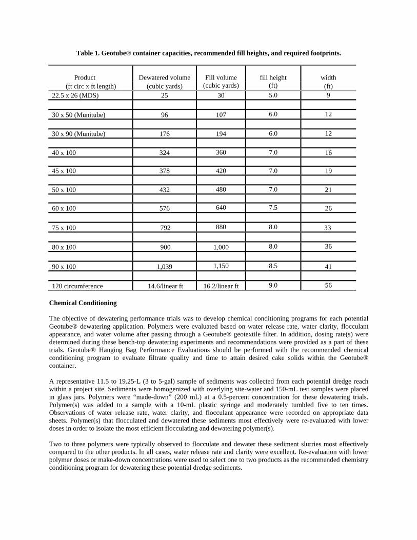
Table 1. Geotube® container capacities, recommended fill heights, and required footprints.
Product Dewatered volume Fill volume
fill height
width (ft circ x ft length) (cubic yards) (cubic yards) (ft) (ft) 22.5 x 26 (MDS) 25 30 5.0 9 30 x 50 (Munitube) 96 107 6.0 12 30 x 90 (Munitube) 176 194 6.0 12 40 x 100 324 360 7.0 16 45 x 100 378 420 7.0 19 50 x 100 432 480 7.0 21 60 x 100 576 640 7.5 26 75 x 100 792 880 8.0 33 80 x 100 900 1,000 8.0 36 90 x 100 1,039 1,150 8.5 41 120 circumference 14.6/linear ft 16.2/linear ft 9.0 56
Chemical Conditioning The objective of dewatering performance trials was to develop chemical conditioning programs for each potential Geotube® dewatering application. Polymers were evaluated based on water release rate, water clarity, flocculant appearance, and water volume after passing through a Geotube® geotextile filter. In addition, dosing rate(s) were determined during these bench-top dewatering experiments and recommendations were provided as a part of these trials. Geotube® Hanging Bag Performance Evaluations should be performed with the recommended chemical conditioning program to evaluate filtrate quality and time to attain desired cake solids within the Geotube® container. A representative 11.5 to 19.25-L (3 to 5-gal) sample of sediments was collected from each potential dredge reach within a project site. Sediments were homogenized with overlying site-water and 150-mL test samples were placed in glass jars. Polymers were “made-down” (200 mL) at a 0.5-percent concentration for these dewatering trials. Polymer(s) was added to a sample with a 10-mL plastic syringe and moderately tumbled five to ten times. Observations of water release rate, water clarity, and flocculant appearance were recorded on appropriate data sheets. Polymer(s) that flocculated and dewatered these sediments most effectively were re-evaluated with lower doses in order to isolate the most efficient flocculating and dewatering polymer(s). Two to three polymers were typically observed to flocculate and dewater these sediment slurries most effectively compared to the other products. In all cases, water release rate and clarity were excellent. Re-evaluation with lower polymer doses or make-down concentrations were used to select one to two products as the recommended chemistry conditioning program for dewatering these potential dredge sediments.
Once a recommended chemical conditioning program was identified, other chemical application variables were evaluated for potential full-scale operations including:
• Use of more than one chemistry during dredging operations as sediment character changes with depth, debris, organic matter, and density,
• Simultaneous or sequential application of more than one chemistry, • Application of an inorganic chemistry in combination with an organic chemistry, • Effects of mixing energy and shear energy during introduction of flocculating chemistry inline to a dredge
slurry pipeline to evaluate injection distance from the Geotubes®, and • Use of pre- and post-dilution to meet project objectives of Geotube® sediment dryness and/or filtrate
“quality”. Hanging bag performance evaluation Objectives This test method was used to measure 1) percent dry weight solids contained in a Geotube® container used to contain dredged material and 2) measure the concentration of suspended solids through a Geotube® container used to contain dredged material. Results of sediment that passed through the Geotube® container were shown as percent total suspended solids in milligrams per liter or parts per million.
This test method required several pieces of specified pieces of equipment, such as an analytical balance, a Geotube® container, a metal frame or scaffold to hold the Geotube® container, clean containers to collect the dredged material sediment, and a representative sample of dredged material from each proposed dredge area(s). The values stated in SI units were the standard, while the inch-pound units are provided for information. The values expressed in each system were not exact equivalents: therefore, each system must be used independently of the other, without combining values in any way. This standard did not purport to address all of material and site safety problems, if any, associated with its use. It was the responsibility of the user of this standard to establish appropriate safety and health practices for contaminated dredged materials and determine the applicability of regulatory limitations prior to use. Terminology • Dredged material-See proposed standard for dredged material terminology. • Filtration-See filter. • Filter-See Terminology D 653. • Geosynthetic, n-a planar product manufactured from polymeric material used with foundation soil, rock, earth,
or any other geotechnical engineering related material as an integral part of a man-made project, structure, or system. (See Practice D 4759.)
• Geotextile, n-any permeable textile material used with foundation, soil, rock, earth, or any other geotechnical engineering related material, as an integral part of a manmade project, structure, or system.
• Performance property, n-a result obtained by conducting a performance test. • Performance test, n-in geosynthetics, a laboratory procedure which simulates selected field conditions which
can be used in design. • For definitions of other terms relating to geosynthetics, refer to Terminology D 4439. For definitions of textile
terms, refer to Terminology D 123. For definitions of soil terms, refer to Terminology D 653. • Funnel, n-an apparatus that directs a liquid into a container. • Geotube® container, n-a bag, tube, sock, or container designed and fabricated from a combination or layers of
permeable non-woven and woven geotextile fabric to retain a maximum percent of fine grained dredged material for subsequent drainage and consolidation of the contained semi-fluid materials.
Summary of Test Method
A Geotube® container was constructed by sewing one or more layers of geotextile together to form a container that supported and contained a measured amount of saturated dredged material. The time and amount of sediment that flowed through the Geotube® container collected at given time intervals and was measured. The amount of sediment passing the Geotube® container was determined as the total suspended solids. Dredged material from each different area to be dredged was used in this test method. A chemical conditioning program was identified for each dredge material sample. Significance and Use This test method was used to determine percent and concentration of total suspended solids of sediment passing through a Geotube® container over a specified time period. This test method was used to design Geotube® container systems that contain fine-grained dredged materials to meet special environmental requirements of regulatory agencies and determined the amount of dredged material sediment passing a Geotube® and the flow rate for specific dredged material conditions. This test method was used to determine the quantity and percent dry weight solids of fine grained dredged material sediment that was contained in the Geotube® container. The designer used this test method to determine the quantity of fine grained dredged material sediment that passed through the Geotube® container into the environment.
This test method was intended as an index test for performance evaluation, as the results depended on the specific dredged materials evaluated and the location of the Geotube® container below or above water. This test method provided a means of evaluating Geotube® containers with different dredged materials under various conditions that simulated the conditions that exist with Geotube® contained dredged material. The number of times this test was repeated depends on the users and the site conditions. This test method evaluated the identified chemical conditioning program(s) for performance (e.g., water release, water clarity, and flock appearance) and dose on a field application scale. Apparatus
• Scaffolding or Metal Framing • Geotube® container with eight evenly space metal grommets, 114-cm (45-in) inside circumference, 165-
cm (65-in) length, approximate capacity filled about 142-cm (56-in) deep is about 175-L (40-gal). • Three shallow 25-cm deep, 610-cm diameter (10-in deep, 24-in diameter aluminum or plastic collection
pans (e.g., hot water heater drip pan, lexan storage container, etc.). • Two large 206-L (55-gal) containers approved for contaminated dredged material when required. • Stirrer, such as a paint mixer on a portable electric drill. • Dredged Material from the proposed dredge area. • Gooch Crucible. • Membrane Filter Apparatus. • Vacuum Pump. • Polymer(s) and other dewatering chemistry. • High speed blender. • Graduated cylinders – 200-mL and 1,000-mL
Sampling Geotube® Container: Lot Sample for Geotube® Container: Divide the product into lots and take the lot samples as directed in Practice D 4354. Geotube® Container Sample-After first discarding a minimum of 1 m (3.3 ft) of geotextile from the end of the roll, cut sufficient lengths to fabricate the number of containers for the appropriate number of tests. If holes or damaged areas are evident, then damaged areas should be discarded and additional material used. No fabric should be used within 15.2 cm (6 in) of a selvedged edge.
Dredged Material: Project engineers obtained representative samples from the proposed dredge area(s) at the Atterberg limits, in situ water content, consistency, density, grain size and depth that is representative of the soils and is significant to the design of Geotube® containers for fine-grained dredged material. The size and number of samples required is dependent upon the number of tests to be performed. Samples should be representative of the bulked dredged material density, water content, and consistency obtained in the Geotube® container after the dredging and placement operation. Procedure
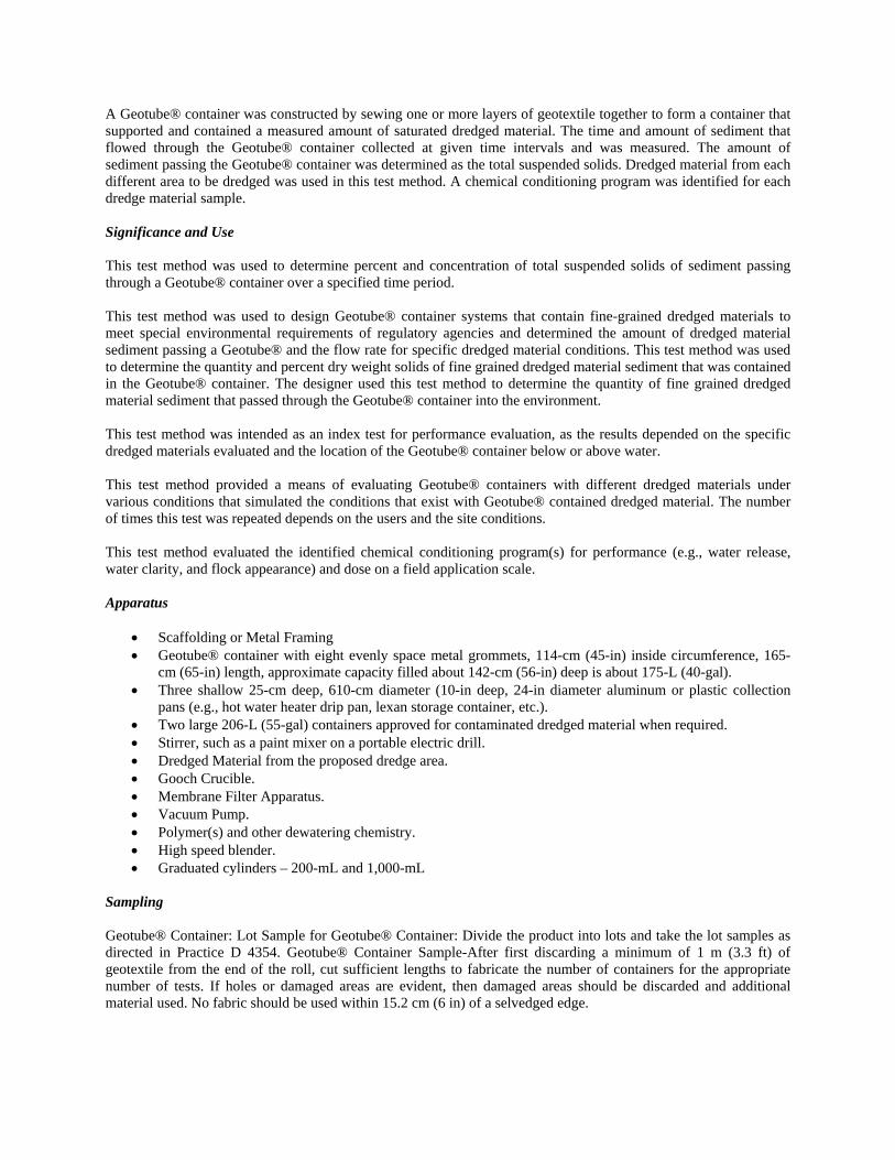
1. Geotube® containers provided by the manufacturer are constructed by sewing one or more geotextile layers of geotextile together to form a container 114-cm (45-in) inside circumference and 163-cm (64-in) long as shown in Figure 1A. A selvedged edge is provided along the circumference of the container opening. Eight 1.3-cm (0.5-in) diameter metal grommets are evenly spaced about 2.5-cm (1.0-in) from the selvedged edge. Fabric seams are constructed by two double lock stitches to contain the dredged material, as it would be in the prototype.
2. Attach the Geotube® container to the sheet metal pipe with 1-cm (0.39-in) galvanized bolts, washers and
nuts through the eight evenly spaced metal grommets. The bottom of the container should have a clearance of about 15 to 20-cm (6 to 8-in) above the floor of the platform to accommodate removal the collection pans as they fill with sediment and water.
3. After the Geotube® container is suspended from the scaffolding, a collector pan is placed under the
Geotube® container to collect water and sediment by gravity flow (Figure 1A).
A B
Figure 1. A) Geotube® hanging bag dewatering performance trial. B) Sediments were collected for analytical testing (e.g., contaminants, percent dry weight solids).
4. Obtain about 150 to 190 L (40 to 50 gal) of the site specific dredged material in a 208-L container (55-gal)
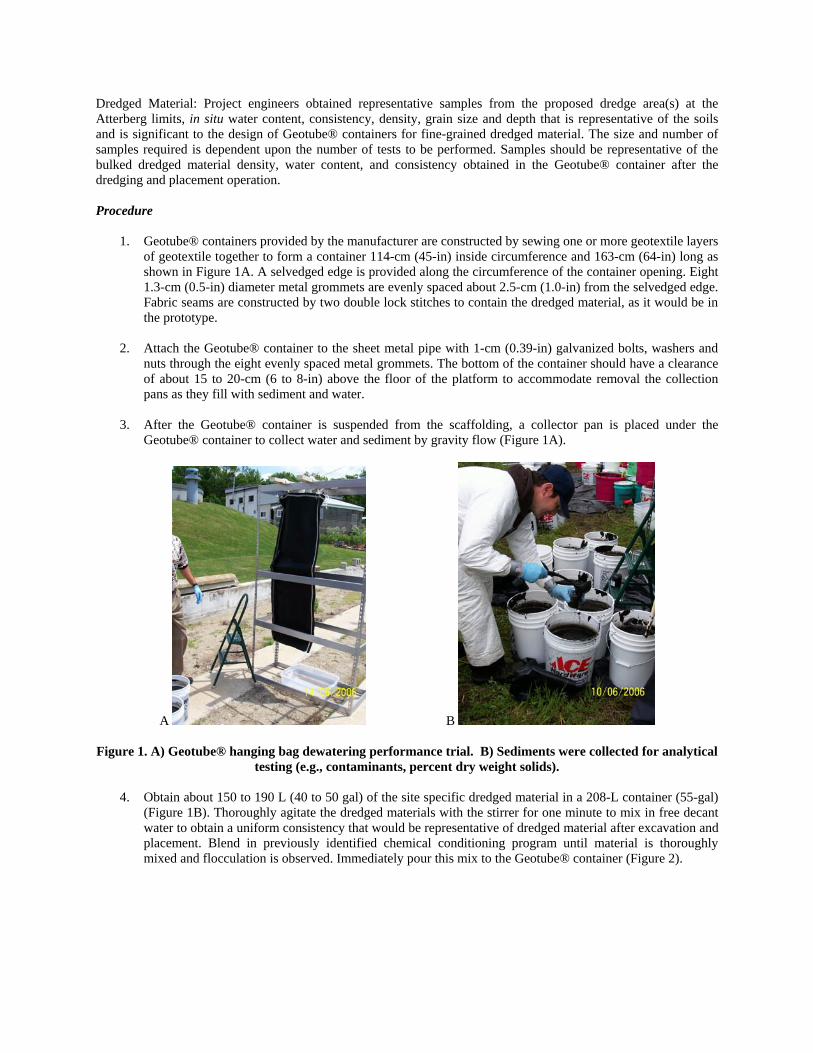
(Figure 1B). Thoroughly agitate the dredged materials with the stirrer for one minute to mix in free decant water to obtain a uniform consistency that would be representative of dredged material after excavation and placement. Blend in previously identified chemical conditioning program until material is thoroughly mixed and flocculation is observed. Immediately pour this mix to the Geotube® container (Figure 2).
A B C
Figure 2. A) Identified chemical conditioning polymer is “made-down” at 0.5-percent concentration and confirmatory bench test performed to verify dose. B) The calculated dose of made-down polymer is added to
each five gallon pail and stirred to achieve a sufficient flock and release of free water (C).
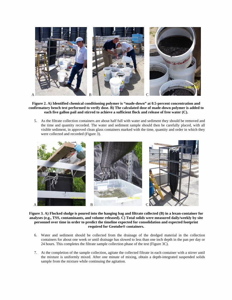
5. As the filtrate collection containers are about half full with water and sediment they should be removed and the time and quantity recorded. The water and sediment sample should then be carefully placed, with all visible sediment, in approved clean glass containers marked with the time, quantity and order in which they were collected and recorded (Figure 3).
A B C Figure 3. A) Flocked sludge is poured into the hanging bag and filtrate collected (B) in a lexan-container for analyses (e.g., TSS, contaminants, and volume released). C) Total solids were measured daily/weekly by site
personnel over time in order to predict the timeline expected for consolidation and expected footprint required for Geotube® containers.
6. Water and sediment should be collected from the drainage of the dredged material in the collection
containers for about one week or until drainage has slowed to less than one inch depth in the pan per day or 24 hours. This completes the filtrate sample collection phase of the test (Figure 3C).
7. At the completion of the sample collection, agitate the collected filtrate in each container with a stirrer until
the mixture is uniformly mixed. After one minute of mixing, obtain a depth-integrated suspended solids sample from the mixture while continuing the agitation.
8. Place a glass fiber filter disk either on a membrane filter apparatus or in the bottom of a suitable Gooch crucible. Apply a vacuum and wash the disk with three successive 20-mL portion of distilled water. Continue suction to remove all traces of water from the disk.
9. Carefully remove the filter disk from the membrane filter apparatus and transfer to an aluminum or
stainless steel planchet. If a Gooch crucible is used, remove the crucible and filter disk combination.
10. Dry the filter disk for at least 1 hour in an oven at 103 to 105oC.
11. Store in a desiccator until cooled to room temperature.
12. Weigh the filter disk to an accuracy of 0.00001 g.
13. Place the filter disk in the membrane filter apparatus and return it or the Gooch crucible to the vacuuming and filtering apparatus.
14. Under the vacuum, filter the sample of water collected in 8.7
15. Repeat 9 through 12.
Calculation Calculate total suspended solids, as follow: (A - B) x 1000 Ss = ----------------- (1) C where: Ss = suspended solids, ppm, A = weight of dry filter plus dry residue, and B = weight of dry filter, and C = sample volume of suspended material, mL
CASE STUDY #1- LITTLE LAKE BUTTE DES MORTS, CH2MHILL, APPLETON, WI Objective The 2004 objectives of this U.S. EPA (USEPA) and Wisconsin Department of Natural Resources (WDNR) Superfund Site Cleanup Project were:
1) Dredge contaminated sediments from two locations in Little Lake Butte des Morts, 2) Pump the contaminated sediments through a floating pipeline to a near-shore processing area, 3) Separate the contaminated sediments from the associated water, 4) Treat the separated water and discharge it back into the lake, and 5) Truck the dried sediments to an approved disposal facility beginning in 2005.
Geotube® container sizing Approximately 20,000 cubic yards of in situ sediments at 15 to 20-percent dry weight solids were targeted for dredging (10 hours per day, six days per week) in 2004. It was calculated that 5,500 linear feet of 60-ft circumference Geotube® container would be needed to dewater and contain this volume to greater than 35-percent dry weight solids, sufficiently dry to pass a paint filter test, haul off site, and be accepted into a licensed landfill. The resulting volume and mass of residuals at 35-percent dry weight solids would be less than 8,500 cubic yards and 7,200 tons, respectively. An operational goal of this project was to hydraulically dredge at an average flow rate of 1,100 gallons per minute.
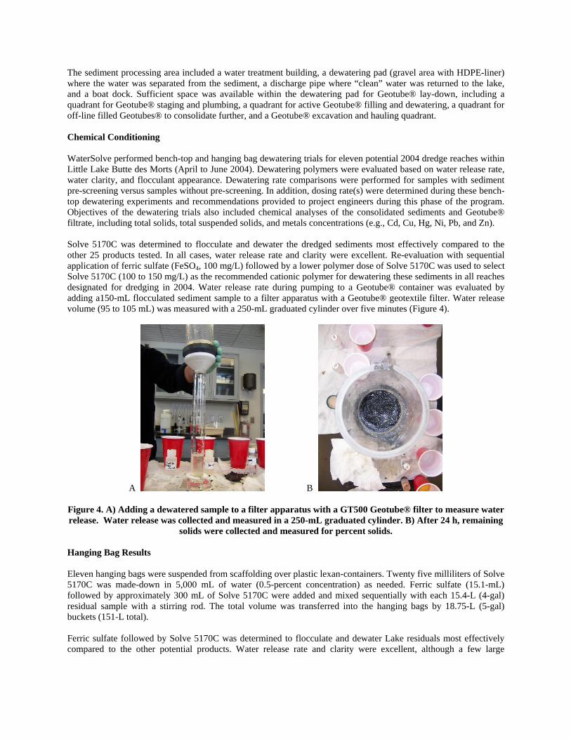
The sediment processing area included a water treatment building, a dewatering pad (gravel area with HDPE-liner) where the water was separated from the sediment, a discharge pipe where “clean” water was returned to the lake, and a boat dock. Sufficient space was available within the dewatering pad for Geotube® lay-down, including a quadrant for Geotube® staging and plumbing, a quadrant for active Geotube® filling and dewatering, a quadrant for off-line filled Geotubes® to consolidate further, and a Geotube® excavation and hauling quadrant. Chemical Conditioning WaterSolve performed bench-top and hanging bag dewatering trials for eleven potential 2004 dredge reaches within Little Lake Butte des Morts (April to June 2004). Dewatering polymers were evaluated based on water release rate, water clarity, and flocculant appearance. Dewatering rate comparisons were performed for samples with sediment pre-screening versus samples without pre-screening. In addition, dosing rate(s) were determined during these bench-top dewatering experiments and recommendations provided to project engineers during this phase of the program. Objectives of the dewatering trials also included chemical analyses of the consolidated sediments and Geotube® filtrate, including total solids, total suspended solids, and metals concentrations (e.g., Cd, Cu, Hg, Ni, Pb, and Zn). Solve 5170C was determined to flocculate and dewater the dredged sediments most effectively compared to the other 25 products tested. In all cases, water release rate and clarity were excellent. Re-evaluation with sequential application of ferric sulfate (FeSO4, 100 mg/L) followed by a lower polymer dose of Solve 5170C was used to select Solve 5170C (100 to 150 mg/L) as the recommended cationic polymer for dewatering these sediments in all reaches designated for dredging in 2004. Water release rate during pumping to a Geotube® container was evaluated by adding a150-mL flocculated sediment sample to a filter apparatus with a Geotube® geotextile filter. Water release volume (95 to 105 mL) was measured with a 250-mL graduated cylinder over five minutes (Figure 4).
A B
Figure 4. A) Adding a dewatered sample to a filter apparatus with a GT500 Geotube® filter to measure water release. Water release was collected and measured in a 250-mL graduated cylinder. B) After 24 h, remaining
solids were collected and measured for percent solids.
Hanging Bag Results Eleven hanging bags were suspended from scaffolding over plastic lexan-containers. Twenty five milliliters of Solve 5170C was made-down in 5,000 mL of water (0.5-percent concentration) as needed. Ferric sulfate (15.1-mL) followed by approximately 300 mL of Solve 5170C were added and mixed sequentially with each 15.4-L (4-gal) residual sample with a stirring rod. The total volume was transferred into the hanging bags by 18.75-L (5-gal) buckets (151-L total). Ferric sulfate followed by Solve 5170C was determined to flocculate and dewater Lake residuals most effectively compared to the other potential products. Water release rate and clarity were excellent, although a few large
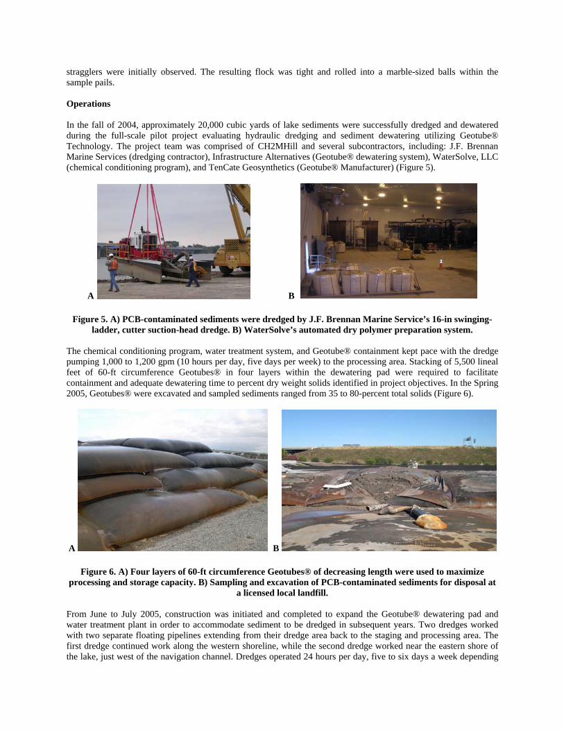
stragglers were initially observed. The resulting flock was tight and rolled into a marble-sized balls within the sample pails. Operations In the fall of 2004, approximately 20,000 cubic yards of lake sediments were successfully dredged and dewatered during the full-scale pilot project evaluating hydraulic dredging and sediment dewatering utilizing Geotube® Technology. The project team was comprised of CH2MHill and several subcontractors, including: J.F. Brennan Marine Services (dredging contractor), Infrastructure Alternatives (Geotube® dewatering system), WaterSolve, LLC (chemical conditioning program), and TenCate Geosynthetics (Geotube® Manufacturer) (Figure 5).
A B
Figure 5. A) PCB-contaminated sediments were dredged by J.F. Brennan Marine Service’s 16-in swinging-ladder, cutter suction-head dredge. B) WaterSolve’s automated dry polymer preparation system.
The chemical conditioning program, water treatment system, and Geotube® containment kept pace with the dredge pumping 1,000 to 1,200 gpm (10 hours per day, five days per week) to the processing area. Stacking of 5,500 lineal feet of 60-ft circumference Geotubes® in four layers within the dewatering pad were required to facilitate containment and adequate dewatering time to percent dry weight solids identified in project objectives. In the Spring 2005, Geotubes® were excavated and sampled sediments ranged from 35 to 80-percent total solids (Figure 6).
A B
Figure 6. A) Four layers of 60-ft circumference Geotubes® of decreasing length were used to maximize processing and storage capacity. B) Sampling and excavation of PCB-contaminated sediments for disposal at
a licensed local landfill. From June to July 2005, construction was initiated and completed to expand the Geotube® dewatering pad and water treatment plant in order to accommodate sediment to be dredged in subsequent years. Two dredges worked with two separate floating pipelines extending from their dredge area back to the staging and processing area. The first dredge continued work along the western shoreline, while the second dredge worked near the eastern shore of the lake, just west of the navigation channel. Dredges operated 24 hours per day, five to six days a week depending
on weather conditions. Global Positioning Systems (GPS) were installed to aid in locating designated hotspots for PCB removal. By the end of the third year of dredging operations (2004-2006), Wisconsin DNR and USEPA estimated 1,227 kg (2,700 lb) of the 1,864 kg (4,100 lb) of PCB mass contained in Little Lake Butte des Morts sediments were removed and properly disposed (Hickory Meadows Landfill, Chilton, WI). Excavation and hauling of dewatered sediment is scheduled to continue through the winter and in-water work is expected to resume in spring 2007. The 2006 project team was comprised of J.F. Brennan Marine Services (dredging contractor), CIBA (operations of chemical conditioning system), and TenCate Geosynthetics (Geotube® Manufacturer).
CASE STUDY #2- OLDHAM COUNTY STONE, ROGERS GROUP & KENTUCKY DREDGE, CRESTWOOD, KENTUCKY
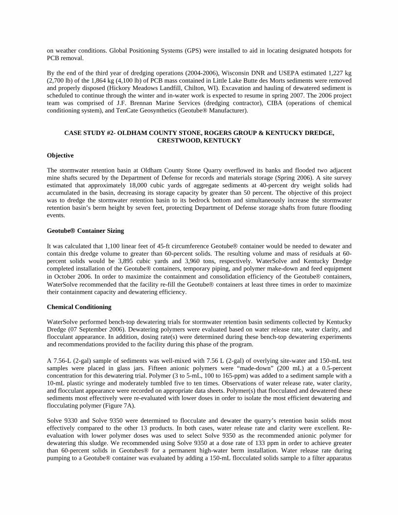
Objective The stormwater retention basin at Oldham County Stone Quarry overflowed its banks and flooded two adjacent mine shafts secured by the Department of Defense for records and materials storage (Spring 2006). A site survey estimated that approximately 18,000 cubic yards of aggregate sediments at 40-percent dry weight solids had accumulated in the basin, decreasing its storage capacity by greater than 50 percent. The objective of this project was to dredge the stormwater retention basin to its bedrock bottom and simultaneously increase the stormwater retention basin’s berm height by seven feet, protecting Department of Defense storage shafts from future flooding events. Geotube® Container Sizing It was calculated that 1,100 linear feet of 45-ft circumference Geotube® container would be needed to dewater and contain this dredge volume to greater than 60-percent solids. The resulting volume and mass of residuals at 60-percent solids would be 3,895 cubic yards and 3,960 tons, respectively. WaterSolve and Kentucky Dredge completed installation of the Geotube® containers, temporary piping, and polymer make-down and feed equipment in October 2006. In order to maximize the containment and consolidation efficiency of the Geotube® containers, WaterSolve recommended that the facility re-fill the Geotube® containers at least three times in order to maximize their containment capacity and dewatering efficiency. Chemical Conditioning WaterSolve performed bench-top dewatering trials for stormwater retention basin sediments collected by Kentucky Dredge (07 September 2006). Dewatering polymers were evaluated based on water release rate, water clarity, and flocculant appearance. In addition, dosing rate(s) were determined during these bench-top dewatering experiments and recommendations provided to the facility during this phase of the program. A 7.56-L (2-gal) sample of sediments was well-mixed with 7.56 L (2-gal) of overlying site-water and 150-mL test samples were placed in glass jars. Fifteen anionic polymers were “made-down” (200 mL) at a 0.5-percent concentration for this dewatering trial. Polymer (3 to 5-mL, 100 to 165-ppm) was added to a sediment sample with a 10-mL plastic syringe and moderately tumbled five to ten times. Observations of water release rate, water clarity, and flocculant appearance were recorded on appropriate data sheets. Polymer(s) that flocculated and dewatered these sediments most effectively were re-evaluated with lower doses in order to isolate the most efficient dewatering and flocculating polymer (Figure 7A). Solve 9330 and Solve 9350 were determined to flocculate and dewater the quarry’s retention basin solids most effectively compared to the other 13 products. In both cases, water release rate and clarity were excellent. Re-evaluation with lower polymer doses was used to select Solve 9350 as the recommended anionic polymer for dewatering this sludge. We recommended using Solve 9350 at a dose rate of 133 ppm in order to achieve greater than 60-percent solids in Geotubes® for a permanent high-water berm installation. Water release rate during pumping to a Geotube® container was evaluated by adding a 150-mL flocculated solids sample to a filter apparatus
with a Geotube® geotextile filter. Eighty-five milliliters of water was released and measured with a 250-mL graduated cylinder over five minutes (Figures 7B and C).
A B C
Figure 7. A) Retention basin sediments in a 250-mL sample jar after addition of Solve 9350 (133 ppm) and release of free water. B) Adding dewatered sample to filter apparatus with a GT500 Geotube® filter to
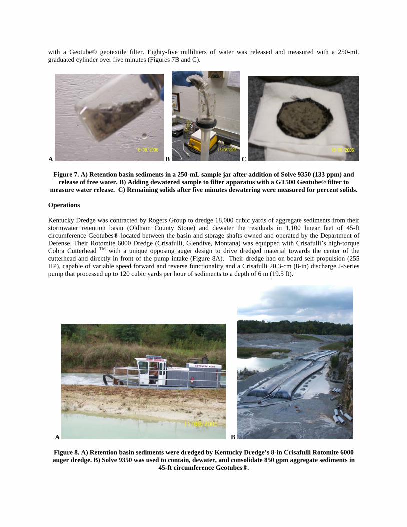
measure water release. C) Remaining solids after five minutes dewatering were measured for percent solids. Operations Kentucky Dredge was contracted by Rogers Group to dredge 18,000 cubic yards of aggregate sediments from their stormwater retention basin (Oldham County Stone) and dewater the residuals in 1,100 linear feet of 45-ft circumference Geotubes® located between the basin and storage shafts owned and operated by the Department of Defense. Their Rotomite 6000 Dredge (Crisafulli, Glendive, Montana) was equipped with Crisafulli’s high-torque Cobra Cutterhead TM with a unique opposing auger design to drive dredged material towards the center of the cutterhead and directly in front of the pump intake (Figure 8A). Their dredge had on-board self propulsion (255 HP), capable of variable speed forward and reverse functionality and a Crisafulli 20.3-cm (8-in) discharge J-Series pump that processed up to 120 cubic yards per hour of sediments to a depth of 6 m (19.5 ft).
A B
Figure 8. A) Retention basin sediments were dredged by Kentucky Dredge’s 8-in Crisafulli Rotomite 6000 auger dredge. B) Solve 9350 was used to contain, dewater, and consolidate 850 gpm aggregate sediments in
45-ft circumference Geotubes®.
Sediments were chemically conditioned (Solve 9350) in-line with WaterSolve’s WSLP-2400USF polymer make-down unit and initially dredged into four Geotube® containers (45-ft circumference x 100 linear feet) at 850 gpm over three days (Figure 8B). As the first 400 ft of Geotube® containers approached 75-percent solids capacity, two 45-ft circumference x 200-ft long Geotube® containers were brought online. The first containers were pulse-filled to capacity and the remaining volume was pumped to the second set of Geotube® containers. Two weeks of dredging were required to fill all 1,100 ft of Geotube® containers to 90 percent of dewatered volume capacity with greater than 85-percent dry weight solids remaining. Overall, dredging of this stormwater basin required an additional 30 hours of dredge time over projection to utilize the capacity of the Geotubes and obtain 2.12-m (7-ft) berm height (Figure 8B).
CASE STUDY #3- WASTEWATER TREATMENT PLANT BIOSOLIDS LAGOONS, MASSANA DREDGING, FORSYTH, GEORGIA
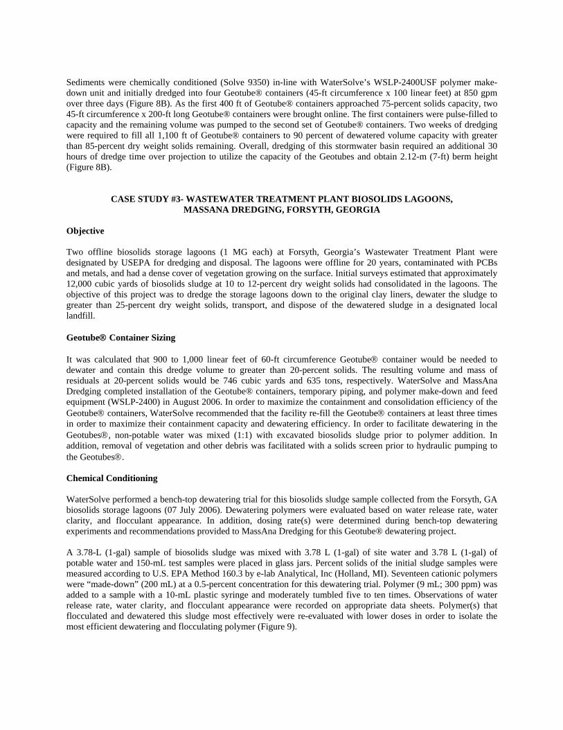
Objective Two offline biosolids storage lagoons (1 MG each) at Forsyth, Georgia’s Wastewater Treatment Plant were designated by USEPA for dredging and disposal. The lagoons were offline for 20 years, contaminated with PCBs and metals, and had a dense cover of vegetation growing on the surface. Initial surveys estimated that approximately 12,000 cubic yards of biosolids sludge at 10 to 12-percent dry weight solids had consolidated in the lagoons. The objective of this project was to dredge the storage lagoons down to the original clay liners, dewater the sludge to greater than 25-percent dry weight solids, transport, and dispose of the dewatered sludge in a designated local landfill. Geotube® Container Sizing It was calculated that 900 to 1,000 linear feet of 60-ft circumference Geotube® container would be needed to dewater and contain this dredge volume to greater than 20-percent solids. The resulting volume and mass of residuals at 20-percent solids would be 746 cubic yards and 635 tons, respectively. WaterSolve and MassAna Dredging completed installation of the Geotube® containers, temporary piping, and polymer make-down and feed equipment (WSLP-2400) in August 2006. In order to maximize the containment and consolidation efficiency of the Geotube® containers, WaterSolve recommended that the facility re-fill the Geotube® containers at least three times in order to maximize their containment capacity and dewatering efficiency. In order to facilitate dewatering in the Geotubes®, non-potable water was mixed (1:1) with excavated biosolids sludge prior to polymer addition. In addition, removal of vegetation and other debris was facilitated with a solids screen prior to hydraulic pumping to the Geotubes®. Chemical Conditioning WaterSolve performed a bench-top dewatering trial for this biosolids sludge sample collected from the Forsyth, GA biosolids storage lagoons (07 July 2006). Dewatering polymers were evaluated based on water release rate, water clarity, and flocculant appearance. In addition, dosing rate(s) were determined during bench-top dewatering experiments and recommendations provided to MassAna Dredging for this Geotube® dewatering project. A 3.78-L (1-gal) sample of biosolids sludge was mixed with 3.78 L (1-gal) of site water and 3.78 L (1-gal) of potable water and 150-mL test samples were placed in glass jars. Percent solids of the initial sludge samples were measured according to U.S. EPA Method 160.3 by e-lab Analytical, Inc (Holland, MI). Seventeen cationic polymers were “made-down” (200 mL) at a 0.5-percent concentration for this dewatering trial. Polymer (9 mL; 300 ppm) was added to a sample with a 10-mL plastic syringe and moderately tumbled five to ten times. Observations of water release rate, water clarity, and flocculant appearance were recorded on appropriate data sheets. Polymer(s) that flocculated and dewatered this sludge most effectively were re-evaluated with lower doses in order to isolate the most efficient dewatering and flocculating polymer (Figure 9).
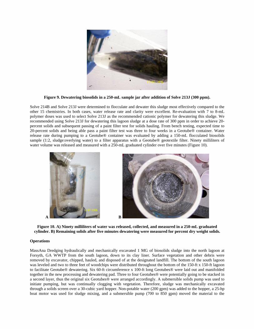
Figure 9. Dewatering biosolids in a 250-mL sample jar after addition of Solve 213J (300 ppm).
Solve 214B and Solve 213J were determined to flocculate and dewater this sludge most effectively compared to the other 15 chemistries. In both cases, water release rate and clarity were excellent. Re-evaluation with 7 to 8-mL polymer doses was used to select Solve 213J as the recommended cationic polymer for dewatering this sludge. We recommended using Solve 213J for dewatering this lagoon sludge at a dose rate of 300 ppm in order to achieve 20-percent solids and subsequent passing of a paint filter test for solids hauling. From bench testing, expected time to 20-percent solids and being able pass a paint filter test was three to four weeks in a Geotube® container. Water release rate during pumping to a Geotube® container was evaluated by adding a 150-mL flocculated biosolids sample (1:2, sludge:overlying water) to a filter apparatus with a Geotube® geotextile filter. Ninety milliliters of water volume was released and measured with a 250-mL graduated cylinder over five minutes (Figure 10).
A B
Figure 10. A) Ninety milliliters of water was released, collected, and measured in a 250-mL graduated cylinder. B) Remaining solids after five minutes dewatering were measured for percent dry weight solids.
Operations MassAna Dredging hydraulically and mechanically excavated 1 MG of biosolids sludge into the north lagoon at Forsyth, GA WWTP from the south lagoon, down to its clay liner. Surface vegetation and other debris were removed by excavator, chipped, hauled, and disposed of at the designated landfill. The bottom of the south lagoon was leveled and two to three feet of woodchips were distributed throughout the bottom of the 150-ft x 150-ft lagoon to facilitate Geotube® dewatering. Six 60-ft circumference x 100-ft long Geotubes® were laid out and manifolded together in the new processing and dewatering pad. Three to four Geotubes® were potentially going to be stacked in a second layer, thus the original six Geotubes® were arranged accordingly. A submersible solids pump was used to initiate pumping, but was continually clogging with vegetation. Therefore, sludge was mechanically excavated through a solids screen over a 30-cubic yard hopper. Non-potable water (200 gpm) was added to the hopper, a 25-hp boat motor was used for sludge mixing, and a submersible pump (700 to 850 gpm) moved the material to the
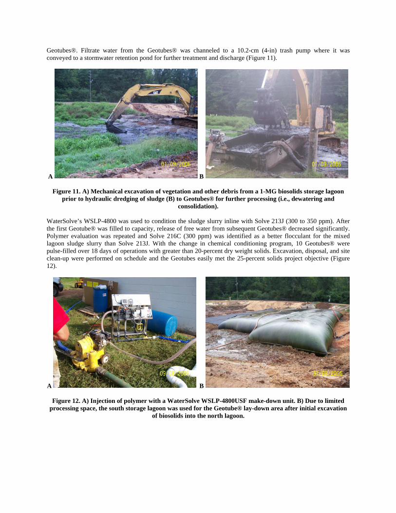
Geotubes®. Filtrate water from the Geotubes® was channeled to a 10.2-cm (4-in) trash pump where it was conveyed to a stormwater retention pond for further treatment and discharge (Figure 11).
A B
Figure 11. A) Mechanical excavation of vegetation and other debris from a 1-MG biosolids storage lagoon prior to hydraulic dredging of sludge (B) to Geotubes® for further processing (i.e., dewatering and
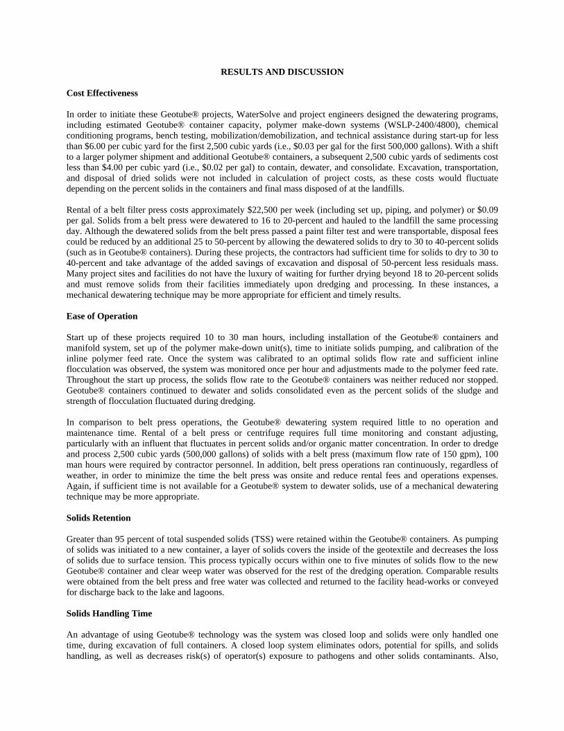
consolidation). WaterSolve’s WSLP-4800 was used to condition the sludge slurry inline with Solve 213J (300 to 350 ppm). After the first Geotube® was filled to capacity, release of free water from subsequent Geotubes® decreased significantly. Polymer evaluation was repeated and Solve 216C (300 ppm) was identified as a better flocculant for the mixed lagoon sludge slurry than Solve 213J. With the change in chemical conditioning program, 10 Geotubes® were pulse-filled over 18 days of operations with greater than 20-percent dry weight solids. Excavation, disposal, and site clean-up were performed on schedule and the Geotubes easily met the 25-percent solids project objective (Figure 12).
A B
Figure 12. A) Injection of polymer with a WaterSolve WSLP-4800USF make-down unit. B) Due to limited processing space, the south storage lagoon was used for the Geotube® lay-down area after initial excavation
of biosolids into the north lagoon.
RESULTS AND DISCUSSION Cost Effectiveness In order to initiate these Geotube® projects, WaterSolve and project engineers designed the dewatering programs, including estimated Geotube® container capacity, polymer make-down systems (WSLP-2400/4800), chemical conditioning programs, bench testing, mobilization/demobilization, and technical assistance during start-up for less than $6.00 per cubic yard for the first 2,500 cubic yards (i.e., $0.03 per gal for the first 500,000 gallons). With a shift to a larger polymer shipment and additional Geotube® containers, a subsequent 2,500 cubic yards of sediments cost less than $4.00 per cubic yard (i.e., $0.02 per gal) to contain, dewater, and consolidate. Excavation, transportation, and disposal of dried solids were not included in calculation of project costs, as these costs would fluctuate depending on the percent solids in the containers and final mass disposed of at the landfills. Rental of a belt filter press costs approximately $22,500 per week (including set up, piping, and polymer) or $0.09 per gal. Solids from a belt press were dewatered to 16 to 20-percent and hauled to the landfill the same processing day. Although the dewatered solids from the belt press passed a paint filter test and were transportable, disposal fees could be reduced by an additional 25 to 50-percent by allowing the dewatered solids to dry to 30 to 40-percent solids (such as in Geotube® containers). During these projects, the contractors had sufficient time for solids to dry to 30 to 40-percent and take advantage of the added savings of excavation and disposal of 50-percent less residuals mass. Many project sites and facilities do not have the luxury of waiting for further drying beyond 18 to 20-percent solids and must remove solids from their facilities immediately upon dredging and processing. In these instances, a mechanical dewatering technique may be more appropriate for efficient and timely results. Ease of Operation Start up of these projects required 10 to 30 man hours, including installation of the Geotube® containers and manifold system, set up of the polymer make-down unit(s), time to initiate solids pumping, and calibration of the inline polymer feed rate. Once the system was calibrated to an optimal solids flow rate and sufficient inline flocculation was observed, the system was monitored once per hour and adjustments made to the polymer feed rate. Throughout the start up process, the solids flow rate to the Geotube® containers was neither reduced nor stopped. Geotube® containers continued to dewater and solids consolidated even as the percent solids of the sludge and strength of flocculation fluctuated during dredging. In comparison to belt press operations, the Geotube® dewatering system required little to no operation and maintenance time. Rental of a belt press or centrifuge requires full time monitoring and constant adjusting, particularly with an influent that fluctuates in percent solids and/or organic matter concentration. In order to dredge and process 2,500 cubic yards (500,000 gallons) of solids with a belt press (maximum flow rate of 150 gpm), 100 man hours were required by contractor personnel. In addition, belt press operations ran continuously, regardless of weather, in order to minimize the time the belt press was onsite and reduce rental fees and operations expenses. Again, if sufficient time is not available for a Geotube® system to dewater solids, use of a mechanical dewatering technique may be more appropriate. Solids Retention Greater than 95 percent of total suspended solids (TSS) were retained within the Geotube® containers. As pumping of solids was initiated to a new container, a layer of solids covers the inside of the geotextile and decreases the loss of solids due to surface tension. This process typically occurs within one to five minutes of solids flow to the new Geotube® container and clear weep water was observed for the rest of the dredging operation. Comparable results were obtained from the belt press and free water was collected and returned to the facility head-works or conveyed for discharge back to the lake and lagoons. Solids Handling Time An advantage of using Geotube® technology was the system was closed loop and solids were only handled one time, during excavation of full containers. A closed loop system eliminates odors, potential for spills, and solids handling, as well as decreases risk(s) of operator(s) exposure to pathogens and other solids contaminants. Also,
Geotube® operations of this magnitude typically occur over days compared to a weeks of continuous operations with a belt press or centrifuge. With a belt press system, solids are open to the atmosphere, potentially release volatiles and associated odors, are excessively noisy, can spill off the belt onto the ground if blinding occurs due to insufficient flocculation, and increases potential risk(s) of operator exposure to solids contaminants. Flow and Volume Rates Flow rates (100 to 2,000 gpm) to Geotube® containers are dependant on equipment available on site, hiring of a contractor, or by renting from an equipment company. Solids from these projects were pumped with onsite equipment to Geotube® containers at 100 to 300 cubic yards per hour (700 to 2,000 gpm). In comparison, a 0.5-m belt press (a typical belt size for a truck mounted rental unit) has a maximum solids flow rate of 150 gpm (45 cubic yards per hour). There are very few reasons to stop the flow of solids to a Geotube® system except potentially changing an empty polymer drum/tote, shifting solids flow from a full container to a new container, and during shut down of operations to make inline design changes. In comparison, belt press operations are typically considered efficient at greater than 75 percent working operations. Seasonality Pumping of solids to a new Geotube® container can occur during any time of the year as long as polymer feed lines and solids lines are freeze protected. Pumping of solids to a partially filled container with frozen solids is not recommended due to inefficient dewatering and filling and the potential for overfilling. However, allowing a full or partially full Geotube® container to sit outside during a freeze/thaw cycle typically “cracks out” (i.e., releases) additional free water and will not harm the container. A belt press is capable of operating through all seasons, as long as the polymer feed lines and solids lines are freeze protected. A belt press requires constant operator supervision, regardless of the weather (e.g., rain, snow, freezing temperatures, etc.). In comparison, a Geotube® system is hands off after daily startup and calibration and an operator may not have to revisit the system during his/her shift, depending on the variability of the solids feed rate and inline percent solids. However, permanent inline mechanical dewatering techniques that are situated in a climate-controlled designated building are capable of operations 365 days per year. Footprint The footprint required for two 60-ft circumference x 100-ft long Geotube® containers was 555 square meters (6,050 square feet), sufficient to collect weep water from the Geotube® containers and channel it back to the facility. Geotube® containers were site-specific manufactured to fit the facility’s available footprint (Table 1). For solids dewatering, containers are manufactured in 30-ft to 120-ft circumferences in 5-ft increments with lengths of 50-ft to 400-ft. Standard Geotube® sizes designed for containment of solids can hold between 20 and 1,750 cubic yards of material. In comparison, a mechanical dewatering technique may be better suited for sites with a large volume of solids or sites that have limited space for an appropriately sized Geotube® lay-down area. A difficulty of using Geotube® containers in these situations is the large footprint required to contain the volume as well as being able to keep up with the production rate of these solids. Facilities in urban settings typically do not have the space available for a Geotube® dewatering system and would have to make some capital improvements to accommodate these systems. Geotube® systems are typically utilized at these larger sites to contain solids from a lake, river, and/or lagoon as back-up storage capacity to a mechanical dewatering device that may be down for repairs or maintenance.
CONCLUSIONS Geotube® containers were evaluated as a solids dewatering option and compared to a belt press operation at three project sites, including cost effectiveness, ease of operation, solids retention, solids handling time, flow and volume rates, seasonality, and footprint required to operate. Geotube® containers, with the aid of dewatering polymers, were recommended to and implemented by all three contractors into which solids were dredged and pumped directly into Geotube® containers. Geotube® dewatering methodology reduced the volume and mass of residual solids and is
expected to save the contractors 50 percent of the costs associated with hauling and disposal while allowing continual operations of the project sites. Overall, containment and dewatering of solids with Geotube® containers (including dewatering polymer and feed equipment) costs less than $0.02 per gal (greater than 2,500 cubic yards in situ), requires minimal technical assistance to install and operate, retained greater than 95-percent solids, solids were only handled once they were dried sufficiently for hauling and disposal (18 to 40-percent cake solids), did not interfere with site and facility operations, and the lay-down area for containment of 1,000 cubic yards of solids production was 555 square meters (6,050 square ft).
REFERENCES Fowler, J., Bagby, R.M., and Trainer, E. (1995). “Dewatering sewage sludge with geotextile tubes.” Environmental
Effects of Dredging Technical Notes, U.S. Army Engineer, Waterways Experiment Station, Vicksburg, MS. Fowler, J., Duke, M., Schmidt, M.L., Crabtree, B., Bagby, R.M., and Trainer, E. (1996). “Dewatering sewage
sludge and hazardous sludge with geotextile tubes.” Environmental Effects of Dredging Technical Notes, U.S. Army Engineer, Waterways Experiment Station, Vicksburg, MS.
Henderson, R.T., and Schultz, S.T. (1999). “Centrifuges versus belt presses in San Bernardino, California.” Proceedings of EF/AWWA Joint Residuals and Biosolids Management Conference: Strategic Networking for the 21st Century, Water Environment Federation, Arlington, VA.
Hummer, C.W., Jr. (1998). “DOER: A major dredging research programme.” Terra et Aqua, No. 72, September, pp. 13-17.
Palermo, M.R. (2000). “Disposal and placement of dredged material.” Handbook of Dredging Engineering, Second Edition, McGraw-Hill, New York, New York, pp. 11.1-11.52.
Taylor, M., Sprague, C.J., Elliot, D., and McGee, S. (2000). Paper mill sludge dewatering using dredge-filled geotextile tubes. Internal report, TenCate Nicolon and The Fletcher Group, Greenville, SC.
TenCate Geosynthetics (2005). Containment and Dewatering. www.geotube.com. U.S. Army Corps of Engineers (1987). Confined Disposal of Dredged Material. Engineer Manual, 1110-2-5027,
Office, Chief of Engineers, Washington, D.C. U.S. Army Corps of Engineers and U.S. Environmental Protection Agency (1992). Evaluating Environmental
Effects of Dredge Material Management Alternatives – A Technical Framework. EPA842-B-92-008, U.S. Environmental Protection Agency and U.S. Army Corps of Engineers, Washington, D.C., (http://www.epa.gov/OWOW/oceans/framework).
U.S. Environmental Protection Agency (1993). Selecting Remediation Technique for Contaminated Sediments. Office of Water, EPA-823-b93-001, U.S. Environmental Protection Agency, Washington, D.C.
U.S. Environmental Protection Agency (1994). Assessment and Remediation of Contaminated Sediments (ARCS) Program. Remediation Guidance Document, Great Lakes National Program Office, EPA 905-R94-003, U.S. Environmental Protection Agency, Chicago, IL.
U.S. Environmental Protection Agency (2000a). Biosolids Technology Fact Sheet; Belt Filter Press. EPA 832-F-00- 057, Washington, D.C.
U.S. Environmental Protection Agency (2000b). Biosolids Technology Fact Sheet; Centrifuge Thickening and Dewatering. EPA 832-F-00-053, Washington, D.C.
ACKNOWLEDGEMENTS The authors thank Infrastructure Alternatives, Kentucky Dredge, and MassAna Dredging for assistance in collecting Geotube® data onsite and the cooperation of their staffs while putting these projects online and evaluating the systems for effectiveness and efficiency.