Embed Size (px)
Citation preview
VECTRIX VX SERIES GRAPHICS SYSTEM USER I S MANUAL
(c) Vectrix Corporation 1983
July 1983
Vectrix Corporation 1416 Boston Road Greensboro, NC 27407 (800) 334-8181 or (919) 294-6640
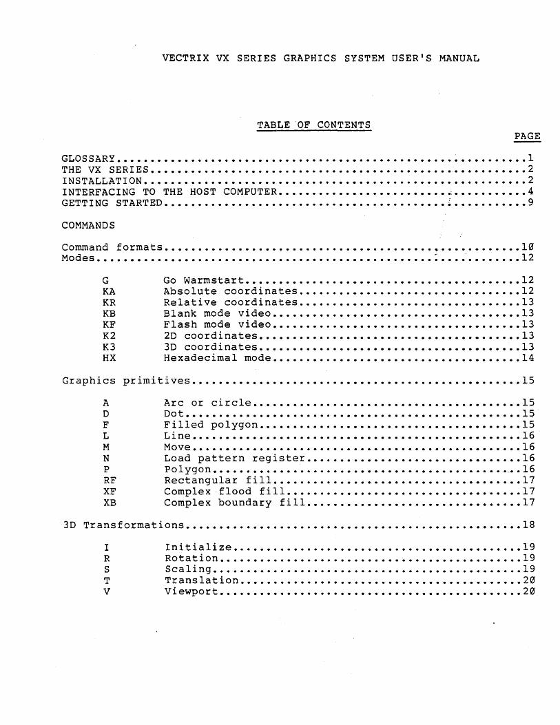
VECTRIX VX SERIES GRAPHICS SYSTEM USER'S MANUAL
TABLE 'OF CONTENTS
GLOSSARy •••••• THE VX SERIES. INSTALLATION •••• INTERFACING TO THE HOST COMPUTER. GETTING
COMMANDS
Command Modes •••
G KA KR KB KF K2 K3 HX
STARTED ••••••••••••••••••
formats ••
Go Warmstart ••••••••••• Absolute coordinates. Relative coordinates •• Blank mode video. Flash mode video. 2D coordinates •••• 3D coordinates ••••• Hexadecimal mode ••
PAGE
• . . • . . • . 1 • • 2
• • • • • • • • • • • 2 . . . . . ••• 0: . . . .. .
· . . . . . . . ... .
.4
.9
.10
.12
.12
.12
.13
.13 • •• 13
.13 • .13
.14
Graphics primitives •• ........•....••....•...•...•...••.•... . 15
A Arc or circle •• . . . . . . .15 D Dot ••••••••••• . . . . . • .15 F Filled polygon •• . . . . . · . . . . . . . . . .15 L Line •••• . . . . . . . . . . • .16 M Move •• · . . . . . . • •• 16 N Load pattern register •• • .16 P Polygon •••••• . . . . . . .,. .16 RF Rectangular fill •••••• . . . . . .17 XF Complex flood fill ••••• . . . . . .17 XB Complex boundary fill. . . . . . •• 17
3D Transformations •••••••••••••••••••••••••••••••••••••••••••••••••• 18
I R S T V
Initialize •• Rotation •••• Scaling ••••• Translation ••• Viewport ••••
• .19 • •• 19 ..19
.20 ..20
/ \
\
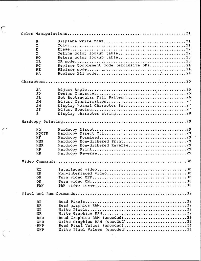
Color Manipulations ••••••••••••••••••••••••••••••••• ~ ••••••••••••••• 21
B C E Q RQ OR RC RE RA
Characters ••••
JA JD JR JM IN JS $
Bitplane Color •••
write mask.
Erase ••• Define color Return color OR mode ••••••
lookup table •• lookup table.
Replace REplace Replace
Complement mode •••••• All mode ••
mode (exclusive ...
. . .
OR)
.21 • .21
• •• 22 .22
• •• 23 .23
• •• 24 ••• 24
.24
. . . . . . . . . . . . . . . . . . . . . . . . . . . . . . . . . . . . . . . . . . . . . . .•••..• . 25
Adjust Ang le •••••••••• . . . . ~. . . . . . .25 Design Character ••••• . . . . . .25 Set Rectangular Fill Pattern •• • •• 26 Adjust Magnification ••••• · . . . . . . . . . . . ••• 27 Display Normal Character Set •• . . . . . ••• 27 Adjust Spacing •••• . . . . . . . . . . . . . • ••• 27 Display character string. · . . . . . . . . . . . . . . . . .28
Hardcopy Printing •••••••••••••• · .•••••.•...••..••...•.•••• • 29
HD Hardcopy Direct. . . . . . .29 HDOFF Hardcopy Direct Off •• • •• 29 . . . . . HF Hardcopy Formfeed ••• .29 HNP Hardcopy Non-dithered Print •• • •• 29 HNR Hardcopy Non-dithered Reverse. . . . . . ••• 29 HP Hardcopy Print •••• · . . . . . . . . . . .29 HR Hardcopy Reverse. •• 29
Video Commands ••••••••••• •...........•••......••.•••••..•..• • 30
KI Interlaced video. . . . . . .30 KN Non-interlaced video. . . . . . ..30 OF Turn video OFF •• · . . . . . . . . . • •• 30 ON Turn video ON •• ••• 30 PAN PAN video image •• . . . . . .30
Pixel and Ram Commands ••••• • . • • . • • • . . • • • • • • • • . . . . . • . • • • • • • • • 32
RP Read Pixels. . . . . . . • •••• 32 RR Read graphics RAM •• . . . . . .32 WP Write pixels ••••••• . . . . . . . . . . . ••• 32 WR Write Graphics RAM •• ••• 32 RNR Read Graphics RAM (encoded) ••• 33 WNR write Graphics RAM (encoded) •••• • 33
-RNP Read Pixel Values (encoded). ••• 34 WNP Write Pixel Values (encoded) .34
Miscellaneous
K128 RV U WF
Commands ••••••••••••••••••••••••••••••••••••••••••••••• 35
Emula te VX128 Mode •••••••••••••••••••••••••••• · •••••••• 35 Return Version number ••••••••••••••••••••••••••••••••• 35 Upload and execute user code •••••••••••••••••••••••••• 35 Wait Frames ••••••••••••••••••••••••••••••••••••••••••• 35
T u tor i a 1 • • • • • • • • • • • • • • • • • • • • • • • • • • • • • • • • • • • • • • • • • • • • • • • • • • • .~ • • • • • • • • • 36
Terminal Commands ••••••••••••••••••••••••••••••••••••••••• • r •••••••••• 41
Terminal Characteristics ••••••••••••••••••••••••••••••••• ~ ••••••••••• 42
Control Codes •••••••••••••••••••••••••••••••••••••••••••••••. : •••••••• 43
Escape Command Sequences ••••••••••••••••••••••••••••••••••••••••••••• 43
warning: This equipment generates, uses, and can radiate radio frequency energy and if not installed and used in accordance with the instruction manual, may cause interference to radio communications. It has been teste~ and found to comply with the limits for a Class A computing device pursuant to Subpart J of Part 15 of FCC Rules, which are designed to provide reasonable protection against such interference when operated in a commercial environment. Operation of this equipment in a residential area is likely to cause interference, in which case the user at his own expense will be required to take whatever measures may be required to correct the interference.
GLOSSARY OF TERMS
Current drawing point: Imagine an invisible cursor located wherever the last command stopped drawing.
Pixel: Short for "picture element," meaning an individual dot on the screen. The VX has 672 pixels horizonta·lly and 480 vertically.
RGB: Red, green, blue referring to the use of three separate color Slgnals for finer color differentiation than is possible with the standard "NTSC" TV system.
V{ewport: The area of the display screen you choose for displaying images. (For 3D mode only.)
-1-
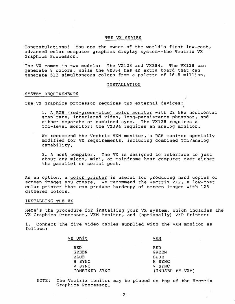
THE VX SERIES
Congratulations! You are the owner of the world's first low-cost, advanced color computer graphics display system--the Vectrix VX Graphics Processor.
The VX comes in two models: The VX128 and VX384. The VX128 can generate 8 colors, while the VX384 has an extra board that can generate 512 simultaneous colors from a palette of 16.8 million.
INSTALLATION
SYSTEM REQUIREMENTS
The VX graphics processor requires two external devices:'
1. 'A RGB (red-green-blue) color monitor with 22 kHz horizontal scan rate, interlaced video, long-persistence phosphor, and either separate or combined sync. The VX128 requires a TTL-level monitor; the VX384 requires an analog monitor.
We recommend the Vectrix VXM monitor, a RGB monitor specially modified for VX requirements, including combined TTL/analog capability.
2. A host computer. The VX is designed to interface to just about any micro, mini, or mainframe host computer over either the parallel or serial port.
As an option, a color printer is useful for producing hard copies of screen images you create. We recommend the Vectrix VXP, a low-cost color printer that can produce hardcopy of screen images with 125 dithered colors.
INSTALLING THE VX
Here's the procedure for installing your VX system, which includes the VX Graphics Processor, VXM Monitor, and (optionally) VXP Printer:
1. Connect the five video cables supplied with the VXM monitor as follows:
VX Unit
RED GREEN BLUE H SYNC V SYNC COMBINED SYNC
VXM
RED GREEN BLUE H SYNC V SYNC (UNUSED BY VXM)
NOTE: The Vectrix monitor may be placed on top of the Vectrix Graphics Processor.
-2-
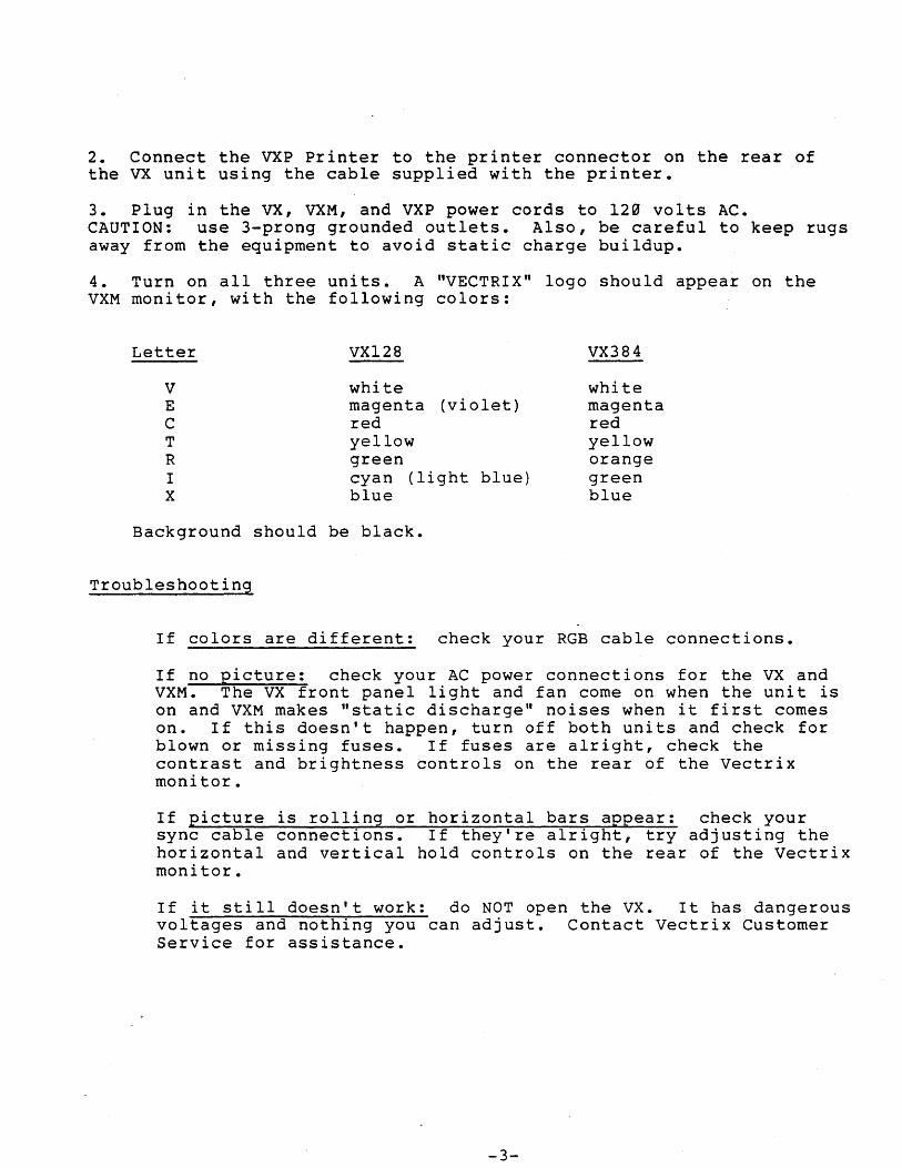
2. Connect the VXP Printer to the printer connector on the rear of the VX unit using the cable supplied with the printer.
3. Plug in the VX, VXM, and VXP power cords to 120 volts AC. CAUTION: use 3-prong grounded outlets. Also, be careful to keep rugs away from the equipment to avoid static charge buildup.
4. Turn on all three units. A "VECTRIX" logo should appear on the VXM monitor, with the following colors:
Letter VX128 VX384
V white white E magenta (violet) magenta C red red T yellow yellow R green orange I cyan (light blue) green X blue blue
Background should be black.
Troubleshooting
If colors are different: check your RGB cable connections.
If no picture: check your AC power connections for the VX and VXM. The VX front panel light and fan come on when the unit is on and VXM makes "static discharge" noises when it first comes on. If this doesn't happen, turn off both units and check for blown or missing fuses. If fuses are alright, check the contrast and brightness controls on the rear of the Vectrix monitor.
If picture is rolling or horizontal bars appear: check your sync cable connections. If they're alright, try adjusting the horizontal and vertical hold controls on the rear of the Vectrix monitor.
If it still doesn't work: do NOT open the VX. It has dangerous voltages and nothing you can adjust. Contact Vectrix Customer Service for assistance.
-3-
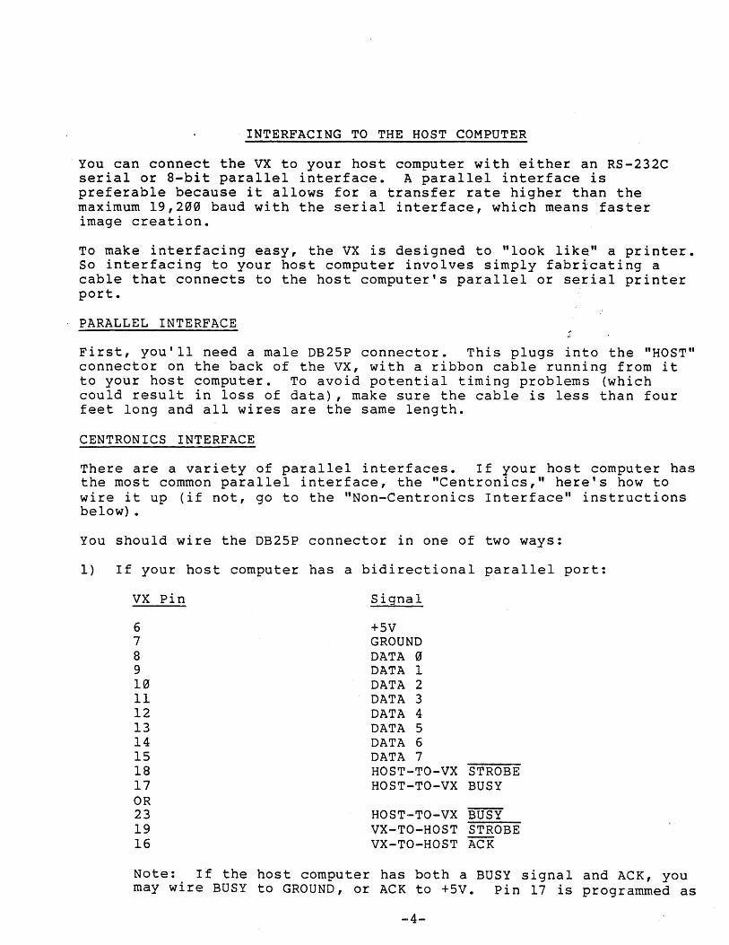
. INTERFACING TO THE HOST COMPUTER
. You can connect the vx to your host computer with either an RS-232C serial or 8-bit parallel interface. A parallel interface is preferable because it allows for a transfer rate higher than the maximum 19,2~~ baud with the serial interface, which means faster image creation.
To make interfacing easy, the VX is designed to "look like" a printer. So interfacing to your host computer involves simply fabricating a cable that connects to the host computer's parallel or serial printer port.
PARALLEL INTERFACE
First, you'll need a male DB25P connector. This plugs into the "HOST" connector on the back of the VX, with a ribbon cable running from it to your host computer. To avoid potential timing problems (which could result in loss of data), make sure the cable is less than four feet long and all wires are the same length.
CENTRONICS INTERFACE
There are a variety of parallel interfaces. If your host computer has the most common parallel interface, the "Centronics," here's how to wire it up (if not, go to the "Non-Centronics Interface" instructions below) •
You should wire the DB25P connector in one of two ways:
1) If your host computer has a bidirectional parallel port:
VX Pin Signal
6 +5V 7 GROUND 8 DATA ~ 9 DATA 1 10 DATA 2 11 DATA 3 12 DATA 4 13 DATA 5 14 DATA 6 15 DATA 7 18 HOST-TO-VX STROBE 17 HOST-TO-VX BUSY OR 23 HOST-TO-VX BUSY 19 VX-TO-HOST STROBE 16 VX-TO-HOST ACK
Note: If the host computer has both a BUSY signal and ACK, you may wire BUSY to GROUND, or ACK to +5V. Pin 17 is programmed as
-4-
a BUSY signal with its complement on pin 23. If your host requires an ACK, the ACKmust come from the trailing edge BUSY.
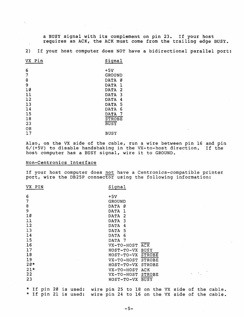
2) If your host computer does NOT have a bidirectional parallel port:
VX Pin Signal
6 +5V 7 GROUND 8 DATA 0 9 DATA 1 10 DATA 2 11 DATA 3 12 DATA 4 13 DATA 5 14 DATA 6 15 DATA 7 18 STROBE 23 BUSY OR 17 BUSY
Also, on the VX side of the cable, run a wire between pin 16 and pin 6/(+5V) to disable handshaking in the VX-to-host direction. If the host computer has a BUSY signal, wire it to GROUND.
Non-Centronics Interface
If your host computer does not have a Centronics-compatible printer port, wire the DB25P connector using the following information:
VX PIN
6 7 8 9 10 11 12 13 14 15 16 17 18 19 20* 21* 22 23
* If pin 20 is used: * If pin 21 is used:
Signal
+5V GROUND DATA 0 DATA 1 DATA 2 DATA 3 DATA 4 DATA 5 DATA 6 DATA 7 VX-TO-HOST ACK HOST-TO-VX BUSY HOST-TO-VX STROBE VX-TO-HOST STROBE HOST-TO-VX STROBE VX-TO-HOST ACK VX-TO-HOST STROBE HOST-TO-VX BUSY
wire pin 25 to 18 on the vx side of the cable. wire pin 24 to 16 on the VX side of the cable.
-5-
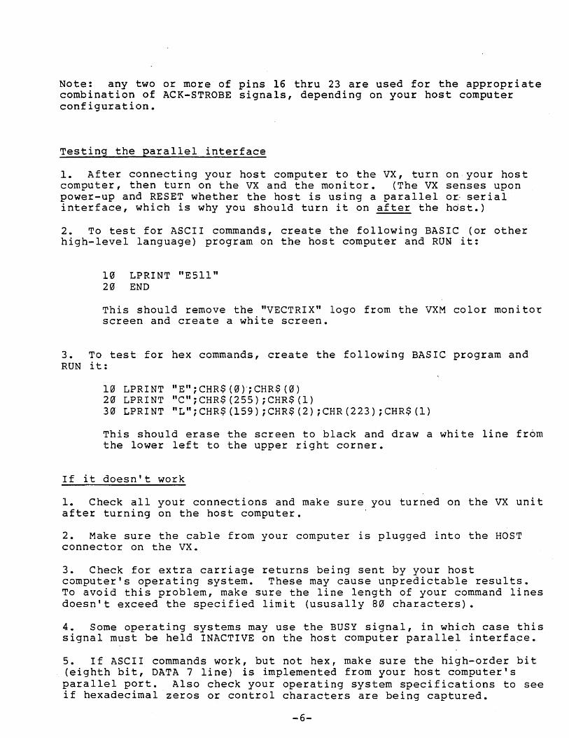
Note: any two or more of pins 16 thru 23 are used for the appropriate combination of ACK-STROBE signals, depending on your host computer configuration.
Testing the parallel interface
1. After connecting your host computer to the VX, turn on your host computer, then turn on the VX and the monitor. (The VX senses upon power-up and RESET whether the host is using a parallel o~ serial interface, which is why you should turn it on after the hd~t.)
2. To test for ASCII commands, create the following BASIC (or other high-level language) program on the host computer and RUN it:
10 LPRINT "E5ll" 20 END
This should remove the "VECTRIX" logo from the VXM color monitor screen and create a white screen.
3. To test for hex commands, create the following BASIC program and RUN it:
10 LPRINT liE" ;CHR$ (0)';CHR$ (0) 20 LPRINT "C";CHR$(255);CHR$(1) 30 LPRINT "L";CHR$(159);CHR$(2);CHR(223);CHR$(l)
This should erase the screen to black and draw a white line from the lower left to the upper right corner.
If it doesn't work
1. Check all your connections and make sure you turned on the VX unit after turning on the host computer.
2. Make sure the cable from your computer is plugged into the HOST connector on the VX.
3. Check for extra carriage returns being sent by your host computer's operating system. These may cause unpredictable results. To avoid this problem, make sure the line length of your command lines doesn't exceed the specified limit (ususally 80 characters).
4. Some operating systems may use the BUSY signal, in which case this signal must be held INACTIVE on the host computer parallel interfa~e.
5. If ASCII commands work, but not hex, make sure the high-order bit (eighth bit, DATA 7 line) is implemented from your host computer's parallel port. Also check your operating system specifications to see if hexadecimal zeros or control characters are being captured.
-6-
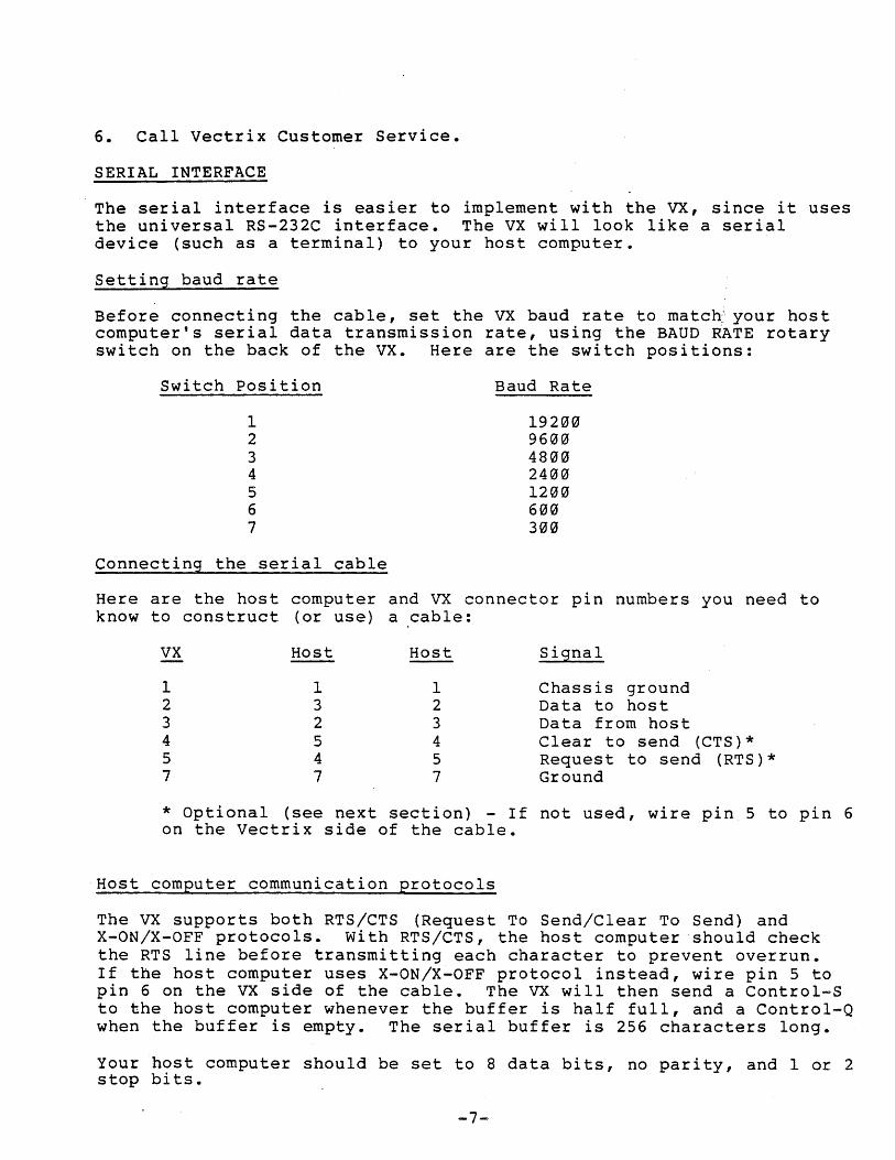
6. Call Vectrix Customer Service.
SERIAL INTERFACE
. The serial interface is easier to implement with the VX, since it uses the universal RS-232C interface. The VX will look like a serial device (such as a terminal) to your host computer.
Setting baud rate
Before connecting the cable, set the VX baud rate to matc~your host computer's serial data transmission rate, using the BAUD RATE rotary switch on the back of the VX. Here are the switch positions:
Switch position
1 2 3 4 5 6 7
Connecting the serial cable
Baud Rate
19200 9600 4800 2400 1200 600 300
Here are the host computer and VX connector pin numbers you need to know to construct (or use) a cable:
VX Host
1 1 2 3 3 2 4 5 5 4 7 7
Host
1 2 3 4 5 7
Signal
Chassis ground Data to host Data from host Clear to send (CTS)* Request to send (RTS)* Ground
* Optional (see next section) - If not used, wire pin 5 to pin 6 on the Vectrix side of the cable.
Host computer communication protocols
The VX supports both RTS/CTS (Request To Send/Clear To Send) and X-ON/X-OFF protocols. with RTS/CTS, the host computer should check the RTS line before transmitting each character to prevent overrun. If the host computer uses X-ON/X-OFF protocol instead, wire pin 5 to pin 6 on the VX side of the cable. The VX will then send a Control-S to the host computer whenever the buffer is half full, and a Control-Q when the buffer is empty. The serial buffer is 256 characters long.
Your host computer should be set to 8 data bits, no parity, and 1 or 2 stop bits.
-7-
Testing the serial interface
You can test the serial interface the same way as described above ("Testing the Parallel Interface"). If that doesn't work, try switching the wires to pins 2 and 3 and pins 4 and 5 on the host side of the cable.
-8-
GETTING STARTED
PROGRAMMING
The VX looks like a printer to your host computer, so the easiest way to send it a command is to simply create a BASIC (or any other high-level language) program with a "print" statement.
For example, in BASIC, run this program:
10 LPRINT "E0" (zero, not the letter "0" and upper .. :·case letter E)
That should erase the Vectrix logo from the screen and set the screen color to black. And this •••
10 LPRINT "C5ll" 20 LPRINT "0 250 350"
generates a white dot at screen position (250,350).
Or if you want something easier to use, try this:
10 DIM A$(80) 20 INPUT A$ 30 LPRINT A$ 40 GOTO 20
Just type a command (without quote marks) after the "?" mark generated on each line by your computer.
You can put more than one command on the same line, but if your BASIC automatically sends a carriage return -- for example, after 80 characters -- make sure you keep line length less than 80 characters.
Here are a few suggested things to try:
E0 Erases the screen to black. L 300 300 Draws a line to location (300,300)
-9-
COMMAND FORMATS
VX commands consist of two parts: one or more letters (must be upper case) followed by numeric arguments, shown in this manual in lower case.
ASCII or Hex
You can express numeric arguments in either ASCII (decimal) or hexadecimal (hex) formats. The VX automatically expects ASCII arguments when you first turn the unit on. Whenever you send a B, C, E, or Q command, the VX will interpret arguments in all future commands as being in the same format used (ASCII or hex) until the next B, C, E, or Q command. Whenever you press RESET or send a G command, the VX resets back to ASCII format, whereas the HX command automatically places the Vectrix in hexadecimal mode. t
Word Values
Based on the number of digits required, each command uses either "word" or "byte" values for the number. We'll tell you which is required for each command. We define word values as decimal (ASCII) numbers from 0 to 65535 for counts, and from -32767 to +32767 for coordinates (OK to use the "_" sign; the "+" sign is not necessary, of course -- but don't put in a comma to separate thousands). If you're using hex numbers, you should send them as two-byte (16-bit) signed integers ranging from 0000 to FFFF or 8001 to 7FFF, with low byte
. (LSB) first, high byte (MSB) second -- using two's complement notation for negative numbers.
When word values are returned to the host computer (for instance by the Read Pixel and RAM commands), they are returned in the current transmission format (ASCII or hexadecimal). If in ASCII mode, word values are returned as a fixed length string of five ASCII digits ("00000" through "65535") with leading zeros, and followed by a carriage return (no linefeed).
Byte values
We define byte values as decimal (ASCII) unsigned numbers from 0 to 255 or hex numbers from 0 to FF.
When byte values are returned to the host computer (for instance by the RQ command), they are returned in the current transmission format (ASCII or hexadecimal). If in ASCII mode, byte values are returned as a fixed length string of three ASCII digits ("000" through "255") with leading zeros, and followed by a carriage return (no linefeed).
Delimiters
When you enter a command in ASCII mode, you must use one or more delimiters between numeric arguments. Valid delimiters are commas, spaces, or carriage returns (with or without linefeeds). In hex mode, delimiters are not required, and in fact, are not allowed. Note: if
-10-
you are using INPUT mode in BASIC, commas are not allowed in an input line for string data in BASIC.
You can concatenate commands (put more than one on the same line) up to the line length of the operating system or language you are using. Spaces, commas, carriage returns, and other valid delimiters may be used to separate commands, however, these delimiters are all optional.
Screen layout
The vx screen is laid out as a rectangle, with 672 pixels ~orizontally and 480 pixels vertically: (O,O) is the lower left corner ,.: and (671,479) is the upper right corner of the screen. The center of the screen is (336,240).
Version number
If a version number is indicated after a command, this indicates the revision of the PROMs in which the command was implemented. To determine what version of the PROMs are installed in a particular vectrix unit use the "RV n command.
-11-
MODES
The VX operates in three basic modes. You can choose absolute or relative coordinates, blank or flash drawing, 2D or 3D, and ASCII or hexadecimal transmission. There are also several modes dealing with color combination (see "Color Manipulations" section) and video interlace format.
1. Go Warmstart
Format: G
The G command executes a warmstart initialization of the Vectrx unit, resetting the internal operating modes: to a known state. The G command:
(1) (2) (3) (4 ) (5 ) (6) (7 ) (8 ) (9)
'" (10)
(11 ) (12 ) (13) (14) (15 )
sets to ASCII format sets to absolute coordinates sets to 20 coordinates sets to OR mode resets the viewport .to full screen sets the 3-D transformation matrix to identity resets the character set to the default set sets the pattern register to a solid line reinitializes to the default color lookup table resets character magnification, angle, and spacing resets the current drawing point to (0,0,0) resets the bitplane mask register to all ones initializes the 8088 stack register resets image pan to zero resets the rectangular fill pattern to all ones
Except for possibly changing the color lookup table, the G command does not affect the screen display. The action of the G command is the same as pressing the RESET switch, except that the RESET switch also determines whether the parallel or serial interface is connected from the host computer.
2. Absolute vs. relative
KA Absolute coordinates
Format: KA
In absolute mode, coordinates x,y or x,y,z for all subsequent commands are referenced to the origin (0,0) which is at the bottom left corner of the screen in 2D mode. In 3D mode, coordi~ates are referenced to (0,0,0) (center of viewport). (Default mode).
-12-
KR Relative coordinates
Format: KR
In relative mode, all subsequent x,y or x,y,z values you enter are interpreted as relative to the current drawing point (rather than the origin, as in absolute mode). Relative mode is preferable when defining an object for multiple display on the screen or when expressing coordinates as lengths (delta-x, delta-y, and delta-z) rather than as absolute coordinates.
3. Blank vs. flash
KB Blank mode video
Format: KB
You should use blank mode when you want to avoid flash mode streaks in an image while it's being changed. Since the display is updated only during retrace periods, the image is not interfered with. However, update speed is approximately 25% as fast as it.is in flash mode. (Default mode).
KF Flash mode video
Format: KF
In flash mode, the screen is continually updated (rather than only during retrace periods), so update is faster. However, the screen may flash short horizontal streaks as it changes the image.
4. 2D vs. 3D
K2 2D coordinates
Format: K2
In 2D mode, coordinates are positive integers referenced to the origin (0,0) which is at the lower left hand corner of the screen. Clipping is not performed in 2D mode, so lines that extend beyond the screen boundaries will wraparound into subsequent bitplanes. (Default mode).
Coordinates in 2D mode can range from 0 to 671 in the x-axis and 0 to 479 in the y-axis.
K3 3D ~oordinates
Format: K3
In 3D mode, you specify x, y, and z coordinates for Dot, Line,
-13-
Move, Polygon, and Filled Polygon commands. Coordinates are referenced to the object-space origin (3,3,3), which is the center of the,viewport, rather than the lower-left corner screen origin (3,0), as in 20. The z coordinate represents the apparent distance of the object from the observer in 3D vanishing perspective.
In 3D mode, points outside the viewport are clipped (made invisible).
Coordinates in 3D mode can range from -32767 to +32767.
Y~u can freely mix objects drawn in 20 and 3D modes.
s. ASCII vs. Hexadecimal
HX Hexadecimal Mode (VI.S)
Format: HX
When powered on the Vectrix defaults to ASCII transmission format, accepting numeric arguments as ASCII strings separated by various delimiters. Whenever you send a B, C, E, or Q command, the VX will interpret arguments in all future commands as being in the same format used in these. four commands (ASCII or hex) until the next B, C, E, or Q command. Whenever you press RESET or send a G command, the VX resets back to ASCII format, whereas the HX command automatically places the Vectrix in hexadecimal mode.
-14-
GRAPHICS PRIMITIVES
The VX lets you create just about any conceivable image with various combinations of graphics primitives (basi~ geometric forms -- dots, lines, arcs, and polygons).
The VX will draw the image in the color you have specified in the Color command (white is the default color when you first turn the unit on), using a pattern you have specified in the Define Pattern N command (or the default pattern: solid line).
A ARC OR CIRCLE
D DOT
Format: A radius angles anglea
Draws an arc with a center at the current drawing point and radius ("radius") as specified (in pixels). The arc starts at the start angle ("angles") and sweeps through the arc angle ("angle a "). Both angles are in tenths of a degree (so you would, tor example, enter 90 degrees as "900"). Angles is referenced to the +x axis (the horizontal). For both angles, positive yalues go counterclockwise and negative values go clockwise. The current drawing point remains at the center of the arc after the arc command is executed. (radius, angles' and anglea are word values).
Note: to draw a circle, use anglea = 3600
Format: D x y z
Draws a dot at screen location (x,y) or if in 3D mode at (x,y,z). (x, y, and z are word values).
F FILLED POLYGON
Format: F color count xl YI zl x2 Y2 z2···
Draws a polygon with "count" number of vertices at the specified (x,y) or if in 3D mode (x,y,z) coordinates. Vertices may be specified either in clockwise or counterclockwise order. The polygon also automatically fills with the interior color you specify in the "color" argument. The boundary is drawn in the current drawing color, as set previously by the C command. (color, count, x, y, and z are word values).
Note: Unlike the P command, this command is limited to 256 sets of vertices. Another limitation is that the VX fill algorithm is a "y scan line convex polygon fill" and does not fill polygons with concave (squeezed in) areas on the top or bottom of the polygon.
-15-
L LINE
Format: L x y z
In 2D mode, draws a line from the current drawing point to (x,y) on the screen. In 3D mode, draws a line to (x,y,z) in object space. (x, y, and z are word values).
M MOVE
Format: M x y z
The current drawing point moves to a new (x,y) position on the screen without drawing any lines on the display, thus defining a new current drawing point. In 3D mode: the current drawing point moves in object-space coordinates (x,y,z). ~(x, y, and z are word values). ~
N LOAD PATTERN REGISTER
Format: N pattern
This command will let you get creative, and design dot and dash-type line patterns or "textured" filled polygon patterns. "Pattern" is a number whose 16-bit binary equivalent represents the dot-dash pattern (1 = dot on, ~ = dot off). This command may be used when drawing lines, arcs, polygons, and filled polygons. (pattern is a word value).
You design the pattern in three steps:
1. Draw the pattern you want on paper as a series of 16 cells, each on or off.
2. write down the binary equivalent
3. Convert this binary number into its decimal (ASCII) or hex equivalent and enter it into the command as the "pattern".
The default pattern value is 65,535 ASCII (or FFFF hex), corresponding to all binary l's (a solid line). You can use this number to reset the pattern to a solid line. Another good number to know is 21845 (5555H hex), which creates a pattern of dots.
P POLYGON
Format: P count Xl Yl zl x2 Y2 z2···
Draws a polygon with vertices at (x,y) or if in 3D mode at (x,y,z) and automatically closes the polygon (so you don't have to enter the beginning coordinates again). vertices may be specified either in clockwise or counterclockwise order. (count, x, y, and z are word values).
-16-
RF RECTANGULAR FILL (Vl.3)
Format: RF width height
This is a fast way to draw a filled rectangle (four times faster than the F command). Starting at the current drawing point, a filled rectangle is drawn. If width and height are positive, then the current drawing point is the lower left corner of the rectangular area filled. However, width and/or height may be negative, in which case the current drawing point is the right and/or upper corner of the area, respectively. The ~ectangle is filled using the 8 x 8 pattern defined by the JR com~and. Entering into terminal mode and the G command reset the rectangular fill pattern to all ones.
The current drawing point is not moved by the RF command. Remember that, unlike performing a filled polygon 1n relative mode, width and height are equal to deltax + I and deltay + 1, respectively. (width and height are word values).
XF COMPLEX FLOOD FILL (VI.S)
Format: XF
Fills the region containing the same color as the current drawing point with the current color. This command performs its drawing in replace mode. Sending a control-E (hexadecimal 05) to the VX unit while the XF command is executing will abort the fill. The pattern register is ignored during fills. The edges of the screen are considered fill boundaries.
XB COMPLEX BOUNDARY FILL (Vl.S)
Format: XB boundary-color
Fills the region containing the current drawing point and bounded by boundary-color with the current color. This command performs its drawing in replace mode. Sending a control-E (hexadecimal 05) to the VX unit while the XB command is executing will abort the fill. The pattern register is ignored during fills. The edges of the screen are considered fill boundaries. (boundary-color is a word value).
-17-

3D TRANSFORMATIONS
You can use the 3D transformation commands to rotate, scale (magnify), and translate (move in x, y, or z planes) an object, or set the viewport (viewing window on the screen). No knowledge of matrix algebra is required -- these calculations are done automatically by the vx.
In 3D mode, the drawing coordinates sent to the Vectrix do not represent screen coordinates, but object space coordinates~ These can range from -32,767 to +32,767 along all three dimensions. ; The Vectrix automatically transforms the three dimensional images into two dimensional screen coordinates using 3D vanishing perspective and clipping within the active viewport. .
The Vectrix provides several commands that cause the object coordinates of subsequent commands to be transformed in various ways. The three major transformations provided are rotation, translation, and scaling.
In 3D mode, the eye position is always at object location (0,0,0) which is mapped to the center of the viewport. The Vectrix automatically performs clipping as follows:
(1) All points with z coordinates <= 0 are clipped as being behind the eye position (near-plane clipping). No far-plane clipping is performed along the z axis; lines are allowed to extend to infinity.
(2) The screen is clipped against the viewing pyramid, which is defined by the four planes: x = +z, x = -z, y = +z, y = -z.
There are two techniques for creating a square aspect ratio: (1) by using a square viewport, or (2) by using a scale factor as the final step before perspective scaling (see the Viewport command).
Perspective views on the vectrix require that the user perform the perspective transformation as the very final step in the transformation process before beginning to draw. The perspective transformation is performed by scaling the x and y axes each by the ratio D/S, where 0 is the distance along the z axis from the eye point to the desired display screen and S is the size of the display screen. If the ratio of D/S is small, the perspective will be similar to an image viewed through a wide angle lens. If the ratio of D/S is large, the perspective will be similar to an image viewed through a telephoto lens.
These commands are only active when you have selected 3D mode (K3 command) •
-18-
I INITIALIZE
Format: I
Initializes the image transformation matrix (cancels previous rotation, scaling, and translation commands). This command is also automatically performed when you first turn on the VX, when you press the RESET switch, or transmit a G command.
R ROTATION
Format: RX angle RY angle RZ angle
Rotates subsequently-entered lines by signed "angle" (in tenths of a degree) in x, y, or z planes around the object-space origin (O,O,O). To rotate an object around its own center: translate it to the origin, rotate it, and translate it back. (angle is a word value).
S SCALING
Format: SX multiply-factor SY multiply-factor SZ multiply-factor
divide-factor divide-factor divide-factor
Scales subsequently-entered lines in x, y, and z axes with reference to the object-space origin (O,O,O), based on signed multiply and divide factors.
Two (signed) integers are used to provide a full range of factors. A negative scale factor will provide a mirror image around an axis. Note, that only one of the factors should be negative to specify mirror image scaling; a negative number divided by a negative is positive. The positive z axis is defined as going "into" the screen, so a z scaling ratio greater than one moves an object farther away from the viewer, and thus it appears smaller on the screen.
The vectrix does not allow a divide by zero error. If zero is given as the divide factor, a value of one is used.
To scale an object around its own center: translate it to the origin, scale it, and translate it back. (multiply-factor and divide-factor are word values).
-19-
T TRANSLATION
Format: TX x TY Y TZ z
Translates subsequently-entered lines along the x, y, or z axis by the signed (positive or negative) x, y, or z distance specified. The positive z axis is defined as going ~into" the screen, so positive z values move an object farther away from the viewer, while negative z values move it closer. (x, y, and z are word values).
V VIEWPORT
Format: V xl xr Yb Yt
Sets the active region of the screen for 3D drawing, defined in screen coordinates, as follows: xl = left side; xr = right side; Yb = bottom;Yt = top (all word values).
Attempting to draw lines outside the viewport will result in the line being clipped to display only its visible segments, if any.
Default: full screen (V 0 671 0 479).
These are the maximum legal values for the viewport. Settin~ it to larger values causes lines exceeding the screen area wrapping around into successive bitplanes. The viewport is operative only in 3D mode. Setting a viewport in 2D mode will not result in clipping.
There are two techniques for creating a square aspect ratio: (1) by using a square viewport, such as:
V 96,575,0,479 or (2) by using a scale factor of 480 divided by 672 as the final step before perspective scaling:
SX 480,672.
-2~-
COLOR MANIPULATIONS
The color manipulation commands allow you to precisely control the color of images and background as well as achieve a variety of animation and color-combination effects.
The VX divides its memory up into "bitplanes." 670 x 480 bits (pixels) on the screen. On the bitplanes, allowing for 8 colors on the screen the VX384, there are 9 bitplanes, allowing for simultaneously.
B BITPLANE WRITE MASK
Format: B bitplane-mask-register
Each bitplane stores VX128, there are j simultBneoU~lY (2 ); on 512 (2 ) colors
The B command enables which bitplanes may be written to. The B command lets you perform animation and other effects. It does this by defining which bitplanes are enabled for update, based on the binary equivalent (VX128: 3-bit; VX384: 9-bit) of the value of mask-register (bitplane-mask-register is a word value) •.
For example, binary 100 represents the third bitplane enabled for update ("1") and all others not enabled ("0"). So you would transmit a "B 8" command (binary 100 = 8).
You can create animation effects on the VX384 by storing several images -- each in different planes using the B command -- and switching between them, using the color lookup table (Q command). You can also use a bitplane to store text that can be displayed on the screen independently of graphics images (as is done in terminal mode).
C COLOR
Format: C color
This command sets the current drawing color. This command changes the color of all subsequently drawn graphics objects and characters.
On the VX128, color numbers can range form 0 to 7; on the VX384, from 0 to 511 (color is a word value on both).
-21-
Common.ly-used color numbers are:
Color VX128 VX384 Color VX128 VX384 Black 0 ° Blue 4 448 Red 1 7 Magenta 5 455 Green 2 56 Cyan 6 504 Yellow 3 63 White 7 511
The VX determines if transmissions are in ASCII or hex mode from the format of the "color" argument in the B, C, E, and Q commands.
E ERASE
Format: E color
Erases the screen, setting background screen color to "color" (see C command) and current drawing point to (0,O) or (0,O,O). (color is a word value).
The VX determines if transmissions are in ASCII or hex mode from the format of the "color" argument in the B, C, E, and Q commands.
If the default color lookup table is in effect (see Q command), "EO" clears the screen to black. On the VXl28, "E7" clears the screen to white; on the VX384, "E511" clears the screen to white.
The Erase command performs in flash mode when the bitplane mask register is all ones. If the bitplane mask register is not all ones, erase is performed in the current mode (flash or blank). Erasing performs significantly faster in flash mode.
Q DEFINE COLOR LOOKUP TABLE (VX384 only)
Format: Q rows count rl gl b1 r 2 g2 b 2 •••
This command works with the VX384 only. You can use this command to redefine any entries in the color lookup table, which is a table that defines RGB color saturation values for each of the 512 colors. This allows you to create your own unique palette of 512 colors (for example a grayscale).
Starting with "rows" and continuing for "count" rows, each row (corresponding to a color number) in the table can have 255 different values of saturation (O = no color, 255 = full saturation) of red, green, and blue, which is over 16 million possible colors! While the eye-cannot distinguish all of these colors, they are very useful for creating subtle shading effects. (row and count are word values; £, ~, and b are byte values) •
-22-
The default color lookup table (what you get when you turn on the unit) gives you a set of 512 colors distributed through the range of hues and saturations (lower 3 bits: increasing red; middle 3 bits: increasing green; upper 3 bits: increasing blue). Location 511 contains 255,255,255 and each decrement in red, green, or blue is by an amount of 32. Location 0 (which should therefore have 31,31,31) is loaded with 0,0,0 instead. The lookup table is linear and not gamma corrected.
This command performs in blank mode. 96 sets of RGBentries can be loaded in one vertical blanking interval, 256 set~ in three intervals, and all 512 in six vertical intervals. S~e the KI and KN command for video timing calculations.
RQ RETURN COLOR LOOKUP TABLE (VX384 ONLY) (VI.7)
Format: RQ rows count
This command works with the VX384 only. This command transmits to the host computer the RGB values of the color lookup table beginning with "rows" and continuing for "count" rows. R, G, and B are byte values and are returned in the current transmission format (hexadecimal or ASCII). This command currently performs in flash mode.
If in ASCII mode, the values are returned as a fixed length string of three ASCII digits ("000" through "255") with leading zeros, and followed by a carriage return (no linefeed).
OR OR MODE
Format: OR
The OR, RC, RE, and RA commands give you four ways to combine colors. When you're in OR mode, all subsequently-entered lines or dots will "or" (mix) with the old colors residing in the effected pixels. You can determine the exact new color number by looking at the binary equivalents of the color numbers for the pixel in question. The resulting binary number is the number you get when you "or" each bit of the two numbers (if either bit is a "1", the resulting bit is a "1"; if both bits are 0, the result is 0). The resulting binary number is the new color number.
(This is the default mode).
Example (VX384): let's look at mixing pure red (color number 7) and pure green (color number 56). The bitplanes would look like this:
-23-
RC
Blue Green Red
Red: 000 000 III
Green: 000 III 000
Result: 000 111 III (Yellow, 63)
REPLACE COMPLEMENT MODE (exclusive OR) (Vl.4)
Format: RC
For each pixel subsequently drawn the RC mode replaces the pixel's binary value (0 or 1) with its complementt(if it's 0, it becomes 1, and vice versa). All bitplanes that have been enabled for update (by the B command) are complemented, irrespective of the current drawing color. Therefore, in order to perform an exclusive OR of background zero to a particular color, set the bitplane mask register to the desired color.
This command is useful for displaying cursors or crosshairs, for example, because any operation done twice results in a return to the original image.
RE REPLACE MODE
Format: RE
In the replace mode, when writing over an existing image, the new color simply replaces the old one, without mixing. This mode is slower than OR mode, because all enabled bitplanes must be written in order to replace the color.
RA REPLACE ALL MODE (Vl.4)
Format: RA
Similar to replace mode, except that not only are the ones in the pattern register drawn, but also the zeros. However, unlike the RE command, all bitplanes that have been enabled for update by the B command are replaced, irrespective of the current drawing color.
This command is useful for drawing one character over another, when the background zeroes of the character description need to be drawn in order to completely erase the previously drawn character.
-24-
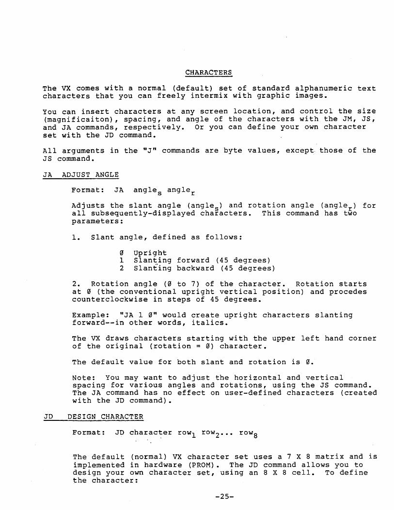
CHARACTERS
The vx comes with a normal (default) set of standard alphanumeric text characters that you can freely intermix with graphic images.
You can insert characters at any screen location, and control the size (magnificaiton), spacing, and angle of the characters with the JM, JS, and JA commands, respectively. Or you can define your own character set with the JD command.
All arguments in the "J" commands are byte values, except those of the JS command.
JA ADJUST ANGLE
Format: JA angles angler
Adjusts the slant angle (angles) and rotation angle (angler) for all subsequently-displayed characters. This command has two parameters:
1. Slant angle, defined as follows:
o Upright 1 Slanting forward (45 degrees) 2 Slanting backward (45 degrees)
2. Rotation angle (0 to 7) of the character. Rotation starts at 0 (the conventional upright vertical position) and procedes counterclockwise in steps of 45 degrees.
Example: "JA 1 0" would create upright characters slanting forward--in other words, italics.
The VX draws characters starting with the upper left hand corner of the original (rotation = 0) character.
The default value for both slant and rotation is 0.
Note: You may want to adjust the horizontal and vertical spacing for various angles and rotations, using the JS command. The JA command has no effect on user-defined characters (created with the JD command).
3D DESIGN CHARACTER
Format: JD character rowl row2 ••• rowa
The default (normal) VX character set uses a 7 X 8 matrix and is implemented in hardware (PROM). The 3D command allows you to design your own character set, using an 8 X 8 cell. To define the character:
-25-
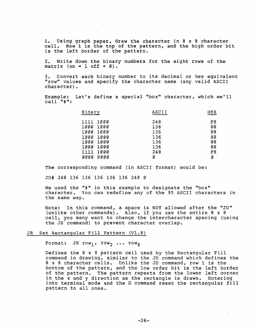
1. Using graph paper, draw the character in 8 x 8 character cell. Row 1 is the top of the pattern, and the high order bit is the left border of the pattern.
2. write down the binary numbers for the eight rows of the matrix (on = 1 off = 0).
3. Convert each binary number to its decimal or hex equivalent "row" values and specify the character name (any valid ASCII character) •
Example: Let's define a special "box" character, which we'll call "#":
Binary ASCII HEX
1111 1000 248 F8 1000 1000 136 88 1000 1000 136 88 1000 1000 136 88 1000 1000 136 88 1000 1000 136 88 1111 1000 248 F8 0000 0000 0 0
The corresponding command (in ASCII format) would be:
JD# 248 136 136 136 136 136 248 0
We used the "#" in this example to designate the "box" character. You can redefine any of the 95 ASCII characters in the same way.
Note: In this command, a space is NOT allowed after the "JD" (unlike other commands). Also, if you use the entire 8 x S cell, you many want to change the intercharacter spacing (using the JS command) to prevent character overlap.
JR Set Rectangular Fill Pattern (V1.S)
Format: JR rowl' row2 ••• rowS
Defines the S x 8 pattern cell used by the Rectangular Fill command in drawing, similar to the JD command which defines the 8 x 8 character cells. Unlike the JD command, row I is the bottom of the pattern, and the low order bit is the left border of the pattern. The pattern repeats from the lower left corner in the x and y direction as the rectangle is drawn. Entering into terminal mode and the G command reset the rectangular .fill pattern to all ones.
-26-
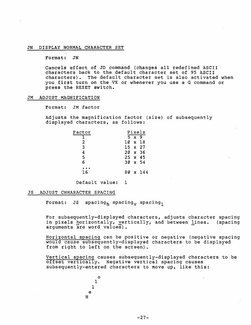
IN DISPLAY NORMAL CHARACTER SET
Format: IN
Cancels effect of JD command (changes all redefined ASCII characters back to the default character set of 95 ASCII characters). The default character set is also activated when you first turn on the VX or whenever you use a G command or press the RESET switch.
JM ADJUST MAGNIFICATION
Format: JM factor
Adjusts the magnification factor (size) of subsequently displayed characters, as follows:
Factor 1 2 3 4 5 6
16
Default value:
JS ADJUST CHHARACTER SPACING
Pixels 5 x 9
10 x 18 15 x 27 20 x 36 25 x 45 30 x 54
80 x 144
1
Format: JS spacingh spacingv spacing l
For subsequently-displayed characters, adjusts character spacing in pixels horizontally, vertically, and between lines. (spacing arguments are word values).
Horizontal spacing can be positive or negative (negative spacing would cause subsequently-displayed characters to be displayed from right to left on the screen).
Vertical spacing causes subsequently-displayed characters to be offset vertically. Negative vertical spacing causes subsequently-entered characters to move up, like this:
e H
o 1
1
-27-
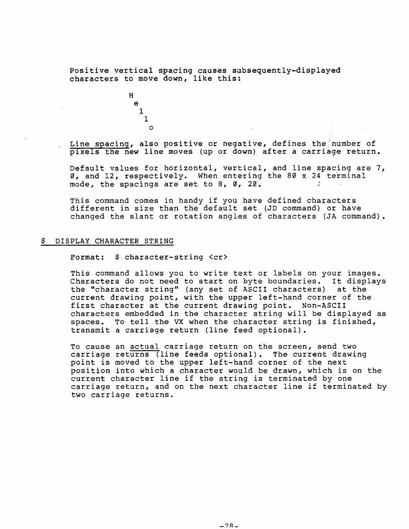
positive vertical spacing causes subsequently-displayed characters to move down, like this:
H e
I I
o
Line spacing, also pos i ti ve or negati ve, defines the .;~number of pixels the new line moves (up or down) after a carri~ge return.
Default values for horizontal, vertical, and line spacing are 7, 0, and 12, respectively. When entering the 80 x 24 te~minal mode, the spacings are set to 8, 0, 20. ~
This command comes in handy if you have defined characters different in size than the default set (JD command) or have changed the slant or rotation angles of characters (JA command).
$ DISPLAY CHARACTER STRING
Format: $ character-string <cr>
This command allows you to write text or labels on your images. Characters do not need to start on byte boundaries. It displays the "character string" (any set of ASCII characters) at the current drawing point, with the upper left-hand corner of the first character at the current drawing point. Non-ASCII characters embedded in the character string will be displayed as spaces. To tell the VX when the character string is finished, transmit a carriage return (line feed optional).
To cause an actual carriage return on the screen, send two carriage returns (line feeds optional). The current drawing point is moved to the upper left-hand corner of the next position into which a character would be drawn, which is on the current character line if the string is terminated by one carriage return, and on the next character line if terminated by two carriage returns.
HARDCOPY PRINTING
The VXP color printer allows you to get color hardcopy printouts of what's on your screen. You can also command the VXP to print out directly from the host computer.
HD Hardcopy Direct
Connects the host computer directly to the VXP color printer. This lets you use the printer for l~stings and other jobs without having to disconnect the ptinter from the VX.
To reconnect the host computer to the VX, pres~ the RESET switch, located behind the VX.
HDOFF <cr> Hardcopy Direct Off (Vl.S)
Turns off hardcopy direct mode. This command must be terminated by a carriage return.
HF Hardcopy Form Feed
Does a "form feed" on the VXP printer (advances one page) to allow you to tear off the printout.
HNP Hardcopy Non-dithered Print (Vl.7)
Prints an eight color representation of the screen image, matching screen colors to their closest print color counterparts, except for cyan, which prints as orange.
HNR Hardcopy Non-dithered Reverse (Vl.7)
Same as the HNP command, except that it prints the screen background color the reverse of what's displayed on the screen (black prints as white, and white as black). Can be used in order not to print large areas of black background on the paper.
HP Hardcopy Print
Prints a l2S color representation of the screen image using "dithering" (color - dot mixing), approximating screen colors to their closest print color combinations.
HR· Hardcopy Reverse
Same as .the HP command, except that it prints the screen background color as the reverse of what's displayed on the screen (black prints as white, and white as black). Can be used in order not to print large areas of black background on the paper.
-29-
VIDEO COMMANDS
KI INTERLACED VIDEO
Format: KI vfp vs vbp hfp hs hbp
The KI command draws two interlaced fields of video per frame (like a TV set). The parameters are vertical front ~porch (vfp) , vertical sync (vs), vertical back porch (vbp) , horizontal front porch (hfp) , horizontal sync (hs), and horizontal back porch (hbp) •
Horizont~l scan rate (HSR in kHz) = 1250/(42 + hfp + hs + hbp). vertical rate (in Hz) = (1000 * HSR)/(240 + vfp +~vs + vbp).
Horizontal values are in units of 800 nsec. vertical values are in number of scan lines. Default values are KI 2 6 16 5 5 5, which produces an interlaced image with a horizontal scan rate of 22 kHz and a vertical rate of 84 Hz. (all parameters are byte values). (Default mode).
KN NON-INTERLACED VIDEO
Format: KN vfp vs vbp hfp hs hbp
The KN command draws one complete field of video per frame.
Horizontal scan rate: same formula as KI command. vertical rate (in Hz) = (1000 * HSR)/(480 + vfp + vs + vbp).
Horizontal and vertical values are in the same units as the KI command.
OF TURN VIDEO OFF (Vl.4)
Format: OF
Turns the video display of the Vectrix display off without affecting the contents of the screen image.
ON TURN VIDEO ON (Vl.4)
Format: ON
Turns the video display of the Vectrix display back on without affecting the contents of the screen image.
PAN PAN VIDEO IMAGE (VI.?)
Format: PAN xpan ypan
Pans the video image of the vectrix so that location xpan,ypan
-30-
of the image appears at the lower left corner of the screen. (xpan and ypan are word values).
Xpan and ypan default to zero upon power on and reset. The maximum value for xpan is 671 and for ypan is 479. Values outside of this range are rejected.
This command operates for interlaced images only. Xpan truncates to word boundaries if not an exact multiple of sixteen. Ypan truncates to an even number if not an exact multiple of two.
-31-
PIXEL AND RAM COMMANDS
When word values are returned to the host computer by the Read Pixel and Read RAM commands, they are returned in the current transmission format (ASCII or hexadecimal). If in ASCII mode, word values are returned as a fixed length string of five ASCII digits ("00000" through "65535") with leading zeros, and followed by a carriage return (no linefeed). All pixel commands and RAM are performed from left to right on the screen from the current drawing point (which remains unchanged, except where specified otherwise). Wraparound 1s performed automatically to the next descending y scan line when reaching the right edge of the screen.
RP READ PIXELS
Format: RP count
This command allows you to read the values of specific pixels into the host computer for processing. Starting at the current drawing point, it reads the color numbers of "count" pixels and sends them to the host computer. (count is a word value.)
This command runs slower than the Read Graphics RAM (RR) command (below), but is easier to use.
Images transfer across significantly faster when performed in flash mode (KF).
Specifying a count of zero moves the current drawing point to the upper left corner and reads the entire screen image (322,560 pixels) •
RR READ GRAPHICS RAM
Format: RR bitplane count
This command is simi lar to Read Pixels, except that it ·reads in l6-bit words from graphics RAM, which makes it operate faster than the RP command, making this a good command for fast memory dump.
Starting at the beginning of the 16-pixel word in which the current drawing point is located, the RR command reads "count" 16-pixel words from the graphics RAM of "bitplane" (1-9) and sends the word values to the host computer. The low order bit of each word appears left-most on the screen. (count is a word value; bitplane is a byte value.)
Images transfer across significantly faster when performed in flash mode (KF). Specifying a count of zero moves the current drawing point to the upper left corner and reads the entire bitplane (20,160 words).
-32-
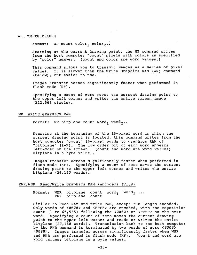
WP WRITE PIXELS
Format: WP count colorl color2 ••
Starting at the current drawing point, the WP command writes from the host computer "count" pixels with colors as specified by "color" number. (count and color are word values.)
This command allows you to transmit images as a series of pixel values. It is slower than the write Graphics RAM (WR) command (below), but easier to use.
Images transfer across significantly faster when performed in flash mode (KF).
Specifying a count of zero moves the current drawing point to the upper left corner and writes the entire screen image (322,560 pixels).
WR WRITE GRAPHICS RAM
Format: WR bitplane count word l word 2 ••
Starting at the beginning of the l6-pixel word in which the current drawing point is located, this command writes from the host computer "count" l6-pixel words to graphics RAM of "bitplane" (1-9). The low order bit of each word appears left-most on the screen. (count and word are word values; bitplane is a byte value).
Images transfer across significantly faster when performed in flash mode (KF). Specifying a count of zero moves the current drawing point to the upper left corner and writes the entire bitplane (20,160 words).
RNR,WNR Read/Write Graphics RAM (encoded) (Vl.8)
Format: WNR bitplane RNR bitplane
count word l count
Similar to Read RAM and Write RAM, except run length encoded. Only words of <0000> and <FFFF> are encoded, with the repetition count (1 to 65,535) following the <0000> or <FFFF> as the next word. Specifying a count of zero moves the current drawing point to the upper left corner and reads or writes the entire bitplane (20,160 words). Transmission back to the host computer by the RNR command is terminated by two words of zero <0000> <0000>. Images transfer across significantly faster when WNR and RNR are performed in flash mode (KF). (count and word are word values; bitplane is a byte value).
-33-
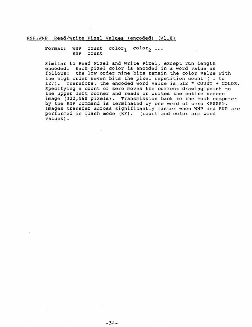
RNP,WNP Read/Write Pixel Values (encoded) (VI.S)
Format: WNP count colorl color2 ••• RNP count
Similar to Read Pixel and Write Pixel, except run length encoded. Each pixel color is encoded in a word value as follows: the low order nine bits remain the color value with the high order seven bits the pixel repetition count ( 1 to 127). Therefore, the encoded word value is,.5l2 * COUNT + COLOR. Specifying a count of zero moves the current drawiog;point to the upper left corner and reads or writes the entir~ screen image (322,560 pixels). Transmission back to the host computer by the RNP command is terminated by one word of zer'o <0000>. Images transfer across significantly faster when WNP and RNP are performed in flash mode (KF). (count and color ar,e word values) • '
-34-
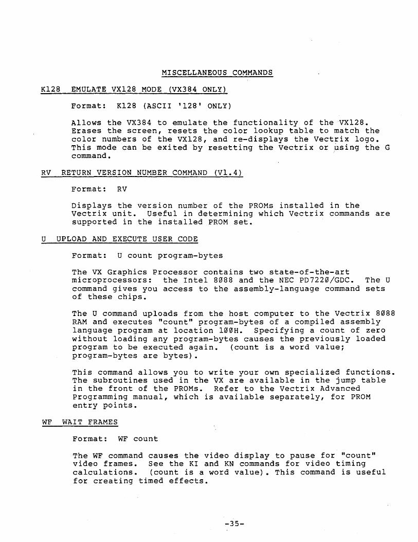
MISCELLANEOUS COMMANDS
K128 EMULATE VX128 MODE (VX384 ONLY)
Format: K128 (ASCII '128' ONLY)
Allows the VX384 to emulate the functionality of the VX128. Erases the screen, resets the color lookup table to match the color numbers of the VX128, and re-displays the vectrix logo. This mode can be exited by resetting the Vectrix or ~sing the G command. .
RV RETURN VERSION NUMBER COMMAND (Vl.4)
Format: RV
Displays the version number of the PROMs installed in the vectrix unit. Useful in determining which Vectrix commands are supported in the installed PROM set.
U UPLOAD AND EXECUTE USER CODE
Format: U count program-bytes
The VX Graphics Processor contains two state-of-the-art microprocessors: the Intel 8088 and the NEC PD7220/GDC. The U command gives you access to the assembly-language command sets of these chips.
The U command uploads from the host computer to the Vectrix 8088 RAM and executes "count" program-bytes of a compiled assembly language program at location l00H. Specifying a count of zero without loading any program-bytes causes the previously loaded program to be executed again. (count is a word value; program-bytes are bytes).
This command allows you to write your own specialized functions. The subroutines used in the VX are available in the jump table in the front of the PROMs. Refer to the Vectrix Advanced Programming manual, which is available separately, for PROM entry points.
WF WAIT FRAMES
Format: WF count
The WF command causes the video display to pause for "count" video frames. See the KI and KN commands for video timing calculations. (count is a word value). This command is useful for creating timed effects.
-35-
TUTORIAL
In general, Vectrix is designed to be driven by a host computer system. However, the simple ASCII commands understood by vectrix allow short display lists to be typed into the machine directly by the user. Doing some displays by hand is the best way to gain familiarity with vectrix commands.
For these simple exercises, you should program your host computer to transmit characters typed on the keyboard of your host computer to the Vectrix unit over the serial or parallel port. This can~often be done with just an operating system command. As an alternative, a stand alone ASCII terminal can be used with a cable having pirts 2 and 3 crossed and using the serial interface.
with power on, press the Reset switch on the back. Vectrix is now ready for a command. vectrix determines whether you are using ASCII or hexadecimal format from the COLOR and ERASE commands, so one of these should always be first in a new command sequence. Note that it is often advisable to initialize all the mode commands at the software level or by using the reset switch, even if the default modes (OR / 2-D / ABSOLUTE / BLANK / INTERLACED) are the ones desired, in case a previous command sequence may have changed any of the modes.
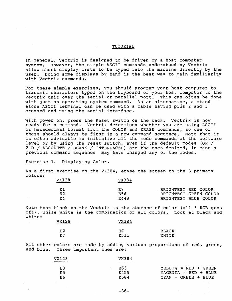
Exercise 1. Displaying Color.
As a first exercise on the VX384, erase the screen to the 3 primary colors:
VX128
El E2 E4
VX384
E7 E56 E448
BRIGHTEST RED COLOR BRIGHTEST GREEN COLOR BRIGHTEST BLUE COLOR
Note that black on the Vectrix is the absence of color (all 3 RGB guns off), while white is the combination of all colors. Look at black and white:
VXl28
E0 E7
VX384
E0 E511
BLACK WHITE
All other colors are made by adding various proportions of red, green, and blue. Three important ones are:
VXl28
E3 E5 E6
VX384
E63 E455 E504
-36-
YELLOW = RED + GREEN MAGENTA = RED + BLUE CYAN = GREEN + BLUE
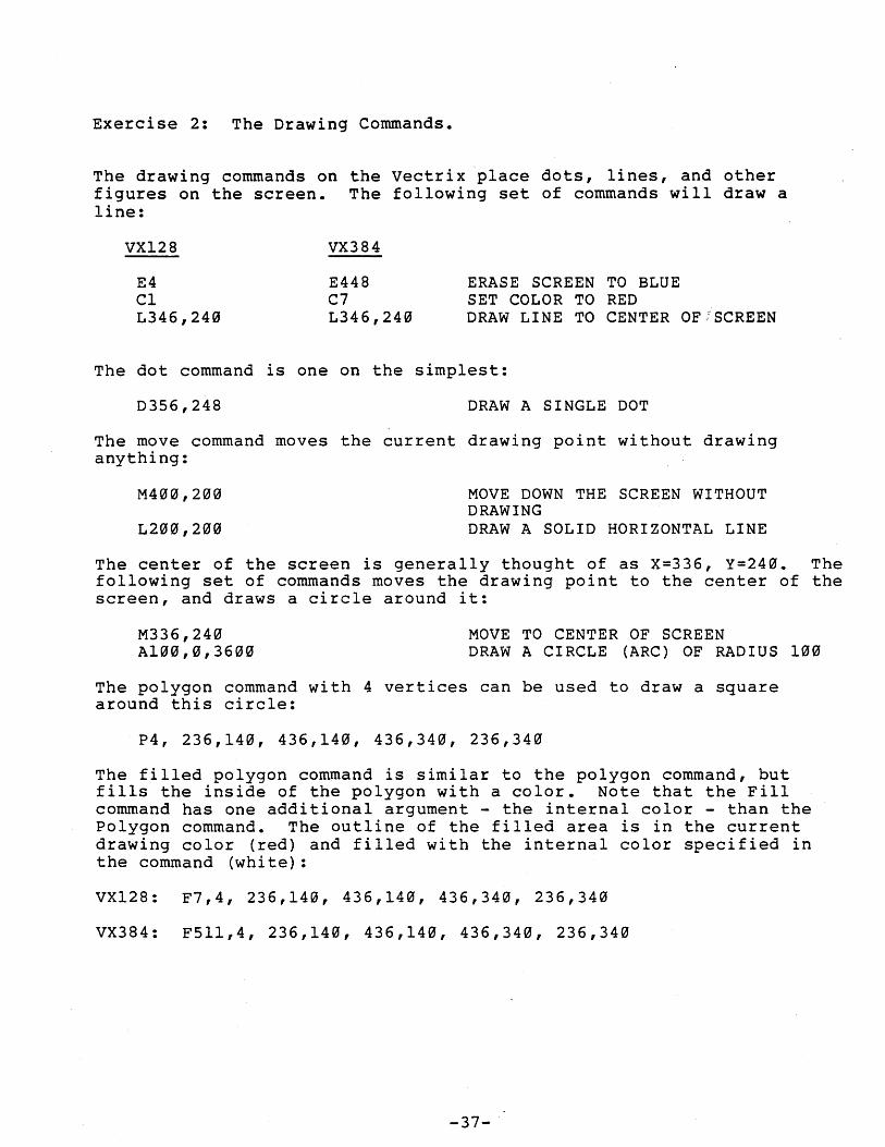
Exercise 2: The Drawing Commands.
The drawing commands on the vectrix place dots, lines, and other figures on the screen. The following set of commands will draw a line:
VX128
E4 C1 L346,240
VX384
E448 C7 L346,240
ERASE SCREEN TO BLUE SET COLOR TO RED DRAW LINE TO CENTER OF/SCREEN
The dot command is one on the simplest:
D356,248 DRAW A SINGLE DOT
The move command moves the current drawing point without drawing anything:
M400,200
L200,200
MOVE DOWN THE SCREEN WITHOUT DRAWING DRAW A SOLID HORIZONTAL LINE
The center of the screen is generally thought of as X=336, Y=240. The following set of commands moves the drawing point to the center of the screen, and draws a circle around it:
M336,240 A100,0,3600
MOVE TO CENTER OF SCREEN DRAW A CIRCLE (ARC) OF RADIUS 100
The polygon command with 4 vertices can be used to draw a square around this circle:
P4, 236,140, 436,140, 436,340, 236,340
The filled polygon command is similar to the polygon command, but fills the inside of the polygon with a color. Note that the Fill command has one additional argument - the internal color - than the Polygon command. The outline of the filled area is in the current drawing color (red) and filled with the internal color specified in the command (white):
VX128: F7,4, 236,140, 436,140, 436,340, 236,340
VX384: F511,4, 236,140, 436,140, 436,340, 236,340
-37-
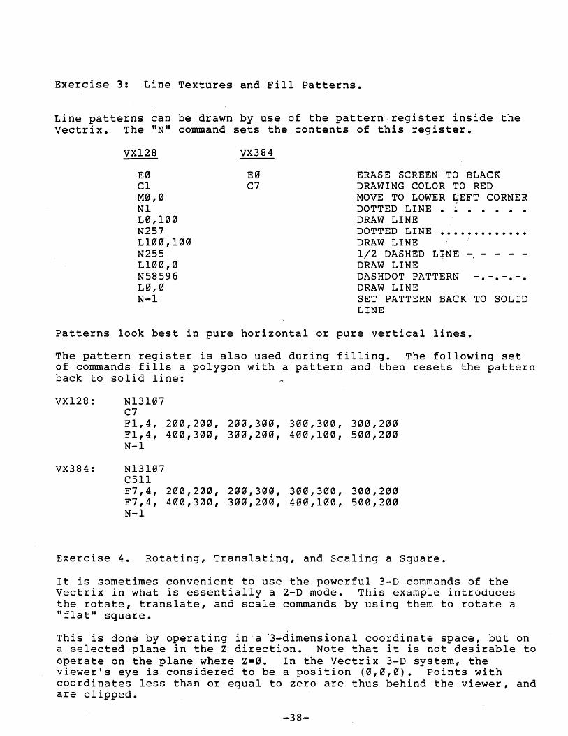
Exercise 3: Line Textures and Fill Patterns.
Line patterns can be drawn by use of the pattern register inside the vectrix. The "N" command sets the contents of this register.
VX128
E0 Cl M0,0 N1 L0,100 N257 L100,100 N255 L100,0 N58596 L0,0 N-l
VX384
E0 C7
ERASE SCREEN TO BLACK DRAWING COLOR TO RED MOVE TO LOWER LEFT CORNER DOTTED LINE • ~ • • • • • DRAW LINE DOTTED LINE ••••••••••••• DRAW LINE 1/2 DASHED L~NE - - - - -DRAW LINE DASHDOT PATTERN -.-.-.-. DRAW LINE SET PATTERN BACK TO SOLID LINE
Patterns look best in pure horizontal or pure vertical lines.
The pattern register is also used during filling. The following set of commands fills a polygon with a pattern and then resets the pattern back to solid line:
VX128: N13l07 C7 Fl,4, 200,200, 200,300, 300,300, 300,200 F1,4, 400,300, 300,200, 400,100, 500,200 N-l
VX384: N13107 C5l1 F7,4, 200,200, 200,300, 300,300, 300,200 F7,4, 400,300, 300,200, 400,100, 500,200 N-l
Exercise 4. Rotating, Translating, and Scaling a Square.
It is sometimes convenient to use the powerful 3-D commands of the vectrix in what is essentially a 2-D mode. This example introduces the rotate, translate, and scale commands by using them to rotate a "flat" square.
This is done by operating in' a °3-dimensional coordinate space, but on a selected plane in the Z direction. Note that it is not desirable to operate on the plane where Z=0. In the Vectrix 3-D system, the viewer's eye is considered to be a position (0,0,0). Points with coordinates less than or equal to zero are thus behind the viewer, and are clipped.
-38-
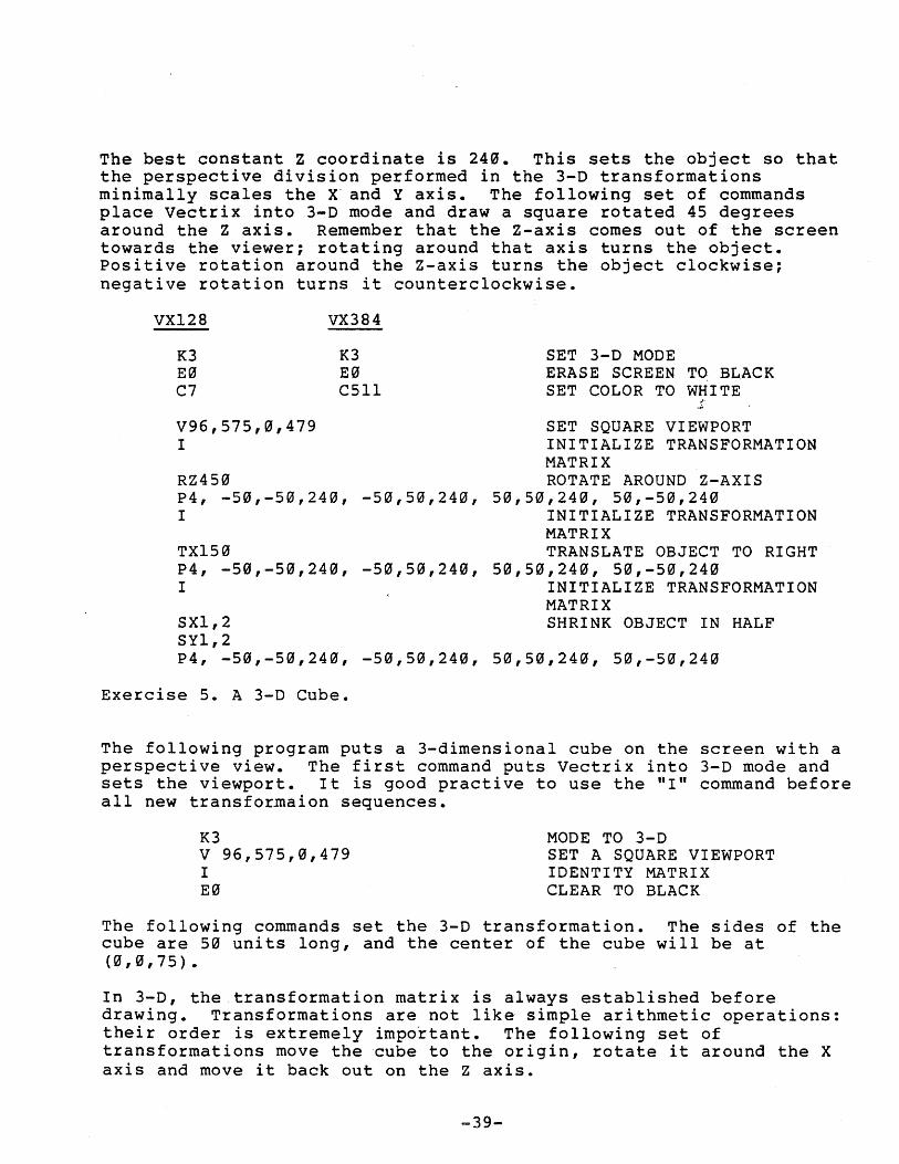
The best constant Z coordinate is 24~. This sets the object so that the perspective division performed in the 3-D transformations minimally scales the X' and Y axis. The following set of commands place Vectrix into 3-D mode and draw a square rotated 45 degrees around the Z axis. Remember that the Z-axis comes out of the screen towards the viewer; rotating around that axis turns the object. positive rotation around the Z-axis turns the object clockwise; negative rotation turns it counterclockwise.
VX128
K3 E~ C7
V96,575,~,479
I
RZ450
VX384
K3 E~ C51l
P4, -50,-50,240, -50,50,240, I
TX150 P4, -5~,-50,240, -50,50,240, I
SXl,2 SY1,2
SET 3-D MODE ERASE SCREEN TO BLACK SET COLOR TO WHITE
SET SQUARE VIEWPORT INITIALIZE TRANSFORMATION MATRIX ROTATE AROUND Z-AXIS
50,50,240, 50,-50,240 INITIALIZE TRANSFORMATION MATRIX TRANSLATE OBJECT TO RIGHT
50,50,240, 50,-50,240 INITIALIZE TRANSFORMATION MATRIX SHRINK OBJECT IN HALF
P4, -50,-50,240, -50,50,240, 50,50,240, 50,-50,240
Exercise 5. A 3-D Cube.
The following program puts a 3-dimensional cube on the screen with a perspective view. The first command puts Vectrix into 3-D mode and sets the viewport. It is good practive to use the "I" command before all new transformaion sequences.
K3 V 96,575,0,479 I E0
MODE TO 3-D SET A SQUARE VIEWPORT IDENTITY MATRIX CLEAR TO BLACK
The following commands set the 3-D transformation. The sides of the cube are 50 units long, and the center of the cube will be at (0,0,75).
In 3-D, the transformation matrix is always established before drawing. Transformations are not like simple arithmetic operations: their order is extremely important. The following set of transformations move the cube to the origin, rotate it around the X axis and move it back out on the Z axis.
-39-
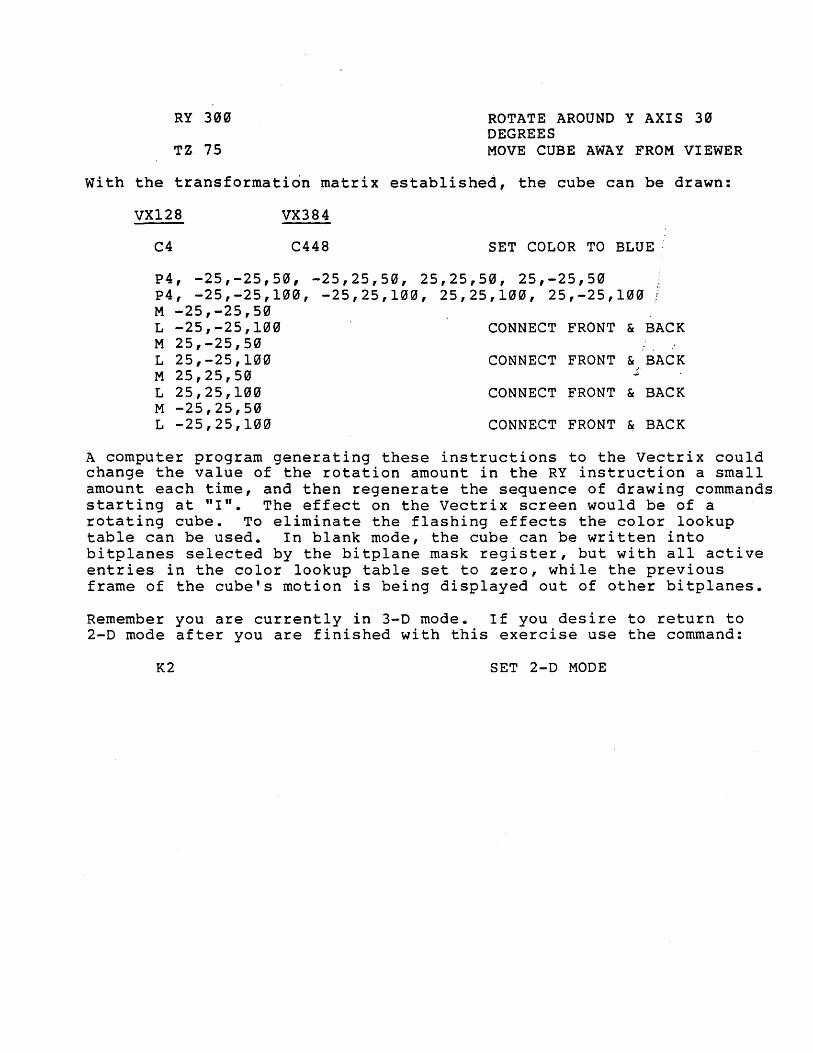
RY 300
TZ 75
ROTATE AROUND Y AXIS 30 DEGREES MOVE CUBE AWAY FROM VIEWER
with the transformation matrix established, the cube can be drawn:
VX128
C4
VX384
C448 SET COLOR TO BLUE:
P4, -25,-25,50, -25,25,50, 25,25,50, 25,-25,50 P4, -25,-25,100, -25,25,100, 25,25,100, 25,-25,100 M -25,-25,50 L -25,-25,100 M 25,-25,50 L 25,-25,100 M 25,25,50 L 25,25,100 M -25,25,50 L -25,25,100
CONNECT FRONT & BACK
CONNECT FRONT & BACK ; ~
CONNECT FRONT & BACK
CONNECT FRONT & BACK
A computer program generating these instructions to the Vectrix could change the value of the rotation amount in the RY instruction a small amount each time, and then regenerate the sequence of drawing commands starting at "I". The effect on the vectrix screen would be of a rotating cube. To eliminate the flashing effects the color lookup table can be used. In blank mode, the cube can be written into bitplanes selected by the bitplane mask register, but with all active entries in the color lookup table set to zero, while the previous frame of the cube's motion is being displayed out of other bitplanes.
Remember you are currently in 3-D mode. If you desire to return to 2-D mode after you are finished with this exercise use the command:
K2 SET 2-D MODE
TERMINAL COMMANDS
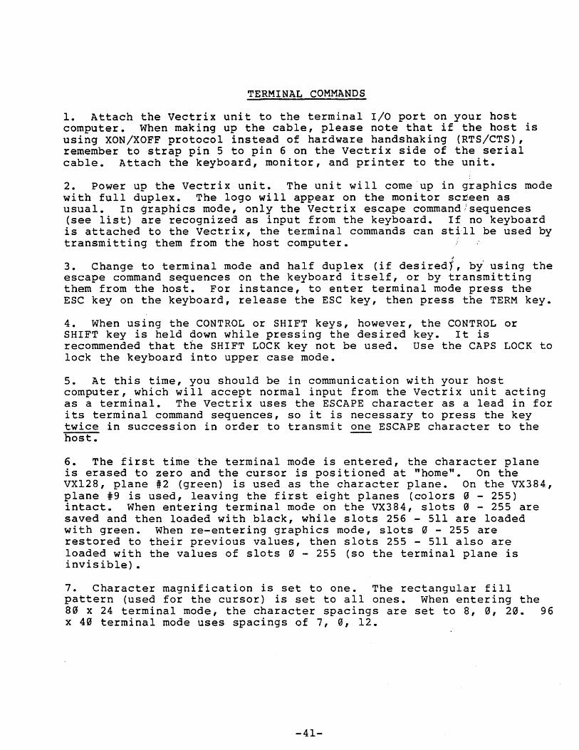
1. Attach the vectrix unit to the terminal I/O port on your host computer. When making up the cable, please note that if the host is using XON/XOFF protocol instead of hardware handshaking (RTS/CTS), remember to 'strap pin 5 to pin 6 on the vectrix side of the serial cable. Attach the keyboard, monitor, and printer to the unit.
2. Power up the vectrix unit. The unit will come'up in graphics mode with full duplex. The logo will appear on the monitor screen as usual. In graphics mode, only the Vectrix escape command .. :sequences (see list) are recognized as input from the keyboard. If no keyboard is attached to the Vectrix, the terminal commands can still be used by transmitting them from the host computer.
~.
3. Change to terminal mode and half duplex (if desiredY, by using the escape command sequences on the keyboard itself, or by transmitting them from the host. For instance, to enter terminal mode press the ESC key on the keyboard, release the ESC key, then press the TERM key.
4. When using the CONTROL or SHIFT keys, however, the CONTROL or SHIFT key is held down while pressing the desired key. It is recommended that the SHIFT LOCK key not be used. Use the CAPS LOCK to lock the keyboard into upper case mode.
5. At this time, you should be in communication with your host computer, which will accept normal input from the vectrix unit acting as a terminal. The Vectrix uses the ESCAPE character as a lead in for its terminal command sequences, so it is necessary to press the key twice in succession in order to transmit one ESCAPE character to the host.
6. The first time 'the terminal mode is entered, the character plane is erased to zero and the cursor is positioned at "home". On the VX128, plane #2 (green) is used as the character plane. On the VX384, plane #9 is used, leaving the first eight planes (colors ~ - 255) intact. When entering terminal mode on the VX384, slots ~ - 255 are saved and then loaded with black, while slots 256 - 511 are loaded with green. When re-entering graphics mode, slots ~ - 255 are restored to their previous values, then slots 255 - 511 also are loaded with the values of slots ~ - 255 (so the terminal plane is invisible).
7. Character magnification is set to one. The rectangular fill pattern (used for the cursor) is set to all ones. When entering the 8~ x 24 terminal mode, the character spacings are set to 8, ~, 2~. 96 x 4~ terminal mode uses spacings of 7, 0, 12.
-41-
Terminal Characteristics
The terminal has 40 rows of 96 characters per row (or 24 rows of 80 characters). Arrow functions (backspace, linefeed, upfeed, and forward space, which are CONTROL-H,-J,-K, and -L, respectively,) permit movement of the cursor within the boundaries of the screen. The Vectrix unit does not perform cursor wraparound. An attempt to write characters past the screen limits has the following results:
1. On the top edge or left side, the cursor remains in the last visible position. No further action is taken. !
2. On the right side, an automatic carriage return/line feed is issued, and the remaining characters are displayed on the next line.
~
3. On the bottom edge, the screen is scrolled (as of version 1.7) and the characters are displayed on the new bottom line.
-42-
DECIMAL
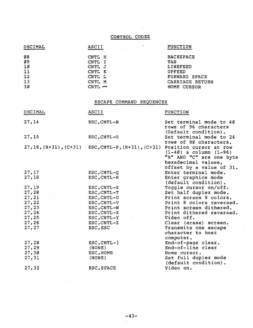
~8 ~9 1~ 11 12 13 3~
ASCII
CNTL H CNTL I CNTL J CNTL K CNTL L CNTL M CNTL ,-.J
CONTROL CODES
ESCAPE COMMAND SEQUENCES
FUNCTION
BACKSPACE TAB LINEFEED UPFEED FORWARD SPACE CARRIAGE RETURN HOME CURSOR
DECIMAL ASCII FUNCTION
27,14 ESC,CNTL-N Set terminal mode to 4~ rows of 96 characters (Default condition).
27,15 ESC,CNTL-O Set terminal mode to 24 rows of 8~ characters.
27,16,(R+31),(C+31) ESC,CNTL-P,(R+31),(C+31) Position cursor at row (1-4~) & column (1-96) "R" AND "C" are one byte hexadecimal values,
27,17 ESC,CNTL-Q 27,18 ESC,CNTL-R
27,19 ESC,CNTL-S 27,20 ESC,CNTL-T 27,21 ESC,CNTL-U 27,22 ESC,CNTL-V 27,23 ESC,CNTL-W 27,24 ESC,CNTL-X 27,25 ESC,CNTL-Y 27,26 ESC,CNTL-Z 27,27 ESC,ESC
27,28 ESC,CNTL-} 27,29 (NONE) 27,30 ESC,HOME 27,31 (NONE)
27,32 ESC,SPACE
-43-
offset by a value of 31. Enter terminal mode. Enter graphics mode (default condition). Toggle cursor on/off. Set half duplex mode. Print screen 8 colors. Print 8 colors reversed. Print screen dithered. Print dithered reversed. Video off. Clear (erase) screen. Transmits one escape character to host computer. End-of-page clear. End-of-line clear Home cursor. Set full duplex mode (default condition).
Video on.
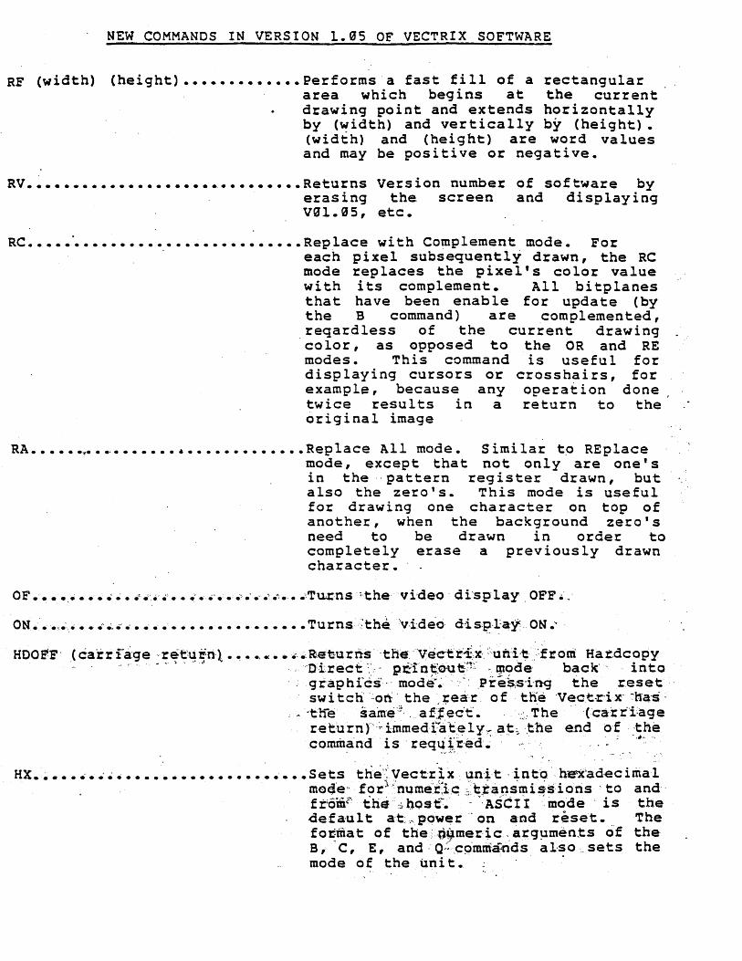
NEW COMMANDS IN VERSION 1.05 OF VECTRIX SOFTWARE
RF (width) (height) ••••••••••••• Performs a fast fill of a rectangular area which begins at the current drawing point and extends horizontally by (width) and vertically by (height). (width) and (height) are word values and may be positive or negative.
RV •••••••••••••••••••••.••••••••• Returns Version number of software by erasing the screen and displaying V0l.05, etc.
RC ••••• ~ •••••••••••••••••••••••• Replace with Complement mode. For . each pixel subsequently drawn, the RC
mode replaces the pixel's color value with its complement. All bitplanes that have been enable for update (by the B command) are .complemented,
. reqardless of the current drawing color, as opposed to the OR and RE modes. This command is useful for disp laying cursors or crosshai rs, for example, because any operation done twice results in a return to the original image
RA •••••• ~ ••••••••••••••••••••••• Replace All mode. Similar t9 REplace mode, except that not only are one's in the "pattern register drawn, but also the zero 1 s. This mode is useful for drawing one character on top of another, when the background zero's need to be drawn in order to completely erase a previously drawn character.
OF ............. ' •..• .I' ••• ' ••.••• ' .... ' .0 ... ',Turns;,the video' display , OFF.·.·
ON ••• ,.' ••• ' e' e ... .i ••••••••••••••••••• Turns:'the. ·'vide·o· dis:p'.~:a·Y'. ON."
HCOE'F' (carr rage ··r~f::t..1 ~n·t •••• 0 •• ., e'. ~etu rri's' ·the. ···vec·t:r~\x·\~ni,t·.·from Har.dcopy '.' ., , . ' ... , •. 'II ,,··O:-i.rect ':.'0" p~in~~e~'!:~' .1J1ode· back" into
'; gr·aphfcs·,.· mode"~ .. < .pre~,si·n-g the r.eset'· swi tch~on:'" the ,;ea'r. of ,th:e 'V~ct.r-ix· ~ha's'
, ~ -tli"e same:::. afJ~c't. ',;: The {ca'rr'i:age return)",,';' iinmedf"at,~ly~a~~ ',the e,nd o·E.-the comm~'nd . is 'req~Jr·ed.' "',' .. -; . .I~- .
HX. ~ .............................. Sets the"~Vect'x:ix un'it·into' hex'adecirrial mo4'e" for:\:'nQ,me'tlc ~·ttansmis<s:ioris . to and' fromt'the ',~ bost~~ . -.~ '~ASCI'I~ mo'de . is the defa'ult a·t.;,.,.power·· on and reset. The fo~mat of the: .. gy.mer~c, a~g~men.ts o'f the B,' C, E, and· O'~·:c9.·mm:artds also ' .. sets the mode of the unit. .
" .