Embed Size (px)
Citation preview
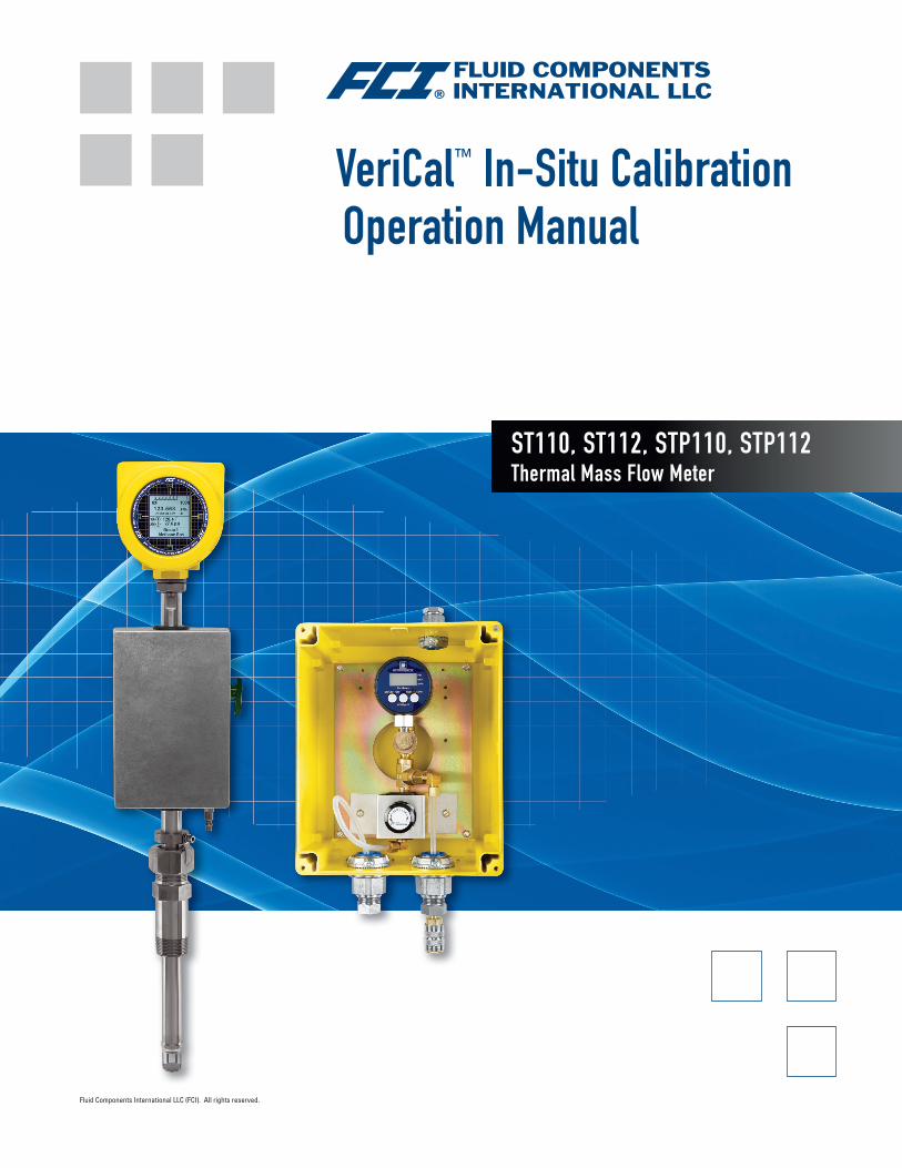
ST110, ST112, STP110, STP112 Thermal Mass Flow Meter
VeriCal™ In-Situ Calibration Operation Manual
Fluid Components International LLC (FCI). All rights reserved.

Notice of Proprietary RightsThis document contains confidential technical data, including trade secrets and proprietary information which is the property of Fluid Components International LLC (FCI). Disclosure of this data to you is expressly conditioned upon your assent that its use is limited to use within your company only (and does not include manufacture or processing uses). Any other use is strictly prohibited without the prior written consent of FCI.
© Copyright 2011 by Fluid Components International LLC. All rights reserved. FCI is a registered trademark of Fluid Components International LLC. Information subject to change without notice.
ST100 Series VeriCal Operation Manual
Fluid Components International LLC 1
IntroductionThis manual guides the user of the VeriCal instrumentation through an initial gathering of in-situ baseline data. This baseline line data will then be compared to data gathered during similar future verification processes to determine if the system is operating within factory specifications.
Theory of OperationThe VeriCal system uses a sonic nozzle to consistently control the amount of compressed air (or nitrogen) injected onto the thermal flow transducer located on the end of the probe assembly. It is critical to use the same gas for subsequent VeriCal runs to ensure repeatability.
The operating principle of the sonic nozzle requires the total or absolute pressure on the high side of the nozzle to be greater than 20.0 PSIA. The pressure difference between the high side of the sonic nozzle and the process pressure (low-pressure side of the nozzle) must be greater than 2:1. When these two requirements are met, a repeatable flow is injected onto the thermal flow transducer.
SetupFCI Recommends that this procedure be run during the commissioning process of the instrument to determine an initial installed baseline calibration and to document any installed offset from the factory VeriCal baseline.
Frequency: Every 18 months minimum, every six months is recommended. After the process has been performed a couple times the customer should determine the required verification frequency based upon the process conditions.
This procedure makes the assumption that the instrument has been installed and is completely functional in the normal operating condition and orientation. The customer should also have access to the factory VeriCal calibration certificate.
Note: All standard safety procedures must be followed during the verification process. This procedure assumes the standard packing gland process connection. Your process connections may vary. It is critical to establish a Field Baseline upon receiving your ST100. This will ensure a greater likelihood of repeatability and establish a history of the VeriCal data.
• Apply the proper input power and allow for a 30-minute warmup. It is critical that the electronics and the sensor be fully warmed and stable prior to the VeriCal process. Failure to allow the proper warmup time can impact repeatability.
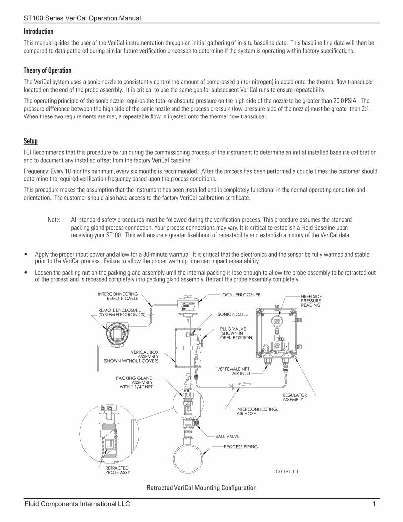
• Loosen the packing nut on the packing gland assembly until the internal packing is lose enough to allow the probe assembly to be retracted out of the process and is recessed completely into packing gland assembly. Retract the probe assembly completely.
Retracted VeriCal Mounting Configuration
LOCAL ENLCOSURE
VERICAL BOXASSEMBLY
(SHOWN WITHOUT COVER)
INTERCONNECTINGREMOTE CABLE
PACKING GLANDASSEMBLY
WITH 1 1/4 " NPT
REMOTE ENCLOSURE(SYSTEM ELECTRONICS)
PLUG VALVE(SHOWN INOPEN POSITION)
INTERCONNECTING,AIR HOSE.
1/8" FEMALE NPT,AIR INLET
BALL VALVE
PROCESS PIPING
C01061-1-1
REGULATORASSEMBLY
RETRACTEDPROBE ASSY
HIGH SIDEPRESSUREREADING
SONIC NOZZLE
ST100 Series VeriCal Operation Manual
2 Fluid Components International LLC
• Level the orientation flat on the probe assembly using a standard bubble level and tighten the packing nut to secure the assembly. To optimize the repeatability of the verification process, the position and orientation of the probe assembly should be identical every time the process is performed.
• Attach the regulator assembly with the interconnecting hose to the inlet quick disconnect fitting on the probe assembly if it is not permanently installed.
• Attach the calibration gas supply, typically compressed air (or Nitrogen), to the inlet side of the regulator assembly. Back out the pressure con-trol regulator. Open the supply valve to the VeriCal pressure regulator box.
• Slowly apply 100 PSIG to the VeriCal setup and verify that the system is leak free using a liquid leak detection fluid on all junction points. This should also ensure a steady flow across the sensors and remove any debris that might be on the thermowells or the outlet of the VeriCal tube. Reduce the pressure on the system to 25.0 PSIG.
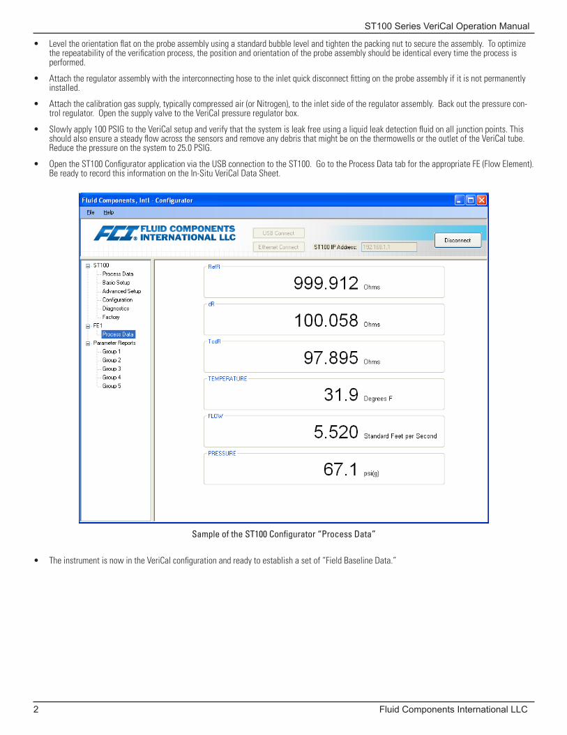
• Open the ST100 Configurator application via the USB connection to the ST100. Go to the Process Data tab for the appropriate FE (Flow Element). Be ready to record this information on the In-Situ VeriCal Data Sheet.
• The instrument is now in the VeriCal configuration and ready to establish a set of “Field Baseline Data.”
Sample of the ST100 Configurator “Process Data”
ST100 Series VeriCal Operation Manual
Fluid Components International LLC 3
Procedure
• Verify that the VeriCal pressure gauge indicates 25.0 PSIG (+/- 0.20 PSIG). Note: using the exact pressure levels allows one to compare the cur-rent findings to the FCI Factory findings and any subsequent findings.
• Allow the instrument to stabilize by sustaining the pressure for a minimum of 5 minutes. Observing the flow and temperature reading stability on the ST100 Configurator to verify that the instrument has come to equilibrium.
• Record the VeriCal pressure as indicated on the regulator assembly pressure indicator and the ST100 data that is shown on the Configurator: RefR, dR, TCdR, Temperature, Flowrate and optionally the output current across a precision 250Ω resistor.
• Repeat this process for 50, 75 and 100 PSIG pressures.
• The recorded values are the instrument’s in-situ baseline calibration readings. All future verification readings will be compared to these baseline values and should be within 2-5% of the Field Baseline Data readings.
• It is advisable to complete one more round of “Field Check Data” to establish a pattern of repeatability for this specific combination.
Note: This step is not mandatory, but it will help to understand the VeriCal system and what can be expected for future verifications.
• The ST100 Configurator application can now be closed.
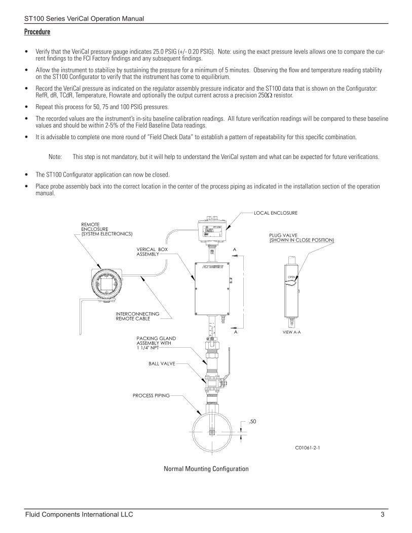
• Place probe assembly back into the correct location in the center of the process piping as indicated in the installation section of the operation manual.
Normal Mounting Configuration
.50
A
A
OPEN
PLUG VALVE(SHOWN IN CLOSE POSITION)
VIEW A-A
VERICAL BOXASSEMBLY
LOCAL ENCLOSURE
REMOTEENCLOSURE(SYSTEM ELECTRONICS)
C01061-2-1
INTERCONNECTINGREMOTE CABLE
PACKING GLANDASSEMBLY WITH1 1/4" NPT
BALL VALVE
PROCESS PIPING

ST100 Series VeriCal Operation Manual
4 Fluid Components International LLC
INTENTIONALLY LEFT BLANK
ST100 Series VeriCal Operation Manual
Fluid Components International LLC 5
1755 La Costa Meadows Drive, San Marcos, CA 92078-5115Phone: 760-744-6950 Toll Free (US): 800-854-1993 Fax: 760-736-6250
www.fluidcomponents.com
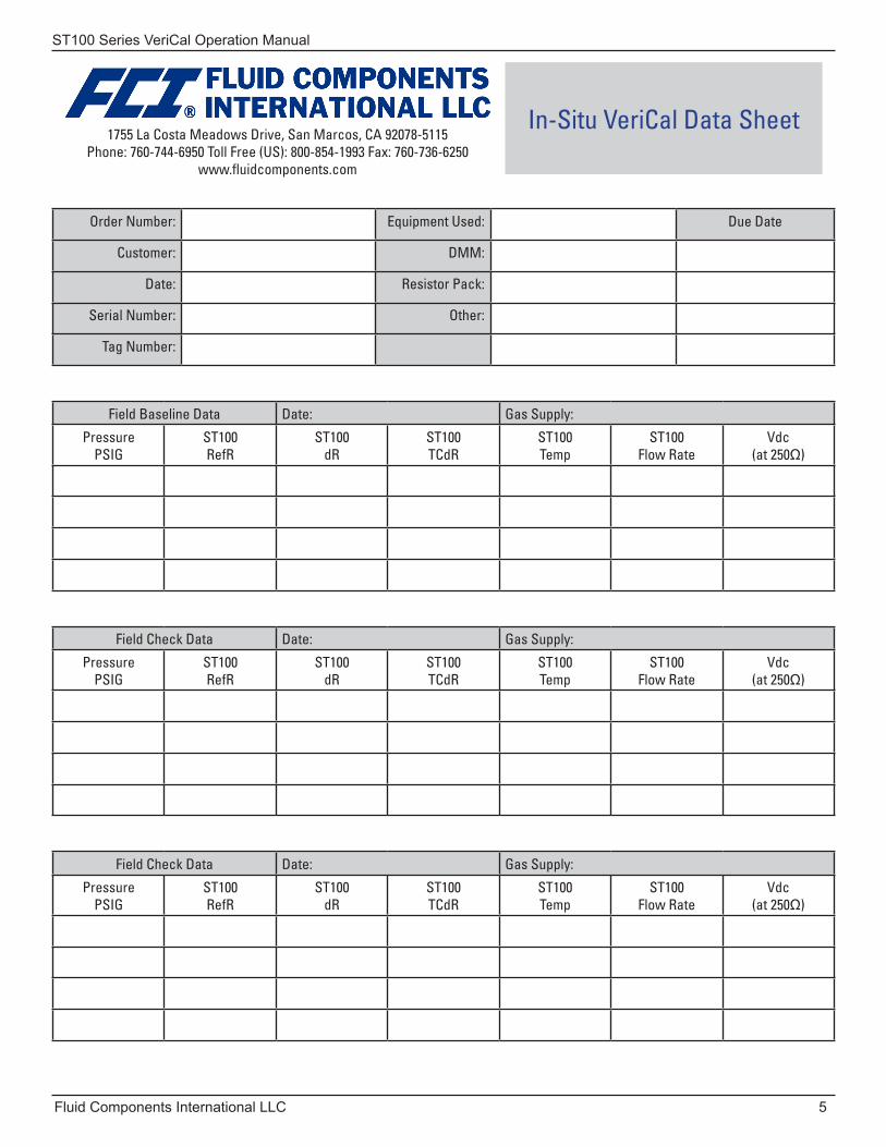
In-Situ VeriCal Data Sheet
Order Number: Equipment Used: Due Date
Customer: DMM:
Date: Resistor Pack:
Serial Number: Other:
Tag Number:
Field Baseline Data Date: Gas Supply:
PressurePSIG
ST100RefR
ST100dR
ST100TCdR
ST100Temp
ST100Flow Rate
Vdc(at 250Ω)
Field Check Data Date: Gas Supply:
PressurePSIG
ST100RefR
ST100dR
ST100TCdR
ST100Temp
ST100Flow Rate
Vdc(at 250Ω)
Field Check Data Date: Gas Supply:
PressurePSIG
ST100RefR
ST100dR
ST100TCdR
ST100Temp
ST100Flow Rate
Vdc(at 250Ω)

ST100 Series VeriCal Operation Manual
6 Fluid Components International LLC
INTENTIONALLY LEFT BLANK
ST100 Series VeriCal Operation Manual
Fluid Components International LLC 7
Customer Service / Technical SupportFCI provides full in-house technical support. Additional technical representation is also provided by FCI field representatives. Before contacting a field or in-house representative, please perform the troubleshooting techniques outlined in this document.
By MailFluid Components International LLC
1755 La Costa Meadows Dr.
San Marcos, CA 92078-5115 USA
Attn: Customer Service Department
By PhoneContact the area FCI regional representative. If a field representative is unable to be contacted or if a situation is unable to be resolved, contact the FCI Customer Service Department toll free at 1 (800) 854-1993.
By FaxTo describe problems in a graphical or pictorial manner, send a fax including a phone or fax number to the regional representative. Again, FCI is available by facsimile if all possibilities have been exhausted with the authorized factory representative. Our Fax number is 1 (760) 736-6250; it is available 7 days a week, 24 hours a day.
By E-MailFCI Customer Service can be contacted by e-mail at: [email protected].
Describe the problem in detail making sure a telephone number and best time to be contacted is stated in the e-mail.
International SupportFor product information or product support outside the contiguous United States, Alaska, or Hawaii, contact your country’s FCI International Representative or the one nearest to you.
After Hours SupportFor product information visit FCI at www.fluidcomponents.com. For product support call 1 (800) 854-1993 and follow the prerecorded instructions.
Point of ContactThe point of contact for service, or return of equipment to FCI is your authorized FCI sales/service office. To locate the office nearest you, please go to www.fluidcomponents.com.

ST100 Series VeriCal Operation Manual
8 Fluid Components International LLC
NOTES
ST100 Series VeriCal Operation Manual
Fluid Components International LLC 9
NOTES
06EN003408 Rev. A ST100 Series VeriCal Operation Manual
Fluid Components International LLC
FCI’s Complete Customer Commitment. WorldwideISO 9001 and AS9100 Certified
Notice of Proprietary RightsThis document contains confidential technical data, including trade secrets and proprietary information which is the property of Fluid Components International LLC (FCI). Disclosure of this data to you is expressly conditioned upon your assent that its use is limited to use within your company only (and does not include manufacture or processing uses). Any other use is strictly prohibited without the prior written consent of FCI.
Visit FCI on the Worldwide Web: www.fluidcomponents.com
FCI World Headquarters1755 La Costa Meadows Drive | San Marcos, California 92078 USA | Phone: 760-744-6950 Toll Free (US): 800-854-1993 Fax: 760-736-6250
FCI EuropePersephonestraat 3-01 | 5047 TT Tilburg, The Netherlands | Phone: 31-13-5159989 Fax: 31-13-5799036
FCI Measurement and Control Technology (Beijing) Co., LTD | www.fluidcomponents.cnRoom 107, Xianfeng Building II, No.7 Kaituo Road, Shangdi IT Industry Base, Haidian District | Beijing 100085, P. R. ChinaPhone: 86-10-82782381 Fax: 86-10-58851152
© Copyright 2011 by Fluid Components International LLC. All rights reserved. FCI is a registered trademark of Fluid Components International LLC. Information subject to change without notice.