Embed Size (px)
Citation preview
1
Arachnipod User ManualVersion 6.0
© Copyright: FERNO AUSTRALIA
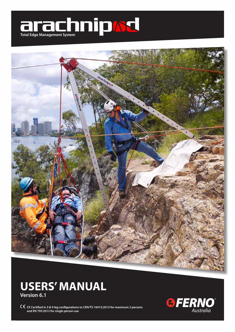
Total Edge Management System
USERS’ MANUALVersion 6.1
CE Certified in 3 & 4 leg configurations to CEN/TS 16415:2013 for maximum 2 persons and EN 795:2012 for single person use Australia

Australia
2Arachnipod User Manual Version 6.1
DOC ID: 00184-AU-V06 (2015/03)
CE Compliance Information 3
Introduction 4
WARNINGS 5
Working Load Limits (WLL) 6
Tripod and Kit Contents 7
General 9
Intended Purpose 9
Care, Maintenance & Storage 9
Transportation 10
Safety Information 10
Life Cycle 10
Non-metallic Components 10
Inspection of the Arachnipod 11
Repairs 11
Safe Working Practices 11
Principles of Edge Management 12
Critical Point Analysis 13
(High change of direction 13
The Two Rope System 14
Understanding the forces at a change of direction pulley 15
Understanding the forces being applied to the Arachnipod 15
Assessing the stability of your Arachnipod rigging 16
Tripod Stabilisation 16
Arachnipod Parts 17Standard Leg 17
Pulley Leg 17
Pulley Leg 17
Reverse Head, Quad Plate and Quad Pod 18
Gin Head 18
Rigging Plate 18
Leg with a Standard Foot 19
Spike Foot & Soft Ground Shoe 19
Hold Down Stake 19
Bridge Beams and Trolley 20
Equipment Bracket 20
Steps 20
Bridge Systems 21
Arachnipod Assembly 22
Stabilisation 26
Anchoring the Arachnipod 26
Using an Arachnipod leg as an anchor 26
Tripod Stabilisation 27
Lazy Leg Tripod Stabilisation 28
Quadpod Stabilisation 29
A-Frame Stabilisation 30
Method 1 Standard A-frame 30
Method 2 Sideways A-frame (SA-frame) 30
Method 3 A-frame with a lazy leg 32
Gin Pole Stabilisation 33
Using a single leg to manage a handrail 34
Bridge Stabilisation 35
Accessories 36
Foot Options for your Arachnipod 36
Additional Accessories for your Arachnipod 37
Accessory Instructions Winch 38
ISC UB171 Fall Arrest Adaptor Bracket 39
Lazy Leg Extension Kit 40
Lazy Leg Adaptor Plug 41
Equipment Bracket with 2:1 Rigging 42
Bridge Ratchet Strap Kit 43
Arachnipod Inspection 45
Arachnipod Disassembly 46
Leg Inspection 46
Inspecting the Heads of each leg 47
Standard Leg 47
Pulley Leg 47
Lazy Leg 48
Foot Inspection 48
Standard Feet 48
Spike Foot 48
Soft Ground Shoe 49
Hold Down Stake Inspection 49
Gin Head Inspection 49
Rigging Plate Inspection 50
Equipment Bracket Inspection 50
Reverse Head Inspection 50
Bridge Beam & Trolley Inspection 51
Arachnipod Winch Inspection 51
FormsArachnipod Kit Records 53
Regular & Annual Inspections 54
TABLE OF CONTENTS
3
Arachnipod User ManualVersion 6.0
© Copyright: FERNO AUSTRALIA
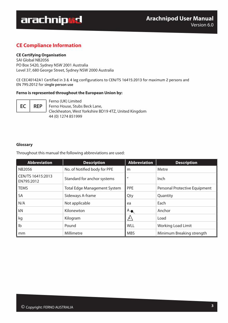
CE Compliance Information
CE Certifying OrganisationSAI Global NB2056PO Box 5420, Sydney NSW 2001 AustraliaLevel 37, 680 George Street, Sydney NSW 2000 Australia
CE CEC40142A1 Certified in 3 & 4 leg configurations to CEN/TS 16415:2013 for maximum 2 persons and EN 795:2012 for single person use
Ferno is represented throughout the European Union by:
Ferno (UK) Limited Ferno House, Stubs Beck Lane, Cleckheaton, West Yorkshire BD19 4TZ, United Kingdom 44 (0) 1274 851999
Glossary
Throughout this manual the following abbreviations are used:
Abbreviation Description Abbreviation Description
NB2056 No. of Notified body for PPE m Metre
CEN/TS 16415:2013EN795:2012 Standard for anchor systems “ Inch
TEMS Total Edge Management System PPE Personal Protective Equipment
SA Sideways A-frame Qty Quantity
N/A Not applicable ea Each
kN Kilonewton A Anchor
kg Kilogram Load
lb Pound WLL Working Load Limit
mm Millimetre MBS Minimum Breaking strength
EC REP
Australia
4Arachnipod User Manual Version 6.1
DOC ID: 00184-AU-V06 (2015/03)
Introduction
Congratulations on your purchase of the Arachnipod. The Arachnipod is a total edge management system that will empower the end user with a wide range of configuration options.
The complete Arachnipod total edge management system (TEMS) can be rigged as a:
» Gin Pole (mono pole / monopod) » A-frame (bipod) » Sideways A-frame (SA-frame) » Tripod » Quadpod » Lazy Leg or Easel Leg Tripod » Handrail monopod (used to support to a handrail) » Bridge
Components can be added or removed as required so that the Arachnipod compliments existing structural or natural features making it the most versatile edge management solution on the planet.
Ferno knows that rigging is not always conducted on a flat surface or with a clean edge so the Arachnipod was designed with every conceivable task in mind. From the harshest vertical rescue conditions to a simple tripod for a confined space entry task, the Arachnipod will provide the flexibility that end users demand.
The versatility of the Arachnipod will appeal to a wide range of end users including rescuers, mines rescue, industrial rope access workers, construction, and film industries.
The end user can purchase as little or as much Arachnipod hardware to suit their scope of operations making the Arachnipod an edge management system that is both affordable and upgradeable to suit changes in operational needs.
With the appropriate training, the Arachnipod can be used in a variety of configurations and in any number of environments from wilderness applications to industrial rope access scenarios.

5
Arachnipod User ManualVersion 6.0
© Copyright: FERNO AUSTRALIA
Activities conducted at height can be dangerous resulting in injury or death. Do not use this device unless you have:
1. Read and understood the User’s Manual2. Received appropriate training3. Ensured a competent person has conducted a risk assessment for the specific task4. Carried out a preoperational check of the Arachnipod, associated hardware and rigging before each use5. Accepted total responsibility for your own safety, and6. Proof tested drilled-in anchorages in accordance with local standards.
• This manual is not intended as a substitute for appropriate training. Training, practice and experience in technical rigging are essential for safe use!
• The Arachnipod and associated hardware must always be secured to prevent it from falling over an edge. The Arachnipod may become unstable if used without an assessment of the resultant force and direction. Additional rigging may be required to ensure complete stabilisation.
• A primary rope or cable system with an independent safety back-up system must be used when loaded life lines are rigged through any edge management device.
• The Arachnipod has been engineered and tested using the original equipment as supplied. Never replace any pins, bolts or other components with non-genuine parts.
• Do not use your Arachnipod if any parts are missing.
• Arachnipods should be decommissioned from service after a maximum of 12 years from the date of commissioning into service. However if the date of commissioning into service is NOT recorded, the unit should be decommissioned from service after 12 years from the date of manufacture.
• For service or repairs, please contact your local Ferno Distributor or Ferno Australia
Tel: +61 7 3881 4999 Email: [email protected] www.ferno.com.au
WARNINGS

Australia
6Arachnipod User Manual Version 6.1
DOC ID: 00184-AU-V06 (2015/03)
Working Load Limits (WLL)
The typical weight of a single person load ranges from 80 kg to 120 kg (176 lb* to 265 lb) depending upon a number of factors. The WLL of the Arachnipod exceeds this load in all configurations.
The weight of a rescue load typically ranges from 200 kg to 280 kg (440 lb to 617 lb) depending upon a number of factors. The Arachnipod offers many configurations that match or exceed the 280 kg load with only a few exceptions. The table below outlines the working load limits of the Arachnipod in various configurations.
Leg SettingWLL External Anchor Point
MBSWLL Load
Anchored to Leg
Gin Pole at 2050mm extension F-6 280kg/ 616lb 28kN N/A
Gin Pole at 3050mm full extension A-1 150kg/ 330lb 15kN N/A
A-Frame or Offset A-Frame or A-Frame with Lazy Leg
A-1B-2C-3
280kg/ 616lb340kg/ 784lb400kg/ 880lb
28kN34kN40kN
220kg/ 485lbTripod and Quadpod A-1 400kg/ 880lb 40kN
Handrail Monopole F-6 280kg/ 616lb 28kN
Bridge Beam 2000mm span* (middle of beam) A-1 280kg/ 616lb 28kN
Bridge Beam 3000mm span* (middle of beam) A-1 230kg/ 506lb 23kN
Bridge Beam 4000mm span* (middle of beam) A-1 175kg/ 385lb 28kN
Any span** (end of beam) A-1 280kg/ 616lb 19kN
Dimensions and Weight
Item Storage Max Length WeightStandard leg 1420 mm / 56” 3050 mm / 120” 8.6 kg / 19 lb
Pulley leg 1550 mm / 61” 3150 mm / 124” 10 kg / 22 lb
Tripod 370 mm x 130 mm x 1420 mm14.6” x 5.1” x 56” 3050mm / 120” 25.8 kg / 57 lb
Tripod with pulley head 370 mm x 130 mm x 1550 mm14.6” x 5.1” x 61” 3150mm / 124” 27.2 kg / 60 lb
Tripod bag (empty) 380 mm x 150 mm x 1600 mm15” x 6” x 64” N/A 6.5 kg / 14.3 lb
Accessory kit (full) 400 mm x 20 mm x 660 mm15.7” x 7.9” x 26” N/A 19 kg / 41.8 lb
2 m Bridge 290 mm x 150 mmx 2070 mm11.5” x 6” x 81.5” N/A 21 kg / 46.2 lb
2 m Bridge kit 300 mm x 160 mm x 2150 mm11.8” x 6.3” x 84.7” N/A 40 kg / 88 lb
* If bridge beam has Strongbac fitted, WLL for bridge beam becomes 280 kg / 616 lb at any length up to 6000 mm / 236”* WLL for bridge trolley is 250 kg / 550 lb (ultimate strength 24.5kN)* Throughout this manual 1 lb (pound) = 0.453 kg and 1 kg = 2.2 lb**Bridge beam MBS differs depending on where the load is positioned along the beam. On a 2m bridge beam
the safety factors reduces from 10:1 to <7:1 as the trolley moves from the centre to the end of the beam.

7
Arachnipod User ManualVersion 6.0
© Copyright: FERNO AUSTRALIA
Tripod and Kit Contents
ARACHNIPOD PART NUMBER
ARACHNIPODCOMPONENT
ARACHNIPODINDUSTRIAL
ARACHNIPOD INDUSTRIAL PLUS
ARACHNIPOD AD-VANTAGE BASIC
ARACHNIPOD ADVANTAGE
TRIPOD STYLES: APOD-IND APOD-IND+ APOD-ADV-B APOD-ADV
90-0108 Standard Leg 3 2 2 1
90-0110 Pulley leg 1 1
90-0114 Lazy leg 1 1
APOD-LLA Lazy Leg Adaptor Plug 1 1
42-1019 Feet Rope & Rope Grab 1 1 1 1
42-1011 Arachnipod bag 1 1
ARACHNIPOD PART NUMBER
ARACHNIPODPART NAMES
ARACHNIPODRESCUE
ARACHNIPOD ADVANTAGE PLUS
BASIC
ARACHNIPOD ADVANTAGE PLUS
ARACHNIPOD RESCUE PLUS
TRIPOD & ACCESSORIES KITS: APOD-RESQ APOD-ADV+B APOD-ADV+ APOD-RESQ+
90-0108 Standard Leg 2 2 1 1
90-0110 Pulley leg 1 1 1
90-0114 Lazy leg 1 1 1
APOD-LLA Lazy Leg Adaptor Plug 1 1 1
42-1019 Feet Rope & Rope Grab 1 1 1 1
42-1011 Arachnipod Bag 1 1 1 1
26-0007-0 Rigging Plate 1 1 1
90-0120 Spike Feet 3
APOD -AKIT Arachnipod Full Accessory Kit 1
07-1027-0 Quad Plate 1 1
90-0121 Reverse Head 1 1
03-1037-0 Gin Head 1 1
APOD-ADV-AB Advantage Accessory Kit Bag 1 1
ARACHNIPOD PART NUMBER
ARACHNIPODPART NAMES
ARACHNIPODTEMS
2 metre Bridge
ARACHNIPOD TEMS
3 metre Bridge
ARACHNIPOD TEMS
4 metre Bridge
APOD-TEMS2 APOD-TEMS3 APOD-TEMS4
90-0108 Standard Leg 1 1 1
90-0110 Pulley leg 1 1 1
90-0114 Lazy leg 1 1 1
APOD-LLA Lazy Leg Adaptor Plug 1 1 1
42-1019 Feet Rope & Rope Grab 1 1 1
42-1011 Arachnipod Bag 1 1 1
26-0007-0 Rigging Plate
90-0120 Spike Feet
APOD -AKIT Arachnipod Full Accessory Kit 1 1 1
APOD-BR2 2m Bridge Kit 1
APOD-BR3 3m Bridge Kit 1

Australia
8Arachnipod User Manual Version 6.1
DOC ID: 00184-AU-V06 (2015/03)
APOD-BR4 4m Bridge Kit 1
INCLUDED IN BRIDGE KITS:
Bridge 2m Bridge 3m Bridge 4m Bridge
90-0108 Spare Standard Leg 1 1 1
42-1013 2m Bridge Bag 1
42-1014 3m Bridge Bag 1
42-1015 4m Bridge Bag 1
42-1019 Foot Tether Rope 1 1 1
BRIDGE KIT OPTIONAL UPGRADES/ ACCESSORIES
APOD-BRSSU Bridge Kit Stainless Steel Upgrade Kit
APOD-BRS Bridge Ratchet Strap Kit
APOD-BRSB3 Strongback Bridge Reinforcement 3m
APOD-BRSB4 Strongback Bridge Reinforcement 4m
FULL ACCESSORY KIT CONTENTSPART NUMBER COMPONENT QUANTITY PART NUMBER COMPONENT QUANTITY
42-1012 Accessory Bag 1 68-0036 Spare Detent Pins 2
90-0120 Spike Feet 4 68-0054 Spare Leg Pin c/w Detent Pin 1
03-1037-0 Gin Head 1 07-1026-0 Steps 2
34-0032 Soft Ground Shoes 4 90-0119 Equipment Bracket 1
16-1046-0 Hold-Down Stakes 4 26-0007-0 Rigging Plate 1
68-0041 M12 Tru-bolts 8 07-1027-0 Quad Plate 1
68-0042 M12 Masonry Drill Bit 2 90-0121 Reverse Head 1
22-1002 Spare Qik-Link Head Pins 2
LAZY LEG KIT CONTENTS (APOD-LLK) WINCH & FALL ARRESTOR KITS90-0114 Lazy Leg 1 APOD-W10 10m Winch & Mount- 6mm cable 1
90-0121 Reverse Head 1 APOD-W20 20m Winch & Mount - 6mm cable 1
42-1020 Lazy leg Bag 1 APOD-FA 15m Type 3 Fall Arrestor & Mount 1
APOD LLA Lazy Leg Adapter Plug 1
ACCESSORIESAPOD-EKLL Extension Kit for Lazy Leg
68-0054 Leg Pin
68-0047 Leg Pin Cable
APOD-LLA Lazy Leg Adaptor Plug
ADVANTAGE ACCESSORY KIT07-1027-0 Quad Plate 1
90-0121 Reverse Head 1
03-1037-0 Gin Head 1
26-0007-0 Rigging Plate 1
APOD-ADV-AB Advantage Accessory Kit Bag 1
OPTIONAL EXTRAS90-0120 Spike Feet 4

9
Arachnipod User ManualVersion 6.0
© Copyright: FERNO AUSTRALIA
General
The Arachnipod is used for securing persons that work in confined spaces where a fall from height may occur, specifically in areas such as tanks, shafts, trenches, mountain cliffs and voids or confined spaces that need entering.
The use is limited to persons who are physically fit and have been instructed in the proper safe use of the product as well as obtaining the correct necessary knowledge in the use of the of the product. In order to rescue a person that has been involved in a fall or incident / accident a full emergency rescue plan must be implemented to consider all possible implications and situations that may occur during the rescue
Intended Purpose
The use of the tripod, quadpod or bridge system is limited to combinations of approved and registered components only which are:
• Retractable type fall arrestor with rescue winch according to EN360 • Rescue, lifting and descending devices according to EN361, EN341, EN1496, EN67, EN1891, EN1497 and any
other relevant EN standard pertaining to the task that has been completed• Approved and tested componentry by manufacturer of the product
Other combinations and components are not allowed as the safe operation of the system is not assured if relevant standards are not followed. Additionally the tripod, quadpod or bridge system can be equipped with an approved load winch that is available through the supplier of the unit. Instructions for the load winch must be followed and the total working load of the desired configuration must not be exceeded.
The tripod, quadpod or bridge system is to be used for its intended purpose at the time of purchase and may not be used for any other application. Any changes, repairs or additions are to be made by the manufacturer or its accredited agents only.
The Arachnipod is to be used for personal fall protection only. It is not to be used for lifting equipment. Any changes, repairs or additions are to be made by the manufacturer or its accredited agents only.
When the Arachnipod is used as part of a fall arrest system, the user shall be equipped with a means of limiting the maximum dynamic forces exerted on the user during the arrest of a fall to a maximum of 6kN.
Care, Maintenance & Storage
• Wash the unit with warm water and soft detergent soap. • Rinse with clean water. • Leave unpacked unit in a warm, dry, well-shaded and ventilated place to dry.• Do not use additional heat sources or blowers to dry the unit.• Avoid contact with chemicals, oils, solvents and other aggressive corrosive materials or agents.• Once cleaning is complete, store unit in bags or boxes and store at room temperature away from direct
sunlight.
• If unit requires any further maintenance, contact your supplier for further details.
Australia
10Arachnipod User Manual Version 6.1
DOC ID: 00184-AU-V06 (2015/03)
Transportation
To avoid damage, the unit should be carefully packed into bags or boxes. The item’s weight should be marked on the packaging and a note of caution for a person to take care when lifting heavy objects.
Safety Information
It is essential for safety that the Arachnipod be withdrawn from service immediately should any doubt arise about its condition for safe use, or if it has been used to arrest a fall. It must not be used again until confirmed in writing by a suitably accredited qualified person or the supplier of the system. Please be aware that extreme temperature, chemicals and rough handling of the system may cause damage.
Life Cycle
The Arachnipod’s life span is dependent on the individual operational conditions each unit is subjected to. Many factors affect equipment lifespan including frequency of use, actual conditions of use, care and maintenance of the unit, weather and environmental conditions. If deemed necessary, the unit may be permanently withdrawn from service before or after a speciic use, or after inspection during the unit’s mandatory annual review.
The maximum life span of the Arachnipod is twelve (12) years from first being put into service provided it has not sustained damage, is maintained, serviced and inspected according to manufacturer’s instructions. Arachnipod components are labelled with the Date of Manufacture. When the unit is retired from service, destroy the unit so it cannot be re-entered into service by mistake.
Non-metallic Components
The following table lists materials used to produce any non-metallic components on the Arachnipod.
PART MATERIAL
Standard foot tread
Polyurethane
Leg stoppers
Foot socket
Soft Ground Shoe
Lazy Leg Adapter plug
Lazy Leg extender mouldings
Bridge Pulley mouldings
Pulley Head pulley spacers
AcetalStep spacers
Bridge Pulley spacer
Lower Leg stopper
Leg bumper Rubber

11
Arachnipod User ManualVersion 6.0
© Copyright: FERNO AUSTRALIA
Inspection of the Arachnipod
Equipment should be inspected regularly, before and after each use by a qualified person. Record the date of the inspection and the results in the equipment log. It is also recommended to write the date of the next inspection on the device. Each user should be trained in equipment inspection and should carry out a pre-inspection of the equipment to ensure that it is in a serviceable condition and operates correctly before each use.
Inspect the Arachnipod for cracks, dents, or elongation of the karabiner and pin holes. The legs should fit together smoothly and should not appear bent or deformed. Pins should have the retaining hardware present and must function freely.
Inspect plastic parts for wear or chemical damage.
Repairs
Any repair work must be done by the manufacturer or accredited agent. Any other repair work or modifications will void the warranty.
WARNINGThe Arachnipod has been engineered and tested using the original equipment as supplied. Never replace any pins, bolts or other components with non-genuine parts.
Do not use your Arachnipod if any parts are missing.
The Arachnipod must not be used outside its limitations, or for any purpose other than that for which it is intended.
For service or repairs, please contact your local Ferno Distributor or Ferno Australia
Tel: +61 7 3881 4999 Email: [email protected] www.ferno.com.au
Safe Working Practices
1. Always wear relevant PPE including gloves.2. Do not exceed the working load limit for the given application.3. Always maintain a safety line independent of the main line.4. All Arachnipod feet must be secured to prevent unwanted movement.5. It is a good practice to ensure that all rigging is capable of holding the entire weight of the main load.6. Always provide height safety and fall prevention for personnel working close to the height risk.7. Ensure a Rescue Plan is in place to deal with any emergencies which may arise.

Australia
12Arachnipod User Manual Version 6.1
DOC ID: 00184-AU-V06 (2015/03)
Principles of Edge Management
Edge management is the assessment of the rigging task to ensure that the load can be manoeuvred over the edge. Rigging to provide a high change of direction is the key to successfully managing an edge. The Arachnipod is a tool that can be used to achieve a high change of direction.
EdgeProtection
Edge ManagementProblem
Edge ManagementSolution
EdgeProtection

13
Arachnipod User ManualVersion 6.0
© Copyright: FERNO AUSTRALIA
Critical Point Analysis (High change of direction)
A critical point analysis is the assessment of all rigging regardless of the equipment brand or type. The purpose of a critical point analysis is to determine if the rigging relies on any single point to provide operator safety.
The Arachnipod if used correctly will provide an efficient and safe edge management system but not all aspects of the rigging and equipment use can be guaranteed by the manufacturer. Many factors such as edge instability, anchor insecurity, misuse, persons who are not fully competent, user error, abuse and the use of other equipment could result in a system failure.
The diagram (right) shows how failure of a high change of direction (edge management) of a single rope system would subject the load to a fall. The seriousness of the fall will depend upon many factors including the height of the change of direction and the length of rope that is between the load and the anchor.

Australia
14Arachnipod User Manual Version 6.1
DOC ID: 00184-AU-V06 (2015/03)
The Two Rope System
A two rope system provides additional safety by backing up the main line and any edge management systems. The second line or safety line is rigged to take the shortest path from the anchor to the load.
When the load is located below the edge the safety line provides protection for both main line and edge management failures. When the load is located above the edge the safety line provides limited protection for main line failures.
The Arachnipod can be rigged with the main line passing over the pulley head and a rated hauling system can be used to progressively pick the safety line up as the load is raised. This process provides additional protection against a main line failure. Ferno can supply properly rated and pre-rigged hauling systems that are suitable for this task.
WARNING Edge protection should also be provided to protect both lines against edge trauma. Ferno can supply a range of edge protection solutions
Edge Protection
Edge Protection

15
Arachnipod User ManualVersion 6.0
© Copyright: FERNO AUSTRALIA
Understanding the forces being applied to the Arachnipod
The Arachnipod or any other edge management device is subjected to resultant forces and directions. To keep edge management devices or rigging in place the resultant forces and directions being applied must be assessed and sometimes additional rigging will be required to provide stabilisation. In simple terms, if all of the forces are balanced then the Arachnipod will remain stable.
We can use various Arachnipod components and rigging to balance the forces as follows:
1. The legs of the Arachnipod system are generally used to balance compression forces,
2. Additional rigging is used to balance tension forces, and
3. Some rigging may be used to preload the tension rigging to minimise movement created by rope stretch and cyclic loading.
The game known as “tug of war” is a good example of balanced forces. If two people applied exactly the same horizontal force then the rope would remain stationary. The load forces are balanced and no movement would occur.
Understanding the forces at a change of direction pulley
Most edge management tasks require the use of a pulley or pulleys to change the direction of the load line. Correct assessment of the loads being applied to these pulleys and the ability to determine the resultant direction is essential when selecting the most appropriate edge management system and rigging.
An applied force has magnitude and direction. A change of direction pulley is subjected to two forces:
1. The weight of the load, and2. The force required to manage that load.The force that is required to manage the load will vary because of friction.The resultant force bisects the two applied forces. A good indicator of resultant direction is to look at the direction of the pulley and attachment hardware.
If a tripod is placed under the tug of war rope then the same rules would apply.
Because there is now a change of direction a resultant force now exists.

Australia
16Arachnipod User Manual Version 6.1
DOC ID: 00184-AU-V06 (2015/03)
Tripod Stabilisation
Tripods make use of three legs all of which are in compression. Some tripods applications may require additional rigging to provide sufficient stabilisation and security.
If a tripod is rigged in such a way that the resultant force and direction are being applied downwards and if it remains within the triangular base (the triangle formed by the leg securing rope) then the tripod will remain stable. If the load shifts closer to any given leg then the load being applied to that leg increases but the tripod will remain stable.
If the resultant force and direction is being applied outside of the triangular base then the tripod will become unstable. Additional rigging will be required to maintain tripod security. Some of the rigging will remain under tension and other rigging may be used to preload the edge management system.
Assessing the stability of your Arachnipod rigging
The following stabilisation examples will look at the resultant directions and suggest how the stability of the edge management scenario may be managed.
Remember: an applied force has magnitude and direction. This manual will refer to resultant forces and resultant directions.
17
Arachnipod User ManualVersion 6.0
© Copyright: FERNO AUSTRALIA
Arachnipod Parts
Standard Leg
Legs can be connected using Qik-link pins. The connected joint looks much like a hinge.
A basic tripod is made up of three standard legs joined with Qik-link pins. The removal of one Qik-link pin allows the tripod to be stored flat for easy transportation.
Rated load attachment points (eyebolts) are provided along with an additional attachment point for stabilisation rigging. The load attachment point can swivel 360°.
Pulley Leg
A pulley leg can be used in place of a standard leg to add a pulley to a tripod or A-frame configuration. Other configurations such as a handrail technique are also possible. (see handrail technique in this manual)
The pulley has been designed to accommodate up to 13 mm fibre rope as well as up to 8 mm (steel/stainless steel) wire rope cable.
The stabilisation attachment point is removable.
Qik-Link Pin
Stabilisation Attachment Point
(D-shackle)Attachment point for additional legs
Rated load attachment point with built-in swivel (eyebolt)
Attachment point for additional legs
Qik-Link Pin
Detent Pin is used for the removable stabilisation attachment point as well as the lock when using the Lazy Leg with the Gin Head
Removable stabilisation
attachment point
Double groove pulley designed to accommodate up
to 13 mm fibre rope and 8 mm wire rope
cable
Double groove pulley designed to accommodate up
to 13 mm fibre rope and 8 mm wire rope
cable
Attachment point for additional legs
Detent pins are used to prevent ropes or cable from escaping the pulley grooves
Australia
18Arachnipod User Manual Version 6.1
DOC ID: 00184-AU-V06 (2015/03)
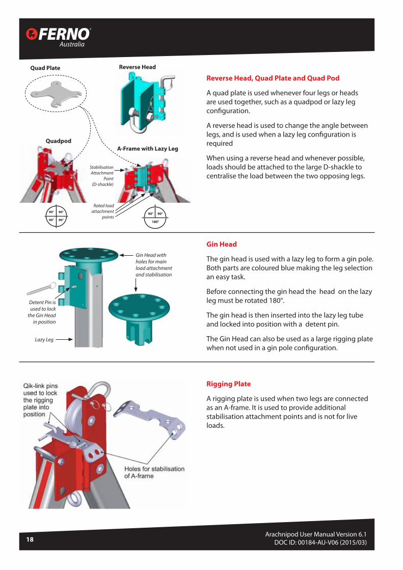
Reverse Head, Quad Plate and Quad Pod
A quad plate is used whenever four legs or heads are used together, such as a quadpod or lazy leg configuration.
A reverse head is used to change the angle between legs, and is used when a lazy leg configuration is required
When using a reverse head and whenever possible, loads should be attached to the large D-shackle to centralise the load between the two opposing legs.
Gin Head
The gin head is used with a lazy leg to form a gin pole. Both parts are coloured blue making the leg selection an easy task.
Before connecting the gin head the head on the lazy leg must be rotated 180°.
The gin head is then inserted into the lazy leg tube and locked into position with a detent pin.
The Gin Head can also be used as a large rigging plate when not used in a gin pole configuration.
Rigging Plate
A rigging plate is used when two legs are connected as an A-frame. It is used to provide additional stabilisation attachment points and is not for live loads.
Quad Plate
Quadpod
Reverse Head
A-Frame with Lazy Leg
Stabilisation Attachment
Point (D-shackle)
Rated load attachment
points
Lazy Leg
Gin Head with holes for main load attachment and stabilisation
Detent Pin is used to lock
the Gin Head in position
90° 90°
90° 90°
90° 90°
180°

19
Arachnipod User ManualVersion 6.0
© Copyright: FERNO AUSTRALIA
Leg with a Standard Foot
All legs have three telescopic sections that are locked with two leg pins. The foot options are held to the base of the lower leg with a detent pin.
A standard foot is ideal for flat surface applications. Lashing holes in the standard foot are provided for the leg restraint rope or other lashing technique.
Unused lower leg holes can also be used with the leg restraint rope or for other lashing techniques.
Spike Foot & Soft Ground Shoe
A spike foot can be used for point loading and ground penetration applications. A stainless steel tip has been added to extend the service life of the spike foot. The spike foot inserts into the foot socket and is held in place with a detent pin.
The soft ground shoe fits over the spike foot and clips to the foot socket. It is used to limit ground penetration in soft ground applications.
Lashing holes
Detent Pin
Hold Down Stake
A hold down stake can be used to secure a standard oot to the ground. The foot locating spike lines up with one of the holes in a standard foot.
Taking care not to impact against the Arachnipod foot or leg, hammer the hold down stake half way into the ground. Check the alignment of the foot locating spike then continue to hammer the stake into the ground. A soft faced or shot filled hammer is recommended for this task.
Maintain the alignment of the foot locating spike and the hole in the standard foot whilst hammering the hold down stake into position.
The hole in the standard foot can also be used to fix the foot using a 12 mm bolt.
Leg Pin
Threetelescopicleg sections
Standard foot
Australia
20Arachnipod User Manual Version 6.1
DOC ID: 00184-AU-V06 (2015/03)
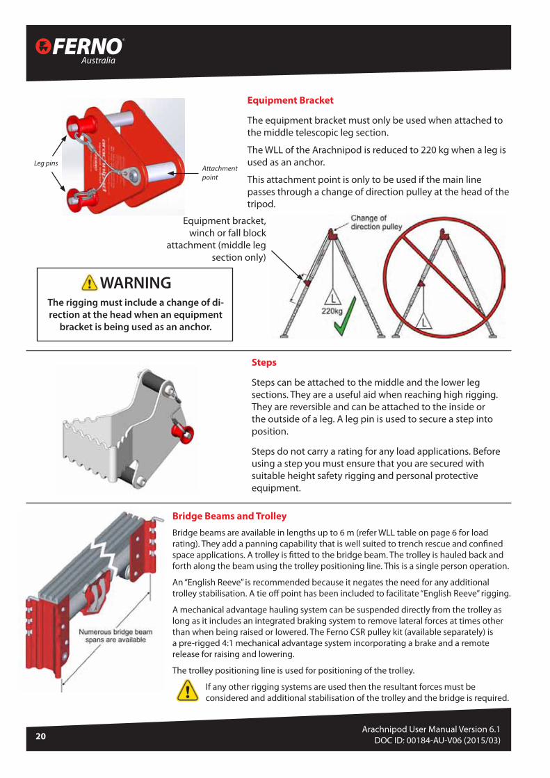
Equipment Bracket
The equipment bracket must only be used when attached to the middle telescopic leg section.
The WLL of the Arachnipod is reduced to 220 kg when a leg is used as an anchor.
This attachment point is only to be used if the main line passes through a change of direction pulley at the head of the tripod.
Steps
Steps can be attached to the middle and the lower leg sections. They are a useful aid when reaching high rigging. They are reversible and can be attached to the inside or the outside of a leg. A leg pin is used to secure a step into position.
Steps do not carry a rating for any load applications. Before using a step you must ensure that you are secured with suitable height safety rigging and personal protective equipment.
Leg pinsAttachment point
Bridge Beams and Trolley
Bridge beams are available in lengths up to 6 m (refer WLL table on page 6 for load rating). They add a panning capability that is well suited to trench rescue and confined space applications. A trolley is fitted to the bridge beam. The trolley is hauled back and forth along the beam using the trolley positioning line. This is a single person operation.
An “English Reeve” is recommended because it negates the need for any additional trolley stabilisation. A tie off point has been included to facilitate “English Reeve” rigging.
A mechanical advantage hauling system can be suspended directly from the trolley as long as it includes an integrated braking system to remove lateral forces at times other than when being raised or lowered. The Ferno CSR pulley kit (available separately) is a pre-rigged 4:1 mechanical advantage system incorporating a brake and a remote release for raising and lowering.
The trolley positioning line is used for positioning of the trolley.
If any other rigging systems are used then the resultant forces must be considered and additional stabilisation of the trolley and the bridge is required.
Equipment bracket, winch or fall block
attachment (middle leg section only)
WARNINGThe rigging must include a change of di-rection at the head when an equipment
bracket is being used as an anchor.

21
Arachnipod User ManualVersion 6.0
© Copyright: FERNO AUSTRALIA
Bridge Systems
A bridge with ‘English Reeve’ rigging
A bridge with a mechanical advantage hauling / lowering system and an integrated brake
Australia
22Arachnipod User Manual Version 6.1
DOC ID: 00184-AU-V06 (2015/03)
Arachnipod Assembly
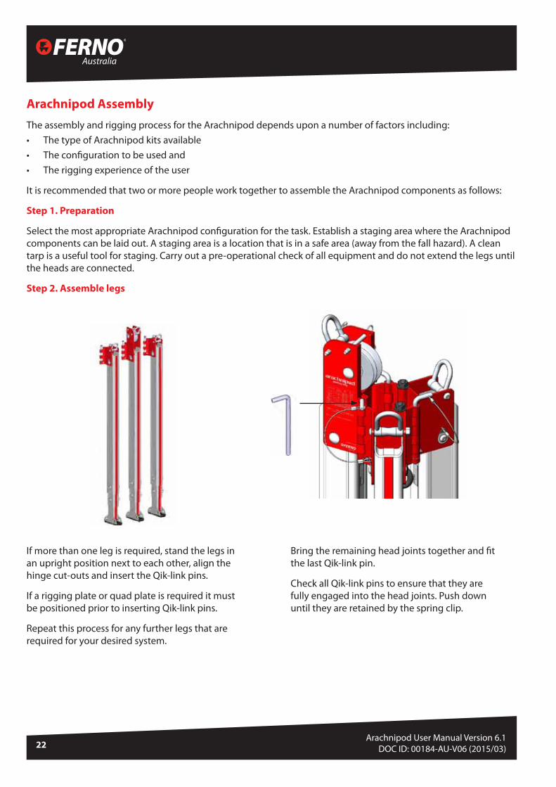
The assembly and rigging process for the Arachnipod depends upon a number of factors including:• The type of Arachnipod kits available• The configuration to be used and• The rigging experience of the user
It is recommended that two or more people work together to assemble the Arachnipod components as follows:
Step 1. Preparation
Select the most appropriate Arachnipod configuration for the task. Establish a staging area where the Arachnipod components can be laid out. A staging area is a location that is in a safe area (away from the fall hazard). A clean tarp is a useful tool for staging. Carry out a pre-operational check of all equipment and do not extend the legs until the heads are connected.
Step 2. Assemble legs
If more than one leg is required, stand the legs in an upright position next to each other, align the hinge cut-outs and insert the Qik-link pins.
If a rigging plate or quad plate is required it must be positioned prior to inserting Qik-link pins.
Repeat this process for any further legs that are required for your desired system.
Bring the remaining head joints together and fit the last Qik-link pin.
Check all Qik-link pins to ensure that they are fully engaged into the head joints. Push down until they are retained by the spring clip.

23
Arachnipod User ManualVersion 6.0
© Copyright: FERNO AUSTRALIA
Bring the remaining head joints together and fit the last Qik-link pin.
Check all Qik-link pins to ensure that they are fully engaged into the head joints. Push down until they are retained by the spring clip.
If a bridge is being used, it can be connected to two sets of A-Frames at this time.
A fourth leg and quad plate can be added to create a quadpod. A reverse head and a quad plate can be added to change the angle between two legs to 180°.
A reverse head and a quad plate must always be used for an A-frame with lazy leg. A quad plate must always be used for a quadpod.
Tripod
Bridge
Quadpod A-Frame with Lazy Leg
120°
120° 120°
120°
120° 120°
90° 90°
90° 90°
90° 90°
180°

Australia
24Arachnipod User Manual Version 6.1
DOC ID: 00184-AU-V06 (2015/03)
Step 4. Extend the legs
Extending the legs can be achieved by removing both leg pins from the legs and adjusting the legs to the desired height. This can be achieved by one person moving from leg to leg and making small adjustments or with multiple persons all adjusting their respective leg simultaneously.
It is easier to adjust the height of the legs whilst they are close together, before splaying them out.
Once desired height is achieved, fit leg pins through leg pin holes. It may be necessary to adjust some or all legs at different heights to suit the terrain. Ferno does not place a limit on the amount of differential adjustment between each leg.
Ensure that the stability of the Arachnipod is maintained whilst the legs are being adjusted.
Check that all leg locking pins are fully engaged.
WARNINGTake care with sliding parts. Do not place fingers into holes and watch for pinch points that may be created depending upon the application and the equipment used.
A rigging plate is recommended for use with an A-frame to provide additional stabilisation of the unit during use.
CAUTIONDouble check ALL connections before proceeding to the next step.
A-Frame
Rigging Plate
Leg pin holes
Step 3. Tether the Arachnipod and move it into position
Tethering is not to be confused with stabilisation. Tethering simply stops the equipment from being dropped over an edge whereas stabilisation stops unwanted movement whilst the equipment is being used.
Tether the Arachnipod with a rope to prevent it from being dropped over an edge.
Once the Arachnipod has been tethered it can be moved into position.
Leg pin
Do not place fingers into leg pin holes

25
Arachnipod User ManualVersion 6.0
© Copyright: FERNO AUSTRALIA
Step 6. Secure the legs
Secure the legs to suit the application.
A length of rope and a rope grab can be used to stop the legs from splaying.
Legs may also be lashed into position or some foot options may provide sufficient leg stability without additional rigging.
CAUTIONLegs must be prevented from splaying apart when loaded. Damage to the Arachnipod may result if the splaying of legs is not managed.
Step 5. Position the legs
Check that the legs are positioned in a secure location and ensure that the most appropriate foot option is being used.
Step 7. Assess the resultant force and direction
Tension and pre-load lines may need to be rigged to ensure Arachnipod stability. Please read the section in this manual titled “Assessing the stability of your Arachnipod rigging”. Using hand tension, a simulated force can be applied by to the main line to visualise the resultant direction. The positioning of the head and the length of the legs can now be modified so that the resultant direction is located appropriately.
Step 8. Provide additional rigging as required
Add additional tension and pre-load rigging as necessary to ensure stability. Apply tension to all stabilisation rigging as required, then check the Arachnipod for stability.
Step 9. Rig a two rope system wherever possible
Rig a two-rope system to provide a backup to both the main line and the edge management rigging.
Step 10. Carry out a safety check
Visually check all anchors, rigging, karabiners, friction devices, harnesses and personal protective equipment before committing anyone to the edge. Edge safety lines must be provided for any persons who are working close to the edge.
Step 11. Weight the system and recheck the resultant
Before committing a load to the edge, the system should be weighted in a safe manner (for example: backed up with a safety line) and the resultant re-checked. This step should be carried out in a manner that allows retrieval of the load if adjustments to the configuration or rigging are needed.
Step 12. Monitor the Arachnipod for stability
There are many factors that can change the physics of the edge management task and as such the stability of the Arachnipod must be constantly monitored. If any instability is detected then the safety line can be set to safely hold the load whilst adjustments are made.

Australia
26Arachnipod User Manual Version 6.1
DOC ID: 00184-AU-V06 (2015/03)
Using an Arachnipod leg as an anchor
The Arachnipod equipment bracket can be used to provide a rated attachment point that connects to a leg of the Arachnipod. Anchoring to a leg is useful in many situations including tripod applications. The WLL is reduced to 220kg when a leg is used as an anchor. The equipment bracket is designed to be attached to the middle telescopic leg.
WARNING The rigging must include a change of direction at the head when an equipment bracket, winch or fall block is being used as an anchor.
Anchoring the Arachnipod
The number of anchors that will be required depends entirely upon the configuration of the Arachnipod.
Safe and secure anchors will be required for:1. The main line2. The safety line3. Edge safety lines (for persons working close to an edge)4. The initial rope lanyard or tether used to secure the Arachnipod.5. Each tension line and6. Each pre-load line
Anchor selection and anchor rigging techniques are not within the scope of this manual.
Equipment bracket, winch or fall block
attachment (middle leg section only)
STABILISATION

27
Arachnipod User ManualVersion 6.0
© Copyright: FERNO AUSTRALIA
Tripod Stabilisation
This tripod application does not require any additional rigging because the resultant force and direction is within the triangular base.
The dotted lines on the ground surface represent the point where the resultant direction is focused.
This tripod application requires additional rigging to counteract or balance the resultant force and direction.
The dotted lines on the ground surface represent the point where the resultant direction is focused
Equipment bracket or winch used as an anchor

Australia
28Arachnipod User Manual Version 6.1
DOC ID: 00184-AU-V06 (2015/03)
Lazy Leg Tripod Stabilisation
A lazy leg or easel leg tripod is similar to a regular tripod because it uses three legs in compression. A lazy leg tripod is constructed as an A-frame with an additional leg known as the lazy leg. The angle and length of the lazy leg is set so that the resultant force and direction can be managed.
Some lazy leg tripods will require additional rigging to provide sufficient stabilisation and security.
If a lazy leg tripod is rigged so that the resultant force and direction is being applied downwards and within the triangular base then the lazy leg tripod will remain stable. If the load shifts closer to any given leg then the load being applied to that leg increases but the tripod will remain stable.
The dotted lines on the ground surface represent the point where the resultant direction is focused.
If the resultant force and direction is being applied outside of the triangular base then the lazy leg tripod will become unstable.
Additional rigging will be required to provide lazy leg tripod security.
The length and position of the lazy leg may be adjusted to assist with the management of the resultant direction.
The dotted lines on the ground surface represent the point where the resultant direction is focused.

29
Arachnipod User ManualVersion 6.0
© Copyright: FERNO AUSTRALIA
Quadpod Stabilisation
The Quadpod allows for greater versatility and stability combining 4 legs into one system.
A Quad Plate is required to ensure stability of the entire system. The principles of stabilisation are the same as a Tripod with the addition of an extra leg.
This Quadpod application does not require any additional rigging because the resultant force and direction is within the triangular base.
The dotted lines on the ground surface represent the point where the resultant direction is focused.
This Quadpod application does not require any additional rigging because the resultant force and direction is within the triangular base.
The dotted lines on the ground surface represent the point where the resultant direction is focused.
Independent object used as an anchor
Tension rigging used to stabilise
= Tension rigging= Pre-load rigging

Australia
30Arachnipod User Manual Version 6.1
DOC ID: 00184-AU-V06 (2015/03)
A-Frame Stabilisation
An A-frame makes use of two legs to form two compression members. A-frames always require rigging to provide at least one tension member, additional rigging can be used to provide two or more tensioned members and pre-load rigging can be used to hold the A-frame in position. A-frames can be constructed with Arachnipod components using three methods:
Method 1 Standard A-frame
Two legs positioned perpendicular to the load line. Tension and pre-load rigging is used to hold the A-frame in position.
This method is ideal for holding span lines off an edge.
Method 2 Sideways A-frame (SA-frame)
Two legs positioned close to parallel with the load line. The leg lengths and positions are set so that the resultant direction is focused between the two legs but not in direct alignment with the legs.
The SA-frame is tilted to ensure that the resultant direction remains focused at a point that is offset from the alignment of the legs. The dotted lines on the ground surface represent the point where the resultant direction is focused. If the tilt is offset to the right then the tension rigging will need to be on the left. If the tilt is offset to the left then the tension rigging will need to be on the right.
The feet will need to be securely located or lashed into position to resist lateral movement. All rigging should be adjustable so that tensions can be modified as required.

31
Arachnipod User ManualVersion 6.0
© Copyright: FERNO AUSTRALIA
SA Frame: front elevation view SA Frame: plan view
When rigging an SA-frame, the resultant forces are being applied downwards and balanced mostly by the A-frame legs (front elevation). The SA-frame should be laid over, tilted or offset slightly for the following two reasons:
1. To provide clearance so that the main line does not contact the Arachnipod components, and
2. To ensure that the rigging is clearly identified as being “tension rigging” and “preload rigging”
The tension rigging keeps the A-frame in position and balances out resultant forces created by the lay or offset positioning of the SA-frame whereas the preload rigging is used to preload the SA-frame and hold it firmly against the ground.
The load upon the tension rigging increases as the offset is increased. Sufficient offset is required to ensure that the tension rigging remains in tension with consideration to any changes in load force direction during the operation. Avoid excessive offset because this places unnecessary force upon the tension rigging.
Australia
32Arachnipod User Manual Version 6.1
DOC ID: 00184-AU-V06 (2015/03)
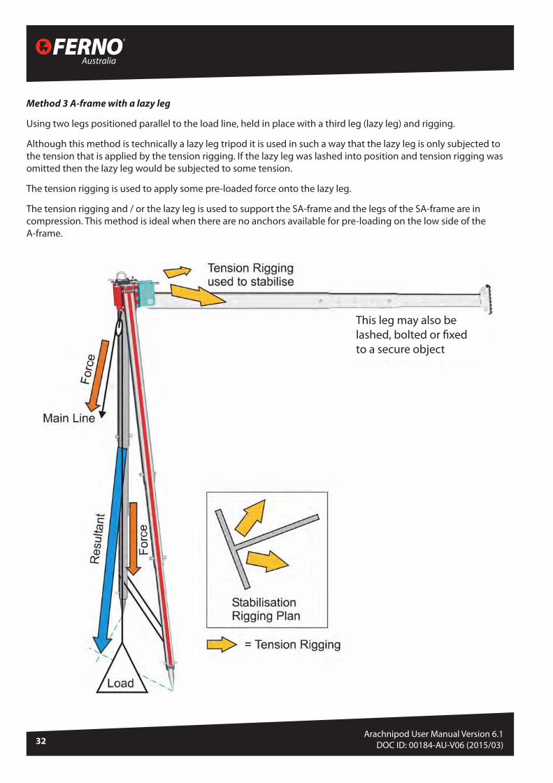
Method 3 A-frame with a lazy leg
Using two legs positioned parallel to the load line, held in place with a third leg (lazy leg) and rigging.
Although this method is technically a lazy leg tripod it is used in such a way that the lazy leg is only subjected to the tension that is applied by the tension rigging. If the lazy leg was lashed into position and tension rigging was omitted then the lazy leg would be subjected to some tension.
The tension rigging is used to apply some pre-loaded force onto the lazy leg.
The tension rigging and / or the lazy leg is used to support the SA-frame and the legs of the SA-frame are in compression. This method is ideal when there are no anchors available for pre-loading on the low side of the A-frame.
This leg may also be lashed, bolted or fixed to a secure object

33
Arachnipod User ManualVersion 6.0
© Copyright: FERNO AUSTRALIA
Gin Pole Stabilisation
A gin pole (monopole / monopod) makes use of a single leg to form the compression member. Gin poles always require rigging to provide at least two tension members, additional rigging can be used to provide three or more tensioned members and one or more pre-load members to hold the gin pole into position.
A gin pole is positioned and rigged so that the resultant forces are being applied close to the long axis of the single leg with a slight offset for two reasons:
1. To provide clearance so that the main line does not contact the Arachnipod leg, and
2. To ensure that the tension and pre-load rigging is clearly identified
The tension rigging keeps the gin pole in position and balances out any resultant forces created by the slight offset nd the preload rigging keeps the gin pole in position.
Gin Pole: front elevation view Gin Pole: plan view

Australia
34Arachnipod User Manual Version 6.1
DOC ID: 00184-AU-V06 (2015/03)
Using a single leg to manage a handrail
A single leg can be used to form a compression member that will help support a handrail. If the resultant direction is focused at a point that is just forward of the foot then most of the force will be transferred to the ground by the leg.
WARNINGThis technique is recommended for advanced users only; incorrect use of this system could be dangerous. An assessment of the handrail is required to ensure that it is suitable for this type of rigging. The angle of the leg and the resultant direction must be considered when assessing the handrail
Additional rigging used to stabilise
Independent object used as the main line anchor
Leg securing ropes or round lashing can be used to provide tension rigging that keeps the single leg in place. Square lashing can be used to secure the leg to the hand rail.

35
Arachnipod User ManualVersion 6.0
© Copyright: FERNO AUSTRALIA
Bridge Stabilisation
A bridge makes use of four legs that are all in compression and a bridge beam that spans between two sets of two legs.
Additional rigging must be used to increase the stability of the bridge
Additional security must be used for the feet to prevent movement as shown
Additional rigging must be used to increase the stability of the bridge
If a bridge is rigged in such a way that resultant force and direction remain within the rectangular base then the bridge will remain stable. The strength of the bridge beam and the four legs balances the resultant force. If the load shifts closer to any given leg then the load being applied to that leg is increased but the bridge will remain stable.
Additional rigging must be used to protect against any unplanned shifts in resultant direction. Instability will occur if the resultant direction moves outside of the rectangular base. Always consider the stability of the feet regardless of the configuration being used.
CAUTIONEvery change of line direction will create a resultant direction. In this example (above) the resultant below the load is directly relating to the stability of the bridge. A Bridge Ratchet Strap Stabilisation Kit is available as an optional extra (refer later in this manual)
Equipment bracket can be used as an anchor if required
Adjust trolley position

Australia
36Arachnipod User Manual Version 6.1
DOC ID: 00184-AU-V06 (2015/03)
ACCESSORIESFoot Options for your Arachnipod
Standard Foot
A polyurethane tread molded around an aluminium foot. The standard foot is ideal for flat surface applications
Spike Foot
A pointed aluminium spike with a replaceable stainless steel tip. The spike foot is ideal for point loading and ground penetration applications.
Soft Ground Shoe
A hard polyurethane disc that is used in conjunction with the spike foot to limit ground penetration in soft ground applications.
Hold Down Stakes
A steel picket with an impact plate and a locating pin. The steel picket is driven into the ground after aligning the locating pin with a hole in a standard foot. This secures the foot to the ground.
Tru-bolts
Tru-bolts are supplied in the accessory kit. Tru-bolts can be used in place of hold down stakes to secure the foot to concrete and other hard rock surfaces.

37
Arachnipod User ManualVersion 6.0
© Copyright: FERNO AUSTRALIA
Additional Accessories for your Arachnipod
(All sold separately)
APOD-W20Winch with 20m cable
APOD-EKLLExtension kit for Lazy Leg
APOD-FAFall Arrest Block with Retrieval Winch
APOD-BRSBridge Ratchet Strap Kit
APOD-LLALazy Leg Adaptor
Winch with bracket to mount to middle section of any supporting leg. WLL 220 kg / 485 lb
Extends the length of Lazy Leg by 1.7 m / 67”
Fall arrest block with bracket to mount to middle section of any supporting leg WLL 136 kg/ 300 lb
Stabilises the Arachnipod system
Converts a Lazy Leg into a Standard Leg

Australia
38Arachnipod User Manual Version 6.1
DOC ID: 00184-AU-V06 (2015/03)
WINCH - INSTRUCTIONS
Pulley head in use
Edge protection
Change of direction pulley in use

39
Arachnipod User ManualVersion 6.0
© Copyright: FERNO AUSTRALIA
ISC UB171 FALL ARREST ADAPTOR BRACKET - INSTRUCTIONSThis bracket is CE certfied to CEN/TS 16415:2013 and EN795:12

Australia
40Arachnipod User Manual Version 6.1
DOC ID: 00184-AU-V06 (2015/03)
Lazy Leg Extension Kit Instruction Sheet
Both the Lazy Leg Extender Head and the Lazy Leg ExtenderPlate Assembly must be used together.
The Lazy Leg Extension Kit provides bracing support only andmust be used to extend any structural components.
All the Qik-link pins, leg pins and the detent pin must beused to ensure that the lazy leg and the additional
standard leg are properly supported.
NOT
Lazy Leg Extender Head
Support / Bracing
Load
Lazy Leg Extender Plate Assembly
Lazy LegStandard Leg
Hinge styleattachmentsfor theadditionalstandard leg
Remove foot - use detent pin
Leg pin
Leg pin
Plastic keeper toretain the Qik-link pinsQik-link pin
Qik-link pin
Assembly Guide
Attach the “Lazy Leg ExtenderHead” to the lazy leg
Secure with 2x leg pins
Remove the lazy leg foot (retainthe detent pin)
Attach the “Lazy Leg PlateAssembly” to the lazy Leg
Secure with:1x leg pin and the lazy leg detentpin
Attach the extra “Standard Leg”
Secure with:2x Qik-link pins and2x Leg pins
Check that the Qik-link pins areclipped into the moulded plastickeeper to ensure pin security
1.
2.
3.
4.
A lazy leg is used to provide additional bracing support to an “A”frame, it can act as both a tension or compression member. Itdoes provide the structural strength of the configuration.
The “Lazy Leg Extension Kit” includes two components that areused to attach an additional standard leg to the lazy leg to providegreater reach.
NOT
Stre
ngth
WARNING
Leg pin
Leg pinLeg pin
Lazy leg foot detentpin used here
FERNO AUSTRALIA11 Johnstone Road, Brendale, Queensland 4500, T: +61 7 3881 4999 E: [email protected] W: ferno.com.au
LAZY LEG EXTENSION KIT - INSTRUCTIONS

41
Arachnipod User ManualVersion 6.0
© Copyright: FERNO AUSTRALIA
LAZY LEG ADAPTOR PLUG -- INSTRUCTIONS
A Lazy Leg Adaptor Plug is used to convert a lazy leg into a standard leg. It is supplied with a detent pin that is used to secure the Lazy Leg Adaptor Plug into position.
Once fitted to the lazy leg, the Lazy Leg Adaptor Plug provides a stop so the leg can only rotate 25 degrees.
Assembly Guide
NOTE: It is easier to fit the Lazy Leg Adaptor Plug before the lazy leg is attached to any other legs.
1. Remove the detent pin and the stabilisation attachment point (D ring) at the head of
the leg
2. Rotate the leg so that it is positioned parallel to the head
3. Remove the detent pin from the Lazy Leg Adaptor and insert the
Lazy Leg Adaptor Plug in the top of the leg
4. Insert the detent pin through the accessory attachment
hole to secure the Lazy Leg Adaptor Plug
5. Refit the stabilisation attachment point (D
Ring)
6. Add the leg to desired
configuration eg Tripod
WARNING:Legs must be prevented from splaying apart when loaded. Damage to the Arachnipod may result if the legs are not properly secured. Refer to Step 6: Securing the Legs in Arachnipod Assembly section.
Lazy Leg Adaptor Plug Detent Pin
Detent Pins
Head
Parallel
Parallel
Lazy Leg(top section)
Stabilisation Attachment
Point (D Ring)

Australia
42Arachnipod User Manual Version 6.1
DOC ID: 00184-AU-V06 (2015/03)
EQUIPMENT BRACKET WITH 2:1 RIGGING - INSTRUCTIONS

43
Arachnipod User ManualVersion 6.0
© Copyright: FERNO AUSTRALIA
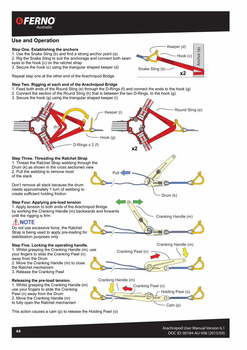
BRIDGE RATCHET STRAP KIT (APOD BRS) - INSTRUCTIONS
Australia
44Arachnipod User Manual Version 6.1
DOC ID: 00184-AU-V06 (2015/03)

45
Arachnipod User ManualVersion 6.0
© Copyright: FERNO AUSTRALIA
INSPECTION MANUAL
Arachnipod Inspection
ArachnipodInspection

Australia
46Arachnipod User Manual Version 6.1
DOC ID: 00184-AU-V06 (2015/03)
INSPECTION MANUAL
IMPORTANT
If the stoppers are missing or do not work, the leg sections can sepa-rate completely from one another. Any legs with missing or damaged stoppers must be returned to Ferno or an authorised repair agent for repair.
ARACHNIPOD RED LEG LABELS - set of 3 #51-0058
ARACHNIPOD LABEL - Re-flectve Silver #51-0050
Fig 3
Fig 4
Leg pin holes
Leg pin
DO NOT place fingersinto leg pin holes
Fig 4
ARACHNIPOD DISASSEMBLYThe disassembly and rigging process for the Arachnipod depends upon a number of factors including:• The type of Arachnipod kit• The configuration that is used.
It is recommend that two or more people work together to disassemble the Arachnipod components as follows:
Step 1: Preparation
• Establish a working area where the Arachnipod components can be laid out• A working area is a location that is safe, away from fall, slip and other haz-
ards that would impede the inspection process• A clean tarp or work area is beneficial for the inspection process
Step 2: legs
• Remove the Arachnipod from the storage bag (if supplied) • Lay the unit down on the work/ inspection area• Remove the Qik-Link pins from each of the heads (Fig 3)• Repeat this process for any other legs to ensure all the legs are independent
to each other
LEG INSPECTIONExtend and Inspection of Legs and Pins
1. Remove both leg pins from the legs and extend the legs to their maximum extension. During the process of extending the legs, ensure the legs move smoothly without any snagging.
2. When legs are at maximum extension, ensure the legs do not come apart and are stopped by the internal leg stopper.
3. Inspect the legs for damage, deep gouging, deformation and straightness. If there are any signs of bending, deformation or deep gouging the leg must be replaced.
4. Check each leg pin hole on the leg (Fig 4), looking for lower deep indenta-tions on the pin area. If deep (more than 0.5mm) indents re evident, this may be an indication that the leg has been subjected to overloading and should be removed from service.
Leg Pin Assembly Inspection
1. Inspect the leg pin holes (Fig 4) and ensure there is no deformation, deep gouging or obvious damage.
2. Inspect the leg pin (Fig 5) ensuring smooth operation. When button is de-pressed, small ball stoppers on other end of pin should release.
3. Inspect the cable that attaches the leg pin to the leg. If the cable is dam-aged, replace the cable accordingly.
CABLE, 150mm with rings #91-0004 ARACHNIPOD BALL LOCK LEG PIN #68-0054
LabelsRed labels are adhered to the outside face of each leg. The middle and lower leg have alpha and numeric markings at each hole position to allow all legs to be easily set to the same height (eg B-3). Check all labels are present and legible. Replace any damaged labels.

47
Arachnipod User ManualVersion 6.0
© Copyright: FERNO AUSTRALIA
INSPECTION MANUAL
INSPECTING THE HEADS OF EACH LEGStandard Leg (Fig 5)
1. Remove the Qik Link pin from the leg and inspect the pin for any dam-age or deformation. Inspect the cable on the Qik Link pin that holds the pin on to the head for damage. In the event of damage or deformation, replace cable with:
CABLE, 250mm with rings #91-0005 ARACHNIPOD QIK LINK Head Pin #22-1002
2. Inspect the attachment points (cutouts) and ensure they are not dam-aged and that the Qik Link pin inserts easily into the cutouts. Ensure the Qik Link pin locks into the spring keeper and that the Qik Link pin is held firmly into place once inserted into the head attachment point.
3. Inspect the rated load attachment point (eyebolt) and ensure it can swivel 360˚ and that the top holding nut weld is intact and has not been tampered with. Ensure the eye is not deformed and there is no evidence that the attachment point has been overloaded. In the event of overload-ing or deformation the leg must be permanently removed from service.
4. Inspect Stabilisation Attachment Point (D-shackle) for deformation or damage. In the event of deformation or damage, replace the D-shackle. D-SHACKLE with hardware #91-0006
5. Ensure head moves and swivels easily on the leg and there is no binding up of the movement.
6. Ensure the Head/ Leg bolt is tight and secure. If the head/ leg connect-ing bolt is loose, remove the bolt and apply Loctite® 7262 thread lock-ing compound to the threads and retighten the bolt. Be careful not to cross-thread the bolts as the product will become unsafe, dramatically reduce the WLL and be dangerous to use. If cross threaded, the unit must be sent back to Ferno Australia.
7. Inspect the entire head for damage and indentations. Normal wear and tear is acceptable. However if obvious damage is noticeable, return to Ferno or an authorised agent for repair or replace the entire leg unit.
8. Inspect the load rating labels on either the head or leg and ensure all the information is legible.
Pulley Leg (Fig 6)
1. Follow all the inspection procedures as laid down for the Standard Leg.
2. Inspect the pulley and ensure that the pulley rotates freely and there is no binding up or resistance on the bearings of the pulley. Inspect the grooves of the pulley and ensure there is no damage or sharp edges within the sheave.
3. Ensure the two detent pins are fully operational and insert easily into the holes of the head. If they show signs of rust, lubricate with a Teflon based spray lubricant. The pulley has been designed to accommodate up to 13mm fibre rope as well as up to 8mm steel/stainless steel wire rope cable.
4. The stabilisation attachment point (D-shackle) is removable. It is attached with the two detent pins via a cable. Ensure the cable is intact and free from damage. If any parts are damaged, replace with the following parts:
D-shackle on cable, with ring #90-0007 SS Detent Pin - 3/8” dia x 3” #68-0036
Qik Link pin
Rated load attach-ment point with built-in swivel (eyebolt)
Attachment point foradditional legs
Head/Leg connecting bolt
Stabilisation Attachment point (D-shackle)
Attachment point for additional legs
Detent pins are used to prevent ropes or cable from escaping the pulley grooves
Removable stabilisation attachment point
Double groove pulley accom-modates up to 13mm fibre rope and 8mm wire rope cable
Fig 5
Fig 6

Australia
48Arachnipod User Manual Version 6.1
DOC ID: 00184-AU-V06 (2015/03)
INSPECTION MANUAL
Lazy Leg (Fig 7)
1. Follow all the inspection procedures as laid down for the Standard Leg.
2. The Lazy Leg is coloured blue for easy identification. It has a pivot range of 180˚. Remove the Detent Pin and Stabilisation Attachment Point (D-shackle) from the head. If a Lazy Leg Adaptor is present, remove it. Refer to Arachnipod Operators’ Instructions regarding the Lazy Leg Adaptor application and use.
3. Ensure the Lazy Leg Head can pivot 180˚ and that there is no binding up or stiffness in the pivot action.
4. The stabilisation attachment point (D-shackle) is removable. It is at-tached with the Detent Pin via a cable. Ensure the cable is intact and free from damage. If any parts are damaged, replace with the follow-ing parts:
D-SHACKLE on cable, with ring #90-0007 SS DETENT PIN 3/8” dia x 3” #68-0036 ARACHNIPOD QIK LINK Head Pin #22-1002
FOOT INSPECTIONStandard Feet (Fig 8)
Standard feet are supplied with all legs.
1. Remove the Detent Pin from the leg and inspect the Detent Pin and cable attachment. Replace the cable if it is damaged with part:
CABLE, 150mm with rings #91-0004 SS Detent Pin - 3/8” dia x 2.5” #68-0035
2. Inspect the foot ensuring the polyurethane plastic tread is not dam-aged.
3. Inspect the foot and lashing holes for deformation, damage and sharp edges. If any of these are evident, replace the foot with part:
ARACHNIPOD FOOT, with tread #07-1024-0
Spike Foot (Fig 9)
A Spike Foot can be used for point loading and ground penetration appli-cations. A stainless steel tip has been incorporated to extend the service life of the Spike Foot. The Spike Foot inserts in to the foot socket on the leg end and is held in place with a Detent Pin.
1. Inspect the Spike Foot fo deformation, damage and sharp edges. If the Spike Foot’s stainless steel tip is deformed and damaged, it can be replaced by unscrewing the tip and replacing it with a new tip. SPIKE FOOT TIP #22-1004; SPIKE FOOT with tip #90-0120 Prior to insert-ing the new tip, place Loctite® 7262 thread-locking compound on to the thread and then tighten.
2. Insert the Spike Foot into the foot socket on the leg, ensuring the Spike Foot slides smoothly into the socket. Align the Spike Foot Detent Pin hole and insert the Detent Pin through these holes. The insertion and locking process should be smooth and easy.
3. Remove the Detent Pin and Spike Foot from the leg and repeat this process for all the Spike feet.
Qik Link pin
Attachment point for additional legs
Lazy leg pivots 180˚
Detent Pin is used for the removable stabilisation at-tachment point as well as the lock when using the Lazy Leg with the Gin Head
Fig 7
Fig 9
Fig 8
Lashing holes
Standard Foot
Detent pin
Spike Foot
Soft ground shoe
Detent pin
Foot socket
Stainless Steel tip
49
Arachnipod User ManualVersion 6.0
© Copyright: FERNO AUSTRALIA
INSPECTION MANUAL
Detent pin
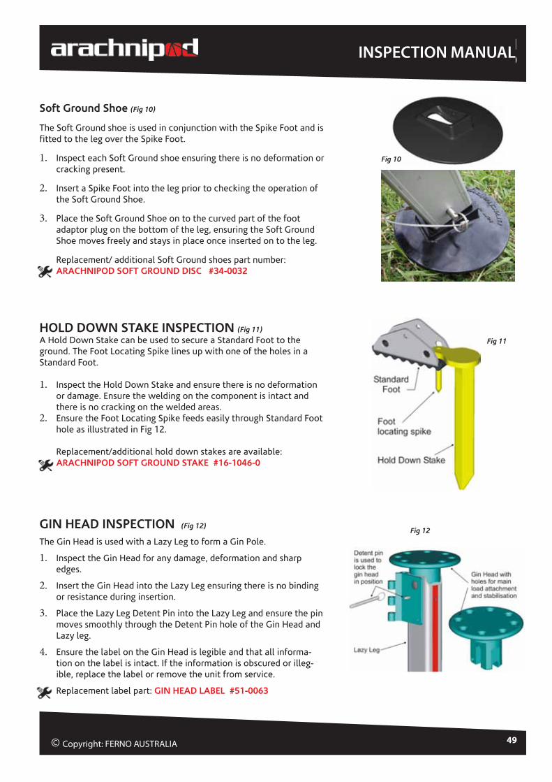
Soft Ground Shoe (Fig 10)
The Soft Ground shoe is used in conjunction with the Spike Foot and is fitted to the leg over the Spike Foot.
1. Inspect each Soft Ground shoe ensuring there is no deformation or cracking present.
2. Insert a Spike Foot into the leg prior to checking the operation of the Soft Ground Shoe.
3. Place the Soft Ground Shoe on to the curved part of the foot adaptor plug on the bottom of the leg, ensuring the Soft Ground Shoe moves freely and stays in place once inserted on to the leg.
Replacement/ additional Soft Ground shoes part number: ARACHNIPOD SOFT GROUND DISC #34-0032
HOLD DOWN STAKE INSPECTION (Fig 11)
A Hold Down Stake can be used to secure a Standard Foot to the ground. The Foot Locating Spike lines up with one of the holes in a Standard Foot.
1. Inspect the Hold Down Stake and ensure there is no deformation or damage. Ensure the welding on the component is intact and there is no cracking on the welded areas.
2. Ensure the Foot Locating Spike feeds easily through Standard Foot hole as illustrated in Fig 12.
Replacement/additional hold down stakes are available: ARACHNIPOD SOFT GROUND STAKE #16-1046-0
GIN HEAD INSPECTION (Fig 12)
The Gin Head is used with a Lazy Leg to form a Gin Pole.
1. Inspect the Gin Head for any damage, deformation and sharp edges.
2. Insert the Gin Head into the Lazy Leg ensuring there is no binding or resistance during insertion.
3. Place the Lazy Leg Detent Pin into the Lazy Leg and ensure the pin moves smoothly through the Detent Pin hole of the Gin Head and Lazy leg.
4. Ensure the label on the Gin Head is legible and that all informa-tion on the label is intact. If the information is obscured or illeg-ible, replace the label or remove the unit from service.
Replacement label part: GIN HEAD LABEL #51-0063
Fig 10
Fig 11
Fig 12

Australia
50Arachnipod User Manual Version 6.1
DOC ID: 00184-AU-V06 (2015/03)
INSPECTION MANUAL
RIGGING PLATE INSPECTION (Fig 13 )
A rigging plate is used when two legs are connected as an A-Frame.
1. Inspect Rigging Plate and ensure there is no deformation, damage or sharp edges.
Replacement/additional rigging plates are available: ARACHNIPOD RIGGING PLATE #26-0007-0
EQUIPMENT BRACKET (Fig 14)
The Equipment Bracket must only be used when attached to the mid section of the telescopic leg.
1. Remove lynch pins from leg pins to release and remove leg pins from Equipment Bracket.
2. Inspect cables that attach the leg and lynch pins and ensure cables are not damaged. If there is any damage, replace the cables.
3. Ensure the bolts on the attachment point are tight and secure. If either of the bolts are loose, remove the bolt and apply Loctite® 7262 thread locking compound to the threads and re-tighten the bolt. Be careful not to cross-thread the bolts as the product will become unsafe, dramatically reduce the WLL and be dangerous to use. If cross threaded, the unit must be sent back to Ferno Australia.
4. Ensure the label on the Equipment Bracket is readable and that no writing/ information is obscured. If there is damage to the label, replace it.
EQUIPMENT BRACKET LABEL #51-0064 CABLE, 150mm with rings #91-0004 ARACHNIPOD BALL LOCK Leg Pin #68-0054
REVERSE HEAD (Fig 15)
1. Remove the Qik Link pin from the head and inspect the pin for any dam-age or deformation. Inspect the cable on the Qik Link pin that holds the pin on the head for damage. In the event of damage or deformation, replace cable with:
CABLE, 250mm with rings #91-0005
2. Inspect the attachment points (cutouts) and ensure they are not damaged and that the Qik Link pin inserts easily into the cutouts. Ensure the Qik Link pin locks into the spring keeper and the pin is held firmly into place once inserted into the head attachment point.
3. Inspect the entire head and D-shackle for damage and indentations. Nor-mal wear and tear is acceptable. If obvious damage is noticed, replace the entire unit.
4. Ensure the D-shackle centre bolt is tight and the actual D-shackle pivots freely on the bolt. If the bolt and nut are loose, retighten Nylock nut on the side of the Head.
5. Inspect the load rating label on the Head and ensure all the information is legible.
Fig 13
Qik Link pins used to lock the Rigging Plate into position
Holes for stabilisation rigging of A-Frame
Fig 15
Fig 14
Leg Pins
Attachment Point

51
Arachnipod User ManualVersion 6.0
© Copyright: FERNO AUSTRALIA
INSPECTION MANUAL
BRIDGE BEAM & TROLLEY INSPECTION (Fig 16 )
Bridge Beams are available in lengths up to 6m.
Bridge Beam
1. Lay the Bridge Beam on a flat surface and ensure there is no bend-ing or deformation of the beam. Ensure there are no sharp edges, deep indentations or cracks within the Bridge Beam.
2. Inspect each Head attachment point ensuring the Qik Link pins are aligned and they insert smoothly into the cutout sections. Ensure the Qik Link pins bed securely into Spring Keeper.
3. Ensure all the bolts that hold the head attachment points on to the beam are tight and fastened. If any bolts are loose, re-tighten them.
4. Inspect the Trolley rope. The rope should be tied to the eyebolts on the Bridge Trolley with Yosemite bowline knots. Check the knots are secure and ensure there is no damage, evidence of chemical contamination or abrasion of the rope. If any of these are present, the rope must be replaced. It is important to replace the rope with 8mm kernmantle rope as supplied by Ferno Australia.
5. Inspect the pulleys through which the trolley guide rope runs at each end of the Bridge. Ensure that pulleys move freely and do not bind up. If the bearings need replacing, return the unit to Ferno or an authorised Ferno repair agent.
Bridge Beam Trolley
1. Inspect the Bridge Beam Trolley ensuring here is no deformation, damage or rust on the trolley.
2. Check all the bolts on the Bridge Beam Trolley are fastened and secure.
3. Ensure the Trolley or bearings on the Bridge Beam Trolley are not corroded and that the bearings rotate freely without any resist-ance. If the bearings need replacing, return the unit to Ferno or an authorised Ferno repair agent.
4. Check the trolley has the SWL/ WLL label present. If illegible or missing, replace the label with:
ARACHNIPOD BRIDGE TROLLEY 250kg WLL Label #51-0069
ARACHNIPOD WINCH INSPECTION (Fig 17)
The Winch is supplied with a bracket to mount it to the mid-section of any Arachnipod supporting leg. It is rated to 220kg/ 485lb.
Thorough Inspection of Arachnipod Winch
1. Clean if required and visually inspect the winch and mount bracket for physical damage and chemical contamination.
2. Check for cracks, corrosion, deformation, abrasions and any other damage.
Fig 16
Fig 17

Australia
52Arachnipod User Manual Version 6.1
DOC ID: 00184-AU-V06 (2015/03)
INSPECTION MANUAL
3. Check the label is in good condition and legible. Replace if necessary.
ARACHNIPOD WINCH LABEL #51-0066
NOTE: When replacing a label, the Winch serial number must be transferred to the new label and recorded in the equipment log.
Thorough Inspection of Winch Wire Rope Cable
1. Unwind the drum until the cable is completely unwound.
2. Visually inspect the entire length of the wire rope by passing the wire rope through gloved hands, flexing the cable every few inches to expose any broken strands of wires.
3. Inspect for any degradation or damage. Especially look for cuts, local surface abrasion, signs of chemical contami-nation, corrosion (rust), discolouration and glazing. Special attention should be paid to the wire rope around the swaged eye.
4. The cable has a red indicator to alert users when there is only 1m of cable left on the drum. Check this red heat shrink marker is still present on the cable. It should be approximately 1m from the drum.
5. Ensure wire rope end is securely fastened to the drum of winch. Check that the wire rope is threaded through the hole within the bolt and that the nut is securely fastened.
6. Check there are three (3) wraps of cable secured together with a swage, and that the swage is tight.
7. The cable should be replaced if there are six or more randomly broken wires in one lay, or three or more broken wires in one strand in one lay. If the cable needs replacing, return the complete winch to Ferno or a Ferno authorised repair agent.
Winch Notes
• LAY is a length of wire rope that it takes for one strand to complete one revolution or twist along the cable
• STRAND is a larger group of wires that make up a cable.
• The cable should be replaced if there are any broken wires within 25mm (1”) of the metal swages at either end of the cable.
• The cable assembly should be replaced if the cable is severely kinked, cut, crushed, burnt, corroded or suffering any other type of damage.
Thorough Inspection Function Test
1. Extract 600mm to 1000mm of rope
2. Apply 50kg weight to the rope. The rope should lock off with no slippage.
3. Wind the winch making sure that the gears aren’t slipping.
Lubrication on the Winch
The only lubrication to be used on the winch is an aerosol spray chain lube. This should only be applied to the gears.
BRIDGE BEAM & TROLLEY INSPECTION cont’d

53
Arachnipod User ManualVersion 6.0
© Copyright: FERNO AUSTRALIA
ARACHNIPOD KIT RECORDSEach Arachnipod Kit is assigned a Kit Number. This is one collective number recorded on Ferno Australia’s database, which references all individual serial numbers contained within the Arachnipod kit.
A kit contains more than one item with a serial number. It can be just a tripod, a tripod plus accessories, a Bridge Kit, a full TEMS kit etc. The Kit Number can be found next to the serial number on ONE of the standard legs contained within the kit. Please record this number in the space below along with all the individual serial numbers for your own reference. Additional copies of this form can be downloaded from Ferno’s website: www.ferno.com.au
KIT NUMBER: DATE PURCHASED:
DATE COMMISSIONED INTO SERVICE:
TICK TYPE OF KT PURCHASED BELOW:
Tripod Bridge Kit Lazy Leg Kit
Lazy Leg Extension Kit Rescue Rescue Plus
Advantage Basic Advantage Plus Total Edge Management System
Record serial numberes and commission dates in the table below.
ITEM SSERIAL NUMBER E DATE COMMISSIONED INTO SERVICE
Tripod
Leg 1 AP-
Leg 2 AP-
Leg 3 AP-
Lazy Leg AP-
Additional Leg AP-
Bridge AP-
Reverse Head AP-
Fall Arrest Block AP-
Winch AP-
Lazy Leg Extender
Head Assy AP-
Plate Assy AP-
AP-
AP-
AP-
AP-

Australia
54Arachnipod User Manual Version 6.1
DOC ID: 00184-AU-V06 (2015/03)
INSPECTION MANUAL
REGULAR & ANNUAL INSPECTIONS• The unit must be inspected before and after every use by the competent person/s using the equipment.
• Additionally, the Arachnipod must be inspected by a competent, instructed, accredited person at least once a year to ensure the unit is fully functional.
• Details of this annual inspection should be recorded using the Inspection Record Form below.
• Please make additional copies of this Inspection Record Form as required or download the Form from Ferno Australia’s website: www.ferno.com.au
Record details of Annual Inspection in the table below. Download this Record Form from www.ferno.com.au
Tripod Lazy Leg Spare Legs Bridge
Reverse Head Fall Arrest Block Winch Accessory Kit
Lazy leg Extender Kit
Detail any items requiring maintenance and action taken. Use additional Forms as required.
ITEM & SERIAL # MAINTENANCE & ACTION TAKEN PARTS REPLACED
Inspected by:
NAME (print clearly) ........................................................................................
SIGNATURE:
Inspection Date (DD/MM/YYYY):
Next Inspection Due Date (DD/MM/YYYY):
MODEL # KIT # DOM ORGANISATION
REGULAR ANNUAL INSPECTION RECORD

Doc Ref: Macintosh HD:Users:Ces:Documents:Arachnipod EC DoC 0215_PL ver3 CE No.docx Page 1 of 1
EC
EC Declaration of Conformity
We: Ferno Australia Of: 11 Johnstone Road, Brendale Qld Australia 4500 In accordance with the following directive:
59/686/EEC Personal Protective Equipment Directive Hereby declare that: Equipment: APOD - Ferno Arachnipod in versions Tripod, Quadpod and Quadpod with Bridge Model Numbers: APOD-IND Aracnhipod Industrial tripod,
APOD-IND+ Aracnhipod Industrial plus tripod APOD-ADV Arachnipod Advantage tripod APOD-ADVB Arachnipod Advantage Basic tripod APOD-BR2 2m bridge Kit APOD-BR3 3m bridge Kit APOD-BR4 4m bridge Kit APOD-QUAD Arachnipod Quadpod
In conformity to the applicable requirements of the following documents: Ref No Title Edition EN795 Personal Fall Protection Equipment – Anchor Devices 2012 PD CEN/TS 16415 Personal Fall Protection Equipment – Anchor Devices
– Recommendations for Anchor Devices for use by more than one person simultaneously 2013
I hereby declare that the equipment named above has been designed to comply with the relevant sections of the above referenced specifications. The unit complies with all applicable Essential Requirements of the Directives. The above mentioned equipment is therefore marked with the CE sign. The manufacturer also declares that the technical construction file is kept by Ferno UK Limited, Ferno House, Stubs Beck Lane, Cleckheaton, West Yorkshire BD19 4TZ, United Kingdom 44 (0) 1274 851999. Signed: ______________________ Name Scott West Position: Managing Director Company Ferno Australia Date: 21st May 2015
NB2056
Issue Date: 21st May 2015
Expiry Date: 20th May 2020

Total Edge Management System
Australia
Designed and made in Australia www.ferno.com.au