Embed Size (px)
Citation preview
For unrestricted use in educational and R&D institutions. © Siemens 2020. All rights reserved.
DigitalTwin@Education Module 150-001Virtual commissioning of a production plant using a dynamic 3D model
siemens.com/sce
Learn-/Training DocumentSiemens Automation Cooperates with Education (SCE) | As of NX MCD V12/TIA Portal V15.0
Learn-/Training Document | DigitalTwin@Education Module 150-001 | Edition 02/2020 | Digital Industries, FA
Matching SCE trainer packages for this Learn-/Training Document
SIMATIC STEP 7 Software for Training (incl. PLCSIM Advanced)
• SIMATIC STEP 7 Professional V15.0 - Single LicenseOrder no.: 6ES7822-1AA05-4YA5
• SIMATIC STEP 7 Professional V15.0 - Classroom License for 6 Users Order no.: 6ES7822-1BA05-4YA5
• SIMATIC STEP 7 Professional V15.0 - Upgrade License for 6 UsersOrder no.: 6ES7822-1AA05-4YE5
• SIMATIC STEP 7 Professional V15.0 - Student License for 20 UsersOrder no.: 6ES7822-1AC05-4YA5
SIMATIC WinCC Engineering/Runtime Advanced software in the TIA Portal
• SIMATIC WinCC Advanced V15.0 - Classroom License for 6 Users6AV2102-0AA05-0AS5
• Upgrade SIMATIC WinCC Advanced V15.0 - Classroom License for 6 Users6AV2102-4AA05-0AS5
• SIMATIC WinCC Advanced V15.0 - Student License for 20 Users6AV2102-0AA05-0AS7
NX V12.0 Educational Bundle (Schools, universities, not for in-company training centers)
• Contact person: [email protected]
Additional information regarding SCE siemens.de/sce
Information regarding useThe SCE Learn-/Training Document for the integrated automation solution Totally Integrated
Automation (TIA) was prepared for the program "Siemens Automation Cooperates with Education
(SCE)" specifically for training purposes for public educational and R&D institutions. Siemens does
not guarantee the contents.
This document is only to be used for initial training on Siemens products/systems. This means it
can be copied in whole or in part and given to trainees/students for use within the scope of their
training/course of study. Disseminating or duplicating this document and sharing its content is
permitted within public training and advanced training facilities for training purposes or as part of a
course of study.
Exceptions require written consent from Siemens. Send all related requests to
Offenders will be held liable. All rights including translation are reserved, particularly if a patent is
granted or a utility model or design is registered.
For unrestricted use in educational and R&D institutions. © Siemens 2020. All rights reserved. 2
document.docx
Learn-/Training Document | DigitalTwin@Education Module 150-001 | Edition 02/2020 | Digital Industries, FA
Use for industrial customer courses is expressly prohibited. We do not consent to commercial use
of the training documents.
We wish to thank the HS Darmstadt, particularly Mr. Heiko Webert and Mr. Prof. Dr.-Ing. Stephan
Simons, and all other persons involved for their support in the preparation of this SCE
learning/training document.
For unrestricted use in educational and R&D institutions. © Siemens 2020. All rights reserved. 3
document.docx
Learn-/Training Document | DigitalTwin@Education Module 150-001 | Edition 02/2020 | Digital Industries, FA
Table of Contents1 Goal..................................................................................................................................................... 7
2 Requirement........................................................................................................................................ 7
3 Required hardware and software.........................................................................................................8
4 Theory.................................................................................................................................................. 9
4.1 Virtual commissioning.................................................................................................................. 9
4.1.1 What is virtual commissioning and what is a digital twin?....................................................9
4.1.2 SIMATIC S7-PLCSIM Advanced:.......................................................................................11
4.1.3 What is CAD/CAE/CAM?...................................................................................................11
4.1.4 NX...................................................................................................................................... 12
4.1.5 Mechatronics Concept Designer........................................................................................12
4.1.6 Alternative to MCD: TECNOMATIX Process Simulate.......................................................13
4.2 Model description of the digital twin "SortingPlant"....................................................................13
4.2.1 Signal table for the model integration in the PLC...............................................................14
5 Task................................................................................................................................................... 17
6 Planning............................................................................................................................................. 17
7 Structured step-by-step instructions...................................................................................................18
7.1 Retrieving an existing project in the TIA Portal..........................................................................18
7.2 Compiling and saving the project...............................................................................................19
7.3 Start a virtual CPU via PLCSIM Advanced................................................................................21
7.4 Start a simulated HMI................................................................................................................24
7.5 Open the prepared digital twin and start simulation in NX MCD................................................26
7.6 Testing of interactions between CPU, HMI and digital twin........................................................28
7.6.1 Scenario 1: Movement of the sorting system at constant speed........................................29
7.6.2 Scenario 2: Movement of the sorting system at variable speed.........................................31
7.7 Checklist – step-by-step instructions..........................................................................................34
8 Additional Information........................................................................................................................ 35
For unrestricted use in educational and R&D institutions. © Siemens 2020. All rights reserved. 4
document.docx
Learn-/Training Document | DigitalTwin@Education Module 150-001 | Edition 02/2020 | Digital Industries, FA
List of figuresFigure 1: Overview of required software and hardware components in this module....................................8
Figure 2: Digitalization process of the automation industry, focusing on virtual commissioning [1].............9
Figure 3: Principle of virtual commissioning (acc. to [2])............................................................................10
Figure 4: Example of a CAE model in NX MCD [3]....................................................................................12
Figure 5: CAD/CAE model of the digital twin "SortingPlant"......................................................................13
Figure 6: Opening the Project view............................................................................................................18
Figure 7: Retrieving a TIA project..............................................................................................................19
Figure 8: Compiling the entire hardware configuration in the TIA project..................................................20
Figure 9: Control panel of PLCSIM Advanced...........................................................................................21
Figure 10: Configuration of a virtual PLC...................................................................................................22
Figure 11: Status of the virtual PLC, no PLC program available................................................................22
Figure 12: Downloading to the virtual PLC................................................................................................23
Figure 13: Status of the virtual PLC, PLC program downloaded and started.............................................23
Figure 14: Starting the HMI simulation......................................................................................................24
Figure 15: HMI simulation of the model control in WinCC Runtime Advanced..........................................25
Figure 16: Opening the digital twin "SortingPlant".....................................................................................26
Figure 17: Model representation of the digital twin in MCD.......................................................................27
Figure 18: Simulation environment and simulation details in MCD............................................................27
Figure 19: Go to "Trimetric view" in MCD..................................................................................................28
Figure 20: Sequence of Scenario 1 in HMI simulation and display of HMI signals in MCD model (orange:
steps for scenario 1; blue: input signals; green: output signals)................................................................29
Figure 21: Sequence of Scenario 2 in HMI simulation and display of HMI signals in MCD model (orange:
steps for scenario 2; blue: input signals; green: output signals)................................................................31
Figure 22: Status of the virtual PLC, PLC program running.......................................................................33
Figure 23: Status of the virtual PLC, inactive instance..............................................................................33
For unrestricted use in educational and R&D institutions. © Siemens 2020. All rights reserved. 5
document.docx
Learn-/Training Document | DigitalTwin@Education Module 150-001 | Edition 02/2020 | Digital Industries, FA
List of tablesTable 1: Input signals of the SortingPlant model from the 3D model to the PLC (NO: normally open; NC:
normally closed)........................................................................................................................................ 15
Table 2: Output signals of the SortingPlant model from the PLC to the 3D model....................................16
Table 3: Checklist of the "Virtual commissioning of a production plant using a dynamic 3D model".........34
For unrestricted use in educational and R&D institutions. © Siemens 2020. All rights reserved. 6
document.docx
Learn-/Training Document | DigitalTwin@Education Module 150-001 | Edition 02/2020 | Digital Industries, FA
Virtual commissioning of a production plant using a dynamic 3D model
1 GoalThe following pages show how you can perform virtual commissioning of the dynamic 3D model
using the TIA Portal and a WinCC HMI.
The CAD tool NX V12.0 and the CAE add-on Mechatronics Concept Designer V12.0 were used
to create the dynamic 3D model.
2 RequirementIn general, you should be familiar with the basics of PLC programming in the TIA Portal, especially the SCL programming language. Knowledge of visualization from module
"SCE_EN_042_201_WinCC Advanced with TP700 Comfort and SIMATIC S7-1500" is also
required.
Since the PLC is simulated in this workshop using S7-PLCSIM Advanced, there are no hardware
components for the controller in this module.
For unrestricted use in educational and R&D institutions. © Siemens 2020. All rights reserved. 7
document.docx
Learn-/Training Document | DigitalTwin@Education Module 150-001 | Edition 02/2020 | Digital Industries, FA
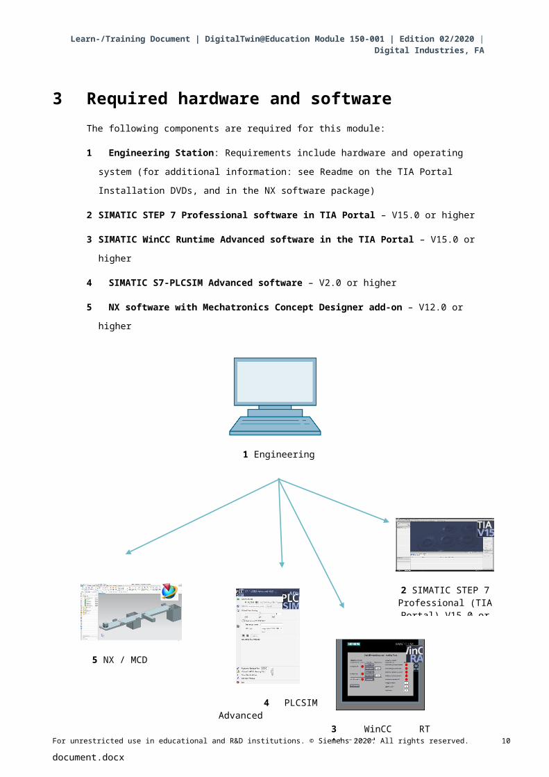
3 Required hardware and softwareThe following components are required for this module:
1 Engineering Station: Requirements include hardware and operating system (for additional
information: see Readme on the TIA Portal Installation DVDs, and in the NX software
package)
2 SIMATIC STEP 7 Professional software in TIA Portal – V15.0 or higher
3 SIMATIC WinCC Runtime Advanced software in the TIA Portal – V15.0 or higher
4 SIMATIC S7-PLCSIM Advanced software – V2.0 or higher
5 NX software with Mechatronics Concept Designer add-on – V12.0 or higher
Figure 1: Overview of required software and hardware components in this module
As you can see from Figure 1, the engineering station is the only hardware component of the
system. The remaining components are based exclusively on software.
For unrestricted use in educational and R&D institutions. © Siemens 2020. All rights reserved. 8
document.docx
5 NX / MCD
4 PLCSIM Advanced
3 WinCC RT Advanced
2 SIMATIC STEP 7 Professional (TIA
Portal) V15.0 or higher
1 Engineering station
Learn-/Training Document | DigitalTwin@Education Module 150-001 | Edition 02/2020 | Digital Industries, FA
4 Theory
4.1 Virtual commissioning
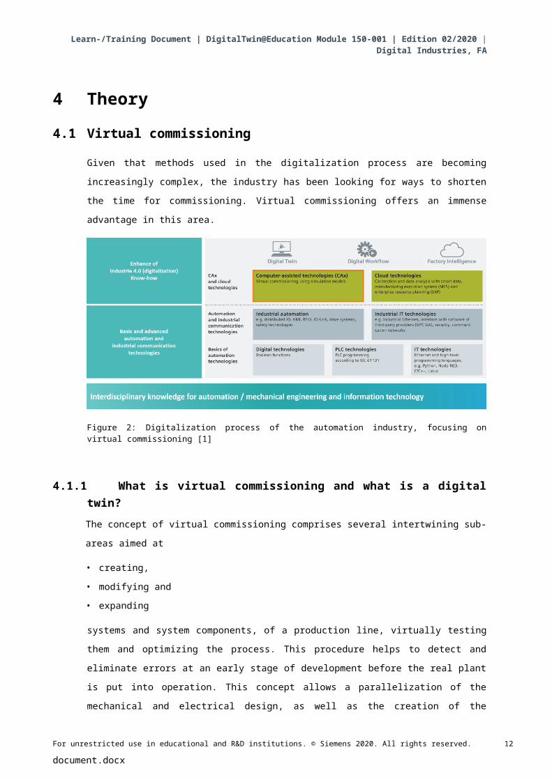
Given that methods used in the digitalization process are becoming increasingly complex, the
industry has been looking for ways to shorten the time for commissioning. Virtual commissioning
offers an immense advantage in this area.
Figure 2: Digitalization process of the automation industry, focusing on virtual commissioning [1]
4.1.1 What is virtual commissioning and what is a digital twin?The concept of virtual commissioning comprises several intertwining sub-areas aimed at
• creating,
• modifying and
• expanding
systems and system components, of a production line, virtually testing them and optimizing the
process. This procedure helps to detect and eliminate errors at an early stage of development
before the real plant is put into operation. This concept allows a parallelization of the mechanical
and electrical design, as well as the creation of the control software. This speed up the
commissioning of the real plant and also lowers possible costs of errors after delivery, as these
errors have ideally already been corrected during development.
For unrestricted use in educational and R&D institutions. © Siemens 2020. All rights reserved. 9
document.docx
Learn-/Training Document | DigitalTwin@Education Module 150-001 | Edition 02/2020 | Digital Industries, FA
Virtual commissioning is based on a 3D simulation model that simulates the behavior of a plant,
production line or individual cell. This map is also known as a "digital twin". The extent to which
the virtual model resembles the real model depends on the model's level of detail: The more
features that can be assigned to the simulation model, the more accurate the map of the real
plant. However, each additional feature also means more development effort for the model. A
compromise needs to be found between the necessary simulation depth and the development
effort for the current project.
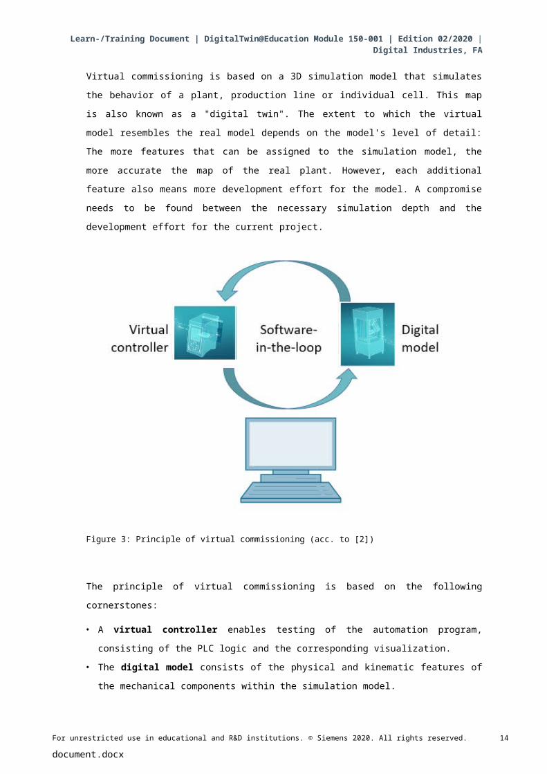
Figure 3: Principle of virtual commissioning (acc. to [2])
The principle of virtual commissioning is based on the following cornerstones:
• A virtual controller enables testing of the automation program, consisting of the PLC logic
and the corresponding visualization.
• The digital model consists of the physical and kinematic features of the mechanical
components within the simulation model.
• The behavior and functionality can be validated through the interaction between the virtual controller and the digital model.
This concept, as shown in Figure 3, corresponds to the Software-in-the-Loop (SiL) modeling
method: All components are detached from real hardware, the simulations are run exclusively on
development computers.
For unrestricted use in educational and R&D institutions. © Siemens 2020. All rights reserved. 10
document.docx
Learn-/Training Document | DigitalTwin@Education Module 150-001 | Edition 02/2020 | Digital Industries, FA
If you were to perform commissioning with real hardware, using a real PLC for example, one
would speak of the Hardware-in-the-loop (HiL) concept.
However, the Software-in-the-loop simulation principle will be used as a basis for this workshop.
There are several ways to create a digital model. Using the NX tool you can create a 3D model of
the mechanical components and create a map of the real plant. Using the NX add-on
Mechatronics Concept Designer, this map can be turned into a complete digital twin by adding
physical and kinematic features. In addition to NX and MCD, the TECHNOMATIX Process
Simulate software of Siemens can also be used to create a digital model. However, it also maps
other features.
The SIMATIC S7-PLCSIM Advanced software can be used to simulate a PLC. The configuration
is carried out completely in the TIA Portal and downloaded to the simulated device via a virtual
interface. For additional information on this, refer to Chapter 4.1.2.
The CAD/CAE/CAM terminology is explained in Chapter 4.1.3. For a description of NX, refer to
Chapter 4.1.4. The NX add-on Mechatronics Concept Designer (MCD) is presented in
Chapter 4.1.5. In Chapter 4.1.6 a short comparison is made with the TECHNOMATIX Process
Simulate simulation software.
4.1.2 SIMATIC S7-PLCSIM Advanced:The SIMATIC S7-PLCSIM Advanced tool is used to create and commission a virtual controller.
This is limited to the two most common Siemens controllers: S7-1500 and ET 200SP. Through
use of the virtual controller, the use of a real PLC is not necessary, so that commissioning can be
carried out completely by the software. In addition to the loaded PLC program, other controller
functions are also available for the simulation, such as the web server, the OPC UA server and
other S7 communications. This means that early testing of the controller software is already
possible without hardware. This saves rework time for the customer.
4.1.3 What is CAD/CAE/CAM?In the course of the digital representation of products, the following terminology has been
established in the design phase.
Computer-aided design (CAD) describes the use of computers to create, modify, optimize and
analyze any design. These designs can be created in two- or three-dimensional space. CAD is
often used in connection with mechanical designs in mechanical engineering, but is now also
used in many sectors, such as architecture, multimedia or automation engineering.
Computer-aided engineering (CAE) uses a CAD design and enhances this with dynamic features
for simulations. Depending on the application, these are physical features, kinematics and
kinetics as well as flow or thermal analyses.
Computer-aided manufacturing (CAM) uses a CAD design to generate a manufacturing plan for
(C)NC machines.
For unrestricted use in educational and R&D institutions. © Siemens 2020. All rights reserved. 11
document.docx
Learn-/Training Document | DigitalTwin@Education Module 150-001 | Edition 02/2020 | Digital Industries, FA
4.1.4 NXNX is a Siemens PLM software tool, which enables the design of virtual 2D and 3D models. It
consists of various individual modules that cover wide areas of the product design phase for
various CAD, CAE and CAM applications. This includes product design, product modeling,
product validation and product documentation. This simplifies the interaction of a company's
various design departments, such as between mechanical design, onboard electronics and
automation engineering.
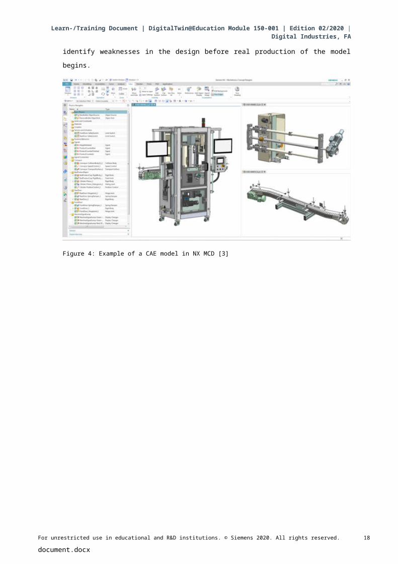
4.1.5 Mechatronics Concept DesignerThe Mechatronics Concept Designer is an expansion module for the NX software and includes a
"physics engine" to assign physical and kinematic features to the CAD model. Furthermore, the
model can be equipped with sensors and actuators and the corresponding signals for controlling
these can be assigned. Using sequence information of the operation or motion sequences, the
automation engineer can validate the interaction of mechanics, electronics and automation. All
previous properties can be tested directly using an integrated simulation to identify weaknesses
in the design before real production of the model begins.
Figure 4: Example of a CAE model in NX MCD [3]
For unrestricted use in educational and R&D institutions. © Siemens 2020. All rights reserved. 12
document.docx
Learn-/Training Document | DigitalTwin@Education Module 150-001 | Edition 02/2020 | Digital Industries, FA
4.1.6 Alternative to MCD: TECNOMATIX Process SimulateThe TECNOMATIX Process Simulate software provides another option for creating a simulation
model. The main difference from the Mechatronics Concept Designer (see Chapter 4.1.5) is that
the tool is not based on a "physics engine". Therefore, the components do not receive any
physical or kinematic features. A major advantage is that the interactions of several processes as
well as the intertwining of the processes of several cells can be reproduced and an entire
production line can be simulated more easily. In addition, TECNOMATIX Process Simulate is
often used for programming a robot program. For this purpose, Tecnomatix provides simulated
robot controllers on which the original robot program can be executed. Finally, it is possible to
create logics in Tecnomatix, so that the behavior of components can be demonstrated.
The behavior model of this workshop is instead based on physical features, which is why
TECNOMATIX Process Simulate is not used here.
4.2 Model description of the digital twin "SortingPlant"
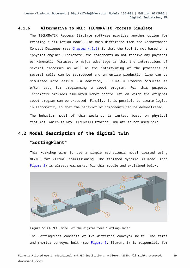
This workshop aims to use a simple mechatronic model created using NX/MCD for virtual
commissioning. The finished dynamic 3D model (see Figure 5) is already earmarked for this
module and explained below.
Figure 5: CAD/CAE model of the digital twin "SortingPlant"
The SortingPlant consists of two different conveyor belts. The first and shorter conveyor belt (see
Figure 5, Element 1) is responsible for transporting the workpieces to the sorting process. Both
cuboid and cylindrical workpieces are possible as workpieces (see Figure 5, Element 6). It should
be noted that the cuboid workpiece is higher than the cylindrical workpiece. The first light sensor
(see Figure 5, Element 7) is used to count the workpieces that pass through the sorting process.
The second and longer conveyor belt (see Figure 5, Element 2) is responsible for sorting the
workpieces. The pusher (see Figure 5, Element 3) is used to separate out the cylindrical
workpieces into the first container (see Figure 5, Element 4). The total number of cylindrical
workpieces in the sorting process is accordingly incremented by one. A combination of two light
sensors (see Figure 5, Element 8) is used to unambiguously identify the cylindrical workpiece.
Due to the lower height, only the lower of the two light sensors is triggered for the cylindrical
For unrestricted use in educational and R&D institutions. © Siemens 2020. All rights reserved. 13
document.docx
Learn-/Training Document | DigitalTwin@Education Module 150-001 | Edition 02/2020 | Digital Industries, FA
workpiece, while both light sensors are activated for the cuboid workpiece. An XOR combination
of both light sensors provides a suitable logic for identifying the cylindrical workpieces.
If it is a cuboid workpiece, it is transported via the conveyor belt to the second container. (see
Figure 5, Element 5). The last light sensor (see Figure 5, Element 9) counts the total number of
cuboid workpieces in the sorting process.
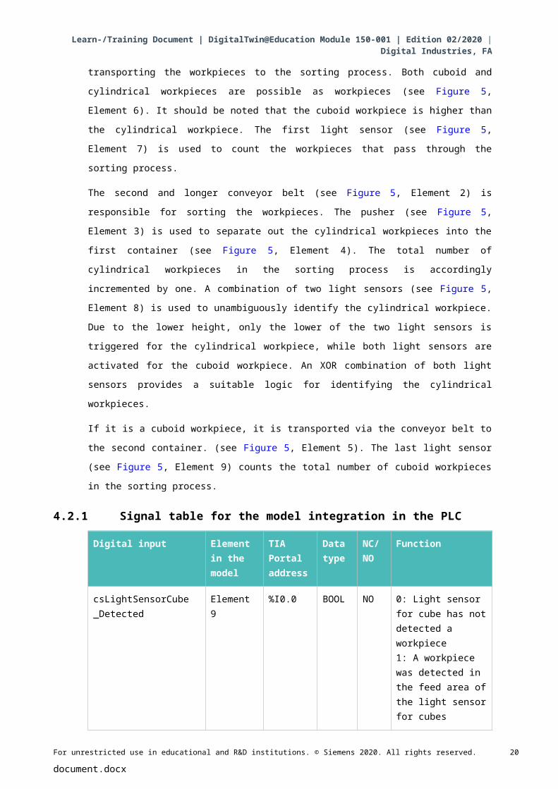
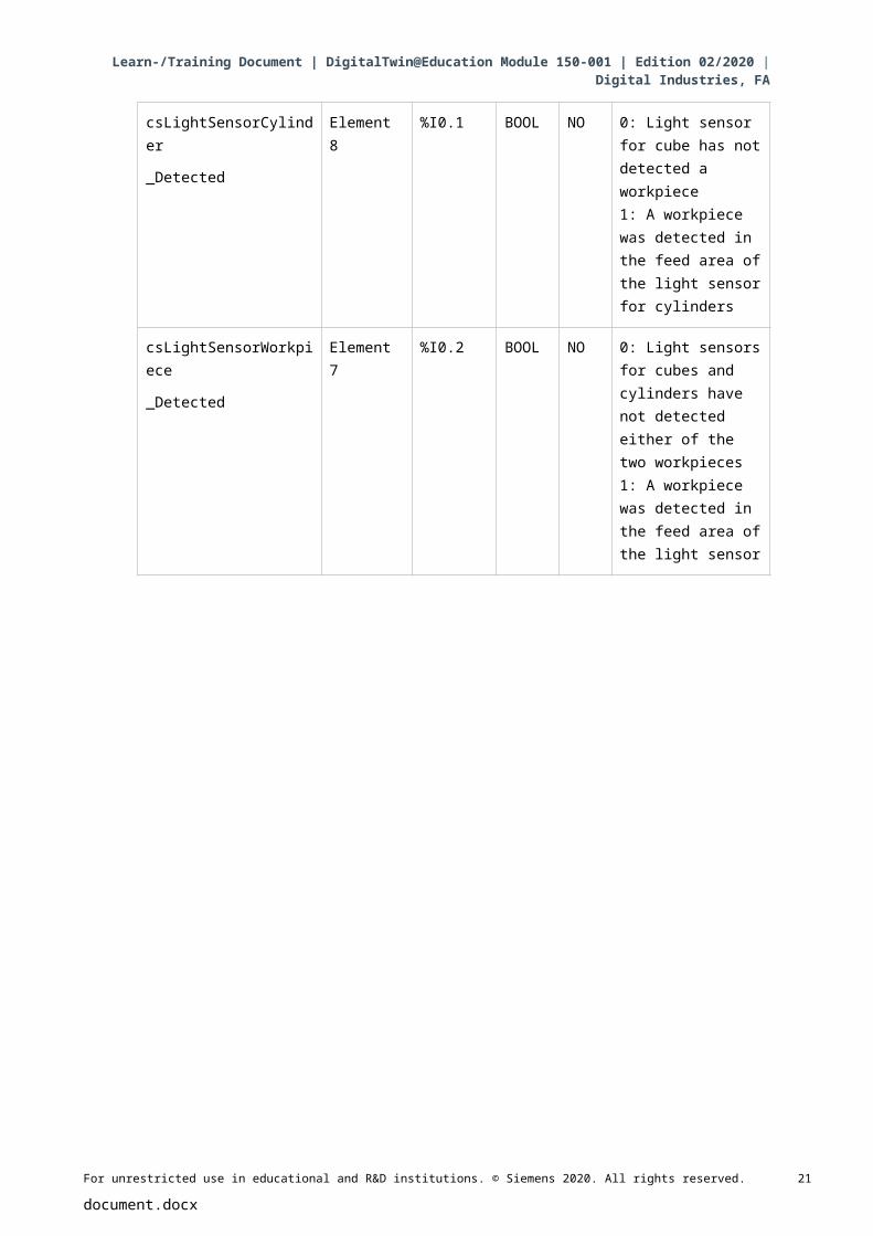
4.2.1 Signal table for the model integration in the PLC
Digital input Element in the model
TIA Portal address
Data type
NC/ NO
Function
csLightSensorCube_Detected
Element 9 %I0.0 BOOL NO 0: Light sensor for cube has not detected a workpiece1: A workpiece was detected in the feed area of the light sensor for cubes
csLightSensorCylinder
_Detected
Element 8 %I0.1 BOOL NO 0: Light sensor for cube has not detected a workpiece1: A workpiece was detected in the feed area of the light sensor for cylinders
csLightSensorWorkpiece
_Detected
Element 7 %I0.2 BOOL NO 0: Light sensors for cubes and cylinders have not detected either of the two workpieces1: A workpiece was detected in the feed area of the light sensor
For unrestricted use in educational and R&D institutions. © Siemens 2020. All rights reserved. 14
document.docx
Learn-/Training Document | DigitalTwin@Education Module 150-001 | Edition 02/2020 | Digital Industries, FA
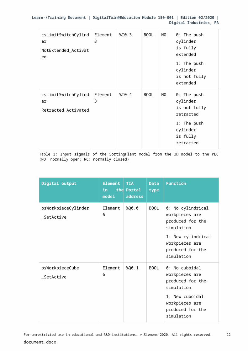
csLimitSwitchCylinder
NotExtended_Activated
Element 3 %I0.3 BOOL NO 0: The push cylinder is fully extended
1: The push cylinder is not fully extended
csLimitSwitchCylinder
Retracted_Activated
Element 3 %I0.4 BOOL NO 0: The push cylinder is not fully retracted
1: The push cylinder is fully retracted
Table 1: Input signals of the SortingPlant model from the 3D model to the PLC (NO: normally open; NC: normally closed)
Digital output Element in the model
TIA Portal address
Data type
Function
osWorkpieceCylinder
_SetActive
Element 6 %Q0.0 BOOL 0: No cylindrical workpieces are produced for the simulation
1: New cylindrical workpieces are produced for the simulation
osWorkpieceCube
_SetActive
Element 6 %Q0.1 BOOL 0: No cuboidal workpieces are produced for the simulation
1: New cuboidal workpieces are produced for the simulation
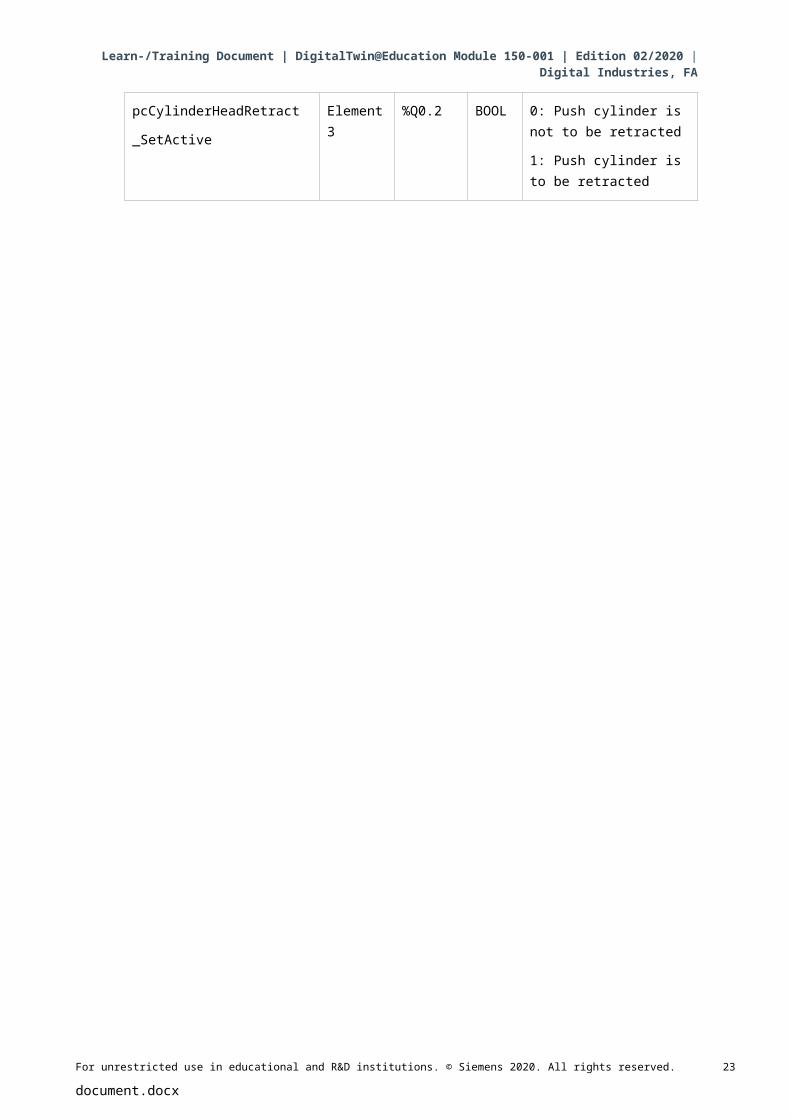
pcCylinderHeadRetract
_SetActive
Element 3 %Q0.2 BOOL 0: Push cylinder is not to be retracted
1: Push cylinder is to be retracted
For unrestricted use in educational and R&D institutions. © Siemens 2020. All rights reserved. 15
document.docx
Learn-/Training Document | DigitalTwin@Education Module 150-001 | Edition 02/2020 | Digital Industries, FA
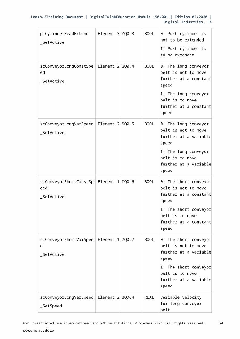
pcCylinderHeadExtend
_SetActive
Element 3 %Q0.3 BOOL 0: Push cylinder is not to be extended
1: Push cylinder is to be extended
scConveyorLongConstSpeed
_SetActive
Element 2 %Q0.4 BOOL 0: The long conveyor belt is not to move further at a constant speed
1: The long conveyor belt is to move further at a constant speed
scConveyorLongVarSpeed
_SetActive
Element 2 %Q0.5 BOOL 0: The long conveyor belt is not to move further at a variable speed
1: The long conveyor belt is to move further at a variable speed
scConveyorShortConstSpeed
_SetActive
Element 1 %Q0.6 BOOL 0: The short conveyor belt is not to move further at a constant speed
1: The short conveyor belt is to move further at a constant speed
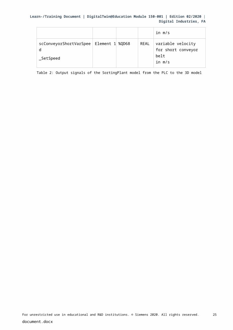
scConveyorShortVarSpeed
_SetActive
Element 1 %Q0.7 BOOL 0: The short conveyor belt is not to move further at a variable speed
1: The short conveyor belt is to move further at a variable speed
scConveyorLongVarSpeed
_SetSpeed
Element 2 %QD64 REAL variable velocity for long conveyor belt in m/s
scConveyorShortVarSpeed
_SetSpeed
Element 1 %QD68 REAL variable velocityfor short conveyor beltin m/s
Table 2: Output signals of the SortingPlant model from the PLC to the 3D model
For unrestricted use in educational and R&D institutions. © Siemens 2020. All rights reserved. 16
document.docx
Learn-/Training Document | DigitalTwin@Education Module 150-001 | Edition 02/2020 | Digital Industries, FA
5 TaskIn this module, a preconfigured digital twin is to be commissioned. To do this, you must first
unpack the provided projects and load them. In addition to the program for the CPU and the HMI,
this also includes the mechatronic model from the Mechatronics Concept Designer (MCD). The
interface between virtual PLC, simulated HMI and the digital twin is implemented using PLCSIM
Advanced.
6 PlanningAlready finished projects and files are available for this module, so that commissioning with
subsequent testing can be carried out exclusively here.
The PLC and the HMI were created and configured with the SIMATIC STEP 7 Professional V15.0 software. The PLC is simulated virtually using the SIMATIC S7-PLCSIM Advanced V2.0 software. The HMI is simulated with the TIA Portal option package SIMATIC WinCC Runtime Advanced V15.0. The virtual PLC and the simulated HMI are connected via the simulated
Ethernet interfaces.
The digital twin was created using Mechatronics Concept Designer V12.0. The suitably
configured signals are already connected to the inputs and outputs of the PLC.
For unrestricted use in educational and R&D institutions. © Siemens 2020. All rights reserved. 17
document.docx
Learn-/Training Document | DigitalTwin@Education Module 150-001 | Edition 02/2020 | Digital Industries, FA
7 Structured step-by-step instructionsThe following describes how to perform virtual commissioning of the dynamic 3D model. The
instructions cover the following:
• Commissioning of the virtual PLC and the HMI simulation using a prepared TIA project
• Setting up a virtual PLC in PLCSIM Advanced
• Downloading the programs to the virtual PLC and the simulated HMI
• Loading the dynamic 3D model and starting the simulation in NX MCD
• Testing the functionality of the digital twin using two example scenarios
You can find more information about this module at some places in this document. This
information is provided in a blue-green information box and serves to deepen your knowledge.
7.1 Retrieving an existing project in the TIA Portal
Start the "TIA Portal V15.0" software. You can do this either by searching for TIA Portal V15
in the Start menu or by double-clicking the corresponding icon on the desktop.
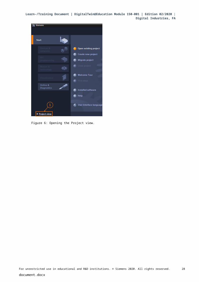
After that, the TIA Portal should open at the start screen. If not set by default, open the
"Project View" of the TIA Portal, as shown in Figure 6, Step 1. ( Project view)
Figure 6: Opening the Project view.
For unrestricted use in educational and R&D institutions. © Siemens 2020. All rights reserved. 18
document.docx
Learn-/Training Document | DigitalTwin@Education Module 150-001 | Edition 02/2020 | Digital Industries, FA
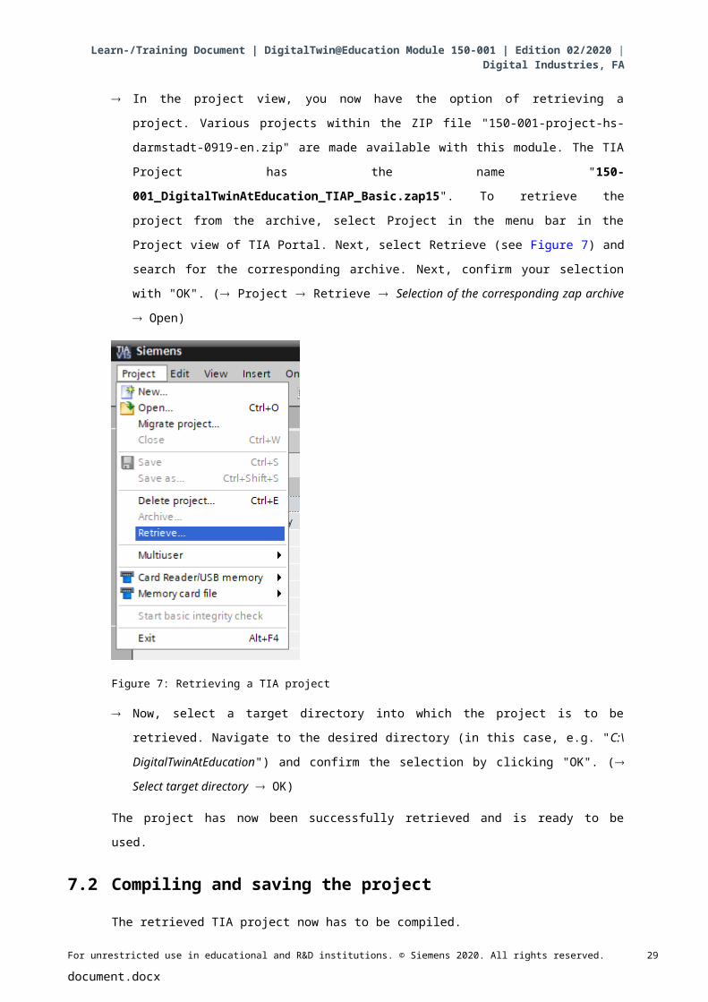
In the project view, you now have the option of retrieving a project. Various projects within the
ZIP file "150-001-project-hs-darmstadt-0919-en.zip" are made available with this module. The
TIA Project has the name "150-001_DigitalTwinAtEducation_TIAP_Basic.zap15". To
retrieve the project from the archive, select Project in the menu bar in the Project view of TIA
Portal. Next, select Retrieve (see Figure 7) and search for the corresponding archive. Next,
confirm your selection with "OK". ( Project Retrieve Selection of the corresponding zap
archive Open)
Figure 7: Retrieving a TIA project
Now, select a target directory into which the project is to be retrieved. Navigate to the desired
directory (in this case, e.g. "C:\DigitalTwinAtEducation") and confirm the selection by clicking
"OK". ( Select target directory OK)
The project has now been successfully retrieved and is ready to be used.
7.2 Compiling and saving the project
The retrieved TIA project now has to be compiled.
However, you should first check the Ethernet communication. In the provided TIA project, the IP
address 192.168.0.1 was selected for the CPU and the IP address 192.168.0.10 for the HMI. If
these addresses are already assigned in your system, you must adapt them according to existing
SCE curriculums / training curriculums, as listed in Chapter 2 .
For unrestricted use in educational and R&D institutions. © Siemens 2020. All rights reserved. 19
document.docx
Learn-/Training Document | DigitalTwin@Education Module 150-001 | Edition 02/2020 | Digital Industries, FA
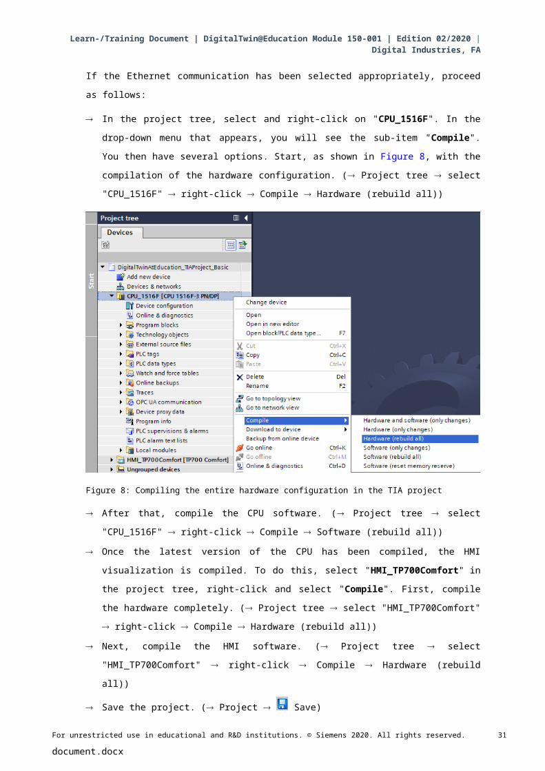
If the Ethernet communication has been selected appropriately, proceed as follows:
In the project tree, select and right-click on "CPU_1516F". In the drop-down menu that
appears, you will see the sub-item "Compile". You then have several options. Start, as
shown in Figure 8, with the compilation of the hardware configuration. ( Project tree
select "CPU_1516F" right-click Compile Hardware (rebuild all))
Figure 8: Compiling the entire hardware configuration in the TIA project
After that, compile the CPU software. ( Project tree select "CPU_1516F" right-click
Compile Software (rebuild all))
Once the latest version of the CPU has been compiled, the HMI visualization is compiled. To
do this, select "HMI_TP700Comfort" in the project tree, right-click and select "Compile".
First, compile the hardware completely. ( Project tree select "HMI_TP700Comfort"
right-click Compile Hardware (rebuild all))
Next, compile the HMI software. ( Project tree select "HMI_TP700Comfort" right-click
Compile Hardware (rebuild all))
Save the project. ( Project Save)
The TIA project is then functional and can be used for a simulation. For the following steps, keep the TIA Portal open:
For unrestricted use in educational and R&D institutions. © Siemens 2020. All rights reserved. 20
document.docx
Learn-/Training Document | DigitalTwin@Education Module 150-001 | Edition 02/2020 | Digital Industries, FA
7.3 Start a virtual CPU via PLCSIM Advanced
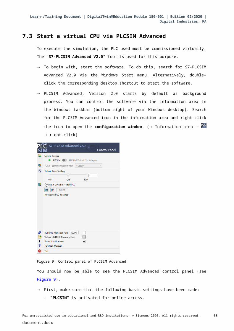
To execute the simulation, the PLC used must be commissioned virtually. The "S7-PLCSIM Advanced V2.0" tool is used for this purpose.
To begin with, start the software. To do this, search for S7-PLCSIM Advanced V2.0 via the
Windows Start menu. Alternatively, double-click the corresponding desktop shortcut to start
the software.
PLCSIM Advanced, Version 2.0 starts by default as background process. You can control the
software via the information area in the Windows taskbar (bottom right of your Windows
desktop). Search for the PLCSIM Advanced icon in the information area and right-click the
icon to open the configuration window. ( Information area right-click)
Figure 9: Control panel of PLCSIM Advanced
You should now be able to see the PLCSIM Advanced control panel (see Figure 9).
First, make sure that the following basic settings have been made:
– "PLCSIM" is activated for online access.
Virtual Time Scaling is switched off, i.e. it remains at multiplier 1.
For unrestricted use in educational and R&D institutions. © Siemens 2020. All rights reserved. 21
document.docx
Learn-/Training Document | DigitalTwin@Education Module 150-001 | Edition 02/2020 | Digital Industries, FA
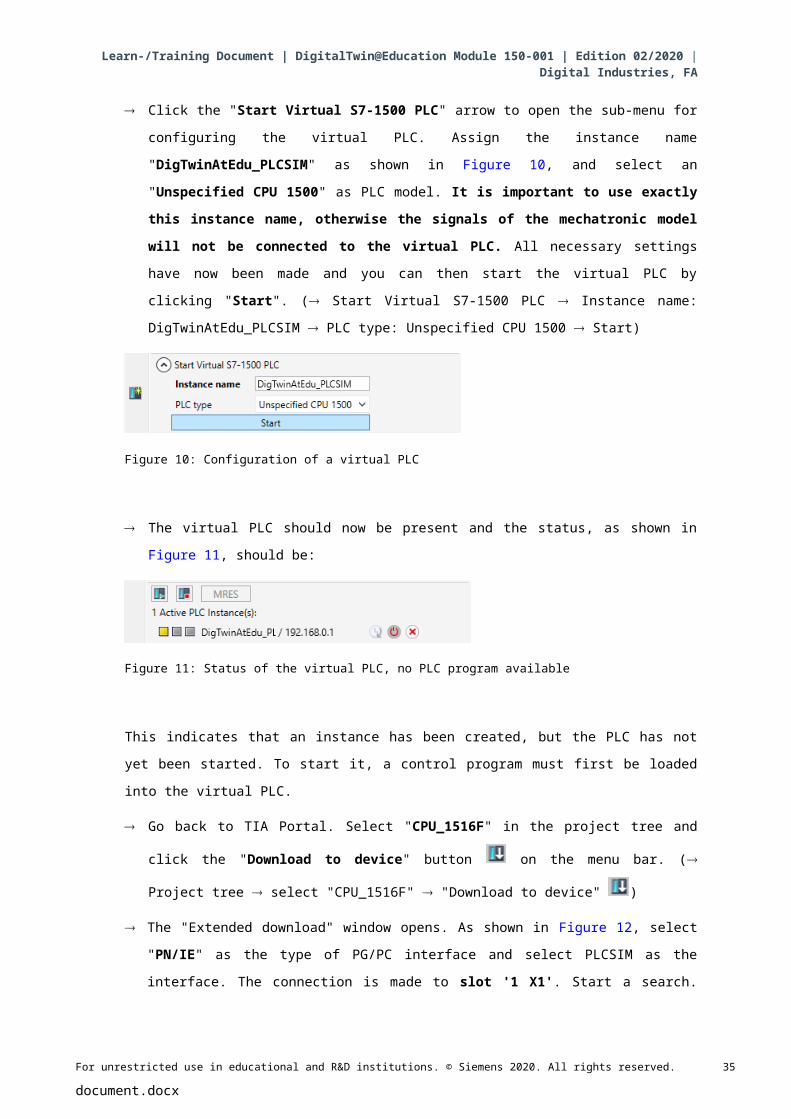
Click the "Start Virtual S7-1500 PLC" arrow to open the sub-menu for configuring the virtual
PLC. Assign the instance name "DigTwinAtEdu_PLCSIM" as shown in Figure 10, and select
an "Unspecified CPU 1500" as PLC model. It is important to use exactly this instance name, otherwise the signals of the mechatronic model will not be connected to the virtual PLC. All necessary settings have now been made and you can then start the virtual
PLC by clicking "Start". ( Start Virtual S7-1500 PLC Instance name:
DigTwinAtEdu_PLCSIM PLC type: Unspecified CPU 1500 Start)
Figure 10: Configuration of a virtual PLC
The virtual PLC should now be present and the status, as shown in Figure 11, should be:
Figure 11: Status of the virtual PLC, no PLC program available
This indicates that an instance has been created, but the PLC has not yet been started. To start
it, a control program must first be loaded into the virtual PLC.
Go back to TIA Portal. Select "CPU_1516F" in the project tree and click the "Download to
device" button on the menu bar. ( Project tree select "CPU_1516F" "Download to
device" )
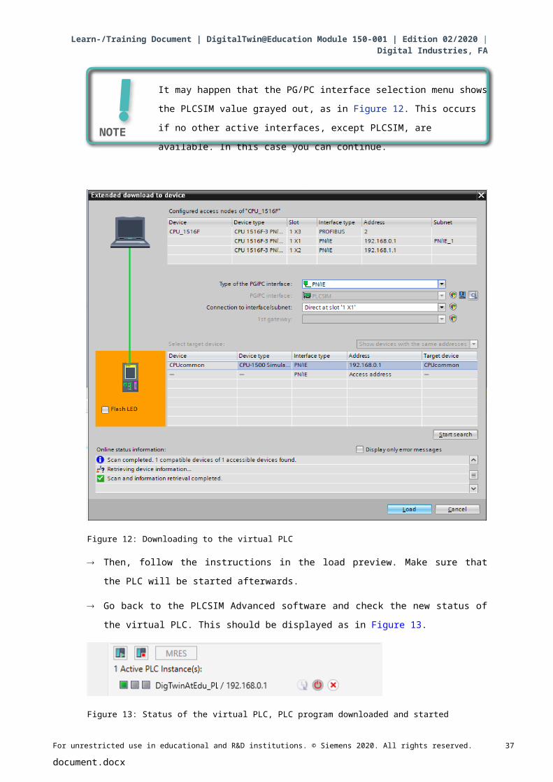
The "Extended download" window opens. As shown in Figure 12, select "PN/IE" as the type
of PG/PC interface and select PLCSIM as the interface. The connection is made to slot '1 X1'. Start a search. The virtual PLC from the PLCSIM Advanced instance should be found.
Complete the process by clicking "Load".
( Type of the PG/PC interface: PN/IE PG/PC interface: PLCSIM Connection to
interface: Slot '1 X1' Click "Start search" button Select virtual PLC as target device
Click "Load")
For unrestricted use in educational and R&D institutions. © Siemens 2020. All rights reserved. 22
document.docx
Learn-/Training Document | DigitalTwin@Education Module 150-001 | Edition 02/2020 | Digital Industries, FA
It may happen that the PG/PC interface selection menu shows the PLCSIM
value grayed out, as in Figure 12. This occurs if no other active interfaces,
except PLCSIM, are available. In this case you can continue.
Figure 12: Downloading to the virtual PLC
Then, follow the instructions in the load preview. Make sure that the PLC will be started
afterwards.
Go back to the PLCSIM Advanced software and check the new status of the virtual PLC. This
should be displayed as in Figure 13.
Figure 13: Status of the virtual PLC, PLC program downloaded and started
For unrestricted use in educational and R&D institutions. © Siemens 2020. All rights reserved. 23
document.docx
NOTE
Learn-/Training Document | DigitalTwin@Education Module 150-001 | Edition 02/2020 | Digital Industries, FA
Now, you can see that the virtual PLC in PLCSIM Advanced has been successfully
commissioned.
7.4 Start a simulated HMI
After successfully starting a virtual PLC with PLCSIM Advanced, an HMI is simulated in this step.
To do this, return to the TIA Project already opened in Step 7.1.
Select "HMI_TP700Comfort" in the project tree. Right-click the associated configuration to
open it and navigate in the opened shortcut menu to item "Start simulation". (see Figure
14). Alternatively, you can also start the simulation with Ctrcl+Shift+X.
Figure 14: Starting the HMI simulation
For unrestricted use in educational and R&D institutions. © Siemens 2020. All rights reserved. 24
document.docx
Learn-/Training Document | DigitalTwin@Education Module 150-001 | Edition 02/2020 | Digital Industries, FA
The HMI simulation tool "WinCC Runtime Advanced" now starts and displays the preconfigured
HMI in a separate window.
Figure 15: HMI simulation of the model control in WinCC Runtime Advanced
Next, you should first check whether the input/output fields have a start value, as in this case
"0" (see for comparison Figure 15). If the fields are not initialized, which is shown by the
expression "#####", the configured connection is faulty. Therefore, you should check the
hardware configuration and connection of the CPU1516F and HMI_TP700 again. If in doubt,
refer to the documents listed in Chapter 2 again.
The HMI is now ready for virtual commissioning.
For unrestricted use in educational and R&D institutions. © Siemens 2020. All rights reserved. 25
document.docx
Learn-/Training Document | DigitalTwin@Education Module 150-001 | Edition 02/2020 | Digital Industries, FA
7.5 Open the prepared digital twin and start simulation in NX MCD
For the last part of the virtual commissioning, the physical simulation model from the CAE
program NX MCD is now required, whose simulation is prepared and started in the following
steps.
The ZIP file "150-001-project-hs-darmstadt-0919-en.zip" also contains the archive with the
necessary MCD files. Using Windows or a separate tool, unpack the archive "150-001_DigitalTwinAtEducation_MCD_dynModel_Signals.zip" into a folder of your choice. (here e.g. "C:\DigitalTwinAtEducation")
Start the "Mechatronics Concept Designer 12.0" software. To do this, you can search for
Mechatronics Concept Designer 12.0 in the start menu or open the corresponding shortcut
on the desktop by double-clicking on it.
You should see the main menu of the Mechatronics Concept Designer. Open the MCD
project "SortingPlant". Click on the "Open" icon in the menu bar of the Mechatronics
Concept Designer. The selection window from Figure 16 appears, in which you can navigate
to the path of the unpacked archive. Select the "SortingPlant" file from the displayed Part files
(*.prt). To load only the relevant data of the digital twin, make sure in the options that the file
is only "partially loaded". Finish the process by clicking "OK". ( Open select path to
unpacked archive select SortingPlant.prt Option: Partially Load "OK")
Figure 16: Opening the digital twin "SortingPlant"
For unrestricted use in educational and R&D institutions. © Siemens 2020. All rights reserved. 26
document.docx
Learn-/Training Document | DigitalTwin@Education Module 150-001 | Edition 02/2020 | Digital Industries, FA
The project opens and the 3D model of the sorting plant is displayed in the lower right
window. (see Figure 17).
Figure 17: Model representation of the digital twin in MCD
To start the simulation, go to the "Home page" menu in the menu bar at the top (see Figure
17, Step 1). There you can now find, among other things, the icons to control the NX MCD
simulation (see Figure 17, Step 2). Click the Start icon to start the simulation. You can see
from the lower display bar of the program (see Figure 18) that the simulation is running.
(Start page Simulate Start )
Figure 18: Simulation environment and simulation details in MCD
For unrestricted use in educational and R&D institutions. © Siemens 2020. All rights reserved. 27
document.docx
Learn-/Training Document | DigitalTwin@Education Module 150-001 | Edition 02/2020 | Digital Industries, FA
The simulation of all required individual components is now in operation and you can test the
interaction between them below.
7.6 Testing of interactions between CPU, HMI and digital twin
To test the function of the three simulations, first refer to the following two examples. To illustrate
the necessary steps in the HMI simulation and to classify the HMI signals for the models in MCD,
you can refer to Figure 20 for scenario 1 and Figure 21 for scenario 2. To appraise the reaction
of the simulations, it is helpful to keep the simulated HMI in WinCC Runtime Advanced as well as
the virtual 3D model in NX MCD visible in parallel on the screen.
For unrestricted use in educational and R&D institutions. © Siemens 2020. All rights reserved. 28
document.docx
NOTE
If the 3D view of the SortingPlant differs from the view shown in Figure 17
and Figure 18, you are not in the standard view of MCD, the so-called
"Trimetric view". To return to this view, either select Trimetric in Orient
view in the View bar or press the Pos1 key of a traditional computer
keyboard. Alternatively, you can search for Trimetric using NX's search
function at the top right of the screen (see Figure 19) and select Trimetric
from the drop-down list.
Learn-/Training Document | DigitalTwin@Education Module 150-001 | Edition 02/2020 | Digital Industries, FA
Figure 19: Go to "Trimetric view" in MCD
For unrestricted use in educational and R&D institutions. © Siemens 2020. All rights reserved. 29
document.docx
Learn-/Training Document | DigitalTwin@Education Module 150-001 | Edition 02/2020 | Digital Industries, FA
7.6.1 Scenario 1: Movement of the sorting system at constant speed
Figure 20: Sequence of Scenario 1 in HMI simulation and display of HMI signals in MCD model (orange: steps for scenario 1; blue: input signals; green: output signals)
For unrestricted use in educational and R&D institutions. © Siemens 2020. All rights reserved. 30
document.docx
Learn-/Training Document | DigitalTwin@Education Module 150-001 | Edition 02/2020 | Digital Industries, FA
First, reset the simulation. To do this, press the "Reset Simulation" button in the simulated
HMI (see Figure 20, Step 1). All buttons should be switched off and all I/O fields should be
reset. No changes are visible in the 3D simulation in NX MCD, the cuboid body retains its
position and the push cylinder is retracted.
Next, press the "Constant Speed" button of the "ConveyorShort" conveyor belt in the HMI
(see Figure 20, Step 2). You should now see that the cuboid workpiece is moving along the
first conveyor belt. When the workpiece has reached the end of the conveyor belt, the
"LightSensorWorkpieceDetected" light sensor (see Figure 20, Step 3) is triggered, which
increments the "Workpiece Counter" (see Figure 20, Step 4). However, the workpiece now
stops and is not transported via the second conveyor belt, as the second conveyor belt has not
yet been activated in the PLC program or via the HMI.
To do this, start the second conveyor belt "ConveyorLong" at constant speed by clicking its
"Constant Speed" button (see Figure 20, Step 5). Now the cuboid workpiece should continue
to move. During this process you can see that the "LightSensorCylinderDetected" signal
does not trigger, because both middle light sensors react to the workpiece. As described in
Chapter 4.2, in this case it is definitely not a cylindrical workpiece. The light sensor
"LightSensorCubeDetected" (see Figure 20, Step 6) is activated for this. As a result, the
"CubeCounter" is incremented (see Figure 20, Step 7). The cuboid workpiece then falls into
the rear container.
Because there are now no more workpieces left, press the "WorkpieceSources" button (see
Figure 20, Step 8) to generate additional workpieces virtually. Cuboid and cylindrical
workpieces subsequently appear at regular intervals due to the MCD simulation. While the
above-described workflow for the cuboid pieces does not change, the following behavior
occurs for the cylindrical workpieces: As with the cuboid workpieces, the
"LightSensorWorkpieceDetected" light sensor is triggered, which increments the "Workpiece Counter". Because the cylindrical workpiece is smaller in height than the cuboid workpiece,
only one of the two light sensor in the middle is triggered. Therefore, this object is identified as
a cylindrical workpiece, which is why the signal "LightSensorCylinderDetected" is triggered
(see Figure 20, Step 9), so that the "CylinderCounter" is incremented (see Figure 20, Step
10). The cylindrical workpiece is now sorted into the front container using the push cylinder
(see Figure 20, Step 11).
For unrestricted use in educational and R&D institutions. © Siemens 2020. All rights reserved. 31
document.docx
Learn-/Training Document | DigitalTwin@Education Module 150-001 | Edition 02/2020 | Digital Industries, FA
7.6.2 Scenario 2: Movement of the sorting system at variable speed
Figure 21: Sequence of Scenario 2 in HMI simulation and display of HMI signals in MCD model (orange: steps for scenario 2; blue: input signals; green: output signals)
For unrestricted use in educational and R&D institutions. © Siemens 2020. All rights reserved. 32
document.docx
Learn-/Training Document | DigitalTwin@Education Module 150-001 | Edition 02/2020 | Digital Industries, FA
Deactivate all buttons of the HMI for this next scenario, stop the simulation in NX MCD by
clicking the stop symbol and then reset the simulation by clicking "ResetSimulation" in
the HMI (see Figure 21, Step 1). Then restart the simulation in NX MCD by clicking the Start
button . All buttons in the HMI should now be deactivated and all I/O fields reset. The
cuboid body in NX MCD retains its position and the push cylinder is retracted.
Select the "Variable Speed" button on the "ConveyorShort" conveyor belt (see Figure 21,
Step 2). The conveyor remains stopped. The reason for this is that the input field for the
speed is still set to 0% and the motor is therefore not running yet. Set the speed to 50% (see
Figure 21, Step 3). Now the cuboid piece should move along the first conveyor belt. At the
end of the conveyor belt, the "WorkpieceCounter" is incremented again (see Figure 21,
Step 5) via a positive edge at "LightSensorWorkpieceDetected" (see Figure 21, Step 4).
Since the second conveyor belt has not yet been activated, the cuboid piece remains at the
end of the conveyor belt.
First enter a motor speed of 50% for the second conveyor belt "ConveyorLong" in the input
field (see Figure 21, Step 6). Next, activate the "Variable Speed" button on the
"ConveyorLong" conveyor belt (see Figure 21, Step 7). The cuboid workpiece will then
move further. In this case too, the "LightSensorCylinderDetected" signal is not triggered
because both middle light sensors trigger. However, the "LightSensorCubeDetected" signal
(see Figure 21, Step 8) is set, which increments the "CubeCounter" (see Figure 21, Step 9).
The workpiece falls into the rear container.
However, there are no further workpieces, as the generation of new workpieces has not yet
been activated. To do this, click the "WorkpieceSources" button (see Figure 21, Step 10).
Rectangular and cylindrical workpieces should now be generated at regular intervals. As
already noted in Scenario 1 (Chapter 7.6.1), the cylindrical workpiece is clearly identified on
the basis of the height in the middle light sensors, which is why the
"LightSensorCylinderDetected" signal is triggered (see Figure 21, Step 11) and the
"CylinderCounter" is incremented (see Figure 21, Step 12). The cylindrical workpiece is
then sorted into the front container using the push cylinder (see Figure 21, Step 13).
For unrestricted use in educational and R&D institutions. © Siemens 2020. All rights reserved. 33
document.docx
Learn-/Training Document | DigitalTwin@Education Module 150-001 | Edition 02/2020 | Digital Industries, FA
When you are finished testing, stop the simulation in NX MCD by clicking the Stop icon. .
Reset the HMI by pressing the "ResetSimulation" button. Also, close the simulated HMI
instance of WinCC Runtime Advanced. Also, stop the virtual PLC in PLCSIM Advanced.
Open the control panel, as described in Chapter 7.3. You see the virtual PLC
DigTwinAtEdu_PLCSIM with IP address and further control symbols on the right side (see
Figure 22).
Figure 22: Status of the virtual PLC, PLC program running
First switch off the virtual PLC by clicking the PowerOff icon . The instance is then
grayed out, which means that it has become inactive (see Figure 23).
Figure 23: Status of the virtual PLC, inactive instance
Finally press the button "Power off and unregister instance" . Now the instance of the
virtual PLC is no longer registered in the system.
You have now completed the first module and carried out the virtual commissioning of a prepared
digital twin.
In the next module you will learn more details about the underlying TIA project.
For unrestricted use in educational and R&D institutions. © Siemens 2020. All rights reserved. 34
document.docx
Learn-/Training Document | DigitalTwin@Education Module 150-001 | Edition 02/2020 | Digital Industries, FA
7.7 Checklist – step-by-step instructions
The following checklist helps students to independently check whether all steps of the step-by-
step instructions have been carefully completed and enables them to successfully complete the
module on their own.
No. Description Checked
1 Project files for module 1 successfully downloaded from the SCE homepage.
2 The TIA project for module 1 was successfully retrieved from the archive in the TIA Portal.
3 The Ethernet communication in the TIA project was aligned with the existing system and adapted where required.
4 The hardware and software configuration of the PLC program was successfully compiled.
5 The PLC program was successfully saved.
6 The PLCSIM Advanced tool was successfully opened.
7 The virtual PLC was configured and successfully started in PLCSIM Advanced.
8 The TIA project was successfully downloaded to the virtual PLC.
9 The HMI simulation was started successfully.
10 The archive with the 3D models was successfully unpacked on the Windows system.
11 The "SortingPlant" model was successfully opened in the NX tool Mechatronics Concept Designer (NX MCD).
12 The simulation of the dynamic 3D model was successfully started in NX MCD.
13 Scenario 1 was tested successfully.
14 Scenario 2 was tested successfully.
15 All simulation instances (PLCSIM Advanced, HMI and NX MCD) were successfully ended.
Table 3: Checklist of the "Virtual commissioning of a production plant using a dynamic 3D model".
For unrestricted use in educational and R&D institutions. © Siemens 2020. All rights reserved. 35
document.docx
Learn-/Training Document | DigitalTwin@Education Module 150-001 | Edition 02/2020 | Digital Industries, FA
8 Additional InformationYou can find additional information as an orientation aid to familiarize yourself or deepen your
knowledge, for example: Getting Started, videos, tutorials, apps, manuals, programming
guidelines and trial software/firmware, at the following link:
Preview "Additional information" – In preparation
Here are some interesting links:
[1] automation.siemens.com/sce-static/media-support/e20001-a110-p260.pdf
[2] new.siemens.com/global/en/products/automation/industry-software/automation-software/
tia-portal/virtual-commissioning.html
[3] plm.automation.siemens.com/global/en/products/mechanical-design/mechatronic-concept-
design.html
For unrestricted use in educational and R&D institutions. © Siemens 2020. All rights reserved. 36
document.docx
Learn-/Training Document | DigitalTwin@Education Module 150-001 | Edition 02/2020 | Digital Industries, FA
Additional information
Siemens Automation Cooperates with Educationsiemens.com/sce
SCE Learn-/Training Documentsiemens.com/sce/module
SCE Trainer Packagessiemens.com/sce/tp
SCE Contact Partners siemens.com/sce/contact
Digital Enterprisesiemens.com/digital-enterprise
Totally Integrated Automation (TIA)siemens.com/tia
TIA Portalsiemens.com/tia-portal
SIMATIC Controllersiemens.com/controller
SIMATIC Technical Documentation siemens.com/simatic-docu
Industry Online Supportsupport.industry.siemens.com
Industry Mall catalog and ordering system mall.industry.siemens.com
Siemens Digital Industries, FAP.O. Box 484890026 NurembergGermany
Errors excepted and subject to change without prior notice.© Siemens 2020
siemens.com/sce
For unrestricted use in educational and R&D institutions. © Siemens 2020. All rights reserved. 37
document.docx


![Plant Commissioning Start Up Procedure[1]](https://img.pdfslide.net/doc/110x75/553e03554a79597c268b480e/plant-commissioning-start-up-procedure1.jpg)