Embed Size (px)
Citation preview

Visual Tracking and Following of a Quadrocopter by another Quadrocopter
Karl E. Wenzel, Andreas Masselli and Andreas Zell
Abstract— We present a follow-the-leader scenario with asystem of two small low-cost quadrocopters of different typesand configurations.
The leader is a Parrot AR.Drone which is controlled byan iPad App utilizing the visual odometry provided by thequadrocopter and pilots it autonomously. The follower is anAsctec Hummingbird which is controlled by an onboard 8-bit
microcontroller. Neither communication nor external sensorsare required. A custom-built pan/tilt unit and the camera ofa Nintendo Wii remote tracks a pattern of infrared lights andallows for online pose estimation. A base station allows formonitoring the behavior but is not required for autonomousflights.
Our efficient solution of the perspective-3-point problemallows for estimating the pose of the camera relative to thepattern in six degrees of freedom at a high frequency on themicrocontroller. The presented experiments include a scenarioin which the follower follows the leader with a constant distanceof two meters flying different shapes in narrow, GPS-denied
indoor environment.
I. INTRODUCTION
In recent years much research has been done to pro-
vide full autonomy for unmanned aerial vehicles (UAVs),
including self-localization, obstacle avoidance and automated
landing maneuvers. In this paper the interaction of two
quadrocopters during flight is examined which is necessary
for multiple UAVs to collaborate. Even heterogeneous con-
stellations are conceivable, with one or more UAVs being
controlled by a human operator. To achieve interaction in
the air, a UAV has to be able to perceive its fellows and
align itself with respect to them. For our examination we
consider a follow-the-leader-scenario, where we focus on the
abilities of a quadrocopter (QC) to follow a second one and
maintain a constant position and orientation relative to the
leader during flight (Fig. 1). The abilities of the follower
have been shown in a former publication [13], in which the
QC tracked a moving carrier ground vehicle. The leader in
current experiments is no longer on the ground, but also
in the air. This task is more challenging, since now the
object being tracked moves less predictably and tends to
more rotational movement. Larger errors are induced which
have to be balanced out by the flight controller of the
follower. Furthermore, the leader produces wind turbulences
that interfere with the follower, since both UAVs fly close to
each other. The task is solved using only onboard processing
on the follower. No wireless communication is used to aid
Karl E. Wenzel and Andreas Masselli are PhD students with theChair of Cognitive Systems, headed by Professor Andreas Zell, inthe Department of Computer Science, University of Tübingen, Sand1, 72076 Tübingen, Germany, Phone: +49 7071 76455, Fax: +497071 5091, Email: {karl.e.wenzel, andreas.masselli,andreas.zell}@uni-tuebingen.de
the follower, neither with the leader nor with a base station.
Moreover, the goal was to use only low-cost hardware. Since
the experiments were done indoors, the positioning had to
be accurate.
Quadrocopters are helicopters with four independent, fixed
rotors. By varying the speeds of the four corresponding
motors, the aircraft can move in six degrees of freedom.
Bouabdallah et al. [2] analyze the advantages of quadrotors
and describe their dynamic model.
Fig. 1. Leader (Parrot AR.Drone, right) and follower (Asctec Humming-bird, left) with relative position and coordinate systems
II. RELATED WORK
Following a leader is a well-known research topic for
ground robots. In 2002 Aveek et al. introduced a frame-
work for cooperative control of a group of nonholonomic
mobile robots where the lead robot’s motion defines the bulk
motion of the group [3]. Orqueda et al. describe a vision-
based decentralized controller which only requires knowl-
edge of the leader-follower relative distance and bearing [11].
Mellinger et al. show that QCs are capable of aggressive
autonomous maneuvers [9] and that QCs can autonomously
work together in a team grasping and transporting more
weight than a single QC could carry [10]. Beard [1] present
how multiple UAV could cooperatively search a region
with unknown opportunities and hazards. These projects,
however, consider equal configurations of the UAVs and
assume the knowledge of each pose of the UAVs. A Vicon
motion capture system was used for indoor experiments,
resulting in a limited working area within the sight of the
cameras. Yun et al. present a leader-follower system for
unmanned helicopters [14], but their results are produced
with a virtual leader and a real follower. Other projects
involve quasi-stationary flight [5] and vertical landing control
[6]. The ground station does the calculation in these projects,
which leads to restrictions in autonomy. Our setup allows
for starting, landing and hovering precisely with low-cost
onboard sensors and artificial beacons [12], [13].
III. THE FLYING LEADER
In our scenario, the leader quadrocopter (QC) provides
basic autonomy such as stationary hovering and onboard
odometry. This allows for self-directed flights and thus for
guiding a follower to a desired location. The leader is capable
of flying on predefined paths at a given speed and is tracked
by the follower via an attached IR pattern.
A. Hardware
The toy helicopter AR.Drone by Parrot has been available
since summer 2010. We applied minor modifications to the
original hardware by attaching a pattern of infrared light-
emitting diodes (LEDs) to provide the detection for the
follower. (Fig. 2)
Fig. 2. The AR.Drone with a pattern of eight LEDs, creating four blobs ofinfrared light. The units of the position of the blobs is given in millimeters.
1) Quadrocopter: The total weight of the QC is 380 g,
the diameter is 55 cm. It is controlled via WiFi, either with
an iPhone-compatible device, or a Linux computer. The
aircraft comes with a front camera and a vertical camera, an
ultrasonic sensor, MEMS gyroscopes, acceleration sensors,
brushless motors and an ARM9 embedded computer with
468 MHz and 128 MB RAM. The vertical camera and the
ultrasonic sensor provide onboard odometry, which also
ensures stable hovering when no commands are sent.
2) Pattern: The pattern to be tracked by the follower
consists of four pairs of LEDs. All LEDs are within the
extent of the drone, lie in one plane and form a symmetrical
pattern.
Although three LEDs would suffice for pose estimation,
we decided to add a fourth LED to rate the quality of the
estimate. Since three light sources always yield a possible
solution for the pose estimate, by calculating the reprojection
error the fourth LED can be used as a check that it is
the actual pattern the follower is seeing. The pattern is
recognizable as long as no LEDs are hidden or overlapping.
The current setup allows for an offset of about 45◦in any
direction up to a distance of 3 m.
B. Software
A Linux system runs on the onboard computer of the
AR.Drone. We upgraded an iPad compatible Objective-
C application to autonomously fly along waypoints. The
AR.Drone provides pose information relative to the starting
point but depends on visual features on the ground. With
each new video frame, a new pose estimate is available. The
WiFi signal strength can influence the update rate. In our
experiments we achieve about 20 Hz. An additional screen in
our application allows for choosing the shape parameters of
the flight path and to toggle logging and autonomous flight.
Three independent PID controllers regulate the values for
roll, pitch, and yaw. The drone keeps its current height by
use of the onboard controller if no thrust commands are sent.
One can choose the shape and size of the flight path as well
as the leader’s target speed. With every new pose estimate,
the error is calculated and a new waypoint and control data
are generated.
A special gesture is performed by the leader when switch-
ing to autonomous flight: The drone pitches (nods) three
times before leaving the stationary hover position. This helps
finding the start of autonomous flights in the log file of the
follower. Otherwise synchronization of the experimental data
of both quadrocopters would be difficult.
IV. THE FLYING FOLLOWER
In our scenario, the follower only knows its relative
position to the leader and the distance to the ground. Thus
it can hardly differentiate between movements of its own
and the leader. The follower, however, distinguishes between
orientation changes of itself and the leader by use of the
pan/tilt unit of the onboard camera.
A. Hardware
Our follower platform is an AscTec Hummingbird Autopi-
lot, a well known platform in current quadrocopter research.
Compared to the AR.Drone it’s flight behavior is much
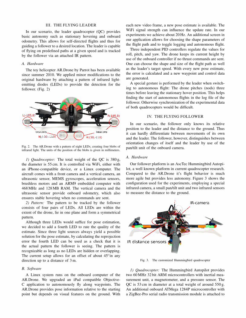
more agile but provides less autonomy. Figure 3 shows the
configuration used for the experiments, employing a special
infrared camera, a small pan/tilt unit and two infrared sensors
to measure the distance to the ground.
Fig. 3. The customized Hummingbird quadrocopter
1) Quadrocopter: The Hummingbird Autopilot provides
two 60 MHz 32 bit ARM microcontrollers with inertial mea-
surement unit, a magnetometer, and a pressure sensor. The
QC is 53 cm in diameter at a total weight of around 550 g.
An additional onboard ATMega 1284P microcontroller with
a ZigBee-Pro serial radio transmission module is attached to

the serial port of the quadrocopter and allows for commu-
nication with the base station over up to 1 km. The micro-
controller also provides digital and analog input/output ports
and an I2C bus to connect additional hardware. Two infrared
distance sensors, one for short range (Sharp GP2D12) and
on for long range (Sharp GP2Y3A003), were additionally
connected to measure the distance to the ground.
2) Wii Remote Camera: The controller of the Nintendo
Wii game console, informally known as Wiimote, includes an
infrared camera, which communicates via I2C and provides
the pixel positions of up to four infrared light sources in the
frame. In our experiments 200 Hz and more were possible. Its
small size of 8× 8× 5mm3 and its weight make the camera
an ideal onboard sensor for small UAVs, and the ready to use
data disburdens online object recognition. The resolution of
1024×768pixels, achieved by eight times subpixel analysis,
as well as additional information such as intensity and size
of the blobs support sufficient recognition abilities.
3) Pan/Tilt Unit: Two miniature servo motors are used as
a minimalistic, lightweight pan/tilt unit. The unit enlarges
the range of operation since the camera can be directed to
the IR-pattern even if the pattern is not directly in front of
the follower. We connected the potentiometer of each servo
motor to an analog input of the microcontroller and defined
a calibration function to estimate the current servo angle
from the voltage measurements. This gives us much more
precise and faster results than estimating the servo position
over time by means of the PWM signal. Experiments have
shown an accuracy of around 1◦. Knowing the exact current
angle allows for fast and efficient centering of the pattern in
the camera frame and ensures exact pose estimation of the
follower relative to the leader.
B. Software
No ground station is required for autonomous flights
since all processing is done on an onboard microcontroller.
However, a base station is used for monitoring, parameter
tuning, and logging. In each cycle of the main control loop
the pose relative to the leader is estimated in six degrees
of freedom (DOF) using the IR camera. The height over
ground is estimated by the IR distance sensors. Then, four
independent, classical proportional-integral-derivative (PID)
controllers pilot the follower via the serial interface to
maintain a constant x,y-position and orientation relative to
the leader as well as a constant height over ground. Currently,
an update rate of 25 Hz is achieved, limited by the amount
of data which is sent to the base station.
1) Pilot: A high-level finite state-machine machine guides
the follower. By utilizing the two IR sensors autonomous
departure, maintaining a desired height, and gentle landing
is possible, even without sight of the pattern. A switch on
the remote control causes the motors to start, takeoff will
be initiated and a constant rise of the desired height up to
1 m follows. The default desired position is fixed 2 m behind
the leader and could be changed by an operator. Landing is
either initiated via the base station, or if the pattern is lost
for more than 20 cycles (almost one second).
2) Pose estimation: Because of the lack of odometry, the
pose of the follower cannot be calculated in world coordi-
nates. Only the pose relative to the leader can be estimated
in 6 DOF by solving the perspective-three-point problem
assigned to our configuration. To obtain more information
about the pose in the world we integrate the data from the
infrared distance sensors in the estimation. The height over
ground is estimated by the IR sensors, depending on the
sensor range, and smoothed by a Kalman filter.
Since the follower should keep the same yaw angle as
the leader, the error of the yaw angle ψ is the difference in
orientation of both QCs.
C. PnP
The problem of calculating the relative pose from a camera
to a set of markers with known positions is known as the
perspective-n-point problem [4]. To solve the problem we
developed our own method to allow real-time processing
even on a microcontroller. By using several constraints given
by the experimental setup, namely the restricted operating
range and the symmetry of the pattern, we could provide
fast evaluation of the pose. We compared our approach to the
one presented in [7]. While showing a comparable accuracy,
our method runs about 20 times faster, yet providing only
one solution and being restricted to the symmetric patterns,
which is appropriate for our application. The pose estimation
method can be run with 40 Hz on the ATMega microcon-
troller, and has proven to be robust and accurate enough for
our experimental setup (see Section V for details). The same
method was implemented for a Gumstix processor which
processes the image and controls a quadrocopter at 60 Hz.
For details see [8].
1) Spot Identification: We use four IR spots as control
points, whose coordinates are given in the coordinate system
of the leader. The Wii Remote camera directly returns the
image coordinates of these points once they are seen by
the camera. It has to be clarified which spot in the image
corresponds to which control point in the leader’s pattern.
Since it can be assumed that the quadrocopter is not in an
upside-down position or behind the pattern, the spots can
simply be sorted by their x coordinate to identify them as
left, middle-left, middle-right and right.
2) Solving the PnP Problem: Given four points of the
leader pattern L, Ml, Mr, R in the leader’s coordinate system
and four corresponding points in the image plane Li, Mli,
Mri, Ri in pixel coordinates.
First, we consider a virtual fifth point M , which is the
center of Ml and Mr. We estimate its projection Mi ≈
Mli+Mri
2 onto the image plane. Then, we use L, M , R
and their corresponding image points to obtain the camera
position P . If only three control points are used, a maximum
of four locations of P are possible [4]. In our case the
operating range is restricted, so the solutions can easily
be narrowed down to the one which represents the actual
position of P . The control points Ml and Mr together with
Mli and Mri are used afterwards to rate the position estimate
by calculating the reprojection error.

By assuming a standard pinhole camera model, whose
focal length f was experimentally determined for the IR
camera, we expand the image coordinates into 3D vectors
setting zLi= zMi
= zRi= f . We calculate a foot M ′
i
of Mi onto the plane through Li, Ri and origin Oi of
the camera coordinate system. Then we define three angles
α = 6 (M ′i , Ri), β = 6 (Li,M
′i) and γ = 6 (M ′
i ,Mi) with6 (A,B) = arccos A·B
|A|·|B| .
R
L
R
L i
i
R
L k
P
Image plane
Fig. 4. Geometric representation of the plane E, where the points L,Rand P are located, the angles α, β, γ, and the image plane.
Consider the plane E through the points L, R and P .
Define a right-handed Cartesian coordinate system with
MLR = L+R2 as origin, y-axis through R and x-axis lying in
E (Fig. 4). Let M ′ be the foot of M onto the plane E. Note
that M ′i equals the projection of M ′ onto the image plane,
which yields 6 (M ′, R) = α. We know that M lies on a
circle l with radius r = d(M,O) = 110mm. This means that
M ′ lies on the projection of the circle, which is a segment
between two extrema Mmin = (−r, 0) and Mmax = (r, 0).We know from the inscribed angle theorem that P lies on a
circle k with center C =(
yR
tan (α+β) , 0)
. Using the inscribed
angle theorem again, we can construct a point B on k such
that the angle between the segments PB and PR equals α.
B is constructed by rotating R around C by 2α. Note that
B is constant for all possible positions of P on k.
Since M ′ lies on the segment PB, we can now describe
P as a function of M ′, or, since yM ′ = 0, as a function
of xM ′ . The task is to find xM ′ . To achieve this, we look
at two things: First, the distance of M to E, which can be
calculated by
d(M,E) = d(M,M ′) =√
r2 − x2M ′ ,
since M lies on l.
Second, we calculate h = am, with a being the length of
segment PM ′ and m = tan γ being the slope of PM in z
direction. The following equation has to hold:
d(M,E) = h
Squaring and plugging in the values lead to:
r2 − x2M ′ = m2· a2
Further expansion yields the quartic polynomial
c4x4 + c3x
3 + c2x2 + c1x+ c0 = 0 (1)
with x = xM ′ − xC and coefficients
c4 = m2 + 1
c3 = 2(xC − xB)
c2 = v + (1 − 2x2C)B2− 4xCxB
c1 = 2(xCB2− vxB)
c0 = vB2 +m2(B2)2,
with v = x2C − r2 and B2 = x2B + y2B .
Since we can assume that the pattern is upright and facing
the follower, the valid solution is the one with M being
closest to the camera, i.e., the largest root of (1) belongs
to the valid solution. This root is found using four iterations
of Newton’s method, starting with x0 = xMmax− xC .
Once the root xr is calculated, P can be determined by
intersecting the line through B and M ′ = (xr + xC , 0)with circle k and transforming its coordinates into the leader
coordinate system.
Singularities appear only if the camera is on the circle
defined by L,M,R, which does not happen in our scenario.
3) Confidence Estimation: A confidence of the pose esti-
mation is calculated using the reprojection error. The current
pose is used to map all four control points L, Ml, Mr
and R into camera space. Then we project the points using
the pinhole camera model from above. The projected points
are finally compared with the actual image points returned
from the camera using the sum of Euclidean distances.
The distance error is converted into a probability using a
Gaussian with an empirically determined standard deviation
of 11 pixels. A perfect shape results in the maximum con-
fidence value of 100 %. The confidence value is used by
Kalman filters, which refine short periods where the pattern
is invisible as well as outliers of the pose estimate for x, y,
z and yaw.
Knowing the camera position P , the follower’s position
can be directly calculated using the transformation matrix of
the pan/tilt unit and the two servo angles.
4) PID Controller: Four independent PID controllers pilot
the follower. The only modification to the controllers de-
scribed in [13] are filters which make the loop more sensitive
if the quadrocopter is near the desired position and less if
the error becomes larger.
V. EXPERIMENTS
We flew multiple times with a single and with both
quadrocopters at the same time to test the performance of
our system. Videos can be found in our YouTube channel1.
A. The Task
The follower had to keep a constant position 2 m behind
the pattern. Since the follower cannot differentiate between
its own movements and those of the leader carrying the
pattern, the leader could fly any path resulting in the other
quadrocopter following. Each orientation change of the
1http://www.youtube.com/user/ZellTuebingen

leader leads to a change in the followers desired position.
This ensures that the sight on the pattern is kept.
Our experience shows, that the leader was influenced by
the wind produced by the follower and we tried to reduce
the effect by choosing a distance between both aircrafts and
a height where the effect is acceptable. First experiments
involve only the Hummingbird and demonstrate the perfor-
mance without any disturbance of another aircraft. To test
stability of the entire system, we further experimented with
both quadrocopters and the leader was flown in different
shapes, orientations and with varying speeds.
B. Shapes
The leader follows waypoints along a given path produced
by the iPad App. The operator can vary the size s, the
speed v, and the type of the shape. Since every dataset
includes a timestamp, the time t since autonomy started can
be calculated. We implemented waypoint navigation for a
line along x or y, circle and an eight-shape.
C. Results
In first experiments, we flew the AR.Drone manually along
a straight path of 30 m back and forth and measured a posi-
tion error of about 5% at the end. The floor was prepared to
provide sufficient image features for the AR.Drone odometer
using printed posters and thus we used the onboard odometry
as ground truth data. For the focus of this work, tracking and
following with another quadrocopter, the position error of the
leader is not critical but only represents the performance of
following the path of a given shape.
1) Only the Follower: In this experiment the follower
did not hover in a stationary position but followed a small
circular path of 80 cm in diameter in front of a fixed pat-
tern, tracked by the NaturalPoint tracking system OptiTrack.
Figure 5 and 6 show a section of the collected data of the
tracking system and the onboard P3P pose estimation as well
as the expected position.
Fig. 5. The recorded path of the Hummingbird flying a circular path infront of a fixed pattern.
Fig. 6. Ten second clip of the recording shown in fig. 5.
TABLE I
PERFORMANCE OF OUR P3P POSE ESTIMATION AND THE PID
CONTROLLER OF THE FOLLOWER. X, Y AND Z IN cm
P3P error Flight accuracyX Y Z X Y Z
Abs. Mean 1.40 1.53 1.67 6.60 5.59 6.37Std. dev. 1.26 1.33 1.51 4.71 4.21 4.46Max. err. 13.83 11.82 12.93 24.3 19.70 24.0
TABLE II
CONTROLLER CHARACTERISTICS OF AUTONOMOUS FLIGHTS OF A
STRAIGHT-LINE PATH OF 1 M LENGTH. X, Y AND Z IN cm, ψ IN ◦
Leader FollowerX Y ψ X Y Z ψ
Mean 4.5 -0.8 0.0 1.9 -0.5 8.2 -0.5Std. dev. 26.2 27.8 0.3 17.4 25.0 18.3 7.5Max. err. 90.8 97.0 1.1 68.4 68.4 61.5 34.3
Table I shows statistics of the errors comparing the P3P
pose estimation with the tracked pose of the tracking system
during the whole experiment.
The absolute mean of less than 17 mm and the relatively
small standard deviation for the pose estimation shows the
stability of our P3P solution and allows the usage of this
estimation as ground truth for experiments outside a track-
ing system, as is done for the following experiments. The
standard deviation and the errors of the flight accuracy show
uncritical oscillation around the desired position, considering
the size of the quadrocopter (53 cm).
2) Straight Line: Table II shows the results of autonomous
flights of both UAVs following a short straight-line path of
1 m length. The path was flown nine times with a given
speed of 20 cm/s in a small room. The short path results in a
relatively harsh start, acceleration and stop sequence. The z-
error of the AR.Drone is not given, because it is controlled
by the aircraft standard hardware and not our controllers.
Figure 7 shows the error (deviation to desired position) of
the follower during this experiment.
Erro
r [
cm
]
-80
-60
-40
-20
0
20
40
60
80
t [s]
0 20 40 60 80 100 120 140
x
y
Fig. 7. Error of the follower flight of a short straight-line path of 1 mlength repeated nine times.
Although the aircrafts were constantly moving, a standard
deviaton of about 25 cm and a maximum error of about 1 m
could be kept. This is sufficient for indoor flights in office
buildings.
3) Circle: Ten successive autonomously flown circles
with a diameter of 2 m at a given speed of 25 cm/s were
flown. The diameter equals the distance to the follower.
An orthogonal orientation of the leader relative to the path
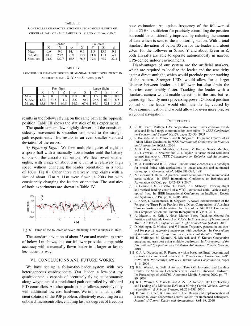
TABLE III
CONTROLLER CHARACTERISTICS OF AUTONOMOUS FLIGHTS OF
CIRCULAR PATH OF 2 M DIAMETER. X, Y AND Z IN cm, ψ IN ◦
Leader FollowerX Y ψ X Y Z ψ
Mean 0.6 0.6 14.4 0.6 1.3 13.5 0.1Std. dev. 18.9 20.7 0.9 13.9 21.8 11.1 4.7Max. err. 94.6 122.7 16.5 76.3 77.4 65.7 22.3
TABLE IV
CONTROLLER CHARACTERISTICS OF MANUAL FLIGHT EXPERIMENTS IN
AN EIGHT-SHAPE. X, Y AND Z IN cm, ψ IN ◦
Fast flight Large flightX Y Z ψ X Y Z ψ
Mean 0.6 0.8 25.8 0.0 0.5 1.5 18.5 0.0S. dev. 18.0 23.5 11.3 8.6 20.1 26.5 16.2 8.5M. err. 95.8 79.4 64.8 34.5 67.6 95.1 72.1 34.5
results in the follower flying on the same path at the opposite
position. Table III shows the statistics of this experiment.The quadrocopters flew slightly slower and the consistent
sideway movement is smoother compared to the straight
path experiments. This results in an even smaller standard
deviation of the errors.
4) Figure-of-Eight: We flew multiple figures-of-eight in
a sports hall with a manually flown leader until the battery
of one of the aircrafts ran empty. We flew seven smaller
eights, with a size of about 5 m x 3 m at a relatively high
speed without changing the leader orientation in a total
of 160 s (Fig 8). Other three relatively large eights with a
size of about 17 m x 11 m were flown in 200 s but with
consistently changing the leaders orientation. The statistics
of both experiments are shown in Table IV.
Err
or
[cm
]
-100
-50
0
50
100
t [s]
0 50 100 150
x
y
Fig. 8. Error of the follower of seven manually flown 8-shapes in 160 s.
The standard deviation of about 25 cm and maximum error
of below 1 m shows, that our follower provides comparable
accuracy with a manually flown leader in a larger or faster,
less accurate way.
VI. CONCLUSIONS AND FUTURE WORKS
We have set up a follow-the-leader system with two
heterogeneous quadrocopters. Our leader, a low-cost toy
quadrocopter is capable of accurately flying autonomously
along waypoints of a predefined path controlled by offboard
PID-controllers. Another quadrocopter follows precisely only
with additional low-cost hardware. We implemented an effi-
cient solution of the P3P problem, effectively executing on an
onboard microcontroller, enabling fast six degrees of freedom
pose estimation. An update frequency of the follower of
about 25 Hz is sufficient for precisely controlling the position
but could be considerably improved by reducing the amount
of data which is sent to the monitoring station. With a total
standard deviation of below 35 cm for the leader and about
20 cm for the follower in X and Y and about 15 cm in Z,
both aircrafts are able to operate autonomously in narrow,
GPS-denied indoor environments.
Disadvantages of our system are the artificial markers,
which are required to localize the leader and the sensitivity
against direct sunlight, which would preclude proper tracking
of the pattern. Stronger LEDs would allow for a larger
distance between leader and follower but also drain the
batteries considerably faster. Tracking the leader with a
standard camera would enable detection in the sun, but re-
quires significantly more processing power. Onboard position
control on the leader would eliminate the lag caused by
WiFi communication and would allow for even more precise
waypoint navigation.
REFERENCES
[1] R. W. Beard: Multiple UAV cooperative search under collision avoid-ance and limited range communication constraints. In IEEE Conference
on Decision and Control (CDC), pages 25–30, 2003[2] S. Bouabdallah, P. Murrieri, and R. Siegwart: Design and Control of an
Indoor Micro Quadrotor. In IEEE International Conference on Robotics
and Automation (ICRA), 2004[3] A. K. Das, Student Member, R. Fierro, V. Kumar, Senior Member,
J.P. Ostrowski, J. Spletzer and C. J. Taylor: A vision-based formationcontrol framework. IEEE Transactions on Robotics and Automation,18:813–825, 2002
[4] M. A. Fischler and R. C. Bolles: Random sample consensus: a paradigmfor model fitting with applications to image analysis and automatedcartography. Commun. ACM, 24(6):381–395, 1981
[5] N. Guenard, T. Hamel: A practical visual servo control for an unmannedaerial vehicle. In: IEEE International Conference on Robotics andAutomation (ICRA), pp. 1342–1348 2007
[6] B. Herisse, F.X. Russotto, T. Hamel, R.E. Mahony: Hovering flightand vertical landing control of a VTOL unmanned aerial vehicle usingoptical flow. In: IEEE International Conference on Intelligent Robotsand Systems (IROS), pp. 801–806 2008
[7] L. Kneip, D. Scaramuzza, R. Siegwart: A Novel Parametrization of thePerspective-Three-Point Problem for a Direct Computation of AbsoluteCamera Position and Orientation. In: Proc. of the 24th IEEE Conferenceon Computer Vision and Pattern Recognition (CVPR), 2011.
[8] A. Masselli, A. Zell: A Novel Marker Based Tracking Method forPosition and Attitude Control of MAVs. In Proceedings of International
Micro Air Vehicle Conference and Flight Competition (IMAV), 2012[9] D. Mellinger, N. Michael, and V. Kumar: Trajectory generation and con-
trol for precise aggressive maneuvers with quadrotors. In Proceedings
of the International Symposium on Experimental Robotics, 2010[10] D. Mellinger, M. Shomin, N. Michael, and V. Kumar: Cooperative
grasping and transport using multiple quadrotors. In Proceedings of the
International Symposium on Distributed Autonomous Robotic Systems,2010
[11] O.A.A. Orqueda and R. Fierro. A vision-based nonlinear decentralizedcontroller for unmanned vehicles. In Robotics and Automation, 2006.
ICRA 2006. Proceedings 2006 IEEE International Conference on, pages1 –6, 2006
[12] K.E. Wenzel, A. Zell: Automatic Take Off, Hovering and LandingControl for Miniature Helicopters with Low-Cost Onboard Hardware.In: Proceedings of AMS’09, Autonome Mobile Systeme 2009, pp. 73–80. 2009
[13] K. E. Wenzel, A. Masselli, and A. Zell: Automatic Take Off, Trackingand Landing of a Miniature UAV on a Moving Carrier Vehicle. Journal
of Intelligent & Robotic Systems, 61:221–238, 2010[14] B. Yun, B. Chen, K. Lum, and T. Lee: Design and implementation of
a leader-follower cooperative control system for unmanned helicopters.Journal of Control Theory and Applications, 8:61–68, 2010