Embed Size (px)
Citation preview
Wide-Area Voltage Control of Dynamic Shunt Compensation using Synchrophasors
Presented by: Mathieu Perron, Hydro-Québec Research Institute (IREQ)
Claude Lafond, Hydro-Québec Research Institute (IREQ)Philippe Cadieux, Hydro-QuébecMarcel Racine, Hydro-QuébecHoussem Akremi, Hydro-Québec
2015 NASPI Work Group Meeting (Chicago, IL)
October 14th, 2015
2
Presentation Overview
> Hydro-Québec and the IREQ Research Institute
> The GLCC Project• Context
• Synchrophasor solution
• R&D Pilot project
• Results and conclusion
Hydro-Québec and the IREQ Research Institute
1
4
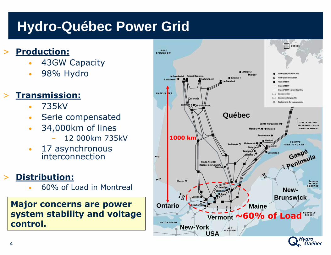
Hydro -Québec Power Grid
Maine
Québec
New-York
Vermont
USA
Ontario
New-Brunswick
Major concerns are power system stability and voltage control.
> Production:• 43GW Capacity
• 98% Hydro
> Transmission:• 735kV
• Serie compensated
• 34,000km of lines – 12 000km 735kV
• 17 asynchronous interconnection
> Distribution:• 60% of Load in Montreal
1000 km
~60% of Load
5
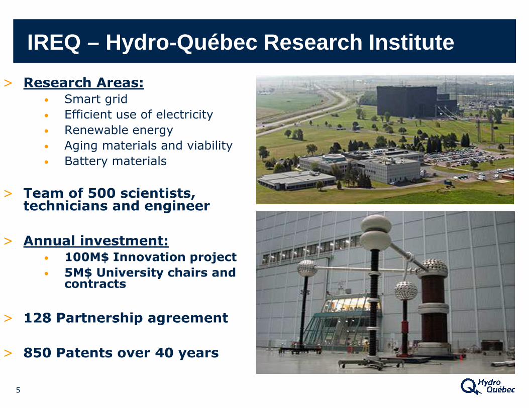
IREQ – Hydro -Québec Research Institute
> Research Areas:• Smart grid
• Efficient use of electricity
• Renewable energy
• Aging materials and viability
• Battery materials
> Team of 500 scientists, technicians and engineer
> Annual investment:• 100M$ Innovation project• 5M$ University chairs and
contracts
> 128 Partnership agreement
> 850 Patents over 40 years
6
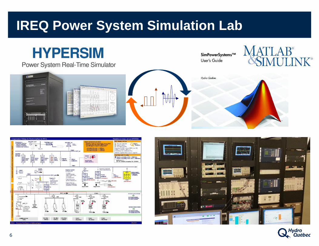
IREQ Power System Simulation Lab
The GLCC Project:
Global and Local Control of Dynamic Shunt Compensator
using Synchrophasors
2
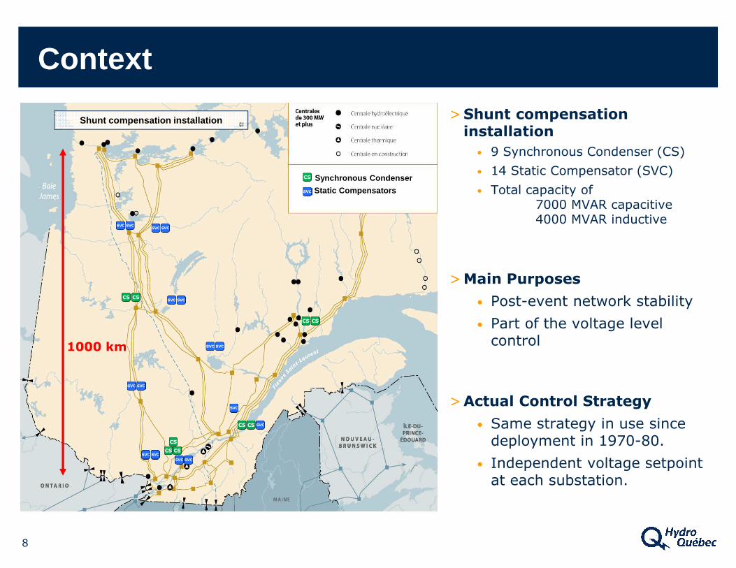
>Shunt compensation installation
• 9 Synchronous Condenser (CS)
• 14 Static Compensator (SVC)
• Total capacity of7000 MVAR capacitive4000 MVAR inductive
>Main Purposes
• Post-event network stability
• Part of the voltage level control
>Actual Control Strategy
• Same strategy in use since deployment in 1970-80.
• Independent voltage setpoint at each substation.
Synchronous Condenser
Static Compensators
Shunt compensation installation
8
Context
1000 km
9
> Contribution of compensators is not optimal because of the topology.
> For a voltage collapse situation in the load area, northern substations would not « see » the voltage drop, and extra MVAR wouldn’t be generated by SVCs.
> Need of a synchronized and robust solution to optimize the use of existing compensators.
Context
VMTL
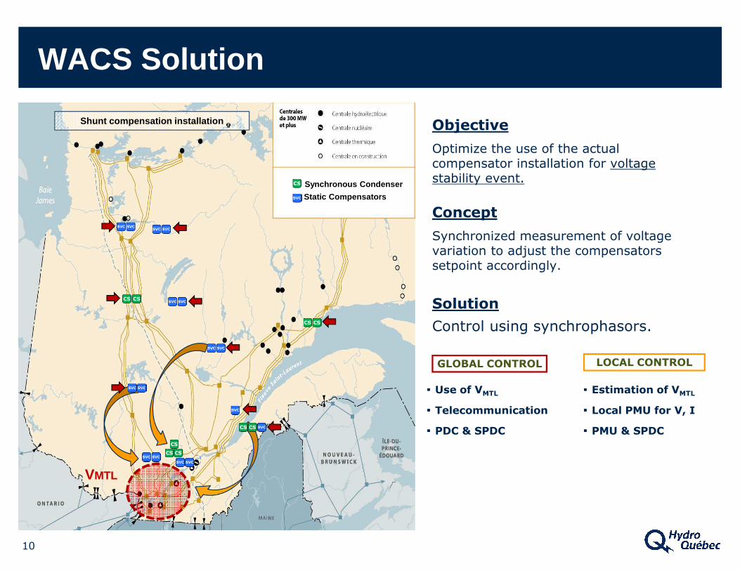
Objective
Optimize the use of the actual compensator installation for voltage stability event.
Concept
Synchronized measurement of voltage variation to adjust the compensators setpoint accordingly.
Solution
Control using synchrophasors.
10
GLOBAL CONTROL LOCAL CONTROL
▪▪▪▪ Use of VMTL
▪▪▪▪ Telecommunication
▪▪▪▪ PDC & SPDC
WACS Solution
Shunt compensation installation
Synchronous Condenser
Static Compensators
▪▪▪▪ Estimation of VMTL
▪▪▪▪ Local PMU for V, I
▪▪▪▪ PMU & SPDC
11
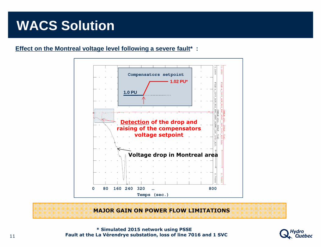
Effect on the Montreal voltage level following a se vere fault* :
Detection of the drop and raising of the compensators
voltage setpoint
Voltage drop in Montreal area
* Simulated 2015 network using PSSEFault at the La Vérendrye substation, loss of line 7016 and 1 SVC
80 160 240 320 … 8000
Temps (sec.)
Compensators setpoint
1.0 PU
1.02 PU*
MAJOR GAIN ON POWER FLOW LIMITATIONS
WACS Solution
VMTL
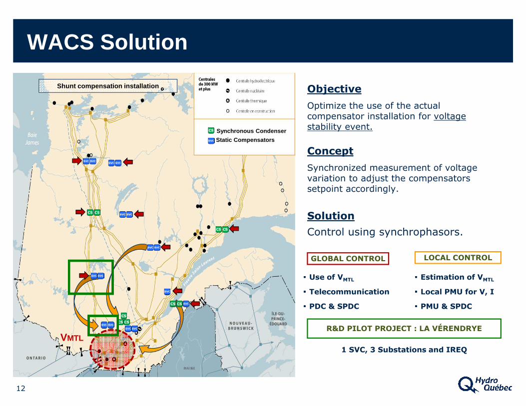
Objective
Optimize the use of the actual compensator installation for voltage stability event.
Concept
Synchronized measurement of voltage variation to adjust the compensators setpoint accordingly.
Solution
Control using synchrophasors.
12
GLOBAL CONTROL LOCAL CONTROL
▪▪▪▪ Use of VMTL
▪▪▪▪ Telecommunication
▪▪▪▪ PDC & SPDC
WACS Solution
Shunt compensation installation
▪▪▪▪ Estimation of VMTL
▪▪▪▪ Local PMU for V, I
▪▪▪▪ PMU & SPDC
R&D PILOT PROJECT : LA VÉRENDRYE
1 SVC, 3 Substations and IREQ
Synchronous Condenser
Static Compensators
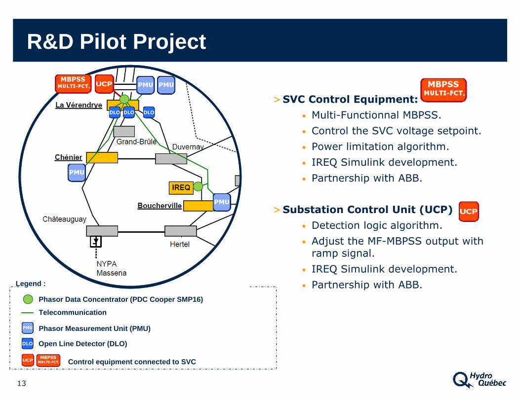
Phasor Data Concentrator (PDC Cooper SMP16)
Telecommunication
>SVC Control Equipment:
• Multi-Functionnal MBPSS.
• Control the SVC voltage setpoint.
• Power limitation algorithm.
• IREQ Simulink development.
• Partnership with ABB.
>Substation Control Unit (UCP)
• Detection logic algorithm.
• Adjust the MF-MBPSS output withramp signal.
• IREQ Simulink development.
• Partnership with ABB.
13
Phasor Measurement Unit (PMU)
Open Line Detector (DLO)
Control equipment connected to SVC
Legend :
R&D Pilot Project
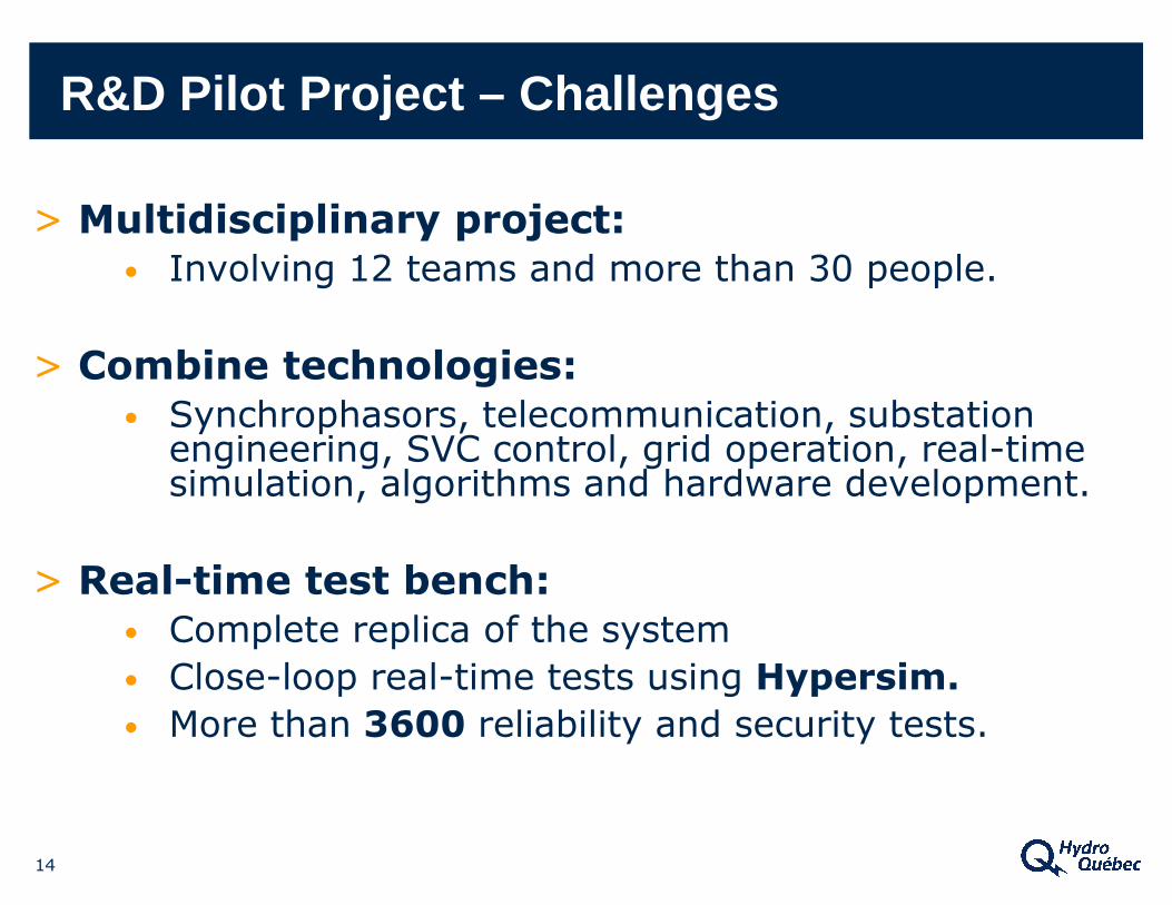
14
> Multidisciplinary project:• Involving 12 teams and more than 30 people.
> Combine technologies:• Synchrophasors, telecommunication, substation
engineering, SVC control, grid operation, real-time simulation, algorithms and hardware development.
> Real-time test bench:• Complete replica of the system
• Close-loop real-time tests using Hypersim.• More than 3600 reliability and security tests.
R&D Pilot Project – Challenges
15
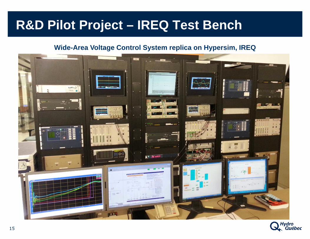
Wide-Area Voltage Control System replica on Hypersi m, IREQ
R&D Pilot Project – IREQ Test Bench
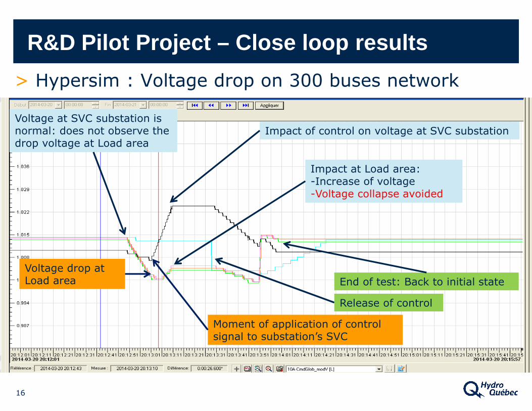
> Hypersim : Voltage drop on 300 buses network
R&D Pilot Project – Close loop results
Voltage at SVC substation is normal: does not observe the drop voltage at Load area
Impact of control on voltage at SVC substation
End of test: Back to initial state
Voltage drop at Load area
Moment of application of control signal to substation’s SVC
Impact at Load area:-Increase of voltage-Voltage collapse avoided
Release of control
16
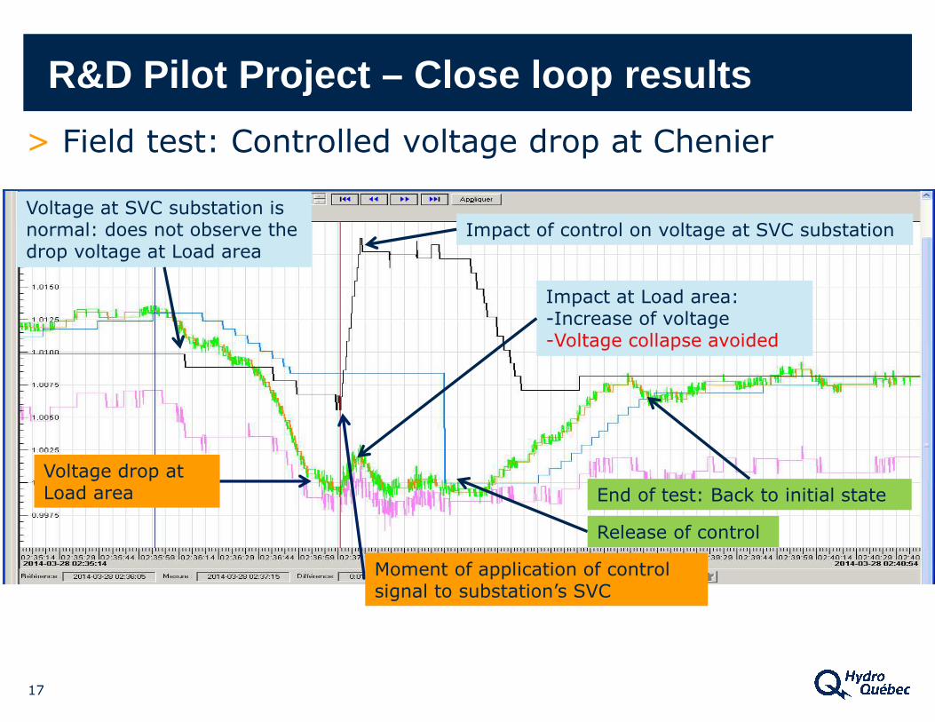
> Field test: Controlled voltage drop at Chenier
17
R&D Pilot Project – Close loop results
Voltage at SVC substation is normal: does not observe the drop voltage at Load area
Impact of control on voltage at SVC substation
End of test: Back to initial state
Voltage drop at Load area
Impact at Load area:-Increase of voltage-Voltage collapse avoided
Release of control
Moment of application of control signal to substation’s SVC
18
Conclusion
> Successful R&D project leading to full WACS deploym ent.
> Voltage profile improved for extreme contingencies.
> Major gains on power flow limitations.
> Low -cost and robust solution using synchrophasors.