Embed Size (px)
Citation preview
JID:AESCTE AID:3068 /FLA [m5G; v 1.134; Prn:10/06/2014; 9:33] P.1 (1-17)
Aerospace Science and Technology ••• (••••) •••–•••
1 67
2 68
3 69
4 70
5 71
6 72
7 73
8 74
9 75
10 76
11 77
12 78
13 79
14 80
15 81
16 82
17 83
18 84
19 85
20 86
21 87
22 88
23 89
24 90
25 91
26 92
27 93
28 94
29 95
30 96
31 97
32 98
33 99
34 100
35 101
36 102
37 103
38
39
40
41
42
43
44
45
46
47
48
49
50
51
52
53
54
55
56
57
58
59
60
61
62
63
64
65
66
Contents lists available at ScienceDirect
Aerospace Science and Technology
www.elsevier.com/locate/aescte
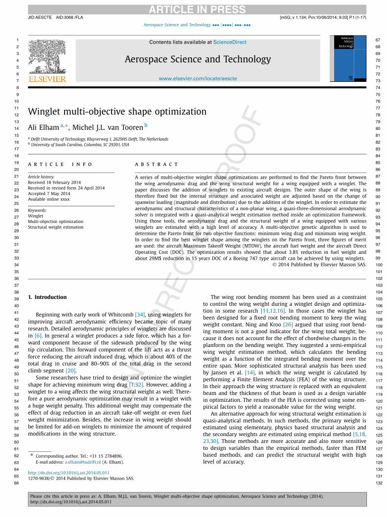
Winglet multi-objective shape optimization
Ali Elham a,∗, Michel J.L. van Tooren b
a Delft University of Technology, Kluyverweg 1, 2629HS Delft, The Netherlandsb University of South Carolina, Columbia, SC 29201, USA
a r t i c l e i n f o a b s t r a c t
Article history:Received 18 February 2014Received in revised form 24 April 2014Accepted 7 May 2014Available online xxxx
Keywords:WingletMulti-objective optimizationStructural weight estimation
A series of multi-objective winglet shape optimizations are performed to find the Pareto front between the wing aerodynamic drag and the wing structural weight for a wing equipped with a winglet. The paper discusses the addition of winglets to existing aircraft designs. The outer shape of the wing is therefore fixed but the internal structure and associated weight are adjusted based on the change of spanwise loading (magnitude and distribution) due to the addition of the winglet. In order to estimate the aerodynamic and structural characteristics of a non-planar wing, a quasi-three-dimensional aerodynamic solver is integrated with a quasi-analytical weight estimation method inside an optimization framework. Using those tools, the aerodynamic drag and the structural weight of a wing equipped with various winglets are estimated with a high level of accuracy. A multi-objective genetic algorithm is used to determine the Pareto front for two objective functions: minimum wing drag and minimum wing weight. In order to find the best winglet shape among the winglets on the Pareto front, three figures of merit are used: the aircraft Maximum Takeoff Weight (MTOW), the aircraft fuel weight and the aircraft Direct Operating Cost (DOC). The optimization results showed that about 3.8% reduction in fuel weight and about 29M$ reduction in 15 years DOC of a Boeing 747 type aircraft can be achieved by using winglets.
© 2014 Published by Elsevier Masson SAS.
104
105
106
107
108
109
110
111
112
113
114
115
116
117
118
119
120
121
122
123
124
125
126
127
128
129
1. Introduction
Beginning with early work of Whitcomb [34], using winglets for improving aircraft aerodynamic efficiency became topic of many research. Detailed aerodynamic principles of winglets are discussed in [6]. In general a winglet produces a side force, which has a for-ward component because of the sidewash produced by the wing tip circulation. This forward component of the lift acts as a thrust force reducing the aircraft induced drag, which is about 40% of the total drag in cruise and 80–90% of the total drag in the second climb segment [20].
Some researchers have tried to design and optimize the winglet shape for achieving minimum wing drag [1,32]. However, adding a winglet to a wing affects the wing structural weight as well. There-fore a pure aerodynamic optimization may result in a winglet with a huge weight penalty. This additional weight may compensate the effect of drag reduction in an aircraft take-off weight or even fuel weight minimization. Besides, the increase in wing weight should be limited for add-on winglets to minimize the amount of required modifications in the wing structure.
* Corresponding author. Tel.: +31 15 2784896.E-mail address: [email protected] (A. Elham).
http://dx.doi.org/10.1016/j.ast.2014.05.0111270-9638/© 2014 Published by Elsevier Masson SAS.
The wing root bending moment has been used as a constraint to control the wing weight during a winglet design and optimiza-tion in some research [11,12,16]. In those cases the winglet has been designed for a fixed root bending moment to keep the wing weight constant. Ning and Kroo [26] argued that using root bend-ing moment is not a good indicator for the wing total weight, be-cause it does not account for the effect of chordwise changes in the planform on the bending weight. They suggested a semi-empirical wing weight estimation method, which calculates the bending weight as a function of the integrated bending moment over the entire span. More sophisticated structural analysis has been used by Jansen et al. [14], in which the wing weight is calculated by performing a Finite Element Analysis (FEA) of the wing structure. In their approach the wing structure is replaced with an equivalent beam and the thickness of that beam is used as a design variable in optimization. The results of the FEA is corrected using some em-pirical factors to yield a reasonable value for the wing weight.
An alternative approach for wing structural weight estimation is quasi-analytical methods. In such methods, the primary weight is estimated using elementary, physics based structural analysis and the secondary weights are estimated using empirical method [5,18,23,30]. Those methods are more accurate and also more sensitive to design variables than the empirical methods, faster than FEM based methods, and can predict the structural weight with high level of accuracy.
130
131
132
JID:AESCTE AID:3068 /FLA [m5G; v 1.134; Prn:10/06/2014; 9:33] P.2 (1-17)
2 A. Elham, M.J.L. van Tooren / Aerospace Science and Technology ••• (••••) •••–•••
1 67
2 68
3 69
4 70
5 71
6 72
7 73
8 74
9 75
10 76
11 77
12 78
13 79
14 80
15 81
16 82
17 83
18 84
19 85
20 86
21
22
23
24
25
26
27
28
29
30
31
32
33
34
35
36
37
38
39
40
41
42
43
44
45
46
47
48
49
50
51
52
53
54
55
56
57
58
59
60
61
62
63
64
65
66
Nomenclature
C wing chordC D wing drag coefficientC Di induced drag coefficientC D p pressure drag coefficientC D f friction drag coefficientCL wing lift coefficientCt wing tip chordC wr winglet root chordd airfoil dragdeff airfoil effective dragl airfoil liftleff airfoil effective liftlw winglet lengthM bending momentMdd drag divergence Mach numbernmax maximum load factor
q dynamic pressureReeff effective Reynolds numberS shear loadS w wing reference areatmax airfoil maximum thicknessV eff effective velocityV∞ free stream velocityα wing angle of attackαi induced angle of attackε wing twist angleεwr winglet root twist angleεwt winglet tip twist angleηt airfoil effective distance coefficientλw winglet taper ratioΛw winglet leading edge sweep angleφw winglet cant angle
87
88
89
90
91
92
93
94
95
96
97
98
99
100
101
102
103
104
105
106
107
108
109
110
111
112
113
114
115
116
117
118
119
120
121
122
123
124
125
126
127
128
129
130
131
132
The main effect of using winglet is the reduction of the wing induced drag. The induced drag can be estimated with a good level of accuracy using a Trefftz plane analysis [25] of the wake behind a wing. This analysis can be done using a Lifting Line (LL) or a Vor-tex Lattice Method (VLM). Therefore in many cases LL or VLM are used to calculate the induced drag. In order to calculate viscous drag strip theory in combination of some semi-empirical relations can be applied [14,26,32,33]. Effect of compressibility (wave drag) is normally ignored. However ignoring some components of drag, or using semi-empirical models may result in unrealistic designs. For example Verstraeten and Slingerland [32] found the optimum winglet height to be about 75% of the semi-span which is an un-realistic design. They discussed that the low level of fidelity aero-dynamic model used by them is the cause of such an unrealistic result.
In the present research the winglet shape has been optimized using aerodynamic and structure models with higher level of ac-curacy. Various components of the wing drag are calculated us-ing a quasi-three-dimensional aerodynamic solver. Instead of using a constraint on the wing root bending moment, the total wing structural weight is estimated using a quasi-analytical weight esti-mation method with high level of accuracy. Using the mentioned solvers a series of multi-objective as well as single-objective opti-mizations are applied to investigate the effect of a winglet on the performance of transonic passenger aircraft.
2. Analysis method
In order to steer the optimization toward more realistic results, a high level of accuracy of the analysis methods is required. On the other hand, the analysis methods should be fast and robust enough to be called hundreds of time during an optimization. The aerodynamic model should accurately estimate both the induced drag and the profile drag of a wing equipped with a winglet. Since the method is to be applied to winglet design for transonic pas-senger aircraft, the compressibility effects should be covered.
In addition, the weight estimation should be performed tak-ing into account the effect of aerodynamic shape on the structural weight, which is necessary for a wing multidisciplinary shape op-timization. The weight model should be able to calculate the wing weight due to all the applied loads: bending, shear and torsion. It is also important to take into account the relief loads due to the wing weight and the fuel weight (for the fuel stored inside the wing).
2.1. Aerodynamic model
A quasi-three-dimensional aerodynamic solver [24] is devel-oped and validated to estimate the wing drag and also the applied loads for structural analysis. The solver is based on strip theory [8]. In this approach the total wing drag is decomposed into two main components: the induced drag and the profile drag. The pro-file drag includes the pressure drag (including the wave drag) and the friction drag. The drag estimation is achieved by a combined use of a VLM to estimate the induced drag and a full potential analysis integrated with the boundary layer model to estimate the profile drag of airfoil sections at several wing spanwise positions.
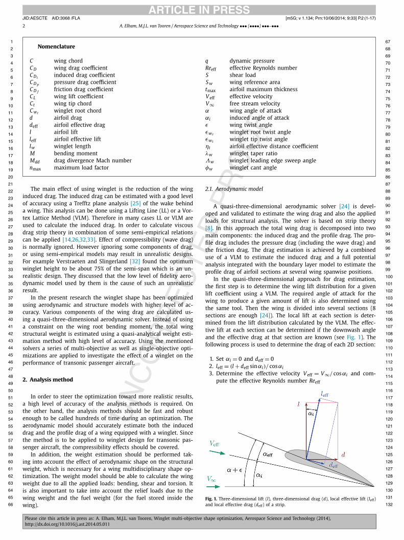
In the quasi-three-dimensional approach for drag estimation, the first step is to determine the wing lift distribution for a given lift coefficient using a VLM. The required angle of attack for the wing to produce a given amount of lift is also determined using the same tool. Then the wing is divided into several sections (8 sections are enough [24]). The local lift at each section is deter-mined from the lift distribution calculated by the VLM. The effec-tive lift at each section can be determined if the downwash angle and the effective drag at that section are known (see Fig. 1). The following process is used to determine the drag of each 2D section:
1. Set αi = 0 and deff = 02. leff = (l + deff sinαi)/ cosαi
3. Determine the effective velocity V eff = V∞/ cosαi and com-pute the effective Reynolds number Reeff
Fig. 1. Three-dimensional lift (l), three-dimensional drag (d), local effective lift (leff) and local effective drag (deff) of a strip.
JID:AESCTE AID:3068 /FLA [m5G; v 1.134; Prn:10/06/2014; 9:33] P.3 (1-17)
A. Elham, M.J.L. van Tooren / Aerospace Science and Technology ••• (••••) •••–••• 3
1 67
2 68
3 69
4 70
5 71
6 72
7 73
8 74
9 75
10 76
11 77
12 78
13 79
14 80
15 81
16 82
17 83
18 84
19 85
20 86
21 87
22 88
23 89
24 90
25 91
26 92
27 93
28 94
29 95
30 96
31 97
32 98
33 99
34 100
35 101
36 102
37 103
38 104
39 105
40 106
41 107
42 108
43 109
44 110
45 111
46 112
47 113
48 114
49 115
50 116
51 117
52 118
53 119
54 120
55 121
56 122
57 123
58 124
59 125
60 126
61 127
62 128
63 129
64 130
65 131
66 132
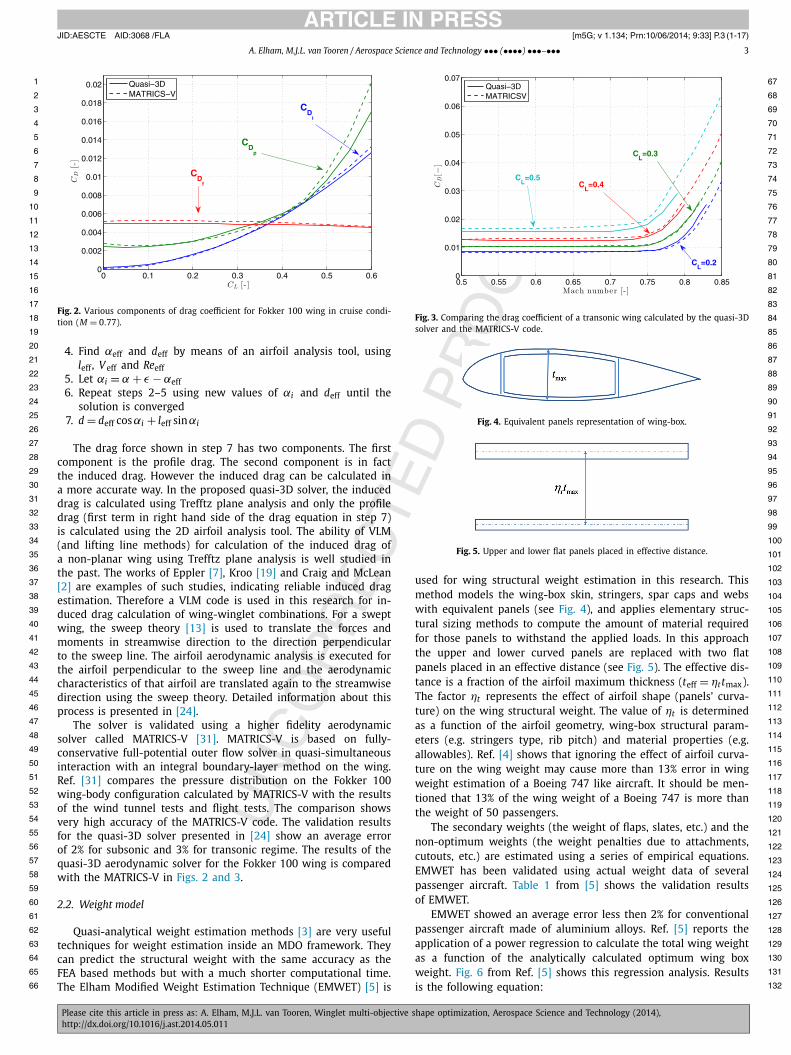
Fig. 2. Various components of drag coefficient for Fokker 100 wing in cruise condi-tion (M = 0.77).
4. Find αeff and deff by means of an airfoil analysis tool, using leff, V eff and Reeff
5. Let αi = α + ε − αeff6. Repeat steps 2–5 using new values of αi and deff until the
solution is converged7. d = deff cosαi + leff sinαi
The drag force shown in step 7 has two components. The first component is the profile drag. The second component is in fact the induced drag. However the induced drag can be calculated in a more accurate way. In the proposed quasi-3D solver, the induced drag is calculated using Trefftz plane analysis and only the profile drag (first term in right hand side of the drag equation in step 7) is calculated using the 2D airfoil analysis tool. The ability of VLM (and lifting line methods) for calculation of the induced drag of a non-planar wing using Trefftz plane analysis is well studied in the past. The works of Eppler [7], Kroo [19] and Craig and McLean [2] are examples of such studies, indicating reliable induced drag estimation. Therefore a VLM code is used in this research for in-duced drag calculation of wing-winglet combinations. For a swept wing, the sweep theory [13] is used to translate the forces and moments in streamwise direction to the direction perpendicular to the sweep line. The airfoil aerodynamic analysis is executed for the airfoil perpendicular to the sweep line and the aerodynamic characteristics of that airfoil are translated again to the streamwise direction using the sweep theory. Detailed information about this process is presented in [24].
The solver is validated using a higher fidelity aerodynamic solver called MATRICS-V [31]. MATRICS-V is based on fully-conservative full-potential outer flow solver in quasi-simultaneous interaction with an integral boundary-layer method on the wing. Ref. [31] compares the pressure distribution on the Fokker 100 wing-body configuration calculated by MATRICS-V with the results of the wind tunnel tests and flight tests. The comparison shows very high accuracy of the MATRICS-V code. The validation results for the quasi-3D solver presented in [24] show an average error of 2% for subsonic and 3% for transonic regime. The results of the quasi-3D aerodynamic solver for the Fokker 100 wing is compared with the MATRICS-V in Figs. 2 and 3.
2.2. Weight model
Quasi-analytical weight estimation methods [3] are very useful techniques for weight estimation inside an MDO framework. They can predict the structural weight with the same accuracy as the FEA based methods but with a much shorter computational time. The Elham Modified Weight Estimation Technique (EMWET) [5] is
Fig. 3. Comparing the drag coefficient of a transonic wing calculated by the quasi-3D solver and the MATRICS-V code.
Fig. 4. Equivalent panels representation of wing-box.
Fig. 5. Upper and lower flat panels placed in effective distance.
used for wing structural weight estimation in this research. This method models the wing-box skin, stringers, spar caps and webs with equivalent panels (see Fig. 4), and applies elementary struc-tural sizing methods to compute the amount of material required for those panels to withstand the applied loads. In this approach the upper and lower curved panels are replaced with two flat panels placed in an effective distance (see Fig. 5). The effective dis-tance is a fraction of the airfoil maximum thickness (teff = ηttmax). The factor ηt represents the effect of airfoil shape (panels’ curva-ture) on the wing structural weight. The value of ηt is determined as a function of the airfoil geometry, wing-box structural param-eters (e.g. stringers type, rib pitch) and material properties (e.g. allowables). Ref. [4] shows that ignoring the effect of airfoil curva-ture on the wing weight may cause more than 13% error in wing weight estimation of a Boeing 747 like aircraft. It should be men-tioned that 13% of the wing weight of a Boeing 747 is more than the weight of 50 passengers.
The secondary weights (the weight of flaps, slates, etc.) and the non-optimum weights (the weight penalties due to attachments, cutouts, etc.) are estimated using a series of empirical equations. EMWET has been validated using actual weight data of several passenger aircraft. Table 1 from [5] shows the validation results of EMWET.
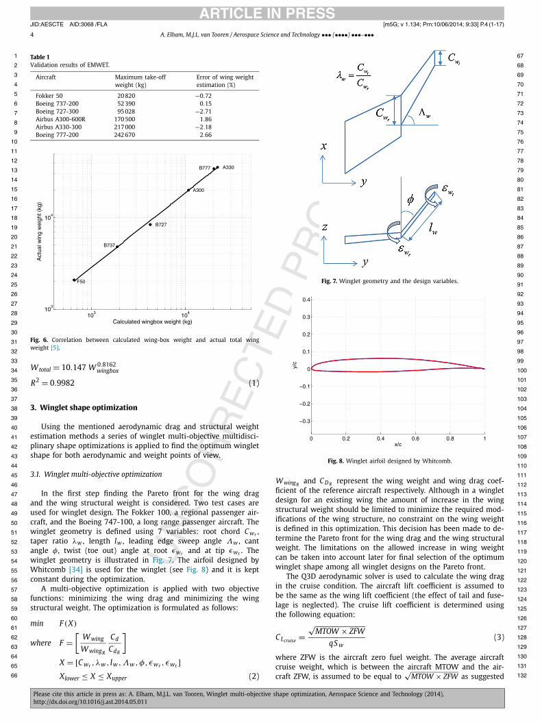
EMWET showed an average error less then 2% for conventional passenger aircraft made of aluminium alloys. Ref. [5] reports the application of a power regression to calculate the total wing weight as a function of the analytically calculated optimum wing box weight. Fig. 6 from Ref. [5] shows this regression analysis. Results is the following equation:
JID:AESCTE AID:3068 /FLA [m5G; v 1.134; Prn:10/06/2014; 9:33] P.4 (1-17)
4 A. Elham, M.J.L. van Tooren / Aerospace Science and Technology ••• (••••) •••–•••
1 67
2 68
3 69
4 70
5 71
6 72
7 73
8 74
9 75
10 76
11 77
12 78
13 79
14 80
15 81
16 82
17 83
18 84
19 85
20 86
21 87
22 88
23 89
24 90
25 91
26 92
27 93
28 94
29 95
30 96
31 97
32 98
33 99
34 100
35 101
36 102
37 103
38 104
39 105
40 106
41 107
42 108
43 109
44 110
45 111
46 112
47 113
48 114
49 115
50 116
51 117
52 118
53 119
54 120
55 121
56 122
57 123
58 124
59 125
60 126
61 127
62 128
63 129
64 130
65 131
66 132
Table 1Validation results of EMWET.
Aircraft Maximum take-off weight (kg)
Error of wing weight estimation (%)
Fokker 50 20 820 −0.72Boeing 737-200 52 390 0.15Boeing 727-300 95 028 −2.71Airbus A300-600R 170 500 1.86Airbus A330-300 217 000 −2.18Boeing 777-200 242 670 2.66
Fig. 6. Correlation between calculated wing-box weight and actual total wing weight [5].
Wtotal = 10.147 W 0.8162wingbox
R2 = 0.9982 (1)
3. Winglet shape optimization
Using the mentioned aerodynamic drag and structural weight estimation methods a series of winglet multi-objective multidisci-plinary shape optimizations is applied to find the optimum winglet shape for both aerodynamic and weight points of view.
3.1. Winglet multi-objective optimization
In the first step finding the Pareto front for the wing drag and the wing structural weight is considered. Two test cases are used for winglet design. The Fokker 100, a regional passenger air-craft, and the Boeing 747-100, a long range passenger aircraft. The winglet geometry is defined using 7 variables: root chord C wr , taper ratio λw , length lw , leading edge sweep angle Λw , cant angle φ, twist (toe out) angle at root εwr and at tip εwt . The winglet geometry is illustrated in Fig. 7. The airfoil designed by Whitcomb [34] is used for the winglet (see Fig. 8) and it is kept constant during the optimization.
A multi-objective optimization is applied with two objective functions: minimizing the wing drag and minimizing the wing structural weight. The optimization is formulated as follows:
min F (X)
where F =[
Wwing
WwingR
Cd
CdR
]
X = [C wr , λw , lw ,Λw , φ, εwr , εwt ]Xlower ≤ X ≤ Xupper (2)
Fig. 7. Winglet geometry and the design variables.
Fig. 8. Winglet airfoil designed by Whitcomb.
WwingRand C D R represent the wing weight and wing drag coef-
ficient of the reference aircraft respectively. Although in a winglet design for an existing wing the amount of increase in the wing structural weight should be limited to minimize the required mod-ifications of the wing structure, no constraint on the wing weight is defined in this optimization. This decision has been made to de-termine the Pareto front for the wing drag and the wing structural weight. The limitations on the allowed increase in wing weight can be taken into account later for final selection of the optimum winglet shape among all winglet designs on the Pareto front.
The Q3D aerodynamic solver is used to calculate the wing drag in the cruise condition. The aircraft lift coefficient is assumed to be the same as the wing lift coefficient (the effect of tail and fuse-lage is neglected). The cruise lift coefficient is determined using the following equation:
CLcruise =√
MTOW × ZFW
qS w(3)
where ZFW is the aircraft zero fuel weight. The average aircraft cruise weight, which is between the aircraft MTOW and the air-craft ZFW, is assumed to be equal to
√MTOW × ZFW as suggested
JID:AESCTE AID:3068 /FLA [m5G; v 1.134; Prn:10/06/2014; 9:33] P.5 (1-17)
A. Elham, M.J.L. van Tooren / Aerospace Science and Technology ••• (••••) •••–••• 5
1 67
2 68
3 69
4 70
5 71
6 72
7 73
8 74
9 75
10 76
11 77
12 78
13 79
14 80
15 81
16 82
17 83
18 84
19 85
20 86
21 87
22 88
23 89
24 90
25 91
26 92
27 93
28 94
29 95
30 96
31
32
33
34
35
36
37
38
39
40
41
42
43
44
45
46
47
48
49
50
51
52
53
54
55
56
57
58
59
60
61
62
63
64
65
66
Table 2Upper and lower bounds for the design variables.
Winglet design variable C wr λw lw Λw φ εwr εwt
Fokker 100 Lower bounds 0.5Cta 0.3 0.5Ct 25◦ 5◦ −0.5◦ −0.5◦
Upper bounds Ct 1 2Ct 45◦ 90◦ −5.5◦ −5.5◦
Boeing 747 Lower bounds 0.5Ctb 0.3 1 m 35◦ 5◦ −0.5◦ −0.5◦
Upper bounds Ct 1 2.5 m 55◦ 90◦ −5.5◦ −5.5◦
a Wing tip chord of Fokker 100 is 1.26 m.b Wing tip chord of Boeing 747 is 4.06 m.
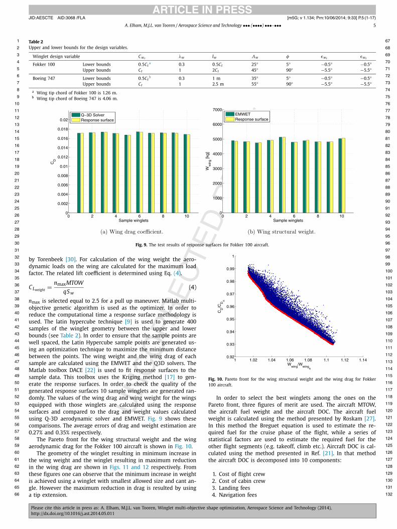
Fig. 9. The test results of response surfaces for Fokker 100 aircraft.
9798
99
100
101
102
103
104
105
106
107
108
109
110
111
112
113
114
115
116
117
118
119
120
121
122
123
124
125
126
127
128
129
130
131
132
by Torenbeek [30]. For calculation of the wing weight the aero-dynamic loads on the wing are calculated for the maximum load factor. The related lift coefficient is determined using Eq. (4).
CLweight = nmaxMTOW
qS w(4)
nmax is selected equal to 2.5 for a pull up maneuver. Matlab multi-objective genetic algorithm is used as the optimizer. In order to reduce the computational time a response surface methodology is used. The latin hypercube technique [9] is used to generate 400 samples of the winglet geometry between the upper and lower bounds (see Table 2). In order to ensure that the sample points are well spaced, the Latin Hypercube sample points are generated us-ing an optimization technique to maximize the minimum distance between the points. The wing weight and the wing drag of each sample are calculated using the EMWET and the Q3D solvers. The Matlab toolbox DACE [22] is used to fit response surfaces to the sample data. This toolbox uses the Kriging method [17] to gen-erate the response surfaces. In order to check the quality of the generated response surfaces 10 sample winglets are generated ran-domly. The values of the wing drag and wing weight for the wings equipped with those winglets are calculated using the response surfaces and compared to the drag and weight values calculated using Q-3D aerodynamic solver and EMWET. Fig. 9 shows these comparisons. The average errors of drag and weight estimation are 0.27% and 0.35% respectively.
The Pareto front for the wing structural weight and the wing aerodynamic drag for the Fokker 100 aircraft is shown in Fig. 10.
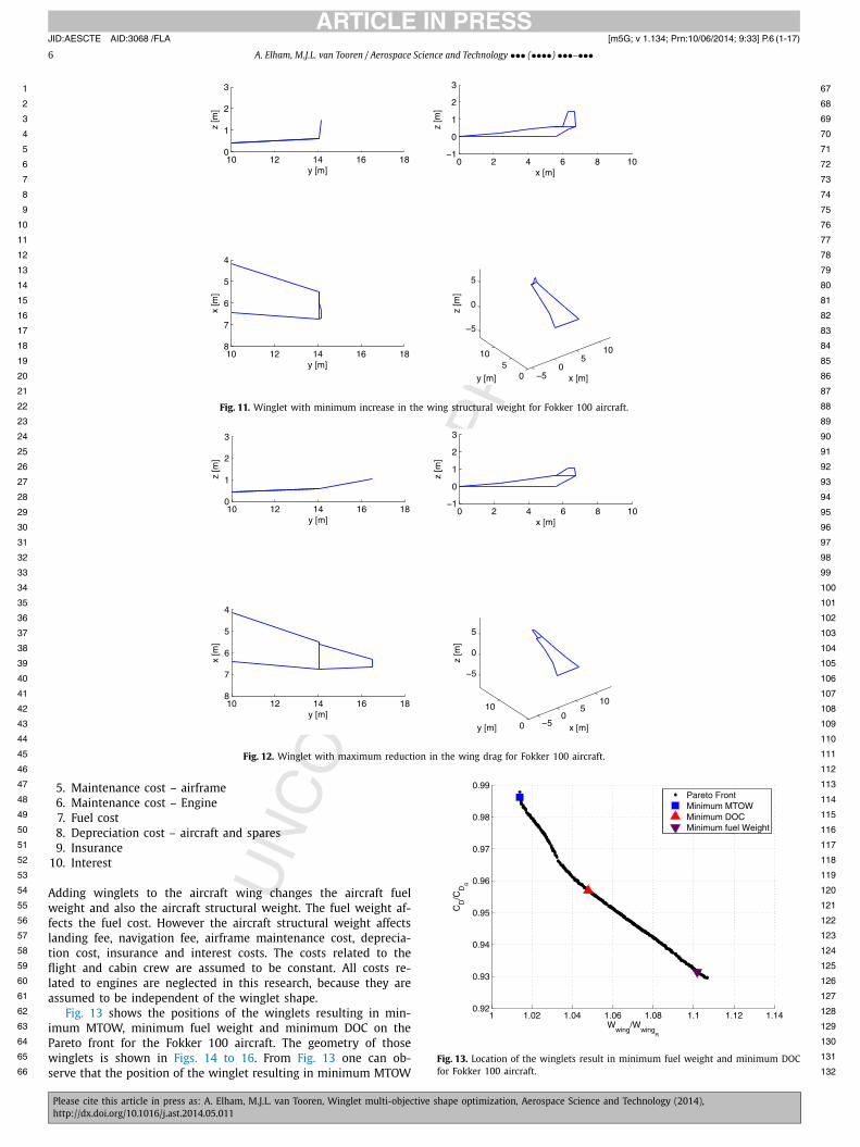
The geometry of the winglet resulting in minimum increase in the wing weight and the winglet resulting in maximum reduction in the wing drag are shown in Figs. 11 and 12 respectively. From these figures one can observe that the minimum increase in weight is achieved using a winglet with smallest allowed size and cant an-gle. However the maximum reduction in drag is resulted by using a tip extension.
Fig. 10. Pareto front for the wing structural weight and the wing drag for Fokker 100 aircraft.
In order to select the best winglets among the ones on the Pareto front, three figures of merit are used. The aircraft MTOW, the aircraft fuel weight and the aircraft DOC. The aircraft fuel weight is calculated using the method presented by Roskam [27]. In this method the Breguet equation is used to estimate the re-quired fuel for the cruise phase of the flight, while a series of statistical factors are used to estimate the required fuel for the other flight segments (e.g. takeoff, climb etc.). Aircraft DOC is cal-culated using the method presented in Ref. [21]. In that method the aircraft DOC is decomposed into 10 components:
1. Cost of flight crew2. Cost of cabin crew3. Landing fees4. Navigation fees
JID:AESCTE AID:3068 /FLA [m5G; v 1.134; Prn:10/06/2014; 9:33] P.6 (1-17)
6 A. Elham, M.J.L. van Tooren / Aerospace Science and Technology ••• (••••) •••–•••
1 67
2 68
3 69
4 70
5 71
6 72
7 73
8 74
9 75
10 76
11 77
12 78
13 79
14 80
15 81
16 82
17 83
18 84
19 85
20 86
21 87
22 88
23 89
24 90
25 91
26 92
27 93
28 94
29 95
30 96
31 97
32 98
33 99
34 100
35 101
36 102
37 103
38 104
39 105
40 106
41 107
42 108
43 109
44 110
45 111
46
47
48
49
50
51
52
53
54
55
56
57
58
59
60
61
62
63
64
65
66
Fig. 11. Winglet with minimum increase in the wing structural weight for Fokker 100 aircraft.
Fig. 12. Winglet with maximum reduction in the wing drag for Fokker 100 aircraft.
1125. Maintenance cost – airframe6. Maintenance cost – Engine7. Fuel cost8. Depreciation cost – aircraft and spares9. Insurance
10. Interest
Adding winglets to the aircraft wing changes the aircraft fuel weight and also the aircraft structural weight. The fuel weight af-fects the fuel cost. However the aircraft structural weight affects landing fee, navigation fee, airframe maintenance cost, deprecia-tion cost, insurance and interest costs. The costs related to the flight and cabin crew are assumed to be constant. All costs re-lated to engines are neglected in this research, because they are assumed to be independent of the winglet shape.
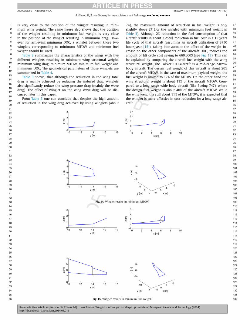
Fig. 13 shows the positions of the winglets resulting in min-imum MTOW, minimum fuel weight and minimum DOC on the Pareto front for the Fokker 100 aircraft. The geometry of those winglets is shown in Figs. 14 to 16. From Fig. 13 one can ob-serve that the position of the winglet resulting in minimum MTOW
113
114
115
116
117
118
119
120
121
122
123
124
125
126
127
128
129
130
131
132Fig. 13. Location of the winglets result in minimum fuel weight and minimum DOC for Fokker 100 aircraft.
JID:AESCTE AID:3068 /FLA [m5G; v 1.134; Prn:10/06/2014; 9:33] P.7 (1-17)
A. Elham, M.J.L. van Tooren / Aerospace Science and Technology ••• (••••) •••–••• 7
1 67
2 68
3 69
4 70
5 71
6 72
7 73
8 74
9 75
10 76
11 77
12 78
13 79
14 80
15 81
16 82
17 83
18 84
19 85
20
21
22
23
24
25
26
27
28
29
30
31
32
33
34
35
36
37
38
39
40
41
42
43
44
45
46
47
48
49
50
51
52
53
54
55
56
57
58
59
60
61
62
63
64
65
66
is very close to the position of the winglet resulting in mini-mum wing weight. The same figure also shows that the position of the winglet resulting in minimum fuel weight is very close to the position of the winglet resulting in minimum drag. How-ever for achieving minimum DOC, a winglet between those two winglets corresponding to minimum MTOW and minimum fuel weight should be used.
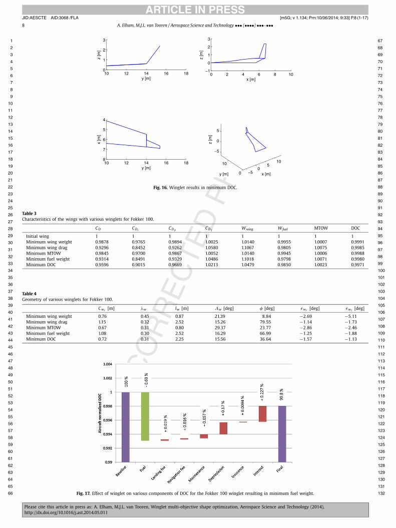
Table 3 summarizes the characteristics of the wings with five different winglets resulting in minimum wing structural weight, minimum wing drag, minimum MTOW, minimum fuel weight and minimum DOC. The geometrical parameters of those winglets are summarized in Table 4.
Table 3 shows, that although the reduction in the wing total drag is mainly achieved by reducing the induced drag, winglets also significantly reduce the wing pressure drag (mainly the wave drag). The effect of winglet on the wing wave drag will be dis-cussed later in this paper.
From Table 3 one can conclude that despite the high amount of reduction in the wing drag achieved by using winglets (about
7%), the maximum amount of reduction in fuel weight is only slightly above 2% (for the winglet with minimum fuel weight in Table 3). Although 2% reduction in the fuel consumption of that aircraft results in about 2.25M$ reduction in fuel cost in a 15 years life cycle of that aircraft (assuming an aircraft utilization of 3750 hours/year [15]), taking into account the effect of the weight in-crease on the other components of the aircraft DOC, reduces the amount of lift cycle cost saving to 660,000$ (see Fig. 17). This can be explained by comparing the aircraft fuel weight with the wing structural weight. The Fokker 100 aircraft is a mid-range narrow body aircraft. The design fuel weight of this aircraft is about 20% of the aircraft MTOW. In the case of maximum payload weight, the fuel weight is limited to 17% of the MTOW. On the other hand the wing structural weight is about 11% of the aircraft MTOW. Com-pared to a long range wide body aircraft (like Boeing 747), where the design fuel weight is about 40% of the aircraft MTOW, while the wing weight is still about 11% of the MTOW, it is expected that the winglet is more effective in cost reduction for a long-range air-craft.
86
87
88
89
90
91
92
93
94
95
96
97
98
99
100
101
102
103
104
105
106
107
108
109
110
111
112
113
114
115
116
117
118
119
120
121
122
123
124
125
126
127
128
129
130
131
132
Fig. 14. Winglet results in minimum MTOW.
Fig. 15. Winglet results in minimum fuel weight.
JID:AESCTE AID:3068 /FLA [m5G; v 1.134; Prn:10/06/2014; 9:33] P.8 (1-17)
8 A. Elham, M.J.L. van Tooren / Aerospace Science and Technology ••• (••••) •••–•••
1 67
2 68
3 69
4 70
5 71
6 72
7 73
8 74
9 75
10 76
11 77
12 78
13 79
14 80
15 81
16 82
17 83
18 84
19 85
20 86
21 87
22 88
23 89
24 90
25 91
26 92
27 93
28 94
29 95
30 96
31 97
32 98
33 99
34 100
35 101
36 102
37 103
38 104
39 105
40 106
41 107
42 108
43 109
44 110
45 111
46 112
47 113
48 114
49 115
50 116
51 117
52 118
53 119
54 120
55 121
56 122
57 123
58 124
59 125
60 126
61 127
62 128
63 129
64 130
65 131
66 132
Fig. 16. Winglet results in minimum DOC.
Table 3Characteristics of the wings with various winglets for Fokker 100.
C D C Di C D p C D f Wwing Wfuel MTOW DOC
Initial wing 1 1 1 1 1 1 1 1Minimum wing weight 0.9878 0.9765 0.9894 1.0025 1.0140 0.9955 1.0007 0.9991Minimum wing drag 0.9296 0.8452 0.9262 1.0580 1.1067 0.9805 1.0075 0.9985Minimum MTOW 0.9845 0.9700 0.9867 1.0052 1.0140 0.9945 1.0006 0.9988Minimum fuel weight 0.9314 0.8491 0.9329 1.0486 1.1018 0.9798 1.0071 0.9980Minimum DOC 0.9596 0.9015 0.9669 1.0213 1.0479 0.9850 1.0023 0.9971
Table 4Geometry of various winglets for Fokker 100.
C wr [m] λw lw [m] Λw [deg] φ [deg] εwr [deg] εwt [deg]
Minimum wing weight 0.76 0.45 0.87 21.39 8.84 −2.69 −5.11Minimum wing drag 1.15 0.32 2.52 15.26 79.55 −1.14 −1.73Minimum MTOW 0.67 0.31 0.80 29.37 23.77 −2.86 −2.46Minimum fuel weight 1.08 0.30 2.52 16.29 66.99 −1.25 −1.88Minimum DOC 0.72 0.31 2.25 15.56 36.64 −1.57 −1.13
Fig. 17. Effect of winglet on various components of DOC for the Fokker 100 winglet resulting in minimum fuel weight.
JID:AESCTE AID:3068 /FLA [m5G; v 1.134; Prn:10/06/2014; 9:33] P.9 (1-17)
A. Elham, M.J.L. van Tooren / Aerospace Science and Technology ••• (••••) •••–••• 9
1 67
2 68
3 69
4 70
5 71
6 72
7 73
8 74
9 75
10 76
11 77
12 78
13 79
14 80
15 81
16 82
17 83
18 84
19 85
20 86
21
22
23
24
25
26
27
28
29
30
31
32
33
34
35
36
37
38
39
40
41
42
43
44
45
46
47
48
49
50
51
52
53
54
55
56
57
58
59
60
61
62
63
64
65
66
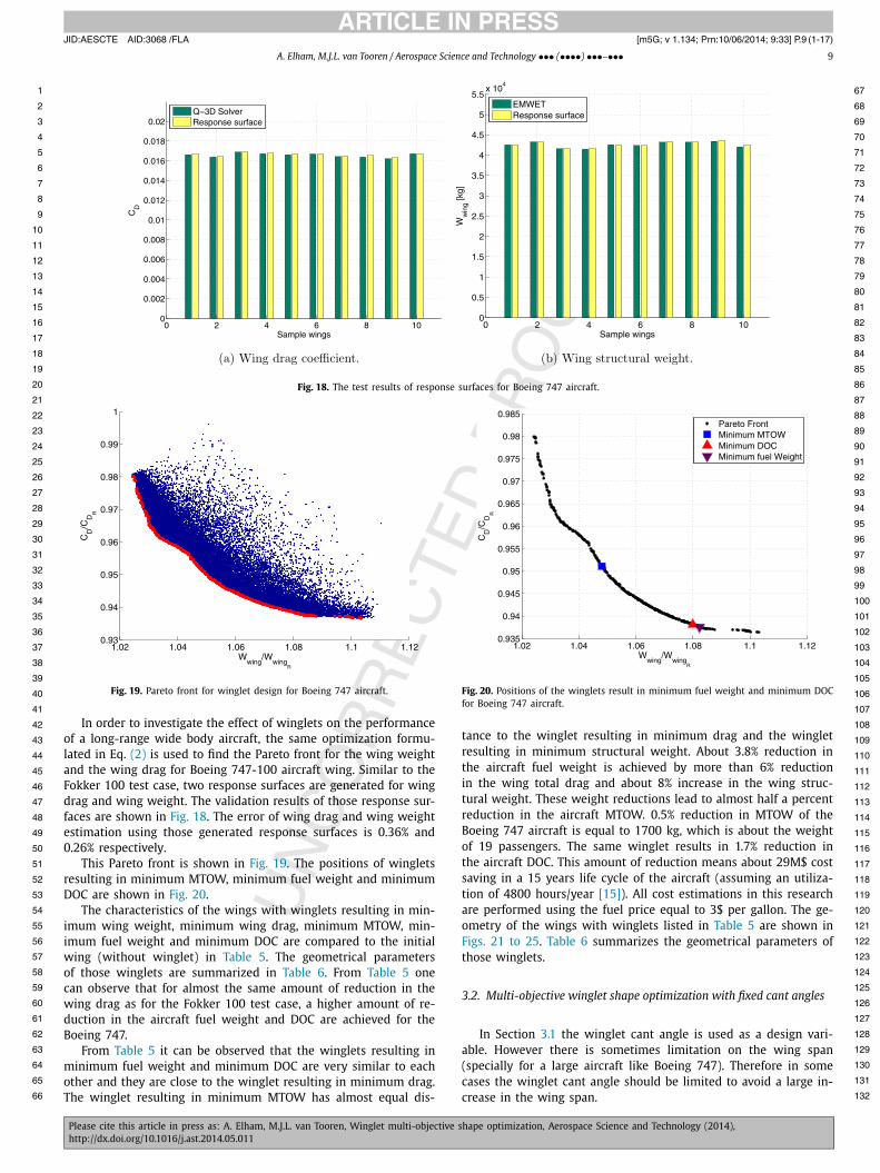
Fig. 18. The test results of response surfaces for Boeing 747 aircraft.
8788
89
90
91
92
93
94
95
96
97
98
99
100
101
102
103
104
105
106
107
108
109
110
111
112
113
114
115
116
117
118
119
120
121
122
123
124
125
126
127
128
129
130
131
132
Fig. 19. Pareto front for winglet design for Boeing 747 aircraft.
In order to investigate the effect of winglets on the performance of a long-range wide body aircraft, the same optimization formu-lated in Eq. (2) is used to find the Pareto front for the wing weight and the wing drag for Boeing 747-100 aircraft wing. Similar to the Fokker 100 test case, two response surfaces are generated for wing drag and wing weight. The validation results of those response sur-faces are shown in Fig. 18. The error of wing drag and wing weight estimation using those generated response surfaces is 0.36% and 0.26% respectively.
This Pareto front is shown in Fig. 19. The positions of winglets resulting in minimum MTOW, minimum fuel weight and minimum DOC are shown in Fig. 20.
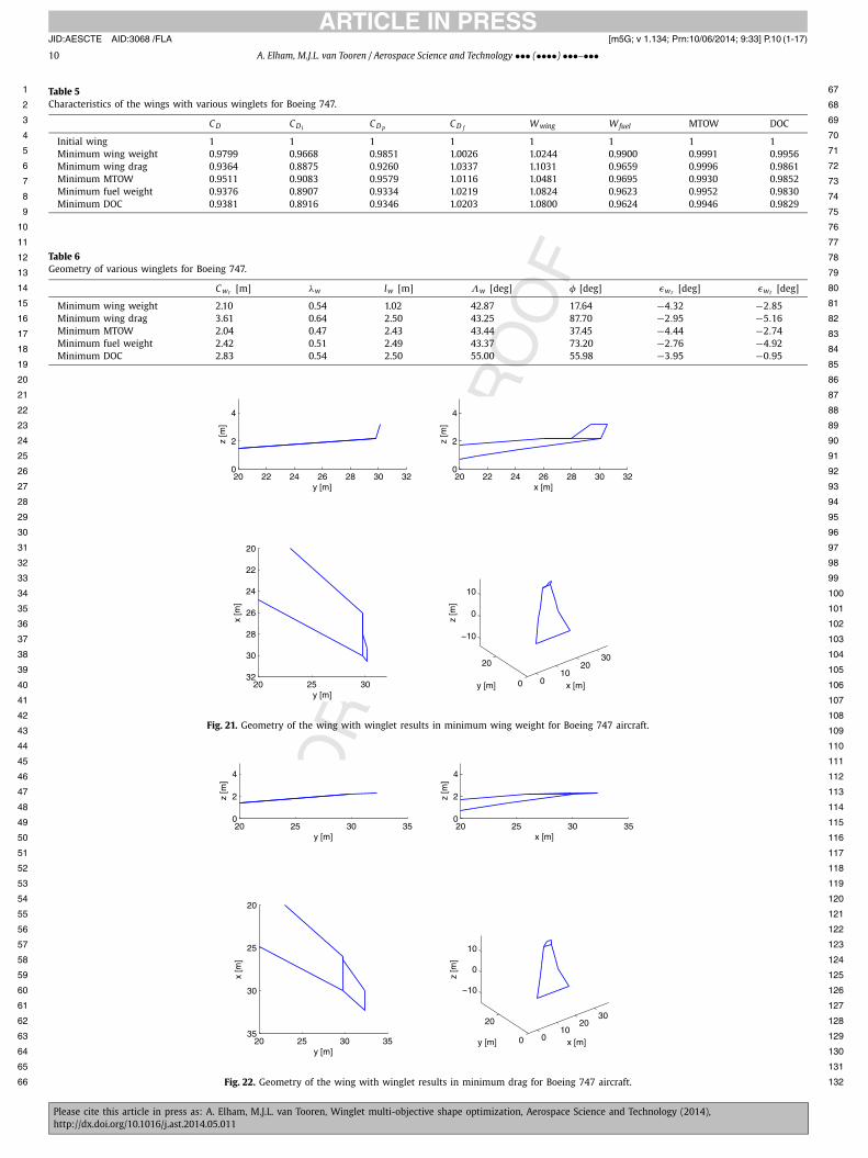
The characteristics of the wings with winglets resulting in min-imum wing weight, minimum wing drag, minimum MTOW, min-imum fuel weight and minimum DOC are compared to the initial wing (without winglet) in Table 5. The geometrical parameters of those winglets are summarized in Table 6. From Table 5 one can observe that for almost the same amount of reduction in the wing drag as for the Fokker 100 test case, a higher amount of re-duction in the aircraft fuel weight and DOC are achieved for the Boeing 747.
From Table 5 it can be observed that the winglets resulting in minimum fuel weight and minimum DOC are very similar to each other and they are close to the winglet resulting in minimum drag. The winglet resulting in minimum MTOW has almost equal dis-
Fig. 20. Positions of the winglets result in minimum fuel weight and minimum DOC for Boeing 747 aircraft.
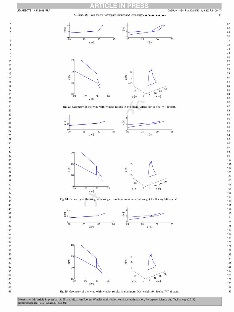
tance to the winglet resulting in minimum drag and the winglet resulting in minimum structural weight. About 3.8% reduction in the aircraft fuel weight is achieved by more than 6% reduction in the wing total drag and about 8% increase in the wing struc-tural weight. These weight reductions lead to almost half a percent reduction in the aircraft MTOW. 0.5% reduction in MTOW of the Boeing 747 aircraft is equal to 1700 kg, which is about the weight of 19 passengers. The same winglet results in 1.7% reduction in the aircraft DOC. This amount of reduction means about 29M$ cost saving in a 15 years life cycle of the aircraft (assuming an utiliza-tion of 4800 hours/year [15]). All cost estimations in this research are performed using the fuel price equal to 3$ per gallon. The ge-ometry of the wings with winglets listed in Table 5 are shown in Figs. 21 to 25. Table 6 summarizes the geometrical parameters of those winglets.
3.2. Multi-objective winglet shape optimization with fixed cant angles
In Section 3.1 the winglet cant angle is used as a design vari-able. However there is sometimes limitation on the wing span (specially for a large aircraft like Boeing 747). Therefore in some cases the winglet cant angle should be limited to avoid a large in-crease in the wing span.
JID:AESCTE AID:3068 /FLA [m5G; v 1.134; Prn:10/06/2014; 9:33] P.10 (1-17)
10 A. Elham, M.J.L. van Tooren / Aerospace Science and Technology ••• (••••) •••–•••
1 67
2 68
3 69
4 70
5 71
6 72
7 73
8 74
9 75
10 76
11 77
12 78
13 79
14 80
15 81
16 82
17 83
18 84
19 85
20 86
21 87
22 88
23 89
24 90
25 91
26 92
27 93
28 94
29 95
30 96
31 97
32 98
33 99
34 100
35 101
36 102
37 103
38 104
39 105
40 106
41 107
42 108
43 109
44 110
45 111
46 112
47 113
48 114
49 115
50 116
51 117
52 118
53 119
54 120
55 121
56 122
57 123
58 124
59 125
60 126
61 127
62 128
63 129
64 130
65 131
66 132
Table 5Characteristics of the wings with various winglets for Boeing 747.
C D C Di C D p C D f Wwing Wfuel MTOW DOC
Initial wing 1 1 1 1 1 1 1 1Minimum wing weight 0.9799 0.9668 0.9851 1.0026 1.0244 0.9900 0.9991 0.9956Minimum wing drag 0.9364 0.8875 0.9260 1.0337 1.1031 0.9659 0.9996 0.9861Minimum MTOW 0.9511 0.9083 0.9579 1.0116 1.0481 0.9695 0.9930 0.9852Minimum fuel weight 0.9376 0.8907 0.9334 1.0219 1.0824 0.9623 0.9952 0.9830Minimum DOC 0.9381 0.8916 0.9346 1.0203 1.0800 0.9624 0.9946 0.9829
Table 6Geometry of various winglets for Boeing 747.
C wr [m] λw lw [m] Λw [deg] φ [deg] εwr [deg] εwt [deg]
Minimum wing weight 2.10 0.54 1.02 42.87 17.64 −4.32 −2.85Minimum wing drag 3.61 0.64 2.50 43.25 87.70 −2.95 −5.16Minimum MTOW 2.04 0.47 2.43 43.44 37.45 −4.44 −2.74Minimum fuel weight 2.42 0.51 2.49 43.37 73.20 −2.76 −4.92Minimum DOC 2.83 0.54 2.50 55.00 55.98 −3.95 −0.95
Fig. 21. Geometry of the wing with winglet results in minimum wing weight for Boeing 747 aircraft.
Fig. 22. Geometry of the wing with winglet results in minimum drag for Boeing 747 aircraft.
JID:AESCTE AID:3068 /FLA [m5G; v 1.134; Prn:10/06/2014; 9:33] P.11 (1-17)
A. Elham, M.J.L. van Tooren / Aerospace Science and Technology ••• (••••) •••–••• 11
1 67
2 68
3 69
4 70
5 71
6 72
7 73
8 74
9 75
10 76
11 77
12 78
13 79
14 80
15 81
16 82
17 83
18 84
19 85
20 86
21 87
22 88
23 89
24 90
25 91
26 92
27 93
28 94
29 95
30 96
31 97
32 98
33 99
34 100
35 101
36 102
37 103
38 104
39 105
40 106
41 107
42 108
43 109
44 110
45 111
46 112
47 113
48 114
49 115
50 116
51 117
52 118
53 119
54 120
55 121
56 122
57 123
58 124
59 125
60 126
61 127
62 128
63 129
64 130
65 131
66 132
Fig. 23. Geometry of the wing with winglet results in minimum MTOW for Boeing 747 aircraft.
Fig. 24. Geometry of the wing with winglet results in minimum fuel weight for Boeing 747 aircraft.
Fig. 25. Geometry of the wing with winglet results in minimum DOC weight for Boeing 747 aircraft.
JID:AESCTE AID:3068 /FLA [m5G; v 1.134; Prn:10/06/2014; 9:33] P.12 (1-17)
12 A. Elham, M.J.L. van Tooren / Aerospace Science and Technology ••• (••••) •••–•••
1 67
2 68
3 69
4 70
5 71
6 72
7 73
8 74
9 75
10 76
11 77
12 78
13 79
14 80
15 81
16 82
17 83
18 84
19 85
20 86
21 87
22 88
23 89
24 90
25 91
26 92
27 93
28 94
29 95
30 96
31 97
32 98
33 99
34 100
35 101
36 102
37 103
38 104
39 105
40 106
41 107
42 108
43 109
44 110
45 111
46 112
47 113
48 114
49 115
50 116
51 117
52 118
53 119
54 120
55 121
56 122
57 123
58 124
59 125
60 126
61 127
62 128
63 129
64 130
65 131
66 132
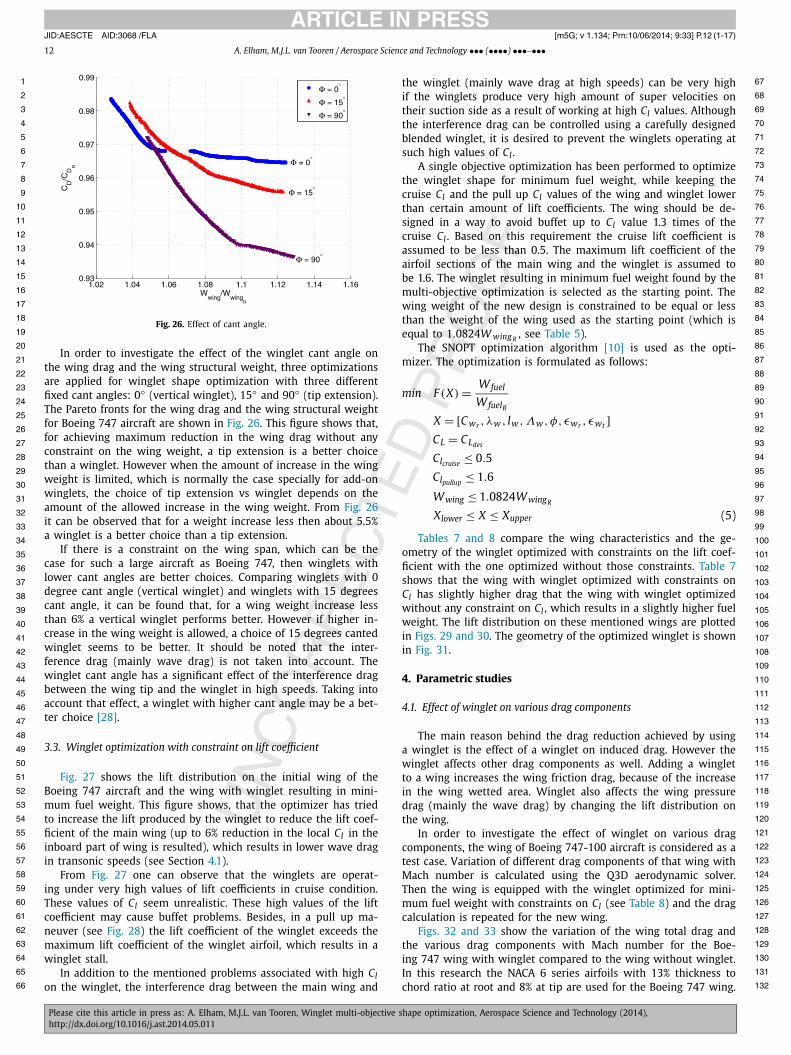
Fig. 26. Effect of cant angle.
In order to investigate the effect of the winglet cant angle on the wing drag and the wing structural weight, three optimizations are applied for winglet shape optimization with three different fixed cant angles: 0◦ (vertical winglet), 15◦ and 90◦ (tip extension). The Pareto fronts for the wing drag and the wing structural weight for Boeing 747 aircraft are shown in Fig. 26. This figure shows that, for achieving maximum reduction in the wing drag without any constraint on the wing weight, a tip extension is a better choice than a winglet. However when the amount of increase in the wing weight is limited, which is normally the case specially for add-on winglets, the choice of tip extension vs winglet depends on the amount of the allowed increase in the wing weight. From Fig. 26it can be observed that for a weight increase less then about 5.5% a winglet is a better choice than a tip extension.
If there is a constraint on the wing span, which can be the case for such a large aircraft as Boeing 747, then winglets with lower cant angles are better choices. Comparing winglets with 0 degree cant angle (vertical winglet) and winglets with 15 degrees cant angle, it can be found that, for a wing weight increase less than 6% a vertical winglet performs better. However if higher in-crease in the wing weight is allowed, a choice of 15 degrees canted winglet seems to be better. It should be noted that the inter-ference drag (mainly wave drag) is not taken into account. The winglet cant angle has a significant effect of the interference drag between the wing tip and the winglet in high speeds. Taking into account that effect, a winglet with higher cant angle may be a bet-ter choice [28].
3.3. Winglet optimization with constraint on lift coefficient
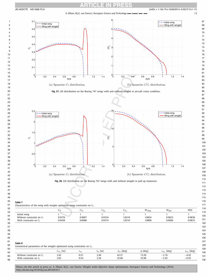
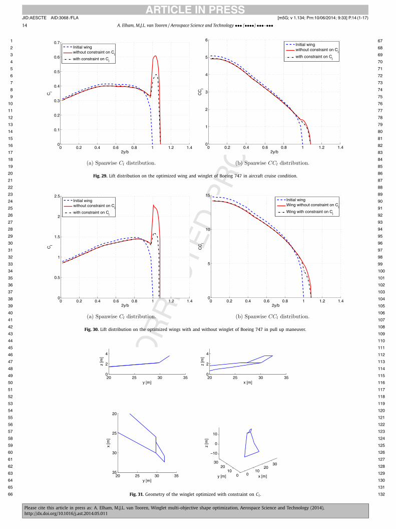
Fig. 27 shows the lift distribution on the initial wing of the Boeing 747 aircraft and the wing with winglet resulting in mini-mum fuel weight. This figure shows, that the optimizer has tried to increase the lift produced by the winglet to reduce the lift coef-ficient of the main wing (up to 6% reduction in the local Cl in the inboard part of wing is resulted), which results in lower wave drag in transonic speeds (see Section 4.1).
From Fig. 27 one can observe that the winglets are operat-ing under very high values of lift coefficients in cruise condition. These values of Cl seem unrealistic. These high values of the lift coefficient may cause buffet problems. Besides, in a pull up ma-neuver (see Fig. 28) the lift coefficient of the winglet exceeds the maximum lift coefficient of the winglet airfoil, which results in a winglet stall.
In addition to the mentioned problems associated with high Clon the winglet, the interference drag between the main wing and
the winglet (mainly wave drag at high speeds) can be very high if the winglets produce very high amount of super velocities on their suction side as a result of working at high Cl values. Although the interference drag can be controlled using a carefully designed blended winglet, it is desired to prevent the winglets operating at such high values of Cl .
A single objective optimization has been performed to optimize the winglet shape for minimum fuel weight, while keeping the cruise Cl and the pull up Cl values of the wing and winglet lower than certain amount of lift coefficients. The wing should be de-signed in a way to avoid buffet up to Cl value 1.3 times of the cruise Cl . Based on this requirement the cruise lift coefficient is assumed to be less than 0.5. The maximum lift coefficient of the airfoil sections of the main wing and the winglet is assumed to be 1.6. The winglet resulting in minimum fuel weight found by the multi-objective optimization is selected as the starting point. The wing weight of the new design is constrained to be equal or less than the weight of the wing used as the starting point (which is equal to 1.0824W wing R
, see Table 5).The SNOPT optimization algorithm [10] is used as the opti-
mizer. The optimization is formulated as follows:
min F (X) = Wfuel
WfuelR
X = [C wr , λw , lw ,Λw , φ, εwr , εwt ]CL = CLdes
Clcruise ≤ 0.5
Clpullup≤ 1.6
Wwing ≤ 1.0824WwingR
Xlower ≤ X ≤ Xupper (5)
Tables 7 and 8 compare the wing characteristics and the ge-ometry of the winglet optimized with constraints on the lift coef-ficient with the one optimized without those constraints. Table 7shows that the wing with winglet optimized with constraints on Cl has slightly higher drag that the wing with winglet optimized without any constraint on Cl , which results in a slightly higher fuel weight. The lift distribution on these mentioned wings are plotted in Figs. 29 and 30. The geometry of the optimized winglet is shown in Fig. 31.
4. Parametric studies
4.1. Effect of winglet on various drag components
The main reason behind the drag reduction achieved by using a winglet is the effect of a winglet on induced drag. However the winglet affects other drag components as well. Adding a winglet to a wing increases the wing friction drag, because of the increase in the wing wetted area. Winglet also affects the wing pressure drag (mainly the wave drag) by changing the lift distribution on the wing.
In order to investigate the effect of winglet on various drag components, the wing of Boeing 747-100 aircraft is considered as a test case. Variation of different drag components of that wing with Mach number is calculated using the Q3D aerodynamic solver. Then the wing is equipped with the winglet optimized for mini-mum fuel weight with constraints on Cl (see Table 8) and the drag calculation is repeated for the new wing.
Figs. 32 and 33 show the variation of the wing total drag and the various drag components with Mach number for the Boe-ing 747 wing with winglet compared to the wing without winglet. In this research the NACA 6 series airfoils with 13% thickness to chord ratio at root and 8% at tip are used for the Boeing 747 wing.
JID:AESCTE AID:3068 /FLA [m5G; v 1.134; Prn:10/06/2014; 9:33] P.13 (1-17)
A. Elham, M.J.L. van Tooren / Aerospace Science and Technology ••• (••••) •••–••• 13
1 67
2 68
3 69
4 70
5 71
6 72
7 73
8 74
9 75
10 76
11 77
12 78
13 79
14 80
15 81
16 82
17 83
18 84
19 85
20 86
21 87
22 88
23 89
24 90
25 91
26 92
27 93
28 94
29 95
30 96
31 97
32 98
33 99
34 100
35 101
36 102
37 103
38 104
39 105
40 106
41 107
42 108
43 109
44 110
45 111
46 112
47 113
48 114
49 115
50 116
51 117
52 118
53 119
54 120
55 121
56 122
57 123
58 124
59 125
60 126
61 127
62 128
63 129
64 130
65 131
66 132
Fig. 27. Lift distribution on the Boeing 747 wings with and without winglet in aircraft cruise condition.
Fig. 28. Lift distribution on the Boeing 747 wings with and without winglet in pull up maneuver.
Table 7Characteristics of the wing with winglet optimized using constraints on Cl .
C D C Di C D p C D f Wwing Wfuel DOC
Initial wing 1 1 1 1 1 1 1Without constraint on Cl 0.9376 0.8907 0.9334 1.0219 1.0824 0.9623 0.9838With constraint on Cl 0.9438 0.8988 0.9374 1.0210 1.0808 0.9666 0.9833
Table 8Geometrical parameters of the winglet optimized using constraints on Cl .
C wr [m] λw lw [m] Λw [deg] φ [deg] εwr [deg] εwt [deg]
Without constraint on Cl 2.42 0.51 2.49 43.37 73.20 −2.76 −4.92With constraint on Cl 2.83 0.54 2.50 55.00 55.98 −3.95 −0.95
JID:AESCTE AID:3068 /FLA [m5G; v 1.134; Prn:10/06/2014; 9:33] P.14 (1-17)
14 A. Elham, M.J.L. van Tooren / Aerospace Science and Technology ••• (••••) •••–•••
1 67
2 68
3 69
4 70
5 71
6 72
7 73
8 74
9 75
10 76
11 77
12 78
13 79
14 80
15 81
16 82
17 83
18 84
19 85
20 86
21 87
22 88
23 89
24 90
25 91
26 92
27 93
28 94
29 95
30 96
31 97
32 98
33 99
34 100
35 101
36 102
37 103
38 104
39 105
40 106
41 107
42 108
43 109
44 110
45 111
46 112
47 113
48 114
49 115
50 116
51 117
52 118
53 119
54 120
55 121
56 122
57 123
58 124
59 125
60 126
61 127
62 128
63 129
64 130
65 131
66 132
Fig. 29. Lift distribution on the optimized wing and winglet of Boeing 747 in aircraft cruise condition.
Fig. 30. Lift distribution on the optimized wings with and without winglet of Boeing 747 in pull up maneuver.
Fig. 31. Geometry of the winglet optimized with constraint on Cl .
JID:AESCTE AID:3068 /FLA [m5G; v 1.134; Prn:10/06/2014; 9:33] P.15 (1-17)
A. Elham, M.J.L. van Tooren / Aerospace Science and Technology ••• (••••) •••–••• 15
1 67
2 68
3 69
4 70
5 71
6 72
7 73
8 74
9 75
10 76
11 77
12 78
13 79
14 80
15 81
16 82
17 83
18 84
19 85
20 86
21 87
22 88
23 89
24 90
25 91
26 92
27 93
28 94
29 95
30 96
31 97
32 98
33 99
34 100
35 101
36 102
37 103
38 104
39 105
40 106
41 107
42 108
43 109
44 110
45 111
46 112
47 113
48 114
49 115
50 116
51 117
52 118
53 119
54 120
55 121
56 122
57 123
58 124
59 125
60 126
61 127
62 128
63 129
64 130
65 131
66 132
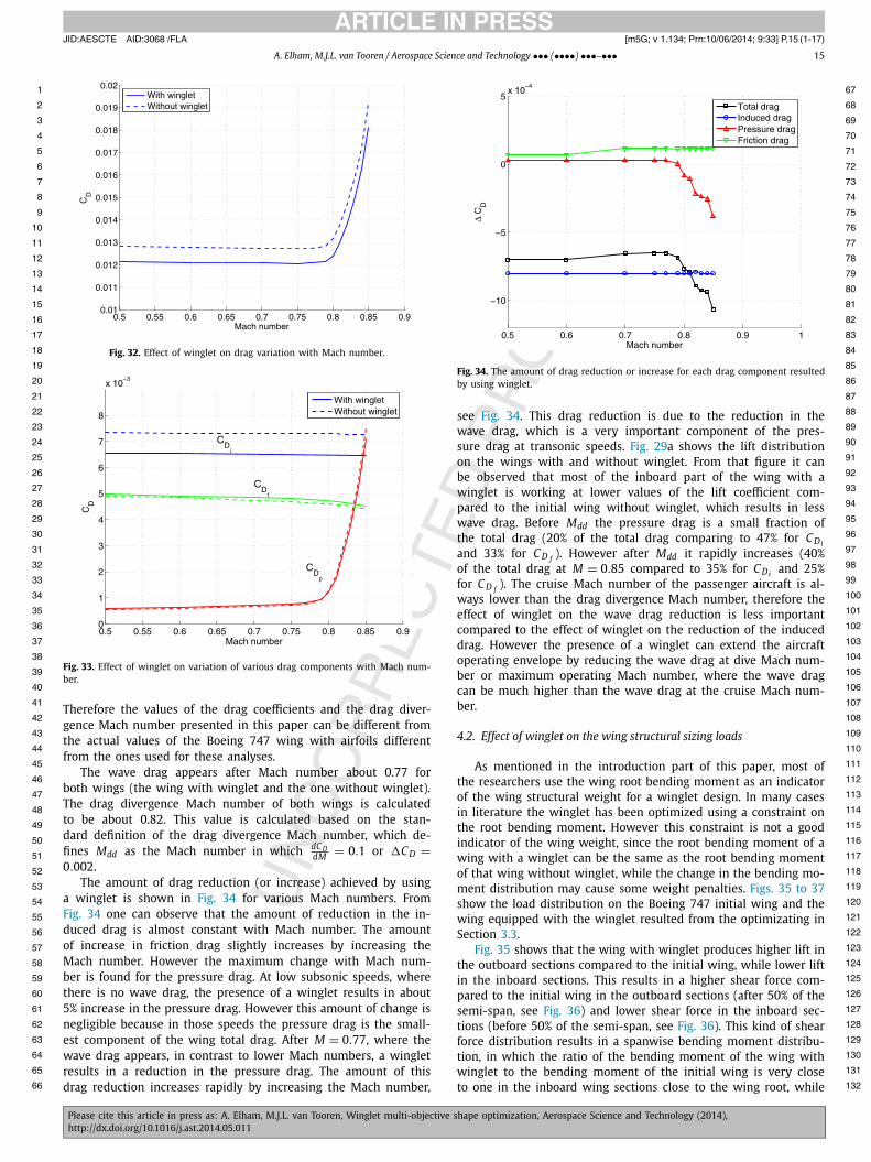
Fig. 32. Effect of winglet on drag variation with Mach number.
Fig. 33. Effect of winglet on variation of various drag components with Mach num-ber.
Therefore the values of the drag coefficients and the drag diver-gence Mach number presented in this paper can be different from the actual values of the Boeing 747 wing with airfoils different from the ones used for these analyses.
The wave drag appears after Mach number about 0.77 for both wings (the wing with winglet and the one without winglet). The drag divergence Mach number of both wings is calculated to be about 0.82. This value is calculated based on the stan-dard definition of the drag divergence Mach number, which de-fines Mdd as the Mach number in which dC D
dM = 0.1 or �C D =0.002.
The amount of drag reduction (or increase) achieved by using a winglet is shown in Fig. 34 for various Mach numbers. From Fig. 34 one can observe that the amount of reduction in the in-duced drag is almost constant with Mach number. The amount of increase in friction drag slightly increases by increasing the Mach number. However the maximum change with Mach num-ber is found for the pressure drag. At low subsonic speeds, where there is no wave drag, the presence of a winglet results in about 5% increase in the pressure drag. However this amount of change is negligible because in those speeds the pressure drag is the small-est component of the wing total drag. After M = 0.77, where the wave drag appears, in contrast to lower Mach numbers, a winglet results in a reduction in the pressure drag. The amount of this drag reduction increases rapidly by increasing the Mach number,
Fig. 34. The amount of drag reduction or increase for each drag component resulted by using winglet.
see Fig. 34. This drag reduction is due to the reduction in the wave drag, which is a very important component of the pres-sure drag at transonic speeds. Fig. 29a shows the lift distribution on the wings with and without winglet. From that figure it can be observed that most of the inboard part of the wing with a winglet is working at lower values of the lift coefficient com-pared to the initial wing without winglet, which results in less wave drag. Before Mdd the pressure drag is a small fraction of the total drag (20% of the total drag comparing to 47% for C Di
and 33% for C D f ). However after Mdd it rapidly increases (40% of the total drag at M = 0.85 compared to 35% for C Di and 25% for C D f ). The cruise Mach number of the passenger aircraft is al-ways lower than the drag divergence Mach number, therefore the effect of winglet on the wave drag reduction is less important compared to the effect of winglet on the reduction of the induced drag. However the presence of a winglet can extend the aircraft operating envelope by reducing the wave drag at dive Mach num-ber or maximum operating Mach number, where the wave drag can be much higher than the wave drag at the cruise Mach num-ber.
4.2. Effect of winglet on the wing structural sizing loads
As mentioned in the introduction part of this paper, most of the researchers use the wing root bending moment as an indicator of the wing structural weight for a winglet design. In many cases in literature the winglet has been optimized using a constraint on the root bending moment. However this constraint is not a good indicator of the wing weight, since the root bending moment of a wing with a winglet can be the same as the root bending moment of that wing without winglet, while the change in the bending mo-ment distribution may cause some weight penalties. Figs. 35 to 37show the load distribution on the Boeing 747 initial wing and the wing equipped with the winglet resulted from the optimizating in Section 3.3.
Fig. 35 shows that the wing with winglet produces higher lift in the outboard sections compared to the initial wing, while lower lift in the inboard sections. This results in a higher shear force com-pared to the initial wing in the outboard sections (after 50% of the semi-span, see Fig. 36) and lower shear force in the inboard sec-tions (before 50% of the semi-span, see Fig. 36). This kind of shear force distribution results in a spanwise bending moment distribu-tion, in which the ratio of the bending moment of the wing with winglet to the bending moment of the initial wing is very close to one in the inboard wing sections close to the wing root, while

JID:AESCTE AID:3068 /FLA [m5G; v 1.134; Prn:10/06/2014; 9:33] P.16 (1-17)
16 A. Elham, M.J.L. van Tooren / Aerospace Science and Technology ••• (••••) •••–•••
1 67
2 68
3 69
4 70
5 71
6 72
7 73
8 74
9 75
10 76
11 77
12 78
13 79
14 80
15 81
16 82
17 83
18 84
19 85
20 86
21 87
22 88
23 89
24 90
25 91
26 92
27 93
28 94
29 95
30 96
31 97
32 98
33 99
34 100
35 101
36 102
37 103
38 104
39 105
40 106
41 107
42 108
43 109
44 110
45 111
46 112
47 113
48 114
49 115
50 116
51 117
52 118
53 119
54 120
55 121
56 122
57 123
58 124
59 125
60 126
61 127
62 128
63 129
64 130
65 131
66 132
Fig. 35. Spanwise lift distribution in a pull up maneuver.
Fig. 36. Spanwise shear force distribution in a pull up maneuver.
Fig. 37. Spanwise bending moment distribution in a pull up maneuver.
much higher than one in the outboard wing sections. The ratio of the shear force and bending moment of the wing with winglet to those ones for the initial wing is plotted in Figs. 38 and 39 as a function of the wing spanwise position.
Fig. 38. Ratio of the shear force of the wing with winglet to the shear force of the reference wing.
Fig. 39. Ratio of the bending moment of the wing with winglet to the bending moment of the reference wing.
The root bending moment of the wing with winglet is just 1.0014 times of the root bending moment of the reference (ini-tial) wing, while the total wing weight of that wing is more than 8% higher than the wing weight of the initial wing. This simple analysis shows that, using a constraint on the wing root bending moment is not enough to control the wing structural weight in a winglet design and optimization.
5. Conclusions
The use of optimization techniques for design of winglets for existing aircraft designs is showed in this paper. A series of multi-objective and single-objective optimizations has been applied to optimize the winglet shape for a mid-range and a long-range pas-senger aircraft. The outer shape of the wings are kept fixed but the internal structure and associated weight is adjusted based on the change of spanwise loading (magnitude and distribution) due to the addition of the winglet. The results of the optimizations show that, although the amount of drag reduction achieved by us-ing winglets is almost the same for both the test case aircraft, the amount of fuel saving resulting from the application of a winglet is more considerable for a wide body long range aircraft. The main reason is the difference between the ratio of the fuel weight to the MTOW and the wing structural weight to the MTOW. In a narrow-body short to medium range aircraft those ratios are close to each
JID:AESCTE AID:3068 /FLA [m5G; v 1.134; Prn:10/06/2014; 9:33] P.17 (1-17)
A. Elham, M.J.L. van Tooren / Aerospace Science and Technology ••• (••••) •••–••• 17
1 67
2 68
3 69
4 70
5 71
6 72
7 73
8 74
9 75
10 76
11 77
12 78
13 79
14 80
15 81
16 82
17 83
18 84
19 85
20 86
21 87
22 88
23 89
24 90
25 91
26 92
27 93
28 94
29 95
30 96
31 97
32 98
33 99
34 100
35 101
36 102
37 103
38 104
39 105
40 106
41 107
42 108
43 109
44 110
45 111
46 112
47 113
48 114
49 115
50 116
51 117
52 118
53 119
54 120
55 121
56 122
57 123
58 124
59 125
60 126
61 127
62
63
64
65
66
other, however in a wide-body long range aircraft, the fuel weight is much higher than the wing structural weight.
The cost analysis showed that, although reducing the fuel weight by using winglets will result in lower fuel cost, the in-creased wing weight due to the presence of a winglet increases some other components of the aircraft DOC. This increase may compensate the effect of winglet on the fuel cost reduction for small aircraft, where the fuel weight is in the same order of mag-nitude as the wing structural weight. However for long range pas-senger aircraft, the use of winglets may result in a DOC reduction about 2%.
A quasi-three dimensional aerodynamic solver is used to calcu-late the wing drag. Using this solver various drag components can be calculated separately. Therefore the effect of winglets on dif-ferent drag components was investigated. This study showed that the winglet can result in a high amount of wave drag reduction at high speeds by reducing the lift coefficient on the wing inboard sections.
In this research a quasi-analytical wing weight estimation method has been used to estimate the wing structural weight. Instead of using constraints on the wing root bending moment, which is a popular approach in winglet optimization, the winglet shape is optimized directly for minimum wing structural weight. This research has showed that using the maximum root bending moment as indicator of the wing total structural weight is not a good approach for winglet multidisciplinary design optimiza-tion. An example was provided to show that although by a careful winglet design the root bending moment can be very close or even equal to the root bending moment of the wing without winglet, the changes in the bending moment distribution may result in a non-negligible amount of weight increase.
Eventually some recommendations are provided for future re-search. As shown in Fig. 7, there is a hard corner between the wing and winglet. In terms of interference drag this seems un-desirable. A design resembling a blended winglet’s geometry is recommended for further research. The second consideration in a winglet design is the effect of a winglet on the wing flutter. Because of the winglet placement largely behind the wings elas-tic axis, wing-winglet combinations can be prone to flutter. This sometimes necessitates the use of a ballast weight. In this research this weight increase is neglected. However by using a higher fi-delity aeroelastic model, the effect of winglet on the wing aeroe-lasticity can be investigated.
Conflict of interest statement
None declared.
Uncited references
[29]
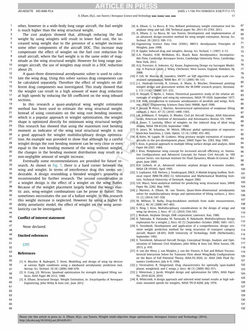
References
[1] A. Büscher, R. Radespiel, T. Streit, Modelling and design of wing tip devices at various flight conditions using a databased aerodynamic prediction tool, Aerosp. Sci. Technol. 10 (8) (2006) 668–678.
[2] A. Craig, J.D. McLean, Spanload optimization for strength designed lifting sur-faces, AlAA Paper 88-2512, 1988.
[3] A. Elham, Structural Design: Weight Estimation, in: Encyclopedia of Aerospace Engineering, John Wiley & Sons Ltd., June 2012.
[4] A. Elham, G. La Rocca, R. Vos, Refined preliminary weight estimation tool for airplane wing and tail, SAE Technical paper No. 2011-01-2765, 2011.
[5] A. Elham, G. La Rocca, M. van Tooren, Development and implementation of an advanced, design-sensitive method for wing weight estimation, Aerosp. Sci. Technol. 29 (2013) 100–113.
[6] Engineering Science Data Unit (ESDU), 98013, Aerodynamic Principles of Winglets, June 1998.
[7] R. Eppler, Induced drag and winglets, Aerosp. Sci. Technol. 1 (1997) 3–15.[8] G.A. Flandro, H.M. McMahon, R.L. Roach, Basic Aerodynamics: Incompress-
ible Flow, Cambridge Aerospace Series, Cambridge University Press, Cambridge, New York, 2012.
[9] A.I.J. Forrester, A. Sobester, A.J. Keane, Engineering Design via Surrogate Model-ing: A Practical Guide, J. Wiley, Chichester, West Sussex, England, Hoboken, NJ, 2008.
[10] P. Gill, W. Murray, M. Saunders, SNOPT: an SQP algorithm for large-scale con-strained optimization, SIAM Rev. 47 (1) (2005) 99–131.
[11] J.-L. Hantrais-Gervois, R. Grenon, A. Mann, A. Büscher, Downward pointing winglet design and assessment within the M-DAW research project, Aeronaut. J. 113 (1142) (2009) 221–232.
[12] H. Heyson, G. Riebe, C. Fulton, Theoretical parametric study of the relative ad-vantages of winglets and wing-tip extensions, NASA TP-1020, September 1977.
[13] D.R. Holt, Introduction to transonic aerodynamics of aerofoils and wings, Tech. rep., ESDU (Engineering Sciences Data Unit) 90008, April 1990.
[14] P. Jansen, R. Perez, J. Martins, Aerostructural optimization of nonplanar lifting surfaces, J. Aircr. 47 (5) (2010) 1490–1503.
[15] L.R. Jenkinson, P. Simpkin, D. Rhodes, Civil Jet Aircraft Design, AIAA Education Series, American Institute of Aeronautics and Astronautics, Reston, VA, 1999.
[16] R. Jones, T. Lasinsky, Effect of winglets on the induced drag of ideal wing shapes, NASA TM-81230, September 1980.
[17] D. Jones, M. Schonlau, W. Welch, Efficient global optimization of expensive black-box functions, J. Glob. Optim. 13 (4) (1998) 455–492.
[18] R. Kelm, M. Lapple, M. Grabietz, Wing primary weight estimation of transport aircrafts in the pre-development phase, SAWE Paper No. 2283, May 1995.
[19] I. Kroo, A general approach to multiple lifting surface design and analysis, AlAA Paper 84-2507, 1984.
[20] I. Kroo, Nonplannar wing concept for increased aircraft efficiency, in: Innova-tive Configurations and Advanced Concepts for Future Civil Aircraft, in: VKI Lecture Series, von Karman Institute for Fluid Dynamics, Rhode-St-Genese, Bel-gium, June 2005.
[21] R.H. Liebeck, et al., Advanced subsonic airplane design & economic studies, NASA CR-195443, April 1995.
[22] S. Lophaven, H.B. Nielsen, J. Sondergaard, DACE, A Matlab kriging toolbox, Tech-nical report IMM-TR-2002-12, Information and Mathematical Modeling Insti-tute, Technical University of Denmark, August 2002.
[23] S.H. Macci, Semi-analytical method for predicting wing structural mass, SAWE Paper No. 2282, May 1995.
[24] J. Mariens, A. Elham, M. van Tooren, Quasi-three-dimensional aerodynamic solver for multidisciplinary design and optimization of lifting surfaces, J. Aircr. 51 (2) (2014) 547–558.
[25] M. Méheut, D. Bailly, Drag-breakdown methods from wake measurements, AIAA J. 46 (4) (2008) 847–862.
[26] S. Ning, I. Kroo, Multidisciplinary considerations in the design of wings and wing tip devices, J. Aircr. 47 (2) (2010) 534–543.
[27] J. Roskam, Airplane Design, DAR corporation, Lawrence, Kan, 1986.[28] K. Takenaka, K. Hatanaka, W. Yamazaki, K. Nakahashi, Multidisciplinary design
exploration for a winglet, J. Aircr. 45 (5) (September–October 2008) 1601–1611.[29] E. Torenbeek, Development and application of a comprehensive, design sen-
sitive weight prediction method for wing structures of transport category aircraft, Report LR-693, Delft University of Technology, Delft (Netherlands), September 1992.
[30] E. Torenbeek, Advanced Aircraft Design, Conceptual Design, Analysis and Opti-mization of Subsonic Civil Airplanes, John Wiley & Sons Ltd, West Sussex, UK, 2013, p. 410.
[31] A. van der Wees, J. van Muijden, J. van der Vooren, A Fast and Robust Viscous-Inviscid Interaction Solver for Transonic Flow about Wing/Body Configurations on the Basis of Full Potential Theory, AIAA-93-3026, in: AIAA 24th Fluid Dy-namics Conference, July 6–9, 1996.
[32] J. Verstraeten, R. Slingerland, Drag characteristics for optimally span-loaded planar, wingletted, and C wings, J. Aircr. 46 (3) (2009) 962–971.
[33] J. Weierman, J. Jacob, Winglet design and optimization for UAVs, AIAA Paper No. 2010-4224, 2010.
[34] R. Whitcomb, A design approach and selected wind tunnel results at high sub-sonic mounted speeds for winglets, NASA TN-D-8260, July 1976.
128
129
130
131
132