Embed Size (px)
Citation preview
MANUAL NO. SIEP C730600 43B
Technical ManualDeviceNetType SI-N3
YASKAWA AC Drive1000-Series Option
To properly use the product, read this manual thoroughly and retain for easy reference, inspection, and maintenance. Ensure the end user receives this manual.
2 YASKAWA ELECTRIC SIEP C730600 43B 1000-Series Option SI-N3 Technical Manual
Copyright © 2008 YASKAWA ELECTRIC CORPORATIONAll rights reserved. No part of this publication may be reproduced, stored in a retrieval system, or transmitted, in any form or by any means, mechanical, electronic, photocopying, recording, or otherwise, without the prior written permission of Yaskawa. No patent liability is assumed with respect to the use of the information contained herein. Moreover, because Yaskawa is constantly striving to improve its high-quality products, the information contained in this manual is subject to change without notice. Every precaution has been taken in the preparation of this manual. Yaskawa assumes no responsibility for errors or omissions. Neither is any liability assumed for damages resulting from the use of the information contained in this publication.
YASKAWA ELECTRIC SIEP C730600 43B 1000-Series Option SI-N3 Technical Manual 3
Table of Contents
1 PREFACE AND SAFETY . . . . . . . . . . . . . . . . . . . . . . . . . . . . . . . . . . . . . . . . . . . . . . . . 42 PRODUCT OVERVIEW. . . . . . . . . . . . . . . . . . . . . . . . . . . . . . . . . . . . . . . . . . . . . . . . . . 73 RECEIVING . . . . . . . . . . . . . . . . . . . . . . . . . . . . . . . . . . . . . . . . . . . . . . . . . . . . . . . . . . . 84 OPTION COMPONENTS . . . . . . . . . . . . . . . . . . . . . . . . . . . . . . . . . . . . . . . . . . . . . . . . 95 INSTALLATION PROCEDURE . . . . . . . . . . . . . . . . . . . . . . . . . . . . . . . . . . . . . . . . . . 116 RELATED PARAMETERS . . . . . . . . . . . . . . . . . . . . . . . . . . . . . . . . . . . . . . . . . . . . . . 197 CONFIGURING DEVICENET MESSAGING. . . . . . . . . . . . . . . . . . . . . . . . . . . . . . . . . 218 OUTPUT ASSEMBLIES (DRIVE CONSUMES) . . . . . . . . . . . . . . . . . . . . . . . . . . . . . . 239 INPUT ASSEMBLIES (DRIVE PRODUCES) . . . . . . . . . . . . . . . . . . . . . . . . . . . . . . . . 4010 GENERAL CLASS OBJECTS . . . . . . . . . . . . . . . . . . . . . . . . . . . . . . . . . . . . . . . . . . 6111 VENDOR-SPECIFIC (YASKAWA) CLASS OBJECTS. . . . . . . . . . . . . . . . . . . . . . . . 7112 TROUBLESHOOTING . . . . . . . . . . . . . . . . . . . . . . . . . . . . . . . . . . . . . . . . . . . . . . . . 7313 TRUNK LINE AND DROP LINE LENGTH . . . . . . . . . . . . . . . . . . . . . . . . . . . . . . . . . 7814 SPECIFICATIONS. . . . . . . . . . . . . . . . . . . . . . . . . . . . . . . . . . . . . . . . . . . . . . . . . . . . 79

4 YASKAWA ELECTRIC SIEP C730600 43B 1000-Series Option SI-N3 Technical Manual
1 Preface and Safety
1 Preface and SafetyYaskawa manufactures products used as components in a wide variety of industrial systems and equipment. The selection and application of Yaskawa products remain the responsibility of the equipment manufacturer or end user. Yaskawa accepts no responsibility for the way its products are incorporated into the final system design. Under no circumstances should any Yaskawa product be incorporated into any product or design as the exclusive or sole safety control. Without exception, all controls should be designed to detect faults dynamically and fail safely under all circumstances. All systems or equipment designed to incorporate a product manufactured by Yaskawa must be supplied to the end user with appropriate warnings and instructions as to the safe use and operation of that part. Any warnings provided by Yaskawa must be promptly provided to the end user. Yaskawa offers an express warranty only as to the quality of its products in conforming to standards and specifications published in the Yaskawa manual. NO OTHER WARRANTY, EXPRESS OR IMPLIED, IS OFFERED. Yaskawa assumes no liability for any personal injury, property damage, losses, or claims arising from misapplication of its products.
Applicable DocumentationThe following manuals are available for the option:
Terms and Abbreviations
DeviceNet SI-N3 Option
Yaskawa AC Drive 1000-Series Option DeviceNet Installation ManualManual No: TOBPC73060043
Read this manual first.The installation manual is packaged with the option and contains information required to install the option and set up related drive parameters.
Yaskawa AC Drive 1000-Series Option DeviceNet Technical ManualManual No: SIEPC73060043
The technical manual contains detailed information about the option. Access the following sites to obtain the technical manual:U.S.: http://www.yaskawa.comEurope: http://www.yaskawa.eu.comJapan: http://www.e-mechatronics.comFor questions, contact your local Yaskawa sales office or the nearest Yaskawa representative.
Yaskawa DriveYaskawa AC Drive 1000-SeriesQuick Start Guide
The drive manuals cover basic installation, wiring, operation procedures, functions, troubleshooting, and maintenance information.The manuals also include important information about parameter settings and drive tuning.Access these sites to obtain Yaskawa instruction manuals:U.S.: http://www.yaskawa.comEurope: http://www.yaskawa.eu.comJapan: http://www.e-mechatronics.comFor questions, contact your local Yaskawa sales office or the nearest Yaskawa representative.
Yaskawa AC Drive 1000-Series Technical Manual
Note: Indicates supplemental information that is not related to safety messages.Drive: Yaskawa AC Drive 1000-SeriesOption: Yaskawa AC Drive 1000-Series SI-N3 DeviceNet Option V/f: V/f ControlV/f w/PG: V/f Control with PGOLV: Open Loop Vector Control CLV: Closed Loop Vector Control OLV/PM: Open Loop Vector Control for PMAOLV/PM: Advanced Open Loop Vector Control for PMCLV/PM: Closed Loop Vector Control for PM

1 Preface and Safety
YASKAWA ELECTRIC SIEP C730600 43B 1000-Series Option SI-N3 Technical Manual 5
Registered Trademarks• DeviceNet is a trademark of the ODVA.• Trademarks are the property of their respective owners.
Supplemental Safety InformationRead and understand this manual before installing, operating, or servicing this option. Install the option according to this manual and local codes.
The following conventions indicate safety messages in this manual. Failure to heed these messages could cause fatal injury or damage products and related equipment and systems.
General Safety
DANGER Indicates a hazardous situation, which, if not avoided, will result in death or serious injury.
W ARNING Indicates a hazardous situation, which, if not avoided, could result in death or serious injury.
CAUTION Indicates a hazardous situation, which, if not avoided, could result in minor or moderate injury.
NOTICE
Indicates an equipment damage message.
General Precautions• The diagrams in this book may include options and drives without covers or safety shields to illustrate details. Be sure to reinstall
covers or shields before operating any devices. Use the option according to the instructions described in this manual.• Any illustrations, photographs, or examples used in this manual are provided as examples only and may not apply to all products
to which this manual is applicable.• The products and specifications described in this manual or the content and presentation of the manual may be changed without
notice to improve the product and/or the manual.• When ordering new copies of the manual, contact a Yaskawa representative or the nearest Yaskawa sales office and provide the
manual number shown on the front cover.
DANGER Heed the safety messages in this manual.Failure to comply will result in death or serious injury.The operating company is responsible for any injuries or equipment damage resulting from failure to heed the warnings in this manual.

1 Preface and Safety
6 YASKAWA ELECTRIC SIEP C730600 43B 1000-Series Option SI-N3 Technical Manual
NOTICE
Do not modify the drive or option circuitry.Failure to comply could result in damage to the drive or option and will void warranty. Yaskawa is not responsible for any modification of the product made by the user. This product must not be modified.Do not expose the drive or option to halogen group disinfectants.Failure to comply may cause damage to the electrical components in the drive or option. Do not pack the drive in wooden materials that have been fumigated or sterilized.Do not sterilize the entire package after the product is packed.

2 Product Overview
YASKAWA ELECTRIC SIEP C730600 43B 1000-Series Option SI-N3 Technical Manual 7
2 Product Overview
About This ProductThe SI-N3 Option provides a communications connection between the drive and an ODVA DeviceNet network. The SI-N3 Option connects the drive to a DeviceNet network and facilitates the exchange of data.
DeviceNet is a communications link that connects industrial devices (e.g., limit switches, photoelectric switches, valve manifolds, motor starters, smart motor controllers, operator interfaces, and variable frequency drives) and control devices (e.g., programmable controllers and computers) to a network. DeviceNet is a simple networking solution that reduces the cost and time to wire and install factory automation devices while providing interchangeability of similar components from multiple vendors.
Installing the option to a drive allows a DeviceNet master device to:
• operate the drive• monitor the operation status of the drive• change parameter settings.
Figure 1
Figure 1 DeviceNet Approved
Applicable ModelsThe option can be used with the models in Table 1.
Table 1 Applicable Models
Drive Series Drive Model NumberA1000 All models
8 YASKAWA ELECTRIC SIEP C730600 43B 1000-Series Option SI-N3 Technical Manual
3 Receiving
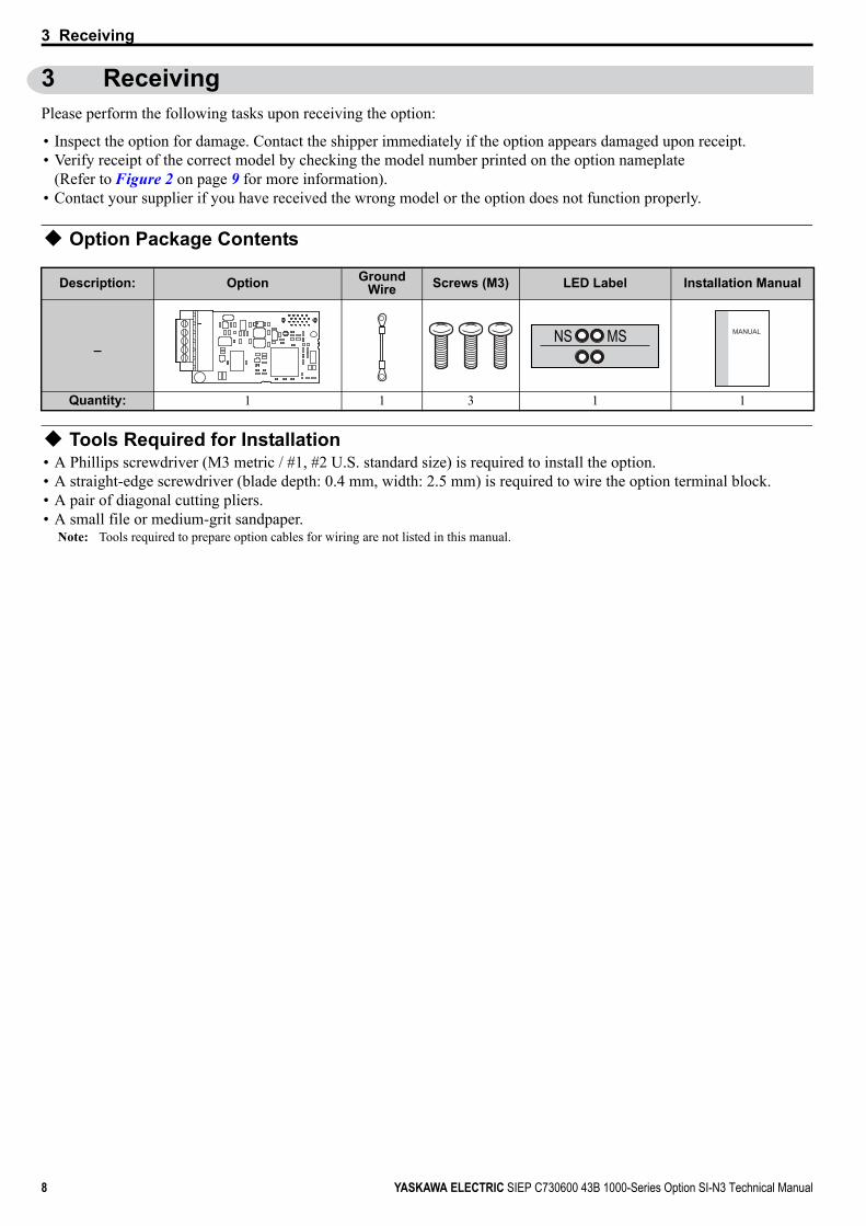
3 ReceivingPlease perform the following tasks upon receiving the option:
• Inspect the option for damage. Contact the shipper immediately if the option appears damaged upon receipt.• Verify receipt of the correct model by checking the model number printed on the option nameplate
(Refer to Figure 2 on page 9 for more information).• Contact your supplier if you have received the wrong model or the option does not function properly.
Option Package Contents
Tools Required for Installation• A Phillips screwdriver (M3 metric / #1, #2 U.S. standard size) is required to install the option.• A straight-edge screwdriver (blade depth: 0.4 mm, width: 2.5 mm) is required to wire the option terminal block.• A pair of diagonal cutting pliers.• A small file or medium-grit sandpaper.
Note: Tools required to prepare option cables for wiring are not listed in this manual.
Description: Option Ground Wire Screws (M3) LED Label Installation Manual
_
Quantity: 1 1 3 1 1
NS MS MANUAL

4 Option Components
YASKAWA ELECTRIC SIEP C730600 43B 1000-Series Option SI-N3 Technical Manual 9
4 Option Components
DeviceNet OptionFigure 2
Figure 2 DeviceNet Option Components
Terminal Block CN1The communication terminal is a pluggable terminal block that serves as the connection point of the DeviceNet network communication cable to the option.
Table 2 Terminal Descriptions
A – Terminal block CN1 E – LED (MS) <1>
B – Model number F – LED (NS) <1>
C – Connector (CN5) G – Ground terminal and installation hole <2>
<1> Refer to Option LED Display on page 10 for details on the LEDs.<2> The ground wire provided in the option shipping package must be connected during installation.
D – Installation hole
Terminal Pin Color Signal Description1 Black V- Network common
2 Blue CAN_L CAN data Low
3 – Shield Cable shield
4 White CAN_H CAN data High
5 Red V+ Communications network power DC +24V
Underside
CA B
D
E
FG
SI-N3
4 Option Components
10 YASKAWA ELECTRIC SIEP C730600 43B 1000-Series Option SI-N3 Technical Manual
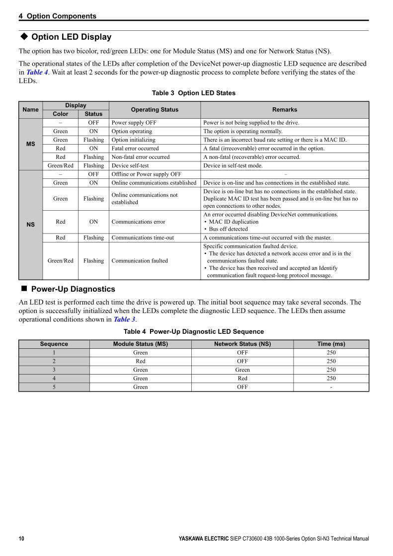
Option LED DisplayThe option has two bicolor, red/green LEDs: one for Module Status (MS) and one for Network Status (NS).
The operational states of the LEDs after completion of the DeviceNet power-up diagnostic LED sequence are described in Table 4. Wait at least 2 seconds for the power-up diagnostic process to complete before verifying the states of the LEDs.
Table 3 Option LED States
Power-Up DiagnosticsAn LED test is performed each time the drive is powered up. The initial boot sequence may take several seconds. The option is successfully initialized when the LEDs complete the diagnostic LED sequence. The LEDs then assume operational conditions shown in Table 3.
Table 4 Power-Up Diagnostic LED Sequence
NameDisplay
Operating Status RemarksColor Status
MS
– OFF Power supply OFF Power is not being supplied to the drive.Green ON Option operating The option is operating normally.Green Flashing Option initializing There is an incorrect baud rate setting or there is a MAC ID.Red ON Fatal error occurred A fatal (irrecoverable) error occurred in the option.Red Flashing Non-fatal error occurred A non-fatal (recoverable) error occurred.
Green/Red Flashing Device self-test Device in self-test mode.
NS
– OFF Offline or Power supply OFF –
Green ON Online communications established Device is on-line and has connections in the established state.
Green Flashing Online communications not established
Device is on-line but has no connections in the established state.Duplicate MAC ID test has been passed and is on-line but has no open connections to other nodes.
Red ON Communications error An error occurred disabling DeviceNet communications.• MAC ID duplication• Bus off detected
Red Flashing Communications time-out A communications time-out occurred with the master.
Green/Red Flashing Communication faulted
Specific communication faulted device.• The device has detected a network access error and is in the communications faulted state.
• The device has then received and accepted an Identify communication fault request-long protocol message.
Sequence Module Status (MS) Network Status (NS) Time (ms)1 Green OFF 2502 Red OFF 2503 Green Green 2504 Green Red 2505 Green OFF -

5 Installation Procedure
YASKAWA ELECTRIC SIEP C730600 43B 1000-Series Option SI-N3 Technical Manual 11
5 Installation Procedure
Section Safety
DANGER
Electrical Shock HazardDo not connect or disconnect wiring while the power is on.Failure to comply will result in death or serious injury.Disconnect all power to the drive and wait at least the amount of time specified on the drive front cover safety label. After all indicators are off, measure the DC bus voltage to confirm safe level, and check for unsafe voltages before servicing. The internal capacitor remains charged after the power supply is turned off.
W ARNING
Electrical Shock HazardDo not remove the front covers of the drive while the power is on.Failure to comply could result in death or serious injury.The diagrams in this section may include options and drives without covers or safety shields to show details. Be sure to reinstall covers or shields before operating any devices. Use the option according to the instructions described in this manual.
Do not allow unqualified personnel to use equipment.Failure to comply could result in death or serious injury.Maintenance, inspection, and replacement of parts must be performed only by authorized personnel familiar with installation, adjustment, and maintenance of this product.
Do not touch circuit boards while the power to the drive is on.Failure to comply could result in death or serious injury.
Do not use damaged wires, stress the wiring, or damage the wire insulation.Failure to comply could result in death or serious injury.
Fire HazardTighten all terminal screws to the specified tightening torque.Loose electrical connections could result in death or serious injury by fire due to overheating of electrical connections.
NOTICE
Damage to EquipmentObserve proper electrostatic discharge (ESD) procedures when handling the option, drive, and circuit boards.Failure to comply may result in ESD damage to circuitry.
Never shut the power off while the drive is running or outputting voltage.Failure to comply may cause the application to operate incorrectly or damage the drive.
Do not operate damaged equipment. Failure to comply may cause further damage to the equipment.Do not connect or operate any equipment with visible damage or missing parts.
Do not use unshielded cable for control wiring.Failure to comply may cause electrical interference resulting in poor system performance.Use shielded twisted-pair wires and ground the shield to the ground terminal of the drive.
5 Installation Procedure
12 YASKAWA ELECTRIC SIEP C730600 43B 1000-Series Option SI-N3 Technical Manual
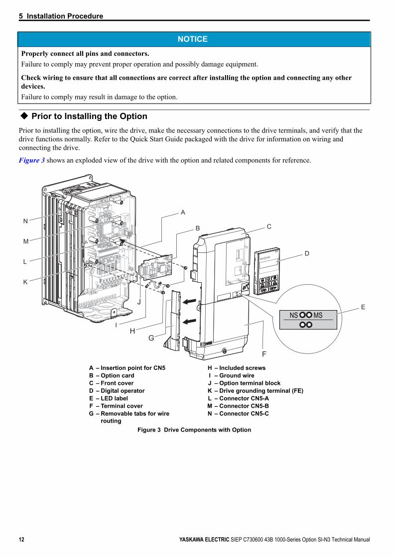
Prior to Installing the OptionPrior to installing the option, wire the drive, make the necessary connections to the drive terminals, and verify that the drive functions normally. Refer to the Quick Start Guide packaged with the drive for information on wiring and connecting the drive.
Figure 3 shows an exploded view of the drive with the option and related components for reference.Figure 3
Figure 3 Drive Components with Option
Properly connect all pins and connectors. Failure to comply may prevent proper operation and possibly damage equipment.
Check wiring to ensure that all connections are correct after installing the option and connecting any other devices. Failure to comply may result in damage to the option.
A – Insertion point for CN5 H – Included screwsB – Option card I – Ground wireC – Front cover J – Option terminal blockD – Digital operator K – Drive grounding terminal (FE)E – LED label L – Connector CN5-AF – Terminal cover M – Connector CN5-BG – Removable tabs for wire
routingN – Connector CN5-C
NOTICE
NS MS
F
H
K
L
M
N
I
B C
D
E
A
G
J

5 Installation Procedure
YASKAWA ELECTRIC SIEP C730600 43B 1000-Series Option SI-N3 Technical Manual 13
Installing the OptionRefer to the instructions below to install the option.
1. Shut off power to the drive, wait the appropriate amount of time for voltage to dissipate, then remove the digital operator (D) and front covers (C, F). Refer to the Quick Start Guide packaged with the drive for directions on removing the front covers. Cover removal varies depending on drive size.
DANGER! Electrical Shock Hazard. Disconnect all power to the drive and wait at least the amount of time specified on the drive front cover safety label. After all indicators are off, measure the DC bus voltage to confirm safe level, and check for unsafe voltages before servicing to prevent electric shock. The internal capacitor remains charged even after the power supply is turned off.
NOTICE: Damage to Equipment. Observe proper electrostatic discharge procedures (ESD) when handling the option, drive, and circuit boards. Failure to comply may result in ESD damage to circuitry.Figure 4
Figure 4 Remove the Front Covers and Digital Operator
2. With the front covers and digital operator removed, apply the LED label (E) in the appropriate position on the drive top front cover (C).
Figure 5
Figure 5 Apply the LED Label
C
D
F
NS MS
C
E
5 Installation Procedure
14 YASKAWA ELECTRIC SIEP C730600 43B 1000-Series Option SI-N3 Technical Manual
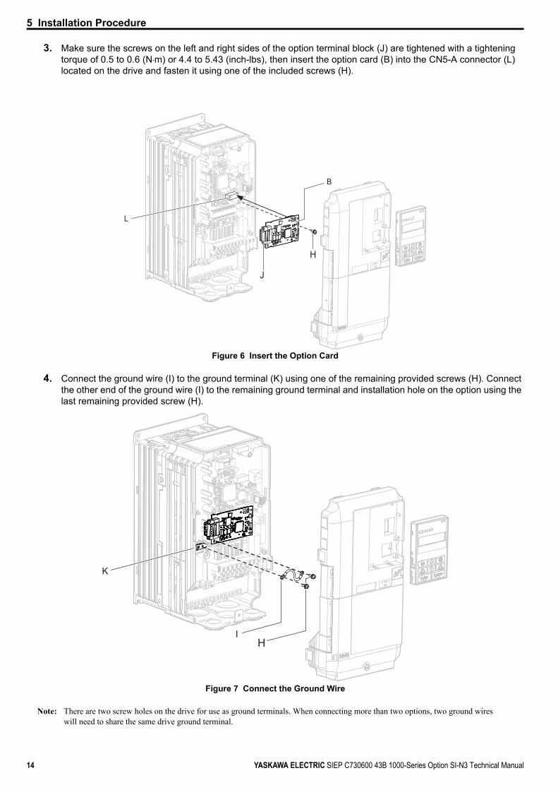
3. Make sure the screws on the left and right sides of the option terminal block (J) are tightened with a tightening torque of 0.5 to 0.6 (N m) or 4.4 to 5.43 (inch-lbs), then insert the option card (B) into the CN5-A connector (L) located on the drive and fasten it using one of the included screws (H).
Figure 6
Figure 6 Insert the Option Card
4. Connect the ground wire (I) to the ground terminal (K) using one of the remaining provided screws (H). Connect the other end of the ground wire (I) to the remaining ground terminal and installation hole on the option using the last remaining provided screw (H).
Figure 7
Figure 7 Connect the Ground Wire
Note: There are two screw holes on the drive for use as ground terminals. When connecting more than two options, two ground wires will need to share the same drive ground terminal.
NS MS
L
H
B
J
HI
K

5 Installation Procedure
YASKAWA ELECTRIC SIEP C730600 43B 1000-Series Option SI-N3 Technical Manual 15
5. Select the proper type and length of communication cables and drop line.Refer to the ODVA website (www.odva.org) for more information on network cabling.Refer to Trunk Line and Drop Line Length on page 78 for details on selecting trunk line and drop line lengths. Only connect network termination resistors (121 Ω, ±1%, 1/4 W) to nodes of the two ends of trunk line. Refer to ODVA specifications for more details on DeviceNet termination.
6. Prepare and connect the communication cables to the terminal block as shown in Figure 8 and Figure 9. Take particular precaution to ensure that each wire is properly connected and wire insulation is not accidentally pinched into electrical terminals.
WARNING! Fire Hazard. Tighten all terminal screws according to the specified tightening torque. Loose electrical connections could result in death or serious injury by fire due to overheating electrical connections. Tightening screws beyond the specified tightening torque may result in erroneous operation, damage to the terminal block, or cause a fire.
NOTICE: Heat shrink tubing or electrical tape may be required to ensure that cable shielding does not come into contact with other wiring. Insufficient insulation may cause a short circuit that can damage the option or the drive.Figure 8
Figure 8 Preparing Ends of Shielded CableNote: Separate communication cables from main circuit wiring and other electrical lines.
Figure 9
Figure 9 Preparing and Connecting Communication Cable Wiring
Insulation
Shield sheath
Option terminal DeviceNet Master
ShieldShield
(Insulate with electrical tape or shrink tubing)
Preparing wire ends: Screwdriver blade size
about 5.5 mm (7/32”)When not usingcrimped insulatedsleeves
Pull back the shielding and lightly twist the end with fingers, keeping the ends from fraying.
DeviceNet drop line(do not solder ends)
Blade depth of 0.4 mm or less
Blade width of 2.5 mm or less
Tightening torque:0.5 to 0.6 N mor 4.4 to 5.3 in-lbs
Terminal block CN1
Loosen the screws and insert the wire into the opening on the terminal block.

5 Installation Procedure
16 YASKAWA ELECTRIC SIEP C730600 43B 1000-Series Option SI-N3 Technical Manual
Connection DiagramFigure 10
Figure 10 Option Connection Diagram
<1> The ground wire provided in the option shipping package must be connected during installation.
7. Route the option wiring.Depending on the drive model, some drives may require routing wire through the side of the front cover to the outside. In these cases, cut out the perforated openings in the left side of the drive front cover as shown in Figure 11-A, and leave no sharp edges to damage wiring.
Route the wiring inside the enclosure as show in Figure 11-B for drives that do not require routing through the front cover. Refer to the Peripheral Devices & Options section of the drive Technical Manual for more information.
Figure 11
Figure 11 Wire Routing Examples
8. After wiring the terminal block, recheck the option wire routing performed in step 7.
A – Route wires through the openings provided on the left side of the front cover. <1>
<1> The drive will not meet NEMA Type 1 requirements if wiring is exposed outside the enclosure.
B – Use the open space provided inside the drive to route option wiring.
Drive
SI-N3
MUVW
R
V+V-CAN_HCAN_L
Shield
ST
CN5-AFE
<1>
DeviceNet Masteror
drop line
DeviceNet Cable
MotorPower
(Red)(Black)(White)(Blue)
BA

5 Installation Procedure
YASKAWA ELECTRIC SIEP C730600 43B 1000-Series Option SI-N3 Technical Manual 17
9. Replace and secure the front covers of the drive (C, F) and replace the digital operator (D).Figure 12
Figure 12 Replace the Front Covers and Digital OperatorNote: Take proper precautions when wiring the option so that the front covers will easily fit back onto the drive. Make sure no cables
are pinched between the front covers and the drive when replacing the covers.
10. Set drive parameters in Table 6 for proper option performance.
Option MAC ID
Parameter F6-50, MAC ID Setting 0 to 64The option MAC ID is set with drive parameter F6-50. MAC ID settings between 0~63 are considered valid MAC IDs; setting 64 indicates a network-settable MAC ID.
The option reads the MAC ID value from F6-50 upon power-up and upon a network reset.
F
C
D
5 Installation Procedure
18 YASKAWA ELECTRIC SIEP C730600 43B 1000-Series Option SI-N3 Technical Manual
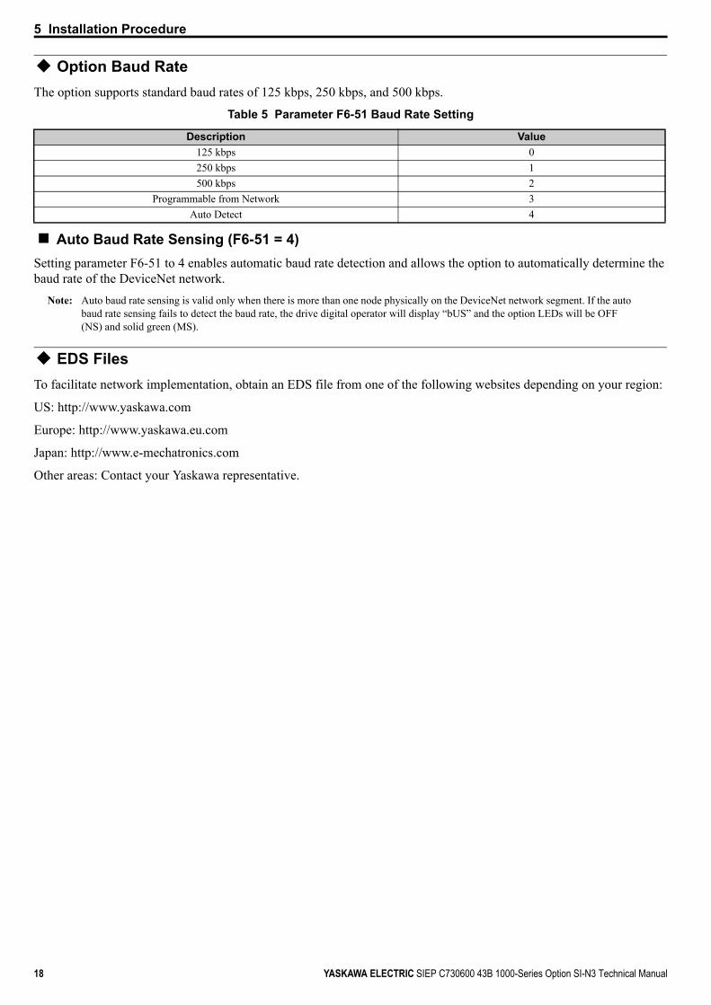
Option Baud RateThe option supports standard baud rates of 125 kbps, 250 kbps, and 500 kbps.
Table 5 Parameter F6-51 Baud Rate Setting
Auto Baud Rate Sensing (F6-51 = 4)Setting parameter F6-51 to 4 enables automatic baud rate detection and allows the option to automatically determine the baud rate of the DeviceNet network.
Note: Auto baud rate sensing is valid only when there is more than one node physically on the DeviceNet network segment. If the auto baud rate sensing fails to detect the baud rate, the drive digital operator will display “bUS” and the option LEDs will be OFF (NS) and solid green (MS).
EDS FilesTo facilitate network implementation, obtain an EDS file from one of the following websites depending on your region:
US: http://www.yaskawa.com
Europe: http://www.yaskawa.eu.com
Japan: http://www.e-mechatronics.com
Other areas: Contact your Yaskawa representative.
Description Value125 kbps 0250 kbps 1500 kbps 2
Programmable from Network 3Auto Detect 4

6 Related Parameters
YASKAWA ELECTRIC SIEP C730600 43B 1000-Series Option SI-N3 Technical Manual 19
6 Related ParametersThe following parameters are used to set up the drive for operation with the option.
Confirm proper setting of the all parameters in Table 6 before starting network communications.
Table 6 Related Parameters
No. (Addr. Hex)
Name Description Values
b1-01(180)
<1>
Frequency Reference Selection 1
Selects the frequency reference input source0: Digital Operator - Digital preset speed d1-01 to d1-171: Terminals - Analog input terminal A1 or A22: MEMOBUS/Modbus communications 3: Option 4: Pulse Input (Terminal RP)
Default: 1Range: 0 to 4(Set to 3 for DeviceNet only)
b1-02(181)
<1>Run Command Selection 1
Selects the run command input source0: Digital Operator - RUN and STOP keys1: Digital input terminals S 2: MEMOBUS/Modbus communications 3: Option
Default: 1Range: 0 to 3(Set to 3 for DeviceNet only)
F6-01(3A2)
Communications Error Operation Selection
Determines drive response after a bUS error during communications with the option0: Ramp to Stop 1: Coast to Stop2: Fast-Stop3: Alarm Only <2>
Default: 1Range: 0 to 3
F6-02(3A3)
External Fault from Comm. Option Detection Selection
Sets the condition for external fault detection (EF0)0: Always detected1: Detected only during operation
Default: 0Range: 0, 1
F6-03(3A4)
External Fault from Comm. Option Operation Selection
Determines drive response for external fault input (EF0) detection during DeviceNet communication0: Ramp to Stop 1: Coast to Stop2: Fast-Stop3: Alarm Only <2>
Default: 1Range: 0 to 3
F6-06(3A7)
<3>
Torque Reference/Torque Limit Selection from Comm. Option
0: Torque reference / torque limit via network communications are disabled.1: Torque reference / torque limit via network communications are enabled. <4>
Default: 0Range: 0, 1
F6-07(3A8)
Multi-Step Speed Enable/Disable Selection when NefRef/ComRef is Selected
0: Multi-step speed reference disabled (F7 functionality)1: Multi-step speed reference allowed (V7 functionality)
Default: 0Range: 0, 1
F6-08(36A)
Reset Communication Parameters
Determines which F6- and F7- parameters are reset to default values when initializing the drive using A1-03.0: Do not reset parameters1: Reset parameters
Default: 0Range: 0, 1
F6-50(3C1)
<5> <7>DeviceNet MAC ID Selects the drive MAC address
Note: Used in the DeviceNet Object
Default: 64Min: 0Max: 64
F6-51(3C2)
<7>
DeviceNet Communication Speed
DeviceNet communication speed0: 125 kbps1: 250 kbps2: 500 kbps3: Programmable from network4: Auto detectNote: Used in the DeviceNet Object
Default: 4Range: 0 to 4
F6-52(3C3)
<6>DeviceNet PCA Setting I/O Polled Consuming Assembly data instance
Note: Used in the Connection Object
Default: 21Min: 0Max: 255
F6-53(3C4)
<6>DeviceNet PPA Setting I/O Polled Producing Assembly data instance
Note: Used in the Connection Object
Default: 71Min: 0Max: 255
F6-54(3C5)
<7>
DeviceNet Idle Mode Fault Detection
When enabled, detecting idle messages causes the option to set Run and Freq to 0.0: Detection enabled1: No detection
Default: 0Range: 0, 1

6 Related Parameters
20 YASKAWA ELECTRIC SIEP C730600 43B 1000-Series Option SI-N3 Technical Manual
F6-55(3C6)
DeviceNet Baud Rate Monitor
(Read only) DeviceNet actual communication speed0: 125 kbps1: 250 kbps2: 500 kbpsNote: Used in the DeviceNet Object
Default: 0Range: 0 to 2
F6-56(3D7) DeviceNet Speed Scaling Sets the scaling factor for the Speed Monitor in the DeviceNet Object Class 2A hex
Note: Used in the AC/DC Drive Object
Default: 0Min: -15Max: 15
F6-57(3D8) DeviceNet Current Scaling
Sets the scaling factor for the Output Current Monitor in the DeviceNet Object Class 2A hexNote: Used in the AC/DC Drive Object
Default: 0Min: -15Max: 15
F6-58(3D9) DeviceNet Torque Scaling Sets the scaling factor for the Torque Monitor in the DeviceNet Object Class 2A hex
Note: Used in the AC/DC Drive Object
Default: 0Min: -15Max: 15
F6-59(3DA) DeviceNet Power Scaling Sets the scaling factor for the Power Monitor in the DeviceNet Object Class 2A hex
Note: Used in the AC/DC Drive Object
Default: 0Min: -15Max: 15
F6-60(3DB) DeviceNet Voltage Scaling Sets the scaling factor for the Voltage Monitor in the DeviceNet Object Class 2A
Note: Used in the AC/DC Drive Object
Default: 0Min: -15Max: 15
F6-61(3DC) DeviceNet Time Scaling Sets the scaling factor for the Time Monitor in the DeviceNet Object Class 2A hex
Note: Used in the AC/DC Drive Object
Default: 0Min: -15Max: 15
F6-62(3DD)
DeviceNet Heartbeat Interval
Sets the heartbeat intervalNote: Used in the Identity Object
Default: 0Min: 0Max: 10
F6-63(3DE)
DeviceNet Network MAC ID
(Read only) Actual MAC addressNote: Used in the DeviceNet Object
Default: 0Min: 0Max: 63
U6-98(7F8) Previous Option Fault
Displays previous faulted status.0: No fault1: Option failure2: PLC in idle state3: Force fault1000: Network power loss1001: Connection timeout1002: Duplicate MAC ID1003: Bus-offNote: Used in DeviceNet Option Faults
Range: 0 to 3; 1000 to 1003
U6-99(7F9) Current Option Fault
Displays the most recent fault status.0:No fault1: Option failure2: PLC in idle state3: Force fault1000: Network power loss1001: Connection timeout1002: Duplicate MAC ID1003: Bus-offNote: Used in DeviceNet Option Faults
Range: 0 to 3; 1000 to 1003
<1> To start and stop the drive with the DeviceNet master device using serial communications, set b1-02 to 3 or set the Net Control bit in the assemblies or Control Supervisor Object. To control the frequency reference of the drive via the master device, set b1-01 to 3 or set the Net Reference bit in the assemblies or AC/DC object.
<2> Setting F6-01 or F6-03 to 3 will allow the drive to continue to operate after detecting a fault. When allowing the drive to continue operation after fault detection, be sure to take proper safety measures such as installing an emergency stop switch.
<3> Enabled in CLV, AOLV/PM, and CLV/PM control modes (A1-02 = 3, 6, or 7). When enabled, d5-01 determines whether the value is read as the torque limit value (d5-01 = 0) or read as the torque reference value (d5-01 = 1). This value is read as the torque limit in CLV/PM.
<4> Default setting specifies that the torque reference or torque limit is to be provided via network communications (F6-06 = 1). The motor may not rotate if no torque reference or torque limit is supplied from the PLC.
<5> All MAC addresses must be unique.<6> Setting unavailable values will initialize Polled Consuming Assembly (PCA) and Polled Producing Assembly (PPA).<7> Cycle power for setting changes to take effect.
No. (Addr. Hex)
Name Description Values

7 Configuring DeviceNet Messaging
YASKAWA ELECTRIC SIEP C730600 43B 1000-Series Option SI-N3 Technical Manual 21
7 Configuring DeviceNet MessagingThis section provides information on the methods used to control the drive on DeviceNet.
Drive Configuration on DeviceNet
Polled ConfigurationConfigure the drive DeviceNet polled connection before receiving commands from a master device. The two parameters that must be configured are:
• F6-52: Polled Consuming Assembly (PCA) Note: Output assembly consumed by the drive.
• F6-53: Polled Producing Assembly (PPA) Note: Input assembly produced by the drive.
The default connection paths for the option are set for Extended Speed Control.
The PCA and PPA parameters can be accessed by two methods:
• A software configuration tool (not supplied), and Yaskawa Electronic Data Sheet (EDS) Note: The PCA and PPA parameters can be accessed from the “DN: Polled Config” parameter group.
• A software configuration tool (not supplied), via a DeviceNet message path, such as Extended Speed ControlNote: Use DeviceNet Connection Object to change the PCA or PPA if required by the application (Class 5, Instance 1, Attributes 14
and 16)
One of each PCA and PPA assembly from the following table must be selected to configure the drive for polled operation.
Table 7 Supported Polled Assemblies (PCA and PPA)
Assembly Number
(decimal)Description Type Bytes Page
20 Basic Speed Control Output - 20 (0x14) PCA 4 2321 Extended Speed Control Output - 21 (0x15) (Default Setting) PCA 4 2322 Speed and Torque Control Output - 22 (0x16) PCA 6 2423 Extended Speed and Torque Control Output - 23 (0x17) PCA 6 2470 Basic Speed Control Input - 70 (0x46) PPA 4 4071 Extended Speed Control Input - 71 (0x47) (Default Setting) PPA 4 4072 Speed and Torque Control Input - 72 (0x48) PPA 6 4173 Extended Speed and Torque Control Input - 73 (0x49) PPA 6 42
100 MEMOBUS/Modbus Message Command (Vendor Specific Yaskawa Electric (YE) Assy) - 100 (0x64) PCA 5 25
101 Standard Control (Vendor Specific Yaskawa Electric (YE) Assy) - 101 (0x65) PCA 8 26102 Accel/Decel Time (Vendor Specific Yaskawa Electric (YE) Assy) - 102 (0x66) PCA 8 27105 Enhanced Speed Control, Dynamic (Vendor Specific Yaskawa Electric (YE) Assy) - 105 (0x69) PCA 8 28106 Enhanced Control (Vendor Specific Yaskawa Electric (YE) Assy) - 106 (0x6A) PCA 8 30107 Standard DI/DO Control (Vendor Specific Yaskawa Electric (YE) Assy) - 107 (0x6B) PCA 8 31108 Enhanced Torque Control, Dynamic (Vendor Specific Yaskawa Electric (YE) Assy) - 108 (0x6C) PCA 8 32120 Speed Command 1 (Vendor Specific Yaskawa Electric (YE) Assy) - 120 (0x78) PCA 4 33121 Torque Command 1 (Vendor Specific Yaskawa Electric (YE) Assy) - 121 (0x79) PCA 4 34122 Speed Command 2 (Vendor Specific Yaskawa Electric (YE) Assy) - 122 (0x7A) PCA 6 35123 Torque Command 2 (Vendor Specific Yaskawa Electric (YE) Assy) - 123 (0x7B) PCA 6 36124 Speed Dynamic Assy (Vendor Specific Yaskawa Electric (YE) Assy) - 124 (0x7C) PCA 8 37125 Torque Dynamic Assy (Vendor Specific Yaskawa Electric (YE) Assy) - 125 (0x7D) PCA 8 38126 Speed/Torque Assy (Vendor Specific Yaskawa Electric (YE) Assy) - 126 (0x7E) PCA 8 39130 Speed Status (Vendor Specific Yaskawa Electric (YE) Assy) - 130 (0x82) PPA 4 43131 Current Status (Vendor Specific Yaskawa Electric (YE) Assy) - 131 (0x83) PPA 4 44132 Current & Speed Status (Vendor Specific Yaskawa Electric (YE) Assy) - 132 (0x84) PPA 6 45

7 Configuring DeviceNet Messaging
22 YASKAWA ELECTRIC SIEP C730600 43B 1000-Series Option SI-N3 Technical Manual
Additional Support for Setting Connection Path TypesThe option also supports symbolic encoding to support application tools and development tools that do not handle explicit message fragmentation. Symbolic encoding requires only a 3-byte long message where logical encoding requires 11 bytes.
The option has a third method of setting polled consumed and produced connection paths. Class 5, Instance 2, Attributes (100, 101) allow setting connection path with a single byte. For instance, to set the consumed connection path to 100, write 100 (0x64) to Attribute 101. See appendix C of “The CIP Networks Library, Volume 1" for more information on CIP segments
134 Speed Status Dynamic Assy (Vendor Specific Yaskawa Electric (YE) Assy) - 134 (0x86) PPA 8 46135 Current Status Dynamic Assy (Vendor Specific Yaskawa Electric (YE) Assy) - 135 (0x87) PPA 8 47136 Torque and Speed Status (Vendor Specific Yaskawa Electric (YE) Assy) - 136 (0x88) PPA 8 48150 MEMOBUS/Modbus Message Reply (Vendor Specific Yaskawa Electric (YE) Assy) - 150 (0x96) PPA 5 49151 Standard Status 1 (Vendor Specific Yaskawa Electric (YE) Assy) - 151 (0x97) PPA 8 50152 Standard Status 2 (Vendor Specific Yaskawa Electric (YE) Assy) -152 (0x98) PPA 8 51155 Enhanced Speed Status, Dynamic (Vendor Specific Yaskawa Electric (YE) Assy) - 155 (0x9B) PPA 8 53156 Enhanced Control Status (Vendor Specific Yaskawa Electric (YE) Assy) -156 (0x9C) PPA 8 54157 Standard DI/DO Status (Vendor Specific Yaskawa Electric (YE) Assy) - 157 (0x9D) PPA 8 56158 Enhanced Torque Status, Dynamic (Vendor Specific Yaskawa Electric (YE) Assy) - 158 (0x9E) PPA 8 57199 Change of State Response (Vendor Specific Yaskawa Electric (YE) Assy) - 199 (0xC7) PPA 8 59
Assembly Number
(decimal)Description Type Bytes Page

8 Output Assemblies (Drive Consumes)
YASKAWA ELECTRIC SIEP C730600 43B 1000-Series Option SI-N3 Technical Manual 23
8 Output Assemblies (Drive Consumes)The convention in this manual is from the PLC perspective. As such, an assembly is called an “Output Assembly” when outputted from the PLC and received by this node. An “Input Assembly” is outputted from this node and read by the PLC. This section details “Output Assemblies” that are “Consumed” by the drive.
Basic Speed Control Output - 20 (0x14)
Extended Speed Control Output - 21 (0x15)
Output Instance Byte Bit 7 Bit 6 Bit 5 Bit 4 Bit 3 Bit 2 Bit 1 Bit 0
20
0 – – – – – FaultReset – Run
Fwd1 -2 Speed Reference (Low Byte)3 Speed Reference (High Byte)
Name Description
Run FwdForward Run Command0: Stop1: Forward Run
Fault ResetFault Reset0: No Fault Reset1: Fault Reset
Speed Reference
Speed Command Sets drive speed referenceSpeed reference data:Frequency reference / 2SS (SS: Speed scale)Setting range: 0 to 0xFFFFFor example, when setting a reference of 1024 with a speed scale of 2Speed reference data = 1024 / 22 = 256 = 0x0100Unit depends on o1-03.
Output Instance Byte Bit 7 Bit 6 Bit 5 Bit 4 Bit 3 Bit 2 Bit 1 Bit 0
21
0 – NetRef
Net Ctrl – – Fault
ResetRunRev
Run Fwd
1 –2 Speed Reference (Low Byte)3 Speed Reference (High Byte)
Name Description
Run FwdForward Run Command0: Stop1: Forward Run
Run RevReverse Run Command0: Stop1: Reverse Run
Fault ResetFault Reset0: No Fault Reset1: Fault Reset
NetCtrlRun command from Network0: Depends on b1-021: Enables the run command from network
NetRefSpeed reference from Network0: Depends on b1-011: Enables the speed reference from network

8 Output Assemblies (Drive Consumes)
24 YASKAWA ELECTRIC SIEP C730600 43B 1000-Series Option SI-N3 Technical Manual
Speed and Torque Control Output - 22 (0x16)
Extended Speed and Torque Control Output - 23 (0x17)
Speed Reference
Speed Command Sets drive speed referenceSpeed reference data:Frequency reference / 2SS (SS: Speed scale)Setting range: 0 to 0xFFFFFor example, when setting a reference of 1024 with a speed scale of 2Speed reference data = 1024 / 22 = 256 = 0x0100Unit depends on o1-03.
Output Instance Byte Bit 7 Bit 6 Bit 5 Bit 4 Bit 3 Bit 2 Bit 1 Bit 0
22
0 – – – – – Fault Reset – Run
Fwd1 –2 Speed Reference (Low Byte)3 Speed Reference (High Byte)4 Torque Reference/Torque Limit (Low Byte)5 Torque Reference/Torque Limit (High Byte)
Name Description
Run FwdForward Run Command0: Stop1: Forward Run
Fault ResetFault Reset0: No Fault Reset1: Fault Reset
Speed Reference
Speed Command Sets drive speed referenceSpeed reference data:Frequency reference / 2SS (SS: Speed scale)Setting range: 0 to 0xFFFFFor example, when setting a reference of 1024 with a speed scale of 2Speed reference data = 1024 / 22 = 256 = 0x0100Unit depends on o1-03.
Torque Reference/Torque Limit
Torque Reference/Torque LimitSets the torque reference and torque limit in units of 0.1%.Sets the torque reference when using torque control (d5-01 = 1).Sets the torque limit when using speed control (d5-01 = 0).The torque reference and torque limit are disabled when F6-06 = 0.
Output Instance Byte Bit 7 Bit 6 Bit 5 Bit 4 Bit 3 Bit 2 Bit 1 Bit 0
23
0 – NetRef
Net Ctrl – – Fault
ResetRunRev
Run Fwd
1 –2 Speed Reference (Low Byte)3 Speed Reference (High Byte)4 Torque Reference/Torque Limit (Low Byte)5 Torque Reference/Torque Limit (High Byte)
Name Description
Run FwdForward Run Command0: Stop1: Forward Run
Run RevReverse Run Command0: Stop1: Reverse Run
Name Description

8 Output Assemblies (Drive Consumes)
YASKAWA ELECTRIC SIEP C730600 43B 1000-Series Option SI-N3 Technical Manual 25
MEMOBUS/Modbus Message Command (Vendor Specific Yaskawa Electric (YE) Assy) - 100 (0x64)
Note: This is a paired assembly (100/150).
Table 8 Function Code Decode Table
Note: Refer to the MEMOBUS/Modbus Data Table in the drive Technical Manual for a list of monitor data using the MEMOBUS/Modbus message area.
Fault ResetFault Reset0: No Fault Reset1: Fault Reset
NetCtrlRun command from Network0: Depends on b1-021: Enables the run command from network
NetRefSpeed reference from Network0: Depends on b1-011: Enables the speed reference from network
Speed Reference
Speed Command Sets drive speed referenceSpeed reference data:Frequency reference × 2SS (SS: Speed scale)Setting range: 0 to 0xFFFFFor example, when setting a reference of 1024 with a speed scale of 2Speed reference data = 1024 × 22 = 4096 = 0x1000Unit depends on o1-03.
Torque Reference/Torque Limit
Torque Reference/Torque LimitSets the torque reference and torque limit in units of 0.1%.Sets the torque reference when using torque control (d5-01 = 1).Sets the torque limit when using speed control (d5-01 = 0).The torque reference and torque limit are disabled when F6-06 = 0.
Output Instance Byte Bit 7 Bit 6 Bit 5 Bit 4 Bit 3 Bit 2 Bit 1 Bit 0
100
0 Function Code1 Register Number (High Byte)2 Register Number (Low Byte)3 Register Data (High Byte)4 Register Data (Low Byte)
Name Description
Function Code MEMOBUS/Modbus Function CodeRefer to Function Code Decode Table on page 25.
Register Number MEMOBUS/Modbus Register NumberRegister Data MEMOBUS/Modbus Register Data
Function Code MEMOBUS/Modbus Function0x00 No Operation0x03 Read Register0x10 Write Register
Name Description

8 Output Assemblies (Drive Consumes)
26 YASKAWA ELECTRIC SIEP C730600 43B 1000-Series Option SI-N3 Technical Manual
Standard Control (Vendor Specific Yaskawa Electric (YE) Assy) - 101 (0x65)
Output Instance Byte Bit 7 Bit 6 Bit 5 Bit 4 Bit 3 Bit 2 Bit 1 Bit 0
101
0Multi-
Function Input 8
Multi-Function Input
7
Multi-Function Input
6
Multi-Function Input
5
Multi-Function Input
4
Multi-Function Input
3
RunRev
RunFwd
1Multi-
FunctionPhotocoupler 2
Multi-Function
Photocoupler 1
Multi-Function
Digital Output– – – Fault
ResetExternal
Fault
2 Speed Reference (Low Byte)3 Speed Reference (High Byte)4 Torque Reference/Torque Limit (Low Byte)5 Torque Reference/Torque Limit (High Byte)6 Torque Compensation (Low Byte)7 Torque Compensation (High Byte)
Output Instance Byte
Run FwdForward Run Command0: Stop1: Forward Run
Run RevReverse Run Command0: Stop1: Reverse Run
Multi-Function Input 3Terminal S3 Function Input0: Terminal S3 Function (H1-03) OFF1: Terminal S3 Function (H1-03) ON
Multi-Function Input 4Terminal S4 Function Input0: Terminal S4 Function (H1-04) OFF1: Terminal S4 Function (H1-04) ON
Multi-Function Input 5Terminal S5 Function Input0: Terminal S5 Function (H1-05) OFF1: Terminal S5 Function (H1-05) ON
Multi-Function Input 6Terminal S6 Function Input0: Terminal S6 Function (H1-06) OFF1: Terminal S6 Function (H1-06) ON
Multi-Function Input 7Terminal S7 Function Input0: Terminal S7 Function (H1-07) OFF1: Terminal S7 Function (H1-07) ON
Multi-Function Input 8Terminal S8 Function Input0: Terminal S8 Function (H1-08) OFF1: Terminal S8 Function (H1-08) ON
External FaultExternal Fault EF00: No External Fault (EF0)1: External Fault (EF0)
Fault ResetFault Reset0: No Fault Reset1: Fault Reset
Multi-Function Digital Output
Terminal M1/M20: M1/M2 OFF1: M1/M2 ONThis function is enabled only when H2-01 is set to F.
Multi-Function Photocoupler 1
Terminal P10: P1 OFF1: P1 ONThis function is enabled only when H2-02 is set to F.
Multi-Function Photocoupler 2
Terminal P20: P2 OFF1: P2 ONThis function is enabled only when H2-03 is set to F.

8 Output Assemblies (Drive Consumes)
YASKAWA ELECTRIC SIEP C730600 43B 1000-Series Option SI-N3 Technical Manual 27
Accel/Decel Time (Vendor Specific Yaskawa Electric (YE) Assy) - 102 (0x66)
Speed Reference
Speed CommandSets drive speed referenceUnit depends on o1-03.Unit is not affected by Speed Scale SS.
Torque Reference/Torque Limit
Torque Reference/Torque LimitSets the torque reference and torque limit in units of 0.1%.Sets the torque reference when using torque control (d5-01 = 1).Sets the torque limit when using speed control (d5-01 = 0).The torque reference and torque limit are disabled when F6-06 = 0.
Torque Compensation Sets the amount of torque compensation.Set in units of 0.1%.
Output Instance Byte Bit 7 Bit 6 Bit 5 Bit 4 Bit 3 Bit 2 Bit 1 Bit 0
102
0Multi-
Function Input 8
Multi-Function Input 7
Multi-Function Input 6
Multi-FunctionInput 5
Multi-FunctionInput 4
Multi-FunctionInput 3
RunRev
RunFwd
1Multi-
FunctionPhotocoupler 2
Multi-Function
Photocoupler 1
Multi-Function
Digital Output– – – Fault
ResetExternal
Fault
2 Speed Reference (Low Byte)3 Speed Reference (High Byte)4 Acceleration Time 1 (Low Byte)5 Acceleration Time 1 (High Byte)6 Deceleration Time 1 (Low Byte)7 Deceleration Time 1 (High Byte)
Parameter Data
Run FwdForward Run Command0: Stop1: Forward Run
Run RevReverse Run Command0: Stop1: Reverse Run
Multi-Function Input 3Terminal S3 Function Input0: Terminal S3 Function (H1-03) OFF1: Terminal S3 Function (H1-03) ON
Multi-Function Input 4Terminal S4 Function Input0: Terminal S4 Function (H1-04) OFF1: Terminal S4 Function (H1-04) ON
Multi-Function Input 5Terminal S5 Function Input0: Terminal S5 Function (H1-05) OFF1: Terminal S5 Function (H1-05) ON
Multi-Function Input 6Terminal S6 Function Input0: Terminal S6 Function (H1-06) OFF1: Terminal S6 Function (H1-06) ON
Multi-Function Input 7Terminal S7 Function Input0: Terminal S7 Function (H1-07) OFF1: Terminal S7 Function (H1-07) ON
Multi-Function Input 8Terminal S8 Function Input0: Terminal S8 Function (H1-08) OFF1: Terminal S8 Function (H1-08) ON
External FaultExternal Fault EF00: No External Fault (EF0)1: External Fault (EF0)
Fault ResetFault Reset0: No Fault Reset1: Fault Reset
Output Instance Byte

8 Output Assemblies (Drive Consumes)
28 YASKAWA ELECTRIC SIEP C730600 43B 1000-Series Option SI-N3 Technical Manual
Enhanced Speed Control, Dynamic (Vendor Specific Yaskawa Electric (YE) Assy) - 105 (0x69)
Multi-Function Digital Output
Terminal M1/M20: M1/M2 OFF1: M1/M2 ONThis function is enabled only when H2-01 is set to F.
Multi-Function Photocoupler 1
Terminal P10: P1 OFF1: P1 ONThis function is enabled only when H2-02 is set to F.
Multi-Function Photocoupler 2
Terminal P20: P2 OFF1: P2 ONThis function is enabled only when H2-03 is set to F.
Speed Reference
Speed CommandSets drive speed referenceUnit depends on o1-03.Unit is not affected by Speed Scale SS.
Acceleration Time 1Acceleration Time 1 (C1-01)Unit depends on C1-10.Unit is not affected by Time Scale TS.
Deceleration Time 1Deceleration Time 1 (C1-02)Unit depends on C1-10.Unit is not affected by Time Scale TS.
Output Instance Byte Bit 7 Bit 6 Bit 5 Bit 4 Bit 3 Bit 2 Bit 1 Bit 0
105
0Multi-
Function Input 8
Multi-Function Input
7
Multi-Function Input
6
Multi-Function Input
5
Multi-Function Input
4
Multi-Function Input
3
Run Rev
Run Fwd
1Multi-
Function Photocoupler 2
Multi-Function
Photocoupler 1
Multi-Function
Digital Output– Function Code
High BitFunction Code
Low BitFault Reset
External Fault
2 Speed Reference (Low Byte)3 Speed Reference (High Byte) 4 Register Number (Low Byte)5 Register Number (High Byte)6 Register Data (Low Byte)7 Register Data (High Byte)
Name Description
Run FwdForward Run Command0: Stop1: Forward Run
Run RevReverse Run Command0: Stop1: Reverse Run
Multi-Function Input 3Terminal S3 Function Input0: Terminal S3 Function (H1-03) OFF1: Terminal S3 Function (H1-03) ON
Multi-Function Input 4Terminal S4 Function Input0: Terminal S4 Function (H1-04) OFF1: Terminal S4 Function (H1-04) ON
Multi-Function Input 5Terminal S5 Function Input0: Terminal S5 Function (H1-05) OFF1: Terminal S5 Function (H1-05) ON
Multi-Function Input 6Terminal S6 Function Input0: Terminal S6 Function (H1-06) OFF1: Terminal S6 Function (H1-06) ON
Parameter Data

8 Output Assemblies (Drive Consumes)
YASKAWA ELECTRIC SIEP C730600 43B 1000-Series Option SI-N3 Technical Manual 29
Note: This is a paired assembly (105/155).Table 9 Function Code Decode Table
Note: Refer to the MEMOBUS/Modbus Data Table in the drive Technical Manual for a list of monitor data using the MEMOBUS/Modbus message area.
Multi-Function Input 7Terminal S7 Function Input0: Terminal S7 Function (H1-07) OFF1: Terminal S7 Function (H1-07) ON
Multi-Function Input 8Terminal S8 Function Input0: Terminal S8 Function (H1-08) OFF1: Terminal S8 Function (H1-08) ON
External FaultExternal Fault EF00: No External Fault (EF0)1: External Fault (EF0)
Fault ResetFault Reset0: No Fault Reset1: Fault Reset
Function Code MEMOBUS/Modbus Function CodeRefer to Function Code Decode Table on page 29.
Multi-Function Digital Output
Terminal M1/M20: M1/M2 OFF1: M1/M2 ONThis function is enabled only when H2-01 is set to F.
Multi-Function Photocoupler 1
Terminal P10: P1 OFF1: P1 ONThis function is enabled only when H2-02 is set to F.
Multi-Function Photocoupler 2
Terminal P20: P2 OFF1: P2 ONThis function is enabled only when H2-03 is set to F.
Speed Reference
Speed CommandSets drive speed referenceUnit depends on o1-03.Unit is not affected by Speed Scale SS.
Register Number MEMOBUS/Modbus Register Number <1>
Register Data MEMOBUS/Modbus Register Data
<1> Register numbers 0x0001, 0x0002, and 0x0009 are disabled.
Function CodeHigh Byte - Low Byte MEMOBUS/Modbus Function
0 0 No Operation1 0 Read Register0 1 Write Register1 1 No Operation
Name Description

8 Output Assemblies (Drive Consumes)
30 YASKAWA ELECTRIC SIEP C730600 43B 1000-Series Option SI-N3 Technical Manual
Enhanced Control (Vendor Specific Yaskawa Electric (YE) Assy) - 106 (0x6A)
Output Instance Byte Bit 7 Bit 6 Bit 5 Bit 4 Bit 3 Bit 2 Bit 1 Bit 0
106
0 Multi-Function Input 8
Multi-Function Input 7
Multi-Function Input
6
Multi-Function Input
5
Multi-Function Input
4
Multi-Function Input
3
RunRev
RunFwd
1 Multi-FunctionPhotocoupler 2
Multi-FunctionPhotocoupler 1
Multi-Function
Digital Output– – – Fault
ResetExternal
Fault
2 Speed Reference (Low Byte)3 Speed Reference (High Byte)4 –5 –6 –7 –
Parameter Data
Run FwdForward Run Command0: Stop1: Forward Run
Run RevReverse Run Command0: Stop1: Reverse Run
Multi-Function Input 3Terminal S3 Function Input0: Terminal S3 Function (H1-03) OFF1: Terminal S3 Function (H1-03) ON
Multi-Function Input 4Terminal S4 Function Input0: Terminal S4 Function (H1-04) OFF1: Terminal S4 Function (H1-04) ON
Multi-Function Input 5Terminal S5 Function Input0: Terminal S5 Function (H1-05) OFF1: Terminal S5 Function (H1-05) ON
Multi-Function Input 6Terminal S6 Function Input0: Terminal S6 Function (H1-06) OFF1: Terminal S6 Function (H1-06) ON
Multi-Function Input 7Terminal S7 Function Input0: Terminal S7 Function (H1-07) OFF1: Terminal S7 Function (H1-07) ON
Multi-Function Input 8Terminal S8 Function Input0: Terminal S8 Function (H1-08) OFF1: Terminal S8 Function (H1-08) ON
External FaultExternal Fault EF00: No External Fault (EF0)1: External Fault (EF0)
Fault ResetFault Reset0: No Fault Reset1: Fault Reset
Multi-Function Digital Output
Terminal M1/M20: M1/M2 OFF1: M1/M2 ONThis function is enabled only when H2-01 is set to F.
Multi-Function Photocoupler 1
Terminal P10: P1 OFF1: P1 ONThis function is enabled only when H2-02 is set to F.
Multi-Function Photocoupler 2
Terminal P20: P2 OFF1: P2 ONThis function is enabled only when H2-03 is set to F.

8 Output Assemblies (Drive Consumes)
YASKAWA ELECTRIC SIEP C730600 43B 1000-Series Option SI-N3 Technical Manual 31
Standard DI/DO Control (Vendor Specific Yaskawa Electric (YE) Assy) - 107 (0x6B)
Speed Reference
Speed CommandSets drive speed referenceUnit depends on o1-03.Unit is not affected by Speed Scale SS.
Output Instance Byte Bit 7 Bit 6 Bit 5 Bit 4 Bit 3 Bit 2 Bit 1 Bit 0
107
0Multi-
Function Input 8
Multi-Function Input
7
Multi-Function Input
6
Multi-Function Input
5
Multi-Function Input
4
Multi-Function Input
3
RunRev
RunFwd
1 – – – – – – FaultReset
ExternalFault
2 – –Multi-
FunctionPhotocoupler 2
Multi-Function
Photocoupler 1
Multi-Function
Digital Output– – –
3 – – – – – – – –4 Analog Output 1 (Low Byte)5 Analog Output 1 (High Byte)6 Speed Reference (Low Byte)7 Speed Reference (High Byte)
Parameter Data
Run FwdForward Run Command0: Stop1: Forward Run
Run RevReverse Run Command0: Stop1: Reverse Run
Multi-Function Input 3Terminal S3 Function Input0: Terminal S3 Function (H1-03) OFF1: Terminal S3 Function (H1-03) ON
Multi-Function Input 4Terminal S4 Function Input0: Terminal S4 Function (H1-04) OFF1: Terminal S4 Function (H1-04) ON
Multi-Function Input 5Terminal S5 Function Input0: Terminal S5 Function (H1-05) OFF1: Terminal S5 Function (H1-05) ON
Multi-Function Input 6Terminal S6 Function Input0: Terminal S6 Function (H1-06) OFF1: Terminal S6 Function (H1-06) ON
Multi-Function Input 7Terminal S7 Function Input0: Terminal S7 Function (H1-07) OFF1: Terminal S7 Function (H1-07) ON
Multi-Function Input 8Terminal S8 Function Input0: Terminal S8 Function (H1-08) OFF1: Terminal S8 Function (H1-08) ON
External FaultExternal Fault EF00: No External Fault (EF0)1: External Fault (EF0)
Fault ResetFault Reset0: No Fault Reset1: Fault Reset
Multi-Function Digital Output
Terminal M1/M20: M1/M2 OFF1: M1/M2 ONThis function is enabled only when H2-01 is set to F.
Parameter Data
8 Output Assemblies (Drive Consumes)
32 YASKAWA ELECTRIC SIEP C730600 43B 1000-Series Option SI-N3 Technical Manual
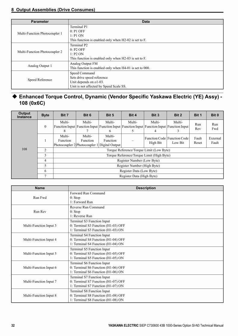
Enhanced Torque Control, Dynamic (Vendor Specific Yaskawa Electric (YE) Assy) - 108 (0x6C)
Multi-Function Photocoupler 1
Terminal P10: P1 OFF1: P1 ONThis function is enabled only when H2-02 is set to F.
Multi-Function Photocoupler 2
Terminal P20: P2 OFF1: P2 ONThis function is enabled only when H2-03 is set to F.
Analog Output 1 Analog Output FMThis function is enabled only when H4-01 is set to 000.
Speed Reference
Speed CommandSets drive speed referenceUnit depends on o1-03.Unit is not affected by Speed Scale SS.
Output Instance Byte Bit 7 Bit 6 Bit 5 Bit 4 Bit 3 Bit 2 Bit 1 Bit 0
108
0Multi-
Function Input 8
Multi-Function Input
7
Multi-Function Input
6
Multi-Function Input
5
Multi-Function Input
4
Multi-Function Input
3
RunRev
RunFwd
1Multi-
Function Photocoupler 2
Multi-Function
Photocoupler 1
Multi-Function
Digital Output– Function Code
High BitFunction Code
Low BitFaultReset
ExternalFault
2 Torque Reference/Torque Limit (Low Byte)3 Torque Reference/Torque Limit (High Byte)4 Register Number (Low Byte)5 Register Number (High Byte)6 Register Data (Low Byte)7 Register Data (High Byte)
Name Description
Run FwdForward Run Command0: Stop1: Forward Run
Run RevReverse Run Command0: Stop1: Reverse Run
Multi-Function Input 3Terminal S3 Function Input0: Terminal S3 Function (H1-03) OFF1: Terminal S3 Function (H1-03) ON
Multi-Function Input 4Terminal S4 Function Input0: Terminal S4 Function (H1-04) OFF1: Terminal S4 Function (H1-04) ON
Multi-Function Input 5Terminal S5 Function Input0: Terminal S5 Function (H1-05) OFF1: Terminal S5 Function (H1-05) ON
Multi-Function Input 6Terminal S6 Function Input0: Terminal S6 Function (H1-06) OFF1: Terminal S6 Function (H1-06) ON
Multi-Function Input 7Terminal S7 Function Input0: Terminal S7 Function (H1-07) OFF1: Terminal S7 Function (H1-07) ON
Multi-Function Input 8Terminal S8 Function Input0: Terminal S8 Function (H1-08) OFF1: Terminal S8 Function (H1-08) ON
Parameter Data

8 Output Assemblies (Drive Consumes)
YASKAWA ELECTRIC SIEP C730600 43B 1000-Series Option SI-N3 Technical Manual 33
Note: This is a paired assembly (108/158).Note: Refer to the MEMOBUS/Modbus Data Table in the drive Technical Manual for a list of monitor data using the MEMOBUS/
Modbus message area.
Speed Command 1 (Vendor Specific Yaskawa Electric (YE) Assy) - 120 (0x78)
External FaultExternal Fault EF00: No External Fault (EF0)1: External Fault (EF0)
Fault ResetFault Reset0: No Fault Reset1: Fault Reset
Function Code MEMOBUS/Modbus Function CodeRefer to Function Code Decode Table on page 29.
Multi-Function Digital Output
Terminal M1/M20: M1/M2 OFF1: M1/M2 ONThis function is enabled only when H2-01 is set to F.
Multi-Function Photocoupler 1
Terminal P10: P1 OFF1: P1 ONThis function is enabled only when H2-02 is set to F.
Multi-Function Photocoupler 2
Terminal P20: P2 OFF1: P2 ONThis function is enabled only when H2-03 is set to F.
Torque Reference/Torque Limit
Torque Reference/Torque LimitSets the torque reference and torque limit in units of 0.1%.Sets the torque reference when using torque control (d5-01 = 1).Sets the torque limit when using speed control (d5-01 = 0).The torque reference and torque limit are disabled when F6-06 = 0.
Register Number MEMOBUS/Modbus Register Number <1>
Register Data MEMOBUS/Modbus Register Data
<1> Register numbers 0x0001 and 0x0009 are disabled.
Output Instance Byte Bit 7 Bit 6 Bit 5 Bit 4 Bit 3 Bit 2 Bit 1 Bit 0
120
0Multi-
Function Input 8
Multi-Function Input 7
Multi-Function Input 6
Multi-Function Input 5
Multi-Function Input 4
Multi-Function Input 3
RunRev
RunFwd
1 – – – – – – FaultReset
ExternalFault
2 Speed Reference (Low Byte)3 Speed Reference (High Byte)
Parameter Data
Run FwdForward Run Command0: Stop1: Forward Run
Run RevReverse Run Command0: Stop1: Reverse Run
Multi-Function Input 3Terminal S3 Function Input0: Terminal S3 Function (H1-03) OFF1: Terminal S3 Function (H1-03) ON
Multi-Function Input 4Terminal S4 Function Input0: Terminal S4 Function (H1-04) OFF1: Terminal S4 Function (H1-04) ON
Multi-Function Input 5Terminal S5 Function Input0: Terminal S5 Function (H1-05) OFF1: Terminal S5 Function (H1-05) ON
Name Description

8 Output Assemblies (Drive Consumes)
34 YASKAWA ELECTRIC SIEP C730600 43B 1000-Series Option SI-N3 Technical Manual
Torque Command 1 (Vendor Specific Yaskawa Electric (YE) Assy) - 121 (0x79)
Multi-Function Input 6Terminal S6 Function Input0: Terminal S6 Function (H1-06) OFF1: Terminal S6 Function (H1-06) ON
Multi-Function Input 7Terminal S7 Function Input0: Terminal S7 Function (H1-07) OFF1: Terminal S7 Function (H1-07) ON
Multi-Function Input 8Terminal S8 Function Input0: Terminal S8 Function (H1-08) OFF1: Terminal S8 Function (H1-08) ON
External FaultExternal Fault EF00: No External Fault (EF0)1: External Fault (EF0)
Fault ResetFault Reset0: No Fault Reset1: Fault Reset
Speed Reference
Speed CommandSets drive speed referenceUnit depends on o1-03.Unit is not affected by Speed Scale SS.
Output Instance Byte Bit 7 Bit 6 Bit 5 Bit 4 Bit 3 Bit 2 Bit 1 Bit 0
121
0Multi-
Function Input 8
Multi-Function Input 7
Multi-Function Input 6
Multi-Function Input 5
Multi-Function Input 4
Multi-Function Input 3
RunRev
RunFwd
1 – – – – – – FaultReset
ExternalFault
2 Torque Reference/Torque Limit (Low Byte)3 Torque Reference/Torque Limit (High Byte)
Parameter Data
Run FwdForward Run Command0: Stop1: Forward Run
Run RevReverse Run Command0: Stop1: Reverse Run
Multi-Function Input 3Terminal S3 Function Input0: Terminal S3 Function (H1-03) OFF1: Terminal S3 Function (H1-03) ON
Multi-Function Input 4Terminal S4 Function Input0: Terminal S4 Function (H1-04) OFF1: Terminal S4 Function (H1-04) ON
Multi-Function Input 5Terminal S5 Function Input0: Terminal S5 Function (H1-05) OFF1: Terminal S5 Function (H1-05) ON
Multi-Function Input 6Terminal S6 Function Input0: Terminal S6 Function (H1-06) OFF1: Terminal S6 Function (H1-06) ON
Multi-Function Input 7Terminal S7 Function Input0: Terminal S7 Function (H1-07) OFF1: Terminal S7 Function (H1-07) ON
Multi-Function Input 8Terminal S8 Function Input0: Terminal S8 Function (H1-08) OFF1: Terminal S8 Function (H1-08) ON
External FaultExternal Fault EF00: No External Fault (EF0)1: External Fault (EF0)
Parameter Data

8 Output Assemblies (Drive Consumes)
YASKAWA ELECTRIC SIEP C730600 43B 1000-Series Option SI-N3 Technical Manual 35
Speed Command 2 (Vendor Specific Yaskawa Electric (YE) Assy) - 122 (0x7A)
Fault ResetFault Reset0: No Fault Reset1: Fault Reset
Torque Reference/Torque Limit
Torque Reference/Torque LimitSets the torque reference and torque limit in units of 0.1%.Sets the torque reference when using torque control (d5-01 = 1).Sets the torque limit when using speed control (d5-01 = 0).The torque reference and torque limit are disabled when F6-06 = 0.
Output Instance Byte Bit 7 Bit 6 Bit 5 Bit 4 Bit 3 Bit 2 Bit 1 Bit 0
122
0Multi-
Function Input 8
Multi-Function Input 7
Multi-Function Input 6
Multi-Function Input 5
Multi-Function Input 4
Multi-Function Input 3
RunRev
RunFwd
1 – – – – – – FaultReset
ExternalFault
2 Speed Reference (Low Byte)3 Speed Reference (High Byte)4 NetRef5 NetCtrl
Parameter Data
Run FwdForward Run Command0: Stop1: Forward Run
Run RevReverse Run Command0: Stop1: Reverse Run
Multi-Function Input 3Terminal S3 Function Input0: Terminal S3 Function (H1-03) OFF1: Terminal S3 Function (H1-03) ON
Multi-Function Input 4Terminal S4 Function Input0: Terminal S4 Function (H1-04) OFF1: Terminal S4 Function (H1-04) ON
Multi-Function Input 5Terminal S5 Function Input0: Terminal S5 Function (H1-05) OFF1: Terminal S5 Function (H1-05) ON
Multi-Function Input 6Terminal S6 Function Input0: Terminal S6 Function (H1-06) OFF1: Terminal S6 Function (H1-06) ON
Multi-Function Input 7Terminal S7 Function Input0: Terminal S7 Function (H1-07) OFF1: Terminal S7 Function (H1-07) ON
Multi-Function Input 8Terminal S8 Function Input0: Terminal S8 Function (H1-08) OFF1: Terminal S8 Function (H1-08) ON
External FaultExternal Fault EF00: No External Fault (EF0)1: External Fault (EF0)
Fault ResetFault Reset0: No Fault Reset1: Fault Reset
Speed Reference
Speed CommandSets drive speed referenceUnit depends on o1-03.Unit is not affected by Speed Scale SS.
NetRef Speed reference form Network0x00: Depends on b1-010x01: Enables the speed reference from network
Parameter Data

8 Output Assemblies (Drive Consumes)
36 YASKAWA ELECTRIC SIEP C730600 43B 1000-Series Option SI-N3 Technical Manual
Torque Command 2 (Vendor Specific Yaskawa Electric (YE) Assy) - 123 (0x7B)
NetCtrl Run command form Network0x00: Depends on b1-020x01: Enables the run command from network
Output Instance Byte Bit 7 Bit 6 Bit 5 Bit 4 Bit 3 Bit 2 Bit 1 Bit 0
123
0Multi-
Function Input 8
Multi-Function Input 7
Multi-Function Input 6
Multi-Function Input 5
Multi-Function Input 4
Multi-Function Input 3
RunRev
RunFwd
1 – – – – – – FaultReset
ExternalFault
2 Torque Reference/Torque Limit (Low Byte)3 Torque Reference/Torque Limit (High Byte)4 NetRef5 NetCtrl
Parameter Data
Run FwdForward Run Command0: Stop1: Forward Run
Run RevReverse Run Command0: Stop1: Reverse Run
Multi-Function Input 3Terminal S3 Function Input0: Terminal S3 Function (H1-03) OFF1: Terminal S3 Function (H1-03) ON
Multi-Function Input 4Terminal S4 Function Input0: Terminal S4 Function (H1-04) OFF1: Terminal S4 Function (H1-04) ON
Multi-Function Input 5Terminal S5 Function Input0: Terminal S5 Function (H1-05) OFF1: Terminal S5 Function (H1-05) ON
Multi-Function Input 6Terminal S6 Function Input0: Terminal S6 Function (H1-06) OFF1: Terminal S6 Function (H1-06) ON
Multi-Function Input 7Terminal S7 Function Input0: Terminal S7 Function (H1-07) OFF1: Terminal S7 Function (H1-07) ON
Multi-Function Input 8Terminal S8 Function Input0: Terminal S8 Function (H1-08) OFF1: Terminal S8 Function (H1-08) ON
External FaultExternal Fault EF00: No External Fault (EF0)1: External Fault (EF0)
Fault ResetFault Reset0: No Fault Reset1: Fault Reset
Torque Reference/Torque Limit
Torque Reference/Torque LimitSets the torque reference and torque limit in units of 0.1%.Sets the torque reference when using torque control (d5-01 = 1).Sets the torque limit when using speed control (d5-01 = 0).The torque reference and torque limit are disabled when F6-06 = 0.
NetRef Speed reference from Network0x00: Depends on b1-010x01: Enables the speed reference from network
NetCtrl Run command from Network0x00: Depends on b1-020x01: Enables the run command from network
Parameter Data
8 Output Assemblies (Drive Consumes)
YASKAWA ELECTRIC SIEP C730600 43B 1000-Series Option SI-N3 Technical Manual 37
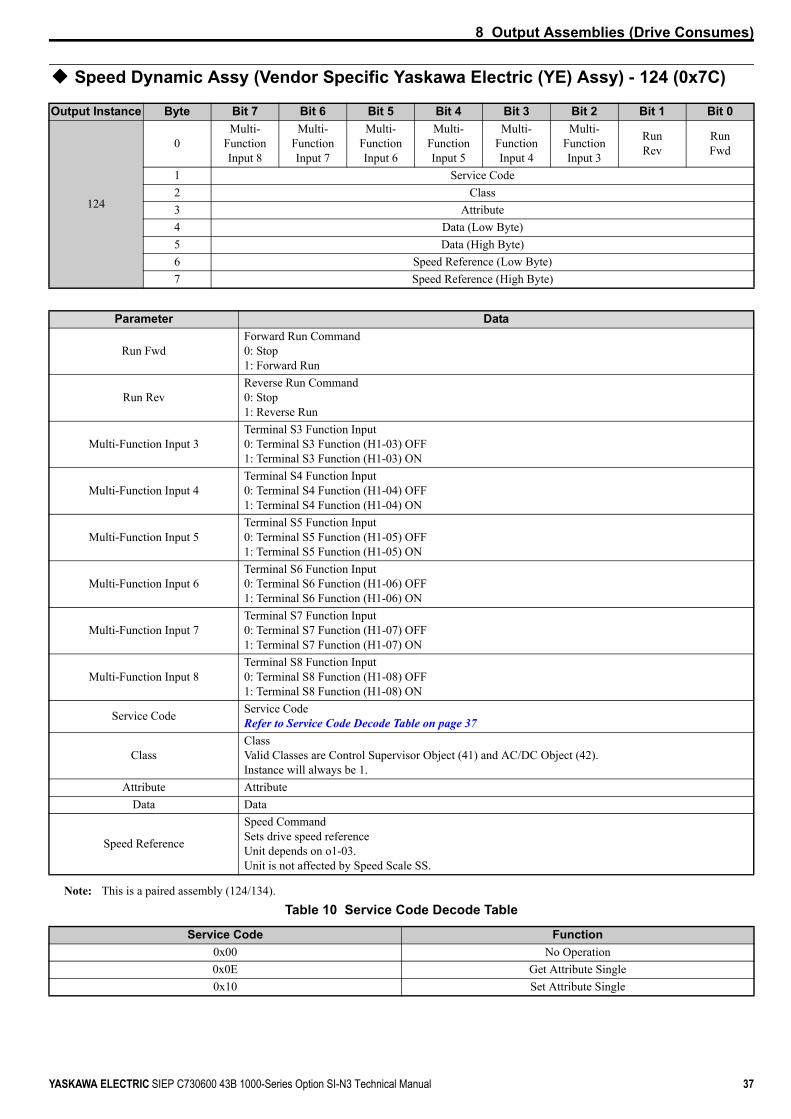
Speed Dynamic Assy (Vendor Specific Yaskawa Electric (YE) Assy) - 124 (0x7C)
Note: This is a paired assembly (124/134).Table 10 Service Code Decode Table
Output Instance Byte Bit 7 Bit 6 Bit 5 Bit 4 Bit 3 Bit 2 Bit 1 Bit 0
124
0Multi-
Function Input 8
Multi-Function Input 7
Multi-Function Input 6
Multi-Function Input 5
Multi-Function Input 4
Multi-Function Input 3
RunRev
RunFwd
1 Service Code2 Class3 Attribute4 Data (Low Byte)5 Data (High Byte)6 Speed Reference (Low Byte)7 Speed Reference (High Byte)
Parameter Data
Run FwdForward Run Command0: Stop1: Forward Run
Run RevReverse Run Command0: Stop1: Reverse Run
Multi-Function Input 3Terminal S3 Function Input0: Terminal S3 Function (H1-03) OFF1: Terminal S3 Function (H1-03) ON
Multi-Function Input 4Terminal S4 Function Input0: Terminal S4 Function (H1-04) OFF1: Terminal S4 Function (H1-04) ON
Multi-Function Input 5Terminal S5 Function Input0: Terminal S5 Function (H1-05) OFF1: Terminal S5 Function (H1-05) ON
Multi-Function Input 6Terminal S6 Function Input0: Terminal S6 Function (H1-06) OFF1: Terminal S6 Function (H1-06) ON
Multi-Function Input 7Terminal S7 Function Input0: Terminal S7 Function (H1-07) OFF1: Terminal S7 Function (H1-07) ON
Multi-Function Input 8Terminal S8 Function Input0: Terminal S8 Function (H1-08) OFF1: Terminal S8 Function (H1-08) ON
Service Code Service CodeRefer to Service Code Decode Table on page 37
ClassClassValid Classes are Control Supervisor Object (41) and AC/DC Object (42).Instance will always be 1.
Attribute AttributeData Data
Speed Reference
Speed CommandSets drive speed referenceUnit depends on o1-03.Unit is not affected by Speed Scale SS.
Service Code Function0x00 No Operation0x0E Get Attribute Single0x10 Set Attribute Single

8 Output Assemblies (Drive Consumes)
38 YASKAWA ELECTRIC SIEP C730600 43B 1000-Series Option SI-N3 Technical Manual
Torque Dynamic Assy (Vendor Specific Yaskawa Electric (YE) Assy) - 125 (0x7D)
Note: This is a paired assembly (125/135).
Output Instance Byte Bit 7 Bit 6 Bit 5 Bit 4 Bit 3 Bit 2 Bit 1 Bit 0
125
0Multi-
FunctionInput 8
Multi-FunctionInput 7
Multi-FunctionInput 6
Multi-FunctionInput 5
Multi-FunctionInput 4
Multi-FunctionInput 3
RunRev
RunFwd
1 Function Code2 Class3 Attribute4 Data (Low Byte)5 Data (High Byte)6 Torque Reference/Torque Limit (Low Byte)7 Torque Reference/Torque Limit (High Byte)
Parameter Data
Run FwdForward Run Command0: Stop1: Forward Run
Run RevReverse Run Command0: Stop1: Reverse Run
Multi-Function Input 3Terminal S3 Function Input0: Terminal S3 Function (H1-03) OFF1: Terminal S3 Function (H1-03) ON
Multi-Function Input 4Terminal S4 Function Input0: Terminal S4 Function (H1-04) OFF1: Terminal S4 Function (H1-04) ON
Multi-Function Input 5Terminal S5 Function Input0: Terminal S5 Function (H1-05) OFF1: Terminal S5 Function (H1-05) ON
Multi-Function Input 6Terminal S6 Function Input0: Terminal S6 Function (H1-06) OFF1: Terminal S6 Function (H1-06) ON
Multi-Function Input 7Terminal S7 Function Input0: Terminal S7 Function (H1-07) OFF1: Terminal S7 Function (H1-07) ON
Multi-Function Input 8Terminal S8 Function Input0: Terminal S8 Function (H1-08) OFF1: Terminal S8 Function (H1-08) ON
Service Code Service CodeRefer to Service Code Decode Table on page 37
ClassClassValid Classes are Control Supervisor Object (41) and AC/DC Object (42).Instance will always be 1.
Attribute AttributeData Data
Torque Reference/Torque Limit
Torque Reference/Torque LimitSets the torque reference and torque limit in units of 0.1%.Sets the torque reference when using torque control (d5-01 = 1).Sets the torque limit when using speed control (d5-01 = 0).The torque reference and torque limit are disabled when F6-06 = 0.

8 Output Assemblies (Drive Consumes)
YASKAWA ELECTRIC SIEP C730600 43B 1000-Series Option SI-N3 Technical Manual 39
Speed/Torque Assy (Vendor Specific Yaskawa Electric (YE) Assy) - 126 (0x7E)
Output Instance Byte Bit 7 Bit 6 Bit 5 Bit 4 Bit 3 Bit 2 Bit 1 Bit 0
126
0Multi-
FunctionInput 8
Multi-FunctionInput 7
Multi-FunctionInput 6
Multi-FunctionInput 5
Multi-FunctionInput 4
Multi-FunctionInput 3
RunRev
RunFwd
1 – – – – – – FaultReset
ExternalFault
2 Speed Reference (Low Byte) 3 Speed Reference (High Byte) 4 Torque Reference/Torque Limit (Low Byte)5 Torque Reference/Torque Limit (High Byte)6 Torque Compensation (Low Byte)7 Torque Compensation (High Byte)
Parameter Data
Run FwdForward Run Command0: Stop1: Forward Run
Run RevReverse Run Command0: Stop1: Reverse Run
Multi-Function Input 3Terminal S3 Function Input0: Terminal S3 Function (H1-03) OFF1: Terminal S3 Function (H1-03) ON
Multi-Function Input 4Terminal S4 Function Input0: Terminal S4 Function (H1-04) OFF1: Terminal S4 Function (H1-04) ON
Multi-Function Input 5Terminal S5 Function Input0: Terminal S5 Function (H1-05) OFF1: Terminal S5 Function (H1-05) ON
Multi-Function Input 6Terminal S6 Function Input0: Terminal S6 Function (H1-06) OFF1: Terminal S6 Function (H1-06) ON
Multi-Function Input 7Terminal S7 Function Input0: Terminal S7 Function (H1-07) OFF1: Terminal S7 Function (H1-07) ON
Multi-Function Input 8Terminal S8 Function Input0: Terminal S8 Function (H1-08) OFF1: Terminal S8 Function (H1-08) ON
External FaultExternal Fault EF00: No External Fault (EF0)1: External Fault (EF0)
Fault ResetFault Reset0: No Fault Reset1: Fault Reset
Speed Reference
Speed CommandSets drive speed referenceUnit depends on o1-03.Unit is not affected by Speed Scale SS.
Torque Reference/Torque Limit
Torque Reference/Torque LimitSets the torque reference and torque limit in units of 0.1%.Sets the torque reference when using torque control (d5-01 = 1).Sets the torque limit when using speed control (d5-01 = 0).The torque reference and torque limit are disabled when F6-06 = 0.
Torque Compensation Sets the amount of torque compensation.Set in units of 0.1%.
40 YASKAWA ELECTRIC SIEP C730600 43B 1000-Series Option SI-N3 Technical Manual
9 Input Assemblies (Drive Produces)
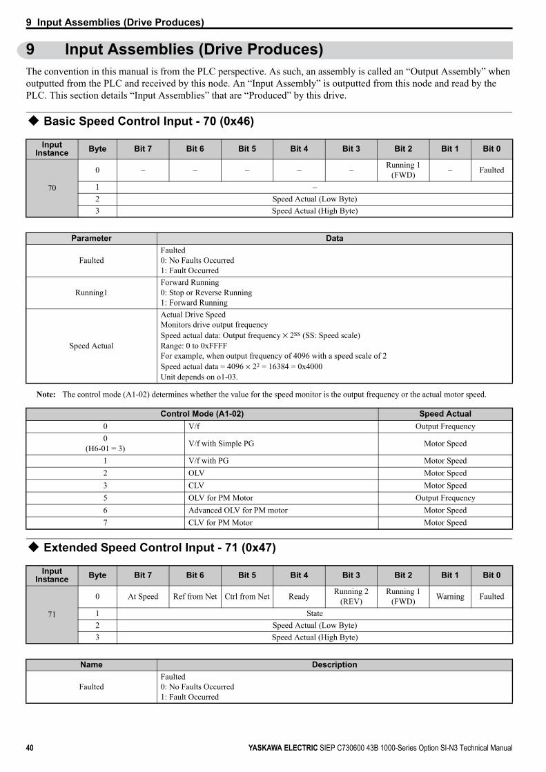
9 Input Assemblies (Drive Produces)The convention in this manual is from the PLC perspective. As such, an assembly is called an “Output Assembly” when outputted from the PLC and received by this node. An “Input Assembly” is outputted from this node and read by the PLC. This section details “Input Assemblies” that are “Produced” by this drive.
Basic Speed Control Input - 70 (0x46)
Note: The control mode (A1-02) determines whether the value for the speed monitor is the output frequency or the actual motor speed.
Extended Speed Control Input - 71 (0x47)
Input Instance Byte Bit 7 Bit 6 Bit 5 Bit 4 Bit 3 Bit 2 Bit 1 Bit 0
70
0 – – – – – Running 1(FWD) – Faulted
1 –2 Speed Actual (Low Byte)3 Speed Actual (High Byte)
Parameter Data
FaultedFaulted0: No Faults Occurred1: Fault Occurred
Running1Forward Running0: Stop or Reverse Running1: Forward Running
Speed Actual
Actual Drive SpeedMonitors drive output frequencySpeed actual data: Output frequency × 2SS (SS: Speed scale)Range: 0 to 0xFFFFFor example, when output frequency of 4096 with a speed scale of 2Speed actual data = 4096 × 22 = 16384 = 0x4000Unit depends on o1-03.
Control Mode (A1-02) Speed Actual0 V/f Output Frequency0
(H6-01 = 3) V/f with Simple PG Motor Speed
1 V/f with PG Motor Speed2 OLV Motor Speed3 CLV Motor Speed5 OLV for PM Motor Output Frequency6 Advanced OLV for PM motor Motor Speed7 CLV for PM Motor Motor Speed
Input Instance Byte Bit 7 Bit 6 Bit 5 Bit 4 Bit 3 Bit 2 Bit 1 Bit 0
71
0 At Speed Ref from Net Ctrl from Net Ready Running 2(REV)
Running 1(FWD) Warning Faulted
1 State2 Speed Actual (Low Byte)3 Speed Actual (High Byte)
Name Description
FaultedFaulted0: No Faults Occurred1: Fault Occurred

9 Input Assemblies (Drive Produces)
YASKAWA ELECTRIC SIEP C730600 43B 1000-Series Option SI-N3 Technical Manual 41
Speed and Torque Control Input - 72 (0x48)
WarningWarning0: No Warning Occurred1: Warning Occurred
Running 1 (FWD)Forward Running0: Stop or Reverse Running1: Forward Running
Running 2 (REV)Reverse Running0: Stop or Forward Running1: Reverse Running
ReadyDrive Ready0: Not Ready1: Ready
Ctrl from NetStatus of Run command from Network0: Run command is not from network1: Run command is from network
Ref from NetStatus of Speed reference from Network0: Speed reference is not from network1: Speed reference is from network
At SpeedSpeed Agree0: No Speed Agree1: Actual speed at speed reference
State
Drive Status2: Processing3: Ready (Stopped)4: Awaiting Run command5: Ramping to stop6: Fault stop7: Fault
Speed Actual
Actual Drive SpeedMonitors drive output frequencySpeed actual data: Output frequency × 2SS (SS: Speed scale)Range: 0 to 0xFFFFFor example, when output frequency of 4096 with a speed scale of 2Speed actual data = 4096 × 22 = 16384 = 0x4000Unit depends on o1-03.
Input Instance Byte Bit 7 Bit 6 Bit 5 Bit 4 Bit 3 Bit 2 Bit 1 Bit 0
72
0 – – – – – Running 1(FWD) – Faulted
1 –2 Speed Actual (Low Byte)3 Speed Actual (High Byte)4 Torque Actual (Low Byte)5 Torque Actual (High Byte)
Name Description
FaultedFaulted0: No Faults Occurred1: Fault Occurred
Running 1Forward Running0: Stop or Reverse Running1: Forward Running
Name Description

9 Input Assemblies (Drive Produces)
42 YASKAWA ELECTRIC SIEP C730600 43B 1000-Series Option SI-N3 Technical Manual
Extended Speed and Torque Control Input - 73 (0x49)
Speed Actual
Actual Drive SpeedMonitors drive output frequencySpeed actual data: Output frequency × 2SS (SS: Speed scale)Range: 0 to 0xFFFFFor example, when output frequency of 4096 with a speed scale of 2Speed actual data = 4096 × 22 = 16384 = 0x4000Unit depends on o1-03.
Torque ActualOutput TorqueShows the torque reference.Value displays in 0.1% units.
Input Instance Byte Bit 7 Bit 6 Bit 5 Bit 4 Bit 3 Bit 2 Bit 1 Bit 0
73
0 At Speed Ref from Net Ctrl from Net Ready Running 2(REV)
Running 1(FWD) Warning Faulted
1 State2 Speed Actual (Low Byte)3 Speed Actual (High Byte)4 Torque Actual (Low Byte)5 Torque Actual (High Byte)
Name Description
FaultedFaulted0: No Faults Occurred1: Fault Occurred
WarningWarning0: No Warning Occurred1: Warning Occurred
Running 1 (FWD)Forward Running0: Stop or Reverse Running1: Forward Running
Running 2 (REV)Reverse Running0: Stop or Forward Running1: Reverse Running
ReadyDrive Ready0: Not Ready1: Ready
Ctrl from NetStatus of Run command from Network0: Run command is not from network1: Run command is from network
Ref from NetStatus of Speed reference from Network0: Speed reference is not from network1: Speed reference is from network
At SpeedSpeed Agree0: No Speed Agree1: Actual speed at speed reference
State
2: Processing3: Ready (Stopped)4: Awaiting Run command5: Ramping to stop6: Fault stop7: Fault
Speed Actual
Actual Drive SpeedMonitors drive output frequencySpeed actual data: Output frequency / 2SS (SS: Speed scale)Range: 0 to 0xFFFFFor example, when output frequency of 4096 with a speed scale of 2Speed actual data = 4096 × 22 = 16384 = 0x4000Unit depends on o1-03.
Name Description

9 Input Assemblies (Drive Produces)
YASKAWA ELECTRIC SIEP C730600 43B 1000-Series Option SI-N3 Technical Manual 43
Speed Status (Vendor Specific Yaskawa Electric (YE) Assy) - 130 (0x82)
Torque ActualOutput TorqueShows the torque reference.Value displays in 0.1% units.
Input Instance Byte Bit 7 Bit 6 Bit 5 Bit 4 Bit 3 Bit 2 Bit 1 Bit 0
130
0 FAULT ALARM READY SpeedAgree Reset REV
Running ZSP Running
1 ZSV –Multi-
FunctionPhotocoupler 2
Multi-Function
Photocoupler 1
Multi-Function
Digital Output
LOCAL/REMOTE Uv –
2 Output Frequency (Low Byte)3 Output Frequency (High Byte)
Parameter Data
RunningRunning0: Stop1: Forward or Reverse Running
ZSPZero Speed0: Running1: Stop or DC Injection Braking
REV RunningReverse Running0: Not Reverse Running1: Reverse Running
ResetReset0: No Reset1: Reset
Speed AgreeSpeed Agree0: No Speed Agree1: Actual speed at speed reference
READYDrive Ready0: Not Ready1: Ready
ALARMDrive Alarm0: No Drive Alarm1: Alarm
FAULTDrive Fault0: No Drive Fault1: Fault
UvUndervoltage0: No Undervoltage1: Undervoltage
LOCAL/REMOTEStatus of Run command from Network0: Run command is not from network1: Run command is from network
Multi-Function Digital OutputTerminal M1/M20: Terminal M1/M2 OFF1: Terminal M1/M2 ON
Multi-Function Photocoupler 1Terminal P10: Terminal P1 OFF1: Terminal P1 ON
Multi-Function Photocoupler 2Terminal P20: Terminal P2 OFF1: Terminal P2 ON
ZSVZero Servo Completed0: –1: Completed
Name Description

9 Input Assemblies (Drive Produces)
44 YASKAWA ELECTRIC SIEP C730600 43B 1000-Series Option SI-N3 Technical Manual
Current Status (Vendor Specific Yaskawa Electric (YE) Assy) - 131 (0x83)
Output Frequency
Actual Drive SpeedMonitors drive output frequencyUnit depends on o1-03.Unit is not affected by Speed Scale SS.
Input Instance Byte Bit 7 Bit 6 Bit 5 Bit 4 Bit 3 Bit 2 Bit 1 Bit 0
131
0 FAULT ALARM READY SpeedAgree Reset REV
Running ZSP Running
1 ZSV –Multi-
FunctionPhotocoupler 2
Multi-Function
Photocoupler 1
Multi-Function
Digital Output
LOCAL/REMOTE Uv –
2 Actual Current (Low Byte)3 Actual Current (High Byte)
Parameter Data
RunningRunning0: Stop1: Forward or Reverse Running
ZSPZero Speed0: Running1: Stop or DC Injection Braking
REV RunningReverse Running0: Not Reverse Running1: Reverse Running
ResetReset0: No Reset1: Reset
Speed AgreeSpeed Agree0: No Speed Agree1: Actual speed at speed reference
READYDrive Ready0: Not Ready1: Ready
ALARMDrive Alarm0: No Drive Alarm1: Alarm
FAULTDrive Fault0: No Drive Fault1: Fault
UvUndervoltage0: No Undervoltage1: Undervoltage
LOCAL/REMOTEStatus of Run command from Network0: Run command is not from network1: Run command is from network
Multi-Function Digital OutputTerminal M1/M20: Terminal M1/M2 OFF1: Terminal M1/M2 ON
Multi-Function Photocoupler 1Terminal P10: Terminal P1 OFF1: Terminal P1 ON
Multi-Function Photocoupler 2Terminal P20: Terminal P2 OFF1: Terminal P2 ON
ZSVZero Servo Completed0: –1: Completed
Parameter Data

9 Input Assemblies (Drive Produces)
YASKAWA ELECTRIC SIEP C730600 43B 1000-Series Option SI-N3 Technical Manual 45
Current & Speed Status (Vendor Specific Yaskawa Electric (YE) Assy) - 132 (0x84)
Actual Current
Actual Output CurrentMonitors drive output currentUnit is 0.1 AUnit is not affected by Current Scale CS.
Input Instance Byte Bit 7 Bit 6 Bit 5 Bit 4 Bit 3 Bit 2 Bit 1 Bit 0
132
0 FAULT ALARM READY SpeedAgree Reset REV
Running ZSP Running
1 ZSV –Multi-
FunctionPhotocoupler 2
Multi-Function
Photocoupler 1
Multi-Function
Digital Output
LOCAL/REMOTE Uv –
2 Actual Current (Low Byte)3 Actual Current (High Byte)4 Output Frequency (Low Byte)5 Output Frequency (High Byte)
Parameter Data
RunningRunning0: Stop1: Forward or Reverse Running
ZSPZero Speed0: Running1: Stop or DC Injection Braking
REV RunningReverse Running0: Not Reverse Running1: Reverse Running
ResetReset0: No Reset1: Reset
Speed AgreeSpeed Agree0: No Speed Agree1: Actual speed at speed reference
READYDrive Ready0: Not Ready1: Ready
ALARMDrive Alarm0: No Drive Alarm1: Alarm
FAULTDrive Fault0: No Drive Fault1: Fault
UvUndervoltage0: No Undervoltage1: Undervoltage
LOCAL/REMOTEStatus of Run command from Network0: Run command is not from network1: Run command is from network
Multi-Function Digital OutputTerminal M1/M20: Terminal M1/M2 OFF1: Terminal M1/M2 ON
Multi-Function Photocoupler 1Terminal P10: Terminal P1 OFF1: Terminal P1 ON
Multi-Function Photocoupler 2Terminal P20: Terminal P2 OFF1: Terminal P2 ON
Parameter Data

9 Input Assemblies (Drive Produces)
46 YASKAWA ELECTRIC SIEP C730600 43B 1000-Series Option SI-N3 Technical Manual
Speed Status Dynamic Assy (Vendor Specific Yaskawa Electric (YE) Assy) - 134 (0x86)
ZSVZero Servo Completed0: –1: Completed
Actual Current
Actual Output CurrentMonitors drive output currentUnit is 0.1 AUnit is not affected by Current Scale CS.
Output Frequency
Actual Drive SpeedMonitors drive output frequencyUnit depends on o1-03.Unit is not affected by Speed Scale SS.
Input Instance Byte Bit 7 Bit 6 Bit 5 Bit 4 Bit 3 Bit 2 Bit 1 Bit 0
134
0 FAULT ALARM READY SpeedAgree Reset REV
Running ZSP Running
1 Service Code2 Class3 Attribute4 Data (Low Byte)5 Data (High Byte)6 Output Frequency (Low Byte)7 Output Frequency (High Byte)
Parameter Data
RunningRunning0: Stop1: Forward or Reverse Running
ZSPZero Speed0: Running1: Stop or DC Injection Braking
REV RunningReverse Running0: Not Reverse Running1: Reverse Running
ResetReset0: No Reset1: Reset
Speed AgreeSpeed Agree0: No Speed Agree1: Actual speed at speed reference
READYDrive Ready0: Not Ready1: Ready
ALARMDrive Alarm0: No Drive Alarm1: Alarm
FAULTDrive Fault0: No Drive Fault1: Fault
Service Code Service CodeRefer to Service Code Decode Table on page 37
ClassClassValid Classes are Control Supervisor Object (41) and AC/DC Object (42).Instance will always be 1.
Attribute Attribute
Data DataIf Service Code is 0x94, Data is Error Code.
Parameter Data

9 Input Assemblies (Drive Produces)
YASKAWA ELECTRIC SIEP C730600 43B 1000-Series Option SI-N3 Technical Manual 47
Note: This is a paired assembly (124/134).Table 11 Reply Mapping - 134
Current Status Dynamic Assy (Vendor Specific Yaskawa Electric (YE) Assy) - 135 (0x87)
Output Frequency
Actual Drive SpeedMonitors drive output frequencyUnit depends on o1-03.Unit is not affected by Speed Scale SS.
Byte Write Success Read Success Write Failure Read Failure Busy
Illegal Function
CodeFunction Code
Equals Zero
1 0x90 0x8E 0x94 0x94 0x8E/0x90 0x94 02 Class Number Class Number 0 0 Class Number 0 0
3 Attribute Number
Attribute Number 0 0 Attribute
Number 0 0
4 0 Data Low Byte DeviceNet Error Code
DeviceNet Error Code 0 0x08 0
5 0 Data High Byte 0xFF 0xFF 0 0xFF 0
Input Instance Byte Bit 7 Bit 6 Bit 5 Bit 4 Bit 3 Bit 2 Bit 1 Bit 0
135
0 FAULT ALARM READY SpeedAgree Reset REV
Running ZSP Running
1 Service Code2 Class 3 Attribute4 Data (Low Byte)5 Data (High Byte)6 Actual Current (Low Byte)7 Actual Current (High Byte)
Parameter Data
RunningRunning0: Stop1: Forward or Reverse Running
ZSPZero Speed0: Running1: Stop or DC Injection Braking
REV RunningReverse Running0: Not Reverse Running1: Reverse Running
ResetReset0: No Reset1: Reset
Speed AgreeSpeed Agree0: No Speed Agree1: Actual speed at speed reference
READYDrive Ready0: Not Ready1: Ready
ALARMDrive Alarm0: No Drive Alarm1: Alarm
FAULTDrive Fault0: No Drive Fault1: Fault
Parameter Data
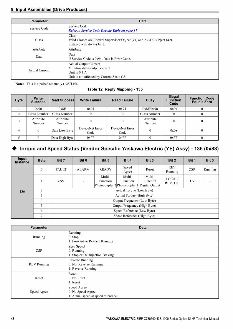
9 Input Assemblies (Drive Produces)
48 YASKAWA ELECTRIC SIEP C730600 43B 1000-Series Option SI-N3 Technical Manual
Note: This is a paired assembly (125/135).Table 12 Reply Mapping - 135
Torque and Speed Status (Vendor Specific Yaskawa Electric (YE) Assy) - 136 (0x88)
Service Code Service CodeRefer to Service Code Decode Table on page 37
ClassClassValid Classes are Control Supervisor Object (41) and AC/DC Object (42).Instance will always be 1.
Attribute Attribute
Data DataIf Service Code is 0x94, Data is Error Code.
Actual Current
Actual Output CurrentMonitors drive output currentUnit is 0.1 AUnit is not affected by Current Scale CS.
Byte Write Success Read Success Write Failure Read Failure Busy
Illegal Function
CodeFunction Code
Equals Zero
1 0x90 0x8E 0x94 0x94 0x8E/0x90 0x94 02 Class Number Class Number 0 0 Class Number 0 0
3 Attribute Number
Attribute Number 0 0 Attribute
Number 0 0
4 0 Data Low Byte DeviceNet Error Code
DeviceNet Error Code 0 0x08 0
5 0 Data High Byte 0xFF 0xFF 0 0xFF 0
Input Instance Byte Bit 7 Bit 6 Bit 5 Bit 4 Bit 3 Bit 2 Bit 1 Bit 0
136
0 FAULT ALARM READY SpeedAgree Reset REV
Running ZSP Running
1 ZSV -Multi-
FunctionPhotocoupler 2
Multi-Function
Photocoupler 1
Multi-Function
Digital Output
LOCAL/REMOTE Uv –
2 Actual Torque (Low Byte)3 Actual Torque (High Byte)4 Output Frequency (Low Byte)5 Output Frequency (High Byte)6 Speed Reference (Low Byte)7 Speed Reference (High Byte)
Parameter Data
RunningRunning0: Stop1: Forward or Reverse Running
ZSPZero Speed0: Running1: Stop or DC Injection Braking
REV RunningReverse Running0: Not Reverse Running1: Reverse Running
ResetReset0: No Reset1: Reset
Speed AgreeSpeed Agree0: No Speed Agree1: Actual speed at speed reference
Parameter Data

9 Input Assemblies (Drive Produces)
YASKAWA ELECTRIC SIEP C730600 43B 1000-Series Option SI-N3 Technical Manual 49
MEMOBUS/Modbus Message Reply (Vendor Specific Yaskawa Electric (YE) Assy) - 150 (0x96)
Note: This is a paired assembly (100/150).Table 13 Reply Mapping - 150
READYDrive Ready0: Not Ready1: Ready
ALARMDrive Alarm0: No Drive Alarm1: Alarm
FAULTDrive Fault0: No Drive Fault1: Fault
UvUndervoltage0: No Uv Fault1: Fault
LOCAL/REMOTEStatus of Run command from Network0: Run command is not from network1: Run command is from network
Multi-Function Digital OutputTerminal M1/M20: Terminal M1/M2 OFF1: Terminal M1/M2 ON
Multi-Function Photocoupler 1Terminal P10: Terminal P1 OFF1: Terminal P1 ON
Multi-Function Photocoupler 2Terminal P20: Terminal P2 OFF1: Terminal P2 ON
ZSVZero Servo Completed0: –1: Completed
Actual TorqueOutput TorqueShows the torque reference.Value displays in 0.1% units.
Output Frequency
Actual Drive SpeedMonitors drive output frequencyUnit depends on o1-03.Unit is not affected by Speed Scale SS.
Speed Reference
Frequency ReferenceMonitors drive frequency referenceUnit depends on o1-03.Unit is not affected by Speed Scale SS.
Input Instance Byte Bit 7 Bit 6 Bit 5 Bit 4 Bit 3 Bit 2 Bit 1 Bit 0
150
0 Function Code1 Register Number (High Byte)2 Register Number (Low Byte)3 Register Data (High Byte)4 Register Data (Low Byte)
Byte Write Success Read Success Write Failure Read Failure Illegal Function Code
Function Code
Equals Zero
0 0x10 0x03 0x90 0x83 Function Code Or-ed with 0x80 0
1Output Assembly Register Number
(High Byte)
Output Assembly Register Number
(High Byte)
Output Assembly Register Number
(High Byte)
Output Assembly Register Number
(High Byte)
Output Assembly Register Number
(High Byte)0
Parameter Data
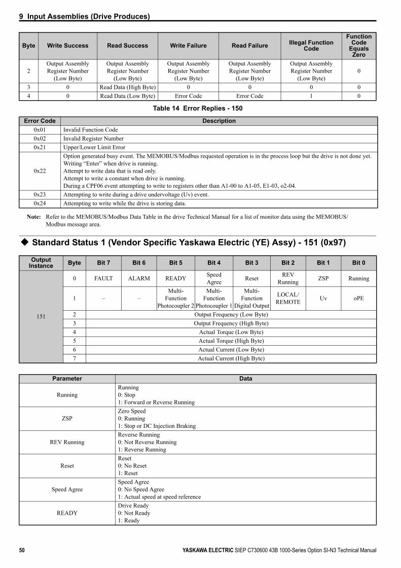
9 Input Assemblies (Drive Produces)
50 YASKAWA ELECTRIC SIEP C730600 43B 1000-Series Option SI-N3 Technical Manual
Table 14 Error Replies - 150
Note: Refer to the MEMOBUS/Modbus Data Table in the drive Technical Manual for a list of monitor data using the MEMOBUS/Modbus message area.
Standard Status 1 (Vendor Specific Yaskawa Electric (YE) Assy) - 151 (0x97)
2Output Assembly Register Number
(Low Byte)
Output Assembly Register Number
(Low Byte)
Output Assembly Register Number
(Low Byte)
Output Assembly Register Number
(Low Byte)
Output Assembly Register Number
(Low Byte)0
3 0 Read Data (High Byte) 0 0 0 04 0 Read Data (Low Byte) Error Code Error Code 1 0
Error Code Description0x01 Invalid Function Code0x02 Invalid Register Number0x21 Upper/Lower Limit Error
0x22
Option generated busy event. The MEMOBUS/Modbus requested operation is in the process loop but the drive is not done yet.Writing “Enter” when drive is running.Attempt to write data that is read only.Attempt to write a constant when drive is running.During a CPF06 event attempting to write to registers other than A1-00 to A1-05, E1-03, o2-04.
0x23 Attempting to write during a drive undervoltage (Uv) event.0x24 Attempting to write while the drive is storing data.
Output Instance Byte Bit 7 Bit 6 Bit 5 Bit 4 Bit 3 Bit 2 Bit 1 Bit 0
151
0 FAULT ALARM READY SpeedAgree Reset REV
Running ZSP Running
1 – –Multi-
FunctionPhotocoupler 2
Multi-Function
Photocoupler 1
Multi-Function
Digital Output
LOCAL/REMOTE Uv oPE
2 Output Frequency (Low Byte)3 Output Frequency (High Byte)4 Actual Torque (Low Byte)5 Actual Torque (High Byte)6 Actual Current (Low Byte)7 Actual Current (High Byte)
Parameter Data
RunningRunning0: Stop1: Forward or Reverse Running
ZSPZero Speed0: Running1: Stop or DC Injection Braking
REV RunningReverse Running0: Not Reverse Running1: Reverse Running
ResetReset0: No Reset1: Reset
Speed AgreeSpeed Agree0: No Speed Agree1: Actual speed at speed reference
READYDrive Ready0: Not Ready1: Ready
Byte Write Success Read Success Write Failure Read Failure Illegal Function Code
Function Code
Equals Zero

9 Input Assemblies (Drive Produces)
YASKAWA ELECTRIC SIEP C730600 43B 1000-Series Option SI-N3 Technical Manual 51
Standard Status 2 (Vendor Specific Yaskawa Electric (YE) Assy) -152 (0x98)
ALARMDrive Alarm0: No Drive Alarm1: Alarm
FAULTDrive Fault0: No Drive Fault1: Fault
oPEoPE Fault0: No oPExx Fault1: oPExx
UvUndervoltage0: No Undervoltage1: Undervoltage
LOCAL/REMOTEStatus of Run command from Network0: Run command is not from network1: Run command is from network
Multi-Function Digital OutputTerminal M1/M20: Terminal M1/M2 OFF1: Terminal M1/M2 ON
Multi-Function Photocoupler 1Terminal P10: Terminal P1 OFF1: Terminal P1 ON
Multi-Function Photocoupler 2Terminal P20: Terminal P2 OFF1: Terminal P2 ON
Output Frequency
Actual Drive SpeedMonitors drive output frequencyUnit depends on o1-03.Unit is not affected by Speed Scale SS.
Actual TorqueOutput TorqueShows the torque reference.Value displays in 0.1% units.
Actual Current
Actual Output CurrentMonitors drive output currentUnit is 0.1 AUnit is not affected by Current Scale CS.
Input Instance Byte Bit 7 Bit 6 Bit 5 Bit 4 Bit 3 Bit 2 Bit 1 Bit 0
152
0 FAULT ALARM READY SpeedAgree Reset REV
Running ZSP Running
1 – –Multi-
FunctionPhotocoupler 2
Multi-Function
Photocoupler 1
Multi-Function
Digital Output
LOCAL/REMOTE Uv oPE
2 Output Frequency (Low Byte)3 Output Frequency (High Byte)4 Speed Reference (Low Byte)5 Speed Reference (High Byte)6 Actual Current (Low Byte)7 Actual Current (High Byte)
Parameter Data
RunningRunning0: Stop1: Forward or Reverse Running
ZSPZero Speed0: Running1: Stop or DC Injection Braking
Parameter Data

9 Input Assemblies (Drive Produces)
52 YASKAWA ELECTRIC SIEP C730600 43B 1000-Series Option SI-N3 Technical Manual
REV RunningReverse Running0: Not Reverse Running1: Reverse Running
ResetReset0: No Reset1: Reset
Speed AgreeSpeed Agree0: No Speed Agree1: Actual speed at speed reference
READYDrive Ready0: Not Ready1: Ready
ALARMDrive Alarm0: No Drive Alarm1: Alarm
FAULTDrive Fault0: No Drive Fault1: Fault
oPEoPE Fault0: No oPExx Fault1: oPExx
UvUndervoltage0: No Undervoltage1: Undervoltage
LOCAL/REMOTEStatus of Run command from Network0: Run command is not from network1: Run command is from network
Multi-Function Digital OutputTerminal M1/M20: Terminal M1/M2 OFF1: Terminal M1/M2 ON
Multi-Function Photocoupler 1Terminal P10: Terminal P1 OFF1: Terminal P1 ON
Multi-Function Photocoupler 2Terminal P20: Terminal P2 OFF1: Terminal P2 ON
Output Frequency
Actual Drive SpeedMonitors drive output frequencyUnit depends on o1-03.Unit is not affected by Speed Scale SS.
Frequency Reference
Frequency ReferenceMonitors drive frequency referenceUnit depends on o1-03.Unit is not affected by Speed Scale SS.
Actual Current
Actual Output CurrentMonitors drive output currentUnit is 0.1 AUnit is not affected by Current Scale CS.
Parameter Data

9 Input Assemblies (Drive Produces)
YASKAWA ELECTRIC SIEP C730600 43B 1000-Series Option SI-N3 Technical Manual 53
Enhanced Speed Status, Dynamic (Vendor Specific Yaskawa Electric (YE) Assy) - 155 (0x9B)
Output Instance Byte Bit 7 Bit 6 Bit 5 Bit 4 Bit 3 Bit 2 Bit 1 Bit 0
155
0 FAULT ALARM READY SpeedAgree Reset REV
Running ZSP Running
1Multi-
FunctionPhotocoupler 2
Multi-Function
Photocoupler 1
Multi-Function Digital Output
LOCAL /REMOTE
Function Code
High Bit
Function Code
Low BitUv oPE
2 Output Frequency (Low Byte)3 Output Frequency (High Byte)4 Register Number (Low Byte)5 Register Number (High Byte)6 Register Data (Low Byte)7 Register Data (High Byte)
Parameter Data
RunningRunning0: Stop1: Forward or Reverse Running
ZSPZero Speed0: Running1: Stop or DC Injection Braking
REV RunningReverse Running0: Not Reverse Running1: Reverse Running
ResetReset0: No Reset1: Reset
Speed AgreeSpeed Agree0: No Speed Agree1: Actual speed at speed reference
READYDrive Ready0: Not Ready1: Ready
ALARMDrive Alarm0: No Drive Alarm1: Alarm
FAULTDrive Fault0: No Drive Fault1: Fault
oPEoPE Fault0: No oPExx Fault1: oPExx
UvUndervoltage0: No Undervoltage1: Undervoltage
Function Code MEMOBUS/Modbus Function Code Refer to Function Code Decode Table on page 29
LOCAL/REMOTEStatus of Run command from Network0: Run command is not from network1: Run command is from network
Multi-Function Digital OutputTerminal M1/M20: Terminal M1/M2 OFF1: Terminal M1/M2 ON
Multi-Function Photocoupler 1Terminal P10: Terminal P1 OFF1: Terminal P1 ON

9 Input Assemblies (Drive Produces)
54 YASKAWA ELECTRIC SIEP C730600 43B 1000-Series Option SI-N3 Technical Manual
Note: This is a paired assembly (105/155).Note: Refer to the MEMOBUS/Modbus Data Table in the drive Technical Manual for a list of monitor data using the MEMOBUS/
Modbus message area.Table 15 Reply Mapping - 155
Table 16 Error Replies - 155
Note: Refer to the MEMOBUS/Modbus Data Table in the drive Technical Manual for a list of monitor data using the MEMOBUS/Modbus message area.
Enhanced Control Status (Vendor Specific Yaskawa Electric (YE) Assy) -156 (0x9C)
Multi-Function Photocoupler 2Terminal P20: Terminal P2 OFF1: Terminal P2 ON
Output Frequency
Actual Drive SpeedMonitors drive output frequencyUnit depends on o1-03.Unit is not affected by Speed Scale SS.
Register Number MEMOBUS/Modbus Register NumberRegister Data MEMOBUS/Modbus Register Data
Function Code Bits/Byte Write Success Read Success Write Failure Read Failure Function Code
Equal to 0 0Function Bits (High/Low) 1 1 1 1 0 1 0 1 0 0
4Output Assembly Register Number
(Low Byte)
Output Assembly Register Number
(Low Byte)
Output Assembly Register Number
(Low Byte)
Output Assembly Register Number
(Low Byte)0
5Output Assembly Register Number
(High Byte)
Output Assembly Register Number
(High Byte)
Output Assembly Register Number
(High Byte)
Output Assembly Register Number
(High Byte)0
6 0 Read Data (Low Byte) Error Code Error Code 07 0 Read Data (High Byte) 0 0 0
Error Code Description0x02 Invalid Register Number0x21 Upper/Lower Limit Error
0x22
Option generated busy event. The MEMOBUS/Modbus requested operation is in the process loop but the drive is not done yet.Writing “Enter” when drive is running.Attempt to write data that is read only.Attempt to write a parameter when drive is running.During a CPF06 event attempting to write to registers other than A1-00 to A1-05, E1-03, o2-04.
0x23 Attempting to write during a drive undervoltage (Uv) event.0x24 Attempting to write while the drive is storing data.
Input Instance Byte Bit 7 Bit 6 Bit 5 Bit 4 Bit 3 Bit 2 Bit 1 Bit 0
156
0 FAULT ALARM READY SpeedAgree Reset REV
Running ZSP Running
1Multi-
FunctionPhotocoupler 2
Multi-Function
Photocoupler 1
Multi-Function Digital Output
–Multi-
Function Input 4
Multi-Function Input 3
Multi-Function Input 2
Multi-Function Input 1
2 Output Frequency (Low Byte)3 Output Frequency (High Byte)4 –5 –6 Actual Current (Low Byte)7 Actual Current (High Byte)
Parameter Data
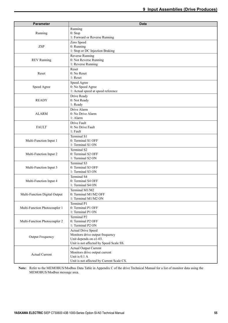
9 Input Assemblies (Drive Produces)
YASKAWA ELECTRIC SIEP C730600 43B 1000-Series Option SI-N3 Technical Manual 55
Note: Refer to the MEMOBUS/Modbus Data Table in Appendix C of the drive Technical Manual for a list of monitor data using the MEMOBUS/Modbus message area.
Parameter Data
RunningRunning0: Stop1: Forward or Reverse Running
ZSPZero Speed0: Running1: Stop or DC Injection Braking
REV RunningReverse Running0: Not Reverse Running1: Reverse Running
ResetReset0: No Reset1: Reset
Speed AgreeSpeed Agree0: No Speed Agree1: Actual speed at speed reference
READYDrive Ready0: Not Ready1: Ready
ALARMDrive Alarm0: No Drive Alarm1: Alarm
FAULTDrive Fault0: No Drive Fault1: Fault
Multi-Function Input 1 Terminal S10: Terminal S1 OFF1: Terminal S1 ON
Multi-Function Input 2Terminal S20: Terminal S2 OFF1: Terminal S2 ON
Multi-Function Input 3 Terminal S30: Terminal S3 OFF1: Terminal S3 ON
Multi-Function Input 4Terminal S40: Terminal S4 OFF1: Terminal S4 ON
Multi-Function Digital OutputTerminal M1/M20: Terminal M1/M2 OFF1: Terminal M1/M2 ON
Multi-Function Photocoupler 1Terminal P10: Terminal P1 OFF1: Terminal P1 ON
Multi-Function Photocoupler 2Terminal P20: Terminal P2 OFF1: Terminal P2 ON
Output Frequency
Actual Drive SpeedMonitors drive output frequencyUnit depends on o1-03.Unit is not affected by Speed Scale SS.
Actual Current
Actual Output CurrentMonitors drive output currentUnit is 0.1 AUnit is not affected by Current Scale CS.

9 Input Assemblies (Drive Produces)
56 YASKAWA ELECTRIC SIEP C730600 43B 1000-Series Option SI-N3 Technical Manual
Standard DI/DO Status (Vendor Specific Yaskawa Electric (YE) Assy) - 157 (0x9D)
Input Instance Byte Bit 7 Bit 6 Bit 5 Bit 4 Bit 3 Bit 2 Bit 1 Bit 0
157
0 FAULT ALARM READY SpeedAgree Reset REV
Running ZSP Running
1 – – – – – LOCAL/REMOTE Uv oPE
2Multi-
Function Input 8
Multi-Function Input 7
Multi-Function Input 6
Multi-Function Input 5
Multi-Function Input 4
Multi-Function Input 3
Multi-Function Input 2
Multi-Function Input 1
3 – –
Multi-Function
Photocoupler 2
Multi-Function
Photocoupler1
Multi-Function Digital Output
– – –
4 Analog Input 1 (Low Byte)5 Analog Input 1 (High Byte)6 Output Frequency (Low Byte)7 Output Frequency (High Byte)
Parameter Data
RunningRunning0: Stop1: Forward or Reverse Running
ZSPZero Speed0: Running1: Stop or DC Injection Braking
REV RunningReverse Running0: Not Reverse Running1: Reverse Running
ResetReset0: No Reset1: Reset
Speed AgreeSpeed Agree0: No Speed Agree1: Actual speed at speed reference
READYDrive Ready0: Not Ready1: Ready
ALARMDrive Alarm0: No Drive Alarm1: Alarm
FAULTDrive Fault0: No Drive Fault1: Fault
oPEoPE Fault0: No oPExx Fault1: oPExx
UvUndervoltage0: No Undervoltage1: Undervoltage
LOCAL/REMOTEStatus of Run command from Network0: Run command is not from network1: Run command is from network
Multi-Function Input 1Terminal S10: Terminal S1 OFF1: Terminal S1 ON
Multi-Function Input 2Terminal S20: Terminal S2 OFF1: Terminal S2 ON
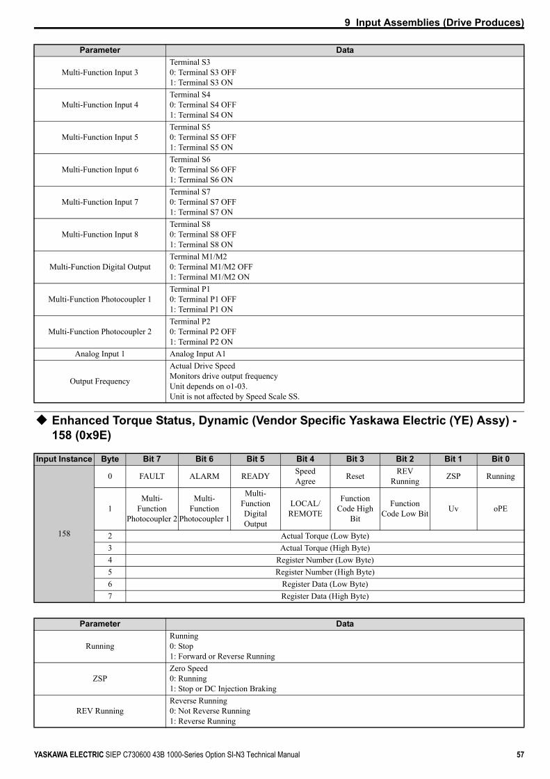
9 Input Assemblies (Drive Produces)
YASKAWA ELECTRIC SIEP C730600 43B 1000-Series Option SI-N3 Technical Manual 57
Enhanced Torque Status, Dynamic (Vendor Specific Yaskawa Electric (YE) Assy) - 158 (0x9E)
Multi-Function Input 3Terminal S30: Terminal S3 OFF1: Terminal S3 ON
Multi-Function Input 4Terminal S40: Terminal S4 OFF1: Terminal S4 ON
Multi-Function Input 5Terminal S50: Terminal S5 OFF1: Terminal S5 ON
Multi-Function Input 6Terminal S60: Terminal S6 OFF1: Terminal S6 ON
Multi-Function Input 7Terminal S70: Terminal S7 OFF1: Terminal S7 ON
Multi-Function Input 8Terminal S80: Terminal S8 OFF1: Terminal S8 ON
Multi-Function Digital OutputTerminal M1/M20: Terminal M1/M2 OFF1: Terminal M1/M2 ON
Multi-Function Photocoupler 1Terminal P10: Terminal P1 OFF1: Terminal P1 ON
Multi-Function Photocoupler 2Terminal P20: Terminal P2 OFF1: Terminal P2 ON
Analog Input 1 Analog Input A1
Output Frequency
Actual Drive SpeedMonitors drive output frequencyUnit depends on o1-03.Unit is not affected by Speed Scale SS.
Input Instance Byte Bit 7 Bit 6 Bit 5 Bit 4 Bit 3 Bit 2 Bit 1 Bit 0
158
0 FAULT ALARM READY SpeedAgree Reset REV
Running ZSP Running
1Multi-
FunctionPhotocoupler 2
Multi-Function
Photocoupler 1
Multi-Function Digital Output
LOCAL/REMOTE
Function Code High
Bit
Function Code Low Bit Uv oPE
2 Actual Torque (Low Byte)3 Actual Torque (High Byte)4 Register Number (Low Byte)5 Register Number (High Byte)6 Register Data (Low Byte)7 Register Data (High Byte)
Parameter Data
RunningRunning0: Stop1: Forward or Reverse Running
ZSPZero Speed0: Running1: Stop or DC Injection Braking
REV RunningReverse Running0: Not Reverse Running1: Reverse Running
Parameter Data
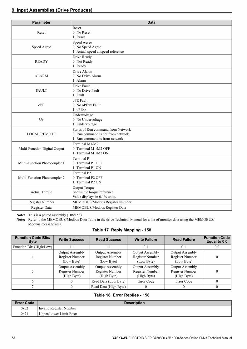
9 Input Assemblies (Drive Produces)
58 YASKAWA ELECTRIC SIEP C730600 43B 1000-Series Option SI-N3 Technical Manual
Note: This is a paired assembly (108/158).Note: Refer to the MEMOBUS/Modbus Data Table in the drive Technical Manual for a list of monitor data using the MEMOBUS/
Modbus message area.Table 17 Reply Mapping - 158
Table 18 Error Replies - 158
ResetReset0: No Reset1: Reset
Speed AgreeSpeed Agree0: No Speed Agree1: Actual speed at speed reference
READYDrive Ready0: Not Ready1: Ready
ALARMDrive Alarm0: No Drive Alarm1: Alarm
FAULTDrive Fault0: No Drive Fault1: Fault
oPEoPE Fault0: No oPExx Fault1: oPExx
UvUndervoltage0: No Undervoltage1: Undervoltage
LOCAL/REMOTEStatus of Run command from Network0: Run command is not from network1: Run command is from network
Multi-Function Digital OutputTerminal M1/M20: Terminal M1/M2 OFF1: Terminal M1/M2 ON
Multi-Function Photocoupler 1Terminal P10: Terminal P1 OFF1: Terminal P1 ON
Multi-Function Photocoupler 2Terminal P20: Terminal P2 OFF1: Terminal P2 ON
Actual TorqueOutput TorqueShows the torque reference.Value displays in 0.1% units.
Register Number MEMOBUS/Modbus Register NumberRegister Data MEMOBUS/Modbus Register Data
Function Code Bits/Byte Write Success Read Success Write Failure Read Failure Function Code
Equal to 0 0Function Bits (High/Low) 1 1 1 1 0 1 0 1 0 0
4Output Assembly Register Number
(Low Byte)
Output Assembly Register Number
(Low Byte)
Output Assembly Register Number
(Low Byte)
Output Assembly Register Number
(Low Byte)0
5Output Assembly Register Number
(High Byte)
Output Assembly Register Number
(High Byte)
Output Assembly Register Number
(High Byte)
Output Assembly Register Number
(High Byte)0
6 0 Read Data (Low Byte) Error Code Error Code 07 0 Read Data (High Byte) 0 0 0
Error Code Description0x02 Invalid Register Number0x21 Upper/Lower Limit Error
Parameter Data

9 Input Assemblies (Drive Produces)
YASKAWA ELECTRIC SIEP C730600 43B 1000-Series Option SI-N3 Technical Manual 59
Change of State Response (Vendor Specific Yaskawa Electric (YE) Assy) - 199 (0xC7)
0x22
Option generated busy event. The MEMOBUS/Modbus requested operation is in the process loop but the drive is not done yet.Writing “Enter” when drive is running.Attempt to write data that is read only.Attempt to write a constant when drive is running.During a CPF06 event attempting to write to registers other than A1-00 to A1-05, E1-03, o2-04.
0x23 Attempting to write during a drive undervoltage (Uv) event.0x24 Attempting to write while the drive is storing data.
Input Instance Byte Bit 7 Bit 6 Bit 5 Bit 4 Bit 3 Bit 2 Bit 1 Bit 0
199
0Multi-
Function Input 4
Multi-Function Input 3 NetCtrl NetRef Fault Reset External
Fault Run Rev Run Fwd
1 – – – –Multi-
Function Input 8
Multi-Function Input 7
Multi-Function Input 6
Multi-Function Input 5
2 FAULT ALARM READY Speed Agree Reset REV Running ZSP Running
3 NetCtrl(Status)
NetRef(Status) – – – 2nd Motor Uv oPE
4 Output Frequency (Low Byte)5 Output Frequency (High Byte)6 Actual Torque (Low Byte)7 Actual Torque (High Byte)
Parameter Data
Run FwdForward Run command from Network0: Forward Run command is not from network1: Forward Run command is from network
Run RevReverse Run command from Network0: Reverse Run command is not from network1: Reverse Run command is from network
External FaultExternal Fault command from Network0: External Fault command is not from network1: External Fault command is from network
Fault ResetFault Reset command from Network0: Fault Reset command is not from network1: Fault Reset command is from network
NetRefReference command from Network0: Reference command is not from network1: Reference command is from network
NetCtrlRun command from Network0: Run command is not from network1: Run command is from network
Multi-Function Input 3Terminal S3 command by Network0: Terminal S3 command OFF1: Terminal S3 command ON
Multi-Function Input 4Terminal S4 command by Network0: Terminal S4 command OFF1: Terminal S4 command ON
Multi-Function Input 5Terminal S5 command by Network0: Terminal S5 command OFF1: Terminal S5 command ON
Multi-Function Input 6Terminal S6 command by Network0: Terminal S6 command OFF1: Terminal S6 command ON
Error Code Description

9 Input Assemblies (Drive Produces)
60 YASKAWA ELECTRIC SIEP C730600 43B 1000-Series Option SI-N3 Technical Manual
Multi-Function Input 7Terminal S7 command by Network0: Terminal S7 command OFF1: Terminal S7 command ON
Multi-Function Input 8Terminal S8 command by Network0: Terminal S8 command OFF1: Terminal S8 command ON
RunningRunning0: Stop1: Forward or Reverse Running
ZSPZero Speed0: Running1: Stop or DC Injection Braking
REV RunningReverse Running0: Not Reverse Running1: Reverse Running
ResetReset0: No Reset1: Reset
Speed AgreeSpeed Agree0: No Speed Agree1: Actual speed at speed reference
READYDrive Ready0: Not Ready1: Ready
ALARMDrive Alarm0: No Drive Alarm1: Alarm
FAULTDrive Fault0: No Drive Fault1: Fault
oPEoPE Fault0: No oPExx fault1: oPExx
UvUndervoltage0: No Undervoltage1: Undervoltage
2nd MotorStatus of Second Motor0: First Motor Select1: Second Motor Select
NetRef (Status)Status of reference command from Network0: Reference command is not from network1: Reference command is from network
NetCtrl (Status)Status of Run command from Network0: Run command is not from network1: Run command is from network
Output Frequency
Actual Drive SpeedMonitors drive output frequencyUnit depends on o1-03.Unit is not affected by Speed Scale SS.
Actual TorqueOutput Torque Shows the torque reference.Value displays in 0.1% units.
Parameter Data

10 General Class Objects
YASKAWA ELECTRIC SIEP C730600 43B 1000-Series Option SI-N3 Technical Manual 61
10 General Class Objects
Identity Object - 1 (Class 0x01)
Services Supported
Attributes Supported
Message Router Object - 2 (Class 0x02)
Services Supported
Attributes Supported
DeviceNet Object - 3 (Class 0x03)
Services Supported
Service Code No. (hex) Service Name0E Get Attribute Single10 Set Attribute Single05 Reset
Instance ID Attribute Name Description Get Set Size Range Default
0 1 Object Software Revision The Identity Object software revision – Word – 1
1 1 Vendor ID Manufacturer code.44 (2C Hex): Yaskawa Electric – Word – 44 (YASKAWA)
1 2 Device Type
The device profile.The profile for this product is an AC drive.2: AC drive
– Word – 2 (AC Drives)
1 3 Product Code Product codes determined by the manufacturer. – Word – <1>
<1> Product code is 2 bytes. The first byte is the drive type and the second byte is the model number of the drive.
1 4 Revision Software revision for the option card. – Word – Depends on software1 5 Status The comm. status for the drive. – Word – 01 6 Serial Number Option card serial number – Long – Each unit is unique
1 7 Product Name Product name. –String
(14 Bytes)
– Product-dependentex: CIMR-AA2A0004
1 8 StateThe operation status of the drive.3: Drive ready4: Fault
– Byte – 3
1 9 Configuration Consistency Value
Shows verification data for any parameters that have been edited from their default values.
– Word – 0000
1 10 Heartbeat Interval Heartbeat interval. Word 0 to 10 0=disabled
Service Code No. (hex) Service Name0E Get Attribute Single
Instance ID Attribute Name Description Get Set Size Default
0 1 Object Software Revision The Message Router object software revision – Word 1
Service Code No. (hex) Service Name0E Get Attribute Single

10 General Class Objects
62 YASKAWA ELECTRIC SIEP C730600 43B 1000-Series Option SI-N3 Technical Manual
Attributes Supported
Assembly Object - 4 (Class 0x04)
Services Supported
Attributes Supported
10 Set Attribute Single05 Reset
Instance ID Attribute Name Description Get Set Size Range Default
(Hex)
0 1 Object Software Revision
The DeviceNet object software revision. – Word – 2
1 1 MAC ID Current Value of MAC Address <1>
<1> Set only settable when Attribute 08, F6-50 = 64<2> Set only valid when Attribute 09, F6-51 = 3.
Byte 0 to 63 631 2 Baud Rate Current Value of Baud Rate <2> Byte 0 to 3 00
1 3 Bus Off Interruption (BOI)
Operation at a Bus off Detection is shown. – Byte 00, 01 00
1 4 Bus Off Counter The number of Bus off Detection is shown – Byte 0 to 255 00
1 5 Allocation Information The DeviceNet communication connection information. – Byte x2 – 00, 00
1 6 MAC ID Switch Changed
Indication that MAC Address Switch Changed since last Power-up – Bool – 0
1 7 Baud Rate Switch Changed
Indication that Baud Rate Switch Changed since last Power-up – Bool – 0
1 8 MAC ID Switch Value The MAC ID setting value.Setting through drive operator, F6-50. – Byte 0 to 64 –
1 9 Baud Rate Switch Value
The Baud rate setting value.Setting through drive operator. – Byte 0 to 4 –
Service Code No. (hex) Service Name0E Get Attribute Single10 Set Attribute Single
Instance ID Attribute Name Description Get Set Size Default
0 1 Object Software Revision The DeviceNet Object software revision – Word 2
20 3 Data Same function as the Basic Speed Control (Output Assembly)
Array 4 bytes 00 00 00 00
21 3 Data Same function as the Extended Speed Control (Output Assembly)
Array 4 bytes 00 00 00 00
22 3 Data Same function as the Speed and Torque Control (Output Assembly)
Array 6 Bytes 00 00 00 00 00 00
23 3 Data Same function as the Extended Speed and Torque Control (Output Assembly)
Array 6 Bytes 00 00 00 00 00 00
70 3 Data Same function as the Basic Speed Control (Input Assembly) – Array 4
bytes 00 00 00 00
71 3 Data Same function as the Extended Speed Control (Input Assembly) – Array 4
bytes 00 00 00 00
72 3 Data Same function as the Speed Control (Input Assembly) – Array 6
bytes 00 00 00 00 00 00
73 3 Data Same function as the Speed and Torque Control (Input Assembly) – Array 6
bytes 00 00 00 00 00 00
100 3 Data Same function as the MEMOBUS/Modbus Message Command (Output Assembly)
Array 5 bytes 00 00 00 00 00
Service Code No. (hex) Service Name

10 General Class Objects
YASKAWA ELECTRIC SIEP C730600 43B 1000-Series Option SI-N3 Technical Manual 63
101 3 Data Same function as the Standard Control (Output Assembly)
Array 8 bytes 00 00 00 00 00 00 00 00
102 3 Data Same function as the Accel/ Decel Time (Output Assembly)
Array 8 bytes 00 00 00 00 00 00 00 00
105 3 Data Same function as the Enhanced Torque Control, Dynamic (Output Assembly)
Array 8 bytes 00 00 00 00 00 00 00 00
106 3 Data Same function as the Enhanced Control (Output Assembly)
Array 8 bytes 00 00 00 00 00 00 00 00
107 3 Data Same function as the Standard DI/DO Control (Output Assembly)
Array 8 bytes 00 00 00 00 00 00 00 00
108 3 Data Same function as the Enhanced Torque Control, Dynamic (Output Assembly)
Array 8 bytes 00 00 00 00 00 00 00 00
120 3 Data Same function as the Speed Command 1 (Output Assembly)
Array 4 bytes 00 00 00 00
121 3 Data Same function as the Torque Command 1 (Output Assembly)
Array 4 bytes 00 00 00 00
122 3 Data Same function as the Speed Command 2(Output Assembly)
Array 6 bytes 00 00 00 00 00 00
123 3 Data Same function as the Torque Command 2 (Output Assembly)
Array 6 bytes 00 00 00 00 00 00
124 3 Data Same function as the Speed Dynamic Assy (Output Assembly)
Array 8 bytes 00 00 00 00 00 00 00 00
125 3 Data Same function as the Torque Dynamic Assy (Output Assembly)
Array 8 bytes 00 00 00 00 00 00 00 00
126 3 Data Same function as the Speed / Torque Assy (Output Assembly)
Array 8 bytes 00 00 00 00 00 00 00 00
130 3 Data Same function as the Speed Status 1 (Input Assembly) – Array 4
bytes 00 00 00 00
131 3 Data Same function as the Current Status 1 (Input Assembly) – Array 4
bytes 00 00 00 00
132 3 Data Same function as the Current & Speed Status 1 (Input Assembly) – Array 6
bytes 00 00 00 00 00 00
134 3 Data Same function as the Speed Status Dynamic Assy (Input Assembly) – Array 8
bytes 00 00 00 00 00 00 00 00
135 3 Data Same function as the Current Status Dynamic Assy (Input Assembly) – Array 8
bytes 00 00 00 00 00 00 00 00
136 3 Data Same function as the Torque and Speed Status (Input Assembly) – Array 8
bytes 00 00 00 00 00 00 00 00
150 3 Data Same function as the MEMOBUS/Modbus Message Reply (Input Assembly) – Array 5
bytes 00 00 00 00 00
151 3 Data Same function as the Standard Status (Input Assembly) – Array 8
bytes 00 00 00 00 00 00 00 00
152 3 Data Same function as the Standard Status 2 (Input Assembly) – Array 8
bytes 00 00 00 00 00 00 00 00
155 3 Data Same function as the Enhanced Speed Status (Input Assembly) – Array 8
bytes 00 00 00 00 00 00 00 00
156 3 Data Same function as the Enhanced Control Status (Input Assembly) – Array 8
bytes 00 00 00 00 00 00 00 00
157 3 Data Same function as the Standard DI/DO Status (Input Assembly) – Array 8
bytes 00 00 00 00 00 00 00 00
158 3 Data Same function as the Enhanced Torque Status, Dynamic (Input Assembly) – Array 8
bytes 00 00 00 00 00 00 00 00
199 3 Data Same function as the Change of State Response (Input Assembly) – Array 8
bytes 00 00 00 00 00 00 00 00
Instance ID Attribute Name Description Get Set Size Default
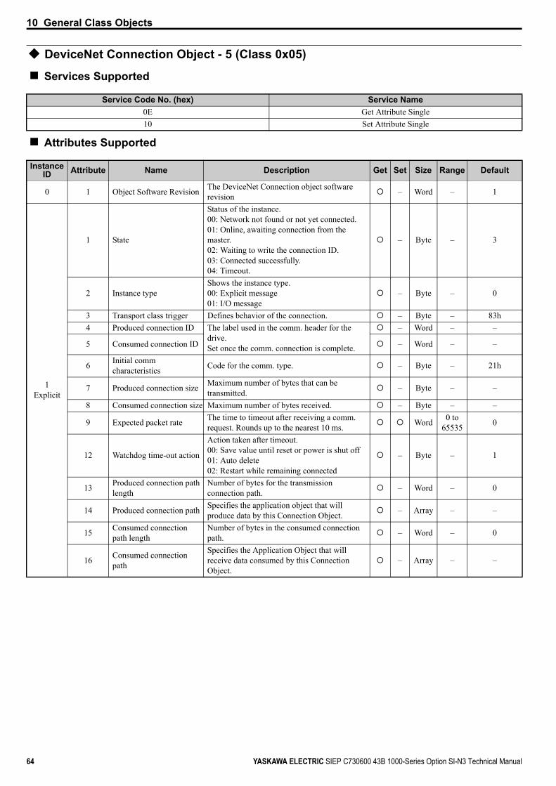
10 General Class Objects
64 YASKAWA ELECTRIC SIEP C730600 43B 1000-Series Option SI-N3 Technical Manual
DeviceNet Connection Object - 5 (Class 0x05)
Services Supported
Attributes Supported
Service Code No. (hex) Service Name0E Get Attribute Single10 Set Attribute Single
Instance ID Attribute Name Description Get Set Size Range Default
0 1 Object Software Revision The DeviceNet Connection object software revision – Word – 1
1Explicit
1 State
Status of the instance.00: Network not found or not yet connected.01: Online, awaiting connection from the master.02: Waiting to write the connection ID.03: Connected successfully.04: Timeout.
– Byte – 3
2 Instance typeShows the instance type.00: Explicit message01: I/O message
– Byte – 0
3 Transport class trigger Defines behavior of the connection. – Byte – 83h4 Produced connection ID The label used in the comm. header for the
drive.Set once the comm. connection is complete.
– Word – –
5 Consumed connection ID – Word – –
6 Initial comm characteristics Code for the comm. type. – Byte – 21h
7 Produced connection size Maximum number of bytes that can be transmitted. – Byte – –
8 Consumed connection size Maximum number of bytes received. – Byte – –
9 Expected packet rate The time to timeout after receiving a comm. request. Rounds up to the nearest 10 ms. Word 0 to
65535 0
12 Watchdog time-out action
Action taken after timeout.00: Save value until reset or power is shut off01: Auto delete02: Restart while remaining connected
– Byte – 1
13 Produced connection path length
Number of bytes for the transmission connection path. – Word – 0
14 Produced connection path Specifies the application object that will produce data by this Connection Object. – Array – –
15 Consumed connection path length
Number of bytes in the consumed connection path. – Word – 0
16 Consumed connection path
Specifies the Application Object that will receive data consumed by this Connection Object.
– Array – –
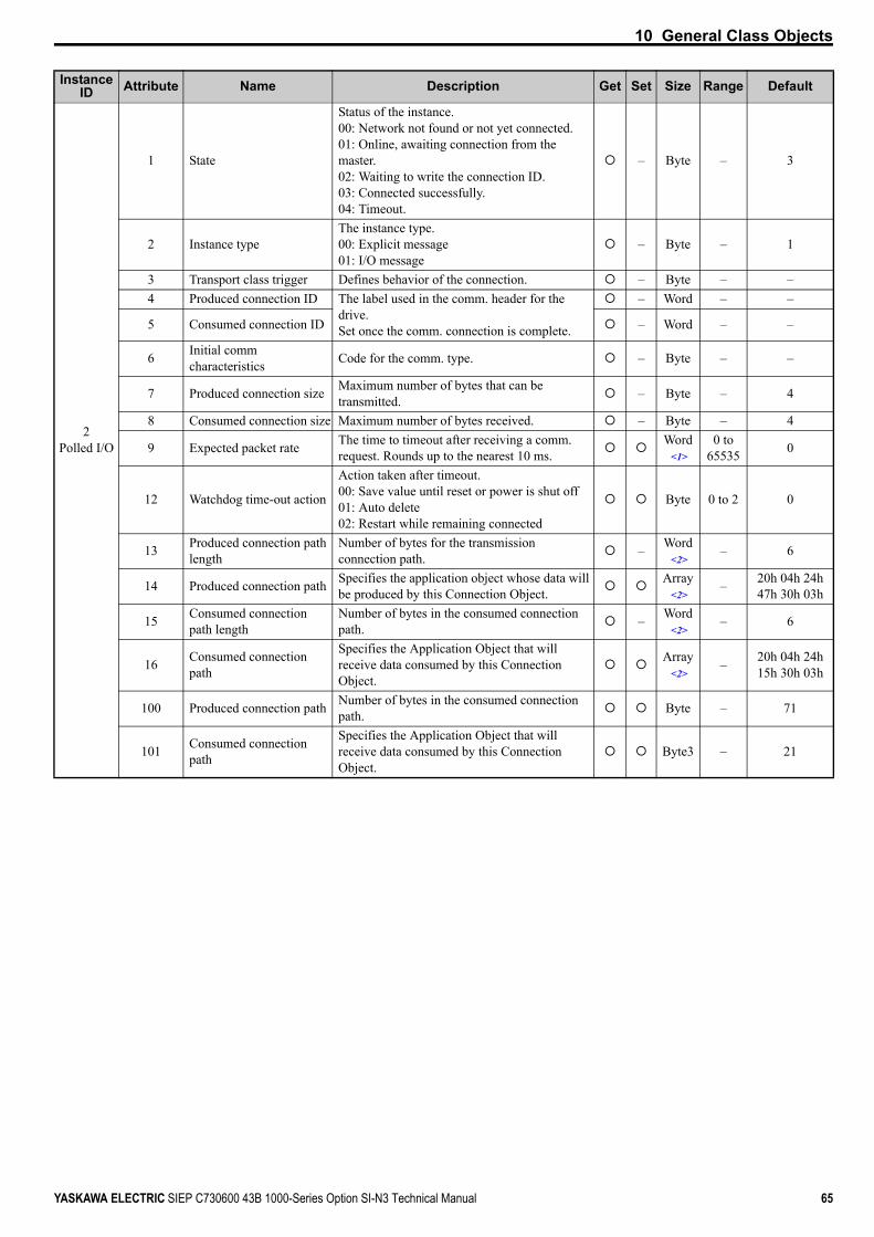
10 General Class Objects
YASKAWA ELECTRIC SIEP C730600 43B 1000-Series Option SI-N3 Technical Manual 65
2Polled I/O
1 State
Status of the instance.00: Network not found or not yet connected.01: Online, awaiting connection from the master.02: Waiting to write the connection ID.03: Connected successfully.04: Timeout.
– Byte – 3
2 Instance typeThe instance type.00: Explicit message01: I/O message
– Byte – 1
3 Transport class trigger Defines behavior of the connection. – Byte – –4 Produced connection ID The label used in the comm. header for the
drive.Set once the comm. connection is complete.
– Word – –
5 Consumed connection ID – Word – –
6 Initial comm characteristics Code for the comm. type. – Byte – –
7 Produced connection size Maximum number of bytes that can be transmitted. – Byte – 4
8 Consumed connection size Maximum number of bytes received. – Byte – 4
9 Expected packet rate The time to timeout after receiving a comm. request. Rounds up to the nearest 10 ms.
Word<1>
0 to 65535 0
12 Watchdog time-out action
Action taken after timeout.00: Save value until reset or power is shut off01: Auto delete02: Restart while remaining connected
Byte 0 to 2 0
13 Produced connection path length
Number of bytes for the transmission connection path. – Word
<2>– 6
14 Produced connection path Specifies the application object whose data will be produced by this Connection Object.
Array<2>
– 20h 04h 24h 47h 30h 03h
15 Consumed connection path length
Number of bytes in the consumed connection path. – Word
<2>– 6
16 Consumed connection path
Specifies the Application Object that will receive data consumed by this Connection Object.
Array<2>
– 20h 04h 24h 15h 30h 03h
100 Produced connection path Number of bytes in the consumed connection path. Byte – 71
101 Consumed connection path
Specifies the Application Object that will receive data consumed by this Connection Object.
Byte3 – 21
Instance ID Attribute Name Description Get Set Size Range Default
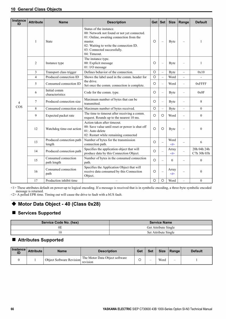
10 General Class Objects
66 YASKAWA ELECTRIC SIEP C730600 43B 1000-Series Option SI-N3 Technical Manual
Motor Data Object - 40 (Class 0x28)
Services Supported
Attributes Supported
4COS
1 State
Status of the instance.00: Network not found or not yet connected.01: Online, awaiting connection from the master.02: Waiting to write the connection ID.03: Connected successfully.04: Timeout.
– Byte – 1
2 Instance typeThe instance type.00: Explicit message01: I/O message
– Byte – 1
3 Transport class trigger Defines behavior of the connection. – Byte – 0x104 Produced connection ID Shows the label used in the comm. header for
the drive.Set once the comm. connection is complete.
– Word – -
5 Consumed connection ID – Word – 0xFFFF
6 Initial comm characteristics Code for the comm. type. – Byte – 0x0F
7 Produced connection size Maximum number of bytes that can be transmitted. – Byte – 8
8 Consumed connection size Maximum number of bytes received. – Byte – 0
9 Expected packet rate The time to timeout after receiving a comm. request. Rounds up to the nearest 10 ms. Word – 0
12 Watchdog time-out action
Action taken after timeout.00: Save value until reset or power is shut off01: Auto delete02: Restart while remaining connected
Byte – 0
13 Produced connection path length
Number of bytes for the transmission connection path. – Word
<1>– 6
14 Produced connection path Specifies the application object that will produce data by this Connection Object. – Array
<1>– 20h 04h 24h
C7h 30h 03h
15 Consumed connection path length
Number of bytes in the consumed connection path. – 0 – 0
16 Consumed connection path
Specifies the Application Object that will receive data consumed by this Connection Object.
– Array<1>
– 0
17 Production inhibit time – Word – 0
<1> These attributes default on power-up to logical encoding. If a message is received that is in symbolic encoding, a three-byte symbolic encoded message is returned.
<2> A polled EPR time. Timing out will cause the drive to fault with a bUS fault.
Service Code No. (hex) Service Name0E Get Attribute Single10 Set Attribute Single
Instance ID Attribute Name Description Get Set Size Range Default
0 1 Object Software Revision The Motor Data Object software revision – Word – 1
Instance ID Attribute Name Description Get Set Size Range Default
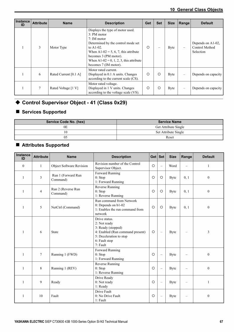
10 General Class Objects
YASKAWA ELECTRIC SIEP C730600 43B 1000-Series Option SI-N3 Technical Manual 67
Control Supervisor Object - 41 (Class 0x29)
Services Supported
Attributes Supported
1 3 Motor Type
Displays the type of motor used.3: PM motor7: IM motorDetermined by the control mode set to A1-02.When A1-02 = 5, 6, 7, this attribute becomes 3 (PM motor).When A1-02 = 0, 1, 2, 3, this attribute becomes 7 (IM motor).
– Byte –Depends on A1-02, Control Method Selection
1 6 Rated Current [0.1 A]Motor rated current.Displayed in 0.1 A units. Changes according to the current scale (CS).
Byte – Depends on capacity
1 7 Rated Voltage [1 V]Motor rated voltage.Displayed in 1 V units. Changes according to the voltage scale (VS).
Byte – Depends on capacity
Service Code No. (hex) Service Name0E Get Attribute Single10 Set Attribute Single05 Reset
Instance ID Attribute Name Description Get Set Size Range Default
0 1 Object Software Revision Revision number of the Control Supervisor Object. – Word – 1
1 3 Run 1 (Forward Run Command)
Forward Running 0: Stop1: Forward Running
Byte 0, 1 0
1 4 Run 2 (Reverse Run Command)
Reverse Running 0: Stop1: Reverse Running
Byte 0, 1 0
1 5 NetCtrl (Command)
Run command from Network0: Depends on b1-021: Enables the run command from network
Byte 0, 1 0
1 6 State
Drive status.2: Not ready3: Ready (stopped)4: Enabled (Run command present)5: Deceleration to stop6: Fault stop7: Fault
– Byte – 3
1 7 Running 1 (FWD)Forward Running 0: Stop1: Forward Running
– Byte – 0
1 8 Running 1 (REV)Reverse Running 0: Stop1: Reverse Running
– Byte – 0
1 9 ReadyDrive Ready0: Not ready1: Ready
– Byte – 1
1 10 FaultDrive Fault0: No Drive Fault1: Fault
– Byte – 0
Instance ID Attribute Name Description Get Set Size Range Default

10 General Class Objects
68 YASKAWA ELECTRIC SIEP C730600 43B 1000-Series Option SI-N3 Technical Manual
DeviceNet Fault Code Conversion Table
1 11 WarningWarning0: No Warning1: Warning
– Byte – 0
1 12 Fault ResetFault Reset 0: No Fault Reset 1: Fault Reset
Byte 0, 1 0
1 13 Fault Code
Current Fault Refer to DeviceNet Fault Code Conversion Table on page 68 for details
– Word – 0000
1 15 Control from Net (Status)
Run Command from DeviceNet0: Enables the run command from except for DeviceNet1: Enables the run command from DeviceNet
– Byte – 0
1 16 DeviceNet Fault Mode Normal 2 (vendor specific) – Byte – 2
1 17 Force Fault
External fault0: No External Fault1: External fault (EF0)Triggered by the rising edge of the signal
Byte 0, 1 0
1 18 Force Reset
External fault status0: No External Fault1: External faultTriggered by the rising edge of the signal.
– Byte – 0
Drive Fault Code [Dec] (MEMOBUS/Modbus #0080hex) DeviceNet Fault Code [hex] Description
0 0000 None2 3220 DC Bus Undervoltage (Uv1)3 5110 CTL PS Undervoltage (Uv2)4 3222 MC Answerback (Uv3)6 2120 Ground Fault (GF)7 2300 Over Current (oC)8 3210 DC Bus Overvoltage (ov)9 4200 Heatsink Overtemp (oH)10 4210 Heatsink Max Temp (oH1)11 2220 Motor Overload (oL1)12 2200 Inv Overload (oL2)13 2221 Overtorque Det 1 (oL3)14 2222 Overtorque Det 2 (oL4)15 7110 DynBrk Transistor (rr)16 7112 DynBrk Resistor (rH)17 9000 External Fault 3 (EF3)18 9000 External Fault 4 (EF4)19 9000 External Fault 5 (EF5)20 9000 External Fault 6 (EF6)21 9000 External Fault 7 (EF7)22 9000 External Fault 8 (EF8)24 7310 Overspeed Det (oS)25 7310 Speed Deviation (dEv)26 7301 PG Open (PGo)27 3130 Input Phase Loss (PF)28 3130 Output Phase Loss (LF)29 5210 Motor Overheat 1 (PTC input) (oH3)
Instance ID Attribute Name Description Get Set Size Range Default
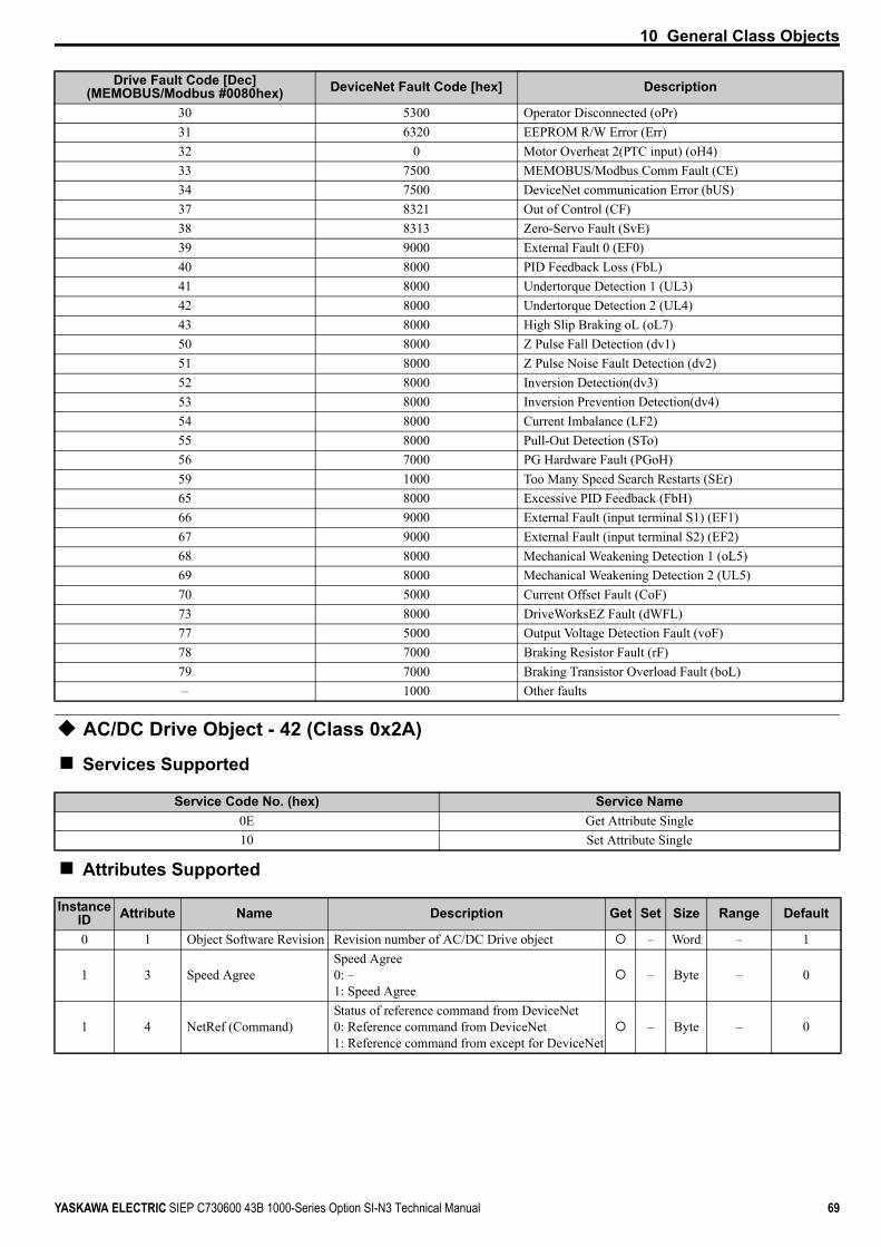
10 General Class Objects
YASKAWA ELECTRIC SIEP C730600 43B 1000-Series Option SI-N3 Technical Manual 69
AC/DC Drive Object - 42 (Class 0x2A)
Services Supported
Attributes Supported
30 5300 Operator Disconnected (oPr)31 6320 EEPROM R/W Error (Err)32 0 Motor Overheat 2(PTC input) (oH4)33 7500 MEMOBUS/Modbus Comm Fault (CE)34 7500 DeviceNet communication Error (bUS)37 8321 Out of Control (CF)38 8313 Zero-Servo Fault (SvE)39 9000 External Fault 0 (EF0)40 8000 PID Feedback Loss (FbL)41 8000 Undertorque Detection 1 (UL3)42 8000 Undertorque Detection 2 (UL4)43 8000 High Slip Braking oL (oL7)50 8000 Z Pulse Fall Detection (dv1)51 8000 Z Pulse Noise Fault Detection (dv2)52 8000 Inversion Detection(dv3)53 8000 Inversion Prevention Detection(dv4)54 8000 Current Imbalance (LF2)55 8000 Pull-Out Detection (STo)56 7000 PG Hardware Fault (PGoH)59 1000 Too Many Speed Search Restarts (SEr)65 8000 Excessive PID Feedback (FbH)66 9000 External Fault (input terminal S1) (EF1)67 9000 External Fault (input terminal S2) (EF2)68 8000 Mechanical Weakening Detection 1 (oL5)69 8000 Mechanical Weakening Detection 2 (UL5)70 5000 Current Offset Fault (CoF)73 8000 DriveWorksEZ Fault (dWFL)77 5000 Output Voltage Detection Fault (voF)78 7000 Braking Resistor Fault (rF)79 7000 Braking Transistor Overload Fault (boL)– 1000 Other faults
Service Code No. (hex) Service Name0E Get Attribute Single10 Set Attribute Single
Instance ID Attribute Name Description Get Set Size Range Default
0 1 Object Software Revision Revision number of AC/DC Drive object – Word – 1
1 3 Speed AgreeSpeed Agree 0: –1: Speed Agree
– Byte – 0
1 4 NetRef (Command)Status of reference command from DeviceNet0: Reference command from DeviceNet1: Reference command from except for DeviceNet
– Byte – 0
Drive Fault Code [Dec] (MEMOBUS/Modbus #0080hex) DeviceNet Fault Code [hex] Description

10 General Class Objects
70 YASKAWA ELECTRIC SIEP C730600 43B 1000-Series Option SI-N3 Technical Manual
1 6 Drive Mode
Drive control mode.0: OLV0: OLV for PM motors (Read only)0: Advanced OLV for PM motors (Read only)1: V/f control2: V/f control with PG3: CLV3: CLV for PM motors (Read only)
Byte 0 to 3 0
1 7 Speed Actual Actual Drive Speed Unit is not affected by Speed Scale SS. – Word – 3
1 8 Speed ReferenceFrequency ReferenceMonitors drive frequency reference.Unit is not affected by Speed Scale SS.
Word – 0
1 9 Current Actual
Actual Output CurrentMonitors drive output currentUnit is 0.1 AUnit is not affected by Current Scale CS.
– Word – 0
1 11 Torque Actual Drive Output Torque Unit is affected by Torque Scale TS – Word – 0
1 12 Torque Reference/Torque Limit
Torque Reference/Torque LimitSets the torque reference and torque limit. The units are determined by the torque scale.Sets the torque reference when using torque control (d5-01 = 1).Sets the torque limit when using speed control (d5-01 = 0).The torque reference and torque limit are disabled when F6-06 = 0.
Word – 0
1 15 Power Actual [W] Drive Output Power Unit is affected by Power Scale PS – Word – 0
1 16 Input Voltage [V] Drive Input VoltageUnit is affected by Voltage Scale VS – Word – Depends on
capacity
1 17 Output Voltage [V] Drive Output VoltageUnit is affected by Voltage Scale VS – Word – 0
1 18 Accel Time [ms]Acceleration Time 1 (C1-01)Units set in parameter C1-10.Unit is affected by Time scale (TS).
Word – 2710 h
1 19 Decel Time [ms]Deceleration Time 1 (C1-02)Units set in parameter C1-10.Unit is affected by Time scale (TS).
Word – 2710 h
1 20 Low Speed Limit Percent of Max Speed Frequency Reference Lower Limit (d2-02) Word 0 to 1100 0
1 21 High Speed Limit Percent of Max Speed Frequency Reference Upper Limit (d2-01) Word 0 to 1100 3E8h
1 22 Speed Scale (–15 to 15) Setting for F6-56, scale of units for speed-related data Byte –15 to 15 0
1 23 Current Scale (–15 to 15) Setting for F6-57, scale of units for current-related data Byte –15 to 15 0
1 24 Torque Scale (–15 to 15) Setting for F6-58, scale of units for torque-related data Byte –15 to 15 0
1 26 Power Scale (–15 to 15) Setting for F6-59, scale of units for power-related data Byte –15 to 15 0
1 27 Voltage Scale (–15 to 15) Setting for F6-60, scale of units for voltage-related data Byte –15 to 15 0
1 28 Time Scale (–15 to 15) Setting for F6-61, scale of units for speed-related data Byte –15 to 15 0
1 29 Reference from Net (Status)
Status of reference command from DeviceNet0: Reference command from DeviceNet1: Reference command from except for DeviceNet
– Byte – 0
Instance ID Attribute Name Description Get Set Size Range Default

11 Vendor-Specific (Yaskawa) Class Objects
YASKAWA ELECTRIC SIEP C730600 43B 1000-Series Option SI-N3 Technical Manual 71
11 Vendor-Specific (Yaskawa) Class Objects
Yaskawa Drive Parameters Object - 100 (Class 0x64)
Services Supported
This is a dynamic explicit Class Object. With this Class object any drive parameter with a MEMOBUS/Modbus address greater than 0x00FF can be accessed. The mapping of Class Object instance / attribute to MEMOBUS/Modbus address is as follows.
Given a typical MEMOBUS/Modbus Address of 0xXXYY
The DeviceNet Instance value is equal to XX
The DeviceNet Attribute value is equal to YY
As an example, to access parameter b5-12 (MEMOBUS/Modbus Address = 0x01B0)
Class Object is 100 (0x64) (Always for this Class Object)
Instance = 0x01
Attribute = 0xB0Note: Writing a zero to 0x0900 (Enter) stores changed parameters to the drive non-volatile memory. Writing a zero to 0x0910 (Accept)
allows the drive to use the changed parameters. This normally is automatically sent when the parameter is changed. Read Enter Command 0x0900 or Accept Command 910 will always return a value of 0x0001.
Attributes Supported
Note: Attempting to set a read-only parameter results in a DeviceNet error code of 0x0E, Attribute Not Settable.Note: Attempting to access an invalid parameter results in a DeviceNet error code of 0x09, Invalid Attribute ValueNote: Refer to the MEMOBUS/Modbus Data Table in the drive Technical Manual or a list of monitor data using the MEMOBUS/
Modbus message area.
Service Code No. (hex) Service Name0E Get Attribute Single10 Set Attribute Single
Instance ID Attribute Name Description Get Set Size Range Default
0 1 Object Software Revision The Yaskawa drive parameters object software revision – Word – 1
1 00 MEMOBUS/Modbus Register 0x0100 Language selection Word 0 to 7 1
1 01 MEMOBUS/Modbus Register 0x0101 Parameter access level Word 0 to 2 2
1 YY MEMOBUS/Modbus Registers 0x0100 ~ 0x01FF
MEMOBUS/Modbus registers 0x0100 to 0x01FF Word – –
2 YY MEMOBUS/Modbus Registers 0x0200 ~ 0x02FF
MEMOBUS/Modbus registers 0x0200 to 0x02FF Word – –
.. .. .. .. Word – –
255 YY MEMOBUS/Modbus Register 0xFF00 ~ 0xFFFF
MEMOBUS/Modbus registers 0xFF00 to 0xFFFF Word – –

11 Vendor-Specific (Yaskawa) Class Objects
72 YASKAWA ELECTRIC SIEP C730600 43B 1000-Series Option SI-N3 Technical Manual
Yaskawa Monitor/Control Object - 125 (Class 0x7D)
Services Supported
This is a dynamic explicit Class Object. Any parameter with a MEMOBUS/Modbus address lower than 0x0100 can be accessed with this class object. This class is similar to the Drive Parameters Object Class 100, except that since the most significant byte of MEMOBUS/Modbus address is always zero, the instance in this class remains at 1.
Given a typical MEMOBUS/Modbus Address 0f 0x00YY
The DeviceNet Instance value is equal to 0x01
The DeviceNet Attribute value is equal to YY
As an example, to access Drive Status (MEMOBUS/Modbus Address = 0x002C)
Class Object is 125 (0x7D) (Always for this Class Object)
Instance = 0x01
Attribute = 0x2C
Attributes Supported
Note: Attempting to set a read-only parameter results in a DeviceNet error code of 0x0E, Attribute Not Settable.Note: Attempting to access an invalid parameter results in a DeviceNet error code of 0x09, Invalid Attribute ValueNote: Refer to the MEMOBUS/Modbus Data Table in the drive Technical Manual or a list of monitor data using the MEMOBUS/
Modbus message area.
Service Code No. (hex) Service Name0E Get Attribute Single10 Set Attribute Single
Instance ID Attribute MEMOBUS/Modbus Address Description Get Set Size
0 1 - Object Software Revision - Word1 1 0x0001 Drive Command Bits Word1 2 0x0002 Frequency Instruction Word.. .. .. .. Word1 255 0x00FF Unused Word

12 Troubleshooting
YASKAWA ELECTRIC SIEP C730600 43B 1000-Series Option SI-N3 Technical Manual 73
12 Troubleshooting
Drive-Side Error CodesTable 19 lists the various option-related fault codes. Refer to the drive Technical Manual for further information about fault codes.
FaultsBoth bUS (Option Communication Error) and EF0 (External Fault Input from the option) can appear as either an alarm or as a fault. When a fault occurs, the digital operator ALM LED remains lit. When an alarm occurs, the digital operator ALM LED flashes.
Check the following items first when an error code occurs on the drive:
• Communication cable connections• Make sure the option is properly installed to the drive• Operation status of the controller program and controller CPU• Did a momentary power loss interrupt communications?
Table 19 Fault Displays, Causes, and Possible Solutions
Digital Operator Display Fault Name
bUS
Option Communication ErrorThe connection was lost after establishing initial communication.Only detected when the run command frequency reference is assigned to the option (bl-01 = 3 or bl-02 = 3).
Cause Possible SolutionMaster controller (PLC) has stopped communicating Check for faulty wiring.
Correct any wiring problems.Communication cable is not connected properly
A data error occurred due to noise
• Counteract noise in the control circuit wiring, main circuit lines, and ground wiring.• If a magnetic contactor is the noise source, install a surge absorber to the contactor coil.• Use cables recommended by Yaskawa or another type of shielded line. Ground the shield on the controller side and on the option side.
Option is damaged If there are no wiring problems and the fault continues to occur, replace the option.
Network power loss The power on the DeviceNet network cable is 0. Verify power is available between option terminals V+ (red) and V- (black).
Connection timeout The option Expected Packet Rate (EPR) timer timed out.Make sure that EPR time is set properly.
Duplicate MAC ID The option MAC ID and at least one other node have the same MAC ID. Verify F6-50 is set properly.
Digital Operator Display Fault Name
EF0External Fault Input from the optionThe alarm function for an external device has been triggered.
Cause Possible SolutionAn external fault is being sent from the main controller (PLC)
• Remove the cause of the external fault• Reset the external fault input from the PLC device
Problem with the PLC program Check the program used by the PLC and make the appropriate corrections.Digital Operator Display Fault Name
oFA00Non-Compatible Option connected to drive port CN5-AOption is not properly connected.
Cause Possible SolutionNon-compatible option connected to drive port CN5-A
Use only compatible options. Connect the SI-N3 to CN5-A. For other option connections refer to the Installation Manual for those options.
Digital Operator Display Fault Name
oFA01Option Fault (CN5-A)Option is not properly connected.
Cause Possible SolutionProblem with the connector between the drive and option Turn the power off and check the connectors between the drive and option.

12 Troubleshooting
74 YASKAWA ELECTRIC SIEP C730600 43B 1000-Series Option SI-N3 Technical Manual
Minor Faults and Alarms
Explicit Message Communications ErrorsWhen there is a problem with a request message sent from the master in explicit communications, the drive will return a response message with a service code of “94” and an error code from Table 20 as the data.
Table 20 Explicit Message Error Codes, Causes, and Possible Solutions
Digital Operator Display Fault Name
to oFA30 to oFA43Option Fault (CN5-A)Communication ID error.
Cause Possible SolutionOption hardware fault Replace the option. Contact Yaskawa for assistance.
Digital Operator Display Fault Name
oFb00Non-Compatible Option connected to drive port CN5-BNon-compatible option is connected.
Cause Possible SolutionNon-compatible option connected to drive port CN5-B
Use only compatible options. Connect the SI-N3 to CN5-A. For other option connections refer to the Installation Manual for those options.
Digital Operator Display Fault Name
oFb02Option Fault (CN5-B)Two of the same option are connected simultaneously.
Cause Possible SolutionOptions AI-A3 or D1-A3 connected to the CN5-B port while an option was connected to CN5-A
Only one of these options, AI-A3, DI-A3 or SI- option can be connected to the drive at the same time. The SI-N3 must be connected to CN5-A.
Digital Operator Display Fault Name
oFc00Non-Compatible Option connected to drive port CN5-CNon-compatible option is connected.
Cause Possible Solution
Non-compatible option connected to port CN5-C Use only compatible options. Connect the SI-N3 to CN5-A. For other option connections refer to the Installation Manual for those options.
Digital Operator Display Fault Name
oFc02Option Fault (CN5-C)Two of the same options are connected simultaneously.
Cause Possible SolutionOptions AI-A3 or D1-A3 connected to the CN5-C port while an option was connected to CN5-A
Only one of these options, AI-A3, DI-A3 or SI- option can be connected to the drive at the same time. The SI-N3 must be connected to CN5-A.
Digital Operator Display Minor Fault Name
CALLSerial Communication Transmission ErrorCommunication has not yet been established.
Cause Possible Solution Minor Fault (H2- = 10)
Communication wiring or terminal resistor connection is faulty. There is a short circuit, or an option component is not connected properly
Check for wiring errors and correct the wiring.Remove any ground shorts and reconnect loose wires.
YesMaster-side programming error Check communications at start-up and correct programming errors.
Damaged communication circuitry Perform a self-diagnostics check and replace the drive if the fault continues to occur.
Error Code Description Cause Possible Solution08FF Service not supported The service code is incorrect. Correct the service code.09FF Invalid attribute value The attribute is incorrect. Correct the attribute.
0CFF Object state conflict Attempted to change a drive constant that cannot be changed while the drive is running. Stop the drive.
0EFF Attribute not settable Attempted to change a read-only attribute. Correct the service code or attribute setting.13FF Not enough data The data size is incorrect. Correct the data size.
14FF Attribute not supported Attempted to execute a service that is not defined for the attribute. Correct the service code or attribute setting.

12 Troubleshooting
YASKAWA ELECTRIC SIEP C730600 43B 1000-Series Option SI-N3 Technical Manual 75
Note: Refer to the MEMOBUS/Modbus Data Table in Appendix C of the drive Technical Manual for a list of monitor data using the MEMOBUS/Modbus message area.
DeviceNet Option Error CodesTable 21 DeviceNet Option Error Codes
15FF Too much data The data size is incorrect. Correct the data size.16FF Object does not exist An unsupported object was specified. Correct the class or instance setting.
1FFF Vendor specific error
Attempted to change a drive constant that cannot be changed while the drive is running.Attempted to change a drive constant to a value outside of the setting range.
Stop the drive.Specify a value that is within the setting range.
20FF Invalid parameter Attempted to change to a data value outside of the setting range. Specify a data value that is within the setting range.
Drive Error Code
(hex) <1>
DeviceNet Error Code
(hex)Description Corrective Action
00 0000 None -01 5120 DC Bus Fuse Open (PUF) Output Transistor Failure – Replace the drive02 3220 DC Bus Undervolt (Uv1) Input power fluctuation too large03 5110 CTL PS Undervolt (Uv2) Cycle drive power – Replace drive if fault continues04 3222 MC Answerback (Uv3) Cycle drive power – Replace drive if fault continues
05 2130 Short Circuit (SC) Check drive wiringCycle drive power – Replace drive if fault continues.
06 2120 Ground Fault (GF) Check for motor and/or cable damage07 2300 Over Current (oC) Check motor, motor load and acc/dec rates
08 3210 DC Bus Overvolt (ov) Check incoming voltageCheck deceleration time
09 4200 Heatsink Overtemp (oH) Check ambient temperatureCheck drive cooling fan
0A 4210 Heatsink Max Temp (oH1) Check drive cooling fan
0B 2220 Motor Overload (oL1) Check the load, acc/dec and cycle timesCheck motor rated current (E2-01)
0C 2200 Inv Overload (oL2) Check the load, acc/dec and cycle timesCheck drive rating
0D 2221 Overtorque Det 1 (oL3) Check L6-02 and L6-03 settingsCheck system mechanics
0E 2222 Overtorque Det 2 (oL4) Check L6-05 and L6-06 settingsCheck system mechanics
0F 7110 DynBrk Transistor (rr) Cycle drive power – Replace drive if fault continues10 7112 DynBrk Resistor (rH) Check load, operating speed and deceleration time11 9000 External Fault 3 (EF3)
Multifunction digital input set to external faultCircuit at terminal is closed
12 9000 External Fault 4 (EF4)13 9000 External Fault 5 (EF5)14 9000 External Fault 6 (EF6)15 9000 External Fault 7 (EF7)16 9000 External Fault 8 (EF8)17 4140 Heatsink Fan (FAn) Check drive cooling fan
18 7310 Overspeed Det (oS) Check reference and reference gainCheck F1-08 and F1-09 settings
19 7310 Speed Deviation (dEv) Check load, acc/dec times and system mechanicsCheck F1-10 and F1-11 settings
1A 7301 PG Open (PGo) Check PG card connections1B 3130 Input Phase Loss (PF) Excessive input voltage fluctuation
1C 3130 Output Phase Loss (LF) Check for broken wire/loose terminalsCheck motor rating
1D 5210 None -1E 5300 Operator Disconnected (oPr) Reconnect the digital operator
Error Code Description Cause Possible Solution
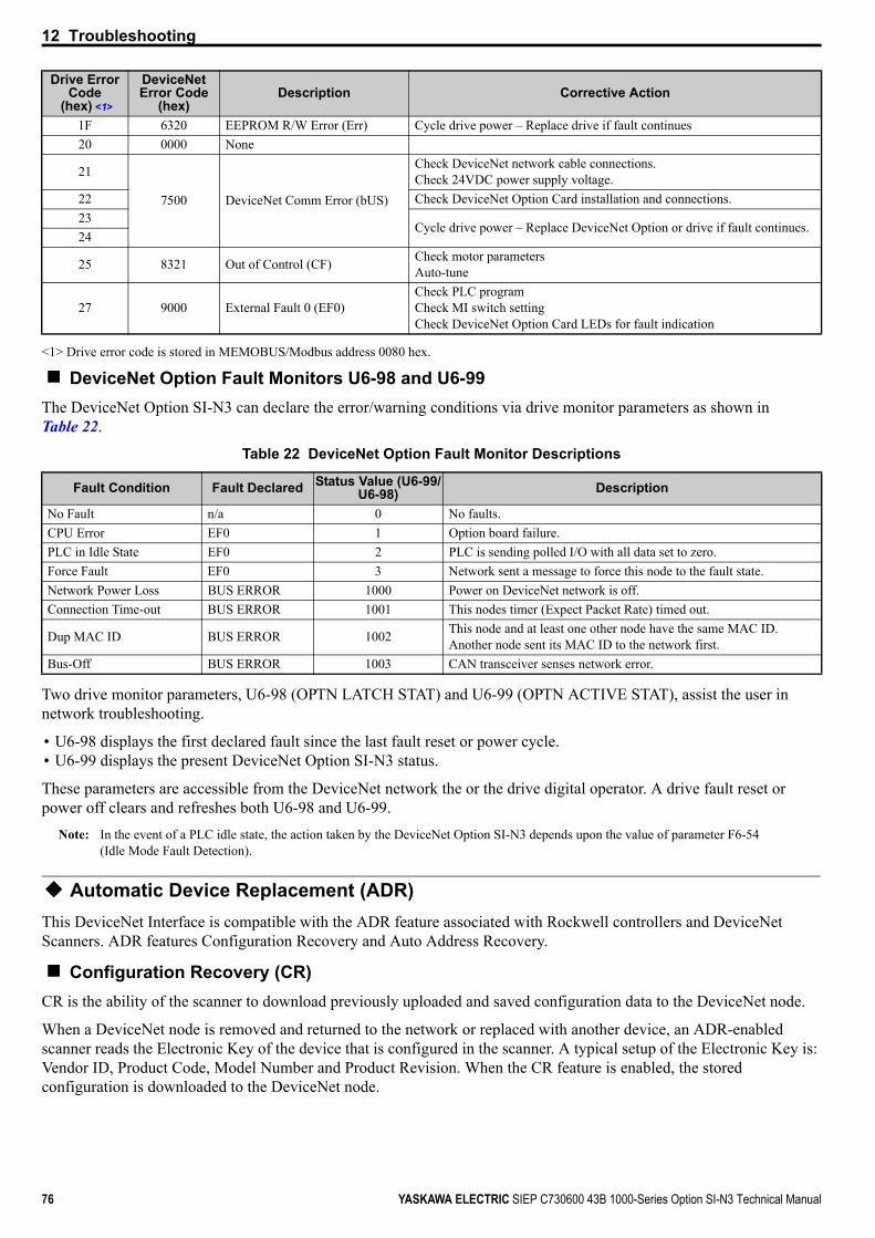
12 Troubleshooting
76 YASKAWA ELECTRIC SIEP C730600 43B 1000-Series Option SI-N3 Technical Manual
DeviceNet Option Fault Monitors U6-98 and U6-99The DeviceNet Option SI-N3 can declare the error/warning conditions via drive monitor parameters as shown in Table 22.
Table 22 DeviceNet Option Fault Monitor Descriptions
Two drive monitor parameters, U6-98 (OPTN LATCH STAT) and U6-99 (OPTN ACTIVE STAT), assist the user in network troubleshooting.
• U6-98 displays the first declared fault since the last fault reset or power cycle.• U6-99 displays the present DeviceNet Option SI-N3 status.
These parameters are accessible from the DeviceNet network the or the drive digital operator. A drive fault reset or power off clears and refreshes both U6-98 and U6-99.
Note: In the event of a PLC idle state, the action taken by the DeviceNet Option SI-N3 depends upon the value of parameter F6-54 (Idle Mode Fault Detection).
Automatic Device Replacement (ADR)This DeviceNet Interface is compatible with the ADR feature associated with Rockwell controllers and DeviceNet Scanners. ADR features Configuration Recovery and Auto Address Recovery.
Configuration Recovery (CR)CR is the ability of the scanner to download previously uploaded and saved configuration data to the DeviceNet node.
When a DeviceNet node is removed and returned to the network or replaced with another device, an ADR-enabled scanner reads the Electronic Key of the device that is configured in the scanner. A typical setup of the Electronic Key is: Vendor ID, Product Code, Model Number and Product Revision. When the CR feature is enabled, the stored configuration is downloaded to the DeviceNet node.
1F 6320 EEPROM R/W Error (Err) Cycle drive power – Replace drive if fault continues20 0000 None
21
7500 DeviceNet Comm Error (bUS)
Check DeviceNet network cable connections.Check 24VDC power supply voltage.
22 Check DeviceNet Option Card installation and connections.23
Cycle drive power – Replace DeviceNet Option or drive if fault continues.24
25 8321 Out of Control (CF) Check motor parametersAuto-tune
27 9000 External Fault 0 (EF0)Check PLC programCheck MI switch settingCheck DeviceNet Option Card LEDs for fault indication
<1> Drive error code is stored in MEMOBUS/Modbus address 0080 hex.
Fault Condition Fault Declared Status Value (U6-99/U6-98) Description
No Fault n/a 0 No faults.CPU Error EF0 1 Option board failure.PLC in Idle State EF0 2 PLC is sending polled I/O with all data set to zero.Force Fault EF0 3 Network sent a message to force this node to the fault state.Network Power Loss BUS ERROR 1000 Power on DeviceNet network is off.Connection Time-out BUS ERROR 1001 This nodes timer (Expect Packet Rate) timed out.
Dup MAC ID BUS ERROR 1002 This node and at least one other node have the same MAC ID. Another node sent its MAC ID to the network first.
Bus-Off BUS ERROR 1003 CAN transceiver senses network error.
Drive Error Code
(hex) <1>
DeviceNet Error Code
(hex)Description Corrective Action

12 Troubleshooting
YASKAWA ELECTRIC SIEP C730600 43B 1000-Series Option SI-N3 Technical Manual 77
If the scanner reads the Configuration Consistency Value (CCV), it will use this value to determine if a download will occur. If the CCV in the scanner does not equal the CCV in the DeviceNet node, the configuration information saved in the scanner will be downloaded to the DeviceNet node. In this implementation of DeviceNet, the CCV will always be 0.
Auto Address Recovery (AAR)AAR is the ability of the scanner to change the MAC ID of a node to a predetermined MAC ID. To use this feature the DeviceNet node must have its MAC ID switch (F6-50) set to 64 and its actual MAC ID (F6-63) equal to 63.
If the recovering node is a replacement for another device, putting the new device on the network enables the AAR feature. A scanner with AAR enabled will search the network for a node with a MAC ID of 63 and then read its Electronic Key. If the Electronic Key matches the node being replaced, the scanner will change these MAC ID of the found device to the MAC ID of the device it is replacing.
After the MAC ID is changed, the device sends its duplicate MAC IDs and executes the CR feature. Example: With current Rockwell PLCs, the AAR feature can only be enabled if the CR feature is also enabled.

78 YASKAWA ELECTRIC SIEP C730600 43B 1000-Series Option SI-N3 Technical Manual
13 Trunk Line and Drop Line Length
13 Trunk Line and Drop Line LengthRefer to www.odva.org for more information regarding wiring DeviceNet networks.
Trunk LineThe maximum allowable trunk line length depends on the type of cable used and the network baud rate. The total cable length includes the length of the trunk and the sum of all the drop lines.
Table 23 Trunk Line Cable Length
To calculate the maximum total length for trunk lines of mixed thick and thin cables, use the following formulas:
• 125 kbps: Lthick + (5 x Lthin) ≤ 500 m (1640 ft.)• 250 kbps: Lthick + (2.5 x Lthin) ≤ 250 m (787 ft.)• 500 kbps: Lthick + Lthin ≤ 100 m (328 ft.)
Drop Line The drop line is measured from the tap on the trunk line to the transceiver of the DeviceNet node. The total cable length includes the length of the trunk and the sum of all the drop lines.
Table 24 Drop Line Cable Length
Baud Rate (kbps) Thick Cable Thin Cable125 500 m (1640 ft.) 100 m (328 ft.)250 250 m (787 ft.) 100 m (328 ft.)500 100 m (328 ft.) 100 m (328 ft.)
Baud Rate (kbps) Maximum at Each Drop Maximum Total125
6 m (20 ft.)156 m (511 ft.)
250 78 m (256 ft.)500 39 m (128 ft.)

14 Specifications
YASKAWA ELECTRIC SIEP C730600 43B 1000-Series Option SI-N3 Technical Manual 79
14 SpecificationsTable 25 Option Specifications
Items SpecificationsModel SI-N3
SI-N3 Supported Messages
• Group 2 Server (UCMM capable).• Explicit Messages: Fragmentation is supported. Up to 32 bytes can be input and output.• Polled I/O Messages: Fragmentation is not supported. Up to 8 bytes can be input and output.• Faulted Node Recovery / Offline Connection Set Messages / Automatic Device Replacement (ADR).• Change of State Message (COS). COS can be used as an I/O Input Assembly.
I/O Assembly Instance Input: 17 types (4~8 bytes)Output: 18 types (4~8 bytes)
DeviceNet Specification Conformance Level 19: PassedDeviceNet Profile AC Drive
Input Power Voltage: 11~25 VdcCurrent: 40 mA
Connector Type 5-pin open-style screw connector
Physical Layer Type Isolated Physical LayerCAN transceiver + photocoupler
MAC ID Setting Programmable from drive keypad or network:MAC ID 0 to 63
Communications Speed/Baud Rate
Programmable from drive keypad or network:• 125/250/500 kbps• Auto Baud Rate• Idle Mode Detect• Heartbeat
Ambient Temperature -10 °C to +50 °C (14 °F to 122 °F)Humidity 95% RH or lower with no condensationStorage Temperature -20 °C to +60 °C (-4 °F to 140 °F) allowed for short-term transport of the productArea of Use Indoor (free of corrosive gas, airborne particles, etc.)Altitude 1000 m (3280 ft.) or lower
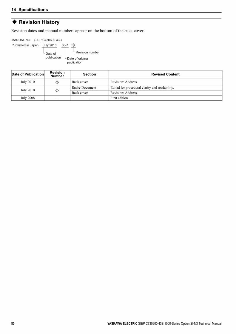
14 Specifications
80 YASKAWA ELECTRIC SIEP C730600 43B 1000-Series Option SI-N3 Technical Manual
Revision HistoryRevision dates and manual numbers appear on the bottom of the back cover.
Date of Publication Revision Number Section Revised Content
July 2010 Back cover Revision: Address
July 2010Entire Document Edited for procedural clarity and readability.Back cover Revision: Address
July 2008 − − First edition
MANUAL NO. SIEP C730600 43BPublished in Japan July 2010 08-7
Date of publication Date of original
publication
Revision number
1
2
1

DRIVE CENTER (INVERTER PLANT)2-13-1, Nishimiyaichi, Yukuhashi, Fukuoka, 824-8511, JapanPhone: 81-930-25-3844 Fax: 81-930-25-4369http://www.yaskawa.co.jp
YASKAWA ELECTRIC CORPORATIONNew Pier Takeshiba South Tower, 1-16-1, Kaigan, Minatoku, Tokyo, 105-6891, JapanPhone: 81-3-5402-4502 Fax: 81-3-5402-4580http://www.yaskawa.co.jp
YASKAWA AMERICA, INC.2121 Norman Drive South, Waukegan, IL 60085, U.S.A.Phone: (800) YASKAWA (927-5292) or 1-847-887-7000 Fax: 1-847-887-7310http://www.yaskawa.com
YASKAWA ELÉTRICO DO BRASIL LTDA.Avenda Fagundes Filho, 620 Bairro Saude, São Paulo, SP04304-000, BrasilPhone: 55-11-3585-1100 Fax: 55-11-5581-8795http://www.yaskawa.com.br
YASKAWA EUROPE GmbHHauptstrasse 185, 65760 Eschborn, GermanyPhone: 49-6196-569-300 Fax: 49-6196-569-398http://www.yaskawa.eu.com
YASKAWA ELECTRIC UK LTD.1 Hunt Hill Orchardton Woods, Cumbernauld, G68 9LF, United KingdomPhone: 44-1236-735000 Fax: 44-1236-458182http://www.yaskawa.co.uk
YASKAWA ELECTRIC KOREA CORPORATION7F, Doore Bldg. 24, Yeoido-dong, Yeoungdungpo-gu, Seoul, 150-877, KoreaPhone: 82-2-784-7844 Fax: 82-2-784-8495http://www.yaskawa.co.kr
YASKAWA ELECTRIC (SINGAPORE) PTE. LTD.151 Lorong Chuan, #04-01, New Tech Park, 556741, SingaporePhone: 65-6282-3003 Fax: 65-6289-3003http://www.yaskawa.com.sg
YASKAWA ELECTRIC (SHANGHAI) CO., LTD.No. 18 Xizang Zhong Road, 17F, Harbour Ring Plaza, Shanghai, 200001, ChinaPhone: 86-21-5385-2200 Fax: 86-21-5385-3299http://www.yaskawa.com.cn
YASKAWA ELECTRIC (SHANGHAI) CO., LTD. BEIJING OFFICERoom 1011, Tower W3 Oriental Plaza, No. 1 East Chang An Ave., Dong Cheng District, Beijing, 100738, ChinaPhone: 86-10-8518-4086 Fax: 86-10-8518-4082
YASKAWA ELECTRIC TAIWAN CORPORATION9F, 16, Nanking E. Rd., Sec. 3, Taipei, 104, TaiwanPhone: 886-2-2502-5003 Fax: 886-2-2505-1280
英文 No.10-5 (A4) インバータ製品用
YASKAWA ELECTRIC CORPORATION
In the event that the end user of this product is to be the military and said product is to be employed in any weapons systems or the manufacture thereof, the export will fall under the relevant regulations as stipulated in the Foreign Exchange and Foreign Trade Regulations. Therefore, be sure to follow all procedures and submit all relevant documentation according to any and all rules, regulations and laws that may apply.
Specifications are subject to change without notice for ongoing product modifications and improvements.
© 2008-2010 YASKAWA ELECTRIC CORPORATION. All rights reserved.
YASKAWA
Published in Japan July 2010 08-7
MANUAL NO. SIEP C730600 43B
10-7-52 -0
Technical ManualDeviceNetYASKAWA AC Drive1000-Series Option