Embed Size (px)
Citation preview
© 2016 Moxa Inc., All rights reserved.
The MOXA logo is a registered trademark of Moxa Inc. All other logos appearing in this catalog are the intellectual property of the respective company, product, or organization associated with the logo. P/N: 1900001601400
Your Trusted Partner in AutomationMoxa is a leading provider of edge connectivity, industrial computing, and network infrastructure solutions for enabling connectivity for the Industrial Internet of Things. With over 25 years of industry experience, Moxa has connected more than 40 million devices worldwide and has a distribution and service network that reaches customers in more than 70 countries. Moxa delivers lasting business value by empowering industry with reliable networks and sincere service for industrial communications infrastructures.
Moxa Sales and Marketing HeadquartersMoxa Corporate Plaza601 Valencia Ave., Suite 200Brea, CA 92823, U.S.A.Toll Free: 1-888-669-2872Tel: +1-714-528-6777Fax: [email protected]
The AmericasMoxa AmericasToll Free: 1-888-MOXA-USATel: +1-714-528-6777Fax: [email protected]
EuropeMoxa GermanyTel: +49-89-37003-99-0Fax: [email protected]
Asia-PacificMoxa Asia-Pacific and TaiwanTel: +886-2-8919-1230Fax: [email protected]@[email protected]
ChinaMoxa ShanghaiTel: +86-21-5258-9955Fax: [email protected]
Moxa Brazil Tel: +55-11-2495-3555Fax: [email protected]
Moxa India Tel: +91-80-4172-9088Fax: [email protected]
Moxa Beijing Tel: +86-10-5976-6123/24/25/26Fax: [email protected]
Moxa RussiaTel: +7-495-287-0929Fax: [email protected]
Moxa Shenzhen Tel: +86-755-8368-4084/94Fax: [email protected]
Moxa UK Tel: +44-1844-355-601Fax: [email protected]
Moxa KoreaTel: +82-31-625-4048Fax: [email protected]
Moxa France Tel: +33-1-30-85-41-80Fax: [email protected] Design and
Engineering HeadquartersFl. 4, No. 135, Lane 235, Baoqiao Rd.Xindian Dist., New Taipei City,Taiwan, R.O.C.Tel: +886-2-8919-1230Fax: +886-2-8919-1231
1 2www.moxa.com/SmartGrid www.moxa.com/substation
IEC 61850 Makes Substations Smarter
IntroductionPower substation technology has evolved considerably since the
first power distribution system went into service in the late 1800’s.
Today, several hundred thousand substations of various sizes and
varieties are in operation around the world, with both retrofit and
new substation projects being initiated with increasing frequency.
To get a better handle on the enormity of the situation, one study
(Pike Research) estimates that 150,000 substations are expected
to be fully automated by the year 2020.
Let's take a close look at the benefits and advantages offered by
the IEC 61850 standard. While the prospect of implementing such
a complex set of rules, regulations, and stringent specification
requirements may at first seem daunting, the advantages by far
outweigh the disadvantages. For example, whereas the thousands
of devices making up a traditional substation use hard-wired
device-to-device connections running relatively low speed serial
connections over copper wiring, the IEDs (intelligent electronic
devices) in a modern IEC 61850 substation connect to a
high-speed Ethernet bus, making it relatively easy to implement a
comprehensive management, maintenance, and control strategy
via a centralized power SCADA system.
Why Invest in an IEC 61850 Substation?Whether you’re looking to retrofit an existing substation, or build
a new one from the ground up, the advantages of implementing
the IEC 61850 standard are the same:
Simplified Architecture: The thousands of IEDs in a modern
substation use localized intelligence to handle much of the
decision making required at the local site, and communicate with
other devices via Ethernet switch, which themselves are
connected to the substation’s Ethernet network.
Greater Reliability: By design, the IEC 61850 standard places
great emphasis on reliability. Not only are many of the devices
required to be rugged enough to withstand extreme
environmental conditions, you can expect the network itself to be
redundant on many different levels.
Future-Proof Design: One of the major advantages of
implementing an Ethernet network is that it is easy to expand
when the need arises. In addition, any new products that
connect to an existing IEC 61850 substation are required to be
fully compatible with what’s already there.
Vendor-Independence: The fact that IEC 61850 products
produced by different companies are all required to speak the
same language gives substation System Integrators (SIs) a huge
advantage, since they can pick and choose the best products
from different vendors.
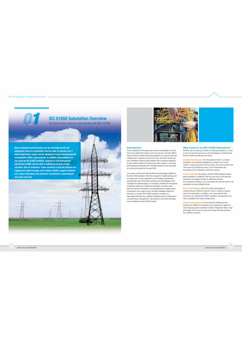
GGoGoGoGo ffrofrofrofrofrom wm wm wm wm wiireireireireire crcr-crcrcrazyazyazyazyazyy tototototo iwwiwwwwiwwiwwwwiwwwirere-re-rere smammmmsmamsmamsmamsmam rtrtrtrt rt witwitwitwitwith Ih Ih IIIIh I h Ih h Ih Ih h ECECECECECEC 6186186181866185050505050IEIEIEIECCCC 61616161858585850000 SSuSuSubbsbsbsttatatatataatititiiononnon OOOOvevevervvvvvvrvvrvvvvvrvviieieiewww
Since substation environments can be extremely harsh, the equipment used at a substation must be able to operate over a wide temperature range, and be designed to meet electromagnetic compatibility (EMC) requirements. In addition, the products you use must be IEC 61850 certified, resistant to electromagnetic interference (EMI), and be able to withstand periods of high vibration. One of customers’ main concerns is that the devices are rugged and robust enough, since highly reliable, rugged solutions can reduce downtime, and minimize maintenance requirements and wear-and-tear.
3 4
IEC 61850 Makes Substations Smarter
What is IEC 61850?The non-proprietary IEC 61850 standard uses modern object
oriented programming principles to define a complete virtual
model of the substation, which can be tested and tweaked in a
computer model before being implemented with actual
devices. Since the standard is open, any hardware vendor can
provide IEC 61850 compliant products, giving substation
engineers the freedom to pick and choose the best products
for their particular project. Highlights of the standard include:
The main data pathways use Ethernet-based communication,
with high bandwidth trunk lines used to transmit data packets
sent from multiple devices connected to the network.
Guaranteed compatibility with IEC 61850 compliant products
from different vendors, making it much easier to expand a
substation’s operation when the need arises.
The IEC 61850 standard makes heavy use of the XML-based
substation configuration language (SCL) to define the
configuration parameters of the multitudes of IEDs used in the
substation.
High speed IED-to-IED communication with transfer times
guaranteed using priority tagging of the Ethernet frames.
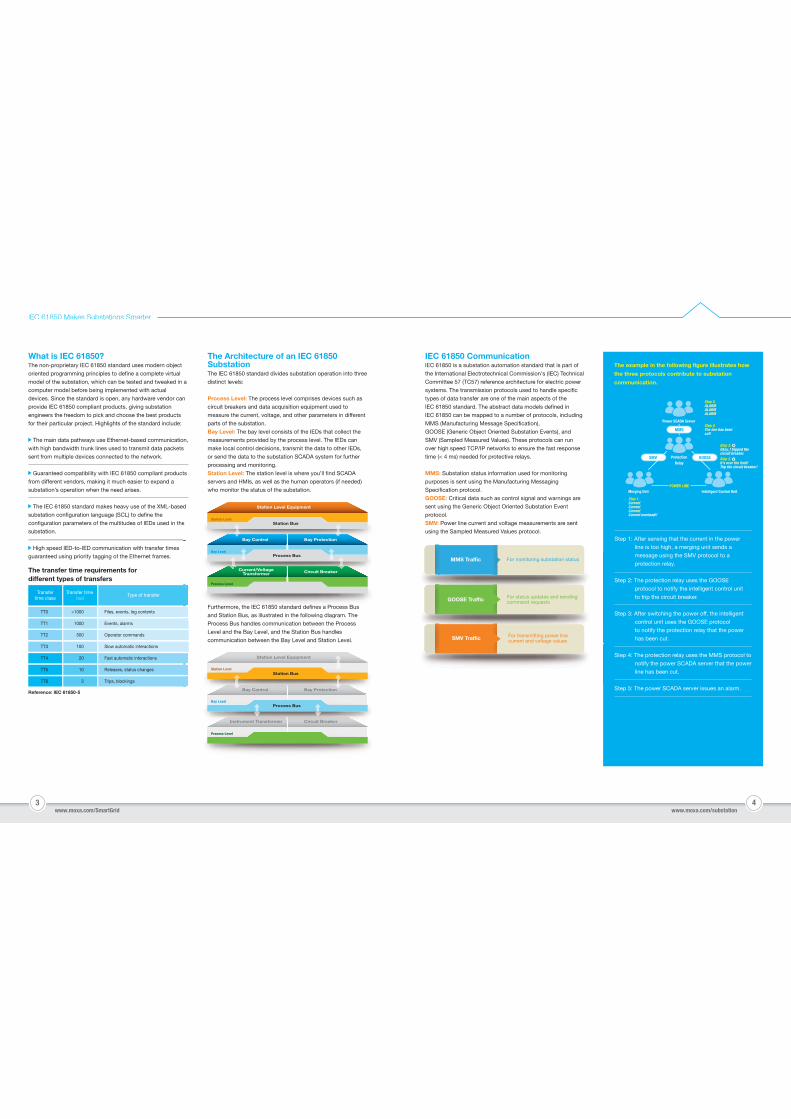
The transfer time requirements for different types of transfers
Reference: IEC 61850-5
Transfertime class
TT0 Files, events, log contents>1000
Events, alarms1000TT1
Operator commands500TT2
Slow automatic interactions100TT3
Fast automatic interactions20TT4
Releases, status changes10TT5
Trips, blockings3TT6
Transfer time (ms)
Type of transfer
The Architecture of an IEC 61850 SubstationThe IEC 61850 standard divides substation operation into three
distinct levels:
Process Level: The process level comprises devices such as
circuit breakers and data acquisition equipment used to
measure the current, voltage, and other parameters in different
parts of the substation.
Bay Level: The bay level consists of the IEDs that collect the
measurements provided by the process level. The IEDs can
make local control decisions, transmit the data to other IEDs,
or send the data to the substation SCADA system for further
processing and monitoring.
Station Level: The station level is where you’ll find SCADA
servers and HMIs, as well as the human operators (if needed)
who monitor the status of the substation.
Furthermore, the IEC 61850 standard defines a Process Bus
and Station Bus, as illustrated in the following diagram. The
Process Bus handles communication between the Process
Level and the Bay Level, and the Station Bus handles
communication between the Bay Level and Station Level.
IEC 61850 CommunicationIEC 61850 is a substation automation standard that is part of
the International Electrotechnical Commission's (IEC) Technical
Committee 57 (TC57) reference architecture for electric power
systems. The transmission protocols used to handle specific
types of data transfer are one of the main aspects of the
IEC 61850 standard. The abstract data models defined in
IEC 61850 can be mapped to a number of protocols, including
MMS (Manufacturing Message Specification),
GOOSE (Generic Object Oriented Substation Events), and
SMV (Sampled Measured Values). These protocols can run
over high speed TCP/IP networks to ensure the fast response
time (< 4 ms) needed for protective relays.
MMS: Substation status information used for monitoring
purposes is sent using the Manufacturing Messaging
Specification protocol.
GOOSE: Critical data such as control signal and warnings are
sent using the Generic Object Oriented Substation Event
protocol.
SMV: Power line current and voltage measurements are sent
using the Sampled Measured Values protocol.
www.moxa.com/SmartGrid www.moxa.com/substation
The example in the following figure illustrates how
the three protocols contribute to substation
communication.
Power SCADA Server
Step 5.ALARMALARMALARM
Step 2.It's over the limit!Trip the circuit breaker!
Step 4.The line has beencut!
Step 3.Okay, I tripped the circuit breaker.
Step 1.CurrentCurrentCurrentCurrent overload!!
ProtectionRelay
Merging Unit Intelligent Control UnitPOWER LINE
MMS
Step 1: After sensing that the current in the power
line is too high, a merging unit sends a
message using the SMV protocol to a
protection relay.
Step 2: The protection relay uses the GOOSE
protocol to notify the intelligent control unit
to trip the circuit breaker.
Step 3: After switching the power off, the intelligent
control unit uses the GOOSE protocol
to notify the protection relay that the power
has been cut.
Step 4: The protection relay uses the MMS protocol to
notify the power SCADA server that the power
line has been cut.
Step 5: The power SCADA server issues an alarm.
Station Level Equipment
d
e
d Station Level Equipment
Station BusStation Level
e
Process Bus
Bay Control Bay Protection
Bay Level
F
and Station Bus, as illustrated in the following diagram. The
Furthermore, the IECIEC 618561850 sta0 t ndardd d defid fines a Process Bus
and Station Bus, as illustrated in the following diagram. The
Station Level EquipmentCurrent/VoltageTransformer Circuit Breaker
Process Level
Station Level Equipment
Station BusStation Level
Process Bus
Bay Control Bay Protection
Bay Level
Instrument Transformer Circuit Breaker
Process Level
For monitoring substation statusMMS Traffic
For status updates and sending command requestsGOOSE Traffic
For transmitting power line current and voltage valuesSMV Traffic
SMV GOOSE
5 6
IEC 61850 Makes Substations Smarter
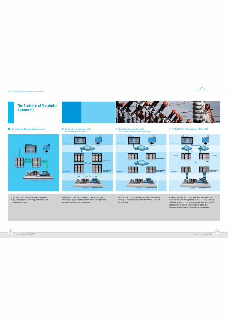
Conventional Substation Automation Substation Automation with IEC 61850 Station Bus
PRP/HSR: The Next Wave of IEC 61850Substation Automation withIEC 61850 Station and Process Bus
www.moxa.com/SmartGrid www.moxa.com/substation
The release of the IEC 61850 Station Bus protocol in the
1980’s was a big first step forward on the way to implementing
a substation-wide all-purpose network.
In 2005, the IEC 61850 standard was greatly improved by
defining a Process Bus to connect the Process Level with
the Bay Level.
The latest development in the IEC 61850 standard was the
inclusion of the PRP/HSR protocol in 2010. PRP/HSR (parallel
redundancy protocol / high-availability seamless redundancy)
specifies how to use two Ethernet networks to ensure
seamless failover if one of the redundant networks fails.
In the 1960’s a conventional substation was rather
bulky, with copper or fiber wiring used to hard-wire
one device to another.
The Evolution of SubstationAutomation
SCADA Server
Station Cubicles
Bay Cubicles
IEC 61850 Station Bus
HMI
Protection RelaysPoint-to-PointHard-Wired
Point-to-PointCopper Wire
Digital Sensor andControl Units
Gas Insulated Substation
HMISCADA Cubicle
Point-to-PointHard-Wired
Protection Cubicles Control Cubicles
Gas Insulated Substation
SCADA Server
Station Cubicles
Bay Cubicles
IEC 61850 Station Bus
HMI
Protection Relays
Digital Sensor andControl Units
Gas Insulated Substation
IEC 61850 Process Bus
SCADA Server
Station Cubicles
Bay Cubicles
HMI
Digital Sensor andControl Units
Gas Insulated Substation
Coupling Coupling
ProtectionRelays
HSR
LAN BLAN A
PRP PRP
Device Variety
7 8www.moxa.com/SmartGrid www.moxa.com/substation
IEC 61850 Makes Substations Smarter
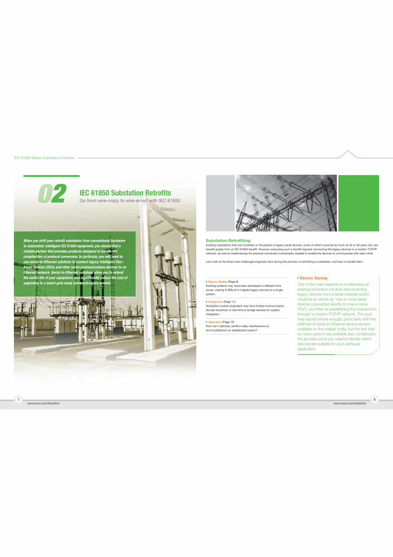
Substation RetrofittingExisting substations that use hundreds or thousands of legacy serial devices, some of which could be as much as 20 or 30 years old, can
benefit greatly from an IEC 61850 facelift. However, executing such a facelift requires connecting the legacy devices to a modern TCP/IP
network, as well as implementing the protocol conversion functionality needed to enable the devices to communicate with each other.
Let's look at the three main challenges engineers face during the process of retrofitting a substation, and how to handle them.
When you shift your retrofit substation from conventional hardware to automated, intelligent IEC 61850 equipment, you should find a reliable partner that provides products designed to handle the complexities of protocol conversion. In particular, you will need to use serial-to-Ethernet solutions to connect legacy Intelligent Elec-tronic Devices (IEDs) and other serial communications devices to an Ethernet network. Serial-to-Ethernet solutions allow you to extend the useful life of your equipment, and significantly reduce the cost of upgrading to a smart-grid-ready communications system.
Go from wire-crazy to wire-smart with IEC 618502 IEC 61850 Substation Retrofits
Device Variety (Page 8)
Existing systems may have been developed in different time
zones, making it difficult to migrate legacy devices to a single
system.
Operation (Page 13)
How can I optimize, perform daily maintenance on,
and troubleshoot an established system?
Integration (Page 11)
Substation system engineers may have limited communication
domain knowhow or less time to bridge devices for system
integration.
One of the main aspects of modernizing an existing substation involves disconnectinglegacy devices from a serial network (whichcould be as simple as “one or more serialdevices connected directly to one or morePCs”), and then re-establishing the connections through a modern TCP/IP network. The goalmay sound simple enough, particularly with the plethora of serial-to-Ethernet device serversavailable on the market today, but the fact thatso many options are available also complicates the process since you need to identify whichdevices are suitable for your particular application.
9 10
IEC 61850 Makes Substations Smarter
www.moxa.com/SmartGrid www.moxa.com/substation
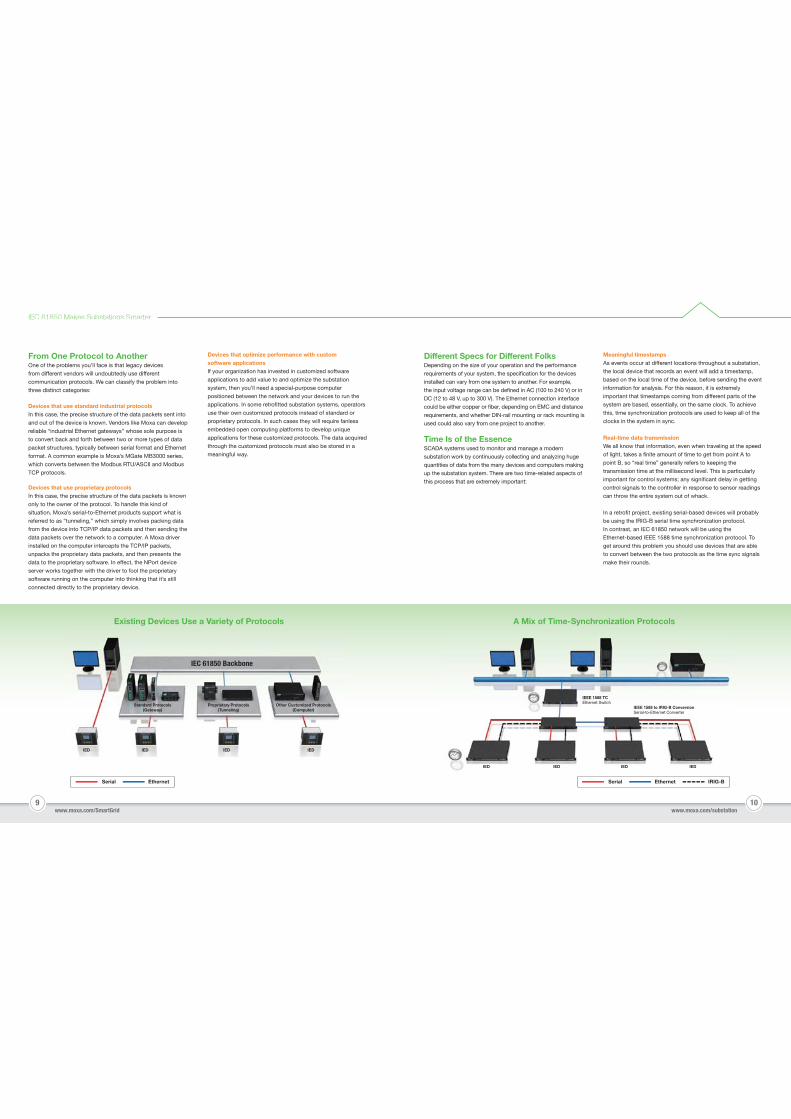
Existing Devices Use a Variety of Protocols
Different Specs for Different FolksDepending on the size of your operation and the performance
requirements of your system, the specification for the devices
installed can vary from one system to another. For example,
the input voltage range can be defined in AC (100 to 240 V) or in
DC (12 to 48 V, up to 300 V). The Ethernet connection interface
could be either copper or fiber, depending on EMC and distance
requirements, and whether DIN-rail mounting or rack mounting is
used could also vary from one project to another.
Time Is of the EssenceSCADA systems used to monitor and manage a modern
substation work by continuously collecting and analyzing huge
quantities of data from the many devices and computers making
up the substation system. There are two time-related aspects of
this process that are extremely important:
Devices that use standard industrial protocolsIn this case, the precise structure of the data packets sent into
and out of the device is known. Vendors like Moxa can develop
reliable “industrial Ethernet gateways” whose sole purpose is
to convert back and forth between two or more types of data
packet structures, typically between serial format and Ethernet
format. A common example is Moxa’s MGate MB3000 series,
which converts between the Modbus RTU/ASCII and Modbus
TCP protocols.
Meaningful timestampsAs events occur at different locations throughout a substation,
the local device that records an event will add a timestamp,
based on the local time of the device, before sending the event
information for analysis. For this reason, it is extremely
important that timestamps coming from different parts of the
system are based, essentially, on the same clock. To achieve
this, time synchronization protocols are used to keep all of the
clocks in the system in sync.
Real-time data transmissionWe all know that information, even when traveling at the speed
of light, takes a finite amount of time to get from point A to
point B, so “real time” generally refers to keeping the
transmission time at the millisecond level. This is particularly
important for control systems; any significant delay in getting
control signals to the controller in response to sensor readings
can throw the entire system out of whack.
In a retrofit project, existing serial-based devices will probably
be using the IRIG-B serial time synchronization protocol.
In contrast, an IEC 61850 network will be using the
Ethernet-based IEEE 1588 time synchronization protocol. To
get around this problem you should use devices that are able
to convert between the two protocols as the time sync signals
make their rounds.
From One Protocol to AnotherOne of the problems you’ll face is that legacy devices
from different vendors will undoubtedly use different
communication protocols. We can classify the problem into
three distinct categories:
A Mix of Time-Synchronization Protocols
Serial Ethernet
IEC 61850 Backbone
Standard Protocols(Gateway)
Proprietary Protocols(Tunneling)
Other Customized Protocols(Computer)
IEDIEDIEDIED
Serial Ethernet IRIG-B
IEEE 1588 TCEthernet Switch
IED IED IED IED
IEEE 1588 to IRIG-B ConversionSerial-to-Ethernet Converter
Devices that optimize performance with custom software applicationsIf your organization has invested in customized software
applications to add value to and optimize the substation
system, then you’ll need a special-purpose computer
positioned between the network and your devices to run the
applications. In some retrofitted substation systems, operators
use their own customized protocols instead of standard or
proprietary protocols. In such cases they will require fanless
embedded open computing platforms to develop unique
applications for these customized protocols. The data acquired
through the customized protocols must also be stored in a
meaningful way.
Devices that use proprietary protocolsIn this case, the precise structure of the data packets is known
only to the owner of the protocol. To handle this kind of
situation, Moxa’s serial-to-Ethernet products support what is
referred to as “tunneling,” which simply involves packing data
from the device into TCP/IP data packets and then sending the
data packets over the network to a computer. A Moxa driver
installed on the computer intercepts the TCP/IP packets,
unpacks the proprietary data packets, and then presents the
data to the proprietary software. In effect, the NPort device
server works together with the driver to fool the proprietary
software running on the computer into thinking that it’s still
connected directly to the proprietary device.
Dealing with Configuration IssuesA common issue seen in the installation phase is the configuration of serial-to-Ethernet devices. Especially in retrofit projects,
engineers would prefer to spend more time on performing system functional tests, rather than deal with communication issues.
Therefore, making the configuration as simple as possible would definitively improve the configuration efficiency of the entire project.
11 12
IEC 61850 Makes Substations Smarter
www.moxa.com/SmartGrid www.moxa.com/substation
Wide Range of Operating SystemsEngineers who deal with retrofit projects have always faced a wide variety of operating systems due to the fact that existing
substations were built over a period of time and are distributed across several geographical regions. Sometimes, the limitation comes
from needing to retain the legacy operating systems because the drivers used to read the end devices only work on these systems.
Sometimes, end users might want to use up-to-date operating systems because of their longevity. Therefore, an IEC 61850 solution
must support a wide range of drivers for serial-to-Ethernet devices on multiple operating systems.
A Platform Is Not Just a PlatformSince embedded computers are often used for customization, optimization, and multitasking, choosing a suitable hardware platform is
extremely important.
Native Compilation SupportEngineers have to deal with specific tool chains, source code, and binaries to compile software for multiple platforms.
A platform that supports a native compiler will make things much easier.
Operating SystemsThe embedded computer used in a serial-to-Ethernet solution is expected to do more than just protocol conversion. The operating system
and the packages supported will determine the time required to develop the solution.
Wireless CapabilityFor geographically-distributed substations, wireless solutions are usually chosen to provide communication and redundancy. However,
there are no rigorous certification processes to identify the stability of wireless solutions. Some wireless companies have defined their own
criteria for choosing a wireless platform for IEC 61850 substations.
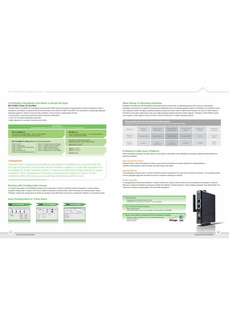
Moxa provides drivers for more than 20 operating systemsWe guarantee continuous driver/OS support for the best system interoperability and flexibility
Windows 8
Windows CE 5/6
Windows 7x86/x64
Windows 2000 Windows NT 4.0 Windows ME Windows 98 SE DOSLinux 3.0x86/x64
Linux 2.6x86/x64
Linux 2.4 Unixware 7 FreeBSDQNX 6QNX 4
SCO OpenServer 6
SCO OpenServer 5
Windows Server2008 x86/x64
Windows Server2003 x86/x64
Windows Vistax86/x64
Windows XPx86/x64
Windows XPEmbedded
Easy Configuration in Three StepsNative Compiler
Easy-to-Extend Software Packages
Ready-to-Run Wireless Computer with Data Acquisition Capability
‧‧PPrograPrograPrograg immingmmingmmingg ienviroenviroenviro tnmentnmentnment i ilsimilasimilasimila t Lr to Lr to Lr to Liinuxinuxinux‧D lDeveloDevelo tpmentpment p iis mucis much ih easih easier comer com dparedparedp tto croto cross-comss com ilipilingpilingp g
‧‧SSupporSupporSupporSupporpp its wirts wirts wirts wir lelesselesseless-eless blenableenableenableenabled fd funcd funcd funcd func itionstionstionstions dand reand reand reand rel dlatedlatedlatedlated d ldevelodevelodevelodevelopmentpmentpmentpmentp‧EthEthernEthern t tet-to-et to ll lcellulcellularar‧Serial-to-cellular
‧‧D biDebianDebianDebianDebian ARMARM sARM sARM s ARM supportupportupportupportpp‧O er 4Over 4Over 48 5758 5758,575, stablestablestable readread, read, toy-to-uy-to-uy se pacse pacse pacp kageskageskages,g , inclincluincluding Iding Iding Ig Psec aPsec aPsec and Netnd Netnd NetSNMPSNMPSNMP
Serial SettingsOperating Mode Network Settings
Integration
Engineers who manage power substations earmarked for retrofitting may be good at their job,but may not have the communication domain knowhow needed to convert their substation to afull-fledged IEC 61850 compliant system, or may have limited time to bridge devices for systemintegration. When deciding how to proceed, including which products to invest in for the transition to IEC 61850 status, you should keep the following points in mind:
Certification Standards Can Make or Break the DealIEC 61850-3 Class C3 Certified The IEC 61850-3 and IEEE 1613 standards precisely define EMC and communication requirements for network equipment used in
substations. Substation computers and Ethernet switches must have IEC 61850-3 and IEEE 1613 certification to guarantee adequate
protection against a variety of environmental conditions. These minimum requirements include:
• Level-4 EMC, to give strong protection against electrical interference
• -40 to 75°C ambient temperature tolerance
• High tolerances for constant vibrations and shocks
IEC 870-2-2Telecontrol Equipment and Systems — Part 2: Operating Conditions;Section 2: Environmental Conditions
Class C1: -5 to 45°CClass C2: -25 to 55°CClass C3: -40 to 70°CClass Cx: Special
IEC TS 61000-6-5Electromagnetic Compatibility (EMC) — Part 6-5: Generic Standards;Immumity for Power Station and Substation Environments
IEC TS 61000-4-x Series (Basic Immunity Standards)
61000-4-2 (ESD)61000-4-3 (Radiated RFI)61000-4-4 (Electrical Burst Fast Transients)61000-4-5 (Surge)61000-4-6 (Conducted RFI)61000-4-8 (Power Frequency Magnetic Field)
61000-4-11 (Voltage Dips, AC Power Supplies)61000-4-12 (Damped Oscillatory Transients)61000-4-16 (Mains Frequency Voltage)61000-4-17 (Ripple on DC Power Supplies)61000-4-29 (Voltage Dips, DC Power Supplies)
Class A: Air-conditioned locations (indoors)Class B: Heated and/or cooled enclosed conditionsClass C: Sheltered locationsClass D: Outdoor locations
IEC 61850-3Communications Networks and Systems in Substations — Part 3: General Requirements
Operating Mode111111 Network Settings22222 Serial Settings33333
13 14
IEC 61850 Makes Substations Smarter
www.moxa.com/SmartGrid www.moxa.com/substation
Performance and SecurityMost of the time, embedded computers in a substation are used
to run many different applications and operating systems. In
such cases, engineers would prefer to use virtualization
technology such as VMware to run independent virtual machines
(VMs), which provide the following benefits:
Reduced CostsVMs increase the efficiency and utilization level of your existing
x86 hardware platform.
Application IsolationDepending on the capability of your hardware platform, you can
run each application on a separate VM for complete isolation of
the applications. You can also run critical and non-critical
application workloads on separate VMs to ensure that if one set
of applications fails, the other applications will continue to run.
Extend the Life of Your Legacy ApplicationsYou can use VMs to run your legacy applications and OS on
computers with new hardware platforms or OSs.
However, don't assume that every computer platform works well
with VMware. Be sure to use products that display the
VMware-ready logo, which indicates that a product meets the
criteria for VMware integration and interoperability.
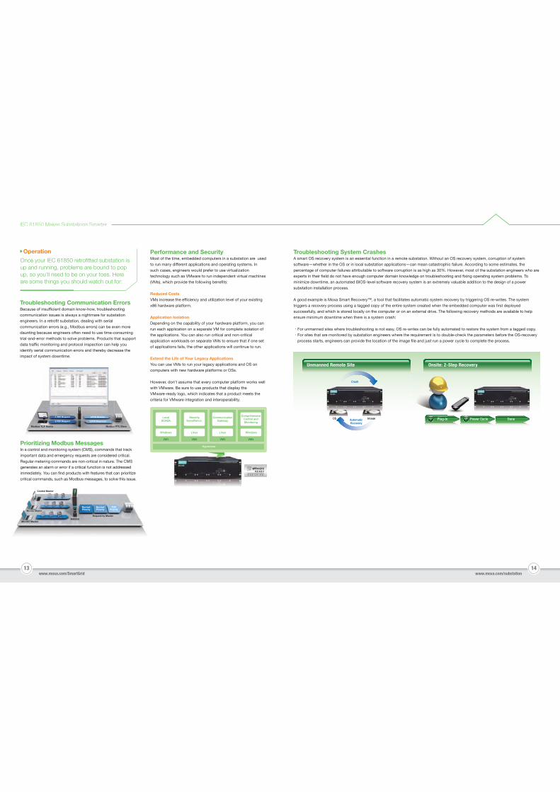
Troubleshooting System CrashesA smart OS recovery system is an essential function in a remote substation. Without an OS recovery system, corruption of system
software—whether in the OS or in local substation applications—can mean catastrophic failure. According to some estimates, the
percentage of computer failures attributable to software corruption is as high as 30%. However, most of the substation engineers who are
experts in their field do not have enough computer domain knowledge on troubleshooting and fixing operating system problems. To
minimize downtime, an automated BIOS-level software recovery system is an extremely valuable addition to the design of a power
substation installation process.
A good example is Moxa Smart Recovery™, a tool that facilitates automatic system recovery by triggering OS re-writes. The system
triggers a recovery process using a tagged copy of the entire system created when the embedded computer was first deployed
successfully, and which is stored locally on the computer or on an external drive. The following recovery methods are available to help
ensure minimum downtime when there is a system crash:
‧For unmanned sites where troubleshooting is not easy, OS re-writes can be fully automated to restore the system from a tagged copy.
‧For sites that are monitored by substation engineers where the requirement is to double-check the parameters before the OS-recovery
process starts, engineers can provide the location of the image file and just run a power cycle to complete the process.
Troubleshooting Communication ErrorsBecause of insufficient domain know-how, troubleshooting
communication issues is always a nightmare for substation
engineers. In a retrofit substation, dealing with serial
communication errors (e.g., Modbus errors) can be even more
daunting because engineers often need to use time-consuming
trial-and-error methods to solve problems. Products that support
data traffic monitoring and protocol inspection can help you
identify serial communication errors and thereby decrease the
impact of system downtime.
Control Master
Monitor Master
Monitor Master
Request by MasterMB3000
TOPPriority
NormalPriority
NormalPriority
Operation
Once your IEC 61850 retrofitted substation isup and running, problems are bound to pop up, so you’ll need to be on your toes. Hereare some things you should watch out for:
Prioritizing Modbus MessagesIn a control and monitoring system (CMS), commands that track
important data and emergency requests are considered critical.
Regular metering commands are non-critical in nature. The CMS
generates an alarm or error if a critical function is not addressed
immediately. You can find products with features that can prioritize
critical commands, such as Modbus messages, to solve this issue.
LocalSCADA
Windows
SecuritySurveillance
Linux
CommunicationGateway
Linux
ComprehensiveControl andMonitoring
Windows
Hypervisor
VM1 VM2 VM3 VM4
Prioritizing Modbus Messagesn a control and monitoring system (CMS) commands that track
1.TCP Request
4.TCP Request
2.RTU Request
3.RTU Response
Modbus RTU SlaveModbus TCP Master
1.TCP Request
4.TCP Request
2.RTU Request
3.RTU Response
ModbusCP Master
Unmanned Remote Site
111111 222222Plug-in Power Cycle DoneImageImagAutomaticRecovery
Crash
aggeaggeggeOS
Onsite: 2-Step Recovery
PerformanceOne of the major concerns of experienced substation engineers is
how the performance of an Ethernet-based substation compares
with the performance of a more traditional peer-to-peer,
hardwired substation. The concern is understandable, particularly
since in an Ethernet-based network, thousands of information
packets are constantly competing for a spot in the substation
network’s main trunk line. Someone unfamiliar with how an
advanced IEC 61850 substation network prioritizes packets to
ensure that critical information is passed quickly to the correct
devices is likely to be skeptical.
15 16www.moxa.com/SmartGrid www.moxa.com/substation
IEC 61850 Makes Substations Smarter
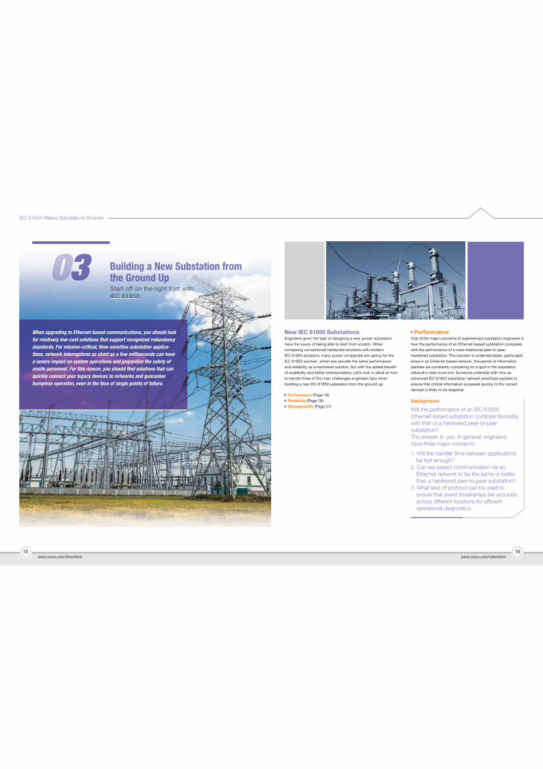
New IEC 61850 SubstationsEngineers given the task of designing a new power substation
have the luxury of being able to start from scratch. When
comparing conventional hardwired solutions with modern
IEC 61850 solutions, many power companies are opting for the
IEC 61850 solution, which can provide the same performance
and reliability as a hardwired solution, but with the added benefit
of scalability and better interoperability. Let’s look in detail at how
to handle three of the main challenges engineers face when
building a new IEC 61850 substation from the ground up:
When upgrading to Ethernet-based communications, you should look for relatively low-cost solutions that support recognized redundancy standards. For mission-critical, time-sensitive substation applica-tions, network interruptions as short as a few milliseconds can have a severe impact on system operations and jeopardize the safety of onsite personnel. For this reason, you should find solutions that can quickly connect your legacy devices to networks and guarantee bumpless operation, even in the face of single points of failure.
Statart rt offfo on hhthhe re righighight ft ffffffft ooooooootootootootoo wiiwiwiwiwiwwiwithththtttthththththIECCIECIECIEC 616161618508508508 0
Building a New Substation fromththee GrGrououndnd UUppp
Performance (Page 16)
Reliability (Page 18)
Manageability (Page 21)
1. Will the transfer time between applications be fast enough?2. Can we expect communication via an Ethernet network to be the same or better than a hardwired peer-to-peer substation?3. What kind of protocol can be used to ensure that event timestamps are accurate across different locations for efficient operational diagnostics.
Background
Will the performance of an IEC 61850 Ethernet-based substation compare favorably with that of a hardwired peer-to-peer substation?The answer is, yes. In general, engineers have three major concerns:
Standard QoSStandard QoS prioritizes packets depending on their
port-based configuration and the queue level. All packets in a
queue are transmitted based on a first-in-first-out sequence
within each queue level without undergoing a packet-type
inspection. For example, with this method, GOOSE packets
with the highest priority could be transmitted after other data
traffic.
IEC 61850 QoSIn IEC 61850 substation communication, GOOSE, SMV, and PTP
are 3 critical packet types that require high-priority attention. To
guarantee that these messages are not corrupted, they are
transmitted with the highest priority, regardless of what other
messages are queued up in the network. When an IEC 61850
queueing scheme is used, the Ethernet switch knows that
GOOSE, SMV, and PTP packets are critical, and hence always
gives these messages the top priority in the sending queue.
17 18
IEC 61850 Makes Substations Smarter
www.moxa.com/SmartGrid www.moxa.com/substation
IEC 61850 QoS: Critical Packet PrioritizationModern IEC 61850 Ethernet networks should apply an intelligent
QoS (Quality of Service) categorization method to ensure that the
most critical data packets can be forwarded with highest priority.
VLAN Technology: Enabling Efficient and Reliable CommunicationVLAN technology is used to group network devices by IP
address, instead of by physical location. That is, devices from
anywhere on the substation network can be assigned to the
same “virtual” LAN (abbreviated VLAN), whereas two devices
located right next to each other could be assigned to different
VLANs. VLANs provide substation networks with the following
benefits:
Trunk traffic reductionTraffic can be restricted to specific network domains by
assigning network devices to specific VLANs, and in this way
remove potential bottlenecks on the trunk line.
Traffic filteringA network device assigned to a particular VLAN filters out
packets sent from devices not on the same VLAN. This simple,
yet effective filtering strategy is used to segregate traffic
flow throughout the network.
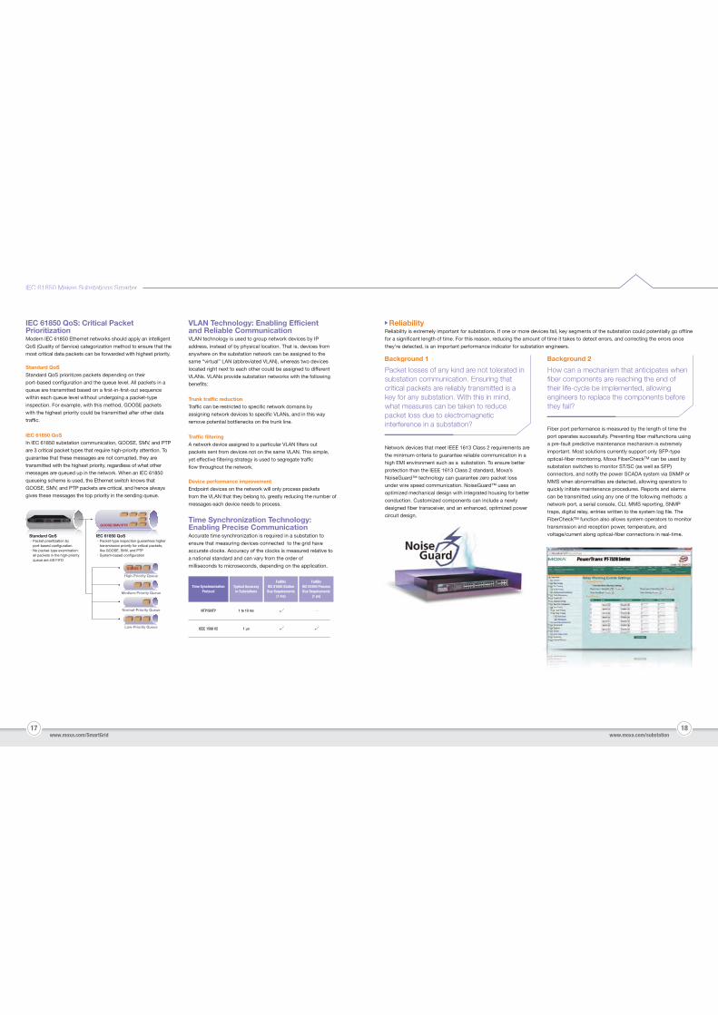
Time Synchronization Technology: Enabling Precise CommunicationAccurate time synchronization is required in a substation to
ensure that measuring devices connected to the grid have
accurate clocks. Accuracy of the clocks is measured relative to
a national standard and can vary from the order of
milliseconds to microseconds, depending on the application.
ReliabilityReliability is extremely important for substations. If one or more devices fail, key segments of the substation could potentially go offline
for a significant length of time. For this reason, reducing the amount of time it takes to detect errors, and correcting the errors once
they’re detected, is an important performance indicator for substation engineers.
Time SynchronizationProtocol
NTP/SNTP -
IEEE 1588 V2
1 to 10 ms
1 μs
Typical Accuracyin Substations
FulfillsIEC 61850 StationBus Requirements
(1 ms)
FulfillsIEC 61850 ProcessBus Requirements
(1 μs)
Device performance improvementEndpoint devices on the network will only process packets
from the VLAN that they belong to, greatly reducing the number of
messages each device needs to process.
Background 1
Packet losses of any kind are not tolerated in substation communication. Ensuring that critical packets are reliably transmitted is a key for any substation. With this in mind, what measures can be taken to reduce packet loss due to electromagnetic interference in a substation?
Background 2
How can a mechanism that anticipates when fiber components are reaching the end of their life-cycle be implemented, allowing engineers to replace the components before they fail?
Network devices that meet IEEE 1613 Class 2 requirements are
the minimum criteria to guarantee reliable communication in a
high EMI environment such as a substation. To ensure better
protection than the IEEE 1613 Class 2 standard, Moxa’s
NoiseGuard™ technology can guarantee zero packet loss
under wire speed communication. NoiseGuard™ uses an
optimized mechanical design with integrated housing for better
conduction. Customized components can include a newly
designed fiber transceiver, and an enhanced, optimized power
circuit design.
Fiber port performance is measured by the length of time the
port operates successfully. Preventing fiber malfunctions using
a pre-fault predictive maintenance mechanism is extremely
important. Most solutions currently support only SFP-type
optical-fiber monitoring. Moxa FiberCheckTM can be used by
substation switches to monitor ST/SC (as well as SFP)
connectors, and notify the power SCADA system via SNMP or
MMS when abnormalities are detected, allowing operators to
quickly initiate maintenance procedures. Reports and alarms
can be transmitted using any one of the following methods: a
network port, a serial console, CLI, MMS reporting, SNMP
traps, digital relay, entries written to the system log file. The
FiberCheckTM function also allows system operators to monitor
transmission and reception power, temperature, and
voltage/current along optical-fiber connections in real-time.
GOOSE
High-Priority Queue
Normal-Priority Queue
Low-Priority Queue
Medium-Priority Queue
GOOSE/SMV/PTP
IEC 61850 QoS‧Packet-type inspection guarantees higher transmission priority for critical packets, like GOOSE, SMV, and PTP‧System-based configuration
Standard QoS‧Packet prioritization by port-based configuration‧No packet-type examination: all packets in the high-priority queue are still FIFO
19 20
IEC 61850 Makes Substations Smarter
www.moxa.com/SmartGrid www.moxa.com/substation
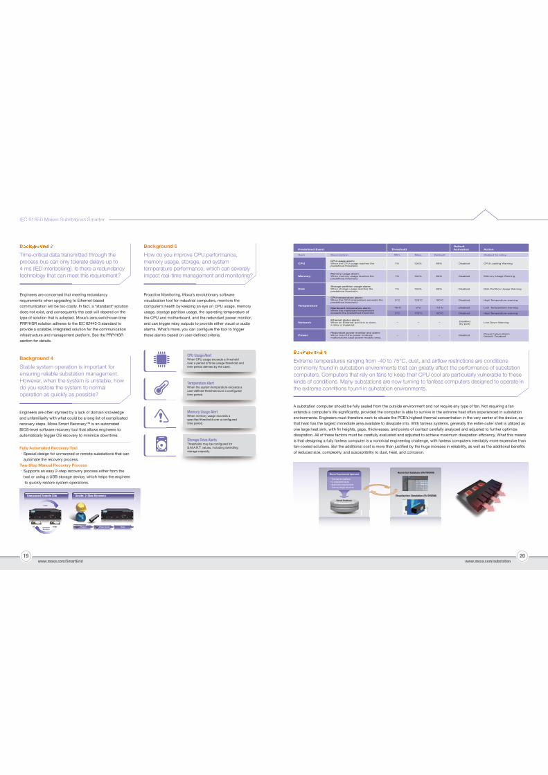
CPU Usage AlertWhen CPU usage exceeds a threshold over a period of time (usage threshold and time period defined by the user).
Storage Drive AlertsThresholds may be configured for S.M.A.R.T. values, including dwindling storage capacity.
Temperature AlertWhen the system temperature exceeds a user-defined threshold over a configured time period.
Memory Usage AlertWhen memory usage exceeds a specified threshold over a configured time period.
A substation computer should be fully sealed from the outside environment and not require any type of fan. Not requiring a fan
extends a computer’s life significantly, provided the computer is able to survive in the extreme heat often experienced in substation
environments. Engineers must therefore work to situate the PCB’s highest thermal concentration in the very center of the device, so
that heat has the largest immediate area available to dissipate into. With fanless systems, generally the entire outer shell is utilized as
one large heat sink, with fin heights, gaps, thicknesses, and points of contact carefully analyzed and adjusted to further optimize
dissipation. All of these factors must be carefully evaluated and adjusted to achieve maximum dissipation efficiency. What this means
is that designing a fully fanless computer is a nontrivial engineering challenge, with fanless computers inevitably more expensive than
fan-cooled solutions. But the additional cost is more than justified by the huge increase in reliability, as well as the additional benefits
of reduced size, complexity, and susceptibility to dust, heat, and corrosion.
Predefined Event Threshold ActionDefault Activation
Item
CPU
Memory
Power
Disk
Temperature
Network
Redundant power monitor and alarm: When one of the power modules malfunctions (dual-power models only).
Description
CPU usage alarm: When the CPU usage reaches the predefined threshold.
Memory usage alarm: When memory usage reaches the predefined threshold.
Storage partition usage alarm: When storage usage reaches the predefined threshold.
CPU temperature alarm: When the CPU temperature exceeds the predefined threshold.
Mainboard temperature alarm: When the mainboard temperature exceeds the predefined threshold.
Ethernet status alarm: When an Ethernet port link is down, a relay is triggered.
Min. Max.
1%
1%
1%
0°C
0°C
-40°C
–
–
–
–
–
–
100%
100%
100%
120°C
0°C
120°C
Default
80%
80%
80%
100°C
100°C
-15°C
Disabled
Disabled
Disabled
Disabled
Disabled
Disabled
Disabled(by port)
Disabled Power Failure AlarmDefault: Disabled
Output to relay
CPU Loading Warning
Memory Usage Warning
Disk Partition Usage Warning
High Temperature warning
Low Temperature warning
High Temperature warning
Link Down Warning
Time-critical data transmitted through the process bus can only tolerate delays up to 4 ms (IED interlocking). Is there a redundancy technology that can meet this requirement?
Background 5
How do you improve CPU performance, memory usage, storage, and system temperature performance, which can severely impact real-time management and monitoring?
Engineers are concerned that meeting redundancy
requirements when upgrading to Ethernet-based
communication will be too costly. In fact, a “standard” solution
does not exist, and consequently the cost will depend on the
type of solution that is adopted. Moxa’s zero-switchover-time
PRP/HSR solution adheres to the IEC 62443-3 standard to
provide a scalable, integrated solution for the communication
infrastructure and management platform. See the PRP/HSR
section for details.
Engineers are often stymied by a lack of domain knowledge
and unfamiliarity with what could be a long list of complicated
recovery steps. Moxa Smart Recovery™ is an automated
BIOS-level software recovery tool that allows engineers to
automatically trigger OS recovery to minimize downtime.
Background 4
Stable system operation is important for ensuring reliable substation management. However, when the system is unstable, how do you restore the system to normal operation as quickly as possible?
Proactive Monitoring, Moxa’s revolutionary software
visualization tool for industrial computers, monitors the
computer’s health by keeping an eye on CPU usage, memory
usage, storage partition usage, the operating temperature of
the CPU and motherboard, and the redundant power monitor,
and can trigger relay outputs to provide either visual or audio
alarms. What’s more, you can configure the tool to trigger
these alarms based on user-defined criteria.
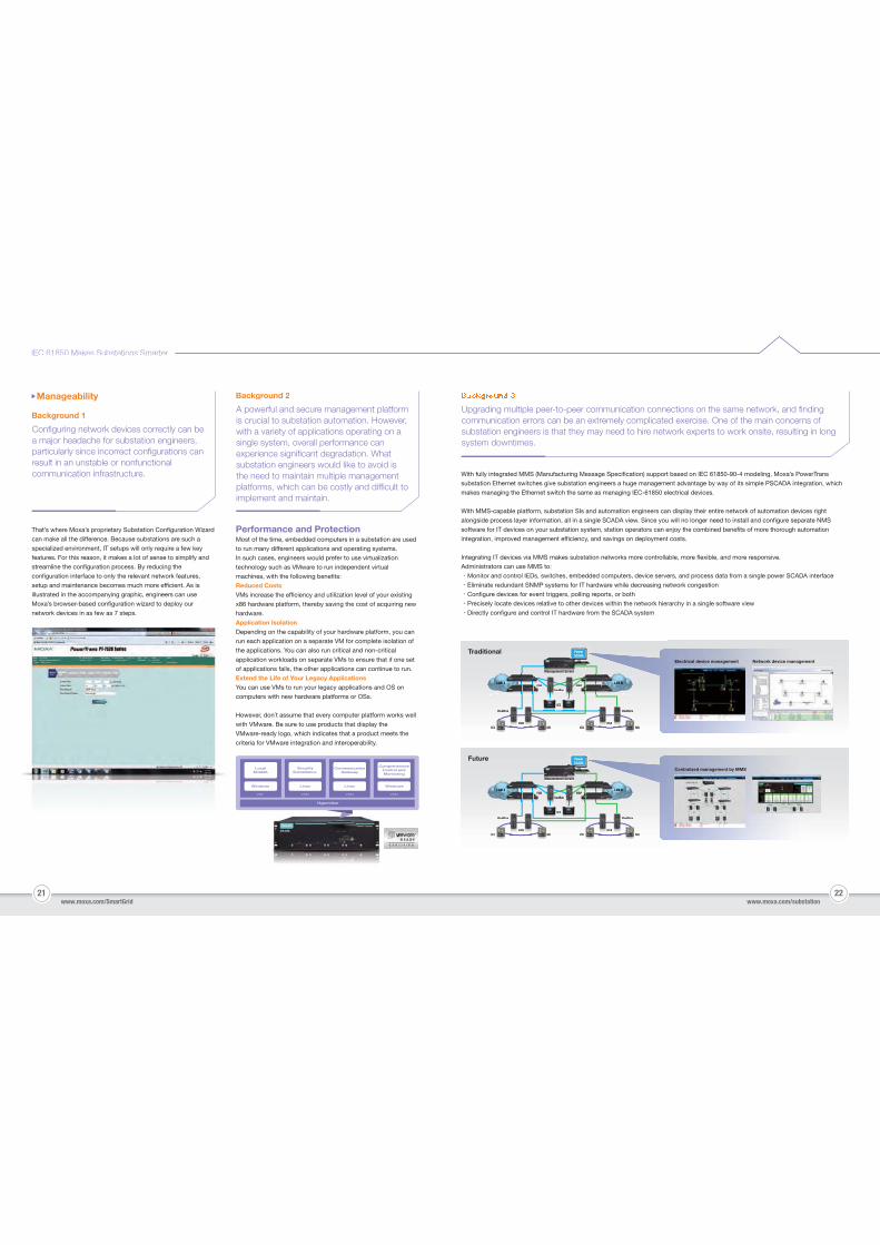
Extreme temperatures ranging from -40 to 75°C, dust, and airflow restrictions are conditionscommonly found in substation environments that can greatly affect the performance of substationcomputers. Computers that rely on fans to keep their CPU cool are particularly vulnerable to these kinds of conditions. Many substations are now turning to fanless computers designed to operate inthe extreme conditions found in substation environments.
Numerical Database (FloTHERM)
Visualization Simulation (FloTHERM)Vis
Result Database
Moxa’s Experimental Approach
Thermal test platformIC component studyApplication requirementsThermal design structure
Unmanned Remote Site
1111 2222Plug-in Power Cycle DoneImageImagAutomaticRecovery
Crash
aggeaggeggeOS
Onsite: 2-Step Recovery
Fully Automated Recovery Tool‧Special design for unmanned or remote substations that can
automate the recovery process.
Two-Step Manual Recovery Process‧Supports an easy 2-step recovery process either from the
tool or using a USB storage device, which helps the engineer
to quickly restore system operations.
21 22
IEC 61850 Makes Substations Smarter
www.moxa.com/SmartGrid www.moxa.com/substation
That’s where Moxa’s proprietary Substation Configuration Wizard
can make all the difference. Because substations are such a
specialized environment, IT setups will only require a few key
features. For this reason, it makes a lot of sense to simplify and
streamline the configuration process. By reducing the
configuration interface to only the relevant network features,
setup and maintenance becomes much more efficient. As is
illustrated in the accompanying graphic, engineers can use
Moxa’s browser-based configuration wizard to deploy our
network devices in as few as 7 steps.
LocalSCADA
Windows
SecuritySurveillance
Linux
CommunicationGateway
Linux
ComprehensiveControl andMonitoring
Windows
Hypervisor
VM1 VM2 VM3 VM4
Background 2
A powerful and secure management platform is crucial to substation automation. However, with a variety of applications operating on a single system, overall performance can experience significant degradation. What substation engineers would like to avoid is the need to maintain multiple management platforms, which can be costly and difficult to implement and maintain.
With fully integrated MMS (Manufacturing Message Specification) support based on IEC 61850-90-4 modeling, Moxa’s PowerTrans
substation Ethernet switches give substation engineers a huge management advantage by way of its simple PSCADA integration, which
makes managing the Ethernet switch the same as managing IEC-61850 electrical devices.
With MMS-capable platform, substation SIs and automation engineers can display their entire network of automation devices right
alongside process layer information, all in a single SCADA view. Since you will no longer need to install and configure separate NMS
software for IT devices on your substation system, station operators can enjoy the combined benefits of more thorough automation
integration, improved management efficiency, and savings on deployment costs.
Integrating IT devices via MMS makes substation networks more controllable, more flexible, and more responsive.
Administrators can use MMS to:
‧Monitor and control IEDs, switches, embedded computers, device servers, and process data from a single power SCADA interface
‧Eliminate redundant SNMP systems for IT hardware while decreasing network congestion
‧Configure devices for event triggers, polling reports, or both
‧Precisely locate devices relative to other devices within the network hierarchy in a single software view
‧Directly configure and control IT hardware from the SCADA system
Upgrading multiple peer-to-peer communication connections on the same network, and findingcommunication errors can be an extremely complicated exercise. One of the main concerns of substation engineers is that they may need to hire network experts to work onsite, resulting in long system downtimes.
Background 1
Configuring network devices correctly can be a major headache for substation engineers, particularly since incorrect configurations can result in an unstable or nonfunctional communication infrastructure.
Manageability
Performance and ProtectionMost of the time, embedded computers in a substation are used
to run many different applications and operating systems.
In such cases, engineers would prefer to use virtualization
technology such as VMware to run independent virtual
machines, with the following benefits:
Reduced CostsVMs increase the efficiency and utilization level of your existing
x86 hardware platform, thereby saving the cost of acquiring new
hardware.
Application IsolationDepending on the capability of your hardware platform, you can
run each application on a separate VM for complete isolation of
the applications. You can also run critical and non-critical
application workloads on separate VMs to ensure that if one set
of applications fails, the other applications can continue to run.
Extend the Life of Your Legacy ApplicationsYou can use VMs to run your legacy applications and OS on
computers with new hardware platforms or OSs.
However, don´t assume that every computer platform works well
with VMware. Be sure to use products that display the
VMware-ready logo, which indicates that a product meets the
criteria for VMware integration and interoperability.
LANLANLANANN BLAN AN BN BN BN BBN BN BN BBLAN BBNN
RedBoxPRP PRP
IED
PowerSCADA
LANLANLANAN AN AN N AN AN ALALANLANLALANLAANLALAANN ALANAN
HSR
RedBox
ICU MUHSR
RedBox
ICU MU
P P
S
MManagemenManagement St St ServerSet Serverr
LANNLANLANLLANLAANN BBAN BN BN BBN BN N BN BBN BBBB
RedBoxPRP PRP
IED
PowerSCADA
N AN AN AAN ALANLANLANLANAAN N LLALALALANANLAANLAANLALAN
HSR
RedBox
ICU MUHSR
RedBox
ICU MU
P P
S
MManagemenManagement St St ServerSet Serverr
Traditional
Future
Electrical device management
Centralized management by MMS
Network device management
23 24
IEC 61850 Makes Substations Smarter
www.moxa.com/SmartGrid www.moxa.com/substation
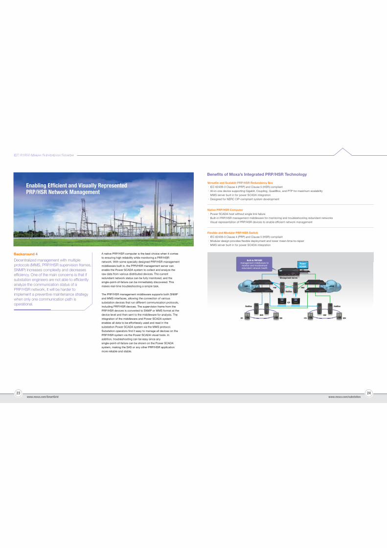
Benefits of Moxa’s Integrated PRP/HSR Technology
Versatile and Scalable PRP/HSR Redundancy Box‧IEC 62439-3 Clause 4 (PRP) and Clause 5 (HSR) compliant
‧All-in-one device supporting Gigabit, Coupling, QuadBox, and PTP for maximum scalability
‧MMS server built in for power SCADA integration
‧Designed for NERC CIP-compliant system development
Native PRP/HSR Computer‧Power SCADA host without single link failure
‧Built-in PRP/HSR management middleware for monitoring and troubleshooting redundant networks
‧Visual representation of PRP/HSR devices to enable efficient network management
A native PRP/HSR computer is the best choice when it comes
to ensuring high reliability while monitoring a PRP/HSR
network. With some specially designed PRP/HSR management
middleware built in, the PPR/HSR management server can
enable the Power SCADA system to collect and analyze the
raw data from various distributed devices. The current
redundant network status can be fully monitored, and the
single-point-of-failure can be immediately discovered. This
makes real-time troubleshooting a simple task.
The PRP/HSR management middleware supports both SNMP
and MMS interfaces, allowing the connection of various
substation devices that run different communication protocols,
including PRP/HSR devices. The supervision frame from the
PRP/HSR devices is converted to SNMP or MMS format at the
device level and then sent to the middleware for analysis. The
integration of the middleware and Power SCADA system
enables all data to be effortlessly used and read in the
substation Power SCADA system via the MMS protocol.
Substation operators find it easy to manage all devices on the
PRP/HSR system via the Power SCADA visual tools. In
addition, troubleshooting can be easy since any
single-point-of-failure can be shown on the Power SCADA
system, making the SAS or any other PRP/HSR application
more reliable and stable.
Background 4
Decentralized management with multiple protocols (MMS, PRP/HSR supervision frames, SNMP) increases complexity and decreases efficiency. One of the main concerns is that if substation engineers are not able to efficiently analyze the communication status of a PRP/HSR network, it will be harder to implement a preventive maintenance strategy when only one communication path is operational.
LANLANLANANNN NN BN BNNNNN BN BN BN BN BLANLAN BNLAN BB
RedBox
PRP PRP
IED
PowerSCADA
N N AN AN AANNANNLANLANLLANANLAANNLANLALANLALAN AALAN AN A
HSR
RedBox
ICU MUHSR
RedBox
ICU MU
P PPP
MManagemManagemmManagem t St SSeent Serent Serververver
S
PP
Built-in PRP/HSRmanagement middleware to
monitor and troubleshootredundant network health
Flexible and Modular PRP/HSR Switch‧IEC 62439-3 Clause 4 (PRP) and Clause 5 (HSR) compliant
‧Modular design provides flexible deployment and lower mean-time-to-repair
‧MMS server built in for power SCADA integration
Enabling Efficient and Visually Represented PRP/HSR Network Management
25 26www.moxa.com/SmartGrid www.moxa.com/substation
IEC 61850 Makes Substations Smarter
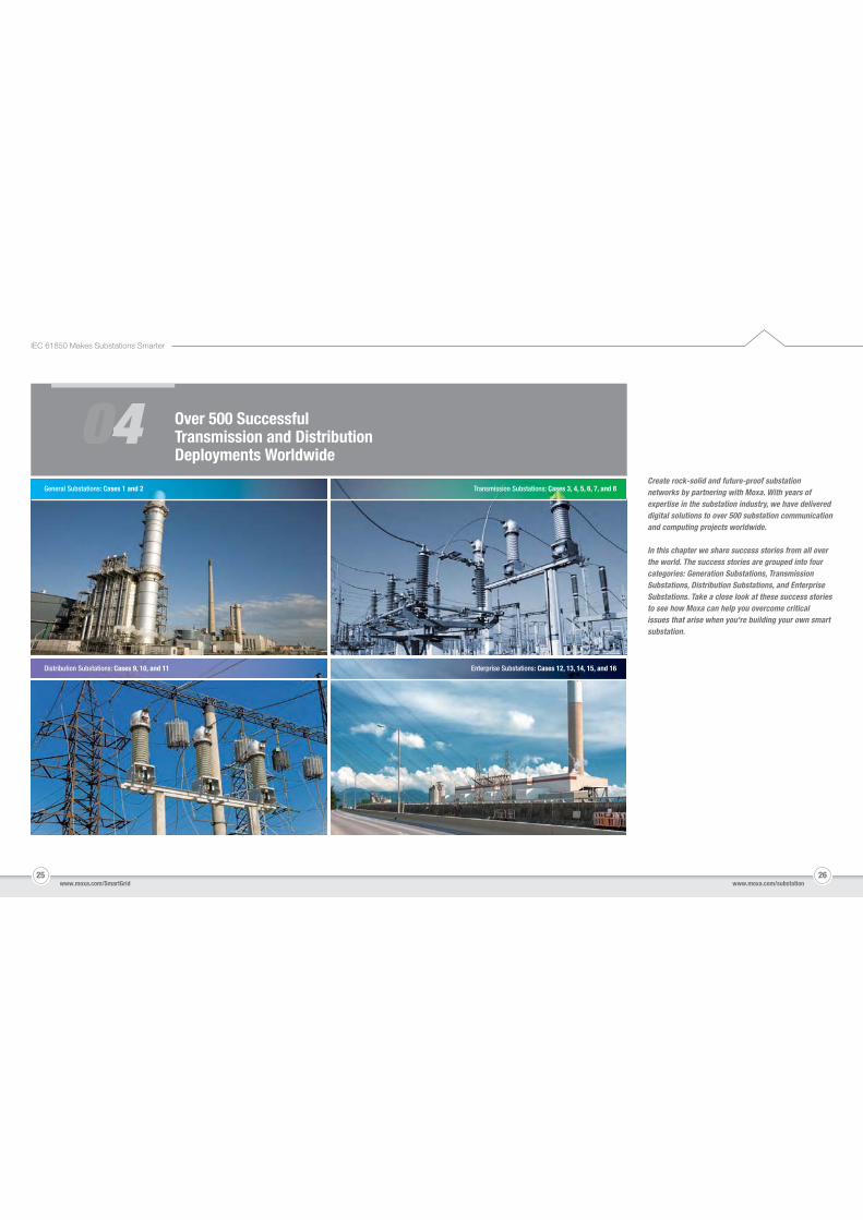
0400 Over 500 Successful Transmission and Distribution Deployments Worldwide
Create rock-solid and future-proof substation networks by partnering with Moxa. With years of expertise in the substation industry, we have delivered digital solutions to over 500 substation communication and computing projects worldwide.
In this chapter we share success stories from all over the world. The success stories are grouped into four categories: Generation Substations, Transmission Substations, Distribution Substations, and Enterprise Substations. Take a close look at these success stories to see how Moxa can help you overcome critical issues that arise when you're building your own smart substation.
Transmission Substations: Cases 3, 4, 5, 6, 7, and 8
Distribution Substations: Cases 9, 10, and 11
General Substations: Cases 1 and 2
Enterprise Substations: Cases 12, 13, 14, 15, and 16
27 28www.moxa.com/SmartGrid www.moxa.com/substation
IEC 61850 Makes Substations Smarter
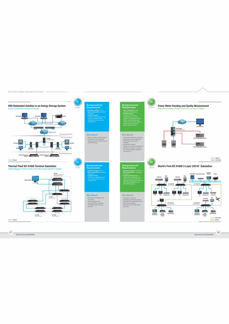
Background and Requirements
Substation Voltage: 345 kVType of Substation: Generation SubstationCustomer Needs: Implement ESS (Energy Storage System) to enable remote monitoring of the state of the energy stored
Why Moxa?Easy to configure HSR networkPT-G503 has one dedicated Ethernet port for monitoring and troubleshooting
Background andRequirements
Substation Voltage: 765 kVType of Substation: Generation SubstationCustomer Needs: Flexible port configuration with 4 fiber gigabit ports to form a redundant ring
Why Moxa?IEC 61850-3 and IEEE 1613 compliantTotal computing and communications solutionsPT-7528 provides the best CP ratio
Background and Requirements
Type of Substation: Utility Substation (Transmission)Customer Needs:A solution that can view measurements in real time, instead of by daily data uploads. Flexible and stable operation mode that can connect different types of devices. Protection against high EMS levels.
Why Moxa?Customized Firmware: Variety of operational modes supported5 Ethernet ports provideflexibility Customized Service: Support for specific certifications based on customer’s requests. For example, EMS certification up to level 4.
Background andRequirements
Substation Voltage: 110/220 kVType of Substation: Transmission SubstationCustomer Requirements:A state grid in Jiangsu province wants to build the world’s first digitized substation that utilizes the IEC 61850 GOOSE/SMV and IEEE 1588 standards.
Why Moxa?Consulting service for substation networking designPT-7728-PTP is IEC 61850-3 and IEEE 1613 compliantNanosecond level IEEE 1588 accuracy
Workstation Workstation Printeron on
Controller
Station SCADA
Controller
HMI HMI
PT-G503PRP/HSR RedBox
PT-7728Ethernet Switch
Modbus/TCP
HSR
Power Management System
Power Conversion System
Battery Management System
err CC
BBattery Management
System 1Battery Management
System 2
EDS-208A Ethernet Switch
EDS-208A Ethernet Switch
HSRHSR
Server Server
PT-7728Ethernet Switch
PT-7728Ethernet Switch
DA-683Data Concentrator withRedundant Servers
Switchgear Switchgear
Switchgear
NPort S8455ISerial Device Server
Power Quality Measurement
Network
Power Quality Measurement
PT-7728-PTPEthernet Switch
PT-7728-PTPEthernet Switch
PT-7728-PTPEthernet Switch
PT-7728-PTPEthernet Switch
SCADA/HMI
Protection
Protection
ProtectionGPS
MeterProtection
Meter
PrinterNetworkAnalyzerTelecommunication
ProtectionIED
IED
IED Merging Unit
IntelligentControl Unit
110 kV Protection
Relay
Fault RecorderIntelligentControl Unit
110 kV Protection
Relay
Fault Recorder
IED IED IEDMerging Unit Merging Unit
HSR Redundant Solution in an Energy Storage SystemPower Conversion System in Korea
Power Meter Reading and Quality MeasurementRetrofit Substation Project Wins with the NPort S8000
Thermal Plant IEC 61850 Terminal SubstationIndia’s Biggest Thermal Plant with Redundant Network Design
World’s First IEC 61850 3-Layer 220 kV Substation
Ethernet RS-232/485
Ethernet
Ethernet
Optical Fiber
Ethernet
Switchgear
Metering Metering
S it hSwitchgear SwitchgeaS it h r
KoreaKorea
India
ent System
India
FrancePR
France
China WChina
01001
02002
03003
04004
DA-710Communication Gateway
PT-7728IEC 61850-3Ethernet Switches
DA-820Communication Gateway
ioLogik E2214-TSmart Ethernet Remote I/O
Gateway A
IED Relay
MonitoringSystem
Local HMIGateway B
PT-7728-PTPEthernet Switch
29 30www.moxa.com/SmartGrid www.moxa.com/substation
IEC 61850 Makes Substations Smarter
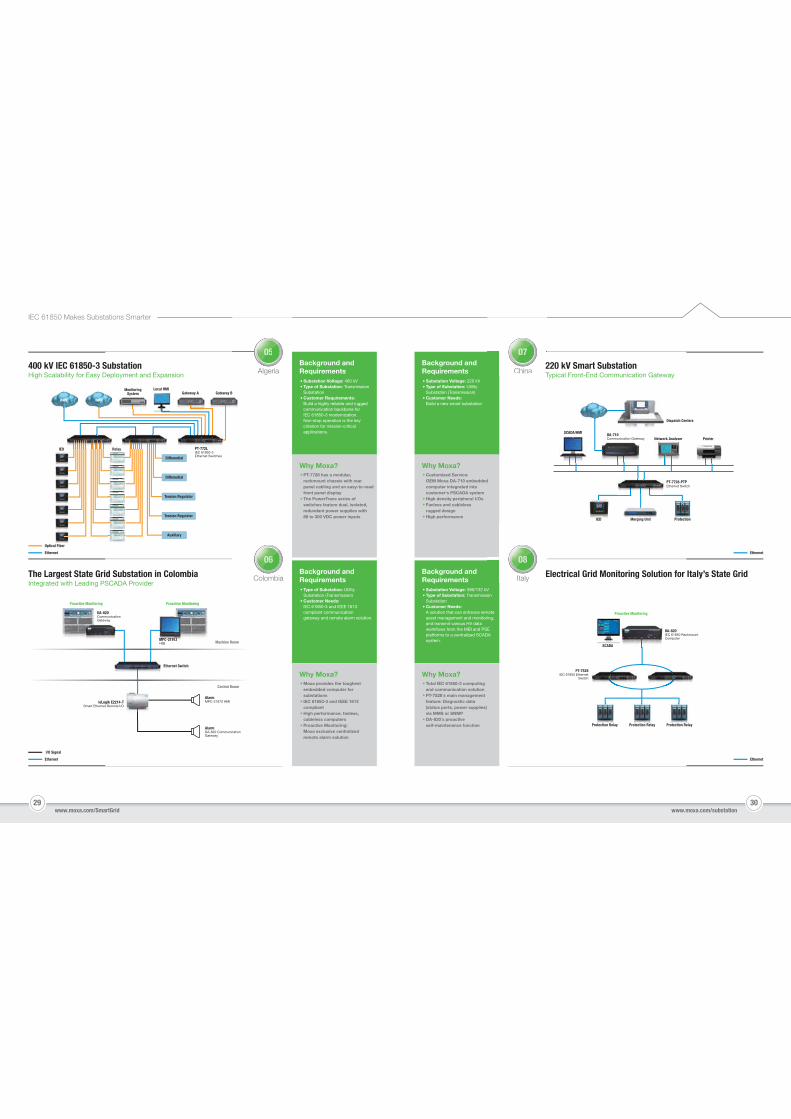
Background andRequirements
Substation Voltage: 400 kVType of Substation: Transmission SubstationCustomer Requirements:Build a highly reliable and rugged communication backbone for IEC 61850-3 modernization. Non-stop operation is the key criterion for mission-critical applications.
Why Moxa?PT-7728 has a modular, rackmount chassis with rear panel cabling and an easy-to-readfront panel displayThe PowerTrans series of switches feature dual, isolated, redundant power supplies with 88 to 300 VDC power inputs
Background andRequirements
Type of Substation: Utility Substation (Transmission)Customer Needs:IEC 61850-3 and IEEE 1613 compliant communication gateway and remote alarm solution.
Why Moxa?Moxa provides the toughest embedded computer for substationsIEC 61850-3 and IEEE 1613 compliantHigh performance, fanless, cableless computersProactive Monitoring: Moxa exclusive centralized remote alarm solution
Background andRequirements
Substation Voltage: 220 kVType of Substation: Utility Substation (Transmission)Customer Needs: Build a new smart substation
Why Moxa?Customized Service: OEM Moxa DA-710 embedded computer integrated into customer's PSCADA systemHigh density peripheral I/OsFanless and cablelessrugged designHigh performance
Background andRequirements
Substation Voltage: 380/132 kVType of Substation: Transmission SubstationCustomer Needs: A solution that can enhance remote asset management and monitoring, and transmit various HV data workflows from the MBI and PSE platforms to a centralized SCADA system.
Why Moxa?Total IEC 61850-3 computing and communication solutionPT-7528´s main management feature: Diagnostic data (status ports, power supplies) via MMS or SNMPDA-820´s proactiveself-maintenance function
PT-7728
WANWAN
Differential
Tension Regulator
Auxiliary
Differential
Tension Regulator
MPC-2197ZHMI Machine Room
Control Room
Ethernet Switch
MPC-2197MMPC 2197MMPMMPC 2197MPC 2197MPC-219777777ZZZZZHMI
SCADA/HMI
Network Analyzer Printer
DA-820IEC 61850 RackmountComputer
PT-7528IEC 61850 Ethernet
Switch
400 kV IEC 61850-3 SubstationHigh Scalability for Easy Deployment and Expansion
220 kV Smart SubstationTypical Front-End Communication Gateway
The Largest State Grid Substation in ColombiaIntegrated with Leading PSCADA Provider
Electrical Grid Monitoring Solution for Italy’s State Grid
I/O Signal
Ethernet
Optical Fiber
Ethernet
Ethernet Ethernet
Dispatch Centers
IED Merging Unit
Protection Relay Protection Relay Protection Relay
Protection
AlgeriaAlgeria
ColombiaColombia
China2T
China
Italy EItaly
050005
060006
070007
080008
SCADA
Proactive Monitoring
Proactive MonitoringProactive Monitoring
Alarm MPC-2197Z HMI
Alarm DA-820 Communication Gateway
31 32www.moxa.com/SmartGrid www.moxa.com/substation
IEC 61850 Makes Substations Smarter
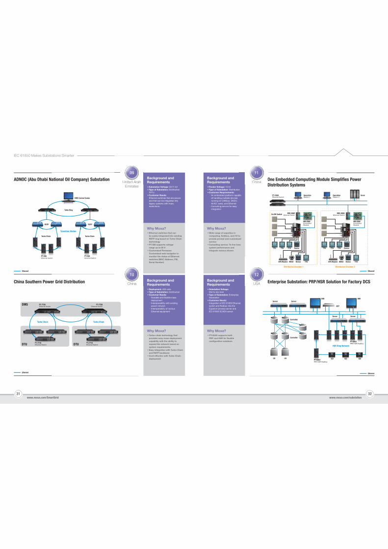
Background andRequirements
Substation Voltage: 33/11 kVType of Substation: Distribution FRTUCustomer Needs: Ethernet switches that are secure and that can be integrated into legacy systems with many restrictions.
Why Moxa?
Why Moxa?
Background andRequirements
Deployment: 400 unitsType of Substation: DistributionCustomer Needs:‧Scalable and flexible mass deployment‧Interoperability with existing power network‧Interoperability of various Ethernet equipment
Turbo Ring
Turbo Chain
RSTP
Turbo Chain
RSTP
PT-508Ethernet Switch
PT-508Ethernet Switch
Transition Station
DMS Control Center
ADNOC (Abu Dhabi National Oil Company) Substation One Embedded Computing Module Simplifies Power Distribution Systems
Ethernet Ethernet
Ethernet
PT-7710Ethernet Switch
PT-7710Ethernet Switch
Ethernet
Background andRequirements
Substation Voltage: Mid to low levelType of Substation: Enterprise Substation Customer Needs: Integration of IEC 61850 Ethernet switch and Redbox into the Experion process server and IEC 61850 SCADA server
Why Moxa?PT-G503 supports both PRP and HSR for flexible configuration solutions
Enterprise Substation: PRP/HSR Solution for Factory DCSChina Southern Power Grid Distribution
HMIHMIServer Server
Server Server
HSR Ring Network
NTP
Controller
Controller
I/O I/O IED IED IEDPT-G503PRP/HSR RedBox
PT-G503PRP/HSR RedBox
Background andRequirements
Feeder Voltage: 10 kVType of Substation: DistributionCustomer Requirements:‧An embedded platform capable of handling multiple devices running on CANbus, DI/DO, AI/AO, serial, and Ethernet‧Consulting service for easy integration
Why Moxa?Ethernet switches that can be easily integrated into existing RSTP ring based on Turbo Chain technology PT-508 supports voltage range up to 60 VCustomized Firmware: Customized web navigator to monitor the status of Ethernet switches (MAC Address, FW, Serial Number)
SeverPT-7828Ethernet Switch
EDS-508AEthernet Switch
EDS-508AEthernet SwitchOn/Off Switch
OperationStation 1
OperationStation 2
TTUDeviceMeterGPS Modem TTUDeviceMeterGPS Modem
EM-2260Embedded Module
EM-2260Embedded Module
Distribution Chamber 1 Distribution Chamber 2
TTU TTU DeviceTTU TTU TTU DeviceTTU
United ArabEmirates
United Arab
ChinaChina
ChinaOD
China
USA EUSA
09009
10110
11111
12112
Turbo-chain technology that provides easy mass-deployment capability with the ability to expand the network based on system requirements. Easy integration with Turbo Chain and RSTP backboneCost-effective with Turbo Chain deployment
Wide range of expertise in computing, fieldbus, and I/O to provide prompt and customized serviceConsulting service: To fine tune system performance and integrate various drivers
PT-7728Ethernet Switch
PT-7728Ethernet Switch
PT-7710 PT-7710
DMS
DTU DTU
Turbo Chain Turbo Chain
33 34www.moxa.com/SmartGrid www.moxa.com/substation
IEC 61850 Makes Substations Smarter
Background andRequirements
Why Moxa?Total computing, serial-to-Ethernet communication, and protocol conversion gateway solutionsConsulting serviceCustomized service: Value-added software libraries and APIs, with easy access to consultant services
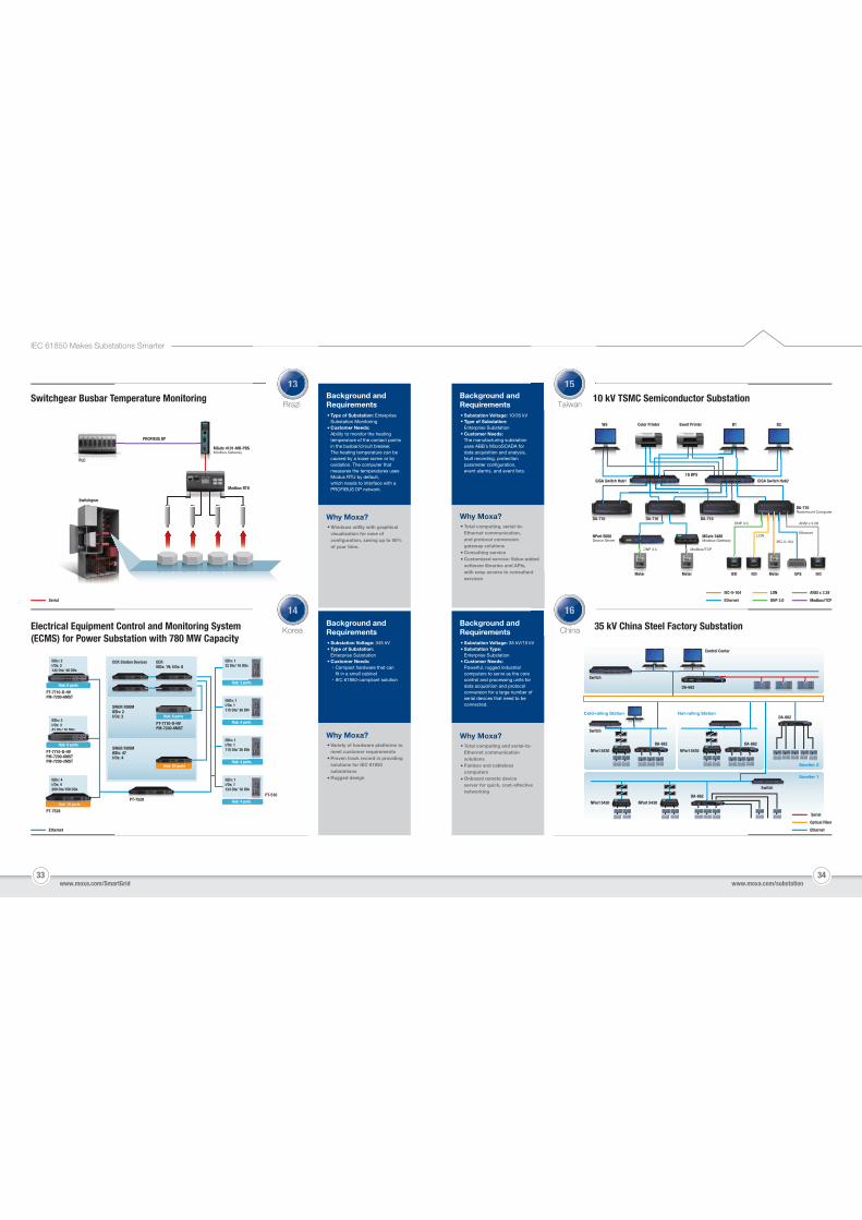
10 kV TSMC Semiconductor Substation
Ethernet
IEC-5-104
DNP 3.0
LON
Modbus/TCP
ANSI x 3.28
WS Color Printer
GIGA Switch Hub1 GIGA Switch Hub2
Event Printer
1G BPS
B1 B2
NPort 5600Device Server
MGate 3480Modbus Gateway
DNP 3.0
DNP 3.0 ANSI x 3.28
LONEthernet
IEC-5-104
Modbus/TCPDNP 3 0 Modbu
DA-710 DA-710 DA-710
DA-710Rackmount Computer
Meter Meter MeterIED IED UPS IEDMeterMeterMeter
Electrical Equipment Control and Monitoring System (ECMS) for Power Substation with 780 MW Capacity
Ethernet
Background andRequirements
Substation Voltage: 345 kVType of Substation: Enterprise SubstationCustomer Needs:
Compact hardware that can fit in a small cabinet
IEC 61850-compliant solution
Why Moxa?Variety of hardware platforms to meet customer requirementsProven track record in providing solutions for IEC 61850 substationsRugged design
IEDs: 2I/Os: 2142 DIs/ 40 DOs
CCR Station Devices
SWGR ROOMIEDs: 2I/Os: 2
SWGR ROOMIEDs: 47I/Os: 4
ECRIEDs: 19; I/Os: 8
Hub: 53 ports
PT-7710-D-HVPM-7200-6MST
PT-7710-D-HVPM-7200-6MST
PT-7710-D-HVPM-7200-6MSTPM-7200-2MST
PT-7528
IEDs: 4I/Os: 4200 DIs/150 DOs
Hub: 10 ports
IEDs: 132 DIs/ 16 DOs
Hub: 3 ports
IIEDs: 1I/Os: 1115 DIs/ 36 DOs
Hub: 4 ports
IEDs: 1I/Os: 1115 DIs/ 36 DOs
Hub: 4 ports
IEDs: 1I/Os: 1124 DIs/ 18 DOs
Hub: 4 portsHub: 10 ports
IEDs: 3I/Os: 343 DIs/ 10 DOs
Hub: 53 ports
Hub: 6 ports
Hub: 8 ports
Hub: 6 ports
PT-7528PT-510
Background andRequirements
Substation Voltage: 35 kV/10 kVSubstation Type:Enterprise SubstationCustomer Needs:Powerful, rugged industrial computers to serve as the core control and processing units for data acquisition and protocol conversion for a large number of serial devices that need to be connected.
Why Moxa?Total computing and serial-to-Ethernet communication solutionsFanless and cableless computersOnboard remote device server for quick, cost-effective networking
Switch
Control Center
DA-662
DA-662
DA-662
DA-662
NPort 5430
NPort 5430 NPort 5430
NPort 5430
DA-662
35 kV China Steel Factory Substation
Ethernet
Optical Fiber
Serial
Smelter 1
Smelter 2
Hot-rolling StationCold-rolling Station
Switch
Switch
Serial
MGate 4101-MB-PBS Modbus Gateway
PLC
Modbus RTU
Switchgear
PROFIBUS DP
Switchgear Busbar Temperature Monitoring Background andRequirements
Type of Substation: Enterprise Substation MonitoringCustomer Needs: Ability to monitor the heating temperature of the contact points in the busbar/circuit breaker. The heating temperature can be caused by a loose screw or by oxidation. The computer that measures the temperatures uses Modus RTU by default, which needs to interface with a PROFIBUS DP network.
Why Moxa?Windows utility with graphical visualization for ease of configuration, saving up to 50% of your time.
BrazilBrazil
KoreaKorea
Taiwan1
Taiwan
China
nt
3China
131113
141114
1511115
161116
Substation Voltage: 10/35 kVType of Substation: Enterprise SubstationCustomer Needs:The manufacturing substation uses ABB´s MicroSCADA for data acquisition and analysis, fault recording, protection parameter configuration, event alarms, and event lists.
ts
s
ts
s
ts
s
ts
35 36www.moxa.com/SmartGrid www.moxa.com/substation
IEC 61850 Makes Substations Smarter
Product Selection Guide
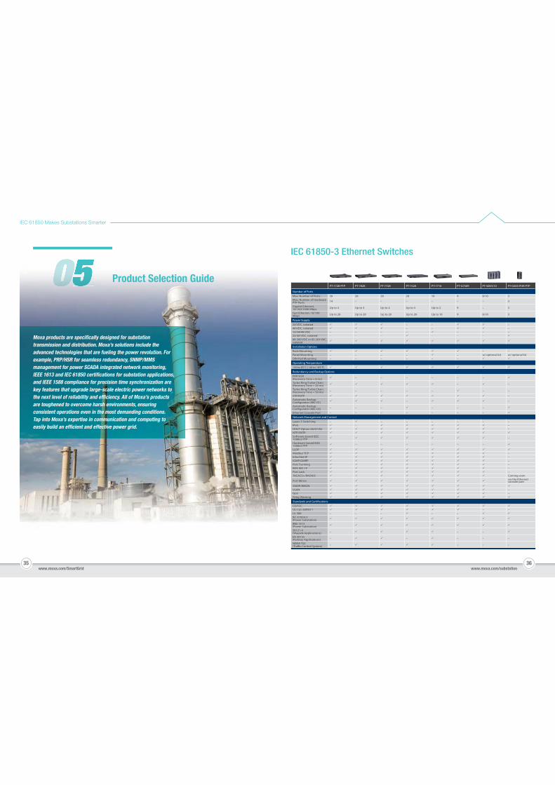
Moxa products are specifically designed for substation transmission and distribution. Moxa’s solutions include the advanced technologies that are fueling the power revolution. For example, PRP/HSR for seamless redundancy, SNMP/MMS management for power SCADA integrated network monitoring, IEEE 1613 and IEC 61850 certifications for substation applications, and IEEE 1588 compliance for precision time synchronization are key features that upgrade large-scale electric power networks to the next level of reliability and efficiency. All of Moxa’s products are toughened to overcome harsh environments, ensuring consistent operations even in the most demanding conditions. Tap into Moxa’s expertise in communication and computing to easily build an efficient and effective power grid.
PT-7728-PTP PT-7828 PT-7728 PT-7528 PT-7710 PT-G7509 PT-508/510 PT-G503-PHR-PTP
Number of Ports
Max. Number of Ports 28 28 28 28 10 9 8/10 3Max. Number of Hardware PTP Ports 14 – – – – – – 3
Gigabit Ethernet, 10/100/1000 Mbps Up to 4 Up to 4 Up to 4 Up to 4 Up to 2 9 – 3
Fast Ethernet, 10/100 Mbps Up to 28 Up to 28 Up to 28 Up to 28 Up to 10 9 8/10 3
Power Supply
24 VDC, isolated – – –48 VDC, isolated – – –12/24/48 VDC – – – – – – –24/48 VDC, isolated – – – – – –88-300 VDC or 85-264 VAC, isolated
Installation Options
Rack Mounting – –Panel Mounting – – – – – w/ optional kit w/ optional kitDIN-Rail Mounting – – – – – –
Operating Temperature
-40 to 85°C (-40 to 185°F)
Redundancy and Backup Options
PRP/HSR (Recovery Time ≈ 0 ms) – – – – – –
Turbo Ring/Turbo Chain (Recovery Time < 20 ms) – –
Turbo Ring/Turbo Chain (Recovery Time < 50 ms) – – – – – – –
STP/RSTP –Automatic Backup – –
Automatic Backup – – – – – –
Ethernet Console Port – – – – – – –
Network Management and Control
Layer-3 Switching – – – – – – –IPv6 – –DHCP Option 66/67/82 –NTP/SNTPSoftware-based IEEE 1588v2 PTP –
Hardware-based IEEE 1588v2 PTP – – – – – –
LLDPModbus TCP –EtherNet/IP –IGMP/GMRP –Port Trunking –IEEE 802.1X –Port Lock –TACACS+/RADIUS Coming soon
Port Mirror via the Ethernet console port
SNMP/RMONVLAN –QoS –Relay Warning
CE/FCCUL/cUL 60950-1 – –UL 508 – – – – –IEC 61850-3 (Power Substation)IEEE 1613 (Power Substation)50121-4 (Wayside Applications) – – –
EN 50155 (Railway Applications) – – – – –
NEMA TS2 – – – –
IEC 61850-3 Ethernet Switches
37 38
IEC 61850 Makes Substations Smarter
www.moxa.com/SmartGrid www.moxa.com/substation
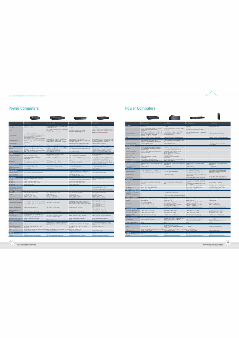
Power Computers Power Computers
DA-820 Series DA-682A Series DA-681A Series DA-683 Series
Computer
CPU Speed 2.5 GHz/2.1 GHz 1.4 GHz single core/1.1 GHz dual core/ 1.5 GHz dual core 1.4 GHz 1.66 GHz
OS –Linux Debian 7 or Windows Embedded Standard 7Note: The OS is pre-installed.
Linux Debian 8 (pre-installed)Note: W7E available by CTOS
Linux, Windows Embedded Standard 2009, or Windows Embedded Standard 7Note: The OS is pre-installed.
OS (Optional)64-bit Linux Debian 7 64-bit Windows Embedded Standard 7 64-bit Windows 7 Professional for embedded systems
– – –
System MemoryMax. 16 GB capacity (204-pin SO-DIMM
DDR3 memory at 1333 and 1600 MT/s, 8 GB Max.)
8 GB capacity, 1 GB (LX) / 2 GB (W7E) pre-installed: 1 slot of 4 GB DDR3-1066/1333 SO-DIMM SDRAM
8 GB capacity, 2 GB for Linux pre-installed; 1 slot of DDR3-1066/1333 SO-DIMM SDRAM
2 GB capacity, 1 GB (LX and XPE)/ 2 GB (W7E) pre-installed: 1 or 2 slots of 2 GB 200-pin DDR2-667 SO-DIMM
Expansion Bus – – PCI/104 onboard (DPP models only) PCI/104 interface reservedUSB USB 2.0 hosts x 6, type A connector USB 2.0 hosts x 2, type A connector USB 2.0 hoss x 4, type A connector USB 2.0 hosts x 4, type A connectorStorage
Built-in CFast socket: Optional Cfast card to store OS
2 GB (LX) / 8 GB (W7E) industrial DOM for read-only OS volume 8 GB for Linux (pre-installed in mSATA) 2 GB (LX and XPE) / 8 GB (W7E)
industrial DOM onboard to store OS
Storage Expansion 4 SATA 2.0 interfaces, supporting RAID 0, 1, 5, 10, hot-swappable
• 1 x CompactFlash socket • 2 x SATA-300 connector SATA 3.0 interface CompactFlash socket for CF card
expansion, supporting CF Type-I/IIDisplay
Graphics Controller Intel® HD Graphics 4000 Intel 915GME, and Intel Extreme Graphics 2 technology Intel® HD Graphics (Integrated) Intel® GMA3150 graphics controller in
Intel D510 card
Display Interface 2 VGA outputs (DB15 female connector) 1 VGA output (DB15 female connector) 1 VGA output (DB15 female connector) Analog RBG display/Digital DVI display
Resolution CRT display mode with pixel resolution up to 2048 x 1536 at 75 Hz
CRT display mode with pixel resolution up to 2548 x 1536 at 75 Hz
CRT display mode with pixel resolution up to 2048 x 1536 at 75 Hz
• Analog RBG display; output resolution up to 2048 x 1536 @ 60 Hz • Digital DVI display; output resolution up to 1024 x 768 @ 60 Hz
Ethernet InterfaceLAN 10/100/1000 Mbps ports x 4 10/100/1000 Mbps ports x 6 10/100/1000 Mbps ports x 6 10/100/1000 Mbps ports x 6Magnetic Isolation Protection 1.5 kV built-in 1.5 kV built-in 1.5 kV built-in 1.5 KV built-in
Serial Interface
Serial Standards 2 RS-232/422/485 ports (DB9 male) – • 2 RS-232/422/485 ports (DB9 male) • 10 RS-485 ports (terminal block) 2 RS-232 ports (DB9 male)
ESD Protection – – 15 kV for all signals –Surge Protection – – 4 kV (DA-681A-I-DPP Series) –Serial Signals
RS-232 TxD, RxD, DTR, DSR, RTS, CTS, DCD, GND – TxD, RxD, DTR, DSR, RTS, CTS, DCD, GND TxD, RxD, DTR, DSR, RTS, CTS, DCD,
GND, RIRS-422 TxD+, TxD-, RxD+, RxD-, GND – TxD+, TxD-, RxD+, RxD-, GND –RS-485-4w TxD+, TxD-, RxD+, RxD-, GND – TxD+, TxD-, RxD+, RxD-, GND –RS-485-2w Data+, Data-, GND – Data+, Data-, GND –Digital Input/Digital OutputInput/Output Channels – – – 4, source type/4, sink typeInput Voltage/Output Current – – – 0 to 30 VDC/200 mA per channel max.
Physical CharacteristicsHousing SECC sheet metal (1 mm) SECC sheet metal (1 mm) SECC sheet metal (1 mm) SECC sheet metal (1 mm)Weight 14 kg (31.11 lb) 7 kg (15.56 lb) 4.5 kg (10 lb) 4 kg (8.89 lb)
Dimensions361 x 440 x 133 mm (14.23 x 17.32 x 5.24 in) (without rackmount ears)
440 x 315 x 90 mm (17.32 x 12.40 x 3.54 in) (without rackmount ears)
440 x 315 x 45 mm (17.32 x 12.40 x 1.77 in), 19 inch 1U height
315 x 440 x 90 mm (12.40 x 17.32 x 3.54 in) (without rackmount ears)
Environmental Limits
Operating Temperature • DA-820-C8: -40 to 60°C (-40 to 140°F) • DA-820-C7: -40 to 75 °C (-40 to 167°F) -10 to 60°C (14 to 140°F)
SP Models: -25 to 55°C (-13 to 131°F) DPP Models: -25 to 55°C (-13 to 131°F) DPP-T Models: -40 to 70°C (-40 to 158°F)
Standard models: -10 to 60°C (14 to 140°F) DPP-T models: -40 to 70°C (-40 to 158°F)
Storage Temperature -40 to 85°C (-40 to 185°F) -20 to 80°C (-4 to 176°F) -40 to 85°C (-40 to 185°F)Standard models: -20 to 80°C (-4 to 176°F) DPP-T models: -40 to 85°C (-40 to 185°F)
Ambient Relative Humidity 5 to 95% (non-condensing) 5 to 95% (non-condensing) 5 to 95% (non-condensing) 5 to 95% (non-condensing)
Power Requirements
Input Voltage• High Voltage: 100 to 240 VAC/VDC, 50/60 Hz, 1 A • Low Voltage: 24 to 110 VDC, 4.7 A
100 to 240 VAC auto-ranging (47 to 63 Hz for AC input) 100 to 240 VAC; 100 to 240 VDC 100 to 240 VAC, 50/60 Hz, 0.9-0.4 A
Multiple Power Supplies Single /Dual power supplies – Single / Dual power supplies Single / Dual power suppliesPower Consumption 60 W 30 W (full loading) 25 W 40 W
Safety LVD, UL, cULUL 60950-1, CSA C22.2 No. 60950-1-03, EN 60950-1, CCC (GB4943, GB9254, GB17625.1)
UL 60950-1, IEC 60950-1, EN 60950-1UL/cUL (UL 60950-1, CSA C22.2 No. 60950-1-03), LVD (EN 60950-1), CCC (GB4943)
Electrical Substation IEC 61850-3, IEC 60255, IEEE 1613 – IEC 61850-3, IEEE 1613, IEC 60255 IEC 61850-3, IEEE 1613 Protection Relay IEC 60255 – IEC 60255 –EMS IEC 61000-4-2, IEC 61000-4-3, IEC 61000-4-4, IEC 61000-4-5, IEC 61000-4-6, IEC 61000-4-8, IEC 61000-4-11Green Product RoHS, CRoHS, WEEE RoHS, CRoHS, WEEE RoHS, CRoHS, WEEE RoHS, CRoHS, WEEEWarrantyWarranty Period 3 years 3 years 3 years 3 yearsDetails See www.moxa.com/warranty See www.moxa.com/warranty See www.moxa.com/warranty See www.moxa.com/warranty
DA-685 Series DA-710 Series DA-662A Series UC-8100 Series
ComputerCPU Speed 1.66 GHz 2.2 GHz 500 MHz 300/600/1000 MHz
OSLinux, Windows Embedded Standard 2009, or Windows Embedded Standard 7
Windows Embedded Standard 2009, Linux 2.6 Embedded Linux (pre-installed) –
System Memory2 GB capacity, 1 GB (LX and XPE)/ 2 GB (W7E) pre-installed: 1 or 2 slots of 2 GB 200-pin DDR2-667 SO-DIMM
2 GB capacity, 1 GB pre-installled: 1 slot of DDR2-533/667 200-pin SO-DIMM SDRAM
128 MB DRAM onboard, 32 MB Flash onboard 256 or 512 MB DDR3 SDRAM
Expansion Bus PCI/104 interface reserved –– –USB USB 2.0 hosts x 2, type A connector USB 2.0 hosts x 4, type A connector – USB 2.0 hosts x 1, type A connectorStorage
Built-in 2 GB (LX and XPE) / 8 GB (W7E) industrial DOM onboard to store OS
2 GB industrial DOM onboard to store OS – –
Storage Expansion CompactFlash socket CompactFlash socket – 1 GB SD or 2 GB MicroSD card pre-installed
Other Peripherals
KB/MS1 PS/2 interface, supports standard PS/2 keyboard and mouse through Y-type cable
1 PS/2 interface, supports standard PS/2 keyboard and PS/2 mouse – –
Graphics Controller Intel® GMA3150 graphics controller on Intel D510 card
Integrated Intel graphics media accelerator (GMA X3100) – –
Intel Clear Video Technology
MPEG-2 hardware accelerator, Microsoft DirectX 9 –– –
Display Interface 1 VGA output (DB15 female connector)
1 VGA output (DB15 female connector) – –
Resolution CRT display mode with pixel resolution up to 2048 x 1536 at 75 Hz
QXGA maximum with resolution up to – –
Ethernet Interface
LAN Auto-sensing 10/100/1000 Mbps ports x 6
Auto-sensing 10/100/1000 Mbps ports (RJ45) x 4
Auto-sensing 10/100 Mbps ports (RJ45) x 4
Auto-sensing 10/100 Mbps ports (RJ45) x 2
Magnetic Isolation Protection 1.5 kV built-in 1.5 kV built-in 1.5 kV built-in 1.5 kV built-in
Serial Interface
Serial Standards • 2 RS-232/422/485 ports (DB9 male) • 6 RS-485-2W ports (terminal block) 2 RS-232 ports (DB9 male) 8 to 16 RS-232/422/485 ports,
software selectable (8-pin RJ45)RS-232/422/485 ports, software-selectable (5-pin terminal block connector) x 1 or 2
ESD Protection – –4 kV for all signals 8 kV contact, 15 kV Air ESD protection for all signals
Console Port – – RS-232 (all signals), RJ45 connector RS-232 (TxD, RxD, GND), 4-pin pin header output (115200, n, 8, 1)
Serial Signals
RS-232 TxD, RxD, DTR, DSR, RTS, CTS, DCD, GND, RI
TxD, RxD, DTR, DSR, RTS, CTS, DCD, GND
TxD, RxD, DTR, DSR, RTS, CTS, DCD, GND (DA-662A-I-8/16-LX only: TxD, RxD, RTS, CTS, GND)
TxD, RxD, RTS, CTS, GND
RS-422 TxD+, TxD-, RxD+, RxD-, GND – TxD+, TxD-, RxD+, RxD-, GND TxD+, TxD-, RxD+, RxD-, GNDRS-485-4w TxD+, TxD-, RxD+, RxD-, GND – TxD+, TxD-, RxD+, RxD-, GND TxD+, TxD-, RxD+, RxD-, GNDRS-485-2w Data+, Data-, GND – Data+, Data-, GND Data+, Data-, GNDDigital Input/Digital OutputInput Channel/Output Channel – 4, source type/4, sink type – –
Input Voltage/Output Current – 0 to 30 VDC/max. 200 mA per channel – –
Physical CharacteristicsHousing SECC sheet metal (1 mm) SECC sheet metal (1 mm) SECC sheet metal (1 mm) Polycarbonate plasticWeight 4 kg (8.89 lb) 14 kg (31.11 lb) 4.3 kg (9.56 lb) 224 g (0.50 lb)
Dimensions315 x 440 x 90 mm (12.40 x 17.32 x 3.54 in) (without rackmount ears)
• Without ears: 400 x 420 x 180 mm (15.75 x 16.54 x 7.09 in) • With ears: 400 x 480 x 180 mm (15.75 x 18.90 x 7.09 in)
Without ears: 440 x 45 x 237 mm (17.32 x 1.77 x 9.33 in) With ears: 480 x 45 x 237 mm (18.90 x 1.77 x 9.33 in)
101 x 27 x 128 mm (3.98 x 1.06 x 5.04 in)
Mounting Standard 19-inch rackmount Standard 19-inch rackmount Standard 19-inch rackmount DIN-rail, wall (with optional kit)Environmental Limits
Operating Temperature -10 to 55°C (14 to 131°F) -10 to 50°C (14 to 122°F) -10 to 60°C (14 to 140°F) -10 to 60°C (14 to 140°F) or -40 to 75°C (-40 to 167°F)
Storage Temperature -20 to 80°C (-4 to 176°F) -20 to 80°C (4 to 176°F) -20 to 80°C (-4 to 176°F) -40 to 80°C (-40 to 176°F)Ambient Relative Humidity 5 to 95% (non-condensing) 5 to 95% (non-condensing) 5 to 95% (non-condensing) 5 to 95% (non-condensing)
Power Requirements
Input Voltage 100 to 240 VAC, 50/60 Hz, 0.9-0.4 ASingle or dual inputs, 100 to 240 VAC/VDC auto-ranging, 47 to 63 Hz, terminal block
100 to 240 VAC auto ranging (47 to 63 Hz for AC input)
12 to 24 VDC (3-pin terminal block, V+, V-, SG)
Power Consumption 40 W 60 W 20 W 5.4 W
Safety LVD, UL, cUL, CCCUL 60950-1, CSA C22.2 No. 60950-1-07, CCC (GB4943, GB9254, GB17625.1)
UL 60950-1 UL 60950-1, EN 60950-1
EMS IEC 61000-4-2, IEC 61000-4-3, IEC 61000-4-4, IEC 61000-4-5, IEC 61000-4-6, IEC 61000-4-8, IEC 61000-4-11 –Green Product RoHS, CRoHS, WEEE RoHS, CRoHS, WEEE RoHS, CRoHS, WEEE RoHS, CRoHS, WEEEWarrantyWarranty Period 3 years 3 years 5 years 5 yearsDetails See www.moxa.com/warranty See www.moxa.com/warranty See www.moxa.com/warranty See www.moxa.com/warranty
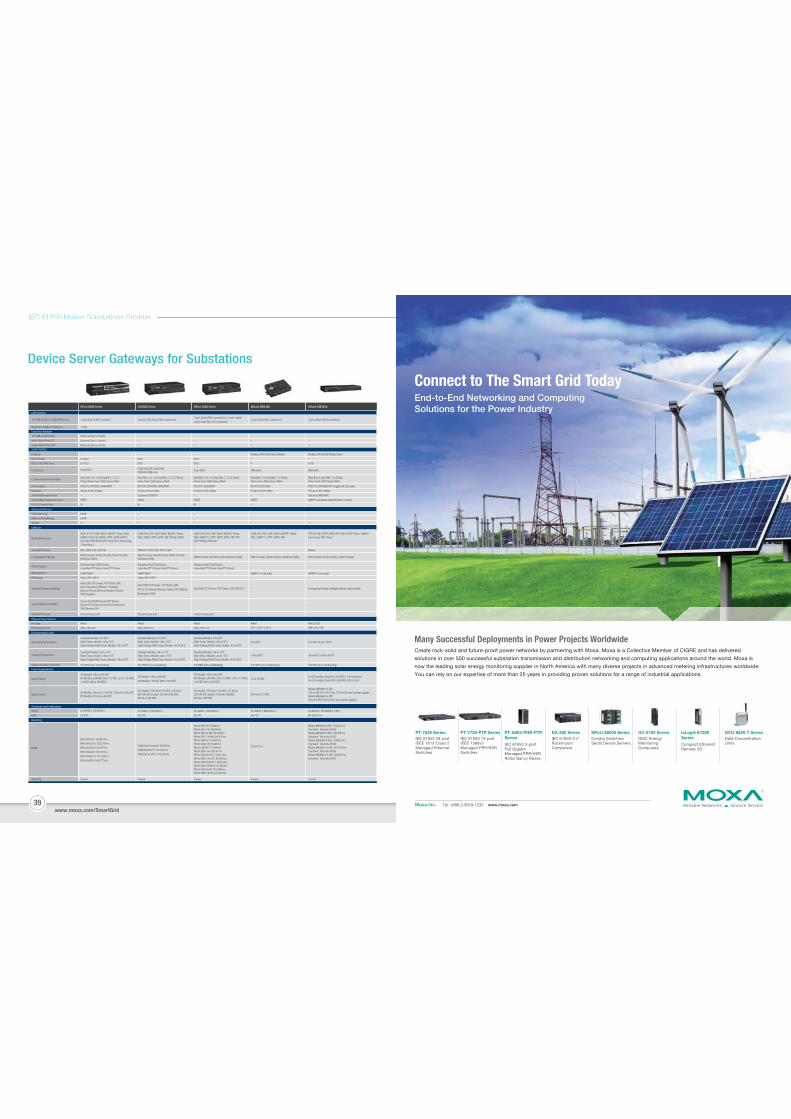
39
IEC 61850 Makes Substations Smarter
www.moxa.com/SmartGrid
Device Server Gateways for Substations
Reliable Networks Sincere ServiceMoxa Inc. Tel: +886-2-8919-1230 www.moxa.com
Many Successful Deployments in Power Projects WorldwideCreate rock-solid and future-proof power networks by partnering with Moxa. Moxa is a Collective Member of CIGRE and has delivered
solutions in over 500 successful substation transmission and distribution networking and computing applications around the world. Moxa is
now the leading solar energy monitoring supplier in North America with many diverse projects in advanced metering infrastructures worldwide.
You can rely on our expertise of more than 25 years in providing proven solutions for a range of industrial applications.
www.moxa.com/SmartGrid
Connect to The Smart Grid TodayEnd-to-End Networking and Computing Solutions for the Power Industry
IEC 61850 28-port IEEE 1613 Class 2 Managed Ethernet Switches
PT-7528 Series
IEC 61850 3-port Full Gigabit Managed PRP/HSR Redundancy Boxes
PT-G503-PHR-PTP Series IEC 61850-3 i7
Rackmount Computers
DA-820 SeriesCombo Switches/Serial Device Servers
NPort S8000 SeriesRISC Energy Monitoring Computers
UC-8100 SeriesData Concentration Units
DCU-8620-T Series
Compact Ethernet Remote I/O
ioLogik E1200 SeriesIEC 61850 14-port
IEEE 1588v2 Managed PRP/HSR Switches
PT-7728-PTP Series
Expansion Modules10/100BaseT(X) (RJ45)Multi-Mode Fiber (SC)Single-Mode Fiber (SC)
Optional (Up to 2 ports)Optional (Up to 2 ports)Optional (Up to 2 ports)
–––
–––
–––
–––
Warranty
Serial Interface
ProtocolRS-232 PortsRS-232/422/485 Ports
Flow ControlBaudrate2 kV isolation protectionRS-485 Data Direction ControlRS-232 Console Port
Connectors
Communication Parameters
Serial Data LogOffline Port BufferingSD Slot
Standard Operation Modes
Software
Network Protocols
Security Protocols
Configuration Options
Driver Support
Management
IP Routing
HousingDimensions (mm)
Secure Operation Modes
Advanced Features
Terminal Sessions
Environmental Limits
Operating Temperature
Storage Temperature
Ambient Relative Humidity
Input Voltage
Power Requirements
Input Current
Standards and Certifications
Reliability
Physical Characteristics
SafetyEMC
MTBF
5 years
–
8/16/328/16/32
8-pin RJ45
Data Bits: 5, 6, 7, 8; Stop Bits: 1, 1.5, 2; Parity: None, Even, Odd, Space, Mark
RTS/CTS, DTR/DSR, XON/XOFF50 bps to 921.6 Kbps–ADDC
64 KB64 KB
ICMP, IP, TCP, UDP, DHCP, BOOTP, Telnet, DNS, SNMP V1/V2c/V3, DDNS, HTTP, SMTP, HTTPS, SSL, SSH, PPPoE, RFC2217, IPv6, IPv4, Turbo Ring, Turbo Ring 2
DES, 3DES, AES, SSH, SSL
Web Console, Telnet Console, Serial Console, Windows Utility
Windows Real COM Drivers,Linux Real TTY driver, Fixed TTY driver
SNMP MIB-IIStatic, RIP-I, RIP-II
Real COM, TCP Server, TCP Client, UDP, Pair Connection, RFC2217, Terminal, Reverse Telnet, Ethernet Modem, Printer, PPP, Disabled
Secure Real COM, Secure TCP Server, Secure TCP Client, Secure Pair Connection, SSH, Reverse SSH
8 sessions per port
Metal440 x 195 x 44
Standard Models: 0 to 55°CWide Temp. Models: -40 to 75°CHigh Voltage Wide Temp. Models: -40 to 85°C
Standard Models: -40 to 75°CWide Temp. Models: -40 to 75°CHigh Voltage Wide Temp. Models: -40 to 85°C
5 to 95% (non-condensing)
AC Models: 100 to 240 VACDC Models: ±48 VDC (20 to 72 VDC, -20 to -72 VDC), 110 VDC (88 to 300 VDC)
AC Models: 285 mA @ 100 VAC, 190 mA @ 240 VACDC Models: 293 mA @ 48 VDC
UL 60950-1, EN 60950-1CE, FCC
NPort 6610-8: 135,891 hrsNPort 6610-16: 102,373 hrsNPort 6610-32: 68,707 hrsNPort 6650-8: 135,370 hrsNPort 6650-16: 101,783 hrsNPort 6650-32: 68,177 hrs
5 years
–8/168/16
CN2610/2650: 8-pin RJ45CN2650I: DB9 male
Data Bits: 5, 6, 7, 8; Stop Bits: 1, 1.5, 2; Parity: None, Even, Odd, Space, Mark
RTS/CTS, DTR/DSR, XON/XOFF50 bps to 921.6 KbpsOptional (CN2650I)ADDC
–––
ICMP, IPv4, TCP, UDP, DHCP, BOOTP, Telnet,DNS, SNMP, HTTP, SMTP, ARP, PPPoE, DDNS
RADIUS, HTTPS, SSH, PAP, CHAP
Web Console, Serial Console, Telnet Console,Windows Utility
Windows Real COM Drivers,Linux Real TTY driver, Fixed TTY driver
SNMP MIB-IIStatic, RIP-I, RIP-II
Real COM, TCP Server, TCP Client, UDP, RFC2217,Terminal, Reverse Telnet, PPP, DRDAS, Redundant COM
– –
8 sessions per port
Metal440 x 195 x 44
Standard Models: 0 to 55°CWide Temp. Models: -40 to 75°CHigh Voltage Wide Temp. Models: -40 to 85°C
Standard Models: -40 to 75°CWide Temp. Models: -40 to 75°CHigh Voltage Wide Temp. Models: -40 to 85°C
5 to 95% (non-condensing)
AC Models: 100 to 240 VACDC Models: 110 VDC (88 to 300 VDC)
AC models: 235 mA @ 100 VAC, 145 mA @ 240 VAC DC models: 152 mA @ 88 VDC, 86 mA @ 300 VDC
UL 60950-1, EN 60950-1CE, FCC
CN2650I AC models: 99,320 hrsCN2650I-8-HV-T: 191,326 hrsCN2650I-16-HV-T: 116,924 hrs
5 years
–8/168/16
8-pin RJ45
Data Bits: 5, 6, 7, 8; Stop Bits: 1, 1.5, 2; Parity: None, Even, Odd, Space, Mark
RTS/CTS, XON/XOFF50 bps to 921.6 Kbps–ADDC
–––
–––
–––
ICMP, IPv4, TCP, UDP, DHCP, BOOTP, Telnet,DNS, SNMP V1, HTTP, SMTP, SNTP, ARP, PPP, SLIP, RTelnet, RFC2217
– –
Web Console, Telnet Console, Windows Utility
Windows Real COM Drivers,Linux Real TTY driver, Fixed TTY driver
––
Real COM, TCP Server, TCP Client, UDP, RFC2217
4 sessions per port
Metal440 x 195 x 44
Standard Models: 0 to 55°CWide Temp. Models: -40 to 75°CHigh Voltage Wide Temp. Models: -40 to 85°C
Standard Models: -40 to 75°CWide Temp. Models: -40 to 75°CHigh Voltage Wide Temp. Models: -40 to 85°C
5 to 95% (non-condensing)
AC Models: 100 to 240 VACDC Models: ±48 VDC (20 to 72 VDC, -20 to -72 VDC), 110 VDC (88 to 300 VDC)
AC models: 174 mA @ 100 VAC, 113 mA @ 240 VAC DC models: 152 mA @ 88 VDC, 86 mA @ 300 VDC
UL 60950-1, EN 60950-1CE, FCC
NPort 5610-8: 97,294 hrsNPort 5610-16: 94,928 hrsNPort 5610-8-48V: 96,758 hrsNPort 5610-16-48V: 94,417 hrsNPort 5630-8: 118,405 hrsNPort 5630-16: 91,483 hrsNPort 5650-8: 117,584 hrsNPort 5650-16: 104,767 hrsNPort 5650-8-S-SC: 116,914 hrsNPort 5650-16-S-SC: 87,528 hrsNPort 5650-8-M-SC: 116,914 hrsNPort 5650-16-M-SC: 87,528 hrsNPort 5650-8-HV: 725,390 hrsNPort 5650-16-HV: 531,264 hrs
5 years 5 years
Modbus RTU/ASCII Slave/Master–4
DB9 male
Data Bits: 7, 8; Stop Bits: 1, 2; Parity: None, Even, Odd, Space, Mark
RTS/CTS, DTR/DSR50 bps to 921.6 Kbps–ADDC–
ICMP, IPv4, TCP, UDP, DHCP, BOOTP, Telnet,DNS, SNMP V1, HTTP, SMTP, ARP
Web Console, Telnet Console, Windows Utility
– –
SNMP v1 (read only)– –
–
–
–
–
–
Metal35.5 x 102.7 x 157.2
5 to 95% (non-condensing)
0 to 60°C
-40 to 85°C
12 to 48 VDC
385 mA @ 12 VDC
UL 60950-1, EN 60950-1CE, FCC
295,812 hrs
RTS/CTS, DTR/DSR, RTS Toggle (RS-232 only)50 bps to 921.6 KbpsOptional (MB3660I)ADDC® (automatic data direction control)–
Modbus RTU/ASCII Master/Slave–8/16
DB9 male
Data Bits: 8; Stop Bits: 1, 2; Parity:None, Even, Odd, Space, Mark
TCP/IP, UDP, HTTP, SMTP, NTP, DNS, DHCP Client, SNMPv1 (read only), ARP, Telnet
Radius
Web console, Serial console, Telnet console
SNMPv1 (read only)
Transparant Mode, Intelligent Mode, Agent Mode
Metal, IP30440 x 45 x 198
5 to 95% (non-condensing)
0 to 60°C (32 to 140°F)
-40 to 85°C (-40 to 185°F)
For DC models: Dual 20 to 60 VDC (1.5 kV isolation)For AC models: Dual 100 to 240 VAC, 47 to 63 Hz
UL 60950-1, EN 60950-1 (LVD)EN 55022/24
MGate MB3660-8-2AC: 716,647 hrsStandard: Telcordia SR332MGate MB3660-8-2DC: 706,783 hrsStandard: Telcordia SR332MGate MB3660I-8-2AC: 224,851 hrsStandard: Telcordia SR332MGate MB3660-16-2AC: 487,416 hrsStandard: Telcordia SR332MGate MB3660-16-2DC: 482,835 hrsStandard: Telcordia SR332
MGate MB3660-16-2AC:100 to 240 VAC, 47-63 Hz, 178 mA (for each power supply)MGate MB3660-16-2DC:20 to 60 VDC, 455 mA (for each power supply)
LAN Interface
10/100BaseT(X) or 100BaseFX Ports 1 port (8-pin RJ45 connector) 2 ports (2 IPs, 8-pin RJ45 connectors) 1 port (8-pin RJ45 connector)
MGate MB3480NPort 5600 SeriesCN2600 SeriesNPort 6600 Series MGate MB3660
2 ports (8-pin RJ45 connector)
Magnetic Isolation Protection 1.5 KV
1 port (8-pin RJ45 connector) or 1 port single/multi-mode fiber (SC connector)
P
P
P P