jeudi 19 février 2009
Status of SPIROC chips
Michel Bouchel, Stéphane Callier, Frédéric Dulucq, Julien Fleury, Gisèle Martin-Chassard, Christophe de La Taille, Ludovic Raux
IN2P3/OMEGA - LAL OrsayFrance
jeudi 19 février 2009 Status of Spiroc - Ludovic Raux - Calice meeting, Daegu, South Korea 2
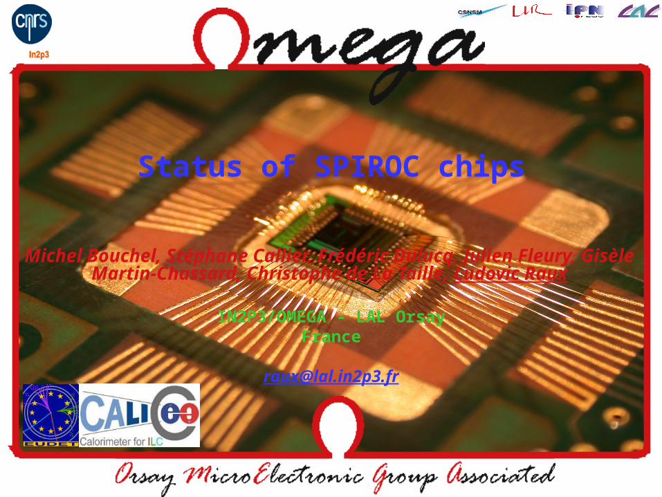
Reminder : SPIROC main features• 36-Channel ASIC• Internal input 8-bit DAC (0-5V) for individual SiPM gain
adjustment• Energy measurement : 14 bits
– 2 gains (1-10) + 12 bit ADC 1 pe 2000 pe– Variable shaping time from 25ns to 175ns – pe/noise ratio : 11
• Auto-trigger on MIP or spe– pe/noise ratio on trigger channel : 24– Fast shaper : ~10ns– Auto-Trigger on 1/3 pe (50fC)
• Time measurement : – 12-bit Bunch Crossing ID (coarse time measurement)– 12-bit TDC step~100 ps (fine time measurement)
• Analog memory for time and charge measurement: depth = 16• Low consumption : ~25µW per channel (in power pulsing mode)• Individually addressable calibration injection capacitance• Embedded features (bandgap, 10-bit DAC, etc.)• Multiplexed analog output for physics prototype DAQ• 4k internal memory and daisy chain readout
Fabricated in SiGe AMS 0.35 µmSubmitted in June 2007
Delivered in October 2007Chip area: 30 mm² (4.2mm ×
7.2mm)
jeudi 19 février 2009 Status of Spiroc - Ludovic Raux - Calice meeting, Daegu, South Korea 3
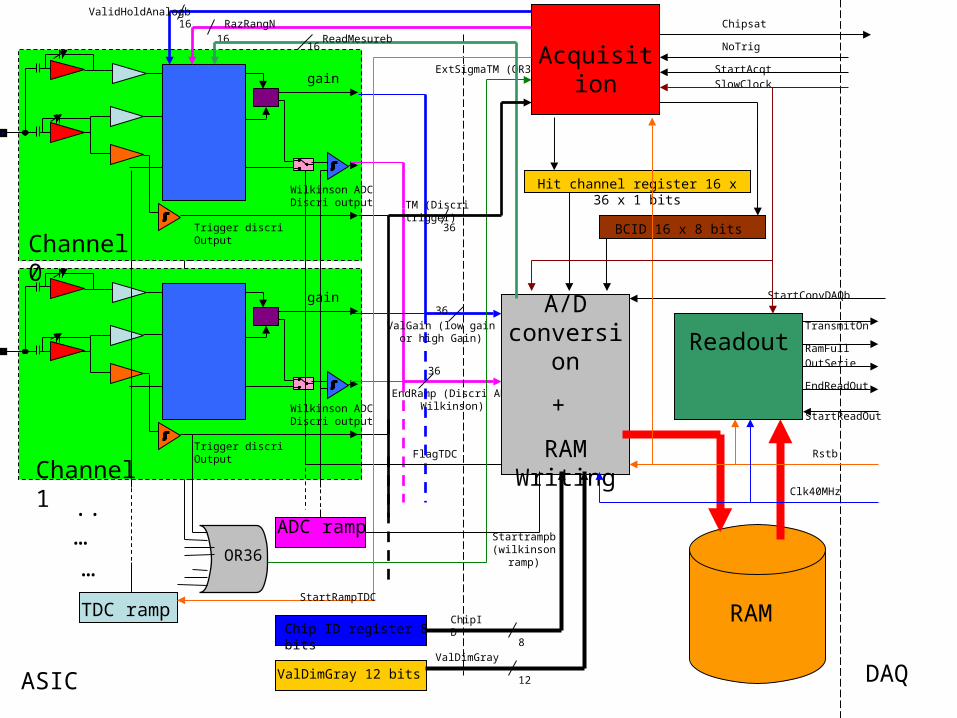
SPIROC general block scheme
DAQASIC
Chip ID register 8 bits
gain
Trigger discri Output
Wilkinson ADC Discri output
gain
Trigger discri Output
Wilkinson ADC Discri output
..…
OR36
EndRamp (Discri ADC Wilkinson)
36
36
36
TM (Discri trigger)
ValGain (low gain or high Gain)
ExtSigmaTM (OR36)
Channel 1
Channel 0
ValDimGray 12 bits
…
Acquisition
Readout
A/D conversion
+
RAM Writing
RAM
FlagTDC
ValDimGray
12
8
ChipID
Hit channel register 16 x 36 x 1 bits
TDC rampStartRampTDC
BCID 16 x 8 bits
ADC rampStartrampb (wilkinson
ramp)
16
16ValidHoldAnalogb
RazRangN
16ReadMesureb
Rstb
Clk40MHz
SlowClock
StartAcqt
StartConvDAQb
StartReadOut
NoTrig
RamFull
TransmitOn
OutSerie
EndReadOut
Chipsat
jeudi 19 février 2009 Status of Spiroc - Ludovic Raux - Calice meeting, Daegu, South Korea 4
©B. Lutz (DESY)
SNR=3.8
©B. Lutz (DESY)
SNR=3.8
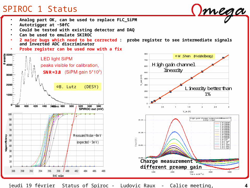
SPIROC 1 Status• Analog part OK, can be used to replace FLC_SiPM• Autotrigger at ~50fC• Could be tested with existing detector and DAQ• Can be used to emulate SKIROC• 2 major bugs which need to be corrected : probe register to see intermediate signals and
inverted ADC discriminator• Probe register can be used now with a fix
Charge measurement at different preamp gain
0.15
0.10
0.05
0.00
Vo
ut (V
)
500400300200100
Time (x10-9
s)
Cf=100fF Cf=100fF Cf=200fF Cf=300fF Cf=400fF Cf=500fF Cf=600fF Cf=700fF Cf=800fF Cf=900fF Cf=1pF Cf=1.1pF Cf=1.2F Cf=1.3pF Cf=1.4pF Cf=1.5pF
High gain charge output at different Cf Qinj= 1.5pC
S-curves
0
10
20
30
40
50
60
70
80
90
100
388 390 392 394 396 398 400 402 404 406 408
DAC value
trigg
er e
ffici
ency Measured Noise ~8mV
(expected ~ 5mV)
©B. Lutz (DESY)
High gain channellinearity
Linearity better than1%
©W.Shen (Heidelberg)
jeudi 19 février 2009 Status of Spiroc - Ludovic Raux - Calice meeting, Daegu, South Korea 5
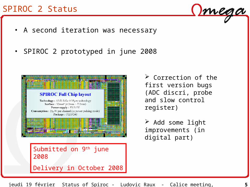
SPIROC 2 Status
• A second iteration was necessary
• SPIROC 2 prototyped in june 2008
Submitted on 9th june 2008
Delivery in October 2008
Correction of the first version bugs (ADC discri, probe and slow control register)
Add some light improvements (in digital part)
jeudi 19 février 2009 Status of Spiroc - Ludovic Raux - Calice meeting, Daegu, South Korea 6
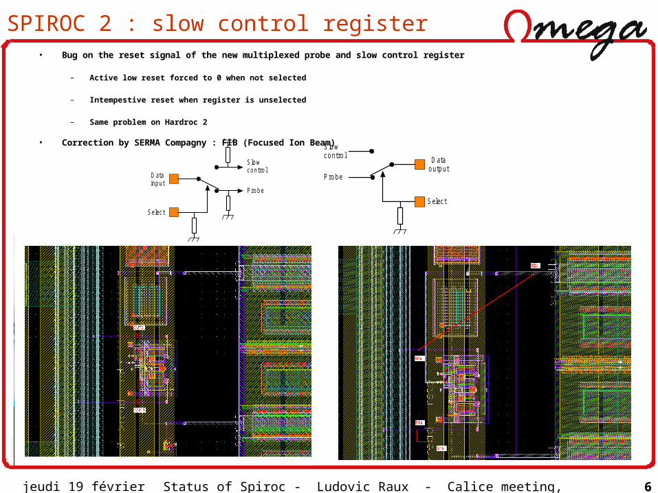
SPIROC 2 : slow control register• Bug on the reset signal of the new multiplexed probe and slow control register
– Active low reset forced to 0 when not selected
– Intempestive reset when register is unselected
– Same problem on Hardroc 2
• Correction by SERMA Compagny : FIB (Focused Ion Beam)
S elec t
D atao utp ut
S lo wc o ntro l
P ro b e
S lo wc o ntro l
P ro b e
S elec t
D atainp ut
jeudi 19 février 2009 Status of Spiroc - Ludovic Raux - Calice meeting, Daegu, South Korea 7
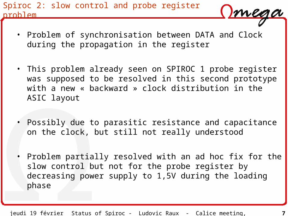
Spiroc 2: slow control and probe register problem
• Problem of synchronisation between DATA and Clock during the propagation in the register
• This problem already seen on SPIROC 1 probe register was supposed to be resolved in this second prototype with a new « backward » clock distribution in the ASIC layout
• Possibly due to parasitic resistance and capacitance on the clock, but still not really understood
• Problem partially resolved with an ad hoc fix for the slow control but not for the probe register by decreasing power supply to 1,5V during the loading phase
jeudi 19 février 2009 Status of Spiroc - Ludovic Raux - Calice meeting, Daegu, South Korea 8
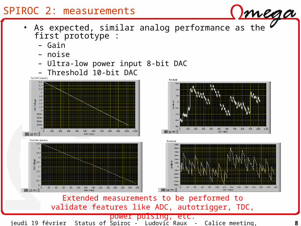
SPIROC 2: measurements
• As expected, similar analog performance as the first prototype :– Gain– noise– Ultra-low power input 8-bit DAC– Threshold 10-bit DAC
Extended measurements to be performed to validate features like ADC, autotrigger, TDC, power pulsing, etc.
jeudi 19 février 2009 Status of Spiroc - Ludovic Raux - Calice meeting, Daegu, South Korea 9
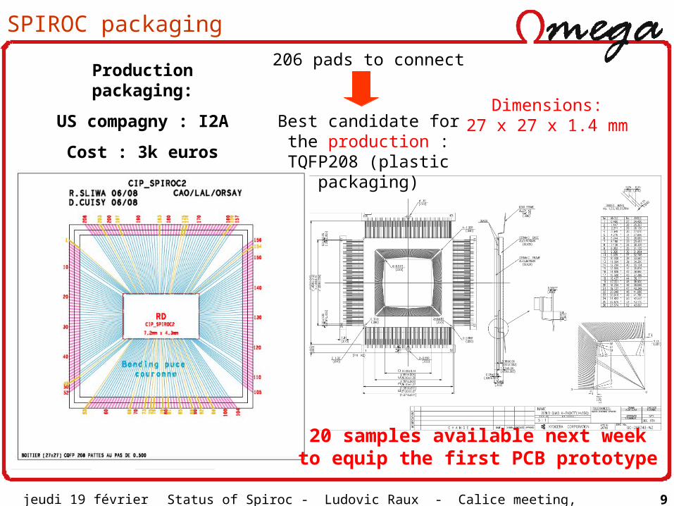
SPIROC packaging
206 pads to connect
Best candidate for the production : TQFP208
(plastic packaging)
Dimensions:27 x 27 x 1.4 mm
Production packaging:
US compagny : I2A
Cost : 3k euros
20 samples available next week to equip the first PCB prototype
jeudi 19 février 2009 Status of Spiroc - Ludovic Raux - Calice meeting, Daegu, South Korea 10
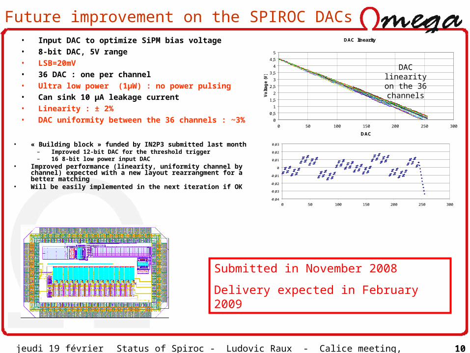
Future improvement on the SPIROC DACs
• « Building block » funded by IN2P3 submitted last month– Improved 12-bit DAC for the threshold trigger– 16 8-bit low power input DAC
• Improved performance (linearity, uniformity channel by channel) expected with a new layout rearrangment for a better matching
• Will be easily implemented in the next iteration if OK
Submitted in November 2008
Delivery expected in February 2009
DAC linearity
0
0,5
1
1,5
2
2,5
3
3,5
4
4,5
5
0 50 100 150 200 250 300
DAC
Vo
lta
ge
(V
)
-0,04
-0,03
-0,02
-0,01
0
0,01
0,02
0,03
0 50 100 150 200 250 300
DAC linearity on the 36 channels
• Input DAC to optimize SiPM bias voltage• 8-bit DAC, 5V range• LSB=20mV• 36 DAC : one per channel• Ultra low power (1µW) : no power pulsing• Can sink 10 µA leakage current• Linearity : ± 2%• DAC uniformity between the 36 channels :
~3%
jeudi 19 février 2009 Status of Spiroc - Ludovic Raux - Calice meeting, Daegu, South Korea 11
Conclusion
• SPIROC 2 chip – Very conservative prototype compared to the first one with corrections of
the first version bugs (ADC discri, probe and slow control register) and adding some light improvements (in digital part)
– New bug on the slow control and probe register has appeared. The bug on the slow control can be circumvented to operate the chip but not on the probe register
– The first measurement results give similar results as the first prototype, but it is now essential to perform extended measurements to see if the chip can be used for the EUDET prototype (ADC performance, auto-trigger, power pulsing,etc.)
– Chip in final package: TQFP 208 : 20 Samples available next week for the first PCB prototype
– Next chip will go with the hardroc engineering run (Summer 2009?)
jeudi 19 février 2009 Status of Spiroc - Ludovic Raux - Calice meeting, Daegu, South Korea 12
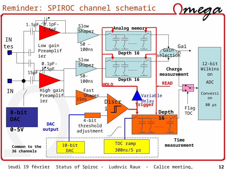
Reminder: SPIROC channel schematic
IN test 50 -100ns
50-100ns
Gain selection
4-bit threshold adjustment
10-bit DAC
15ns
DAC output
HOLD
Slow Shaper
Slow Shaper
Fast Shaper
Time measurement
Charge measurement
TDC ramp
300ns/5 µs
12-bit Wilkinson
ADC
Trigger
Depth 16
Depth 16
Depth 16
Common to the 36 channels
8-bit DAC
0-5V
Low gain Preamplifier
High gain Preamplifier
Analog memory
15pF
1.5pF
0.1pF-1.5pF
Conversion
80 µs
READ
Variable delay
0.1pF-1.5pF
IN
Discri
Gain
Flag TDC
jeudi 19 février 2009 Status of Spiroc - Ludovic Raux - Calice meeting, Daegu, South Korea 13
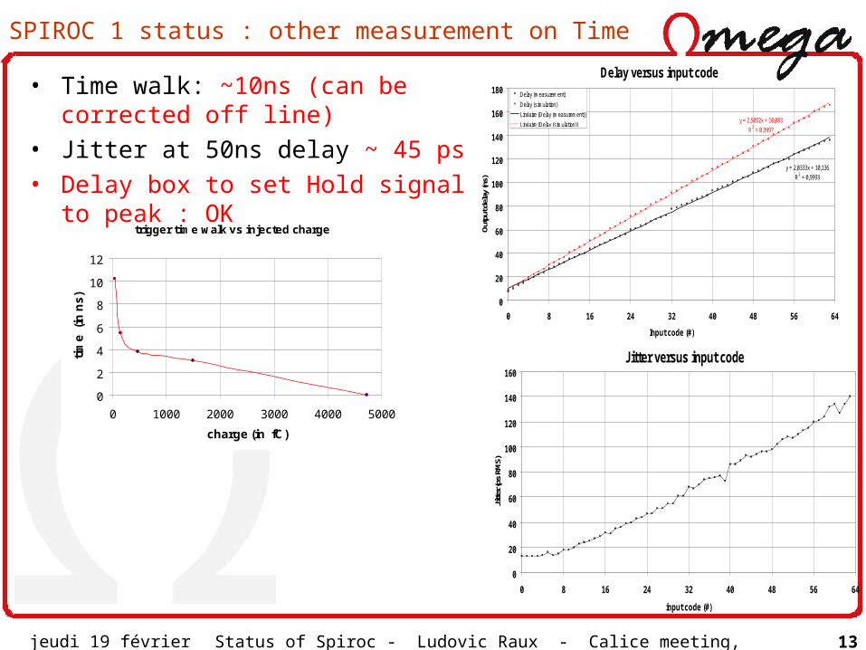
SPIROC 1 status : other measurement on Time
Jitter versus input code
0
20
40
60
80
100
120
140
160
0 8 16 24 32 40 48 56 64
input code (#)
Jitte
r (ps
RM
S)
Delay versus input code
y = 2,0333x + 10,136
R2 = 0,9993
y = 2,5032x + 10,083
R2 = 0,9997
0
20
40
60
80
100
120
140
160
180
0 8 16 24 32 40 48 56 64
Input code (#)
Outp
ut d
elay
(ns)
Delay (measurement)
Delay (simulation)
Linéaire (Delay (measurement))
Linéaire (Delay (simulation))
trigger time walk vs injected charge
0
2
4
6
8
10
12
0 1000 2000 3000 4000 5000
charge (in fC)
tim
e (
in n
s)
• Time walk: ~10ns (can be corrected off line)
• Jitter at 50ns delay ~ 45 ps• Delay box to set Hold signal to
peak : OK
Recommended


![W. Shen arXiv:0911.1566v1 [physics.ins-det] 8 Nov …azusa.shinshu-u.ac.jp/~coterra/EBUreferences/Spiroc/0911...y/Pulsar, MEPh tical iden to the devices used in AHCAL test b eam op](https://img.pdfslide.net/doc/110x75/5f1a0d93407f6d435848a9ac/w-shen-arxiv09111566v1-8-nov-azusashinshu-uacjpcoterraebureferencesspiroc0911.jpg)