Embed Size (px)
Citation preview

1
Welcome
to
My Presentation
Presentation on
2
An Overview of 16MW
PRAN
Power Stations
Prepared
by
Md.Salim Bhuiyan
ID#11105037
Prog#BSEEE
27 December 2014
3
IUBAT-International University of Business Agriculture and Technology
Contents
4
Introduction
Objective
Company overview
Power generation system
Operation and Distribution
Recommendations
Conclusion
Introduction
5
Electricity generation is the process of generating electrical
power from other sources of primary energy
Electric Energy is the most popular form of energy
Due to failure of national grid, private industry and owners are
using their own power plants & generators combining with
national grid to meet the demand of electricity
Objective
6
Broad objective:
The prime objectives of this practicum project are to extrovert my theoretical
knowledge to the practical field and understanding the performance of the
parameters in case of Power Generation, Operation, Distribution etc
Specific Objective:
To study on Power Generation Process
To study on Controlling Apparatus and maintenance
To coordinate the theories of power generation in a real life Situation
To perform in line with organizational needs & goals
Company overview
7
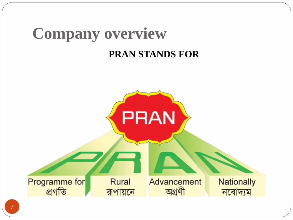
PRAN STANDS FOR
Organization Overview
8
PRAN started its operation in 1981 in Bangladesh
Bangladesh’s largest grower and processor of fruits and vegetables
PRAN Export 94 Countries of the world recently
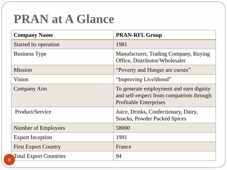
PRAN at A GlanceCompany Name PRAN-RFL Group
Started its operation 1981
Business Type Manufacturer, Trading Company, Buying
Office, Distributor/Wholesaler
Mission “Poverty and Hunger are curses”
Vision “Improving Livelihood”
Company Aim To generate employment and earn dignity
and self-respect from compatriots through
Profitable Enterprises
Product/Service Juice, Drinks, Confectionary, Dairy,
Snacks, Powder Packed Spices
Number of Employees 58000
Export Inception 1991
First Export Country France
Total Export Countries 949
Power Generation System
10
PRAN Power Station
11
Main apparatus :
1. Generator
2. Alternator
3. Power panel
4. Bus bar
5. Power factor improvement plant (PFI)
6. Chiller
7. Different types of circuit breaker
8. Conventional copper wire
9. Current transformers
10. Potential transformers
11. Measuring instruments and so on
Introduction to a Gas Generator
12
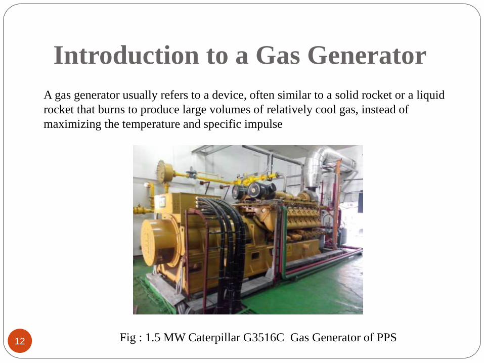
A gas generator usually refers to a device, often similar to a solid rocket or a liquid
rocket that burns to produce large volumes of relatively cool gas, instead of
maximizing the temperature and specific impulse
Fig : 1.5 MW Caterpillar G3516C Gas Generator of PPS
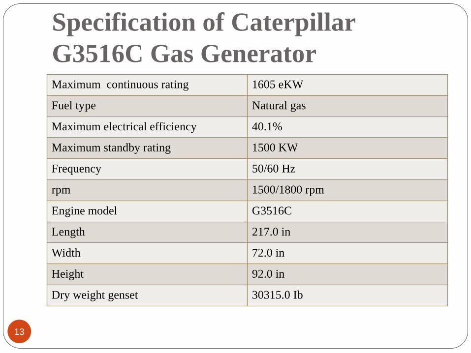
Specification of Caterpillar
G3516C Gas Generator
13
Maximum continuous rating 1605 eKW
Fuel type Natural gas
Maximum electrical efficiency 40.1%
Maximum standby rating 1500 KW
Frequency 50/60 Hz
rpm 1500/1800 rpm
Engine model G3516C
Length 217.0 in
Width 72.0 in
Height 92.0 in
Dry weight genset 30315.0 Ib
Power Generation Process
14
Though a generator is a single device that functionally converts fuel into
electricity, it is, in essence, two separate components that work together in
order to produce power
The two components- The engine and the electromagnetic generator are
connected by a crankshaft, facilitating the easy transfer of the mechanical
energy produced by the engine to the magnets of the generator assembly
A diesel engine burns diesel fuel where a gas engine burns natural gas in order
to produce mechanical energy in form of rotation, for the generator, which
converts the mechanical energy into electricity by using electromagnet
Working Procedure of a
Generator
15
A generator consists of a rotating magnetic field called a Rotor and a stationary
coil of wire called a Stator
Natural gas generators, use natural gas (methane) that utilities supply through
underground lines to generate electricity
An internal combustion engine injects a mixture of fuel and air into a
combustion chamber, where a piston compresses the mixture
A spark plug ignites the fuel, driving the piston down and turning a crankshaft
Cont…..
16
The crankshaft, in turn, spins the generator's rotor in an electromagnetic field
As the rotor turns, its magnetic field cuts across the stationary stator. A voltage
is induced into the stator windings. Regulated current delivered to the rotor is
called "Excitation" current
Excitation winding unregulated AC output is delivered to an electronic voltage
regulator
When an electrical load is connected across the Stator power windings, the
circuit is completed and an electrical current will flow
Cont…..
17
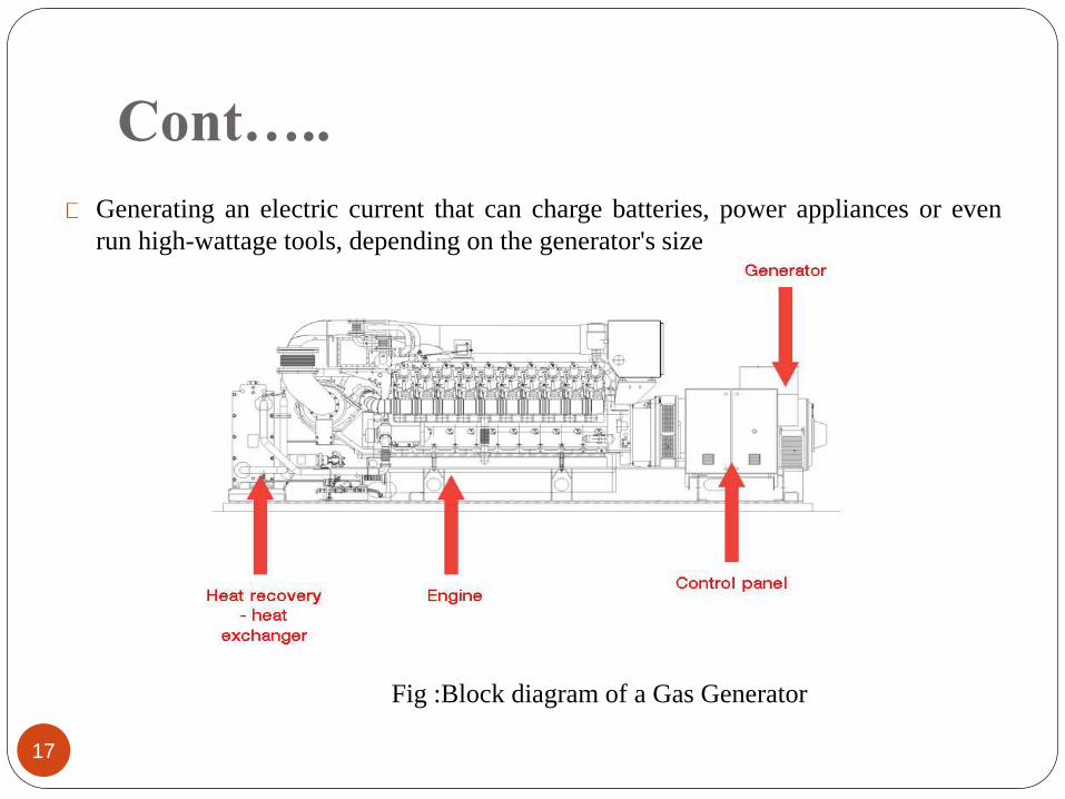
Generating an electric current that can charge batteries, power appliances or even
run high-wattage tools, depending on the generator's size
Fig :Block diagram of a Gas Generator
Speed & Frequency
18
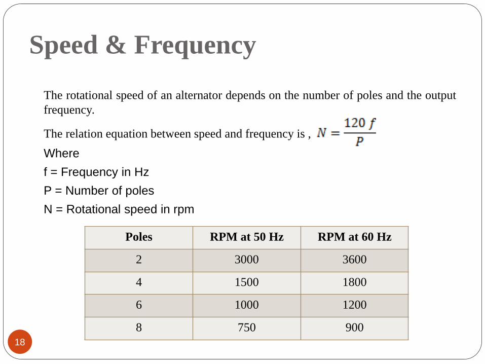
The rotational speed of an alternator depends on the number of poles and the output
frequency.
The relation equation between speed and frequency is ,
Where
f = Frequency in Hz
P = Number of poles
N = Rotational speed in rpm
Poles RPM at 50 Hz RPM at 60 Hz
2 3000 3600
4 1500 1800
6 1000 1200
8 750 900
Main components of a generator
19
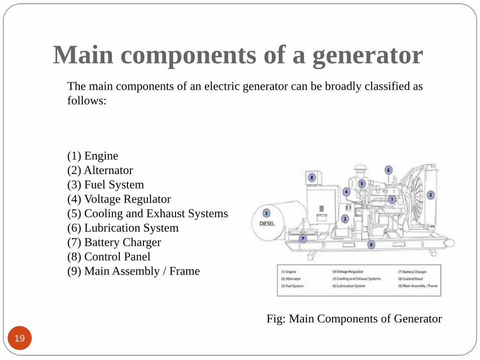
The main components of an electric generator can be broadly classified as
follows:
(1) Engine
(2) Alternator
(3) Fuel System
(4) Voltage Regulator
(5) Cooling and Exhaust Systems
(6) Lubrication System
(7) Battery Charger
(8) Control Panel
(9) Main Assembly / Frame
Fig: Main Components of Generator
Engine
20
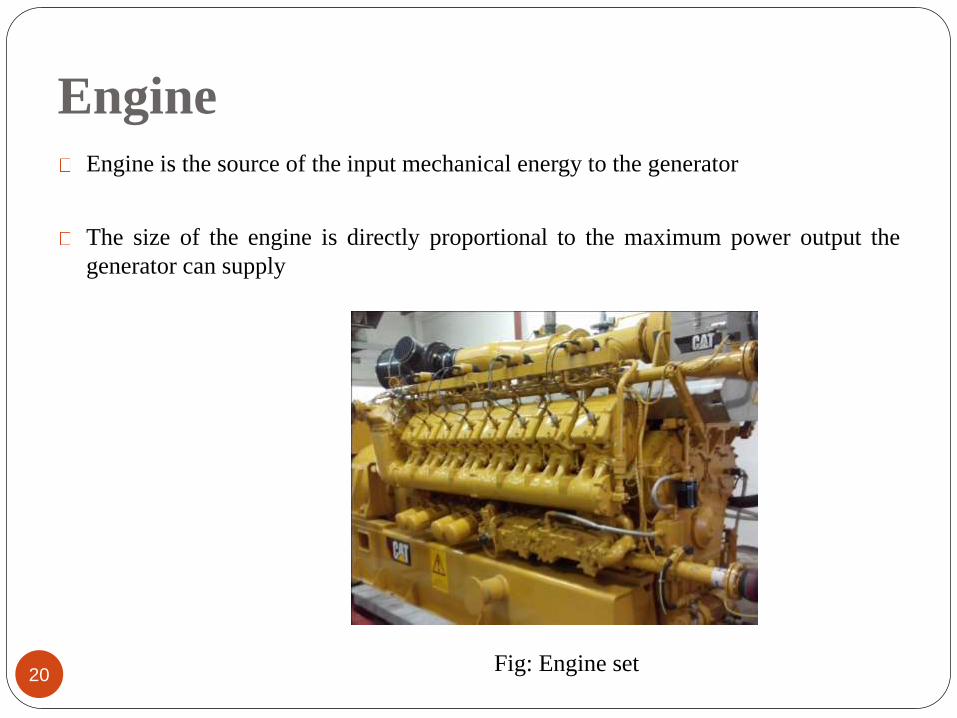
Engine is the source of the input mechanical energy to the generator
The size of the engine is directly proportional to the maximum power output the
generator can supply
Fig: Engine set
Alternator
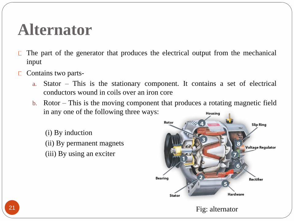
21
The part of the generator that produces the electrical output from the mechanical
input
Contains two parts-
a. Stator – This is the stationary component. It contains a set of electrical
conductors wound in coils over an iron core
b. Rotor – This is the moving component that produces a rotating magnetic field
in any one of the following three ways:
(i) By induction
(ii) By permanent magnets
(iii) By using an exciter
Fig: alternator
Fuel System
22
The fuel tank usually has sufficient capacity to keep the generator operational
for 6 to 8 hours on an average
Generator engines operate on a variety of fuels such as diesel, gasoline,
propane or natural gas
Smaller engines usually operate on gasoline while larger engines run on diesel,
liquid propane, propane gas, or natural gas
Automatic Voltage Regulator
23
A voltage regulator is an electrical regulator designed to automatically
maintain a constant voltage level
A "Reference" voltage has been preset into the Voltage Regulator
An "Actual" ("sensing") voltage is delivered to the Voltage Regulator via
sensing leads
If actual (sensing) voltage is greater than the preset voltage, the Regulator will
decrease the regulated current flow to the Rotor
If actual (sensing) voltage is less than the preset voltage, the Regulator will
increase the regulated current flow to the Rotor
Cooling & Exhaust Systems
24
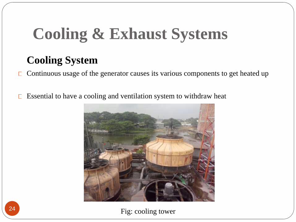
Cooling System
Continuous usage of the generator causes its various components to get heated up
Essential to have a cooling and ventilation system to withdraw heat
Fig: cooling tower
Exhaust System
25
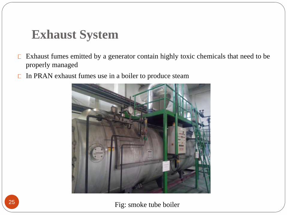
Exhaust fumes emitted by a generator contain highly toxic chemicals that need to be
properly managed
In PRAN exhaust fumes use in a boiler to produce steam
Fig: smoke tube boiler
Lubricating System
26
Moving parts of engine requires lubrication to ensure durability and smooth
operations for a long period of time
Internal combustions engines require lubrication in operation that moving parts
slide smoothly over each other
Insufficient lubrication causes uneven metal-to-metal contact, friction, heat
build-up etc
Battery Charger
27
The start function of a generator is battery-operated
Starting motor of a generator is operated by 24v D.C battery
The battery charger keeps the generator battery charged by supplying required
voltage
All generators have customized housings that provide a structural base support
frame also allows for the generator to be earthed for safety
Main Assembly / Frame
28
Operation and Distribution
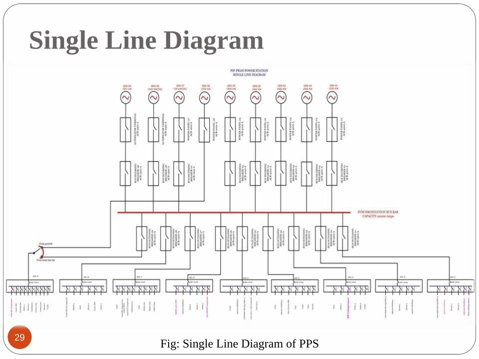
Single Line Diagram
29Fig: Single Line Diagram of PPS
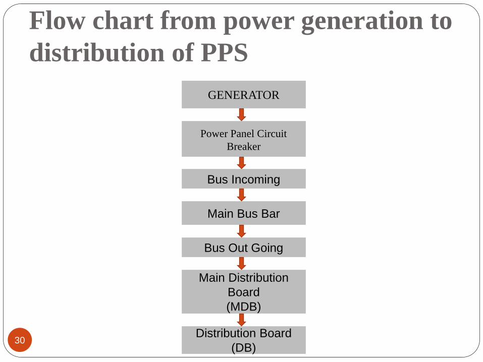
Flow chart from power generation to
distribution of PPS
30
GENERATOR
Power Panel Circuit
Breaker
Bus Incoming
Main Bus Bar
Bus Out Going
Main Distribution
Board
(MDB)
Distribution Board
(DB)
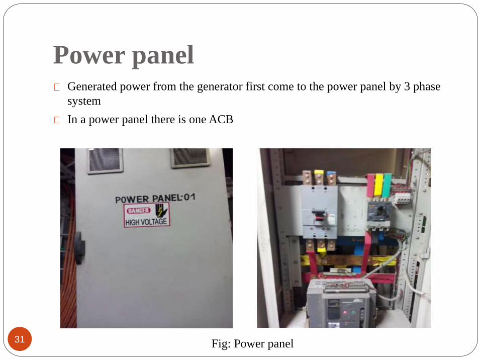
Power panel
31
Generated power from the generator first come to the power panel by 3 phase
system
In a power panel there is one ACB
Fig: Power panel
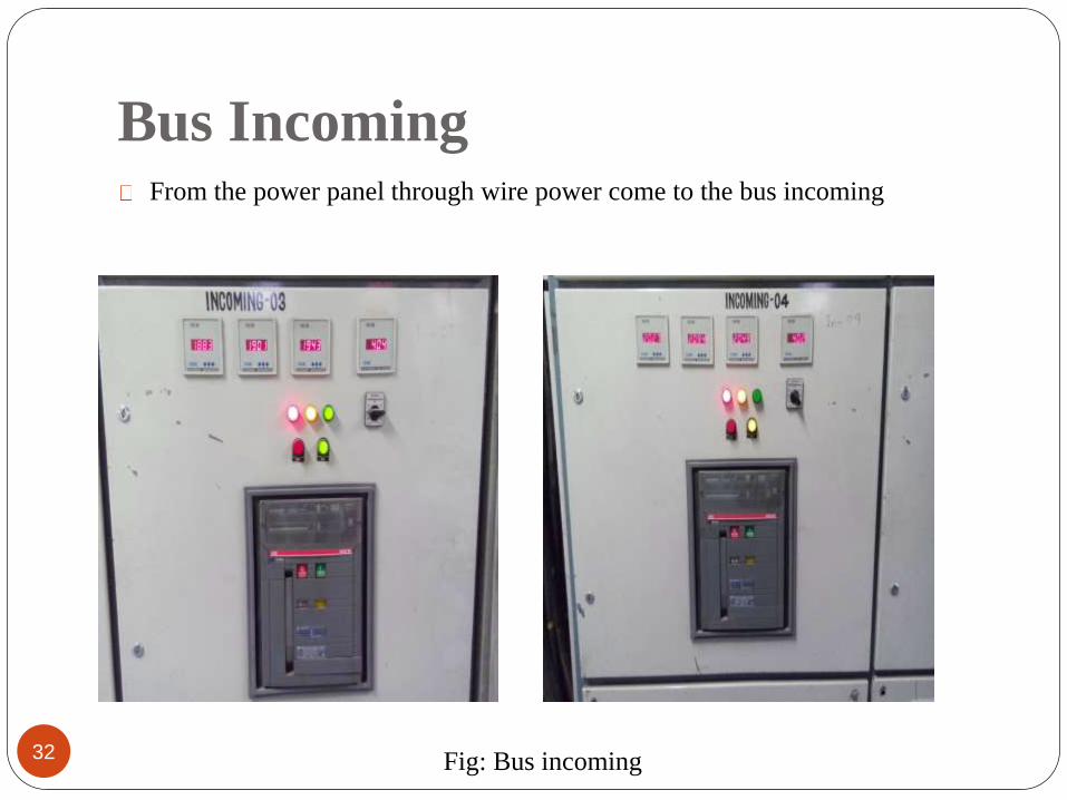
Bus Incoming
32
From the power panel through wire power come to the bus incoming
Fig: Bus incoming
Main bus bar
33
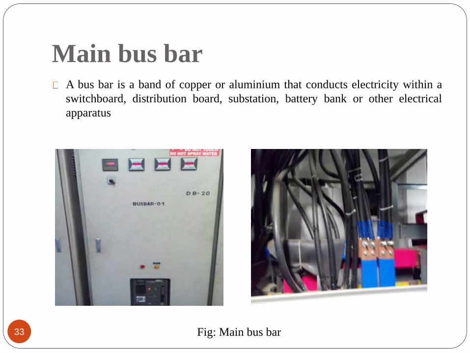
A bus bar is a band of copper or aluminium that conducts electricity within a
switchboard, distribution board, substation, battery bank or other electrical
apparatus
Fig: Main bus bar
Bus Out going
34
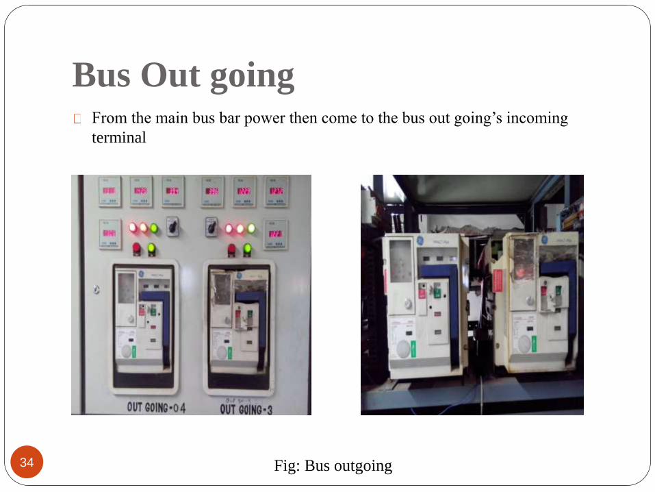
From the main bus bar power then come to the bus out going’s incoming
terminal
Fig: Bus outgoing
Main Distribution board
35
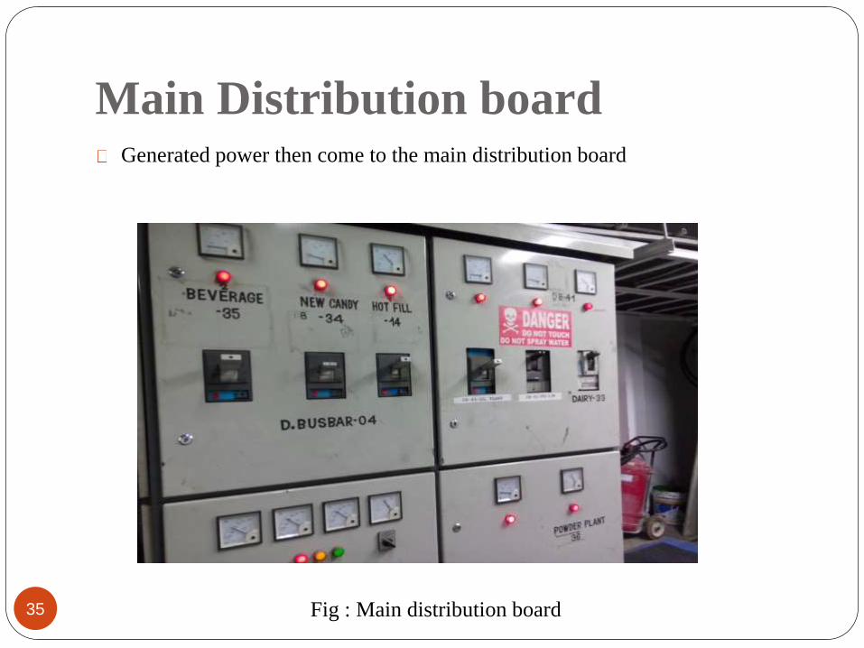
Generated power then come to the main distribution board
Fig : Main distribution board
Distribution Board
36
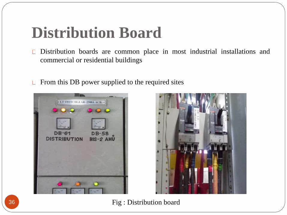
Distribution boards are common place in most industrial installations and
commercial or residential buildings
From this DB power supplied to the required sites
Fig : Distribution board
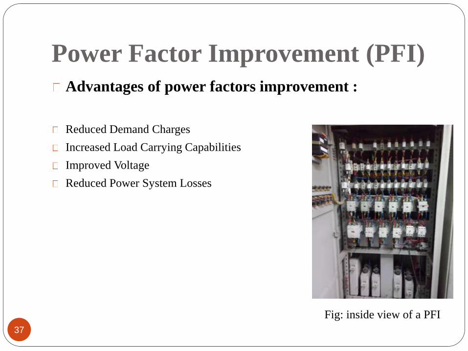
Power Factor Improvement (PFI)
37
Advantages of power factors improvement :
Reduced Demand Charges
Increased Load Carrying Capabilities
Improved Voltage
Reduced Power System Losses
Fig: inside view of a PFI
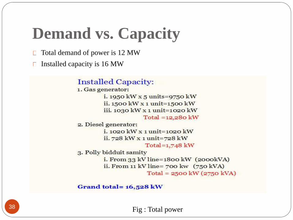
Demand vs. Capacity
38
Total demand of power is 12 MW
Installed capacity is 16 MW
Fig : Total power
Cost Analysis
39
Using Gas
Required gas for producing 1 KWh electricity = 0.30 m3
1 m3 gas = 4.20 tk.
1 KWh = (4.20 x 0.30= 1.26 tk.)
Using Diesel
1 KWh electricity cost = 18 tk.
From REB
1 KWh electricity cost = 6.30 tk.
Recommendations
40
Need to think about other renewable energy source
For better efficiency they should use close type cooling tower instead of open
type
Instead of using conventional copper wire they need to think about using
BBT(bus bar trunking system)
Cont…..
41
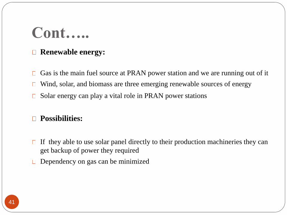
Renewable energy:
Gas is the main fuel source at PRAN power station and we are running out of it
Wind, solar, and biomass are three emerging renewable sources of energy
Solar energy can play a vital role in PRAN power stations
Possibilities:
If they able to use solar panel directly to their production machineries they can
get backup of power they required
Dependency on gas can be minimized
42
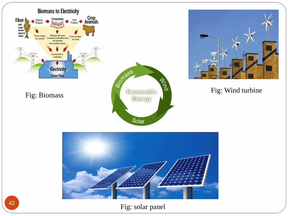
Fig: BiomassFig: Wind turbine
Fig: solar panel
Cont…..
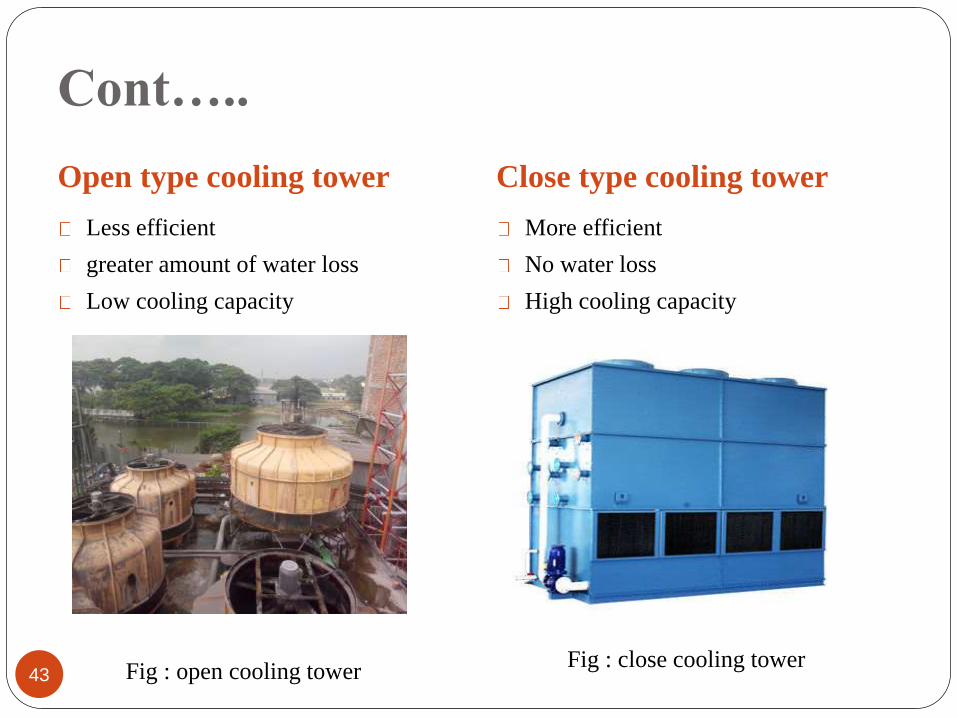
Open type cooling tower Close type cooling tower
43
Less efficient
greater amount of water loss
Low cooling capacity
More efficient
No water loss
High cooling capacity
Fig : open cooling towerFig : close cooling tower
Cont…..
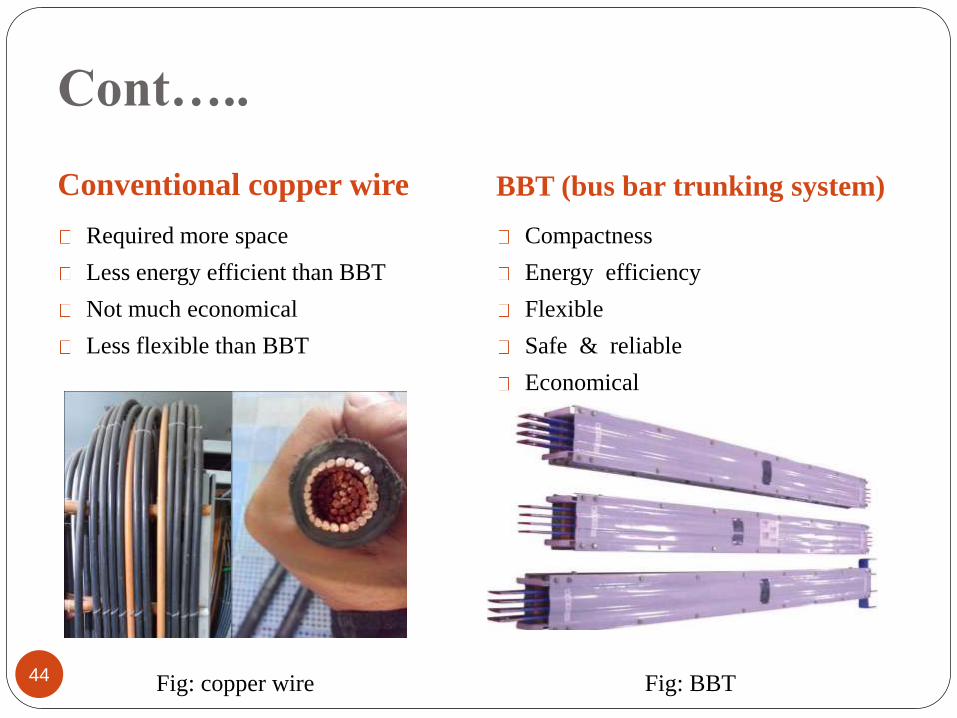
Conventional copper wire BBT (bus bar trunking system)
44
Required more space
Less energy efficient than BBT
Not much economical
Less flexible than BBT
Compactness
Energy efficiency
Flexible
Safe & reliable
Economical
Fig: copper wire Fig: BBT
Conclusion
45
In electricity crisis of Bangladesh the own power generation is a matter of
happiness which is done by PRAN-RFL Group. The main reason for the power
crisis is the shortage of supply. Demand is never meet by supply. Generation of
power needs to be increased transferred to the desired distribution centers of
power.
It had been a great experience for me. I am very glad that I did my internship in
such a field where I learned many things about power generation and
controlling system, which will be very helpful in my professional life.

46

47