Embed Size (px)
Citation preview
CCNA FILE
SUBMITTED BY
SHEFALI GARG
BHARTI GARG
(BTECH CSE , PUNJABI UNIVERSITY PATIALA)

INDEX
1) NETWORK INTRODUCTION
2) WIRED/WIRELESS MEDIA
3) APPLICATIONS OF NETWORK
4) IP VERIFICATION OF SYSTEM
5) DEBUGGING TOOLS
6) TYPES OF NETWORKS
7) NETWORK CABLING
8) IP ADDRESSING
9) NETWORK MODELS OSI/ TCP/IP
10) IP SUBNETTING
11) CONFIGURING IOS DEVICES
12) BASIC ROUTER CONFIGURATIONS
13) RIP
14) EIGRP
15) DEFAULT ROUTI NG
16) OSPF
17) BGP
18) LAN SWITCHING
19) VLANS
20) INTERVLAN ROUTING
21) VTP
22) ACL
23) NAT
24) CISCO HIERARCHICAL MODEL

NETWORK :
It is connection of two or more devices (PCs, servers, smartphones etc) through a media for the purpose of –
1.Sharing information 2.Resource utilisation 3.Remote connection
Media used in network could be wired or wireless.
WIRED MEDIA includes twisted pairs ( LAN), coaxial (WAN)
and fibre optics.
Various standards used is token ring, Ethernet, FDDI.
TOKEN RING

FIBRE DISTRIBUTED DATA INTERFACE
WIRELESS MEDIA
Transmission of waves take place in EM spectra. These include
1.Radiowaves 2. Microwaves 3.Infrared
INFRARED
Unidirectional in nature.
FREQUENCY: 300 GHz to 400 THz .
RANGE: Below 10 metre.
It is used in PAN (Personal area network) which includes:
IrDA (Infrared Data Association) : Line-Of-Sight implemented
on portable devices i.e remote controllers, mobiles, laptops ,
cameras etc.
Bluetooth :
Range : 60 metre
It is used for transmitting higher no. of bytes than IrDA.

MICROWAVES:
Unidirectional
FREQUENCY : 1-300 GHz
Application : X.25 , T-lines .
RADIOWAVES
Omnidirectional
FREQUENCY: 3 KHz to 1 GHz
Application : Muticasting , AM and FM radios ,Televisions etc.
Wi-Fi
It stands for Wireless fidelity. Then IEEE standard is 802.11. It
uses radiowaves to provide connectivity within the LAN.
RANGE: < 100 m
CURRENT VERSION: 802.11ac , provides range of 90 m.
Many devices can use Wi-Fi, e.g., personal computers, video-
game consoles, smartphones, some digital cameras and digital
audio players. These can connect to a network resource such as
the Internet via a wireless network access point. Such an access
point (or hotspot) has a range of about 20 meters (66 feet)
indoors and a greater range outdoors.

APPLICATIONS OF NETWORKING
1. REMOTE CONNECTION: It is a connection between a
machine and the administrator at some remote location.
Teamviewer is the software used to provide remote
connection on Internet.
Remote connection in a network :
Requirement: a) Software Remote Desktop connection
b) IP address and the Credentials of the host you
want to get the remote of.
Steps: 1. My Computer(right click) Properties remote
settings Allow Remote Assistance.
2. Go to start and open remote desktop connection.
3. Fill the IP address and the Credentials and connect.
One device can have remote of various devices but a single
device can provide the remote session to single device only.
2. RESOURCE SHARING: A shared resource is a computer resource made available from
one host to other on a computer network.
With resource sharing, the limited resources can be shared by
multiple devices connected over a network. For example, with
sharing single printer can serve emerging demands from
various devices one at a time.
Steps:
To share the Local printer –
a) Go to start and select devices and printers.
b) Select a particular printer you want to share, right
click, printer properties sharing
specify the share name to the printer ok.
To get access of the shared remote printer—
a) Go to start and select device and printers .
b) Select ‘add a printer’ Add a network, wireless or
bluetooth printer select the shared printer.

IP VERIFICATION OF SYSTEM
HOW to Verify IP address of the system connected to
network???
a) IPCONFIG is the command used to verify the IP address of
the system.
b) Static verification
Open control panel network sharing centre Adapter
settings select network connection(right click) status
Details.
DEBUGGING TOOLS
There are several tools that can be used in the Internet. a) PING (packet internet groper):

This command is a very common method for troubleshooting the accessibility of devices. It uses a series of Internet Control Message Protocol (ICMP) Echo messages to determine:
a) Whether a remote host is active or inactive
b) The round-trip delay in communicating with the host. c) Packet loss.
The ping command first sends an echo request packet to an address, then waits for a reply. The ping is successful only if:
a) The echo request gets to the destination, and b) The destination is able to get an echo reply back to the source within a predetermined time called a timeout. The default value of this timeout is two seconds on Cisco routers.
Ping is also used to find the IP address of the host when name is known.
b) TRACEROUTE :
It is a computer network diagnostic tool for displaying the route (path) and measuring transit delays of packets across an Internet Protocol (IP) network. The history of the route is

recorded as the round-trip times of the packets received from each successive host (remote node) in the route path); the sum of the mean times in each hop indicates the total time spent to establish the connection. Traceroute proceeds unless all (three) sent packets are lost more than twice, then the connection is lost and the route cannot be evaluated. Ping, on the other hand, only computes the final round-trip times from the destination point.
TYPES OF NETWORKS
A) a) intra-network b) inter-network c) Internet
a) intra network (intranet): It is the network between same
network address. Example network id 192.168.2.0 /24 implies that all devices in the intranet must have IP as 192.168.2.X (x: 1-254). Switches are commonly used in intranet.

b) inter network(internet) : It is the network connection
between two or more networks. Routers are used to connect two or more different networks via gateways.
GATEWAY: A node on a network that serves as an entrance to anothernetwork.
c)Internet : It is the global network that uses the concept of
domain name to provide different kind of services. It is the WORLD’s BIGGEST WAN. It is an international network of networks that consists of millions of private, public, academic, business, and government packet switched networks, linked by a broad array of electronic, wireless, and optical networking technologies.
Internet has the evolutionary roots in ARPANET which was
one of the world’s first operational packet switching networks
that implemented TCP/IP for the first time. The packet
switching of the ARPANET, together with TCP/IP, would form
the backbone of how the Internet works.

B) TYPES OF NETWORKs ON BASIS OF DISTANCE :
a) PAN /SAN / LAN :
Digital signals are used.
PAN range< 10 m
A personal area network (PAN) is the interconnection of
information technology devices within the range of an
individual person, typically within a range of 10 meters. For
example, a person traveling with a laptop, a personal digital
assistant (PDA), and a portable printer could interconnect them
without having to plug anything in, using some form
of wireless technology. Typically, this kind of personal area
network could also be interconnected without wires to the
Internet or other networks.
SAN range< 100m
A storage area network (SAN) is any high-performance network
whose primary purpose is to enable storage devices to
communicate with computer systems and with each other.
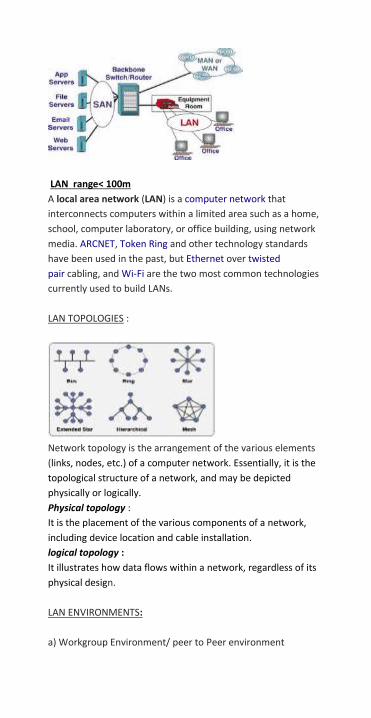
LAN range< 100m
A local area network (LAN) is a computer network that
interconnects computers within a limited area such as a home,
school, computer laboratory, or office building, using network
media. ARCNET, Token Ring and other technology standards
have been used in the past, but Ethernet over twisted
pair cabling, and Wi-Fi are the two most common technologies
currently used to build LANs.
LAN TOPOLOGIES :
Network topology is the arrangement of the various elements
(links, nodes, etc.) of a computer network. Essentially, it is the
topological structure of a network, and may be depicted
physically or logically.
Physical topology :
It is the placement of the various components of a network,
including device location and cable installation.
logical topology :
It illustrates how data flows within a network, regardless of its
physical design.
LAN ENVIRONMENTS:
a) Workgroup Environment/ peer to Peer environment

b) Domain Environment / Client-Server Environment
b) MAN / WAN :
Analog signals are used which aids long distance
transmission.
Range <= 1000 km
Protocols used are Routed and Routing protocols.

NETWORK-CABLING
Twisted pair types and categories:

Connector used in twisted Pair.
RJ-45
UTP cable often is installed using a Registered Jack 45 (RJ-45)
connector. The RJ-45 is an eight-wire connector used
commonly to connect computers onto a local-area network
(LAN), especially Ethernets.
COLOR CODING :
Two types of color coding— T568A and T568B
STRAIGHT THROUGH CABLE:
A straight-through cable has connectors on each end that are
terminated the same in accordance with either the T568A or
T568B standards. Use straight-through cables for the following
connections:
Switch to a router Ethernet port
Computer to switch
Computer to hub

CROSS OVER CABLE
For two devices to communicate through a cable that is directly
connected between the two, the transmit terminal of one device
needs to be connected to the receive terminal of the other
device. The crossover cables directly connect the following
devices on a LAN: Switch to switch Switch to hub Hub to hub Router to router Ethernet port connection Computer to computer Computer to a router Ethernet port ROLLOVER CABLE
Rollover cables, like other cabling types, got their name from
how they are wired. Rollover cables essentially have one end of
the cable wired exactly opposite from the other.
USE:
CONSOLING into cisco Routers. So also called cisco
console cable.
HOW TO PREPARE CABLE CONNECTION??
Requirement:
-CAT 5e cable
-RJ-45 connector

-scissors
-crimping tool
-cable stripper
Steps:

IP ADDRESSING
An Internet Protocol address is a numerical label assigned to
each device participating in a computer network that uses the
Internet Protocol for communication. It is 32 bit address which is represents in dotted decimal format
containing four octets.
Number of networks and number of hosts per class can be derived by this formula:
CLASSES OF IP ADDRESS:
Key points:
Subnet mask is a 32-bit number that masks an IP address,
and divides the IP address into network address and host
address. Subnet Mask is made by setting network bits to all
"1"s and setting host bits to all "0"s.
It defines the class of a network.
NETWORK BIT : These are the bits in the subnet mask that
represent the unchanged value of IP address in a network.

HOST BIT : It is the bit that is used zero or minimum in mask
that represents host a unique identity.
VALID AND INVALID ADDRESSES
Valid addresses are those which can be assigned to the host.
Invalid addresses can’t be assigned to host.
Invalid address list:
a) Network address /First address
b) Broadcast address/ Last address
c) 127.x.x.x which is used for loopback
d) 224-255.x.x.x reserved for multicasting and governmental
use.
PUBLIC AND PRIVATE ADDRESSES
PRIVATE addresses are the addresses which are available free
of cost. These are implemented to create a network.
These addresses cannot be used in a WAN or Internet
connection.
The private address blocks are:
10.0.0.0 to 10.255.255.255 (10.0.0.0 /8) 172.16.0.0 to 172.31.255.255 (172.16.0.0 /12) 192.168.0.0 to 192.168.255.255 (192.168.0.0 /16)

PUBLIC addresses are the paid and certified addresses provided by ISPs . These addresses are required for the connectivity across Internet/WAN. IPchicken.com can be used to verify one’s public address assigned to them.
Socket address (IP address(32) + port number) provides unique
identity to the host connected to the network across the
Internet.
172.16.12.3:55386 is the socket address of the system.

NETWORK MODELS
Key features:
a) It is a hypothetical model, introduced in 1970’s that works
on layered approach. It has seven layers as described above. b) Why OSI failed ? – Overhead in OSI is very high (trailers and
headers added) that hinders performance. For example for a
packet of 50 kb the overhead added in OSI is 200 kb which is
just 100 KB in TCP/IP.
c) Currently used model is TCP/IP – TCP/IP v4/ v6 which consist
of four layers. Upper three layers of OSI are combined into one
in TCP/IP that reduces the overhead considerably.
NOTE: TCP/IP comes before OSI model though it surpasses the
OSI which required more Bandwidth.
IP PROTOCOL SUITE:

IP SUBNETTING : Subnetting allows for creating multiple logical networks from a
single address block. Since we use a router to connect these
networks together, each interface on a router must have a
unique network ID. Every node on that link is on the same
network.
Use : A subnet allows the flow of network traffic between
hosts to be segregated based on a network configuration. By
organizing hosts into logical groups, subnetting can improve
network security and performance. the most recognizable
aspect of subnetting is the subnet mask. Like IP addresses, a
subnet mask contains four bytes (32 bits) and is often written
using the same "dotted-decimal" notation.
We create the subnets by using one or more of the host bits as
network bits. This is done by extending the mask to borrow
some of the bits from the host portion of the address to create
additional network bits.
Formula for calculating subnets:
2^n where n = the number of bits borrowed.
Eg n=2 implies 4 subnets created.
The number of hosts:
To calculate the number of hosts per network, we use the
formula of
2^n - 2 where n = the number of bits left for hosts.
Fig 1. Two subnets.
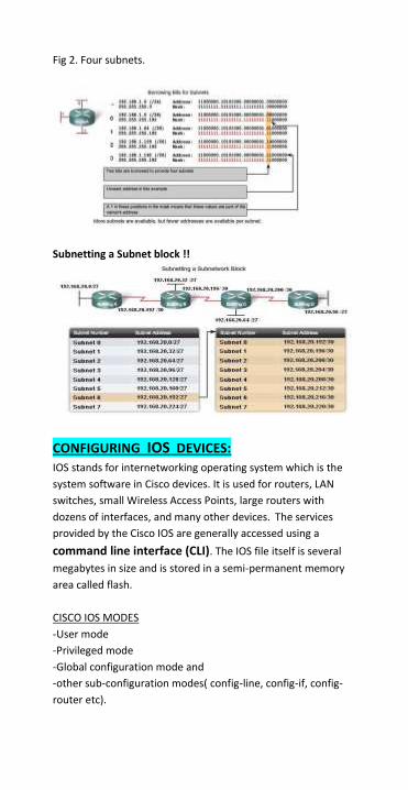
Fig 2. Four subnets.
Subnetting a Subnet block !!
CONFIGURING IOS DEVICES:
IOS stands for internetworking operating system which is the
system software in Cisco devices. It is used for routers, LAN
switches, small Wireless Access Points, large routers with
dozens of interfaces, and many other devices. The services
provided by the Cisco IOS are generally accessed using a
command line interface (CLI). The IOS file itself is several
megabytes in size and is stored in a semi-permanent memory
area called flash.
CISCO IOS MODES
-User mode
-Privileged mode
-Global configuration mode and
-other sub-configuration modes( config-line, config-if, config-
router etc).

MOVING BETWEEN DIFFERENT MODES
ACCESS METHODS:
There are several ways to access the CLI environment. The
most usual methods are:
- Console: A console uses a low speed serial connection to
directly connect a computer or terminal to the console port on the router or switch. The console port is often used to access a device when the networking services have not been started or have failed. - Telnet/vty line : A method for remotely accessing a CLI session is to telnet to the router. Unlike the console connection, Telnet sessions require active networking services on the device.

- AUX port: Another way to establish a CLI session remotely is via a telephone dialup connection using a modem connected to the router's AUX port. The AUX port can also be used locally, like the console port, with a direct connection to a computer running a terminal emulation program. Generally, the only time the AUX port is used locally instead of the console port is when there are problems using the console port. CONDITIONS FOR TELNET. Following configurations are necessary : 1) IP address to the particular interface of the device. 2) passwords to privilege mode. 3) configuring vty line mode.
How to take remote control of IOS device?? Go to the particular system command prompt ‘Telnet x.y.z.w (ip address of the remote IOS device)’.
BASIC ROUTER CONFIGURATIONS 1) Hostname:
2) line and privilege passwords:

3) IP address to the Ethernet/serial interfaces:
4) Static routes: Command : IP route x.y.z.t subnetmask p.q.r.s Where x.y.z.t is destination network address, p.q.r.s is next hop address. The networks which are not directly connected to the router are added in the routin table using this command. Eg
Verifying Your Configuration
To verify that you have properly configured static routing, enter the show ip route command and look for static routes signified by the ‘S’.
5) Dynamic Routing:
It needs to advertise only directly connected links to the router and it automatically finds the best path for routing to the destination as shown below. Static vs dynamic routing:

Categories of Dynamic Routing protocols: Interior Protocols: These help in routing within an autonomous system. These includes RIP,OSPF,EIGRP,IGRP. Exterior protocols: Routing done across autonomous systems. These include BGP and EGP.

RIP: Routing information protocol.
CHARACTERSTICS OF RIP: 1) Current version used is 2. 2) It is distance vector protocol. This protocol will find the best path taking in account number of hops only. 3) METRIC used in RIP is hop count.
4) Update msgs are sent periodically after every 30 secs via broadcast. DISADVANTAGES OF RIP:
1) This protocol has limited features. 2) Maximum hops possible is 15. After this the packet will be dropped. 3) No back ups are provided. 4) It does not support subnetting as subnet mask is not given while advertising networks.
Commands for implementing: (config)#router rip (config-router)#network n/w address
Verification:

EIGRP: Enhanced Internal Gateway Routing Protocol
Characterstics of EIGRP:
1) Hybrid Distance Vector/Link State algorithm
2) Supports VLSM (subnets/supernets).
3) It is enhanced version of IGRP. EIGRP metrics are 256
times the IGRP metric.
4) Fast convergence
5) Performs Partial Updates as needed
6) Consumes less bandwidth (no broadcasts, no periodic
updates, updates contain only changes)
Commands for implementation:
1. (config)#router eigrp AS-Number
Enable EIGRP routing and set autonomous system.
2. (config-router)# network x.x.x.x wx.wx.wx.wx Configure directly connected network. Here wx.wx.wx.wx is wild card mask which is just opposite of subnet mask.
On router 0:
On router 1:

VERIFICATION:
a) Show ip route:
b) Show IP EIGRP neighbours:
c) Show IP EIGRP topology:
DEFAULT ROUTING: Implemented on stub network (a network which has
single entry and exit point). It redirects all route paths to a single hop.

IMPLEMENTATION:
Router(config)#ip route 0.0.0.0 0.0.0.0 172.16.10.2
Send all packets destined for networks not in my routing table to 172.16.10.2
Router(config)#ip route 0.0.0.0 0.0.0.0 s0/0
Send all packets destined for networks not in my routing table out my Serial 0/0 interface
OSPF: OPEN SHORTEST PATH FIRST OSPF is a router protocol used within larger autonomous system networks in preference to the RIP. Characteristics: 1) Each router sends a link-state advertisement (LSA) whenever a change occurs in one of the routes known to the router. LSAs contain information about the route that changed only. 2) OSPF multicasts the updated information only when a change has taken place. 3) Routers exchange “Hello” messages during the convergence process to build their neighbour tables. 4) Since OSPF announces subnet masks, it supports CIDR , VLSM (Variable Length Subnetting), Supernetting (used to aggregate Class C networks) and non-contiguous network segments. 5) It supports the logical grouping of network segments into areas. Backbone area : The backbone area or area 0 or area 0.0.0.0 forms the core of an OSPF network. All other areas are connected to it, and inter-area routing happens via routers connected to the backbone area and to their own associated areas. The backbone area is responsible for distributing routing information between nonbackbone areas. Internal router (IR): An internal router has all its interfaces belonging to the same area. Area border router (ABR) : An area border router is a router that connects one or more areas to the main backbone network. It is considered a member of all areas it is connected to. An ABR keeps multiple copies of the link-state database in memory, one for each area to which that router is connected.

Backbone router (BR): A backbone router has an interface to the backbone area. Backbone routers may be also area routers, but do not have to be. Autonomous system boundary router (ASBR) : An autonomous system boundary router is a router that is connected by using more than one routing protocol and that exchanges routing information with routers autonomous systems. ASBRs typically also run an exterior routing protocol (e.g., BGP), or use static routes, or both. IMPLEMENTATION:
ON ROUTER 0 ( arearouter 100) router ospf 100 network 192.168.2.0 0.0.0.255 area 100
network 11.0.0.0 0.255.255.255 area 100
On router 1 (backbone router) router ospf 100 network 192.168.3.0 0.0.0.255 area 0 network 11.0.0.0 0.255.255.255 area 100
network 12.0.0.0 0.255.255.255 area 101
On router 2(area router 101)
router ospf 100
network 192.168.4.0 0.0.0.255 area 101
network 12.0.0.0 0.255.255.255 area 101
VERIFICATION (BR)
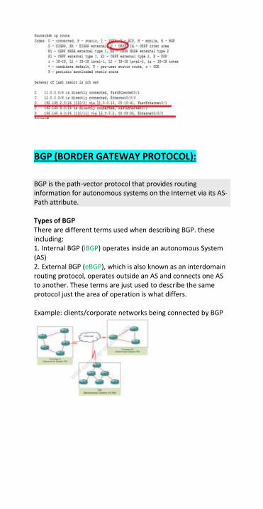
BGP (BORDER GATEWAY PROTOCOL):
BGP is the path-vector protocol that provides routing information for autonomous systems on the Internet via its AS-Path attribute. Types of BGP There are different terms used when describing BGP. these including: 1. Internal BGP (iBGP) operates inside an autonomous System (AS) 2. External BGP (eBGP), which is also known as an interdomain routing protocol, operates outside an AS and connects one AS to another. These terms are just used to describe the same protocol just the area of operation is what differs. Example: clients/corporate networks being connected by BGP

IMPLEMENTATION:
Router2 (AS 100)
router bgp 100
network 192.168.4.0
network 12.0.0.0
neighbor 14.0.0.2 remote-as 200
ROUTER6(AS 200)
router bgp 200
neighbor 14.0.0.16 remote-as 100
network 192.168.6.0
VERIFICATION( router 6):
LAN SWITCHING : LAN switching is a form of packet switching in which the data
packets are transferred from one computer to another over a
network. A bridge or a LAN switch is used that interconnects
two or more LANS and forward frames between these
networks.

SWITCH VS HUB
Initially nodes are simply connected together using hubs. As a
network grows, there are some potential problems with this
configuration.
LAYER 2 SWITCHING.
Layer 2 switching uses the MAC address from the host’s NIC’s to decide where to forward frames. Layer 2 switching is hardware based, which means switches use application-specific integrated circuit (ASICs) to build and maintain filter tables (also known as MAC address tables or CAM tables). One way to think of a layer 2 switch is as a multiport bridge. CAM TABLE: It is the table in the switch which stores MAC addresses just like routers store routing table. Initially CAM table is empty and on receiving the first packet from the connected node it broadcasts to the rest of the nodes and correspondingly update its CAM table.
LAYER 3 SWITCHING
It operates on layer 2 and layer 3. The only difference between
a layer 3 switch and router is the way the administrator creates
the physical implementation. Layer 3 switches can be placed
anywhere in the network because they handle high-
performance LAN traffic and can cost-effectively replace
routers. Layer 3 switching is all hardware-based packet
forwarding.
SWITCH = CAM + HUB
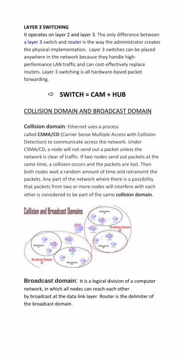
COLLISION DOMAIN AND BROADCAST DOMAIN
Collision domain: Ethernet uses a process
called CSMA/CD (Carrier Sense Multiple Access with Collision
Detection) to communicate across the network. Under
CSMA/CD, a node will not send out a packet unless the
network is clear of traffic. If two nodes send out packets at the
same time, a collision occurs and the packets are lost. Then
both nodes wait a random amount of time and retransmit the
packets. Any part of the network where there is a possibility
that packets from two or more nodes will interfere with each
other is considered to be part of the same collision domain.
Broadcast domain: It is a logical division of a computer
network, in which all nodes can reach each other
by broadcast at the data link layer. Router is the delimiter of
the broadcast domain.

REMOTE ACCESS OF SWITCH
Conditions:
a) Apply password to vty line.
b) Priveleged mode passwords.
c) IP address to the interface (virtual interfaces are created
using VLAN
Syntax:
Switch(config)# interface vlan 1
Switch(config-if)# IP address x.y.z.w subnet mask
Switch(config-if)# no shutdown
Switch(config-if)# exit
VERIFICATION COMMANDS FOR SWITCH:
Switch# show mac-address table
VLAN: VIRTUAL LAN
1) A VLAN is a logical group of network devices that appears to
be on the same LAN
2) Configured as if they are attached to the same physical
connection even if they are located on a number of different
LAN segments.
3) Logically segment LAN into different Broadcast domains .
4) Broadcast frames are only switched on the same VLAN ID.
5) This is a logical segmentation but not a physical one.
LAN VS VLAN :
By using switches we can assign computer on different floors to
Vlan1, vlan2, vlan3.
Now logically a dept. is spread across three floors even though
they are physically located on different floors.

HOW VLAN WORKS?? When a switch receives data from a workstation it tags the
data with the VLAN identifier( frame tagging) that indicates
which VLAN the data originally came from. The packet will
travel from one broadcast domain to another if both domains
have same identifier.
Types of VLAN connection links:
Access link: An access link is a link that is part of only
one VLAN, and normally access links are for end devices. Any
device attached to an access link is unaware of
a VLAN membership.
Trunk link: A Trunk link can carry multiple VLAN traffic and
normally a trunk link is used to connect switches to other
switches or to routers.
Two popular trunking protocols: a) ISL (Inter-switch Link)
b) IEEE 802.1q
Syntax for trunk link creation:
Switch(config)#interface fa0/x
Switch(config-if)#switchport mode trunk
Switch(config-if)# exit
STATIC VLAN IMPLEMENTATION.
Static VLANS are when ports on a switch are administratively
assigned to a VLAN.
There is a default VLAN on cisco switches called VLAN 1.
BENEFITS:

secure and easy to configure and monitor
works well in networks when moves are controlled.
Configuration on Switch 0
Configuration on switch 1
The system (192.168.2.20 ) on vlan 20 of floor 2 can easily
communicate with system (192.168.2.10) on vlan 20 of floor 1
via trunk link which carries vlan information from switch to
switch.

VERIFICATION commands
Switch# show VLAN
Switch# show interface trunk
INTERVLAN ROUTING:
When a node in one VLAN needs to communicate with a
node in another VLAN, a router is necessary to route the traffic
between VLANs.
Wthout a routing device, inter-VLAN traffic would not be
possible.
Traditional INTER-VLAN ROUTING (NON-TRUNK LINKS)
One option is to use a separate link to the router for each
VLAN instead of trunk links.
However, this does not scale well.

Although it does load balance between VLANs, it may not
make efficient use of links with little traffic.
PHYSICAL AND LOGICAL INTERFACES:
Sub interfaces on a router can be used to divide a single
physical interface into multiple logical interfaces.
Each physical interface can have up to 65,535 logical
interfaces.
Configurations on router:
With inter-VLAN routing, different VLANS will communicate
with each other on the same floor as well as across floors i.e
192.168.2.20(vlan 20,floor 2) pings successfully with
192.168.3.10 (vlan 30 floor2)and 192.168.3.40 (vlan 30 floor 1).
VTP ( VLAN TRUNKING PROTOCOL) VTP is CISCO proprietary protocol that allows VLAN
configuration to be consistently maintained across common
administrative domain. Thus VTP is not necessary to configure
VLANS or trunking but it minimizes the configuration
inconsistencies.
REVISION NUMBER:
It is a critical 32 bit parameter governing VTP function which
indicates the particular revision of the VTP configuration.

It starts from 0 and increments by 1 with each modification
until it reaches 4294927295 then it recycles back to 0 and
starts incrementing again.
VTP packets contain senders VTP configuration number and
each device tracks its own VTP configuration revision number.
This information determines whether the received information
is more recent than the current version.
The switch ignores advertisements that have a different VTP
domain name or an earlier configuration revision no.
3 VTP MODES:
Operation:
VLAN configuration is done on one switch VTP SERVER
The VLAN information is propagated to all switches in the
domain VTP CLIENTs.
Switches in VTP TRANSPORT mode forward VTP
advertisements but ignore information contained in a message.
Transparent switch will not modify its database when updates
are received.
CONFIGURATIONS:

Steps:
1) trunks ports created between switches.
Switch0: fa0/1
Similarly, switch 1 trunks—fa0/3, fa0/4
Switch 2 trunks—fa0/3
2) VTP configurations in every switch.
For server:
VTP CLIENT
3) VLAN information creation on server only.
The clients automatically reflects the active vlans created.
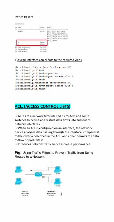
Switch1:client
4)Assign interfaces on clients to the required vlans.
ACL: (ACCESS CONTROL LISTS)
ACLs are a network filter utilized by routers and some switches to permit and restrict data flows into and out of network interfaces. When an ACL is configured on an interface, the network device analyzes data passing through the interface, compares it to the criteria described in the ACL, and either permits the data to flow or prohibits it. It reduces network traffic hence increase performance.
Fig: Using Traffic Filters to Prevent Traffic from Being
Routed to a Network

Directions in which ACL filter Traffic: INBOUND ACL: Incoming packets are processed before they are routed to an outbound interface. An inbound ACL is efficient because it saves the overhead of routing lookups if the packet will be discarded after it is denied by the filtering tests. If the packet is permitted by the tests, it is processed for router. OUTBOUND ACL: Incoming packets are routed to the outbound interface and then processed through the outbound ACL and packet is dropped at the outbound interface if they match the access list. ACL TYPES: a) NAMED AND NUMBERED ACL: ACL statements can be grouped in two ways: by number or by name. Numbered acl:
Router(config)#access-list ACL_# deny | permit condition Here ACL_# could be 1 – 99 for a standard ACL ; 100 – 199 for an extended ACL. Named acl: It allows an administrator to give a descriptive name to the ACL. Specific entry could be deleted in the named ACL. Router(config)# ip access-list standard/extended name_of_ACL b) STANDARD/EXTENDED ACL: Standard acl: check only the source address of the packet and permits or denies entire TCP/IP suite. cisco recommends that they are placed as close to the destination as possible. Named_syntax: Creating ACL: Router(config)# ip access-list standard name_of_ACL Router(config-std-nacl)# deny {source [src_wildcard] | any} Router(config-std-nacl)# permit {source [src_wildcard] | any} Router(config-std-nacl)# exit\
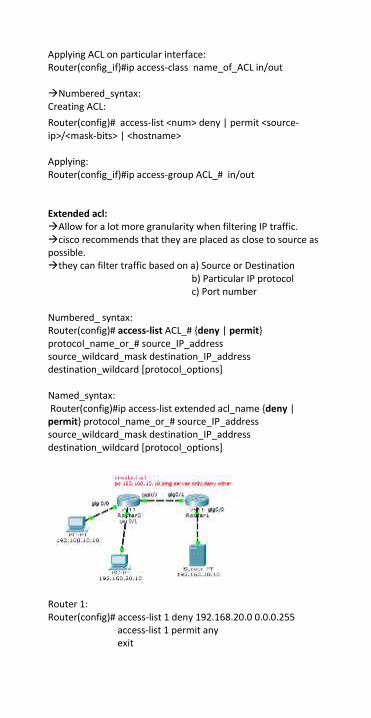
Applying ACL on particular interface: Router(config_if)#ip access-class name_of_ACL in/out Numbered_syntax: Creating ACL:
Router(config)# access-list <num> deny | permit <source-ip>/<mask-bits> | <hostname> Applying: Router(config_if)#ip access-group ACL_# in/out Extended acl: Allow for a lot more granularity when filtering IP traffic. cisco recommends that they are placed as close to source as possible. they can filter traffic based on a) Source or Destination b) Particular IP protocol c) Port number Numbered_ syntax: Router(config)# access-list ACL_# {deny | permit} protocol_name_or_# source_IP_address source_wildcard_mask destination_IP_address destination_wildcard [protocol_options] Named_syntax: Router(config)#ip access-list extended acl_name {deny | permit} protocol_name_or_# source_IP_address source_wildcard_mask destination_IP_address destination_wildcard [protocol_options]
Router 1: Router(config)# access-list 1 deny 192.168.20.0 0.0.0.255 access-list 1 permit any exit

router(config)#interface GigabitEthernet0/0 router(config_if)# IP address 192.168.30.1 255.255.255.0 router(config_if)# IP access-group 1 out router(config-if)# exit.
NAT (network address translation):
When communicating to device in a public network, your device needs to use a source address that is your public address. Static NAT is used to do a one-to –one mapping between an inside address and an outside address. We use NAT where: Your ISP did not provide you sufficient public IP addresses. Your company are going to merge with a company which use same address space. Where you want to hide your internal IP address space from outside? You want to assign the same IP address to multiple machines.

Four type of addresses are used in NATing: 1)Inside local address: The IPv4 address that is assigned to a host on the inside network. 2)Inside global address: a legitimate IPv4 address assigned by the ISP that represents one or more inside local addresses to the outside world. 3)Outside global address: an outside device with a registered public IP address. 4)Outside local address: an outside device with an assigned private IP address. There are 3 types of NAT: Static NAT Dynamic NAT PAT STATIC NAT: In this, manual translation is performed by an address translation device. It provides a permanent mapping between internal and the public IP address. If you have 100 devices, you need to create 100 static entries in the address translation table. Static translation is done for inside resources that outside people want to access. DYNAMIC NAT: It is used when you have a “pool” of public addresses that you want to assign to your internal host dynamically. It is not used for servers or other devices that need to be accessible from the internet.

Dynamic NAT is mostly used when inside users want to access outside resources. We have to make a pool of public IP addresses. We have to define an ACL to permit only those addresses that are allowed to be translated. ACL list : carries private address. Access-list acl_# permit x.y.z.w wx.wy.wz.ww. ; x.y.z.w is private network NAT pool: carries global address IP NAT pool pool_name <address_range_available> netmask <subnetmask> IP NAT inside Source list acl_# pool pool_name NAT OVERLOAD: Sometimes it is also called PAT. We can configure NAT overload in two ways, depending upon how many public IP addresses you have available. a) We have only one public IP address allocated to our ISP. Here we have to specify the outside interface instead of NAT pool. b) When our ISP gave more than one public IP address, but not enough for a dynamic or static mapping. We will add OVERLOAD word for a router to know to use traffic Flow identification using port numbers, instead of mapping a private to public IP address dynamically.
Scenario implementing NAT and PAT
1)Configration on router implementing PAT

Default routing
2)Configuration on other router implementing NAT
Default routing

PROJECT: CISCO HIERARCHICAL MODEL
INTRODUCTION: It is a model used as the foundation to deploy
a reliable network in the organisation. This model was
introduced by cisco in 1999.
Constructing a network is similar to construction of house. If
the engineering details are skipped at foundation level then
eventually it will fall. Similarly to have advanced services on
network like IP video , IP telephony etc; the foundation need to
be rock solid. This is what is achieved by the cisco hierarchical
model.
DESIGN AND IMPLEMENTATION
Design principles applied to develop network:
RELIABILITY: the network must be consistent in its operation.
MODULARITY: enables growing of network on demand basis
that is it must scalable. New modules can easily be added
without the need of redesigning the existing one.
RESILIENCY: Meets user expectation of network always being
available.
FLEXIBILITY: allows intelligent traffic load sharing by using all
network resources.
MANAGEABILITY: allows easier isolation of problems.

This model uses layered approach which makes it
Easy to understand.
Functionality of specific device optimised for its position in
network and the specific role it plays.
It avoids need of fully meshed network in which all network
nodes are interconnected.
Clarifies role of each device in each layer.
It reduces fault domain
Easy management
Reduces workload on network and avoids device to
communicate with too many devices.
The three layers of the cisco layered approach are :
a) ACCESS LAYER
b) DISTRIBUTION LAYER
c) CORE LAYER
ACCESS LAYER:
Closest to the users.
It provides network access to end users via IP phones, EDGE
devices, workstations etc.
Works on OSI second layer (data link layer) devices.
Switches and the end devices are used in this layer.
DISTRIBUTION LAYER
It is the layer that operates between access layer and the
core layer.
Uses layer 2 and layer 3 devices.
Security policies and provision are applied onto this layer
only. It is implemented using ACLS and FIREWALLS.

Routing is done onto this layer to facilitate client-server
interconnection.
Routers used in this layer are used as demarcation point for
the broadcast domains of access layer.
Redundant Distribution layer devices provide high availability
to the end user and equal cost paths to the core.
CORE LAYER:
It is considered as the backbone of the network
It switches packet as fast as possible, high speed switching.
IT should not perform packet manipulation (no ACLS, no
routing , no VLAN trunking etc )
Core is responsible for just forwarding the traffic, no routing
because performance is compromised as every time packet
passes through router it is being regeneration. There by, layer 3
switches are used.
Traffic moving across core must be the traffic between
different distribution layer devices.
Fault tolerance is being provided with the introduction of
backup links.
WHY CISCO HIERARCHICAL MODEL OVER FULLY MESHED??
Though fully meshed network also provide redundancy as
each node is connected to every other node in the network
established. If one link fails, alternative path is provided.
However, unlike hierarchical model, fully meshed doesn’t have
consistent convergence if link fails. Also cost per port is high for
fully meshed .
Layer 3 switches used in the model provides faster
convergence if link fails.
cost per port is considerably reduced in the partial meshed
network of cisco hierarchical model.
Scalability is improved as in partially meshed the relations
with neighbours reduced and meshing also.